WO2021010107A1 - Dispositif de réfrigération, tuyau de montage de capteur de température et structure de montage de capteur de température - Google Patents
Dispositif de réfrigération, tuyau de montage de capteur de température et structure de montage de capteur de température Download PDFInfo
- Publication number
- WO2021010107A1 WO2021010107A1 PCT/JP2020/024671 JP2020024671W WO2021010107A1 WO 2021010107 A1 WO2021010107 A1 WO 2021010107A1 JP 2020024671 W JP2020024671 W JP 2020024671W WO 2021010107 A1 WO2021010107 A1 WO 2021010107A1
- Authority
- WO
- WIPO (PCT)
- Prior art keywords
- temperature sensor
- sensor mounting
- temperature side
- surface area
- large surface
- Prior art date
Links
Images


Classifications
-
- F—MECHANICAL ENGINEERING; LIGHTING; HEATING; WEAPONS; BLASTING
- F25—REFRIGERATION OR COOLING; COMBINED HEATING AND REFRIGERATION SYSTEMS; HEAT PUMP SYSTEMS; MANUFACTURE OR STORAGE OF ICE; LIQUEFACTION SOLIDIFICATION OF GASES
- F25B—REFRIGERATION MACHINES, PLANTS OR SYSTEMS; COMBINED HEATING AND REFRIGERATION SYSTEMS; HEAT PUMP SYSTEMS
- F25B49/00—Arrangement or mounting of control or safety devices
- F25B49/02—Arrangement or mounting of control or safety devices for compression type machines, plants or systems
- F25B49/022—Compressor control arrangements
-
- F—MECHANICAL ENGINEERING; LIGHTING; HEATING; WEAPONS; BLASTING
- F25—REFRIGERATION OR COOLING; COMBINED HEATING AND REFRIGERATION SYSTEMS; HEAT PUMP SYSTEMS; MANUFACTURE OR STORAGE OF ICE; LIQUEFACTION SOLIDIFICATION OF GASES
- F25B—REFRIGERATION MACHINES, PLANTS OR SYSTEMS; COMBINED HEATING AND REFRIGERATION SYSTEMS; HEAT PUMP SYSTEMS
- F25B41/00—Fluid-circulation arrangements
- F25B41/40—Fluid line arrangements
-
- F—MECHANICAL ENGINEERING; LIGHTING; HEATING; WEAPONS; BLASTING
- F25—REFRIGERATION OR COOLING; COMBINED HEATING AND REFRIGERATION SYSTEMS; HEAT PUMP SYSTEMS; MANUFACTURE OR STORAGE OF ICE; LIQUEFACTION SOLIDIFICATION OF GASES
- F25B—REFRIGERATION MACHINES, PLANTS OR SYSTEMS; COMBINED HEATING AND REFRIGERATION SYSTEMS; HEAT PUMP SYSTEMS
- F25B39/00—Evaporators; Condensers
-
- F—MECHANICAL ENGINEERING; LIGHTING; HEATING; WEAPONS; BLASTING
- F25—REFRIGERATION OR COOLING; COMBINED HEATING AND REFRIGERATION SYSTEMS; HEAT PUMP SYSTEMS; MANUFACTURE OR STORAGE OF ICE; LIQUEFACTION SOLIDIFICATION OF GASES
- F25B—REFRIGERATION MACHINES, PLANTS OR SYSTEMS; COMBINED HEATING AND REFRIGERATION SYSTEMS; HEAT PUMP SYSTEMS
- F25B49/00—Arrangement or mounting of control or safety devices
-
- F—MECHANICAL ENGINEERING; LIGHTING; HEATING; WEAPONS; BLASTING
- F25—REFRIGERATION OR COOLING; COMBINED HEATING AND REFRIGERATION SYSTEMS; HEAT PUMP SYSTEMS; MANUFACTURE OR STORAGE OF ICE; LIQUEFACTION SOLIDIFICATION OF GASES
- F25B—REFRIGERATION MACHINES, PLANTS OR SYSTEMS; COMBINED HEATING AND REFRIGERATION SYSTEMS; HEAT PUMP SYSTEMS
- F25B6/00—Compression machines, plants or systems, with several condenser circuits
- F25B6/04—Compression machines, plants or systems, with several condenser circuits arranged in series
-
- F—MECHANICAL ENGINEERING; LIGHTING; HEATING; WEAPONS; BLASTING
- F25—REFRIGERATION OR COOLING; COMBINED HEATING AND REFRIGERATION SYSTEMS; HEAT PUMP SYSTEMS; MANUFACTURE OR STORAGE OF ICE; LIQUEFACTION SOLIDIFICATION OF GASES
- F25B—REFRIGERATION MACHINES, PLANTS OR SYSTEMS; COMBINED HEATING AND REFRIGERATION SYSTEMS; HEAT PUMP SYSTEMS
- F25B7/00—Compression machines, plants or systems, with cascade operation, i.e. with two or more circuits, the heat from the condenser of one circuit being absorbed by the evaporator of the next circuit
-
- F—MECHANICAL ENGINEERING; LIGHTING; HEATING; WEAPONS; BLASTING
- F25—REFRIGERATION OR COOLING; COMBINED HEATING AND REFRIGERATION SYSTEMS; HEAT PUMP SYSTEMS; MANUFACTURE OR STORAGE OF ICE; LIQUEFACTION SOLIDIFICATION OF GASES
- F25D—REFRIGERATORS; COLD ROOMS; ICE-BOXES; COOLING OR FREEZING APPARATUS NOT OTHERWISE PROVIDED FOR
- F25D11/00—Self-contained movable devices, e.g. domestic refrigerators
-
- F—MECHANICAL ENGINEERING; LIGHTING; HEATING; WEAPONS; BLASTING
- F25—REFRIGERATION OR COOLING; COMBINED HEATING AND REFRIGERATION SYSTEMS; HEAT PUMP SYSTEMS; MANUFACTURE OR STORAGE OF ICE; LIQUEFACTION SOLIDIFICATION OF GASES
- F25D—REFRIGERATORS; COLD ROOMS; ICE-BOXES; COOLING OR FREEZING APPARATUS NOT OTHERWISE PROVIDED FOR
- F25D29/00—Arrangement or mounting of control or safety devices
-
- G—PHYSICS
- G01—MEASURING; TESTING
- G01K—MEASURING TEMPERATURE; MEASURING QUANTITY OF HEAT; THERMALLY-SENSITIVE ELEMENTS NOT OTHERWISE PROVIDED FOR
- G01K1/00—Details of thermometers not specially adapted for particular types of thermometer
- G01K1/08—Protective devices, e.g. casings
-
- G—PHYSICS
- G01—MEASURING; TESTING
- G01K—MEASURING TEMPERATURE; MEASURING QUANTITY OF HEAT; THERMALLY-SENSITIVE ELEMENTS NOT OTHERWISE PROVIDED FOR
- G01K1/00—Details of thermometers not specially adapted for particular types of thermometer
- G01K1/14—Supports; Fastening devices; Arrangements for mounting thermometers in particular locations
- G01K1/143—Supports; Fastening devices; Arrangements for mounting thermometers in particular locations for measuring surface temperatures
-
- G—PHYSICS
- G01—MEASURING; TESTING
- G01K—MEASURING TEMPERATURE; MEASURING QUANTITY OF HEAT; THERMALLY-SENSITIVE ELEMENTS NOT OTHERWISE PROVIDED FOR
- G01K13/00—Thermometers specially adapted for specific purposes
- G01K13/02—Thermometers specially adapted for specific purposes for measuring temperature of moving fluids or granular materials capable of flow
- G01K13/026—Thermometers specially adapted for specific purposes for measuring temperature of moving fluids or granular materials capable of flow of moving liquids
-
- F—MECHANICAL ENGINEERING; LIGHTING; HEATING; WEAPONS; BLASTING
- F25—REFRIGERATION OR COOLING; COMBINED HEATING AND REFRIGERATION SYSTEMS; HEAT PUMP SYSTEMS; MANUFACTURE OR STORAGE OF ICE; LIQUEFACTION SOLIDIFICATION OF GASES
- F25B—REFRIGERATION MACHINES, PLANTS OR SYSTEMS; COMBINED HEATING AND REFRIGERATION SYSTEMS; HEAT PUMP SYSTEMS
- F25B2313/00—Compression machines, plants or systems with reversible cycle not otherwise provided for
- F25B2313/031—Sensor arrangements
-
- F—MECHANICAL ENGINEERING; LIGHTING; HEATING; WEAPONS; BLASTING
- F25—REFRIGERATION OR COOLING; COMBINED HEATING AND REFRIGERATION SYSTEMS; HEAT PUMP SYSTEMS; MANUFACTURE OR STORAGE OF ICE; LIQUEFACTION SOLIDIFICATION OF GASES
- F25B—REFRIGERATION MACHINES, PLANTS OR SYSTEMS; COMBINED HEATING AND REFRIGERATION SYSTEMS; HEAT PUMP SYSTEMS
- F25B2400/00—General features or devices for refrigeration machines, plants or systems, combined heating and refrigeration systems or heat-pump systems, i.e. not limited to a particular subgroup of F25B
- F25B2400/16—Receivers
-
- F—MECHANICAL ENGINEERING; LIGHTING; HEATING; WEAPONS; BLASTING
- F25—REFRIGERATION OR COOLING; COMBINED HEATING AND REFRIGERATION SYSTEMS; HEAT PUMP SYSTEMS; MANUFACTURE OR STORAGE OF ICE; LIQUEFACTION SOLIDIFICATION OF GASES
- F25B—REFRIGERATION MACHINES, PLANTS OR SYSTEMS; COMBINED HEATING AND REFRIGERATION SYSTEMS; HEAT PUMP SYSTEMS
- F25B2600/00—Control issues
- F25B2600/02—Compressor control
- F25B2600/021—Inverters therefor
-
- F—MECHANICAL ENGINEERING; LIGHTING; HEATING; WEAPONS; BLASTING
- F25—REFRIGERATION OR COOLING; COMBINED HEATING AND REFRIGERATION SYSTEMS; HEAT PUMP SYSTEMS; MANUFACTURE OR STORAGE OF ICE; LIQUEFACTION SOLIDIFICATION OF GASES
- F25B—REFRIGERATION MACHINES, PLANTS OR SYSTEMS; COMBINED HEATING AND REFRIGERATION SYSTEMS; HEAT PUMP SYSTEMS
- F25B2700/00—Sensing or detecting of parameters; Sensors therefor
- F25B2700/21—Temperatures
- F25B2700/2103—Temperatures near a heat exchanger
-
- F—MECHANICAL ENGINEERING; LIGHTING; HEATING; WEAPONS; BLASTING
- F25—REFRIGERATION OR COOLING; COMBINED HEATING AND REFRIGERATION SYSTEMS; HEAT PUMP SYSTEMS; MANUFACTURE OR STORAGE OF ICE; LIQUEFACTION SOLIDIFICATION OF GASES
- F25B—REFRIGERATION MACHINES, PLANTS OR SYSTEMS; COMBINED HEATING AND REFRIGERATION SYSTEMS; HEAT PUMP SYSTEMS
- F25B2700/00—Sensing or detecting of parameters; Sensors therefor
- F25B2700/21—Temperatures
- F25B2700/2116—Temperatures of a condenser
- F25B2700/21163—Temperatures of a condenser of the refrigerant at the outlet of the condenser
-
- Y—GENERAL TAGGING OF NEW TECHNOLOGICAL DEVELOPMENTS; GENERAL TAGGING OF CROSS-SECTIONAL TECHNOLOGIES SPANNING OVER SEVERAL SECTIONS OF THE IPC; TECHNICAL SUBJECTS COVERED BY FORMER USPC CROSS-REFERENCE ART COLLECTIONS [XRACs] AND DIGESTS
- Y02—TECHNOLOGIES OR APPLICATIONS FOR MITIGATION OR ADAPTATION AGAINST CLIMATE CHANGE
- Y02B—CLIMATE CHANGE MITIGATION TECHNOLOGIES RELATED TO BUILDINGS, e.g. HOUSING, HOUSE APPLIANCES OR RELATED END-USER APPLICATIONS
- Y02B30/00—Energy efficient heating, ventilation or air conditioning [HVAC]
- Y02B30/70—Efficient control or regulation technologies, e.g. for control of refrigerant flow, motor or heating
Definitions
- the present disclosure relates to a refrigerating apparatus, particularly a refrigerating apparatus including a dual refrigerant circuit, and a temperature sensor mounting tube and a temperature sensor mounting structure.
- Patent Document 1 conventionally, a high temperature side refrigerant circuit and a low temperature side refrigerant circuit are provided, and a dual refrigerant circuit for cooling the refrigerant in the low temperature side refrigerant circuit by the refrigerant in the high temperature side refrigerant circuit is provided. Refrigerating equipment is used.
- the controlled device such as a compressor is controlled so that the temperature of the storage where the object to be cooled is placed becomes the target temperature.
- the present disclosure aims to operate the refrigeration system more efficiently.
- the refrigerating apparatus includes a high temperature side refrigerant circuit in which the high temperature side refrigerant circulates, a low temperature side refrigerant circuit in which the low temperature side refrigerant circulates, and a cascade heat exchanger that cools the low temperature side refrigerant with the high temperature side refrigerant.
- a low temperature side decompressor is arranged on the downstream side of the cascade heat exchanger, and a piping portion between the cascade heat exchanger and the low temperature side decompressor is provided.
- a temperature sensor is installed.
- the refrigerating apparatus can be operated more efficiently.
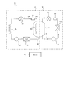
- FIG. 1 shows an example of a refrigerant circuit included in the refrigerating apparatus according to the first embodiment of the present disclosure.
- the refrigerant circuit 1 is provided in, for example, a refrigerating device such as an ultra-low temperature freezer in which the internal temperature of the storage is ⁇ 80 ° C. or lower.
- the refrigerant circuit 1 is a dual refrigerant circuit having a high temperature side refrigerant circuit 10 and a low temperature side refrigerant circuit 20 in which refrigerants circulate independently of each other.
- the high temperature side refrigerant circuit 10 includes a high temperature side compressor 11, a high temperature side condenser 12, a high temperature side decompressor 13, a high temperature side evaporator 14, a dryer 15, and a liquid receiver 16.
- the high temperature side evaporator 14 is an outer tube of the cascade heat exchanger 30 described later, and surrounds the second heat exchanger 23 described later.
- Each of the above devices is connected by a predetermined pipe (high temperature side pipe) so that the refrigerant discharged from the high temperature side compressor 11 (high temperature side refrigerant) returns to the high temperature side compressor 11 again.
- the high temperature side refrigerant circulates in the direction of the arrow in FIG. That is, in the high temperature side refrigerant circuit 10, the high temperature side refrigerant flows through the high temperature side compressor 11, the high temperature side condenser 12, the dryer 15, the high temperature side decompressor 13, the high temperature side evaporator 14, and the liquid receiver 16 in this order. , Return to the high temperature side compressor 11.
- the temperature can be lowered to about ⁇ 40 ° C. in the high temperature side evaporator 14.
- the low temperature side refrigerant circuit 20 includes a low temperature side compressor 21, a first heat exchanger 22, a second heat exchanger 23, a low temperature side decompressor 24, a low temperature side evaporator 25, and a large surface area portion 26. Be prepared.
- each of the above devices is connected by a predetermined pipe (low temperature side pipe) so that the refrigerant discharged from the low temperature side compressor 21 (low temperature side refrigerant) returns to the low temperature side compressor 21 again.
- the low temperature side refrigerant circulates in the direction of the arrow in FIG. That is, in the low temperature side refrigerant circuit 20, the low temperature side refrigerant is the low temperature side compressor 21, the first heat exchanger 22, the second heat exchanger 23, the large surface area portion 26, the low temperature side decompressor 24, and the low temperature side evaporator 25. In this order, and returns to the low temperature side compressor 21.
- an ultralow temperature of ⁇ 80 ° C. or lower can be obtained in the low temperature side evaporator 25.
- the first heat exchanger 22 cools the refrigerant passing through the inside in the gas phase.
- the first heat exchanger 22 may be a condenser that condenses the refrigerant passing through the inside thereof.
- the second heat exchanger 23 is the inner tube of the cascade heat exchanger 30. That is, the second heat exchanger 23, which is an inner pipe, is surrounded by the high temperature side evaporator 14 which is an outer pipe. In the cascade heat exchanger 30, the low-temperature refrigerant passing through the high-temperature side evaporator 14 and the high-temperature refrigerant passing through the second heat exchanger 23 exchange heat. At this time, the high-temperature refrigerant passing through the second heat exchanger 23 condenses. When the first heat exchanger 22 is a condenser, the second heat exchanger 23 cools the liquid phase refrigerant passing through the inside thereof.
- the unit 26 is arranged.
- the large surface area portion 26 is a portion having a larger surface area per unit length in the direction in which the refrigerant flows than any of the low temperature side pipes, particularly the upstream side pipes 26a and the downstream side pipes 26b.
- the large surface area portion 26 is, for example, a large-diameter pipe or a container-shaped member.
- the large-diameter pipe is a pipe having a larger volume per unit length in the direction in which the refrigerant flows than at least the upstream side pipe 26a and the downstream side pipe 26b.
- the container-shaped member is, for example, a dehydrator that adsorbs water in the low-temperature side refrigerant circuit 20.
- the large surface area portion 26 may have an inner diameter of the same size as the inner diameters of the upstream side pipe 26a and the downstream side pipe 26b, and may be thicker than the upstream side pipe 26a and the downstream side pipe 26b. In the following description, the large surface area portion 26 will be described as a container-shaped member.
- the upstream side pipe 26a is connected to the large surface area portion 26 from the upstream side.
- the upstream side pipe 26a may connect the second heat exchanger 23 and the large surface area portion 26.
- a downstream pipe 26b is connected to the large surface area portion 26 from the downstream side.
- the downstream side pipe 26b may connect the large surface area portion 26 and the low temperature side decompressor 24.
- the refrigerant flowing into the large surface area portion 26 is a liquid.
- the liquid refrigerant (low temperature side refrigerant) that flows into the large surface area portion 26 from the upstream side of the large surface area portion 26 and flows out to the downstream side of the large surface area portion 26 is temporarily stored. In other words, it flows inside the large surface area portion 26 at a relatively low speed.
- a temperature sensor T1 for detecting the temperature of the refrigerant passing through the large surface area portion 26 is installed on the surface of the large surface area portion 26.
- the high temperature side refrigerant circuit 10 and the low temperature side refrigerant circuit 20 may each have auxiliary equipment (not shown).
- auxiliary equipment not shown.
- a temperature sensor T1 is installed on the surface of those auxiliary machines. May be good.
- the detected value of the temperature sensor T1 is input to the control unit 40 provided in the refrigerating device.
- the control unit 40 adjusts the high temperature side compressor 11 or the inverter that adjusts the rotation speed thereof, and the low temperature side compressor 21 or its rotation speed based on the set temperature of the storage and the detection value of the temperature sensor T1. Control at least one of the inverters.
- the refrigerating device also includes a temperature sensor other than the temperature sensor T1, for example, a temperature sensor that detects the temperature inside the storage, and the control unit 40 is based on the detection values of a plurality of temperature sensors including the temperature sensor T1.
- the controlled device may be controlled.
- the object to be cooled arranged in the storage is the refrigerant flowing in the low temperature side evaporator 25, that is, the refrigerant circulating in the low temperature side refrigerant circuit 20 (low temperature side refrigerant). ) Is cooled. Further, the temperature sensor T1 is installed on the low temperature side refrigerant circuit 20 side.
- the temperature sensor T1 can detect the temperature of the low temperature side refrigerant that directly acts on the cooling of the cooling object, not the temperature of the high temperature side refrigerant that indirectly acts on the cooling of the cooling object. Therefore, more efficient operation of the refrigerant circuit 1 can be realized by controlling the controlled device such as the high temperature side compressor 11 or the low temperature side compressor 21 by using the detected value of the temperature sensor T1.
- the temperature sensor T1 is not in the gas phase or the gas-liquid mixed state, but is at the position where the refrigerant which is the liquid phase flows, specifically, the downstream side of the second heat exchanger 23 and the upstream side of the low temperature side decompressor 24. It is installed in the piping section located on the side. Liquids have higher thermal conductivity than gases. Therefore, when the temperature of the flowing refrigerant changes, the temperature change of the refrigerant can be detected more quickly in the portion where the liquid phase refrigerant flows than in the portion where the gas phase refrigerant flows. That is, according to the present embodiment, the temperature change of the refrigerant flowing through the low temperature side refrigerant circuit can be detected more quickly, and by extension, more efficient operation of the refrigerant circuit 1 can be realized.
- the low temperature side evaporator 25 is a portion in the refrigerant circuit 1 in which the refrigerant in the lowest temperature state flows, is arranged so as to surround the storage in which the object to be cooled is arranged, and is contained in the heat insulating material. It is in an enclosed state. Therefore, if the temperature sensor T1 is installed in the low temperature side evaporator 25 or the piping near the upstream side or the downstream side thereof, the temperature sensor T1 is also enclosed in the heat insulating material, and it is necessary to remove the heat insulating material when performing maintenance. Occurs. That is, it becomes difficult to maintain the temperature sensor T1.
- the temperature sensor T1 is arranged between the second heat exchanger 23 and the low temperature side decompressor 24, that is, a portion that does not necessarily have to be sealed in the heat insulating material. Therefore, according to this embodiment, maintenance of the temperature sensor T1 or its mounting structure can be easily performed.
- the temperature of the refrigerant flowing in the large surface area portion 26 is also sufficiently lower than the outside air. Therefore, there is a possibility that condensed water or ice adheres to the large surface area portion 26, that is, around the temperature sensor T1. If dew condensation water adheres around the temperature sensor T1, the detection temperature may become inaccurate. Further, if ice adheres, the temperature sensor T1 may be damaged.
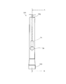
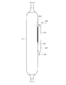
- FIG. 2 is a front view of the temperature sensor mounting pipe 101 according to the first embodiment.
- FIG. 3 is a cross-sectional view taken along the line AA of FIG. 2, that is, a vertical cross-sectional view of the temperature sensor mounting tube 101.
- the temperature sensor mounting pipe 101 is formed by processing a metal pipe, for example, a copper pipe. One end of the temperature sensor mounting pipe 101 is open, forming an open end 102. 2 and 3 show a temperature sensor mounting tube 101 in a state where the opening end 102 is arranged so as to be located on the upper side.
- the description will be made on the assumption that the opening end 102 is located on the upper side, but it goes without saying that the opening end 102 does not have to be located on the upper side.
- the other end of the temperature sensor mounting tube 101 is sealed, forming a sealed end 103.
- the sealing end 103 is formed by crimping the other end of the temperature sensor mounting pipe 101 so that two flat plates are overlapped with each other, and then welding the opposing flat plate-shaped portions to each other. It is formed by sealing the gap between the two with the welded portion 103a.
- the weld 103a extends from the left end to the right end of the flat plate portion for complete sealing.
- the narrowed portion 104 is formed by crimping a portion between the open end portion 102 and the sealing end portion 103. In the example shown in FIG. 2, a gap is left inside the narrowed portion 104, but the narrowed portion 104 may be formed by being crimped so as not to leave a gap.
- a first intermediate portion 105 is formed between the opening end portion 102 and the narrowed portion 104.
- the first intermediate portion 105 is a hollow pipe-shaped portion having one end narrowed.
- a second intermediate portion 106 is formed between the sealing end portion 103 and the narrowed portion 104.
- the second intermediate portion 106 is a hollow pipe-shaped portion having both ends narrowed.
- the distance between the sealing end portion 103 and the narrowed portion 104, that is, the length of the second intermediate portion 106 is larger than the length of the welded portion 103a.
- FIG. 3 shows the temperature sensor T1 inserted into the temperature sensor mounting tube 101 from the opening end.
- the temperature sensor T1 is placed on the narrowed portion 104.
- the temperature sensor T1 may be sandwiched by the narrowed portion 104. According to the temperature sensor mounting tube 101, the temperature sensor T1 can be positioned at a predetermined position regardless of whether it is placed on the narrowed portion 104 or sandwiched by the narrowed portion 104.
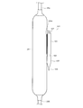
- FIG. 4 is a diagram showing a temperature sensor mounting structure according to the first embodiment of the present disclosure.
- the temperature sensor mounting tube 101 is attached to the large surface area portion 26 made of metal by welding.
- the first intermediate portion 105 is welded to the large surface area portion 26 so that the welded portion 105a is formed.
- the temperature sensor mounting tube 101 is mounted so that the temperature sensor T1 arranged inside the temperature sensor mounting tube 101, that is, the narrowed portion 104 is located at the center of the large surface area portion 26 in the front view. By mounting at such a position, the surface temperature of the large surface area portion 26 can be uniformly sensed, and the temperature of the liquid inside the large surface area portion 26 can be measured more accurately.
- the first intermediate portion 105 is longer than the other portions constituting the temperature sensor mounting pipe 101. Therefore, a sufficient length of the welded portion 105a can be secured, and the temperature sensor mounting pipe 101 can be reliably attached to the large surface area portion 26.
- the length and position of the welded portion 105a are not particularly limited as long as the temperature sensor mounting pipe 101 is securely attached to the large surface area portion 26.
- the temperature sensor mounting pipe 101 When the temperature sensor mounting pipe 101 is attached to the large surface area portion 26 by welding, heat is generated and transmitted to the temperature sensor mounting pipe 101. However, a sufficient distance is secured between the sealing end portion 103 and the narrowed portion 104. Specifically, as described above, the distance between the sealing end portion 103 and the narrowed portion 104 is larger than the length of the welded portion 103a. Therefore, of the heat generated when the temperature sensor mounting tube 101 is attached to the large surface area portion 26 by welding, the amount of heat transferred to the sealing end portion 103 is sufficiently small, and the temperature rise at the sealing end portion 103 is small. Therefore, when the temperature sensor mounting tube 101 is attached to the large surface area portion 26 by welding, it is possible to prevent the welded portion 103a at the sealing end portion 103 from melting and insufficient sealing of the sealing end portion 103. Can be done.
- the temperature sensor T1 After being attached by welding, the temperature sensor T1 is inserted into the temperature sensor attachment tube 101 via the open end 102. As described above, since the temperature sensor T1 is placed on the narrowed portion 104, the temperature sensor T1 can be positioned at a predetermined position.
- the temperature sensor T1 may be sandwiched by the narrowed portion 104.
- the temperature sensor T1 is sandwiched by the narrowed portion 104, even if the large surface area portion 26 vibrates under the influence of, for example, the high temperature side compressor 11 or the low temperature side compressor 21, the temperature sensor mounting tube 101
- the temperature sensor T1 does not run wild inside, and can always maintain a state of being in contact with the large surface area portion 26 via the temperature sensor mounting tube 101. That is, the temperature of the refrigerant can be measured more accurately.
- the temperature sensor T1 can be positioned at a predetermined position as in the case where the temperature sensor T1 is placed on the narrowed portion 104.
- the opening of the opening end 102 is sealed with, for example, a paste-like sealing material (not shown).
- a paste-like sealing material not shown.
- the temperature sensor mounting tube 101 is completely shut off from the outside air. Therefore, for example, even when the large surface area portion 26 becomes low temperature or extremely low temperature, water droplets generated by dew condensation of moisture in the surrounding atmosphere adhere to the temperature sensor T1, and the temperature measurement becomes inaccurate. , It is possible to prevent ice from adhering and damaging the temperature sensor T1.
- the sealing end portion 103 may be sealed by the welded portion 103a before the temperature sensor mounting pipe 101 is attached to the large surface area portion 26, or is attached to the large surface area portion 26 via the welded portion 105a. Later, it may be sealed by the weld 103a. In either case, the sealing end 103 can be sealed by simply welding, so that the lower end of the temperature sensor mounting tube 101 is compared with the case of sealing using, for example, a paste-like sealing material. The part can be easily sealed. When the sealing end 103 is sealed after the temperature sensor mounting tube 101 is attached to the large surface area 26, the working posture tends to be unstable when the sealing end 103 is sealed using a paste-like sealing material. Therefore, the advantage is particularly large.
- the temperature sensor mounting tube is attached to the large surface area portion 26.
- the sealing end portion 103 can be easily sealed. That is, if it is sealed without using a sealing material, it does not necessarily have to be sealed by the welded portion 103a.
- the sealing end portion 103 may be sealed by mechanical coupling such as caulking or pressure contacting the opposing flat plate-shaped portions of the sealing end portion 103 with each other.
- the sealing end 103 may be sealed by material bonding such as brazing welding, ultrasonic welding, and welding.
- the sealing end 103 may be sealed by a chemical bond such as adhesion.
- the sealing end 103 By sealing the sealing end 103 by combining any two or more of mechanical bonding, material bonding, and chemical bonding, the sealing becomes more reliable, and the temperature sensor T1 in the temperature sensor mounting tube 101 can be sealed. It can be more reliably blocked from the outside air.
- Patent Document 2 Japanese Unexamined Patent Publication No. 08-0823308
- the fixing device disclosed in Patent Document 2 requires a caulking operation after inserting the temperature sensor into the fixing device. Therefore, there is a problem that the installation work is troublesome. Further, in the fixing device disclosed in Patent Document 2, the temperature sensor is exposed to the outside air. Therefore, when the temperature is measured by the temperature sensor at a low temperature, moisture in the outside air may condense and the temperature measurement may become inaccurate. Further, when the part where the temperature is measured by the temperature sensor is extremely low temperature, the moisture in the outside air may solidify and damage the temperature sensor.
- An object of the present invention is to provide a sensor mounting structure.
- the temperature sensor mounting tube according to the present disclosure is made of metal and is arranged between an opening end portion having an opening into which the temperature sensor is inserted, a sealing end portion, and the opening end portion and the sealing end portion. It is provided with a narrowed portion.
- the temperature sensor mounting structure includes the temperature sensor mounting pipe and a metal attachment to which the temperature sensor mounting pipe is mounted, and is located between the open end portion and the narrowed portion. The portion is attached to the object to be attached by welding.
- the temperature sensor can be easily mounted and the temperature can be measured accurately without damaging the temperature sensor.
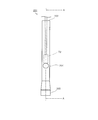
- FIG. 5 is a front view of the temperature sensor mounting tube 201 according to the second embodiment of the present disclosure
- FIG. 6 is a cross-sectional view taken along the line AA of FIG. 5, that is, the temperature sensor mounting tube 201 according to the present disclosure. It is a vertical sectional view of.
- the temperature sensor mounting pipe 201 is formed by processing a pipe made of metal, for example, copper.
- One end of the temperature sensor mounting pipe 201 is open, and constitutes the open end portion 202.
- 5 and 6 show a temperature sensor mounting tube 201 in a state where the opening end 202 is arranged so as to be located on the upper side.
- the description will be made on the assumption that the opening end portion 202 is located on the upper side, but it goes without saying that the opening end portion 202 does not have to be located on the upper side.
- the other end of the temperature sensor mounting tube 201 is sealed and constitutes the sealed end portion 203.
- the sealing end portion 203 is formed by crimping the other end of the temperature sensor mounting pipe 201 so that two flat plates are overlapped with each other, and then welding the opposing flat plate-shaped portions to each other. It is formed by sealing the gap between the two with the welded portion 203a.
- the welded portion 203a extends from the left end to the right end of the flat plate portion for complete sealing.
- the narrowed portion 204 is formed by crimping a portion between the open end portion 202 and the sealing end portion 203. In the example shown in FIG. 5, a gap is left inside the narrowed portion 204, but the narrowed portion 204 may be formed by being crimped so as not to leave a gap.
- a first intermediate portion 205 is formed between the opening end portion 202 and the narrowed portion 204.
- the first intermediate portion 205 is a hollow pipe-shaped portion having one end narrowed.
- a second intermediate portion 206 is formed between the sealing end portion 203 and the narrowed portion 204.
- the second intermediate portion 206 is a hollow pipe-shaped portion having both ends narrowed.
- the distance between the sealing end portion 203 and the narrowed portion 204, that is, the length of the second intermediate portion 206 is larger than the length of the welded portion 203a.
- FIG. 6 shows the temperature sensor T2 inserted into the temperature sensor mounting tube 201 from the opening end.
- the temperature sensor T2 is placed on the narrowed portion 204.
- FIG. 7 is a diagram showing a temperature sensor mounting structure according to the second embodiment of the present disclosure.
- the temperature sensor mounting tube 201 is attached to a large surface area portion 207 made of metal by welding. Specifically, the first intermediate portion 205 is welded to the large surface area portion 207 so that the welded portion 205a is formed.
- the large surface area portion 207 has a larger surface area per unit length in the direction in which the refrigerant flows than both the pipe connected to the large surface area portion 207 from the upstream side and the pipe connected to the large surface area portion 207 from the downstream side. ..
- the large surface area portion 207 is, for example, a large-diameter pipe or a container-shaped member.
- the large-diameter pipe is a pipe having a larger volume per unit length in the direction in which the refrigerant flows than the pipe connected to at least the large surface area portion 207.
- the container-shaped member is, for example, a dehydrator that adsorbs water in the low-temperature side refrigerant circuit 220.
- the large surface area portion 207 has an inner diameter of the same size as the inner diameter of the pipe connected to the large surface area portion 207, and may be a pipe thicker than the pipe. In the following description, the large surface area portion 207 will be described as a container-shaped member.
- the temperature sensor mounting tube 201 is mounted so that the temperature sensor T2 arranged inside the temperature sensor mounting tube 201, that is, the narrowed portion 204 is located at the center of the large surface area portion 207 in the front view. By mounting at such a position, the surface temperature of the large surface area portion 207 can be uniformly sensed, and the temperature of the liquid inside the large surface area portion 207 can be measured more accurately.
- the first intermediate portion 205 is longer than the other portions constituting the temperature sensor mounting pipe 201. Therefore, a sufficient length of the welded portion 205a can be secured, and the temperature sensor mounting pipe 201 can be reliably mounted on the large surface area portion 207.
- the length and position of the welded portion 205a are not particularly limited as long as the temperature sensor mounting pipe 201 is securely attached to the large surface area portion 207.
- the temperature sensor mounting pipe 201 When the temperature sensor mounting pipe 201 is attached to the large surface area portion 207 by welding, heat is generated and transmitted to the temperature sensor mounting pipe 201. However, a sufficient distance is secured between the sealing end portion 203 and the narrowed portion 204. Specifically, as described above, the distance between the sealing end portion 203 and the narrowed portion 204 is larger than the length of the welded portion 203a. Therefore, of the heat generated when the temperature sensor mounting tube 201 is attached to the large surface area portion 207 by welding, the amount of heat transferred to the sealing end portion 203 is sufficiently small, and the temperature rise at the sealing end portion 203 is small. Therefore, when the temperature sensor mounting pipe 201 is attached to the large surface area portion 207 by welding, it is possible to prevent the welded portion 203a at the sealing end portion 203 from melting and insufficient sealing of the sealing end portion 203. Can be done.
- the temperature sensor T2 After being attached by welding, the temperature sensor T2 is inserted into the temperature sensor mounting tube 201 via the open end 202. As described above, since the temperature sensor T2 is placed on the narrowed portion 204, the temperature sensor T2 can be positioned at a predetermined position.
- the temperature sensor T2 may be sandwiched by the narrowed portion 204.
- the temperature sensor T2 does not run wild inside the temperature sensor mounting tube 201 even if the attached object such as the large surface area portion 207 is a vibrating member, and is always The state of contact with the object to be attached can be maintained via the temperature sensor attachment tube 201. That is, the temperature of the object to be measured can be measured more accurately.
- the temperature sensor T2 can be positioned at a predetermined position as in the case where the temperature sensor T2 is placed on the narrowed portion 204.
- the opening of the opening end 202 is sealed with, for example, a paste-like sealing material (not shown).
- a paste-like sealing material not shown.
- the temperature sensor mounting tube 201 is completely shut off from the outside air. Therefore, even when the object to be attached such as the large surface area portion 207 becomes low temperature or extremely low temperature, water droplets generated by dew condensation of moisture in the surrounding atmosphere adhere to the temperature sensor T2, and the temperature measurement is inaccurate. It is possible to prevent the temperature sensor T2 from being damaged due to the adhesion of ice.
- the sealing end portion 203 may be sealed by the welded portion 203a before the temperature sensor mounting pipe 201 is attached to the large surface area portion 207, or is attached to the large surface area portion 207 via the welded portion 205a. Later, it may be sealed by the welded portion 203a.
- the sealing end portion 203 can be sealed by simply welding, the lower end of the temperature sensor mounting tube 201 is compared with the case of sealing using, for example, a paste-like sealing material. The part can be easily sealed.
- the sealing end portion 203 after attaching the temperature sensor mounting tube 201 to the large surface area portion 207 the working posture tends to be unstable when sealing using a paste-like sealing material. Therefore, the advantage is particularly large.
- the temperature sensor mounting tube is attached to the large surface area portion 207.
- the sealing end portion 203 can be sealed by an easy operation. That is, if it is sealed without using a sealing material, it does not necessarily have to be sealed by the welded portion 203a.
- the sealing end portion 203 may be sealed by mechanical coupling such as caulking or pressure contacting the opposing flat plate-shaped portions of the sealing end portion 203 with each other.
- the sealing end 203 may be sealed by material bonding such as brazing welding, ultrasonic welding, and welding.
- the sealing end portion 203 may be sealed by a chemical bond such as adhesion.
- the sealing end portion 203 By sealing the sealing end portion 203 by combining any two or more of mechanical bonding, material bonding, and chemical bonding, the sealing becomes more reliable, and the temperature sensor T2 in the temperature sensor mounting tube 201 can be sealed. It can be more reliably blocked from the outside air.
- FIG. 8 shows an example of a refrigerant circuit included in the refrigerating apparatus according to the second embodiment of the present disclosure.
- the refrigerant circuit 200 is provided in, for example, a refrigerating device such as an ultra-low temperature freezer in which the internal temperature of the storage is ⁇ 80 ° C. or lower.
- the refrigerant circuit 200 is a dual refrigerant circuit having a high temperature side refrigerant circuit 210 and a low temperature side refrigerant circuit 220 in which refrigerants circulate independently of each other.
- the high temperature side refrigerant circuit 210 includes a high temperature side compressor 211, a high temperature side condenser 212, a high temperature side decompressor 213, a high temperature side evaporator 214, a dryer 215, and a liquid receiver 216.
- the high temperature side evaporator 214 is an outer tube of the cascade capacitor 230, which will be described later.
- Each of the above devices is connected by a predetermined pipe (high temperature side pipe) so that the refrigerant discharged from the high temperature side compressor 211 returns to the high temperature side compressor 211 again.
- the high temperature side refrigerant circulates in the direction of the arrow in FIG. That is, in the high temperature side refrigerant circuit 210, the high temperature side refrigerant flows through the high temperature side compressor 211, the high temperature side condenser 212, the dryer 215, the high temperature side decompressor 213, the high temperature side evaporator 214, and the liquid receiver 216 in this order. , Return to the high temperature side compressor 211.
- the temperature can be lowered to about ⁇ 40 ° C. in the high temperature side evaporator 214.
- the low temperature side refrigerant circuit 220 includes a low temperature side compressor 221, a first heat exchanger 222, a second heat exchanger 223, a low temperature side decompressor 224, a low temperature side evaporator 225, and a large surface area portion 207. Be prepared.
- each of the above devices is connected by a predetermined pipe (low temperature side pipe) so that the refrigerant discharged from the low temperature side compressor 221 returns to the low temperature side compressor 221 again.
- the low temperature side refrigerant circulates in the direction of the arrow in FIG. That is, in the low temperature side refrigerant circuit 220, the low temperature side refrigerant is the low temperature side compressor 221, the first heat exchanger 222, the second heat exchanger 223, the large surface area portion 207, the low temperature side decompressor 224, and the low temperature side evaporator 225. Flows in this order and returns to the low temperature compressor 221.
- an ultralow temperature of ⁇ 80 ° C. or lower can be obtained in the low temperature side evaporator 225.
- the first heat exchanger 222 cools the refrigerant passing through the inside in the gas phase.
- the first heat exchanger 222 may be a condenser that condenses the refrigerant passing through the inside thereof.
- the second heat exchanger 223 is the inner tube of the cascade capacitor 230. That is, the second heat exchanger 223, which is an inner pipe, is surrounded by the high temperature side evaporator 214, which is an outer pipe. In the cascade condenser 230, the low-temperature refrigerant passing through the high-temperature side evaporator 214 and the high-temperature refrigerant passing through the second heat exchanger 223 exchange heat. At this time, the high-temperature refrigerant passing through the second heat exchanger 223 condenses. When the first heat exchanger 222 is a condenser, the second heat exchanger 223 cools the liquid phase refrigerant passing through the inside thereof.
- a large surface area portion 207 is arranged on the downstream side of the second heat exchanger 223 and on the upstream side of the low temperature side decompressor 224.
- the large surface area portion 207 may be covered with a heat insulating material composed of a foaming agent.
- the temperature sensor mounting tube 201 is also covered with the heat insulating material.
- the foaming agent does not enter the temperature sensor mounting tube 201. Therefore, since the foaming agent does not intervene between the temperature sensor T2 and the large surface area portion 207, the temperature of the object to be measured can be measured more accurately.
- the refrigerant flowing into the large surface area portion 207 is a liquid.
- the liquid refrigerant that flows into the large surface area portion 207 from the upstream side of the large surface area portion 207 and flows out to the downstream side of the large surface area portion 207 is temporarily stored. In other words, it flows inside the large surface area portion 207 at a relatively low speed. Then, the temperature of the refrigerant passing through the large surface area portion 207 can be quickly transmitted to the temperature sensor T2 via the large surface area portion 207, the welded portion 205a, and the temperature sensor mounting pipe 201.
- the high temperature side refrigerant circuit 210 and the low temperature side refrigerant circuit 220 may each have auxiliary equipment (not shown). Further, those auxiliary machines may be mounted portions to which the temperature sensor mounting pipe 201 is mounted.
- the refrigerating device provided with the refrigerant circuit 200 includes a control unit 240.
- the control unit 240 controls the rotation speeds of the high temperature side compressor 211 and the low temperature side compressor 221 based on the set temperature of the storage and the temperature detected by the temperature sensor T2. According to the temperature sensor mounting structure including the temperature sensor mounting tube 201 and the temperature sensor mounting tube 201, the temperature of the refrigerant in the large surface area portion 207 can be measured more accurately. Therefore, the rotation speed of the high temperature side compressor 211 and the low temperature side compressor 221 can be controlled more appropriately.
- the refrigerating apparatus according to the present disclosure is suitable for a refrigerating apparatus provided with a dual refrigerant circuit such as a cryogenic freezer. Therefore, its industrial applicability is enormous. Further, the temperature sensor mounting tube and the temperature sensor mounting structure according to the present disclosure can be used for measuring the temperature of a member made of metal such as a refrigerating device provided with a refrigerant circuit or an object existing inside the member. Therefore, its industrial applicability is enormous.
Landscapes
- Engineering & Computer Science (AREA)
- Physics & Mathematics (AREA)
- Mechanical Engineering (AREA)
- Thermal Sciences (AREA)
- General Engineering & Computer Science (AREA)
- General Physics & Mathematics (AREA)
- Chemical & Material Sciences (AREA)
- Combustion & Propulsion (AREA)
- Devices That Are Associated With Refrigeration Equipment (AREA)
- Air Conditioning Control Device (AREA)
Abstract
Dispositif de réfrigération comprenant : un circuit de réfrigération côté hautes températures dans lequel circule un fluide frigorigène côté hautes températures ; un circuit de réfrigération côté basses températures dans lequel circule un fluide frigorigène côté basses températures ; et un échangeur de chaleur en cascade qui refroidit le fluide frigorigène côté basses températures à l'aide du fluide frigorigène côté hautes températures. Dans le circuit de réfrigération côté basses températures, un décompresseur côté basses températures est disposé en aval de l'échangeur de chaleur en cascade, et un capteur de température est installé dans une partie de tuyauterie située entre l'échangeur de chaleur en cascade et le décompresseur côté basses températures.
Priority Applications (4)
| Application Number | Priority Date | Filing Date | Title |
|---|---|---|---|
| JP2021532745A JP7281546B2 (ja) | 2019-07-18 | 2020-06-23 | 冷凍装置、及び、温度センサ取付構造 |
| CN202080051171.0A CN114207366B (zh) | 2019-07-18 | 2020-06-23 | 冷冻装置、温度传感器安装管及温度传感器安装结构 |
| EP20838880.1A EP3985330A4 (fr) | 2019-07-18 | 2020-06-23 | Dispositif de réfrigération, tuyau de montage de capteur de température et structure de montage de capteur de température |
| US17/575,972 US20220136752A1 (en) | 2019-07-18 | 2022-01-14 | Refrigeration device, temperature sensor mounting pipe, and temperature sensor mounting structure |
Applications Claiming Priority (4)
| Application Number | Priority Date | Filing Date | Title |
|---|---|---|---|
| JP2019-132828 | 2019-07-18 | ||
| JP2019132820 | 2019-07-18 | ||
| JP2019-132820 | 2019-07-18 | ||
| JP2019132828 | 2019-07-18 |
Related Child Applications (1)
| Application Number | Title | Priority Date | Filing Date |
|---|---|---|---|
| US17/575,972 Continuation US20220136752A1 (en) | 2019-07-18 | 2022-01-14 | Refrigeration device, temperature sensor mounting pipe, and temperature sensor mounting structure |
Publications (1)
| Publication Number | Publication Date |
|---|---|
| WO2021010107A1 true WO2021010107A1 (fr) | 2021-01-21 |
Family
ID=74210688
Family Applications (1)
| Application Number | Title | Priority Date | Filing Date |
|---|---|---|---|
| PCT/JP2020/024671 WO2021010107A1 (fr) | 2019-07-18 | 2020-06-23 | Dispositif de réfrigération, tuyau de montage de capteur de température et structure de montage de capteur de température |
Country Status (5)
| Country | Link |
|---|---|
| US (1) | US20220136752A1 (fr) |
| EP (1) | EP3985330A4 (fr) |
| JP (1) | JP7281546B2 (fr) |
| CN (1) | CN114207366B (fr) |
| WO (1) | WO2021010107A1 (fr) |
Citations (12)
| Publication number | Priority date | Publication date | Assignee | Title |
|---|---|---|---|---|
| JPS58174822A (ja) * | 1982-04-08 | 1983-10-13 | Nippon Ranko Kk | センサーの製造方法 |
| JPH02180001A (ja) * | 1989-01-05 | 1990-07-12 | Matsushita Electric Ind Co Ltd | 薄膜サーミスタ |
| JPH0727621A (ja) * | 1993-07-09 | 1995-01-31 | Ubukata Seisakusho:Kk | 密閉形感熱装置 |
| JPH0882308A (ja) | 1994-09-12 | 1996-03-26 | Matsushita Seiko Co Ltd | 温度センサーの固定装置 |
| JPH11201569A (ja) | 1998-01-19 | 1999-07-30 | Daikin Ind Ltd | 冷凍装置 |
| JP2003083647A (ja) * | 2001-06-29 | 2003-03-19 | Mitsubishi Materials Corp | センサ取付具およびセンサ |
| KR20120035548A (ko) * | 2010-10-06 | 2012-04-16 | 태성전장주식회사 | 배기가스 고온 센서 |
| JP2013053813A (ja) * | 2011-09-05 | 2013-03-21 | Mitsubishi Electric Corp | 冷却装置 |
| JP2014048009A (ja) * | 2012-09-03 | 2014-03-17 | Daikin Ind Ltd | 冷媒温度センサ付きモジュール、冷媒温度センサ取付構造、及び冷凍装置 |
| JP2019090595A (ja) * | 2017-11-17 | 2019-06-13 | 富士電機株式会社 | 冷却装置 |
| JP2019132828A (ja) | 2017-12-01 | 2019-08-08 | エレメンタル・サイエンティフィック・インコーポレイテッドElemental Scientific, Inc. | 半導体ウエハの統合した分解および走査のためのシステム |
| JP2019132820A (ja) | 2018-01-26 | 2019-08-08 | 三菱重工冷熱株式会社 | 無響室 |
Family Cites Families (6)
| Publication number | Priority date | Publication date | Assignee | Title |
|---|---|---|---|---|
| JPH0861797A (ja) * | 1994-08-22 | 1996-03-08 | Chubu Electric Power Co Inc | 多元冷凍装置および多元冷凍方法 |
| JP2004361217A (ja) * | 2003-06-04 | 2004-12-24 | Mitsubishi Electric Corp | 温度検知装置 |
| JP2007218460A (ja) * | 2006-02-15 | 2007-08-30 | Matsushita Electric Ind Co Ltd | 冷凍サイクル装置および保冷庫 |
| US20150153076A1 (en) * | 2012-08-23 | 2015-06-04 | Mitsubishi Electric Corporation | Refrigeration apparatus |
| EP2889560B1 (fr) * | 2012-08-23 | 2022-11-09 | Mitsubishi Electric Corporation | Dispositif de réfrigération |
| CN104704304B (zh) * | 2012-10-02 | 2016-06-29 | 三菱电机株式会社 | 冷冻装置 |
-
2020
- 2020-06-23 EP EP20838880.1A patent/EP3985330A4/fr active Pending
- 2020-06-23 WO PCT/JP2020/024671 patent/WO2021010107A1/fr unknown
- 2020-06-23 JP JP2021532745A patent/JP7281546B2/ja active Active
- 2020-06-23 CN CN202080051171.0A patent/CN114207366B/zh active Active
-
2022
- 2022-01-14 US US17/575,972 patent/US20220136752A1/en active Pending
Patent Citations (12)
| Publication number | Priority date | Publication date | Assignee | Title |
|---|---|---|---|---|
| JPS58174822A (ja) * | 1982-04-08 | 1983-10-13 | Nippon Ranko Kk | センサーの製造方法 |
| JPH02180001A (ja) * | 1989-01-05 | 1990-07-12 | Matsushita Electric Ind Co Ltd | 薄膜サーミスタ |
| JPH0727621A (ja) * | 1993-07-09 | 1995-01-31 | Ubukata Seisakusho:Kk | 密閉形感熱装置 |
| JPH0882308A (ja) | 1994-09-12 | 1996-03-26 | Matsushita Seiko Co Ltd | 温度センサーの固定装置 |
| JPH11201569A (ja) | 1998-01-19 | 1999-07-30 | Daikin Ind Ltd | 冷凍装置 |
| JP2003083647A (ja) * | 2001-06-29 | 2003-03-19 | Mitsubishi Materials Corp | センサ取付具およびセンサ |
| KR20120035548A (ko) * | 2010-10-06 | 2012-04-16 | 태성전장주식회사 | 배기가스 고온 센서 |
| JP2013053813A (ja) * | 2011-09-05 | 2013-03-21 | Mitsubishi Electric Corp | 冷却装置 |
| JP2014048009A (ja) * | 2012-09-03 | 2014-03-17 | Daikin Ind Ltd | 冷媒温度センサ付きモジュール、冷媒温度センサ取付構造、及び冷凍装置 |
| JP2019090595A (ja) * | 2017-11-17 | 2019-06-13 | 富士電機株式会社 | 冷却装置 |
| JP2019132828A (ja) | 2017-12-01 | 2019-08-08 | エレメンタル・サイエンティフィック・インコーポレイテッドElemental Scientific, Inc. | 半導体ウエハの統合した分解および走査のためのシステム |
| JP2019132820A (ja) | 2018-01-26 | 2019-08-08 | 三菱重工冷熱株式会社 | 無響室 |
Non-Patent Citations (1)
| Title |
|---|
| See also references of EP3985330A4 |
Also Published As
| Publication number | Publication date |
|---|---|
| EP3985330A4 (fr) | 2022-08-24 |
| CN114207366B (zh) | 2024-01-09 |
| US20220136752A1 (en) | 2022-05-05 |
| JPWO2021010107A1 (fr) | 2021-01-21 |
| CN114207366A (zh) | 2022-03-18 |
| JP7281546B2 (ja) | 2023-05-25 |
| EP3985330A1 (fr) | 2022-04-20 |
Similar Documents
| Publication | Publication Date | Title |
|---|---|---|
| JP5933021B2 (ja) | 液面検知装置及び冷凍サイクル装置 | |
| US9520221B2 (en) | Method for function monitoring and/or control of a cooling system, and a corresponding cooling system | |
| US4987749A (en) | Thermistor probe for exposed sensing element for direct immersion in refrigerant flows | |
| WO2021010107A1 (fr) | Dispositif de réfrigération, tuyau de montage de capteur de température et structure de montage de capteur de température | |
| US20230096869A1 (en) | EV Charging Connector with Passive Cooling and Temperature Sensor | |
| CN101566418B (zh) | 冰箱 | |
| JP5509942B2 (ja) | エジェクタユニット、熱交換器ユニット、およびエジェクタユニットの冷媒短絡検出方法 | |
| EP3168555B1 (fr) | Installation frigorifique | |
| JP2009236332A (ja) | 冷凍装置の冷媒漏れ検出方法 | |
| CN109692544B (zh) | 气液分离器及大气采样设备 | |
| JPH11504706A (ja) | 管体蒸発器における機構 | |
| JP2000121425A (ja) | 振動状態検出装置 | |
| JP2009056394A (ja) | 除湿装置およびドレン排出異常の検出プログラム | |
| JP2008241072A (ja) | 冷凍サイクル装置 | |
| JPWO2021010107A5 (ja) | 冷凍装置、温度センサ取付管及び温度センサ取付構造 | |
| JP2000130897A (ja) | 冷媒封入量判定装置及び方法 | |
| EP3220092B1 (fr) | Tuyau coudé et réfrigérateur frigorifique à semi-conducteur doté de tuyau coudé | |
| JP5025381B2 (ja) | ドレン排出異常の検出装置および圧縮空気除湿装置 | |
| WO2009093282A1 (fr) | Structure de fixation de capteur d'agent de refroidissement et procédé de fixation de capteur d'agent de refroidissement | |
| CN114076659B (zh) | 判定装置 | |
| Cecchinato et al. | The effects of non-condensable gases in domestic appliances | |
| CN216557574U (zh) | 多内机管路感温包空调器 | |
| JP2006083739A (ja) | オイルレベルセンサ及び電動圧縮機 | |
| JP2000146374A (ja) | 冷凍装置 | |
| JP5026809B2 (ja) | 均熱構造体 |
Legal Events
| Date | Code | Title | Description |
|---|---|---|---|
| 121 | Ep: the epo has been informed by wipo that ep was designated in this application |
Ref document number: 20838880 Country of ref document: EP Kind code of ref document: A1 |
|
| ENP | Entry into the national phase |
Ref document number: 2021532745 Country of ref document: JP Kind code of ref document: A |
|
| NENP | Non-entry into the national phase |
Ref country code: DE |
|
| ENP | Entry into the national phase |
Ref document number: 2020838880 Country of ref document: EP Effective date: 20220117 |