WO2020184058A1 - シリンダ装置 - Google Patents
シリンダ装置 Download PDFInfo
- Publication number
- WO2020184058A1 WO2020184058A1 PCT/JP2020/005740 JP2020005740W WO2020184058A1 WO 2020184058 A1 WO2020184058 A1 WO 2020184058A1 JP 2020005740 W JP2020005740 W JP 2020005740W WO 2020184058 A1 WO2020184058 A1 WO 2020184058A1
- Authority
- WO
- WIPO (PCT)
- Prior art keywords
- outer cylinder
- cylinder
- cylinder device
- cross
- distance
- Prior art date
- Legal status (The legal status is an assumption and is not a legal conclusion. Google has not performed a legal analysis and makes no representation as to the accuracy of the status listed.)
- Ceased
Links
Images




Classifications
-
- B—PERFORMING OPERATIONS; TRANSPORTING
- B60—VEHICLES IN GENERAL
- B60G—VEHICLE SUSPENSION ARRANGEMENTS
- B60G3/00—Resilient suspensions for a single wheel
- B60G3/18—Resilient suspensions for a single wheel with two or more pivoted arms, e.g. parallelogram
- B60G3/28—Resilient suspensions for a single wheel with two or more pivoted arms, e.g. parallelogram at least one of the arms itself being resilient, e.g. leaf spring
-
- B—PERFORMING OPERATIONS; TRANSPORTING
- B60—VEHICLES IN GENERAL
- B60G—VEHICLE SUSPENSION ARRANGEMENTS
- B60G3/00—Resilient suspensions for a single wheel
- B60G3/02—Resilient suspensions for a single wheel with a single pivoted arm
- B60G3/04—Resilient suspensions for a single wheel with a single pivoted arm the arm being essentially transverse to the longitudinal axis of the vehicle
- B60G3/06—Resilient suspensions for a single wheel with a single pivoted arm the arm being essentially transverse to the longitudinal axis of the vehicle the arm being rigid
-
- B—PERFORMING OPERATIONS; TRANSPORTING
- B60—VEHICLES IN GENERAL
- B60G—VEHICLE SUSPENSION ARRANGEMENTS
- B60G15/00—Resilient suspensions characterised by arrangement, location or type of combined spring and vibration damper, e.g. telescopic type
- B60G15/02—Resilient suspensions characterised by arrangement, location or type of combined spring and vibration damper, e.g. telescopic type having mechanical spring
- B60G15/06—Resilient suspensions characterised by arrangement, location or type of combined spring and vibration damper, e.g. telescopic type having mechanical spring and fluid damper
- B60G15/067—Resilient suspensions characterised by arrangement, location or type of combined spring and vibration damper, e.g. telescopic type having mechanical spring and fluid damper characterised by the mounting on the vehicle body or chassis of the spring and damper unit
- B60G15/068—Resilient suspensions characterised by arrangement, location or type of combined spring and vibration damper, e.g. telescopic type having mechanical spring and fluid damper characterised by the mounting on the vehicle body or chassis of the spring and damper unit specially adapted for MacPherson strut-type suspension
-
- B—PERFORMING OPERATIONS; TRANSPORTING
- B60—VEHICLES IN GENERAL
- B60G—VEHICLE SUSPENSION ARRANGEMENTS
- B60G21/00—Interconnection systems for two or more resiliently-suspended wheels, e.g. for stabilising a vehicle body with respect to acceleration, deceleration or centrifugal forces
- B60G21/02—Interconnection systems for two or more resiliently-suspended wheels, e.g. for stabilising a vehicle body with respect to acceleration, deceleration or centrifugal forces permanently interconnected
- B60G21/04—Interconnection systems for two or more resiliently-suspended wheels, e.g. for stabilising a vehicle body with respect to acceleration, deceleration or centrifugal forces permanently interconnected mechanically
- B60G21/05—Interconnection systems for two or more resiliently-suspended wheels, e.g. for stabilising a vehicle body with respect to acceleration, deceleration or centrifugal forces permanently interconnected mechanically between wheels on the same axle but on different sides of the vehicle, i.e. the left and right wheel suspensions being interconnected
- B60G21/055—Stabiliser bars
- B60G21/0551—Mounting means therefor
-
- F—MECHANICAL ENGINEERING; LIGHTING; HEATING; WEAPONS; BLASTING
- F16—ENGINEERING ELEMENTS AND UNITS; GENERAL MEASURES FOR PRODUCING AND MAINTAINING EFFECTIVE FUNCTIONING OF MACHINES OR INSTALLATIONS; THERMAL INSULATION IN GENERAL
- F16F—SPRINGS; SHOCK-ABSORBERS; MEANS FOR DAMPING VIBRATION
- F16F9/00—Springs, vibration-dampers, shock-absorbers, or similarly-constructed movement-dampers using a fluid or the equivalent as damping medium
- F16F9/32—Details
- F16F9/3207—Constructional features
- F16F9/3235—Constructional features of cylinders
-
- F—MECHANICAL ENGINEERING; LIGHTING; HEATING; WEAPONS; BLASTING
- F16—ENGINEERING ELEMENTS AND UNITS; GENERAL MEASURES FOR PRODUCING AND MAINTAINING EFFECTIVE FUNCTIONING OF MACHINES OR INSTALLATIONS; THERMAL INSULATION IN GENERAL
- F16F—SPRINGS; SHOCK-ABSORBERS; MEANS FOR DAMPING VIBRATION
- F16F9/00—Springs, vibration-dampers, shock-absorbers, or similarly-constructed movement-dampers using a fluid or the equivalent as damping medium
- F16F9/32—Details
- F16F9/54—Arrangements for attachment
-
- B—PERFORMING OPERATIONS; TRANSPORTING
- B60—VEHICLES IN GENERAL
- B60G—VEHICLE SUSPENSION ARRANGEMENTS
- B60G2200/00—Indexing codes relating to suspension types
- B60G2200/10—Independent suspensions
- B60G2200/14—Independent suspensions with lateral arms
- B60G2200/142—Independent suspensions with lateral arms with a single lateral arm, e.g. MacPherson type
-
- B—PERFORMING OPERATIONS; TRANSPORTING
- B60—VEHICLES IN GENERAL
- B60G—VEHICLE SUSPENSION ARRANGEMENTS
- B60G2202/00—Indexing codes relating to the type of spring, damper or actuator
- B60G2202/10—Type of spring
- B60G2202/13—Torsion spring
- B60G2202/135—Stabiliser bar and/or tube
-
- B—PERFORMING OPERATIONS; TRANSPORTING
- B60—VEHICLES IN GENERAL
- B60G—VEHICLE SUSPENSION ARRANGEMENTS
- B60G2202/00—Indexing codes relating to the type of spring, damper or actuator
- B60G2202/30—Spring/Damper and/or actuator Units
- B60G2202/31—Spring/Damper and/or actuator Units with the spring arranged around the damper, e.g. MacPherson strut
- B60G2202/312—The spring being a wound spring
-
- B—PERFORMING OPERATIONS; TRANSPORTING
- B60—VEHICLES IN GENERAL
- B60G—VEHICLE SUSPENSION ARRANGEMENTS
- B60G2204/00—Indexing codes related to suspensions per se or to auxiliary parts
- B60G2204/10—Mounting of suspension elements
- B60G2204/12—Mounting of springs or dampers
- B60G2204/122—Mounting of torsion springs
- B60G2204/1224—End mounts of stabiliser on wheel suspension
-
- B—PERFORMING OPERATIONS; TRANSPORTING
- B60—VEHICLES IN GENERAL
- B60G—VEHICLE SUSPENSION ARRANGEMENTS
- B60G2204/00—Indexing codes related to suspensions per se or to auxiliary parts
- B60G2204/10—Mounting of suspension elements
- B60G2204/12—Mounting of springs or dampers
- B60G2204/129—Damper mount on wheel suspension or knuckle
-
- B—PERFORMING OPERATIONS; TRANSPORTING
- B60—VEHICLES IN GENERAL
- B60G—VEHICLE SUSPENSION ARRANGEMENTS
- B60G2204/00—Indexing codes related to suspensions per se or to auxiliary parts
- B60G2204/40—Auxiliary suspension parts; Adjustment of suspensions
- B60G2204/43—Fittings, brackets or knuckles
- B60G2204/4304—Bracket for lower cylinder mount of McPherson strut
-
- B—PERFORMING OPERATIONS; TRANSPORTING
- B60—VEHICLES IN GENERAL
- B60G—VEHICLE SUSPENSION ARRANGEMENTS
- B60G2400/00—Indexing codes relating to detected, measured or calculated conditions or factors
- B60G2400/25—Stroke; Height; Displacement
Definitions
- the present invention relates to a strut type shock absorber and a shock absorber which are cylinder devices used in automobiles and the like.
- the shock absorber which is a cylinder device used for automobile suspensions, especially MacPherson strut type suspensions, has a piston equipped with a damping valve housed in an inner cylinder and slides in the inner cylinder along the axial direction.
- An outer cylinder forming a reservoir chamber is arranged on the outer peripheral side of the inner cylinder.
- the mainstream of shock absorbers is a double-cylinder type equipped with an inner cylinder and an outer cylinder. The upper end and the bottom end of the inner cylinder and the outer cylinder are connected by a rod guide and a bottom valve, respectively.
- the piston rod is housed in the inner cylinder and the outer cylinder, and the piston is fixed to the bottom end side of the piston rod.
- the upper end side of the piston rod penetrates the rod guide and protrudes from the outer cylinder.
- the strut type shock absorber which is a kind of double-cylinder type shock absorber, supports the vehicle body posture with respect to the vehicle body weight and the inclination due to the inertia of the vehicle body as a pillar, and performs vibration damping during running.
- the upper end of the piston rod is mainly connected to the vehicle body.
- the bottom end side of the outer cylinder is connected to the knuckle serving as the wheel support member via the knuckle bracket.
- the knuckle bracket is joined so as to sandwich the wheel support member between the plate portions having a width across flats extending outward from the vehicle body.
- the double-cylinder strut type shock absorber supports the resultant force (lateral force) of the load parallel to the vehicle body front-rear direction and the load parallel to the vehicle body inside / outside direction generated when the vehicle body posture changes due to inertia or the like during traveling.
- the double-cylinder strut type shock absorber functions as a pillar, it is desired to improve the flexural rigidity against lateral force in order to improve steering stability and ride comfort.
- the double-cylinder strut type shock absorber can reduce the total amount of elastic deformation, reduce the amount of roll of the vehicle body, and improve the steering stability. Further, by reducing the amount of elastic deformation, the friction between the piston and the inner cylinder serving as the cylinder can be reduced, and the smooth linear motion sliding of the piston can be realized to improve the riding comfort.
- Patent Document 1 the outer cylinder is formed into an elliptical shape, and the thickness of the outer cylinder is increased at the portion of the center line in the same direction as the axle to improve the moment of inertia of area and secure the flexural rigidity. ..
- the outer cylinder is arranged so that the wall thickness becomes thicker on the inside and outside of the vehicle.
- the wall thickness inside the vehicle is limited by one vehicle model, and at the same time, the wall thickness outside the vehicle is also limited. Therefore, in other vehicle models, there is a risk that the bending rigidity of the strut type shock absorber cannot be sufficiently secured.
- An object of the present invention is to provide a cylinder device capable of solving the above problems, securing a clearance between the outer cylinder and peripheral members, and improving the bending rigidity of the outer cylinder.
- a piston, a shock absorbing mechanism having a piston rod connected to the piston, a tubular inner cylinder accommodating the cushioning mechanism, and an outer cylinder accommodating the inner cylinder.
- the outer cylinder is provided integrally with the outer cylinder, and has a pair of knuckle mounting portions protruding in one direction from the outer surface of the outer cylinder, and each of the pair of knuckle mounting portions has a wide surface.
- the stroke center is formed in an orthogonal cross section of the outer cylinder at an arbitrary position in the axial direction perpendicular to the stroke center line of the piston rod.
- the cross-sectional area of the outer cylinder in the virtual area I is the virtual area II. It is characterized in that it is made larger than the cross-sectional area of the outer cylinder in the above.
- a cylinder device capable of ensuring a clearance between the outer cylinder and peripheral members and improving the bending rigidity of the outer cylinder.
- FIG. 1 It is a schematic diagram of the suspension device which concerns on 1st Example of this invention. It is a vertical side view of the double-cylinder strut type shock absorber seen from the front direction of the vehicle body which concerns on 1st Embodiment of this invention. It is sectional drawing of the line III-III'in FIG. It is a figure which shows the modification 1 in the cross-sectional shape of FIG. It is a figure which shows the modification 2 in the cross-sectional shape of FIG. It is a figure which shows the modification 3 in the cross-sectional shape of FIG. It is a figure which shows the modification 4 in the cross-sectional shape of FIG. It is a figure which shows the modification 5 in the cross-sectional shape of FIG.
- FIG. 1 It is a figure which shows the modification 6 in the cross-sectional shape of FIG. It is a vertical side view of the double-cylinder strut type shock absorber seen from the front direction of the vehicle body which concerns on 2nd Embodiment of this invention. It is sectional drawing of the cross section XI-XI'line of FIG.
- each embodiment of the present invention a case where it is applied to a four-wheeled vehicle will be described as an example. Further, in each embodiment of the present invention, an example in which a double-cylinder strut type shock absorber is used as the shock absorber serving as the cylinder device will be described.
- the X direction, the Y direction, and the Z direction are set according to the coordinate axes described in each figure, the direction of the arrow is expressed as positive (+), and the direction of the counter arrow is expressed as negative ( ⁇ ).
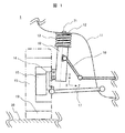
- FIG. 1 is a schematic view of the suspension device according to the first embodiment of the present invention.
- FIG. 1 is a view of the vehicle viewed from the front, and shows a front wheel (one wheel) located on the right side in the traveling direction of the vehicle.
- the MacPherson strut type suspension device 1 for automobiles has a strut 10 that connects the vehicle body 11 and the tire 19 as a pillar, a coil spring 13 that is suspended from the strut 10 and produces vehicle weight and damping resistance, and a strut 10 that is fastened to the strut 10 when a curve is formed. It is composed of a stabilizer 16 that compensates for rigidity against vehicle body twist and maintains the vehicle body posture, a knuckle 14 that fastens struts 10, and a lower arm 17 that is a structural member that determines the camber angle and caster angle fastened to the knuckle 14. .
- the strut 10 produces a damping force and supports the lateral force.
- One end side of the MacPherson strut type suspension device 1 for automobiles is connected to the vehicle body 11 via the strut 10 and the upper mount 12 fixed to the + Y side of the coil spring 13. Further, the other end side of the MacPherson strut type suspension device 1 for automobiles is connected to one end side of the lower arm 17 and is connected to the vehicle body 11.
- a bearing (not shown) is fixed to the knuckle 14, and the bearing supports the wheel hub 15 in a rollable manner.
- a wheel rim 18 is fixed to the wheel hub 15, and a tire 19 is fixed to the outer peripheral portion of the wheel rim 18.
- the wheel rim 18 and the tire 19 form a wheel.
- the tire 19 touches the ground 20 and transmits a driving force to the ground 20 to drive the vehicle.
- the lateral force acting during traveling is mainly supported by the struts 10 and the knuckle 14, and the displacement of the vehicle body is suppressed.
- the vibration caused by the input from the ground 20 or the input from the vehicle body 11 is attenuated by the strut 10 and the coil spring 13 moving linearly along the stroke center line 71.
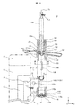
- FIG. 2 is a vertical side view of the double-cylinder strut type shock absorber viewed from the front direction of the vehicle body according to the first embodiment of the present invention
- FIG. 3 is a sectional view taken along line III-III'in FIG.
- the strut 10 has an inner cylinder 103 that slidably accommodates the piston 111, and an outer cylinder 104 arranged on the outer peripheral side of the inner cylinder 103.
- the outer cylinder 104 is made of a gravity cast body, and the inner cylinder 103 is housed inside.
- the inner cylinder 103 and the outer cylinder 104 are arranged concentrically about the stroke center line 71, which is the sliding axis of the piston 111.
- a reservoir chamber 122 is formed between the inner cylinder 103 and the outer cylinder 104.
- a piston rod 102 is connected to the piston 111 to form a cushioning mechanism.
- the shock absorber is housed in a tubular inner cylinder 103.
- An oil seal 108 and a rod guide 109 are provided at the tips of the inner cylinder 103 and the outer cylinder 104 in the + Y direction.
- the tip side of the outer cylinder 104 is molded so that the shaft length is longer than the shaft length of the inner cylinder 103, and the oil seal 108 and the rod guide 109 are stored in this portion.
- the rod guide 109 is press-fitted and fixed to the tip of the inner cylinder 103 in the + Y direction.
- An integrated outer cylinder bottom plate 105 is molded at the bottom end in the Y-axis direction. Similar to the tip side, the shaft length of the bottom end side of the outer cylinder 104 is longer than the shaft length of the inner cylinder 103.
- the bottom valve 114 is stored in this portion.
- An opening is formed in the portion of the outer cylinder tip plate 104a on one end side of the outer cylinder 104, and an oil seal 108, a rod guide 109, an inner cylinder 103, and a bottom valve 114 are provided.
- the oil seal 108, the rod guide 109, the inner cylinder 103, and the bottom valve 114 are crimped and fixed by the outer cylinder tip plate 104a integrated with the tip of the outer cylinder 104 in the + Y direction, and the oil seal 108, the rod guide 109,
- the compression residual axial force transmitted in the order of the inner cylinder 103, the bottom valve 114, and the outer cylinder bottom plate 105 is applied.
- the inner cylinder 103 is filled with a liquid (not shown) such as oil, and the reservoir chamber 122 is filled with a predetermined amount of nitrogen gas (not shown) together with the liquid.
- the oil and nitrogen gas are sealed with a crimped and fixed oil seal 108.
- the center of the opening on one end side of the outer cylinder 104 is coaxial with the stroke center line 71 of the piston rod 102. As a result, the assembling property between the outer cylinder 104 and the piston rod 102 can be improved.
- the piston 111 is coupled to the bottom end of the piston rod 102 in the + Y direction.
- the tip of the piston rod 102 penetrates the oil seal 108 and the rod guide 109, extends to the tip of the outer cylinder 104 in the + Y direction, and is connected to the vehicle body 11 via the upper mount 12 shown in FIG. There is.
- a stabilizer bracket 106 that is integrally molded with the outer peripheral surface and fastens the stabilizer 16, a spring seat 107 that is fixed to the outer peripheral surface and supports the coil spring 13, and a knuckle that is integrally molded on the outer peripheral surface and fastened.
- Knuckle bracket fastening plates 110a and 110b (knuckle mounting portions) are provided.
- the knuckle bracket fastening plates 110a and 110b at both ends in the X direction are integrally molded into the outer cylinder 104 so as to be separated from each other in a width across flats and extend toward the outside of the vehicle body in the ⁇ Z direction, and the bolt fastening holes 110c are formed.
- the knuckle 14 is fastened and fixed to the knuckle 14 by the threaded bolt.
- the pair of knuckle bracket fastening plates 110a and 110b project in one direction from the outer surface of the outer cylinder 104, and the wide surfaces face each other, and the wide surfaces are provided along the axial direction of the outer cylinder 104.
- the knuckle 14 is connected to the vehicle body 11 via the strut 10.
- the piston 111 is housed in the inner cylinder 103, and the inside of the inner cylinder 103 is separated into an upper chamber 120 and a lower chamber 121.
- the piston 111 is provided with one or more piston orifices 111a, a piston check valve 112, and an extension side damping valve 113.
- the piston rod 102 is connected to the piston 111 and goes in and out of the inner cylinder 103.
- the damping force when the piston rod 102 strokes in the extension direction (+ Y direction) along the stroke center line 71 passes through the piston orifice 111a and the extension side damping valve 113 when the liquid flows from the upper chamber 120 to the lower chamber 121. By doing so, the distribution resistance is loaded and created.
- the bottom valve 114 is provided with one or more bottom valve orifices 114a, a bottom valve check valve 115, and a contraction side damping valve 116.
- the piston rod 102 strokes in the extension direction (+ Y direction) along the stroke center line 71, the liquid flows from the reservoir chamber 122 to the lower chamber 121 through the bottom valve orifice 114a by the bottom valve check valve 115. To do.
- the damping force when the piston rod 102 strokes in the contraction direction (-Y direction) along the stroke center line 71 is the bottom valve orifice 114a and the contraction side damping valve 116 when the liquid flows from the lower chamber 121 into the reservoir chamber 122. It is created by loading the distribution resistance by passing through.
- FIG. 3 is a cross-sectional view taken along the line III-III'in FIG.
- the cross section of the line III-III' is an orthogonal cross section at an arbitrary position in the axial direction of the outer cylinder 104 orthogonal to the stroke center line 71 of the piston rod 102.
- the point on the stroke center line 71 is defined as the stroke center point 71a.
- a line that passes through the stroke center point 71a (stroke center line 71), coincides with the inside and outside of the vehicle, and extends in the Z direction as a boundary between the inside and outside of the vehicle is defined as a virtual line 191.
- the virtual line 191 is a line parallel to the bolt fastening hole center axis 194 passing through the center of the bolt fastening holes 110c formed in the knuckle bracket fastening plates 110a and 110b.
- the virtual line 191 is a line orthogonal to the rotation axis of the wheel.
- the knuckle fastening center point 72a is located on the bolt fastening hole center axis 194.
- the cross-sectional area of the outer cylinder 104 in the virtual area I192 is defined.
- a i1 is larger than the cross-sectional area A o1 of the outer cylinder 104 in the virtual area II 193 (cross-sectional area A i1 > cross-sectional area A o 1 ).
- the cross-sectional area of the outer cylinder 104 is relative to the stroke center line 71 (center axis). It is divided into one side in the radial direction and the other side in the radial direction, and the cross-sectional area A o1 on the one side in the radial direction of the outer cylinder 104 is smaller than the cross-sectional area A o1 on the other side in the radial direction.
- the boundary between the one side in the radial direction and the other side in the radial direction with respect to the stroke center line 71 (center axis) is a plane orthogonal to the rotation axis of the wheel.
- the maximum distance between the outer circumference of the outer cylinder 104 and the interface between one side in the radial direction and the other side in the radial direction in the orthogonal cross section at an arbitrary position in the axial direction of the stroke center line 71 (central axis) is one in the radial direction.
- the side is shorter.
- the cross-sectional area Ai1 and the cross-sectional area Ao1 may include the cross-sectional area of the stabilizer bracket 106.
- the lateral force in the outward direction of the vehicle is shown as the lateral force F tZ1 .
- the magnitude and direction of the lateral force F tZ1 change randomly from moment to moment depending on the traveling conditions.
- the strut 10 is fastened to the knuckle 14 via the knuckle bracket fastening plates 110a and 110b to serve as a fixing portion for the lateral force F tZ1 , and the reaction force F bZ1 acts on the knuckle bracket fastening plates 110a and 110b and the outer cylinder 104 in the vicinity. ..
- the knuckle fastening center line 72 in which the reaction force F bZ1 is generated is not coaxial with respect to the stroke center line 71 on which the lateral force F tZ1 acts, and is offset by a distance l b1 in the Z direction.
- the strut 10 is bent and deformed by the lateral force F tZ1 .
- a bending moment M tZ1 of the cantilever is generated with the vicinity of the piston rod 102 side end as the root.
- the bending moment M tZ1 generated at this time is the sum of the bending moment generated by the lateral force F tZ1 and the bending moment generated by the offset of the lateral force F tZ1 and the reaction force F bZ1 .
- the moment of inertia of area which is one of the parameters that determine the flexural rigidity, can be effectively expanded.
- the moment of inertia of area is proportional to the fourth power of the diameter.
- the distance l c1 is the closest position between the outer cylinder 104 and the wheel rim 18 or the tire 19, and the distance l c1 is determined so that the tire chains and wheels do not come into contact with the outer cylinder 104 when the tire chains are attached or the wheels are inch-up. There is a need.
- the moment of inertia of area of the outer cylinder 104 is a value determined by the entire cross-sectional shape. Therefore, in this embodiment, the point on the stroke center line 71 in the orthogonal cross section is defined as the stroke center point 71a, and the distance from the stroke center point 71a in the virtual area I192 to the radial outer surface of the outer cylinder 104 is defined as the distance li11.
- the distance l o11 to the radial outer surface of the outer cylinder 104 in the virtual region II193 on the Z axis which is the clearance, is set to a value equal to or less than the distance l c1 (distance l o11 ⁇ distance l c1 ).
- the outer cylinder 104 in the virtual area I192 which has relatively few restrictions on the outer shape, is suppressed while suppressing the expansion of the outer cylinder 104 in the virtual area II193 inside the vehicle.
- the outer shape is enlarged.
- the thickness of the outer cylinder 104 on the distance l i11 is thicker than the thickness of the outer cylinder 104 on the distance l o11.
- the cross-sectional area A i1 of the outer cylinder 104 in the virtual area I192 is larger than the sectional area A o1 of the outer cylinder 104 in the virtual area II193 in this embodiment, the necessary moment of inertia
- the bending rigidity can be improved by securing the distance, and the outer cylinder 104 can be set to a distance lc1 or more so as not to interfere with the wheel rim 18 or the tire 19, and the clearance can be secured.
- the magnitude relation between the sectional area A o1 of the outer tube 104 of the outer cylinder 104 of the cross-sectional area A i1 and the virtual region II193 in the virtual region I192, the second moment of the outer cylinder 104 in the virtual area I192 I i1 Can also be defined as being greater than the moment of inertia of inertia I o1 of the outer cylinder 104 in the virtual area II193 (second moment of inertia I i1 > second moment of inertia I o 1 ).
- the geometrical moment of inertia of the outer cylinder 104 is set to the stroke center line 71 (central axis).
- the relationship between the cross-sectional area A i1 sectional area A o1, the relationship between the second moment I i1 and second moment I o1 is the spring seat 107 and the knuckle bracket fastening plate 110a, and 110b (knuckle mounting portion) It is an arbitrary position in the axial direction of the outer cylinder 104 provided between the two, and this arbitrary position in the axial direction includes the closest position (distance lc1 ) between the outer cylinder 104 and the wheel rim 18 or the tire 19.
- the flexural rigidity can be secured.
- the distance to the outer surface in the radial direction, the distance to the inner surface in the radial direction, the thickness, or any of the relationships with respect to the outer cylinder 104 on the arbitrary axis in the radial direction passing through the stroke center point 71a is satisfied. It does not exclude the absence.
- the cross-sectional shape of the inner cylinder 103 a shape close to a perfect circular pipe is preferable. This is because the inner cylinder 103 becomes a cylinder and the piston 111 slides linearly on the inner surface of the inner cylinder 103. This is because the inner cylinder 103 and the piston 111 need to be in close contact with each other and a damping medium such as oil needs to flow through the piston orifice 111a, which requires airtightness.
- the cross-sectional shape of the inner cylinder 103 is any shape such as an ellipse or a polygon.
- the relationship between the cross-sectional area, the moment of inertia of area, the distance, and the thickness of the outer cylinder 104 may be established at least within the range in the Y direction facing the wheel rim 18 and the tire 19 shown in FIG.
- the present invention does not exclude that it is established only in a part of the above-mentioned range and that it is established in the entire area of the outer cylinder 104 in the Y direction and a part of the wheel rim 18 and the tire 19 in the Y direction that does not face each other. ..
- FIG. 4 is a diagram showing a modification 1 in the cross-sectional shape of FIG.
- the same components as those in FIG. 3 are designated by the same reference numerals, and detailed description thereof will be omitted.
- the cross-sectional shape of the outer cylinder 204 shown in FIG. 4 is a shape obtained by removing the stabilizer bracket 106 from the cross-sectional shape of the outer cylinder 104 shown in FIG.
- the cross section of the outer cylinder 204 has a shape close to an ellipse, and is a shape that satisfies all the relationships of the cross-sectional area, the moment of inertia of area, the distance, and the thickness described in FIG.
- FIG. 5 is a diagram showing a modification 2 in the cross-sectional shape of FIG.
- the cross section of the outer cylinder 304 shown in FIG. 5 has a shape close to an egg-shaped circle.
- the configuration of FIG. 5 does not satisfy the relationship of the cross-sectional area described in FIG. 3 and the relationship of the distance and the thickness in a part of the region, but the moment of inertia of area satisfies the above-mentioned relationship and the effect in FIG. It is a cross-sectional shape that can exhibit.
- the outer cylinder 304 is arranged closer to the inside of the vehicle in the + Z direction, and the cross-sectional area in the virtual area I192 is larger than the cross-sectional area in the virtual area II193. With this configuration, it is possible to improve the bending rigidity by expanding the outer shape of the outer cylinder while ensuring the clearance between the wheel rim 18 or the tire 19 and the outer cylinder 304.
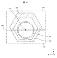
- FIG. 6 is a diagram showing a modification 3 in the cross-sectional shape of FIG.
- the cross section of the outer cylinder 404 shown in FIG. 6 has a shape close to a hexagon, and is a shape that satisfies all the relationships of the cross-sectional area, the moment of inertia of area, the distance, and the thickness described in FIG.
- the outer cylinder 404 is arranged closer to the inside of the vehicle in the + Z direction, and the cross-sectional area in the virtual area I192 is larger than the cross-sectional area in the virtual area II193. With this configuration, it is possible to improve the bending rigidity by expanding the outer shape of the outer cylinder while ensuring the clearance between the wheel rim 18 or the tire 19 and the outer cylinder 404.
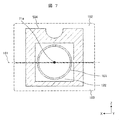
- FIG. 7 is a diagram showing a modified example 4 in the cross-sectional shape of FIG.
- the cross section of the outer cylinder 504 shown in FIG. 7 is close to a quadrangle and has a partial shape, and has a radial recess in the virtual area I592.
- the relationship between the distance and the thickness is not satisfied in the recessed portion, but the cross-sectional area and the moment of inertia of area are satisfied in relation to each other.
- the outer cylinder 504 is arranged closer to the inside of the vehicle in the + Z direction, and the cross-sectional area in the virtual area I192 is larger than the cross-sectional area in the virtual area II193. With this configuration, it is possible to improve the bending rigidity by expanding the outer shape of the outer cylinder while ensuring the clearance between the wheel rim 18 or the tire 19 and the outer cylinder 504.
- FIG. 8 is a diagram showing a modified example 5 in the cross-sectional shape of FIG.
- the cross section of the outer cylinder 604 shown in FIG. 8 has a shape close to that of a petal, and has a shape that satisfies all the relationships of the cross-sectional area, the moment of inertia of area, the distance, and the thickness.
- the outer cylinder 604 is arranged closer to the inside of the vehicle in the + Z direction, and the cross-sectional area in the virtual area I192 is larger than the cross-sectional area in the virtual area II193. With this configuration, it is possible to improve the bending rigidity by expanding the outer shape of the outer cylinder while ensuring the clearance between the wheel rim 18 or the tire 19 and the outer cylinder 604.
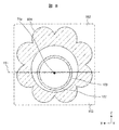
- FIG. 9 is a diagram showing a modification 6 in the cross-sectional shape of FIG.
- the cross section of the outer cylinder 704 shown in FIG. 9 has a shape similar to that of a gear, and has a shape that satisfies all the relationships of the cross-sectional area, the moment of inertia of area, the distance, and the thickness.
- the outer cylinder 704 is arranged closer to the inside of the vehicle in the + Z direction, and the cross-sectional area in the virtual area I192 is larger than the cross-sectional area in the virtual area II193. With this configuration, it is possible to improve the bending rigidity by expanding the outer shape of the outer cylinder while ensuring the clearance between the wheel rim 18 or the tire 19 and the outer cylinder 704.
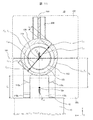
- FIG. 10 is a vertical side view of the double-cylinder strut type shock absorber viewed from the front direction of the vehicle body according to the second embodiment of the present invention
- FIG. 11 is a sectional view taken along line XI-XI'in FIG.
- the same components as those in the first embodiment are designated by the same reference numerals, and detailed description thereof will be omitted.
- the difference between the second embodiment and the first embodiment is that the stabilizer bracket 206 attached to the strut 10 is arranged in the + Z direction inside the vehicle. That is, the stabilizer bracket 206 provided on the outer cylinder is provided on the opposite side of the knuckle bracket fastening plates 110a and 110b (knuckle mounting portion) with the outer cylinder 104 interposed therebetween.
- the stabilizer bracket 206 is on the lateral force reaction force line 190 generated by the lateral force F tZ1 and the reaction force F bZ1 and is on the outer cylinder in the virtual area I192. It was placed on the radial outer surface of 104. With such an arrangement, the cross-sectional area and the moment of inertia of area of the outer cylinder 104 in the virtual area I192 can be improved, and the bending rigidity of the strut 10 with respect to the lateral force F tZ1 can be improved. As shown in FIG.
- the stabilizer bracket 206 is preferably arranged so that the central position in the X direction coincides with the lateral force reaction force action line 190 because the moment of inertia of area can be maximized. However, even if the center position of the stabilizer bracket 206 in the X direction does not coincide with the lateral force reaction line 190, the flexural rigidity can be improved if the stabilizer bracket 206 is arranged in the virtual area I192. .. As shown in FIG. 10, the stabilizer bracket 206 is preferably arranged in a range facing the wheel rim 18 and the tire 19. In this case, the stabilizer bracket 206 may be arranged in the entire length in the Y direction or a part of the area facing the wheel rim 18 and the tire 19. In the present invention, it is not excluded that the stabilizer bracket 206 is arranged at a position in the Y direction that does not face the wheel rim 18 and the tire 19.
- the stabilizer bracket 106 is arranged on the front side of the vehicle. Since the knuckle bracket fastening plate 110a and the knuckle bracket fastening plate 110b are generally arranged on the outside of the vehicle, it is necessary to manufacture struts having different specifications for the left and right wheels at the arrangement position of the stabilizer bracket 106 on the struts 10.
- the strut 10 can be shared by the left and right wheels, and the cost of the strut 10 can be reduced. Can be done.
- an aluminum alloy material is applied as a constituent material of the outer cylinder 104.
- the strut 10 is made lighter by applying a low-density aluminum alloy material to the steel material in addition to improving the moment of inertia of area by enlarging the outer cylinder 104. It becomes possible to change.
- the constituent material any composite material such as steel material, magnesium alloy material, titanium alloy material, resin material, carbon-based material and glass-based material may be used.
- the inner cylinder 103, the outer cylinder 104, the stabilizer bracket 106, and the spring seat 107 are made of the same material.
- the present invention does not exclude the inner cylinder 103, the outer cylinder 104, the stabilizer bracket 106, the spring seat 107, the knuckle bracket fastening plate 110a and the knuckle bracket fastening plate 110b being made of different materials.
- the inner cylinder 103, the outer cylinder 104, the stabilizer bracket 106, the spring seat 107, the knuckle bracket fastening plate 110a and the knuckle bracket fastening plate 110b have surfaces such as plating, painting, alumite, and carburizing for the purpose of preventing rust and improving surface hardness. Treatment or heat treatment may be performed. The same applies to the modified examples shown in FIGS. 4 to 11.
- the outer cylinder 104 may be formed into a tube shape by an electric sewing method from a member that has been preliminarily unevenly walled by a dissimilar material joining method using a tailored blank method or a flow forming method. Further, the outer cylinder 104 may be molded by three-dimensional modeling. The present invention does not exclude molding by cutting, forging, extrusion, drawing, or the like.
- the stabilizer bracket 106, the knuckle bracket fastening plate 110a and the knuckle bracket fastening plate 110b molded on the outer cylinder 104 are integrally cast to reduce the number of parts.
- the spring seat 107 is a separate part and is welded and fixed, but any method such as fitting, press-fitting, brazing, bonding, bolt fastening, crimping, injection molding, etc. May be fixed by. Further, the spring seat 107 may be molded by integral casting.
- the stabilizer bracket 106 and the knuckle bracket fastening plates 110a and 110b are integrally cast and molded, but they are fixed as separate parts by any method such as welding, fitting, press fitting, brazing, bonding, bolt fastening, crimping, and injection molding. Is also good.
- the stabilizer bracket 106 and the spring seat 107 may be integrated, and the knuckle bracket fastening plate 110a and the knuckle bracket fastening plate 110b may be integrated.
- the knuckle bracket fastening plates 110a and 110b are removed from the outer cylinder 104, and the outer cylinder 104 is directly welded, fitted, press-fitted, brazed, bonded, bolted, crimped, to the knuckle 14. It may be fixed by a construction method such as an injection molding mold. In that case, some kind of mark such as a protrusion, a dent, or an engraving may be formed on the strut 10 or the outer surface of the outer cylinder 104 so that the vehicle mounting position of the outer cylinder 104 can be visually determined. The same applies to the modified examples shown in FIGS. 4 to 11.
- the present invention is not limited to that described in the first and second embodiments, and a form in which a plurality of pistons are switched with an actuator to switch damping performance with respect to a road surface input frequency, a solenoid stored or attached to an outer cylinder, or the like. It may be a control type double cylinder type strut type shock absorber and a shock absorber of a type that switches the damping performance by some energy from the outside of the above.
- a double-cylinder strut type shock absorber and a shock absorber using air, a magnetic viscous fluid, an electrorheological fluid, or the like may be used.
- the present invention may be a single-cylinder strut-type shock absorber or an inverted single-cylinder or double-cylinder strut-type shock absorber and shock absorber in which a rod is fastened to the knuckle side.
- a shock absorber having a piston 111 and a piston rod 102 connected to the piston 111, a tubular inner cylinder 103 accommodating the buffer mechanism, and an outer cylinder accommodating the inner cylinder 103.
- the outer cylinder 104 is provided with a cylinder 104, and has a pair of knuckle bracket fastening plates 110a and 110b that are provided integrally with the outer cylinder 104 and project from the outer surface of the outer cylinder 104 in one direction, and fasten the pair of knuckle brackets.
- a strut type shock absorber in which the wide surfaces of the plates 110a and 110b face each other and the wide surfaces are provided along the axial direction of the outer cylinder 104.
- the inside of the vehicle passes through the stroke center line 71 and is defined as a virtual line 191 that coincides with the inside and outside of the vehicle.
- virtual area I192 when the vehicle outer side of the virtual area II193, characterized by being larger than the cross-sectional area a o1 of the outer tube 104 in the virtual area II193 sectional area a i1 of the outer tube 104 in the virtual area I192.
- a double-cylinder strut type shock absorber can be provided.
- the present invention is not limited to each of the above-described embodiments, and includes various modifications.
- the above-described embodiment has been described in detail in order to explain the present invention in an easy-to-understand manner, and is not necessarily limited to the one including all the described configurations.
- it is possible to replace a part of the configuration of one embodiment with the configuration of another embodiment and it is also possible to add the configuration of another embodiment to the configuration of one embodiment.
- Oil seal 109 ... Rod guide, 110a, 110b ... Knuckle bracket fastening plate, 110c ... Bolt fastening hole, 111 ... Piston, 111a ... Piston orifice, 112 ... Piston check valve, 113 ... Extension side damping valve, 114 ... Bottom valve, 114a ... Bottom valve orifice, 115 ... Bottom valve check valve, 116 ... Shrink side damping valve, 120 ... Upper chamber, 121 ... Lower chamber, 122 ... Reservoir Room, 190 ... Lateral force reaction line, 191 ... Virtual line, 192 ... Virtual area I, 193 ... Virtual area II
Landscapes
- Engineering & Computer Science (AREA)
- Mechanical Engineering (AREA)
- General Engineering & Computer Science (AREA)
- Vehicle Body Suspensions (AREA)
- Fluid-Damping Devices (AREA)
Abstract
Description
[本発明の実施態様例]
本発明の実施態様の一例として、例えば、ピストン111と、ピストン111に連結されたピストンロッド102を有する緩衝機構と、緩衝機構を収容する筒状の内筒103と、内筒103を収容する外筒104とを備え、外筒104は、外筒104と一体に設けられ、外筒104の外面から一方向側に突出した一対のナックルブラケット締結板110a,110bを有し、一対のナックルブラケット締結板110a,110bは、それぞれ幅広面を対向させ、前記幅広面が外筒104の軸方向に沿って設けられたストラット型ショックアブソーバにおいて、
前記ピストンロッド102のストローク中心線71に直交する外筒104の軸方向任意位置での直交断面において、ストローク中心線71を通り、車両内側と外側に一致した仮想線191を境界に、車両内側を仮想領域I192、車両外側の仮想領域II193とした場合、仮想領域I192における外筒104の断面積Ai1を仮想領域II193における外筒104の断面積Ao1より大きくしたことを特徴とする。
Claims (17)
- ピストンと、前記ピストンに連結されたピストンロッドを有する緩衝機構と、前記緩衝機構を収容する筒状の内筒と、前記内筒を収容する外筒とを備え、
前記外筒は、前記外筒と一体に設けられ、前記外筒の外面から一方向側に突出した一対のナックル取付け部を有し、
前記一対のナックル取付け部は、それぞれ幅広面を対向させ、前記幅広面が前記外筒の軸方向に沿って設けられたシリンダ装置において、
前記ピストンロッドのストローク中心線に直交する前記外筒の軸方向任意位置での直交断面において、前記ストローク中心線を通り、車両内側と外側に一致した仮想線を境界に、車両内側を仮想領域I、車両外側の仮想領域IIとした場合、前記仮想領域Iにおける前記外筒の断面積を前記仮想領域IIにおける前記外筒の断面積より大きくしたことを特徴とするシリンダ装置。 - ピストンと、前記ピストンに連結されたピストンロッドを有する緩衝機構と、前記緩衝機構を収容する筒状の内筒と、前記内筒を収容する外筒とを備え、
前記外筒は、前記外筒と一体に設けられ、前記外筒の外面から一方向側に突出した一対のナックル取付け部を有し、
前記一対のナックル取付け部は、それぞれ幅広面を対向させ、前記幅広面が前記外筒の軸方向に沿って設けられたシリンダ装置において、
前記ピストンロッドのストローク中心線に直交する前記外筒の軸方向任意位置での直交断面において、前記ストローク中心線を通り、車両内側と外側に一致した仮想線を境界に、車両内側を仮想領域I、車両外側の仮想領域IIとした場合、前記仮想領域Iにおける前記外筒の断面2次モーメントを前記仮想領域IIにおける前記外筒の断面2次モーメントより大きくしたことを特徴とするシリンダ装置。 - 請求項1または2に記載のシリンダ装置において、
ホイールリムの外周部にタイヤが固定されて車輪が構成され、
前記外筒の軸方向任意位置は、前記車輪のタイヤもしくはホイールリムの最接近位置を含むことを特徴とするシリンダ装置。 - 請求項1または2に記載のシリンダ装置において、
ホイールリムの外周部にタイヤが固定されて車輪が構成され、
前記仮想線は、前記車輪の回転軸と直交する線であることを特徴とするシリンダ装置。 - 請求項4に記載のシリンダ装置において、
前記直交断面における前記ストローク中心線上の点をストローク中心点とし、
前記仮想領域Iにおける前記ストローク中心点から前記外筒の径方向外表面までの距離を距離li11とし、前記ストローク中心点を基準として前記距離li11と点対称位置であり前記仮想領域IIにおける前記ストローク中心点から前記外筒の径方向外表面までの距離を距離lo11とした時、前記距離li11を前記距離lo11よりも長くしたことを特徴とするシリンダ装置。 - 請求項5に記載のシリンダ装置において、
前記距離li11上における前記外筒の厚さは、前記距離lo11上における前記外筒の厚さよりも厚くしたことを特徴とするシリンダ装置。 - 請求項1または2に記載のシリンダ装置において、
前記外筒には、コイルスプリングを支持するスプリングシートが設けられ、前記軸方向任意位置は、前記ナックル取付け部と前記スプリングシートの間に設けられることを特徴とするシリンダ装置。 - 請求項1または2に記載のシリンダ装置において、
前記外筒の一端側の開口中心は、前記ストローク中心線と同軸となっていることを特徴とするシリンダ装置。 - 請求項1または2に記載のシリンダ装置において、
前記外筒にスタビブラケットを備え、
前記スタビブラケットは、前記外筒を挟んで前記ナックル取付け部の反対側に備えられたことを特徴とするシリンダ装置。 - 筒状の外筒と、
前記外筒の一端から突出し、ストロークするロッドと、からなるシリンダ装置において、
前記外筒の前記ロッドの中心軸の軸方向任意の位置での直交断面において、前記中心軸に対する径方向一側と径方向他側とに分け、前記外筒の前記径方向一側の断面積を前記径方向他側の断面積より小さくしたことを特徴とするシリンダ装置。 - 筒状の外筒と、
前記外筒の一端から突出し、ストロークするロッドと、からなるシリンダ装置において、
前記外筒の前記ロッドの中心軸の軸方向任意の位置での直交断面において、前記中心軸に対する径方向一側と径方向他側に分け、前記外筒の前記径方向一側の断面2次モーメントを前記径方向他側の断面2次モーメントより小さくしたことを特徴とするシリンダ装置。 - 請求項10または11に記載のシリンダ装置において、
前記外筒の前記ロッドの中心軸の軸方向任意の位置は、車輪を構成するタイヤまたはホイールリムの最接近位置を含むことを特徴とするシリンダ装置。 - 請求項12に記載のシリンダ装置において、
前記中心軸に対する前記径方向一側と前記径方向他側の境界は、前記車輪の回転軸と直交する面であることを特徴とするシリンダ装置。 - 請求項13に記載のシリンダ装置において、
前記中心軸の軸方向任意の位置での直交断面における前記外筒外周と、前記径方向一側と前記径方向他側との境界面からの垂線の最大距離は、前記径方向一側の方が短いことを特徴とするシリンダ装置。 - 請求項10乃至14のいずれか1項に記載のシリンダ装置において、
前記外筒は、重力鋳造体からなることを特徴とするシリンダ装置。 - 請求項12に記載のシリンダ装置において、
前記外筒は、前記外筒と一体に設けられ、前記外筒の外面から一方向側に突出した一対のナックル取付け部を有し、
前記外筒には、前記シリンダ装置が設けられる車体を支持するスプリングを受けるスプリングシートが設けられ、前記軸方向任意は、前記ナックル取付け部と前記スプリングシートの間に設けられることを特徴とするシリンダ装置。 - 請求項10乃至16のいずれか1項に記載のシリンダ装置において、
前記外筒の一端側の開口は、前記ロッドのストローク方向の中心軸と同軸となることを特徴とするシリンダ装置。
Priority Applications (4)
| Application Number | Priority Date | Filing Date | Title |
|---|---|---|---|
| CN202080011934.9A CN113518722B (zh) | 2019-03-08 | 2020-02-14 | 缸筒装置 |
| KR1020217024651A KR102553157B1 (ko) | 2019-03-08 | 2020-02-14 | 실린더 장치 |
| DE112020000362.0T DE112020000362B4 (de) | 2019-03-08 | 2020-02-14 | Zylindervorrichtung |
| US17/424,961 US12151533B2 (en) | 2019-03-08 | 2020-02-14 | Cylinder device |
Applications Claiming Priority (2)
| Application Number | Priority Date | Filing Date | Title |
|---|---|---|---|
| JP2019-042473 | 2019-03-08 | ||
| JP2019042473A JP7182495B6 (ja) | 2019-03-08 | 2019-03-08 | シリンダ装置 |
Publications (1)
| Publication Number | Publication Date |
|---|---|
| WO2020184058A1 true WO2020184058A1 (ja) | 2020-09-17 |
Family
ID=72353670
Family Applications (1)
| Application Number | Title | Priority Date | Filing Date |
|---|---|---|---|
| PCT/JP2020/005740 Ceased WO2020184058A1 (ja) | 2019-03-08 | 2020-02-14 | シリンダ装置 |
Country Status (6)
| Country | Link |
|---|---|
| US (1) | US12151533B2 (ja) |
| JP (1) | JP7182495B6 (ja) |
| KR (1) | KR102553157B1 (ja) |
| CN (1) | CN113518722B (ja) |
| DE (1) | DE112020000362B4 (ja) |
| WO (1) | WO2020184058A1 (ja) |
Families Citing this family (3)
| Publication number | Priority date | Publication date | Assignee | Title |
|---|---|---|---|---|
| CN115943101A (zh) | 2020-08-27 | 2023-04-07 | 株式会社电装 | 车辆用显示装置 |
| JP7483019B2 (ja) * | 2020-09-04 | 2024-05-14 | 日立Astemo株式会社 | 緩衝器 |
| CN114233792A (zh) * | 2021-12-18 | 2022-03-25 | 新乡市新华液压机械有限公司 | 一种用于油气弹簧的活塞杆结构 |
Citations (3)
| Publication number | Priority date | Publication date | Assignee | Title |
|---|---|---|---|---|
| JPH03292427A (ja) * | 1990-04-09 | 1991-12-24 | Atsugi Unisia Corp | 緩衝器 |
| JP2001182772A (ja) * | 1999-10-15 | 2001-07-06 | Showa Corp | 倒立型油圧緩衝器 |
| JP2002089606A (ja) * | 2000-09-12 | 2002-03-27 | Kayaba Ind Co Ltd | 油圧緩衝器の外筒形状 |
Family Cites Families (23)
| Publication number | Priority date | Publication date | Assignee | Title |
|---|---|---|---|---|
| US2710077A (en) * | 1952-01-16 | 1955-06-07 | Vibratrol Inc | Hydraulic shock absorber |
| FR1483611A (ja) * | 1965-06-18 | 1967-09-06 | ||
| US4306638A (en) * | 1978-07-14 | 1981-12-22 | General Motors Corporation | Shock absorber for automotive suspension |
| JPH07257132A (ja) * | 1994-03-18 | 1995-10-09 | Nissan Motor Co Ltd | 車両用懸架装置 |
| JP3623278B2 (ja) * | 1995-04-28 | 2005-02-23 | トヨタ自動車株式会社 | ブシュ構造 |
| JP3695726B2 (ja) * | 1996-10-16 | 2005-09-14 | カヤバ工業株式会社 | スタビライザブラケットの油圧緩衝器への結合構造 |
| JPH11182610A (ja) * | 1997-12-24 | 1999-07-06 | Unisia Jecs Corp | ストラット型サスペンションの複筒式緩衝器 |
| US6692012B2 (en) * | 2001-03-09 | 2004-02-17 | Delphi Technologies, Inc. | Vehicle damper assembly and method |
| DE10115373C1 (de) * | 2001-03-28 | 2002-10-17 | Zf Sachs Ag | Gelenkstütze für ein Kolben-Zylinderaggregat |
| JP2003278756A (ja) * | 2002-03-27 | 2003-10-02 | Daido Metal Co Ltd | すべり軸受 |
| DE102006012086A1 (de) * | 2006-03-14 | 2007-09-20 | Muhr Und Bender Kg | Federbeinrohr aus flexibel gewalztem Blech |
| JP4908059B2 (ja) * | 2006-05-22 | 2012-04-04 | カヤバ工業株式会社 | ストラット型ショックアブソーバ |
| JP4328370B2 (ja) * | 2007-07-24 | 2009-09-09 | 本田技研工業株式会社 | 車両用サスペンション装置 |
| JP2010069962A (ja) * | 2008-09-16 | 2010-04-02 | Asahi Tec Corp | サスペンション部材 |
| EP2540534B1 (en) * | 2011-05-16 | 2014-10-29 | Nissan Motor Co., Ltd | Suspension structure, bush structure and suspension characteristic adjusting method |
| JP6546715B2 (ja) * | 2013-07-08 | 2019-07-17 | 株式会社ブリヂストン | ストラットマウント |
| JP6546716B2 (ja) * | 2013-07-08 | 2019-07-17 | 株式会社ブリヂストン | ストラットマウント |
| CN204921824U (zh) * | 2015-07-13 | 2015-12-30 | 上海金众汽车配件有限公司 | 一种缩、涨口式汽车减振器外筒 |
| DE102017218719B4 (de) * | 2017-10-19 | 2021-07-22 | Ford Global Technologies, Llc | Radaufhängung und Fahrzeug |
| US10385918B1 (en) * | 2018-07-23 | 2019-08-20 | Gm Global Technology Operations, Llc | Bearing with visco-metal layers reactive to increase dynamically clearance and minimum oil film thickness |
| KR20210077765A (ko) * | 2018-12-27 | 2021-06-25 | 히다치 아스테모 가부시키가이샤 | 완충기 |
| JP6533026B1 (ja) * | 2019-04-04 | 2019-06-19 | 株式会社ショーワ | 緩衝器 |
| WO2020235311A1 (ja) * | 2019-05-21 | 2020-11-26 | Kyb株式会社 | スプリングガイド及びサスペンション装置 |
-
2019
- 2019-03-08 JP JP2019042473A patent/JP7182495B6/ja active Active
-
2020
- 2020-02-14 KR KR1020217024651A patent/KR102553157B1/ko active Active
- 2020-02-14 WO PCT/JP2020/005740 patent/WO2020184058A1/ja not_active Ceased
- 2020-02-14 CN CN202080011934.9A patent/CN113518722B/zh active Active
- 2020-02-14 US US17/424,961 patent/US12151533B2/en active Active
- 2020-02-14 DE DE112020000362.0T patent/DE112020000362B4/de active Active
Patent Citations (3)
| Publication number | Priority date | Publication date | Assignee | Title |
|---|---|---|---|---|
| JPH03292427A (ja) * | 1990-04-09 | 1991-12-24 | Atsugi Unisia Corp | 緩衝器 |
| JP2001182772A (ja) * | 1999-10-15 | 2001-07-06 | Showa Corp | 倒立型油圧緩衝器 |
| JP2002089606A (ja) * | 2000-09-12 | 2002-03-27 | Kayaba Ind Co Ltd | 油圧緩衝器の外筒形状 |
Also Published As
| Publication number | Publication date |
|---|---|
| CN113518722A (zh) | 2021-10-19 |
| KR102553157B1 (ko) | 2023-07-10 |
| JP2020143764A (ja) | 2020-09-10 |
| KR20210102466A (ko) | 2021-08-19 |
| JP7182495B2 (ja) | 2022-12-02 |
| CN113518722B (zh) | 2024-02-09 |
| US12151533B2 (en) | 2024-11-26 |
| US20220088983A1 (en) | 2022-03-24 |
| DE112020000362B4 (de) | 2025-11-06 |
| DE112020000362T5 (de) | 2021-10-07 |
| JP7182495B6 (ja) | 2024-02-06 |
Similar Documents
| Publication | Publication Date | Title |
|---|---|---|
| CN214698940U (zh) | 用于阻尼器的延伸组件及该阻尼器 | |
| CN104203607B (zh) | 单壳式弹簧导杆 | |
| CN113518722B (zh) | 缸筒装置 | |
| JP2001047825A (ja) | 改良されたトルクロッド頂点部組み付け構造 | |
| US11981179B2 (en) | Suspension | |
| US20090218783A1 (en) | Wheel suspension for motor vehicles | |
| EP3297860B1 (en) | Link assembly for longitudinal arm vehicle suspension | |
| KR100902837B1 (ko) | 이종강관을 이용한 자동차의 후륜 현가장치용 튜브형 토션빔 | |
| CN203739567U (zh) | 一种汽车多连杆悬架纵托臂衬套 | |
| JP7502976B2 (ja) | 緩衝器 | |
| JP6994434B2 (ja) | ショックアブゾーバ | |
| US11840121B2 (en) | Suspension | |
| JP2024174829A (ja) | 車両用エアスプリングのためのスリーブおよびこれを含む車両用エアスプリング | |
| CN112930272A (zh) | 具有整体式基部的阻尼器 | |
| JP2005155793A (ja) | 油圧緩衝器 | |
| JP2019031267A (ja) | 車両用ナックル | |
| JP5455754B2 (ja) | アクスルハウジング | |
| JP6789874B2 (ja) | 車両用ショックアブゾーバ | |
| JP6793011B2 (ja) | 車両のサスペンション構造 | |
| CN114013233B (zh) | 车辆后悬架上控制臂及车辆 | |
| JP2006193013A (ja) | 車両用スタビライザ装置 | |
| JP5544216B2 (ja) | サスペンション装置 | |
| JP6514545B2 (ja) | ストラット式サスペンション装置 | |
| WO2024195430A1 (ja) | 溶接方法及び溶接構造 | |
| JP2024174828A (ja) | 車両用エアスプリングのためのスリーブおよびこれを含む車両用エアスプリング |
Legal Events
| Date | Code | Title | Description |
|---|---|---|---|
| 121 | Ep: the epo has been informed by wipo that ep was designated in this application |
Ref document number: 20770913 Country of ref document: EP Kind code of ref document: A1 |
|
| ENP | Entry into the national phase |
Ref document number: 20217024651 Country of ref document: KR Kind code of ref document: A |
|
| WWE | Wipo information: entry into national phase |
Ref document number: 112020000362 Country of ref document: DE |
|
| WWP | Wipo information: published in national office |
Ref document number: 112020000362 Country of ref document: DE |
|
| 122 | Ep: pct application non-entry in european phase |
Ref document number: 20770913 Country of ref document: EP Kind code of ref document: A1 |
|
| WWG | Wipo information: grant in national office |
Ref document number: 112020000362 Country of ref document: DE |