WO2020170561A1 - 異物除去装置 - Google Patents
異物除去装置 Download PDFInfo
- Publication number
- WO2020170561A1 WO2020170561A1 PCT/JP2019/048107 JP2019048107W WO2020170561A1 WO 2020170561 A1 WO2020170561 A1 WO 2020170561A1 JP 2019048107 W JP2019048107 W JP 2019048107W WO 2020170561 A1 WO2020170561 A1 WO 2020170561A1
- Authority
- WO
- WIPO (PCT)
- Prior art keywords
- work
- foreign matter
- outer peripheral
- peripheral surface
- roller
- Prior art date
- Legal status (The legal status is an assumption and is not a legal conclusion. Google has not performed a legal analysis and makes no representation as to the accuracy of the status listed.)
- Ceased
Links
Images

Classifications
-
- B—PERFORMING OPERATIONS; TRANSPORTING
- B08—CLEANING
- B08B—CLEANING IN GENERAL; PREVENTION OF FOULING IN GENERAL
- B08B7/00—Cleaning by methods not provided for in a single other subclass or a single group in this subclass
- B08B7/0028—Cleaning by methods not provided for in a single other subclass or a single group in this subclass by adhesive surfaces
-
- A—HUMAN NECESSITIES
- A47—FURNITURE; DOMESTIC ARTICLES OR APPLIANCES; COFFEE MILLS; SPICE MILLS; SUCTION CLEANERS IN GENERAL
- A47L—DOMESTIC WASHING OR CLEANING; SUCTION CLEANERS IN GENERAL
- A47L25/00—Domestic cleaning devices not provided for in other groups of this subclass
-
- A—HUMAN NECESSITIES
- A47—FURNITURE; DOMESTIC ARTICLES OR APPLIANCES; COFFEE MILLS; SPICE MILLS; SUCTION CLEANERS IN GENERAL
- A47L—DOMESTIC WASHING OR CLEANING; SUCTION CLEANERS IN GENERAL
- A47L25/00—Domestic cleaning devices not provided for in other groups of this subclass
- A47L25/005—Domestic cleaning devices not provided for in other groups of this subclass using adhesive or tacky surfaces to remove dirt, e.g. lint removers
-
- B—PERFORMING OPERATIONS; TRANSPORTING
- B08—CLEANING
- B08B—CLEANING IN GENERAL; PREVENTION OF FOULING IN GENERAL
- B08B7/00—Cleaning by methods not provided for in a single other subclass or a single group in this subclass
-
- B—PERFORMING OPERATIONS; TRANSPORTING
- B23—MACHINE TOOLS; METAL-WORKING NOT OTHERWISE PROVIDED FOR
- B23C—MILLING
- B23C3/00—Milling particular work; Special milling operations; Machines therefor
- B23C3/12—Trimming or finishing edges, e.g. deburring welded corners
-
- B—PERFORMING OPERATIONS; TRANSPORTING
- B23—MACHINE TOOLS; METAL-WORKING NOT OTHERWISE PROVIDED FOR
- B23Q—DETAILS, COMPONENTS, OR ACCESSORIES FOR MACHINE TOOLS, e.g. ARRANGEMENTS FOR COPYING OR CONTROLLING; MACHINE TOOLS IN GENERAL CHARACTERISED BY THE CONSTRUCTION OF PARTICULAR DETAILS OR COMPONENTS; COMBINATIONS OR ASSOCIATIONS OF METAL-WORKING MACHINES, NOT DIRECTED TO A PARTICULAR RESULT
- B23Q11/00—Accessories fitted to machine tools for keeping tools or parts of the machine in good working condition or for cooling work; Safety devices specially combined with or arranged in, or specially adapted for use in connection with, machine tools
Definitions
- the present invention relates to a foreign matter removing device.
- the present invention has been made in order to solve the above-mentioned conventional problems, and its main object is to provide a foreign matter removing device capable of efficiently removing foreign matter attached to a work.
- the foreign matter removing apparatus of the present invention is a foreign matter removing apparatus for removing foreign matter adhering to the outer peripheral surface of a work obtained by cutting the outer peripheral surface of a laminate formed by laminating a plurality of films with adhesive layers.
- the holding unit that holds the work so that the outer peripheral surface is exposed, a feeding roller that feeds the adhesive tape, a winding roller that winds the adhesive tape fed from the feeding roller, and the feeding roller.
- a foreign matter removing unit having a contact roller arranged between the winding roller and configured to be capable of pressing the adhesive tape against the work.
- the work is configured to be rotatable.
- the contact roller is configured to be movable back and forth following the shape and rotation of the work.
- the contact roller is an elastic roller having an elastic layer on its surface.
- the elastic surface layer of the elastic roller has a thickness of 4 mm or more.
- the pressing force of the contact roller is 0.2 MPa to 0.5 MPa.
- a foreign matter removing method removes foreign matter attached to the outer peripheral surface of a work obtained by cutting the outer peripheral surface of a laminated body formed by laminating a plurality of films with an adhesive layer, using the above foreign material removing device. A method of setting the work on the holding unit, rotating the work around a vertical axis of the work, and attaching an adhesive tape running on the foreign matter removing unit to the outer peripheral surface of the work.
- the foreign matter removing method comprises setting a work and then pressing an adhesive tape running on the foreign matter removing unit against the outer peripheral surface of the work while rotating the work around a vertical axis.
- the work is obtained by cutting the outer peripheral surface by bringing the cutting means into contact with the outer peripheral surface of the laminated body while rotating the laminated body around a vertical axis.
- the rotation speed of the work is faster than the rotation speed of the laminate when cutting the outer peripheral surface.
- the rotation direction of the work is opposite to the rotation direction of the stacked body when cutting the outer peripheral surface.
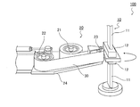
- FIG. 1 is a schematic perspective view of a foreign matter removing device according to one embodiment of the present invention.
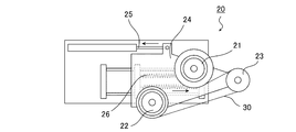
- FIG. 3 is a schematic side view of a foreign matter removing unit of the foreign matter removing apparatus according to one embodiment of the present invention.
- FIG. 3A is a photograph showing a state of the outer periphery of the work before removing foreign matter in Example 1
- FIG. 3B is a photograph showing the state of the outer periphery of the work after removing foreign matter in Example 1. It is a figure.
- FIG. 1 is a schematic perspective view of a foreign material removal device according to one embodiment of the present invention.
- the foreign matter removing apparatus 100 in the illustrated example includes a holding unit 10 and a foreign matter removing unit 20.
- the holding unit 10 is an element that holds the work W, and holds the work W such that the outer peripheral surface of the work W is exposed.
- the work W is obtained by cutting the outer peripheral surface of a laminated body formed by laminating a plurality of films with adhesive layers.
- the work W obtained by cutting the outer peripheral surface of the laminate has a large amount of foreign matter (cutting dust) attached to the outer peripheral surface thereof.
- the adhesive surface of the adhesive tape 30 which is run by the foreign matter removing unit 20 and has any appropriate adhesive force on the outer peripheral surface of the work W held by the holding unit 10 is the outer peripheral surface. By pressing, the foreign matter attached to the outer peripheral surface of the work W can be removed.
- a new portion of the adhesive surface of the adhesive tape 30 (the portion that is not used for foreign matter removal) can be sequentially supplied to the contaminated portion of the outer peripheral surface of the work W for supply.
- the foreign matter can be efficiently and automatically removed.
- the holding unit 10 is composed of two holding means having a shaft 11 and a pressing portion 12 arranged at the tip of the shaft 11.
- the work W can be pressed and held by the holding means arranged so that the pressing portions 12 face each other.
- the work W can be rotated about the vertical axis of the work W.
- the entire outer circumference of the work W can be efficiently and automatically cleaned. It is also advantageous in that a new portion of the adhesive surface of the adhesive tape 30 (a portion that has not been used for foreign matter removal) can always be supplied to the contaminated portion of the outer peripheral surface of the work W.
- the foreign matter removing unit 20 has a function of continuously running the long adhesive tape 30, and has a feeding roller 21, a winding roller 22, and a contact roller 23.
- the feeding roller 21, the winding roller 22, and the contact roller 23 may be arranged on one pedestal 24.
- a roller member such as a metal roller, a rubber roller or a resin roller
- the delivery roller 21 may be a roller having a drive source or a roller having no drive source.
- the feeding roller 21 does not have a drive source by itself, and is configured to rotate as the adhesive tape 30 runs.
- the feeding roller 21 may apply back tension to the adhesive tape 30 by means of a powder brake or the like.
- a roller member such as a metal roller, a rubber roller, or a resin roller can be used.
- the winding roller 22 has a drive source and rotates to wind the adhesive tape 30.
- the take-up roller 22 winds up the adhesive tape 30 that is fed and run by the contact roller 23 that is pressed against the rotating work W and wraps around the work W. By doing so, the amount of the adhesive tape 30 used can be reduced.
- the take-up roller 22 may apply back tension to the adhesive tape 30 by means of a powder brake or the like.
- the contact roller 23 is arranged between the feeding roller 21 and the take-up roller 22 (on the way of travel of the adhesive tape 30).
- the contact roller 23 may be arranged such that the traveling direction of the adhesive tape 30 is changed by the contact roller 23. Further, the contact roller 23 is preferably arranged such that the wrapping angle of the adhesive tape 30 is 45° to 200°, and more preferably 90° to 180°.
- the contact roller 23 can be configured to be movable back and forth, can be positioned apart from the work W before and after the foreign matter removing operation, and can be positioned on the outer peripheral surface of the work W during the foreign matter removing operation. It can move to abut. Further, the contact roller 23 is biased by a predetermined driving means so that the contact roller can be moved back and forth in accordance with the shape and rotation of the work W. By doing so, the contact roller can be positioned corresponding to the outermost rotation locus of the work W when removing the foreign matter, and the contact roller 23 keeps the adhesive tape 30 attached to the work W during the foreign matter removing operation. Can be pressed against.
- the contact roller 23 does not have a drive source, and may be configured to be pressed against the rotating work W and rotate around.
- the contact roller 23 may be arranged such that the rotation axis extends in the stacking direction of the works W.
- the back-and-forth movement of the contact roller 23 can be performed by any appropriate means.
- the back-and-forth movement of the contact roller 23 can be performed by using a driving means such as a cylinder (air cylinder, hydraulic cylinder, etc.), a spring, a motor, or the like.
- a driving means such as a cylinder (air cylinder, hydraulic cylinder, etc.), a spring, a motor, or the like.
- the feeding roller 21, the winding roller 22, and the contact roller 23 are arranged on one pedestal 24, and the pedestal 24 is moved back and forth, whereby the contact roller 23 is moved back and forth.
- a cylinder 25 and a spring 26 are combined to move the contact roller 23 (or the pedestal 24 on which the roller 23 is arranged) back and forth.
- the spring 26 is used for moving the contact roller 23 forward (moving toward the work W) and pressing the contact roller 23 against the work W, and the cylinder 25 (preferably an air cylinder) is used. It is used for rearward movement of the contact roller 23.
- the spring 26 may be used to press the contact roller 23 against the work W.
- the contact roller 23 is an elastic roller having an elastic layer on its surface. If an elastic roller is used, the roller surface is deformed when the contact roller 23 is pressed against the work W, and the contact roller 23 can be made to follow fine irregularities on the outer peripheral surface of the work well. 23 can be made to follow the inclined work. As a result, it is possible to prevent the occurrence of a gap between the contact roller 23 (substantially the adhesive tape 30) and the work W.
- the pressing pressure of the contact roller 23 is preferably 0.2 MPa to 0.5 MPa, more preferably 0.3 MPa to 0.4 MPa. With such a pressing pressure, the contact roller 23 is pressed against the work W, and the adhesive tape 30 is run between the contact roller 23 and the work W, so that foreign matter adhering to the outer periphery of the work W is better removed. In addition, the quality of the outer peripheral surface can be favorably maintained.
- the hardness (JIS A) of the elastic layer is preferably less than 60°, more preferably less than 50°, even more preferably 20° to 40°, and particularly preferably 20° to 40°. With such a range, foreign matter attached to the outer periphery of the work W can be removed more favorably.
- the elastic layer may be formed of any appropriate material.
- the material forming the elastic layer include butyl rubber, fluorine rubber, acrylic rubber, ethylene propylene rubber (EPDM), nitrile butadiene rubber (NBR), acrylonitrile butadiene styrene rubber, natural rubber, isoprene rubber, styrene-butadiene rubber, Butadiene rubber, ethylene-propylene rubber, ethylene-propylene terpolymer, chloroprene rubber, chlorosulfonated polyethylene, chlorinated polyethylene, urethane rubber, syndiotactic 1,2-polybutadiene, epichlorohydrin rubber, silicone rubber, fluororubber , Polysulfide rubber, polynorbornene rubber, hydrogenated nitrile rubber, thermoplastic elastomers (eg polystyrene, polyolefin, polyvinyl chloride, polyurethane, polyamide, polyurea, polyester, flu
- the thickness of the elastic layer is preferably 4 mm or more, more preferably 5 mm or more, and further preferably 7 mm or more. With such a range, foreign matter attached to the outer periphery of the work W can be removed more favorably.
- the outer diameter of the contact roller 23 is preferably 10 mm to 100 mm, more preferably 20 mm to 60 mm.
- the width of the contact roller 23 is preferably equal to or larger than the thickness of the work W.
- the foreign material removal method of the present invention is a method of removing foreign material attached to the outer peripheral surface of a predetermined work by using the above foreign material removal device.
- the above work is a work obtained by cutting the outer peripheral surface of a laminate formed by laminating a plurality of films with an adhesive layer.
- Any appropriate film can be used as the film with the pressure-sensitive adhesive layer.
- a resin film with a pressure-sensitive adhesive layer for example, an optical film
- a glass film with a pressure-sensitive adhesive layer for example, a composite film of these and the like
- the above-mentioned laminated body is typically cut into any appropriate shape when forming a work.
- the optical laminated body may be cut into a rectangular shape, may be cut into a shape similar to the rectangular shape, or may be cut into an appropriate shape (for example, a circle) according to the purpose. Good.
- the outer periphery of the work is cut by any appropriate cutting means.
- the cutting can be performed by bringing the cutting blade of the cutting means into contact with the outer peripheral surface of the laminate.
- the cutting may be performed over the entire circumference of the outer peripheral surface of the laminate, or may be performed only at a predetermined position.
- An example of the cutting means is an end mill.
- the work is such that the cutting means is brought into contact with the outer peripheral surface of the laminated body while rotating the laminated body constituted by laminating a plurality of films with adhesive layers around a vertical axis. It is the work obtained by.
- such cutting is performed by holding the laminated body in the holding unit. The work obtained after cutting can be put into the foreign matter removing device while being held by the holding unit, and can be subjected to the foreign matter removing step.
- the adhesive tape running on the foreign matter removing unit is pressed against the outer peripheral surface of the work while rotating the work around the vertical axis as described above.
- the contact roller of the foreign matter removing unit is moved forward to press the contact roller against the work.
- the adhesive tape is set from the feeding roller provided in the foreign matter removing unit to the take-up roller, and the forward movement of the contact roller causes the adhesive tape running in the foreign matter removing unit to move to the outer periphery of the work. It will be pressed against the surface.
- the adhesive surface of the adhesive tape that is in contact with the work can remove foreign matter attached to the outer peripheral surface of the work.
- the adhesive tape is driven by a contact roller that rotates along with the rotation of the work.
- the rotation speed of the work is higher than the rotation speed of the laminate when cutting the outer peripheral surface.
- the rotation speed (rps) of the work is, for example, 0.05 rps to 0.5 rps.
- the rotation speed of the work does not have to be constant. For example, when a rectangular work is used for removing foreign matter, the rotation speed of the work may be slowed before and after the corner of the work comes into contact with the adhesive tape. With this configuration, it becomes easy for the contact roller to follow a sudden change in the rotation outermost locus of the work. In particular, when the contact roller suddenly advances, for example, at the corner where the contact position of the adhesive tape switches from the short side to the long side (when cleaning the foreign matter removing unit so that the angle rapidly changes while advancing), It is preferable to reduce the rotation speed of the work. In one embodiment, the rotation speed of the work when the corner portion of the work contacts the adhesive tape is 50% to 90% with respect to the rotation speed of the work when the linear portion of the work contacts the adhesive tape. Is set to.
- the pressing pressure of the contact roller against the work is preferably 0.2 MPa to 0.5 MPa, more preferably 0.3 MPa to 0.4 MPa. With such a pressing pressure, the contact roller is pressed against the work, and by running the adhesive tape between the contact roller and the work, it is possible to better remove foreign matter attached to the outer periphery of the work, and It is possible to prevent delamination of the film constituting the work, chipping of the pressure-sensitive adhesive layer, and the like, and maintain good quality of the outer peripheral surface.
- the rotation direction of the work is opposite to the rotation direction of the laminated body when cutting the outer peripheral surface.
- the number of rotations of the work from the start to the end of the foreign matter removal operation is preferably 1 to 10 rotations, more preferably 1 to 5 rotations, and further preferably 1 rotation. According to the present invention, it is possible to remove foreign matter on the outer circumference of a work in a short time.
- the end surface (outer circumference) of the work may be cleaned once, twice or three or more times.
- Example 1 Removal of foreign matter using the foreign matter removing apparatus shown in FIG. 1 while rotating a workpiece (total thickness of about 10 mm) obtained by cutting the outer peripheral surface of a laminate formed by laminating a plurality of films with adhesive layers.
- the adhesive tape running through the unit was pressed against the outer circumference of the work to remove foreign matter attached to the outer circumference of the work.
- the contact roller had a structure in which an elastic layer (urethane rubber, thickness: 7.5 mm) was provided on the outer circumference of an iron core ( ⁇ 15 mm), and the hardness (JIS A) of the elastic layer was 50°.
- the rotation speed of the work was set to 0.2 rps, and the rotation direction was opposite to the rotation direction of the laminate when the outer peripheral surface was cut.
- the foreign matter removal operation was completed after one rotation of the work and the appearance of the outer circumference of the work was visually confirmed, no foreign matter was found to have adhered.
- 3A shows the appearance of the outer circumference of the work before the foreign matter removing operation
- FIG. 3B shows the appearance of the outer circumference of the work after the foreign matter removing operation.
- Examples 2 to 8> Foreign matters on the outer circumference of the work were removed in the same manner as in Example 1 except that the iron core diameter of the contact roller, the thickness of the elastic layer, and the hardness of the elastic layer were set to the values shown in Table 1. The appearance after the foreign matter removing operation was visually confirmed and evaluated according to the following criteria. ⁇ : Reduction of foreign matter (adhesive layer component) was confirmed, but residual foreign matter was also observed, and it was necessary to further remove foreign matter by hand. ⁇ : The number of foreign substances has decreased considerably, and the time and effort for further removal of foreign substances by hand were small. ⁇ : No foreign matter was confirmed, and no further manual removal of foreign matter was necessary.
- the foreign matter removing device of the present invention is preferably used when removing foreign matter attached to the outer peripheral surface of a work obtained by cutting the outer peripheral surface of a laminate formed by laminating a plurality of films with adhesive layers. Can be done.
Landscapes
- Engineering & Computer Science (AREA)
- Mechanical Engineering (AREA)
- Cleaning In General (AREA)
- Milling Processes (AREA)
- Cleaning Or Drying Semiconductors (AREA)
Abstract
効率よく、ワークに付着した異物を除去し得る異物除去装置(100)を提供する。 本発明の異物除去装置(100)は、粘着剤層付フィルムを複数枚積層して構成された積層体の外周面を切削して得られたワーク(W)の外周面に付着した異物を除去する異物除去装置(100)であって、該ワーク(W)を外周面が露出するように保持する、該保持ユニット(10)と、粘着テープ(30)を繰り出す繰り出しローラー(21)と、該繰り出しローラー(21)から繰り出された該粘着テープ(30)を巻き取る巻き取りローラー(22)と、該繰り出しローラー(21)と該巻き取りローラー(22)との間に配置され、該粘着テープ(30)を該ワーク(W)に押し付けることが可能なように構成された当接ローラー(23)と、を有する異物除去ユニット(100)とを備える。
Description
本発明は、異物除去装置に関する。
従来、フィルムを複数枚重ねたワークの端面を、エンドミル等の切削加工することが知られているが、上記フィルムとして粘着剤層付のフィルムを用いた場合、切削加工後に異物(切削屑)が、被切削面に付着するという問題がある。従来は、このような異物が生じた場合、粘着テープ等を用いた手作業にて、異物の除去を行っているが、このような作業は、煩雑であり、効率性に問題がある。また、粘着テープを過剰に要するという点でも、不利である。
本発明は上記従来の課題を解決するためになされたものであり、その主たる目的は、効率よく、ワークに付着した異物を除去し得る異物除去装置を提供することにある。
本発明の異物除去装置は、粘着剤層付フィルムを複数枚積層して構成された積層体の外周面を切削して得られたワークの外周面に付着した異物を除去する異物除去装置であって、該ワークを外周面が露出するように保持する、該保持ユニットと、粘着テープを繰り出す繰り出しローラーと、該繰り出しローラーから繰り出された該粘着テープを巻き取る巻き取りローラーと、該繰り出しローラーと該巻き取りローラーとの間に配置され、該粘着テープを該ワークに押し付けることが可能なように構成された当接ローラーと、を有する異物除去ユニットとを備える。
1つの実施形態においては、上記ワークが回転することが可能なように構成されている。
1つの実施形態においては、上記ワークの形状および回転に追従して、上記当接ローラーが前後動可能なように構成されている。
1つの実施形態においては、上記当接ローラーが、表面に弾性層を有する弾性ローラーである。
1つの実施形態においては、上記弾性ローラーの弾性表面層の厚さが4mm以上である。
1つの実施形態においては、上記当接ローラーの押付力が、0.2MPa~0.5MPaである。
本発明の別の局面によれば、異物除去方法が提供される。この異物除去方法は、上記異物除去装置を用いて、粘着剤層付フィルムを複数枚積層して構成された積層体の外周面を切削して得られたワークの外周面に付着した異物を除去する方法であって、上記保持ユニットに、該ワークをセットすること、該ワークを、該ワークの垂直軸まわりに回転させること、前記異物除去ユニットを走行する粘着テープを、該ワークの外周面に押し付けながら、該ワークの外周面に付着した異物を除去することを含む。
1つの実施形態においては、上記異物除去方法は、ワークをセットした後、該ワークの垂直軸まわりに回転させながら、前記異物除去ユニットを走行する粘着テープを、該ワークの外周面に押し付けることを含む。
1つの実施形態においては、上記ワークが、前記積層体を垂直軸まわりに回転させながら、切削手段を該積層体の外周面に当接させることにより、該外周面を切削して得られたワークであり、上記ワークの回転速度が、該外周面を切削する際の積層体の回転速度よりも速い。
1つの実施形態においては、上記ワークの回転方向が、上記外周面を切削する際の上記積層体の回転方向とは、逆方向である。
1つの実施形態においては、上記ワークが回転することが可能なように構成されている。
1つの実施形態においては、上記ワークの形状および回転に追従して、上記当接ローラーが前後動可能なように構成されている。
1つの実施形態においては、上記当接ローラーが、表面に弾性層を有する弾性ローラーである。
1つの実施形態においては、上記弾性ローラーの弾性表面層の厚さが4mm以上である。
1つの実施形態においては、上記当接ローラーの押付力が、0.2MPa~0.5MPaである。
本発明の別の局面によれば、異物除去方法が提供される。この異物除去方法は、上記異物除去装置を用いて、粘着剤層付フィルムを複数枚積層して構成された積層体の外周面を切削して得られたワークの外周面に付着した異物を除去する方法であって、上記保持ユニットに、該ワークをセットすること、該ワークを、該ワークの垂直軸まわりに回転させること、前記異物除去ユニットを走行する粘着テープを、該ワークの外周面に押し付けながら、該ワークの外周面に付着した異物を除去することを含む。
1つの実施形態においては、上記異物除去方法は、ワークをセットした後、該ワークの垂直軸まわりに回転させながら、前記異物除去ユニットを走行する粘着テープを、該ワークの外周面に押し付けることを含む。
1つの実施形態においては、上記ワークが、前記積層体を垂直軸まわりに回転させながら、切削手段を該積層体の外周面に当接させることにより、該外周面を切削して得られたワークであり、上記ワークの回転速度が、該外周面を切削する際の積層体の回転速度よりも速い。
1つの実施形態においては、上記ワークの回転方向が、上記外周面を切削する際の上記積層体の回転方向とは、逆方向である。
本発明によれば、効率よく、ワークに付着した異物を除去し得る異物除去装置を提供することができる。
以下、図面を参照して本発明の具体的な実施形態について説明するが、本発明はこれらの実施形態には限定されない。なお、見やすくするために図面は模式的に表されており、さらに、図面における長さ、幅、厚み等の比率、ならびに角度等は、実際とは異なっている。
A.異物除去装置
図1は、本発明の1つの実施形態による異物除去装置の概略斜視図である。図示例の異物除去装置100は、保持ユニット10と、異物除去ユニット20とを備える。
図1は、本発明の1つの実施形態による異物除去装置の概略斜視図である。図示例の異物除去装置100は、保持ユニット10と、異物除去ユニット20とを備える。
保持ユニット10は、ワークWを保持する要素であり、ワークWの外周面が露出するようにしてワークWを保持する。ワークWは、粘着剤層付フィルムを複数枚積層して構成された積層体の外周面を切削して得られる。当該積層体の外周面を切削して得られたワークWは、その外周面に異物(切削屑)が多く付着している。本発明の異物除去装置10は、保持ユニット10に保持されたワークWの外周面に、異物除去ユニット20により走行し、任意の適切な粘着力を有する粘着テープ30の粘着面を当該外周面に押し付けることにより、ワークWの外周面に付着した異物を除去することができる。本発明の異物除去装置によれば、粘着テープ30の粘着面の新しい部分(異物除去に供されていない部分が)を、順次、ワークWの外周面の汚染部分に供給に供給することができ、上記異物を効率よく、自動的に除去することが可能になる。
1つの実施形態においては、保持ユニット10は、シャフト11とシャフト11の先端に配置された押し付け部12とを有する2つの保持手段から構成される。ワークWは、押し付け部12を対向させるようにして配置された保持手段により押圧されて保持され得る。
1つの実施形態においては、ワークWは、当該ワークWの垂直軸まわりに、回転させられ得る。本実施形態においては、ワークWの外周全周を効率よく自動的に洗浄することができる。また、粘着テープ30の粘着面の新しい部分(異物除去に供されていない部分)を、常に、ワークWの外周面の汚染部分に供給することができる点でも有利である。
異物除去ユニット20は、長尺状の粘着テープ30を連続的に走行させる機能を有し、繰り出しローラー21と、巻き取りローラー22と、当接ローラー23とを有する。繰り出しローラー21、巻き取りローラー22および当接ローラー23は、ひとつの台座24上に配置され得る。
繰り出しローラー21には、金属ローラーや、ゴムローラー、樹脂ローラー等のローラー部材(テープホルダー)を使用することができる。繰り出しローラー21は、駆動源を有するローラーであってもよく、駆動源を有さないローラーであってもよい。1つの実施形態においては、繰り出しローラー21は、それ自体では駆動源を持たず、粘着テープ30の走行に伴い回転するように構成される。繰り出しローラー21は、パウダーブレーキ等の手段によって、粘着テープ30にバックテンションを付与するものであってもよい。
巻き取りローラー22には、金属ローラーや、ゴムローラー、樹脂ローラー等のローラー部材を使用することができる。巻き取りローラー22は駆動源を有し、回動して粘着テープ30を巻き取る。1つの実施形態においては、巻き取りローラー22は、回転するワークWに押し付けられてつれ回りする当接ローラー23によって繰り出され走行する粘着テープ30を、その繰り出された分だけ巻き取る。このようにすれば、粘着テープ30の使用量を低減することができる。巻き取りローラー22は、パウダーブレーキ等の手段によって、粘着テープ30にバックテンションを付与するものであってもよい。
当接ローラー23は、繰り出しローラー21と巻き取りローラー22との間(粘着テープ30の走行経路途中)に配置される。当接ローラー23は、当接ローラー23により粘着テープ30の走行方向が変化するように配置され得る。また、当接ローラー23は、粘着テープ30の抱き角が、45°~200°となるように配置されることが好ましく、90°~180°となるように配置されることがより好ましい。
当接ローラー23は、前後動可能に構成され得、異物除去動作前および異物除去動作後には、ワークWから離間して位置し得、また、異物除去動作の際にはワークWの外周面に当接するように移動することができる。また、当接ローラー23は所定の駆動手段により付勢されて、ワークWの形状および回転に追従して、当接ローラーが前後動可能なように構成される。このようにすれば、異物除去の際、ワークWの回転最外軌跡に対応して、当接ローラーを位置させることができ、異物除去動作中常時、当接ローラー23により粘着テープ30をワークWに押し付けることができる。当接ローラー23は、駆動源を有さず、回転するワークWに押し付けられてつれ回りするように構成され得る。当接ローラー23は回転軸がワークWの積層方向に延びるように配置され得る。
当接ローラー23の前後動は、任意の適切な手段で行うことができる。当接ローラー23の前後動は、例えば、シリンダー(エアシリンダー、油圧シリンダー等)、バネ、モーター等の駆動手段を用いて行うことができる。好ましくは、繰り出しローラー21、巻き取りローラー22および当接ローラー23をひとつの台座24上に配置して、当該台座24を前後動させることにより、当接ローラー23を前後動させる。
1つの実施形態においては、図2に示すように、シリンダー25とバネ26とを組み合わせて、当接ローラー23(または、ローラー23が配置された台座24)を前後動させる。1つの実施形態においては、バネ26が、当接ローラー23の前方移動(ワークWに向かう移動)、および当接ローラー23のワークWへの押し付けに用いられ、シリンダー25(好ましくはエアシリンダー)が当接ローラー23の後方移動に用いられる。当接ローラー23のワークWへの押し付けに、バネ26を用いてもよい。
1つの実施形態においては、当接ローラー23は、表面に弾性層を有する弾性ローラーである。弾性ローラーを用いれば、当接ローラー23をワークWに押し付ける際にローラー表面が変形して、ワーク外周面の微小な凹凸に当接ローラー23を良好に追従させることができ、また、当接ローラー23を傾いたワークに追従させることもできる。その結果、当接ローラー23(実質的には粘着テープ30)とワークWとの間の隙間発生を防止し得る。
当接ローラー23の押し付け圧は、好ましくは0.2MPa~0.5MPaであり、より好ましくは0.3MPa~0.4MPaである。このような押し付け圧で、当接ローラー23をワークWに押し付け、当接ローラー23とワークWとの間に粘着テープ30を走行させることにより、ワークWの外周に付着した異物をより良好に除去することができ、また、外周面の品質を良好に維持することができる。
上記弾性層の硬度(JIS A)は、好ましくは60°未満であり、より好ましくは50°未満であり、さらに好ましくは20°~40°であり、特に好ましくは20°~40°である。このような範囲であれば、ワークWの外周に付着した異物をより良好に除去することができる。
上記弾性層は、任意の適切な材料により形成され得る。弾性層を形成する材料としては、例えば、ブチルゴム、フッ素系ゴム、アクリルゴム、エチレンプロピレンゴム(EPDM)、ニトリルブタジエンゴム(NBR)、アクリロニトリルブタジエンスチレンゴム、天然ゴム、イソプレンゴム、スチレン-ブタジエンゴム、ブタジエンゴム、エチレン-プロピレンゴム、エチレン-プロピレンターポリマー、クロロプレンゴム、クロロスルホン化ポリエチレン、塩素化ポリエチレン、ウレタンゴム、シンジオタクチック1,2-ポリブタジエン、エピクロロヒドリン系ゴム、シリコーンゴム、フッ素ゴム、多硫化ゴム、ポリノルボルネンゴム、水素化ニトリルゴム、熱可塑性エラストマー(例えばポリスチレン系、ポリオレフィン系、ポリ塩化ビニル系、ポリウレタン系、ポリアミド系、ポリウレア、ポリエステル系、フッ素樹脂系)、およびそれらの混合物等が挙げられる。
上記弾性層の厚みは、好ましくは4mm以上であり、より好ましくは5mm以上であり、さらに好ましくは7mm以上である。このような範囲であれば、ワークWの外周に付着した異物をより良好に除去することができる。
当接ローラー23の外径は、好ましくは10mm~100mmであり、さらに好ましくは20mm~60mmである。当接ローラー23の幅は、ワークWの厚み以上であることが好ましい。
B.異物除去方法
本発明の異物除去方法は、上記異物除去装置を用いて、所定のワークの外周面に付着した異物を除去する方法である。
本発明の異物除去方法は、上記異物除去装置を用いて、所定のワークの外周面に付着した異物を除去する方法である。
本発明の異物除去方法は、上記ワークを異物除去装置の保持ユニットにセットすること、および、上記異物除去ユニットを走行する粘着テープを、該ワークの外周面に押し付けながら、該ワークの外周面に付着した異物を除去することを含む。
上記ワークは、粘着剤層付フィルムを複数枚積層して構成された積層体の外周面を切削して得られたワークである。粘着剤層付フィルムとしては、任意の適切なフィルムが用いられ得る。例えば、粘着剤層付樹脂フィルム(例えば、光学フィルム)、粘着剤層付ガラスフィルム、これらの複合フィルム等が挙げられる。上記積層体は、ワーク形成に際し、代表的には任意の適切な形状に切断されている。具体的には、光学積層体は矩形形状に切断されていてもよく、矩形形状に類似する形状に切断されていてもよく、目的に応じた適切な形状(例えば、円形)に切断されていてもよい。
ワークの外周は、任意の適切な切削手段により切削されている。切削は、切削手段の切削刃を上記積層体の外周面に当接させることにより行われ得る。切削は、上記積層体の外周面の全周にわたって行ってもよく、所定の位置のみに行ってもよい。切削手段としては、例えば、エンドミルが挙げられる。1つの実施形態においては、上記ワークは、粘着剤層付フィルムを複数枚積層して構成された積層体を垂直軸まわりに回転させながら、切削手段を該積層体の外周面に当接させることにより得られたワークである。1つの実施形態においては、このような切削が、上記保持ユニットに上記積層体を保持して行われる。切削後に得られたワークは、当該保持ユニットに保持されたまま、異物除去装置に投入されて、異物除去工程に供され得る。
上記切削時のワークの回転速度(rps)は、例えば、0.02rps~0.04rpsである。
1つの実施形態においては、上記ワークを保持ユニットにセットした後、上記のごとく、ワークを垂直軸まわりに回転させながら、前記異物除去ユニットを走行する粘着テープを、該ワークの外周面に押し付ける。代表的には、異物除去ユニットの当接ローラーを前方移動させて、当接ローラーを当該ワークに押し付ける。このとき、異物除去ユニットにおいては、異物除去ユニットが備える繰り出しローラーから巻き取りローラーにかけて、粘着テープがセットされており、当接ローラーの前方移動により、異物除去ユニットを走行する粘着テープがワークの外周面に押し付けられるようになる。これにより、ワークに接触した粘着テープの粘着面によって、ワークの外周面に付着した異物を除去することができる。1つの実施形態においては、粘着テープは、ワークの回転に合わせてつれ回りする当接ローラーにより走行する。
1つの実施形態においては、上記ワークの回転速度は、外周面を切削する際の積層体の回転速度よりも速い。ワークの回転速度(rps)は、例えば、0.05rps~0.5rpsである。
ワークの回転速度は、一定でなくてもよい。例えば、矩形状のワークを異物除去に供する場合、当該ワークの角部が粘着テープに接触する前後で、ワークの回転速度を遅くしてもよい。このようにすれば、ワークの回転最外軌跡の急な変化に、当接ローラーを追従させることが容易となる。特に、当接ローラーが急に前進する際、例えば、粘着テープの接触位置が短辺から長辺に切り替わる角部(異物除去ユニットが前進しながら角度が急激に変わる様に清掃する場合)において、ワークの回転速度を遅くすることが好ましい。1つの実施形態においては、ワークの角部が粘着テープに接触する際のワークの回転速度が、ワークの直線部分が粘着テープに接触する際のワークの回転速度に対して、50%~90%に設定される。
上記当接ローラーのワークに対する押し付け圧は、好ましくは0.2MPa~0.5MPaであり、より好ましくは0.3MPa~0.4MPaである。このような押し付け圧で、当接ローラーをワークに押し付け、当接ローラーとワークとの間に粘着テープを走行させることにより、ワークの外周に付着した異物をより良好に除去することができ、また、ワークを構成するフィルムの層間剥離、粘着剤層の欠け等を防止して、外周面の品質を良好に維持することができる。
1つの実施形態においては、上記ワークの回転方向が、外周面を切削する際の積層体の回転方向とは、逆方向である、このようにすれば、より良好にワーク外周に付着した異物を除去することができる。
上記の異物除去方法において、異物除去動作開始から終了までのワークの回転数は、好ましくは1回転~10回転であり、より好ましくは1回転~5回転であり、さらに好ましくは1回転である。本発明によれば、短時間でワーク外周の異物を除去することができる。ワークの端面(外周)を1周清掃してもよいし、2周清掃してもよいし、3周以上清掃してもよい。
以下、実施例により本発明を具体的に説明するが、本発明はこれらの実施例には限定されない。
<実施例1>
図1に示す異物除去装置を用い、粘着剤層付フィルムを複数枚積層して構成された積層体の外周面を切削して得られたワーク(総厚み約10mm)を回転させながら、異物除去ユニットを走行する粘着テープを当該ワークの外周に押し付けて、当該ワークの外周に付着した異物を除去した。
当接ローラーは、鉄芯(φ15mm)の外周に弾性層(ウレタンゴム、厚み:7.5mm)を設けた構成とし、弾性層の硬度(JIS A)は、50°とした。また、ワークの回転速度は、0.2rpsとし、回転方向は外周面を切削した際の積層体の回転方向とは逆の方向とした。
ワーク1回転で異物除去操作を終了し、ワーク外周の外観を目視にて確認したところ、異物の付着は見られなかった。異物除去操作前のワーク外周の外観を図3(a)に、異物除去操作後のワークの外周の外観を図3(b)に示す。
図1に示す異物除去装置を用い、粘着剤層付フィルムを複数枚積層して構成された積層体の外周面を切削して得られたワーク(総厚み約10mm)を回転させながら、異物除去ユニットを走行する粘着テープを当該ワークの外周に押し付けて、当該ワークの外周に付着した異物を除去した。
当接ローラーは、鉄芯(φ15mm)の外周に弾性層(ウレタンゴム、厚み:7.5mm)を設けた構成とし、弾性層の硬度(JIS A)は、50°とした。また、ワークの回転速度は、0.2rpsとし、回転方向は外周面を切削した際の積層体の回転方向とは逆の方向とした。
ワーク1回転で異物除去操作を終了し、ワーク外周の外観を目視にて確認したところ、異物の付着は見られなかった。異物除去操作前のワーク外周の外観を図3(a)に、異物除去操作後のワークの外周の外観を図3(b)に示す。
<実施例2~8>
当接ローラーの鉄芯径、弾性層の厚みおよび弾性層の硬度を、表1に示す値としたこと以外は、実施例1と同様にして、ワーク外周の異物除去を行った。
異物除去操作後の外観を目視にて確認し、以下の基準で評価した。
△:異物(粘着剤層成分)の減少は確認されたが、異物の残存も見られ、手作業でのさらなる異物除去の必要があった。
〇:異物が相当数減少しており、手作業でのさらなる異物除去の手間はわずかであった。
◎:異物が確認されず、手作業でのさらなる異物除去は必要なかった。
当接ローラーの鉄芯径、弾性層の厚みおよび弾性層の硬度を、表1に示す値としたこと以外は、実施例1と同様にして、ワーク外周の異物除去を行った。
異物除去操作後の外観を目視にて確認し、以下の基準で評価した。
△:異物(粘着剤層成分)の減少は確認されたが、異物の残存も見られ、手作業でのさらなる異物除去の必要があった。
〇:異物が相当数減少しており、手作業でのさらなる異物除去の手間はわずかであった。
◎:異物が確認されず、手作業でのさらなる異物除去は必要なかった。

本発明の異物除去装置は、粘着剤層付フィルムを複数枚積層して構成された積層体の外周面を切削して得られたワークの外周面に付着した異物を除去する際に好適に用いられ得る。
10 保持ユニット
20 異物除去ユニット
21 繰り出しローラー
22 巻き取りローラー
23 当接ローラー
25 シリンダー
26 バネ
30 粘着テープ
100 異物除去装置
20 異物除去ユニット
21 繰り出しローラー
22 巻き取りローラー
23 当接ローラー
25 シリンダー
26 バネ
30 粘着テープ
100 異物除去装置
Claims (10)
- 粘着剤層付フィルムを複数枚積層して構成された積層体の外周面を切削して得られたワークの外周面に付着した異物を除去する異物除去装置であって、
該ワークを外周面が露出するように保持する、該保持ユニットと;
粘着テープを繰り出す繰り出しローラーと、該繰り出しローラーから繰り出された該粘着テープを巻き取る巻き取りローラーと、該繰り出しローラーと該巻き取りローラーとの間に配置され、該粘着テープを該ワークに押し付けることが可能なように構成された当接ローラーと、を有する異物除去ユニットと;を備える、
異物除去装置。 - 前記ワークが回転することが可能なように構成されている、請求項1に記載の異物除去装置。
- 前記ワークの形状および回転に追従して、前記当接ローラーが前後動可能なように構成されている、請求項2に記載の異物除去装置。
- 前記当接ローラーが、表面に弾性層を有する弾性ローラーである、請求項1から3のいずれかに記載の異物除去装置。
- 前記弾性ローラーの弾性表面層の厚さが4mm以上である、請求項4に記載の異物除去装置。
- 前記当接ローラーの押付力が、0.2MPa~0.5MPaである、請求項1から5のいずれかに記載の異物除去装置。
- 請求項1から6のいずれかに記載の異物除去装置を用いて、粘着剤層付フィルムを複数枚積層して構成された積層体の外周面を切削して得られたワークの外周面に付着した異物を除去する方法であって、
前記保持ユニットに、該ワークをセットすること、および
前記異物除去ユニットを走行する粘着テープを、該ワークの外周面に押し付けながら、該ワークの外周面に付着した異物を除去することを含む、
異物除去方法。 - 前記ワークをセットした後、該ワークの垂直軸まわりに回転させながら、前記異物除去ユニットを走行する粘着テープを、該ワークの外周面に押し付けることを含む、請求項7に記載の異物除去方法。
- 前記ワークが、前記積層体を垂直軸まわりに回転させながら、切削手段を該積層体の外周面に当接させることにより、該外周面を切削して得られたワークであり、
前記ワークの回転速度が、該外周面を切削する際の積層体の回転速度よりも速い、
請求項8に記載の異物除去方法。 - 前記ワークの回転方向が、前記外周面を切削する際の前記積層体の回転方向とは、逆方向である、請求項9に記載の異物除去方法。
Priority Applications (2)
| Application Number | Priority Date | Filing Date | Title |
|---|---|---|---|
| KR1020217026263A KR102942205B1 (ko) | 2019-02-20 | 2019-12-09 | 이물 제거 장치 |
| CN201980092630.7A CN113474095A (zh) | 2019-02-20 | 2019-12-09 | 异物去除装置 |
Applications Claiming Priority (2)
| Application Number | Priority Date | Filing Date | Title |
|---|---|---|---|
| JP2019028624A JP7710824B2 (ja) | 2019-02-20 | 2019-02-20 | 異物除去装置 |
| JP2019-028624 | 2019-02-20 |
Publications (1)
| Publication Number | Publication Date |
|---|---|
| WO2020170561A1 true WO2020170561A1 (ja) | 2020-08-27 |
Family
ID=72143888
Family Applications (1)
| Application Number | Title | Priority Date | Filing Date |
|---|---|---|---|
| PCT/JP2019/048107 Ceased WO2020170561A1 (ja) | 2019-02-20 | 2019-12-09 | 異物除去装置 |
Country Status (5)
| Country | Link |
|---|---|
| JP (2) | JP7710824B2 (ja) |
| KR (1) | KR102942205B1 (ja) |
| CN (1) | CN113474095A (ja) |
| TW (2) | TWI906205B (ja) |
| WO (1) | WO2020170561A1 (ja) |
Families Citing this family (3)
| Publication number | Priority date | Publication date | Assignee | Title |
|---|---|---|---|---|
| CN113020127B (zh) * | 2021-02-07 | 2022-12-30 | 广东艾普升智能装备有限公司 | 一种机床缝隙除锈保护装置 |
| JP2024140597A (ja) * | 2023-03-28 | 2024-10-10 | 日東電工株式会社 | 光学フィルム |
| JP2024140596A (ja) * | 2023-03-28 | 2024-10-10 | 日東電工株式会社 | 光学フィルムの製造方法 |
Citations (5)
| Publication number | Priority date | Publication date | Assignee | Title |
|---|---|---|---|---|
| JPH08131983A (ja) * | 1994-11-08 | 1996-05-28 | Sankyu Inc | 磁性体清掃装置 |
| JP2001205210A (ja) * | 2000-01-24 | 2001-07-31 | Reyoon Kogyo:Kk | パネル材の端面処理機構及びその機構を使用したパネル材の端面処理装置。 |
| JP2002023143A (ja) * | 2000-07-05 | 2002-01-23 | Seiko Epson Corp | 液晶装置用異物除去装置及びその方法 |
| JP2006181425A (ja) * | 2004-12-27 | 2006-07-13 | Fujicopian Co Ltd | ごみ取り用テープカートリッジ |
| WO2012124808A1 (ja) * | 2011-03-17 | 2012-09-20 | コニカミノルタアドバンストレイヤー株式会社 | プラスチックレンズの製造方法 |
Family Cites Families (23)
| Publication number | Priority date | Publication date | Assignee | Title |
|---|---|---|---|---|
| JPS63180407A (ja) * | 1986-10-02 | 1988-07-25 | Wagoo Kk | ばり取り機 |
| JP3148779B2 (ja) | 1993-03-24 | 2001-03-26 | 船井電機株式会社 | 製パン機 |
| JP2653622B2 (ja) * | 1993-04-21 | 1997-09-17 | アミテック株式会社 | 除塵装置 |
| JP3136089B2 (ja) * | 1996-01-29 | 2001-02-19 | 鐘紡株式会社 | 粉塵拭取装置 |
| JPH11249355A (ja) * | 1998-03-02 | 1999-09-17 | Sumitomo Rubber Ind Ltd | 拭取り装置 |
| US6523208B1 (en) * | 2000-03-24 | 2003-02-25 | Xerox Corporation | Flexible web cleaning system |
| US20030037877A1 (en) * | 2000-10-18 | 2003-02-27 | Fritz Brinkmann | Delabelling method and device for carrying out said method |
| KR100322108B1 (ko) * | 2001-08-24 | 2004-09-07 | 박현영 | 보풀 점착테이프 및 그 제조장치 |
| JP2007111586A (ja) * | 2005-10-18 | 2007-05-10 | Audio Technica Corp | 清掃装置 |
| JP4438823B2 (ja) * | 2007-05-22 | 2010-03-24 | 株式会社レヨーン工業 | 除塵装置 |
| AU2013330782A1 (en) * | 2012-10-10 | 2015-05-21 | Dreamlike Co., Ltd. | Adhesive roller-type cleaning tool |
| JP2014232574A (ja) * | 2013-05-28 | 2014-12-11 | 東レエンジニアリング株式会社 | 端面クリーニング装置 |
| JP6163377B2 (ja) * | 2013-07-31 | 2017-07-12 | 日東電工株式会社 | フィルム積層体からの異物除去方法、フィルム積層体の製造方法及び製造装置。 |
| JP6437230B2 (ja) * | 2013-09-04 | 2018-12-12 | 東友ファインケム株式会社Dongwoo Fine−Chem Co., Ltd. | 端面加工偏光板の製造方法 |
| JP2016140850A (ja) | 2015-02-04 | 2016-08-08 | 株式会社 ハリーズ | 異物除去装置及び清掃システム |
| TWI655599B (zh) * | 2015-05-29 | 2019-04-01 | 英屬開曼群島商鴻騰精密科技股份有限公司 | 互助乘車系統及互助乘車方法 |
| CN204799624U (zh) * | 2015-07-14 | 2015-11-25 | 无锡博一光电科技有限公司 | 流水线自动清洁装置 |
| JP2018051441A (ja) * | 2016-09-26 | 2018-04-05 | 株式会社レヨーン工業 | ワーク端面クリーンローラ装置 |
| JP7014653B2 (ja) * | 2017-03-29 | 2022-02-01 | 日東電工株式会社 | 非直線加工された粘着剤層付光学積層体の製造方法 |
| CN207119607U (zh) * | 2017-08-08 | 2018-03-20 | 九江福莱克斯有限公司 | 一种去除薄膜表面异物及灰尘的粘尘装置 |
| CN108405488A (zh) * | 2018-03-05 | 2018-08-17 | 深圳市智动力精密技术股份有限公司 | 旋转模切机除尘装置 |
| CN108405489B (zh) * | 2018-03-29 | 2020-04-14 | 重庆熊氏运升汽车零部件有限公司 | 用于汽车装饰面板加工的除尘设备 |
| CN208427967U (zh) * | 2018-07-10 | 2019-01-25 | 福建南方路面机械有限公司 | 一种用于干燥滚筒滚圈表面修复的浮动切削装置 |
-
2019
- 2019-02-20 JP JP2019028624A patent/JP7710824B2/ja active Active
- 2019-12-09 KR KR1020217026263A patent/KR102942205B1/ko active Active
- 2019-12-09 CN CN201980092630.7A patent/CN113474095A/zh active Pending
- 2019-12-09 WO PCT/JP2019/048107 patent/WO2020170561A1/ja not_active Ceased
- 2019-12-18 TW TW108146429A patent/TWI906205B/zh active
- 2019-12-18 TW TW113146416A patent/TW202535584A/zh unknown
-
2024
- 2024-01-26 JP JP2024010423A patent/JP2024045340A/ja not_active Withdrawn
Patent Citations (5)
| Publication number | Priority date | Publication date | Assignee | Title |
|---|---|---|---|---|
| JPH08131983A (ja) * | 1994-11-08 | 1996-05-28 | Sankyu Inc | 磁性体清掃装置 |
| JP2001205210A (ja) * | 2000-01-24 | 2001-07-31 | Reyoon Kogyo:Kk | パネル材の端面処理機構及びその機構を使用したパネル材の端面処理装置。 |
| JP2002023143A (ja) * | 2000-07-05 | 2002-01-23 | Seiko Epson Corp | 液晶装置用異物除去装置及びその方法 |
| JP2006181425A (ja) * | 2004-12-27 | 2006-07-13 | Fujicopian Co Ltd | ごみ取り用テープカートリッジ |
| WO2012124808A1 (ja) * | 2011-03-17 | 2012-09-20 | コニカミノルタアドバンストレイヤー株式会社 | プラスチックレンズの製造方法 |
Also Published As
| Publication number | Publication date |
|---|---|
| CN113474095A (zh) | 2021-10-01 |
| TW202031392A (zh) | 2020-09-01 |
| KR20210127708A (ko) | 2021-10-22 |
| JP2024045340A (ja) | 2024-04-02 |
| TWI906205B (zh) | 2025-12-01 |
| KR102942205B1 (ko) | 2026-03-20 |
| TW202535584A (zh) | 2025-09-16 |
| JP2020131128A (ja) | 2020-08-31 |
| JP7710824B2 (ja) | 2025-07-22 |
Similar Documents
| Publication | Publication Date | Title |
|---|---|---|
| JP2024045340A (ja) | 異物除去装置 | |
| CN110010539B (zh) | 卷取单元 | |
| JP2008200805A (ja) | 作業ロール装置 | |
| JP2018030325A (ja) | タイヤ内面への帯状部材の貼付け装置および方法 | |
| US20160280500A1 (en) | Slit line making machenism for film roll/bag-on-a-roll making machine | |
| JP4507199B2 (ja) | ウェブの接合装置及び方法 | |
| JP5604187B2 (ja) | シート貼付装置および貼付方法 | |
| CN1406197A (zh) | 用于将全部条带贴覆到基底上的手持装置 | |
| CN111824819B (zh) | 接触辊及卷绕装置 | |
| US20190143733A1 (en) | Paper binding apparatus and paper binding method | |
| JP2020070190A (ja) | シールテープ巻付装置 | |
| JP2007181886A (ja) | テープ研磨装置 | |
| JP2022154220A (ja) | フィルム切断装置およびフィルム切断方法 | |
| JP2007050503A (ja) | バフテープを製造するための装置およびその方法 | |
| JP5654838B2 (ja) | 転写ロール清掃装置および転写装置 | |
| CN222711088U (zh) | 剥离组件及激光加工装置 | |
| JP3987478B2 (ja) | アンビルロール機構、それを用いた作業装置及びその装置の使用方法 | |
| KR102257071B1 (ko) | 박리용 접착필름 장착장치 및 장착방법 | |
| JP2009083087A (ja) | ゴム層付きローラ用ゴム層除去装置 | |
| JP2009095932A (ja) | バリ取り加工用保護膜の形成方法 | |
| JP2007030300A (ja) | タイヤ構成部材の製造方法および製造装置。 | |
| JP3690396B2 (ja) | ラッピング加工装置およびラッピング加工方法 | |
| JPH09109326A (ja) | 板状体にフィルムを張設する方法及びその装置 | |
| JP2018087068A (ja) | テープ貼付装置 | |
| JP2805166B2 (ja) | 原木駆動ロールおよびベニヤレース |
Legal Events
| Date | Code | Title | Description |
|---|---|---|---|
| 121 | Ep: the epo has been informed by wipo that ep was designated in this application |
Ref document number: 19915905 Country of ref document: EP Kind code of ref document: A1 |
|
| ENP | Entry into the national phase |
Ref document number: 20217026263 Country of ref document: KR Kind code of ref document: A |
|
| NENP | Non-entry into the national phase |
Ref country code: DE |
|
| 122 | Ep: pct application non-entry in european phase |
Ref document number: 19915905 Country of ref document: EP Kind code of ref document: A1 |