WO2020045062A1 - Structure d'étanchéité pour capot en résine - Google Patents
Structure d'étanchéité pour capot en résine Download PDFInfo
- Publication number
- WO2020045062A1 WO2020045062A1 PCT/JP2019/031669 JP2019031669W WO2020045062A1 WO 2020045062 A1 WO2020045062 A1 WO 2020045062A1 JP 2019031669 W JP2019031669 W JP 2019031669W WO 2020045062 A1 WO2020045062 A1 WO 2020045062A1
- Authority
- WO
- WIPO (PCT)
- Prior art keywords
- support ring
- annular
- resin cover
- protrusion
- front cover
- Prior art date
Links
Images


Classifications
-
- F—MECHANICAL ENGINEERING; LIGHTING; HEATING; WEAPONS; BLASTING
- F16—ENGINEERING ELEMENTS AND UNITS; GENERAL MEASURES FOR PRODUCING AND MAINTAINING EFFECTIVE FUNCTIONING OF MACHINES OR INSTALLATIONS; THERMAL INSULATION IN GENERAL
- F16J—PISTONS; CYLINDERS; SEALINGS
- F16J15/00—Sealings
- F16J15/16—Sealings between relatively-moving surfaces
- F16J15/32—Sealings between relatively-moving surfaces with elastic sealings, e.g. O-rings
- F16J15/3204—Sealings between relatively-moving surfaces with elastic sealings, e.g. O-rings with at least one lip
-
- F—MECHANICAL ENGINEERING; LIGHTING; HEATING; WEAPONS; BLASTING
- F16—ENGINEERING ELEMENTS AND UNITS; GENERAL MEASURES FOR PRODUCING AND MAINTAINING EFFECTIVE FUNCTIONING OF MACHINES OR INSTALLATIONS; THERMAL INSULATION IN GENERAL
- F16J—PISTONS; CYLINDERS; SEALINGS
- F16J15/00—Sealings
- F16J15/16—Sealings between relatively-moving surfaces
- F16J15/32—Sealings between relatively-moving surfaces with elastic sealings, e.g. O-rings
- F16J15/3248—Sealings between relatively-moving surfaces with elastic sealings, e.g. O-rings provided with casings or supports
- F16J15/3252—Sealings between relatively-moving surfaces with elastic sealings, e.g. O-rings provided with casings or supports with rigid casings or supports
-
- B—PERFORMING OPERATIONS; TRANSPORTING
- B29—WORKING OF PLASTICS; WORKING OF SUBSTANCES IN A PLASTIC STATE IN GENERAL
- B29C—SHAPING OR JOINING OF PLASTICS; SHAPING OF MATERIAL IN A PLASTIC STATE, NOT OTHERWISE PROVIDED FOR; AFTER-TREATMENT OF THE SHAPED PRODUCTS, e.g. REPAIRING
- B29C65/00—Joining or sealing of preformed parts, e.g. welding of plastics materials; Apparatus therefor
- B29C65/02—Joining or sealing of preformed parts, e.g. welding of plastics materials; Apparatus therefor by heating, with or without pressure
- B29C65/06—Joining or sealing of preformed parts, e.g. welding of plastics materials; Apparatus therefor by heating, with or without pressure using friction, e.g. spin welding
-
- B—PERFORMING OPERATIONS; TRANSPORTING
- B29—WORKING OF PLASTICS; WORKING OF SUBSTANCES IN A PLASTIC STATE IN GENERAL
- B29C—SHAPING OR JOINING OF PLASTICS; SHAPING OF MATERIAL IN A PLASTIC STATE, NOT OTHERWISE PROVIDED FOR; AFTER-TREATMENT OF THE SHAPED PRODUCTS, e.g. REPAIRING
- B29C66/00—General aspects of processes or apparatus for joining preformed parts
- B29C66/01—General aspects dealing with the joint area or with the area to be joined
- B29C66/05—Particular design of joint configurations
- B29C66/10—Particular design of joint configurations particular design of the joint cross-sections
- B29C66/13—Single flanged joints; Fin-type joints; Single hem joints; Edge joints; Interpenetrating fingered joints; Other specific particular designs of joint cross-sections not provided for in groups B29C66/11 - B29C66/12
- B29C66/131—Single flanged joints, i.e. one of the parts to be joined being rigid and flanged in the joint area
-
- B—PERFORMING OPERATIONS; TRANSPORTING
- B29—WORKING OF PLASTICS; WORKING OF SUBSTANCES IN A PLASTIC STATE IN GENERAL
- B29C—SHAPING OR JOINING OF PLASTICS; SHAPING OF MATERIAL IN A PLASTIC STATE, NOT OTHERWISE PROVIDED FOR; AFTER-TREATMENT OF THE SHAPED PRODUCTS, e.g. REPAIRING
- B29C66/00—General aspects of processes or apparatus for joining preformed parts
- B29C66/01—General aspects dealing with the joint area or with the area to be joined
- B29C66/05—Particular design of joint configurations
- B29C66/302—Particular design of joint configurations the area to be joined comprising melt initiators
- B29C66/3022—Particular design of joint configurations the area to be joined comprising melt initiators said melt initiators being integral with at least one of the parts to be joined
- B29C66/30223—Particular design of joint configurations the area to be joined comprising melt initiators said melt initiators being integral with at least one of the parts to be joined said melt initiators being rib-like
-
- B—PERFORMING OPERATIONS; TRANSPORTING
- B29—WORKING OF PLASTICS; WORKING OF SUBSTANCES IN A PLASTIC STATE IN GENERAL
- B29C—SHAPING OR JOINING OF PLASTICS; SHAPING OF MATERIAL IN A PLASTIC STATE, NOT OTHERWISE PROVIDED FOR; AFTER-TREATMENT OF THE SHAPED PRODUCTS, e.g. REPAIRING
- B29C66/00—General aspects of processes or apparatus for joining preformed parts
- B29C66/01—General aspects dealing with the joint area or with the area to be joined
- B29C66/32—Measures for keeping the burr form under control; Avoiding burr formation; Shaping the burr
- B29C66/322—Providing cavities in the joined article to collect the burr
-
- B—PERFORMING OPERATIONS; TRANSPORTING
- B29—WORKING OF PLASTICS; WORKING OF SUBSTANCES IN A PLASTIC STATE IN GENERAL
- B29C—SHAPING OR JOINING OF PLASTICS; SHAPING OF MATERIAL IN A PLASTIC STATE, NOT OTHERWISE PROVIDED FOR; AFTER-TREATMENT OF THE SHAPED PRODUCTS, e.g. REPAIRING
- B29C66/00—General aspects of processes or apparatus for joining preformed parts
- B29C66/50—General aspects of joining tubular articles; General aspects of joining long products, i.e. bars or profiled elements; General aspects of joining single elements to tubular articles, hollow articles or bars; General aspects of joining several hollow-preforms to form hollow or tubular articles
- B29C66/51—Joining tubular articles, profiled elements or bars; Joining single elements to tubular articles, hollow articles or bars; Joining several hollow-preforms to form hollow or tubular articles
- B29C66/53—Joining single elements to tubular articles, hollow articles or bars
- B29C66/532—Joining single elements to the wall of tubular articles, hollow articles or bars
- B29C66/5324—Joining single elements to the wall of tubular articles, hollow articles or bars said single elements being substantially annular, i.e. of finite length
- B29C66/53245—Joining single elements to the wall of tubular articles, hollow articles or bars said single elements being substantially annular, i.e. of finite length said articles being hollow
-
- B—PERFORMING OPERATIONS; TRANSPORTING
- B29—WORKING OF PLASTICS; WORKING OF SUBSTANCES IN A PLASTIC STATE IN GENERAL
- B29C—SHAPING OR JOINING OF PLASTICS; SHAPING OF MATERIAL IN A PLASTIC STATE, NOT OTHERWISE PROVIDED FOR; AFTER-TREATMENT OF THE SHAPED PRODUCTS, e.g. REPAIRING
- B29C66/00—General aspects of processes or apparatus for joining preformed parts
- B29C66/50—General aspects of joining tubular articles; General aspects of joining long products, i.e. bars or profiled elements; General aspects of joining single elements to tubular articles, hollow articles or bars; General aspects of joining several hollow-preforms to form hollow or tubular articles
- B29C66/51—Joining tubular articles, profiled elements or bars; Joining single elements to tubular articles, hollow articles or bars; Joining several hollow-preforms to form hollow or tubular articles
- B29C66/53—Joining single elements to tubular articles, hollow articles or bars
- B29C66/534—Joining single elements to open ends of tubular or hollow articles or to the ends of bars
- B29C66/5344—Joining single elements to open ends of tubular or hollow articles or to the ends of bars said single elements being substantially annular, i.e. of finite length, e.g. joining flanges to tube ends
-
- B—PERFORMING OPERATIONS; TRANSPORTING
- B29—WORKING OF PLASTICS; WORKING OF SUBSTANCES IN A PLASTIC STATE IN GENERAL
- B29C—SHAPING OR JOINING OF PLASTICS; SHAPING OF MATERIAL IN A PLASTIC STATE, NOT OTHERWISE PROVIDED FOR; AFTER-TREATMENT OF THE SHAPED PRODUCTS, e.g. REPAIRING
- B29C66/00—General aspects of processes or apparatus for joining preformed parts
- B29C66/70—General aspects of processes or apparatus for joining preformed parts characterised by the composition, physical properties or the structure of the material of the parts to be joined; Joining with non-plastics material
- B29C66/73—General aspects of processes or apparatus for joining preformed parts characterised by the composition, physical properties or the structure of the material of the parts to be joined; Joining with non-plastics material characterised by the intensive physical properties of the material of the parts to be joined, by the optical properties of the material of the parts to be joined, by the extensive physical properties of the parts to be joined, by the state of the material of the parts to be joined or by the material of the parts to be joined being a thermoplastic or a thermoset
- B29C66/731—General aspects of processes or apparatus for joining preformed parts characterised by the composition, physical properties or the structure of the material of the parts to be joined; Joining with non-plastics material characterised by the intensive physical properties of the material of the parts to be joined, by the optical properties of the material of the parts to be joined, by the extensive physical properties of the parts to be joined, by the state of the material of the parts to be joined or by the material of the parts to be joined being a thermoplastic or a thermoset characterised by the intensive physical properties of the material of the parts to be joined
- B29C66/7311—Thermal properties
- B29C66/73111—Thermal expansion coefficient
- B29C66/73112—Thermal expansion coefficient of different thermal expansion coefficient, i.e. the thermal expansion coefficient of one of the parts to be joined being different from the thermal expansion coefficient of the other part
-
- F—MECHANICAL ENGINEERING; LIGHTING; HEATING; WEAPONS; BLASTING
- F16—ENGINEERING ELEMENTS AND UNITS; GENERAL MEASURES FOR PRODUCING AND MAINTAINING EFFECTIVE FUNCTIONING OF MACHINES OR INSTALLATIONS; THERMAL INSULATION IN GENERAL
- F16J—PISTONS; CYLINDERS; SEALINGS
- F16J15/00—Sealings
- F16J15/44—Free-space packings
- F16J15/447—Labyrinth packings
- F16J15/4476—Labyrinth packings with radial path
-
- B—PERFORMING OPERATIONS; TRANSPORTING
- B29—WORKING OF PLASTICS; WORKING OF SUBSTANCES IN A PLASTIC STATE IN GENERAL
- B29C—SHAPING OR JOINING OF PLASTICS; SHAPING OF MATERIAL IN A PLASTIC STATE, NOT OTHERWISE PROVIDED FOR; AFTER-TREATMENT OF THE SHAPED PRODUCTS, e.g. REPAIRING
- B29C65/00—Joining or sealing of preformed parts, e.g. welding of plastics materials; Apparatus therefor
- B29C65/02—Joining or sealing of preformed parts, e.g. welding of plastics materials; Apparatus therefor by heating, with or without pressure
- B29C65/08—Joining or sealing of preformed parts, e.g. welding of plastics materials; Apparatus therefor by heating, with or without pressure using ultrasonic vibrations
-
- B—PERFORMING OPERATIONS; TRANSPORTING
- B29—WORKING OF PLASTICS; WORKING OF SUBSTANCES IN A PLASTIC STATE IN GENERAL
- B29C—SHAPING OR JOINING OF PLASTICS; SHAPING OF MATERIAL IN A PLASTIC STATE, NOT OTHERWISE PROVIDED FOR; AFTER-TREATMENT OF THE SHAPED PRODUCTS, e.g. REPAIRING
- B29C65/00—Joining or sealing of preformed parts, e.g. welding of plastics materials; Apparatus therefor
- B29C65/02—Joining or sealing of preformed parts, e.g. welding of plastics materials; Apparatus therefor by heating, with or without pressure
- B29C65/14—Joining or sealing of preformed parts, e.g. welding of plastics materials; Apparatus therefor by heating, with or without pressure using wave energy, i.e. electromagnetic radiation, or particle radiation
- B29C65/16—Laser beams
-
- B—PERFORMING OPERATIONS; TRANSPORTING
- B29—WORKING OF PLASTICS; WORKING OF SUBSTANCES IN A PLASTIC STATE IN GENERAL
- B29C—SHAPING OR JOINING OF PLASTICS; SHAPING OF MATERIAL IN A PLASTIC STATE, NOT OTHERWISE PROVIDED FOR; AFTER-TREATMENT OF THE SHAPED PRODUCTS, e.g. REPAIRING
- B29C65/00—Joining or sealing of preformed parts, e.g. welding of plastics materials; Apparatus therefor
- B29C65/48—Joining or sealing of preformed parts, e.g. welding of plastics materials; Apparatus therefor using adhesives, i.e. using supplementary joining material; solvent bonding
-
- B—PERFORMING OPERATIONS; TRANSPORTING
- B29—WORKING OF PLASTICS; WORKING OF SUBSTANCES IN A PLASTIC STATE IN GENERAL
- B29L—INDEXING SCHEME ASSOCIATED WITH SUBCLASS B29C, RELATING TO PARTICULAR ARTICLES
- B29L2031/00—Other particular articles
- B29L2031/26—Sealing devices, e.g. packaging for pistons or pipe joints
-
- B—PERFORMING OPERATIONS; TRANSPORTING
- B29—WORKING OF PLASTICS; WORKING OF SUBSTANCES IN A PLASTIC STATE IN GENERAL
- B29L—INDEXING SCHEME ASSOCIATED WITH SUBCLASS B29C, RELATING TO PARTICULAR ARTICLES
- B29L2031/00—Other particular articles
- B29L2031/748—Machines or parts thereof not otherwise provided for
- B29L2031/749—Motors
-
- F—MECHANICAL ENGINEERING; LIGHTING; HEATING; WEAPONS; BLASTING
- F02—COMBUSTION ENGINES; HOT-GAS OR COMBUSTION-PRODUCT ENGINE PLANTS
- F02F—CYLINDERS, PISTONS OR CASINGS, FOR COMBUSTION ENGINES; ARRANGEMENTS OF SEALINGS IN COMBUSTION ENGINES
- F02F7/00—Casings, e.g. crankcases or frames
- F02F7/0065—Shape of casings for other machine parts and purposes, e.g. utilisation purposes, safety
- F02F7/0073—Adaptations for fitting the engine, e.g. front-plates or bell-housings
- F02F2007/0078—Covers for belt transmissions
Definitions
- the present invention relates to a sealing structure in a resin cover, and more particularly to a sealing structure using a sealing device between a moving member in a front cover and the like of a resin engine.
- a through hole is provided in the front cover of the engine that covers the accessories and the timing chain attached to the side of the clan case, and the end of the crankshaft protrudes outside through this through hole.
- the torsion damper is attached to this end.
- an annular space is formed between the through hole and the end of the crankshaft or the boss of the torsional damper, and an oil seal as a sealing device is used to seal this space.
- the oil seal is fixed to the front cover by being pressed into a through hole of the front cover and compressing a rubber material on an outer peripheral side (for example, see Patent Document 1).
- a front cover of an engine is made of a metal such as an aluminum alloy.
- resinization of the front cover of the engine has been studied.
- Resin molded products have large dimensional tolerances, and resins have large coefficients of thermal expansion and creep deformation. For this reason, when a resin front cover is used in the engine, there is a concern that a gap may be formed between the oil seal press-fit into the through hole and the front cover. In particular, due to the difference in the coefficient of thermal expansion between the rubber material of the oil seal and the resin material of the front cover, when the front cover thermally expands, the gap between the inner peripheral surface of the through hole of the front cover and the outer peripheral surface of the oil seal is increased. A gap may be formed between them.
- a sealing structure of a resin cover such as a front cover of a resin engine
- a configuration capable of maintaining the sealing performance irrespective of a use condition such as an ambient temperature has been required.
- the present invention has been made in view of the above-described problems, and an object of the present invention is to provide a sealing structure in a resin cover that can maintain sealing performance regardless of a use state.
- the sealing structure in the resin cover according to the present invention includes a resin cover provided with a through hole through which a shaft portion is inserted, a through hole of the resin cover, and the shaft.
- a sealing device for sealing between the parts comprises a ring-shaped resin support ring around an axis, and a ring-shaped elastic body around the axis attached to the support ring.
- the support ring is joined to the resin cover by welding.
- a joining portion of the support ring which is a portion joined to the resin cover, is annular around the axis, and the joining portion is
- the support ring has an annular protrusion that is convex in the axial direction, and the support ring is joined to the resin cover via the melted protrusion.
- the support ring is provided with an annular concave portion that is concave in the axial direction on at least one of an inner peripheral side and an outer peripheral side of the protrusion. I have.
- the support ring is joined to the resin cover with an adhesive.
- the shaft portion is a boss portion of a torsional damper
- the elastic body has an annular dust lip
- the support ring A labyrinth seal is formed with the torsion damper.
- the support ring has at least one support ring protrusion that is an annular portion that protrudes in the axial direction, and the torsion damper is And at least one torsion damper protrusion, which is an annular portion protruding in the axial direction, wherein the support ring protrusion and the torsion damper protrusion oppose each other to form an annular gap.
- the labyrinth seal is formed.
- the shaft portion is a boss portion of a torsional damper
- the elastic body has an annular dust lip
- the resin cover Form a labyrinth seal with the torsion damper.
- the resin cover has at least one cover protrusion that is an annular portion that protrudes in the axial direction, and the torsion damper Has at least one torsion damper protrusion, which is an annular portion protruding in the axial direction, and the cover protrusion and the torsion damper protrusion oppose each other to form an annular gap.
- the labyrinth seal is formed.
- the sealing performance can be maintained regardless of the use condition.
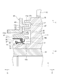
- FIG. 2 is a partial cross-sectional view taken along a line along an axis, for illustrating a schematic configuration of a sealing structure in a front cover of an engine as a resin cover according to the embodiment of the present invention.
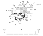
- FIG. 2 is a partially enlarged sectional view of the sealing structure shown in FIG. 1.
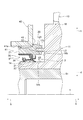
- FIG. 2 is a cross-sectional view schematically showing a structure of a single unit before being welded to a front cover of the sealing device shown in FIG.
- FIG. 4 is a partially enlarged cross-sectional view showing, in an enlarged manner, the vicinity of a joint portion of a support ring shown in FIG. It is sectional drawing which shows the modification of the labyrinth seal in the sealing structure in the engine front cover which concerns on embodiment of this invention.
- FIG. 1 is a partial cross-sectional view taken along a line along an axis, for illustrating a schematic configuration of a sealing structure in a front cover of an engine as a resin cover according to the embodiment of the present invention
- FIG. 10 is a cross-sectional view showing another modification of the labyrinth seal in the sealing structure of the front cover of the engine according to the embodiment of the present invention. It is sectional drawing which shows the modification of the sealing device in the sealing structure in the front cover of the engine which concerns on embodiment of this invention.
- FIG. 10 is a cross-sectional view showing another modification of the sealing device in the sealing structure of the front cover of the engine according to the embodiment of the present invention.
- FIG. 7 is a cross-sectional view showing a modification of a joint portion of a support ring in a sealing structure of a front cover of an engine according to an embodiment of the present invention.
- FIG. 1 is a cross-sectional view taken along an axis for illustrating a schematic configuration of a sealing structure (hereinafter, also simply referred to as a “sealing structure”) in an engine front cover as a resin cover according to an embodiment of the present invention.
- FIG. 2 is a partial sectional view, and FIG. 2 is a partially enlarged sectional view of the sealing structure shown in FIG.
- the direction of arrow a in the direction of the axis x is defined as the outside
- the direction of the arrow b in the direction of the axis x is defined as the inside.
- the outside is a direction away from the inside of the front cover
- the inside is a direction approaching the inside of the front cover.
- a direction perpendicular to the axis x hereinafter, also referred to as “radial direction”
- the direction away from the axis x is defined as the outer peripheral side
- the direction approaching the axis x is defined as the inner circumferential side.
- the sealing structure 1 in the front cover of the engine includes a resin engine front provided with a through hole 41 through which a shaft (a boss 14 of the torsion damper 10 described later) is inserted.
- a cover 40 and a sealing device 2 for sealing between the through hole 41 of the front cover 40 and the shaft portion are provided.
- the sealing device 2 includes an annular support ring 20 made of resin around the axis x, and an elastic body portion 30 formed of an annular elastic body around the axis x attached to the support ring 20.
- the elastic body portion 30 has an annular seal lip 31 with which the shaft portion slidably contacts the shaft portion, and the support ring 20 is joined to the front cover 40.
- the sealing structure 1 in the engine front cover includes a resin front cover, an torsion damper, and a torsion damper as a shaft portion of an engine used for a vehicle or a general-purpose machine.
- the present invention is applied to a sealing device for sealing an annular space between a boss portion and a through hole of a front cover.
- the damper pulley 10 as the torsional damper 10 is fixed to one end of a crankshaft 51 of the engine by a bolt 52.
- the damper pulley 10 includes a hub 11, a pulley 12 as a mass body, and a damper elastic body 13 disposed between the hub 11 and the pulley 12.
- the hub 11 is an annular member centered on the axis x, and has a boss 14 as an inner peripheral shaft, a rim 15 on the outer peripheral, and a substantially disk connecting the boss 14 and the rim 15. And a circular disk portion 16.
- the hub 11 is manufactured, for example, from a metal material by casting or the like.
- the boss portion 14 is an annular portion centered on the axis x where the through hole 14a is formed, and the disk portion 16 extends in the outer peripheral direction from the outer peripheral surface of the outer portion.
- the boss portion 14 has an outer peripheral surface 14b which is an outer peripheral surface of a cylindrical inner portion, and the outer peripheral surface 14b is a smooth surface.
- the rim portion 15 is an annular portion, more specifically, a cylindrical portion centered on the axis x, and is a portion located concentrically with the boss portion 14 and located on the outer peripheral side of the boss portion 14.
- a disk portion 16 extends in an inner circumferential direction from an inner circumferential surface 15a which is an inner circumferential surface of the rim portion 15.
- a damper elastic body 13 is crimped to an outer peripheral surface 15b which is an outer peripheral surface of the rim portion 15.
- the disk 16 extends between the boss 14 and the rim 15 and connects the boss 14 and the rim 15.
- the disk portion 16 may extend in a direction perpendicular to the axis x, or may extend in a direction inclined with respect to the axis x. Further, the disk portion 16 may have a curved cross section along the axis x (hereinafter, also simply referred to as a “cross section”) or may have a shape extending straight. Further, as shown in FIGS. 1 and 2, at least one window portion 16 a which is a through-hole penetrating the disk portion 16 between the inside and the outside is formed in the disk portion 16.
- four windows 16a are formed concentrically with respect to the axis x at equal angular intervals in the circumferential direction.
- the weight of the hub 11 and thus the damper pulley 10 is reduced by the window 16a.
- the damper pulley 10 does not need to have the window 16a.
- the pulley 12 is an annular member centered on the axis x, and has a shape that covers the hub 11 on the outer peripheral side.
- the inner peripheral surface 12a which is the inner peripheral surface of the pulley 12
- has a shape corresponding to the outer peripheral surface 15b of the rim portion 15 of the hub 11, and as shown in FIG. Are located such that the inner peripheral surface 12a thereof is opposed to the outer peripheral surface 15b of the rim portion 15 at an interval in the radial direction.
- a plurality of annular v-grooves 12c are formed on an outer peripheral surface 12b which is an outer peripheral surface of the pulley 12, so that a timing belt (not shown) can be wound.
- the damper elastic body 13 is provided between the pulley 12 and the rim 15 of the hub 11.
- the damper elastic body 13 is a damper rubber, and is formed by cross-linking a rubber-like elastic material having excellent heat resistance, cold resistance, and fatigue strength.
- the damper elastic body 13 is press-fitted between the pulley 12 and the rim portion 15 of the hub 11, and is fitted and fixed to the inner peripheral surface 12a of the pulley 12 and the outer peripheral surface 15b of the rim portion 15.
- the pulley 12 and the damper elastic body 13 form a damper portion, and the natural frequency of the damper portion in the torsional direction is a predetermined frequency range in which the torsion angle of the crankshaft 51 is maximized. Tuning is performed so as to match the natural frequency of the shaft 51 in the torsional direction. That is, the circumferential inertial mass of the pulley 12 and the torsional shear spring constant of the damper elastic body 13 are adjusted so that the natural frequency of the damper section in the torsional direction matches the natural frequency of the crankshaft 51 in the torsional direction. Have been.
- the damper pulley 10 has at least one torsion damper protrusion, which is an annular portion protruding in the direction of the axis x and forming a front cover 40 and a labyrinth seal L1 described later.
- the damper pulley 10 has two torsion damper protrusions (the outer protrusion 17a and the inner protrusion 17b).
- the outer peripheral side protruding portion 17a and the inner peripheral side protruding portion 17b are provided on an inner side surface 16b which is a disk-shaped surface facing inward on the inner peripheral side with respect to the window portion 16a of the disk portion 16 of the hub 11.
- annular portion protruding inward in the direction of the axis x from the inner side surface 16b and centered or substantially centered on the axis x.
- the outer peripheral side protruding portion 17a is provided on the outer peripheral side of the inner peripheral side protruding portion 17b, and a radial interval is constant or substantially constant between the outer peripheral side protruding portion 17a and the inner peripheral side protruding portion 17b.
- Hub groove 11b which is an annular groove centered or substantially centered on the axis x.
- the damper pulley 10 is attached to one end of the crankshaft 51 in the engine. Specifically, as shown in FIG. 1, one end of the crankshaft 51 is inserted into the through hole 14 a of the boss portion 14 of the hub 11, a bolt 52 is screwed into the crankshaft 51 from the outside, and the damper pulley 10 is It is fixed to the shaft 51.
- the damper pulley 10 When mounted on the crankshaft 51, the damper pulley 10 is configured such that an inner portion having the outer peripheral surface 14 b of the boss portion 14 is inserted into the through hole 41 of the front cover 40, An annular space (gap g1) is formed between the surface 14b and the through hole 41 of the front cover 40.
- the sealing device 2 has the support ring 20 made of resin and the elastic body portion 30 formed of an elastic body attached to the support ring 20. As shown in FIGS. 1 and 2, in the sealing structure 1, the sealing device 2 is joined to the front cover 40 at the support ring 20 by welding.
- FIG. 3 is a cross-sectional view of a cross-section along the axis x of the sealing device 2 schematically showing the configuration of the sealing device 2 itself before being welded to the front cover 40.
- the support ring 20 is an annular resin member centered or substantially centered on the axis x, and is an entrance portion which is an annular portion that enters the through hole 41 of the front cover 40. 21, a joining portion 22 which is an annular portion joined to the front cover 40 by welding, and an outer portion 23 which is an annular portion protruding outside the through hole 41 of the front cover 40.
- the support ring 20 is formed integrally from a resin material, and the entry portion 21, the joining portion 22, and the outer portion 23 are the respective portions of the support ring 20 formed integrally.
- the approach portion 21 extends along the axis x, and has an outer peripheral surface 21 a facing the outer peripheral side and an inner peripheral surface 21 b facing the inner peripheral side.
- the entry portion 21 is in the through hole 41 of the front cover 40, and the outer peripheral surface 21 a is used when the support ring 20 is attached to the front cover 40, for example.
- the shape is such that the entry portion 21 is guided into the through hole 41.
- the outer peripheral surface 21 a of the entry portion 21 is a tapered surface whose diameter decreases from the outside (the direction of the arrow a) to the inside (the direction of the arrow b) in the axis x direction.
- the diameter of the outer end (end 21 c) of the outer peripheral surface 21 a is the same or substantially the same as the diameter of the inner peripheral surface 41 a of the through hole 41 of the front cover 40. Thereby, the axial alignment between the through hole 41 of the front cover 40 and the sealing device 2 is facilitated.
- the joint portion 22 has an annular protrusion 22 a that is convex in the axis x direction.
- the support ring 20 is joined to the front cover 40 via a melted protrusion 22 a, and the protrusion 22 a of the joint portion 22 is a portion to be welded. is there.
- the joint portion 22 is provided with an annular concave portion 22b that is concave in the direction of the axis x on at least one of the inner peripheral side and the outer peripheral side of the protrusion 22a.
- one recess 22b is provided on the outer peripheral side of the protrusion 22a.
- the concave portion 22b forms a space into which the melted projection 22a flows when the support ring 20 is welded.
- FIG. 4 is a partially enlarged sectional view showing the vicinity of the joining portion 22 of the support ring 20 in an enlarged manner.
- the joining portion 22 has a joining surface 22c that is a surface facing inward in the direction of the annular axis x around the axis x.
- the concave portion 22b is concave outward from the joint surface 22c.
- the joining surface 22c is, for example, a plane orthogonal or substantially orthogonal to the axis x.
- the joint portion 22 may have a plurality of protrusions 22a arranged in the radial direction.
- the outer portion 23 of the support ring 20 is a portion that is connected to the entrance portion 21 on the outside, and is a portion where the joint portion 22 is formed. That is, the outer portion 23 protrudes to the outer peripheral side of the entrance portion 21.
- a welding jig guide portion 23a which is an annular concave portion concaved from the outside to the inside, is formed in the outer portion 23.
- the welding jig guide portion 23a is a portion to which a welding jig fits when the support ring 20 is welded to the front cover 40, as described later.
- the elastic body portion 30 is attached to the support ring 20, and is formed integrally with the support ring 20 so as to cover the inner peripheral side of the support ring 20 in the present embodiment.
- the elastic body portion 30 is attached to an inner peripheral surface 21 b of the entrance portion 21 of the support ring 20 and an annular convex portion 23 b protruding to the inner peripheral side of the outer portion 23.
- the elastic body portion 30 has the seal lip 31, and is provided outside the seal lip 31 (in the direction of the arrow a) and extends in the shape of an annular dust lip 32 extending toward the axis x. have. Further, the elastic body portion 30 has an annular lip waist portion 33.
- the seal lip 31 is formed such that the outer peripheral surface 14b slidably contacts the outer peripheral surface 14b of the boss portion 14 of the damper pulley 10 in the sealing structure 1.
- the dust lip 32 is provided outside the seal lip 31, and is formed such that the outer peripheral surface 14 b slidably contacts the outer peripheral surface 14 b of the boss 14 of the damper pulley 10.
- the lip waist portion 33 is a portion of the elastic body portion 30 that supports the seal lip 31 and the dust lip 32.
- the seal lip 31 is a portion that extends inward from the lip waist portion 33 and is an annular portion centered or substantially centered on the axis x. It is formed to face the part 21.
- the seal lip 31 has a wedge-shaped annular lip tip portion 34 whose cross-sectional shape is convex toward the inner peripheral side at an inner end portion.
- an annular concave portion 35 is formed at a position opposite to the lip tip portion 34, and a garter spring 36 is fitted into the concave portion 35.
- the garter spring 36 pushes the lip tip 34 in the direction toward the axis x so that the lip tip 34 follows the displacement of the boss 14 of the damper pulley 10 by a predetermined size relative to the boss 14. Gives the stress of being.
- the lip tip portion 34 comes into contact with the outer peripheral surface 14b of the boss portion 14 as described later to achieve sealing between the sealing device 2 and the boss portion 14.
- the dust strip 32 extends outward from the lip waist 33 toward the axis x, and specifically extends outward and inward from the lip waist 33 as shown in FIG.
- the dust lip 32 prevents foreign matters such as muddy water, sand, and dust from entering the lip tip portion 34 from the outside.
- the dust lip 32 may come close to the boss portion 14 of the damper pulley 10 without contacting the boss portion 14.
- the elastic portion 30 is integrally formed from an elastic material, and the seal lip 31, the dust lip 32, the lip waist portion 33, and other portions are the respective portions of the elastic portion 30 integrally formed from the elastic material. It is.
- the resin material of the support ring 20 is a resin that can be welded, for example, a thermoplastic resin, as described later.
- the resin material of the support ring 20 is a resin material that does not melt depending on the ambient temperature in the use state of the sealed structure 1, that is, the ambient temperature in the use state of the engine.
- the resin material of the support ring 20 is, for example, a hard thermoplastic synthetic resin material such as polyamide, polyester, polypropylene, and ABS resin.
- the resin material of the support ring 20 may be the same as the resin material of the front cover 40.
- examples of the elastic body of the elastic body section 30 include various rubber materials.
- the support ring 20 is manufactured by, for example, injection molding, and the elastic body portion 30 is formed by cross-linking (vulcanization) using a mold. At the time of this cross-linking molding, the support ring 20 is disposed in a molding die, the elastic body portion 30 is adhered to the support ring 20 by cross-linking adhesion, and the elastic body portion 30 is formed integrally with the support ring 20. You.
- the support ring 20 of the sealing device 2 has the entry portion 21 and the outer portion 23, is long in the axis x direction, and can cover the elastic body portion 30 on the inner peripheral side of the support ring 20. .
- the support ring 20 protects the elastic body portion 30 from the outside at the time of transporting the sealing device 2 in which the plurality of sealing devices 2 are stacked and transported in the direction of the axis x or at the time of assembling the sealing device 2.
- the front cover 40 is formed of a resin material as described above, and examples of the resin material include synthetic resins such as polyamide, polyester, polypropylene, and ABS resin. As shown in FIGS. 1 and 2, the front cover 40 has a through hole 41 through which the boss 14 of the crankshaft 51 and the damper pulley 10 is inserted. An annular gap g1 is formed between the inner peripheral surface 41a of the through hole 41 and the outer peripheral surface 14b of the boss portion 14, and the gap g1 is sealed by the sealing device 2 welded to the front cover 40. ing.
- the joining portion 22 of the support ring 20 is joined to the vicinity of the through hole 41 by welding on an outer surface 42 facing the outside of the front cover 40.
- the front cover 40 has a front cover projecting portion 43 which is an annular portion projecting from the outer surface 42 toward the disk portion 16 of the hub 11 of the damper pulley 10.
- the front cover projection 43 forms the above-described labyrinth seal L1 with the outer peripheral projection 17a and the inner peripheral projection 17b of the boss 14 of the damper pulley 10.
- the front cover protrusion 43 enters the hub groove 11b, which is an annular groove formed by the outer protrusion 17a and the inner protrusion 17b.
- the front cover protrusion 43 does not contact the hub groove 11b. For this reason, as shown in FIG. 2, an annular gap g2 having a U-shaped cross section is formed between the front cover protrusion 43 and the hub groove 11b, and between the front cover 40 and the damper pulley 10.
- a labyrinth seal L1 is formed. From the viewpoint of improving the sealing property of the labyrinth seal L1, the gap g2 between the front cover projection 43 and the hub groove 11b is preferably narrow.
- a method of joining the support ring 20 of the sealing device 2 to the front cover 40 will be described.
- a jig (not shown) is attached to the welding jig guide portion 23a of the sealing device 2 before joining shown in FIG. 3, the sealing device 2 is grasped by the jig, and the entry portion 21 of the support ring 20 is inserted into the through hole 41 of the front cover 40. It is inserted so that the projection 22 a of the joint portion 22 of the support ring 20 is in contact with the outer surface 42 of the front cover 40.
- the protrusion 22a of the joint portion 22 is vibrated while being pressed against the outer surface 42 of the front cover 40 to melt the protrusion 22a, and the support ring 20 is joined to the joint cover 22 by the melted protrusion 22a. Is welded to the outer surface 42.
- the means for vibrating the projection 22a for welding may be the above-described jig for gripping the sealing device 2 or may generate another vibration, and may be irradiated with ultrasonic waves or laser light. Or other means.
- an annular concave portion 22 b is formed in the joint portion 22, and when the support ring 20 is welded, a part of the molten protrusion that is not used for welding with the front cover 40. 22a flows into the recess 22b. For this reason, the joining state between the support ring 20 and the front cover 40 can be improved, and the formation of a welding beam can be suppressed or prevented.
- the concave portion 22b is located on the outer peripheral side of the projection 22a in the joint portion 22, but the concave portion 22b may be located on the inner peripheral side of the projection 22a.
- the recess 22b may be formed.
- the concave portion 22b may be formed on the outer peripheral side and the inner peripheral side of the protrusion 22a.
- a welding jig guide portion 23 a to which a jig is attached is formed on the support ring 20 of the sealing device 2, so that the efficiency of the operation of attaching the sealing device 2 to the front cover 40 can be improved.
- the resin support ring 20 is joined to the resin front cover 40 by welding. And, by this joining, the space between the sealing device 2 and the front cover 40 is sealed. Therefore, the difference in the coefficient of thermal expansion between the sealed portions of the support ring 20 and the front cover 40 can be reduced, and the joining state between the support ring 20 and the front cover 40 can be stabilized. The sealed state between the sealing device 2 and the front cover 40 can be stably maintained.
- the resin material of the support ring 20 and the resin material of the front cover 40 have a small difference in coefficient of thermal expansion.
- the relative position between the support ring 20 and the boss portion 14 of the damper pulley 10 may change due to a difference in thermal expansion coefficient. Or the gap between the dust lip 32 and the outer peripheral surface 14b of the boss portion 14 may be widened, so that foreign matter may easily enter the seal lip 31 side.
- the sealing structure 1 has the labyrinth seal L1 on the upstream side of the dust lip 32 in the foreign matter entry path, and the labyrinth seal L1 blocks entry of the foreign matter. For this reason, as described above, even if the dust lip 32 becomes in a state where foreign matter easily enters the seal lip 31 side due to thermal expansion, the labyrinth seal L1 can prevent foreign matter from entering, and the dust lip 32 can be prevented. Function can be supplemented. Further, the labyrinth seal L1 can further prevent foreign substances from entering.
- the sealing structure 1 in the engine front cover according to the embodiment of the present invention can maintain the sealing performance irrespective of the state of use.
- the present invention is not limited to the above-described embodiments of the present invention, but includes all aspects included in the concept of the present invention and the claims.
- the components may be appropriately selectively combined so as to achieve at least a part of the above-described problems and effects.
- the shape, material, arrangement, size, manufacturing method, and the like of each component in the above embodiment can be appropriately changed depending on the specific usage of the present invention.
- the form of the labyrinth seal upstream of the dust lip 32 in the foreign matter entry path in the present invention is not limited to the above-mentioned labyrinth seal L1, and may be another form.
- the labyrinth seal L1 is formed by inserting the front cover protrusion 43 into the hub groove 11b formed by the outer protrusion 17a and the inner protrusion 17b, but one protrusion and one protrusion are formed.
- a labyrinth seal may be formed by a gap formed by facing each other.
- the damper pulley 10 has only one of the outer peripheral side protruding portion 17a and the inner peripheral side protruding portion 17b, and the labyrinth seal L1 is connected to either the outer peripheral side protruding portion 17a or the inner peripheral side protruding portion 17b. It may be formed by the front cover protrusion 43.
- the front cover 40 has two front cover protrusions 43, and these two front cover protrusions 43 are the same as the outer peripheral side protrusion 17a and the inner peripheral side protrusion 17b.
- An annular groove may be formed in the groove, and the outer peripheral side projection 17a or the inner peripheral side projection 17b may enter the groove to form the labyrinth seal L1.
- the damper pulley 10 may have only one of the outer peripheral side protruding portion 17a and the inner peripheral side protruding portion 17b.
- the front cover 40 has a plurality of front cover protrusions 43
- the damper pulley 10 has a plurality of torsion damper protrusions (outer periphery protrusion 17a or inner periphery protrusion 17b).
- the labyrinth seal L1 may be formed by a gap between the plurality of protrusions.
- the supporting ring 20 may form a labyrinth seal with the damper pulley 10 instead of, or together with, the labyrinth seal L1 described above.
- a labyrinth seal L2 may be provided between the support ring 20 and the damper pulley 10.
- an annular projection 17c that enters the welding jig guide 23a of the outer portion 23 of the support ring 20, and between the projection 17c and the welding jig guide 23a.
- a labyrinth seal L2 may be formed between the support ring 20 and the damper pulley 10 by forming an annular gap g3 having a U-shaped cross section.
- the labyrinth seal L2 between the support ring 20 and the damper pulley 10 may have another form.
- the labyrinth seal L2 may be formed by forming an annular gap in which the protruding portion 17c faces the outer peripheral surface or the inner peripheral surface of the outer portion 23 of the support ring 20 from the outer peripheral side or the inner peripheral side.
- the damper pulley 10 may have the hub groove 11b instead of the protrusion 17c, and the support ring 20 may have an annular protrusion that enters the hub groove 11b and forms the labyrinth seal L2.
- the support ring 20 is joined to the front cover 40 by welding, but the support ring 20 may be joined to the front cover 40 by an adhesive.
- the support ring 20 does not have to have the protrusion 22a and the recess 22b in the joint portion 22, but has only the joint surface 22c.
- the joint 22 may have a recess 22b as a space for the adhesive to escape.
- the support ring in the sealing device of the present invention is not limited to the above-described support ring 20, and may have any other shape as long as the elastic body portion 30 is attached and can be joined to the front cover 40.
- the sealing device may be a modified example as shown in FIGS.
- the sealing device 3 according to the first modification has a support ring 24 different from the support ring 20 of the sealing device 2, and the support ring 24 has an entry portion 21. Absent.
- the sealing device 4 according to the second modified example has a supporting ring 25 different from the supporting ring 20 of the sealing device 2, and the supporting ring 25 is No part 23 is provided.
- the portion where the support ring 20 is welded to the front cover 40 is not limited to the above-described portion (joining portion 22).
- the joint portion 22 may be located at another support ring 20, and the support ring 20 may have a plurality of joint portions 22.
- the support ring 20 may have a joining portion 22 also on the inner side surface 21 d of the entry portion 21. In this case, a portion where the joining portion 22 of the entry portion 21 is welded to the front cover 40 is provided.
- the resin cover of the present invention is not limited to the engine front cover and may be made of another resin. Cover.
- the present invention can be applied to a sealing structure between a shaft portion that moves, such as a rotary motion and a reciprocating motion, and a resin cover, and the resin cover of the present invention
- the cover may be a resin cover for a machine, a resin cover for a differential mechanism of an automobile or the like, a resin cover for a steering mechanism, a resin cover for a motor, a resin cover for a reduction gear, or the like.
- a shaft portion that moves such as a rotary motion and a reciprocating motion, and a resin cover having a space through which the shaft portion is inserted The present invention can be applied.
- SYMBOLS 1 Sealing structure in engine front cover, 2, 3, 4 ... Sealing device, 10 ... Torsion damper (damper pulley), 11 ... Hub, 11b ... Hub groove, 12 ... Pulley, 12a ... Inner peripheral surface, 12b ... Outer periphery Surface, 12c: v-groove, 13: damper elastic body, 14: boss, 14a: through hole, 14b: outer peripheral surface, 15: rim, 15a: inner peripheral surface, 15b: outer peripheral surface, 16: disk portion, 16a ... Window, 16b ... Inner side, 17a ... Outer side protruding part, 17b ... Inner side protruding part, 17c ...
Landscapes
- Engineering & Computer Science (AREA)
- Mechanical Engineering (AREA)
- General Engineering & Computer Science (AREA)
- Physics & Mathematics (AREA)
- Thermal Sciences (AREA)
- Sealing Using Fluids, Sealing Without Contact, And Removal Of Oil (AREA)
- Sealing Devices (AREA)
- Cylinder Crankcases Of Internal Combustion Engines (AREA)
- Sealing With Elastic Sealing Lips (AREA)
Abstract
L'invention concerne une structure d'étanchéité destinée à un capot en résine, conçue de telle sorte que les propriétés d'étanchéité peuvent être maintenues indépendamment de l'état d'utilisation. Une structure d'étanchéité (1) destinée à un capot avant destiné à un moteur est pourvue : d'un capot avant en résine (40) destiné à un moteur, qui est pourvu d'un trou traversant (41) dans lequel un bossage (14) d'un amortisseur de torsion (10) est inséré ; et d'un dispositif d'étanchéité (2) destiné à assurer l'étanchéité entre le trou traversant (41) dans le capot avant (40) et une section d'arbre. Le dispositif d'étanchéité (2) est pourvu d'une bague de support (20) annulaire en résine et d'une section de corps élastique (30) qui est formée d'un corps élastique annulaire et qui est montée sur la bague de support (20). La section de corps élastique (30) présente une lèvre d'étanchéité annulaire (31) qui vient en contact coulissant avec la section d'arbre. La bague de support (20) est jointe au capot avant (40).
Priority Applications (4)
| Application Number | Priority Date | Filing Date | Title |
|---|---|---|---|
| US17/059,167 US11668397B2 (en) | 2018-08-28 | 2019-08-09 | Sealing structure for cover made of resin |
| JP2020539313A JP7062072B2 (ja) | 2018-08-28 | 2019-08-09 | 樹脂製カバーにおける密封構造 |
| CN201980035379.0A CN112166268B (zh) | 2018-08-28 | 2019-08-09 | 树脂制盖中的密封结构 |
| EP19856169.8A EP3845780A4 (fr) | 2018-08-28 | 2019-08-09 | Structure d'étanchéité pour capot en résine |
Applications Claiming Priority (2)
| Application Number | Priority Date | Filing Date | Title |
|---|---|---|---|
| JP2018159351 | 2018-08-28 | ||
| JP2018-159351 | 2018-08-28 |
Publications (1)
| Publication Number | Publication Date |
|---|---|
| WO2020045062A1 true WO2020045062A1 (fr) | 2020-03-05 |
Family
ID=69644913
Family Applications (1)
| Application Number | Title | Priority Date | Filing Date |
|---|---|---|---|
| PCT/JP2019/031669 WO2020045062A1 (fr) | 2018-08-28 | 2019-08-09 | Structure d'étanchéité pour capot en résine |
Country Status (5)
| Country | Link |
|---|---|
| US (1) | US11668397B2 (fr) |
| EP (1) | EP3845780A4 (fr) |
| JP (1) | JP7062072B2 (fr) |
| CN (1) | CN112166268B (fr) |
| WO (1) | WO2020045062A1 (fr) |
Cited By (3)
| Publication number | Priority date | Publication date | Assignee | Title |
|---|---|---|---|---|
| JP2021092166A (ja) * | 2019-12-09 | 2021-06-17 | 日産自動車株式会社 | 内燃機関のチェーンケース |
| JP2022079920A (ja) * | 2020-11-17 | 2022-05-27 | トヨタ紡織株式会社 | 内燃機関のカバー |
| US20230184127A1 (en) * | 2021-12-14 | 2023-06-15 | Regi U.S., Inc. | Rotary vane device with longitudinally extending seals |
Citations (7)
| Publication number | Priority date | Publication date | Assignee | Title |
|---|---|---|---|---|
| JPH0571542U (ja) * | 1992-03-09 | 1993-09-28 | エヌオーケー株式会社 | 密封装置 |
| JPH0755015A (ja) | 1993-05-05 | 1995-03-03 | Freudenberg Nok General Partnership | ハウジングカバーおよびシール組立体 |
| JPH11216776A (ja) * | 1998-02-02 | 1999-08-10 | Nissan Motor Co Ltd | 振動溶着リブ構造および振動溶着方法 |
| JP2006242000A (ja) * | 2005-02-28 | 2006-09-14 | Toyota Motor Corp | バルブケース及びシリンダヘッドカバーの形成方法 |
| JP2009209688A (ja) * | 2008-02-29 | 2009-09-17 | Daikyonishikawa Corp | オイルセパレータの構造 |
| JP2011241891A (ja) * | 2010-05-18 | 2011-12-01 | Nok Corp | ダンパ |
| JP2016121763A (ja) * | 2014-12-25 | 2016-07-07 | Nok株式会社 | トーショナルダンパとオイルシールとのラビリンス構造 |
Family Cites Families (17)
| Publication number | Priority date | Publication date | Assignee | Title |
|---|---|---|---|---|
| JPH05177711A (ja) | 1991-12-27 | 1993-07-20 | Tsuchiya Mfg Co Ltd | 合成樹脂部材の溶着方法 |
| JPH06285994A (ja) * | 1993-03-31 | 1994-10-11 | Tsuchiya Mfg Co Ltd | 合成樹脂部材の溶着方法 |
| JP4639619B2 (ja) * | 2004-03-23 | 2011-02-23 | Nok株式会社 | 往復動軸用密封装置 |
| JP2008057756A (ja) * | 2006-09-04 | 2008-03-13 | Kayaba Ind Co Ltd | 往復動用オイルシール |
| JP5041137B2 (ja) | 2007-01-29 | 2012-10-03 | Nok株式会社 | 密封装置 |
| JP2008309263A (ja) * | 2007-06-15 | 2008-12-25 | Nok Corp | 密封装置 |
| JP2009103142A (ja) | 2007-10-19 | 2009-05-14 | Toyota Motor Corp | シール装置 |
| JP5585754B2 (ja) * | 2009-03-31 | 2014-09-10 | Nok株式会社 | シール部品の製造方法及び金型 |
| WO2014119204A1 (fr) * | 2013-01-29 | 2014-08-07 | イーグル工業株式会社 | Dispositif d'étanchéité |
| JP6241188B2 (ja) * | 2013-10-16 | 2017-12-06 | 日本精工株式会社 | エンコーダ付組み合わせシールリング及びエンコーダ付転がり軸受ユニット |
| EP3171057A4 (fr) * | 2014-07-17 | 2018-04-11 | Eagle Industry Co., Ltd. | Dispositif d'étanchéité |
| WO2016088872A1 (fr) * | 2014-12-04 | 2016-06-09 | Nok株式会社 | Structure d'étanchéité utilisant un amortisseur à torsion et un joint d'étanchéité à huile |
| WO2016111129A1 (fr) * | 2015-01-07 | 2016-07-14 | Nok株式会社 | Structure d'étanchéité utilisant un amortisseur de torsion et un joint d'huile |
| JP6498472B2 (ja) | 2015-02-24 | 2019-04-10 | 株式会社荒井製作所 | 密封装置 |
| JP6103002B2 (ja) * | 2015-08-20 | 2017-03-29 | 日本精工株式会社 | エンコーダ及び組み合わせシールリング付ハブユニット |
| CN108027067B (zh) | 2015-09-25 | 2020-07-28 | Nok株式会社 | 差速机构用密封装置 |
| KR102114195B1 (ko) | 2016-05-18 | 2020-05-22 | 엔오케이 가부시키가이샤 | 환형상의 포켓과 밀봉 장치를 이용한 밀봉 구조 |
-
2019
- 2019-08-09 US US17/059,167 patent/US11668397B2/en active Active
- 2019-08-09 WO PCT/JP2019/031669 patent/WO2020045062A1/fr unknown
- 2019-08-09 CN CN201980035379.0A patent/CN112166268B/zh active Active
- 2019-08-09 JP JP2020539313A patent/JP7062072B2/ja active Active
- 2019-08-09 EP EP19856169.8A patent/EP3845780A4/fr active Pending
Patent Citations (7)
| Publication number | Priority date | Publication date | Assignee | Title |
|---|---|---|---|---|
| JPH0571542U (ja) * | 1992-03-09 | 1993-09-28 | エヌオーケー株式会社 | 密封装置 |
| JPH0755015A (ja) | 1993-05-05 | 1995-03-03 | Freudenberg Nok General Partnership | ハウジングカバーおよびシール組立体 |
| JPH11216776A (ja) * | 1998-02-02 | 1999-08-10 | Nissan Motor Co Ltd | 振動溶着リブ構造および振動溶着方法 |
| JP2006242000A (ja) * | 2005-02-28 | 2006-09-14 | Toyota Motor Corp | バルブケース及びシリンダヘッドカバーの形成方法 |
| JP2009209688A (ja) * | 2008-02-29 | 2009-09-17 | Daikyonishikawa Corp | オイルセパレータの構造 |
| JP2011241891A (ja) * | 2010-05-18 | 2011-12-01 | Nok Corp | ダンパ |
| JP2016121763A (ja) * | 2014-12-25 | 2016-07-07 | Nok株式会社 | トーショナルダンパとオイルシールとのラビリンス構造 |
Non-Patent Citations (1)
| Title |
|---|
| See also references of EP3845780A4 |
Cited By (6)
| Publication number | Priority date | Publication date | Assignee | Title |
|---|---|---|---|---|
| JP2021092166A (ja) * | 2019-12-09 | 2021-06-17 | 日産自動車株式会社 | 内燃機関のチェーンケース |
| JP7448346B2 (ja) | 2019-12-09 | 2024-03-12 | 日産自動車株式会社 | 内燃機関のチェーンケース |
| JP2022079920A (ja) * | 2020-11-17 | 2022-05-27 | トヨタ紡織株式会社 | 内燃機関のカバー |
| JP7480682B2 (ja) | 2020-11-17 | 2024-05-10 | トヨタ紡織株式会社 | 内燃機関のカバー |
| US20230184127A1 (en) * | 2021-12-14 | 2023-06-15 | Regi U.S., Inc. | Rotary vane device with longitudinally extending seals |
| US11873816B2 (en) * | 2021-12-14 | 2024-01-16 | Regi U.S., Inc. | Rotary vane device with longitudinally extending seals |
Also Published As
| Publication number | Publication date |
|---|---|
| EP3845780A4 (fr) | 2022-05-11 |
| US20210215251A1 (en) | 2021-07-15 |
| JPWO2020045062A1 (ja) | 2021-03-11 |
| CN112166268A (zh) | 2021-01-01 |
| JP7062072B2 (ja) | 2022-05-02 |
| US11668397B2 (en) | 2023-06-06 |
| EP3845780A1 (fr) | 2021-07-07 |
| CN112166268B (zh) | 2023-01-31 |
Similar Documents
| Publication | Publication Date | Title |
|---|---|---|
| WO2020045062A1 (fr) | Structure d'étanchéité pour capot en résine | |
| JP6642453B2 (ja) | トーショナルダンパとオイルシールとを用いた密封構造 | |
| JP5791875B2 (ja) | ダンパ | |
| JP2007107637A (ja) | トルク変動吸収ダンパ | |
| US8047328B1 (en) | Plastic muffler and method for making same | |
| US20070249442A1 (en) | Belt pulley with integrated torsional oscillation damper and process for producing same | |
| JP6650457B2 (ja) | 1つ以上のエラストマ部材を収容したカートリッジを備えたドライブシステムのための装置 | |
| KR101211051B1 (ko) | 트리거 플레이트가 부착된 댐퍼 | |
| JP6521480B2 (ja) | トーショナルダンパとオイルシールとによる密封構造 | |
| JP2574648B2 (ja) | ねじり振動ダンパー | |
| JP2017214994A (ja) | 環状のポケットと密封装置とを用いた密封構造、および、トーショナルダンパとオイルシールとを用いた密封構造 | |
| JP2007071263A (ja) | トルク変動吸収ダンパ | |
| JP2009019691A (ja) | クランクプーリ | |
| JP6890718B2 (ja) | 気流発生構造体および密封構造 | |
| JP5472607B2 (ja) | トルク変動吸収ダンパ | |
| JP2006194265A (ja) | トルク変動吸収ダンパ | |
| JP6474030B2 (ja) | トーショナルダンパとオイルシールとのラビリンス構造 | |
| JP2008057553A (ja) | ダンパ付プーリ | |
| JP7178930B2 (ja) | トーショナルダンパー | |
| JP2007170476A (ja) | 駆動軸用ダンパ | |
| JP7281428B2 (ja) | プーリ構造体 | |
| JP7285683B2 (ja) | 密封装置、及び、密封構造 | |
| JP2004116640A (ja) | トルク変動吸収ダンパ | |
| JP6280345B2 (ja) | 回転変動吸収ダンパ | |
| JPH036381B2 (fr) |
Legal Events
| Date | Code | Title | Description |
|---|---|---|---|
| 121 | Ep: the epo has been informed by wipo that ep was designated in this application |
Ref document number: 19856169 Country of ref document: EP Kind code of ref document: A1 |
|
| ENP | Entry into the national phase |
Ref document number: 2020539313 Country of ref document: JP Kind code of ref document: A |
|
| NENP | Non-entry into the national phase |
Ref country code: DE |
|
| ENP | Entry into the national phase |
Ref document number: 2019856169 Country of ref document: EP Effective date: 20210329 |