EP3845780A1 - Structure d'étanchéité pour capot en résine - Google Patents
Structure d'étanchéité pour capot en résine Download PDFInfo
- Publication number
- EP3845780A1 EP3845780A1 EP19856169.8A EP19856169A EP3845780A1 EP 3845780 A1 EP3845780 A1 EP 3845780A1 EP 19856169 A EP19856169 A EP 19856169A EP 3845780 A1 EP3845780 A1 EP 3845780A1
- Authority
- EP
- European Patent Office
- Prior art keywords
- support ring
- resin
- annular
- front cover
- cover made
- Prior art date
- Legal status (The legal status is an assumption and is not a legal conclusion. Google has not performed a legal analysis and makes no representation as to the accuracy of the status listed.)
- Pending
Links
Images


Classifications
-
- F—MECHANICAL ENGINEERING; LIGHTING; HEATING; WEAPONS; BLASTING
- F16—ENGINEERING ELEMENTS AND UNITS; GENERAL MEASURES FOR PRODUCING AND MAINTAINING EFFECTIVE FUNCTIONING OF MACHINES OR INSTALLATIONS; THERMAL INSULATION IN GENERAL
- F16J—PISTONS; CYLINDERS; SEALINGS
- F16J15/00—Sealings
- F16J15/16—Sealings between relatively-moving surfaces
- F16J15/32—Sealings between relatively-moving surfaces with elastic sealings, e.g. O-rings
- F16J15/3204—Sealings between relatively-moving surfaces with elastic sealings, e.g. O-rings with at least one lip
-
- F—MECHANICAL ENGINEERING; LIGHTING; HEATING; WEAPONS; BLASTING
- F16—ENGINEERING ELEMENTS AND UNITS; GENERAL MEASURES FOR PRODUCING AND MAINTAINING EFFECTIVE FUNCTIONING OF MACHINES OR INSTALLATIONS; THERMAL INSULATION IN GENERAL
- F16J—PISTONS; CYLINDERS; SEALINGS
- F16J15/00—Sealings
- F16J15/16—Sealings between relatively-moving surfaces
- F16J15/32—Sealings between relatively-moving surfaces with elastic sealings, e.g. O-rings
- F16J15/3248—Sealings between relatively-moving surfaces with elastic sealings, e.g. O-rings provided with casings or supports
- F16J15/3252—Sealings between relatively-moving surfaces with elastic sealings, e.g. O-rings provided with casings or supports with rigid casings or supports
-
- B—PERFORMING OPERATIONS; TRANSPORTING
- B29—WORKING OF PLASTICS; WORKING OF SUBSTANCES IN A PLASTIC STATE IN GENERAL
- B29C—SHAPING OR JOINING OF PLASTICS; SHAPING OF MATERIAL IN A PLASTIC STATE, NOT OTHERWISE PROVIDED FOR; AFTER-TREATMENT OF THE SHAPED PRODUCTS, e.g. REPAIRING
- B29C65/00—Joining or sealing of preformed parts, e.g. welding of plastics materials; Apparatus therefor
- B29C65/02—Joining or sealing of preformed parts, e.g. welding of plastics materials; Apparatus therefor by heating, with or without pressure
- B29C65/06—Joining or sealing of preformed parts, e.g. welding of plastics materials; Apparatus therefor by heating, with or without pressure using friction, e.g. spin welding
-
- B—PERFORMING OPERATIONS; TRANSPORTING
- B29—WORKING OF PLASTICS; WORKING OF SUBSTANCES IN A PLASTIC STATE IN GENERAL
- B29C—SHAPING OR JOINING OF PLASTICS; SHAPING OF MATERIAL IN A PLASTIC STATE, NOT OTHERWISE PROVIDED FOR; AFTER-TREATMENT OF THE SHAPED PRODUCTS, e.g. REPAIRING
- B29C66/00—General aspects of processes or apparatus for joining preformed parts
- B29C66/01—General aspects dealing with the joint area or with the area to be joined
- B29C66/05—Particular design of joint configurations
- B29C66/10—Particular design of joint configurations particular design of the joint cross-sections
- B29C66/13—Single flanged joints; Fin-type joints; Single hem joints; Edge joints; Interpenetrating fingered joints; Other specific particular designs of joint cross-sections not provided for in groups B29C66/11 - B29C66/12
- B29C66/131—Single flanged joints, i.e. one of the parts to be joined being rigid and flanged in the joint area
-
- B—PERFORMING OPERATIONS; TRANSPORTING
- B29—WORKING OF PLASTICS; WORKING OF SUBSTANCES IN A PLASTIC STATE IN GENERAL
- B29C—SHAPING OR JOINING OF PLASTICS; SHAPING OF MATERIAL IN A PLASTIC STATE, NOT OTHERWISE PROVIDED FOR; AFTER-TREATMENT OF THE SHAPED PRODUCTS, e.g. REPAIRING
- B29C66/00—General aspects of processes or apparatus for joining preformed parts
- B29C66/01—General aspects dealing with the joint area or with the area to be joined
- B29C66/05—Particular design of joint configurations
- B29C66/302—Particular design of joint configurations the area to be joined comprising melt initiators
- B29C66/3022—Particular design of joint configurations the area to be joined comprising melt initiators said melt initiators being integral with at least one of the parts to be joined
- B29C66/30223—Particular design of joint configurations the area to be joined comprising melt initiators said melt initiators being integral with at least one of the parts to be joined said melt initiators being rib-like
-
- B—PERFORMING OPERATIONS; TRANSPORTING
- B29—WORKING OF PLASTICS; WORKING OF SUBSTANCES IN A PLASTIC STATE IN GENERAL
- B29C—SHAPING OR JOINING OF PLASTICS; SHAPING OF MATERIAL IN A PLASTIC STATE, NOT OTHERWISE PROVIDED FOR; AFTER-TREATMENT OF THE SHAPED PRODUCTS, e.g. REPAIRING
- B29C66/00—General aspects of processes or apparatus for joining preformed parts
- B29C66/01—General aspects dealing with the joint area or with the area to be joined
- B29C66/32—Measures for keeping the burr form under control; Avoiding burr formation; Shaping the burr
- B29C66/322—Providing cavities in the joined article to collect the burr
-
- B—PERFORMING OPERATIONS; TRANSPORTING
- B29—WORKING OF PLASTICS; WORKING OF SUBSTANCES IN A PLASTIC STATE IN GENERAL
- B29C—SHAPING OR JOINING OF PLASTICS; SHAPING OF MATERIAL IN A PLASTIC STATE, NOT OTHERWISE PROVIDED FOR; AFTER-TREATMENT OF THE SHAPED PRODUCTS, e.g. REPAIRING
- B29C66/00—General aspects of processes or apparatus for joining preformed parts
- B29C66/50—General aspects of joining tubular articles; General aspects of joining long products, i.e. bars or profiled elements; General aspects of joining single elements to tubular articles, hollow articles or bars; General aspects of joining several hollow-preforms to form hollow or tubular articles
- B29C66/51—Joining tubular articles, profiled elements or bars; Joining single elements to tubular articles, hollow articles or bars; Joining several hollow-preforms to form hollow or tubular articles
- B29C66/53—Joining single elements to tubular articles, hollow articles or bars
- B29C66/532—Joining single elements to the wall of tubular articles, hollow articles or bars
- B29C66/5324—Joining single elements to the wall of tubular articles, hollow articles or bars said single elements being substantially annular, i.e. of finite length
- B29C66/53245—Joining single elements to the wall of tubular articles, hollow articles or bars said single elements being substantially annular, i.e. of finite length said articles being hollow
-
- B—PERFORMING OPERATIONS; TRANSPORTING
- B29—WORKING OF PLASTICS; WORKING OF SUBSTANCES IN A PLASTIC STATE IN GENERAL
- B29C—SHAPING OR JOINING OF PLASTICS; SHAPING OF MATERIAL IN A PLASTIC STATE, NOT OTHERWISE PROVIDED FOR; AFTER-TREATMENT OF THE SHAPED PRODUCTS, e.g. REPAIRING
- B29C66/00—General aspects of processes or apparatus for joining preformed parts
- B29C66/50—General aspects of joining tubular articles; General aspects of joining long products, i.e. bars or profiled elements; General aspects of joining single elements to tubular articles, hollow articles or bars; General aspects of joining several hollow-preforms to form hollow or tubular articles
- B29C66/51—Joining tubular articles, profiled elements or bars; Joining single elements to tubular articles, hollow articles or bars; Joining several hollow-preforms to form hollow or tubular articles
- B29C66/53—Joining single elements to tubular articles, hollow articles or bars
- B29C66/534—Joining single elements to open ends of tubular or hollow articles or to the ends of bars
- B29C66/5344—Joining single elements to open ends of tubular or hollow articles or to the ends of bars said single elements being substantially annular, i.e. of finite length, e.g. joining flanges to tube ends
-
- B—PERFORMING OPERATIONS; TRANSPORTING
- B29—WORKING OF PLASTICS; WORKING OF SUBSTANCES IN A PLASTIC STATE IN GENERAL
- B29C—SHAPING OR JOINING OF PLASTICS; SHAPING OF MATERIAL IN A PLASTIC STATE, NOT OTHERWISE PROVIDED FOR; AFTER-TREATMENT OF THE SHAPED PRODUCTS, e.g. REPAIRING
- B29C66/00—General aspects of processes or apparatus for joining preformed parts
- B29C66/70—General aspects of processes or apparatus for joining preformed parts characterised by the composition, physical properties or the structure of the material of the parts to be joined; Joining with non-plastics material
- B29C66/73—General aspects of processes or apparatus for joining preformed parts characterised by the composition, physical properties or the structure of the material of the parts to be joined; Joining with non-plastics material characterised by the intensive physical properties of the material of the parts to be joined, by the optical properties of the material of the parts to be joined, by the extensive physical properties of the parts to be joined, by the state of the material of the parts to be joined or by the material of the parts to be joined being a thermoplastic or a thermoset
- B29C66/731—General aspects of processes or apparatus for joining preformed parts characterised by the composition, physical properties or the structure of the material of the parts to be joined; Joining with non-plastics material characterised by the intensive physical properties of the material of the parts to be joined, by the optical properties of the material of the parts to be joined, by the extensive physical properties of the parts to be joined, by the state of the material of the parts to be joined or by the material of the parts to be joined being a thermoplastic or a thermoset characterised by the intensive physical properties of the material of the parts to be joined
- B29C66/7311—Thermal properties
- B29C66/73111—Thermal expansion coefficient
- B29C66/73112—Thermal expansion coefficient of different thermal expansion coefficient, i.e. the thermal expansion coefficient of one of the parts to be joined being different from the thermal expansion coefficient of the other part
-
- F—MECHANICAL ENGINEERING; LIGHTING; HEATING; WEAPONS; BLASTING
- F16—ENGINEERING ELEMENTS AND UNITS; GENERAL MEASURES FOR PRODUCING AND MAINTAINING EFFECTIVE FUNCTIONING OF MACHINES OR INSTALLATIONS; THERMAL INSULATION IN GENERAL
- F16J—PISTONS; CYLINDERS; SEALINGS
- F16J15/00—Sealings
- F16J15/44—Free-space packings
- F16J15/447—Labyrinth packings
- F16J15/4476—Labyrinth packings with radial path
-
- B—PERFORMING OPERATIONS; TRANSPORTING
- B29—WORKING OF PLASTICS; WORKING OF SUBSTANCES IN A PLASTIC STATE IN GENERAL
- B29C—SHAPING OR JOINING OF PLASTICS; SHAPING OF MATERIAL IN A PLASTIC STATE, NOT OTHERWISE PROVIDED FOR; AFTER-TREATMENT OF THE SHAPED PRODUCTS, e.g. REPAIRING
- B29C65/00—Joining or sealing of preformed parts, e.g. welding of plastics materials; Apparatus therefor
- B29C65/02—Joining or sealing of preformed parts, e.g. welding of plastics materials; Apparatus therefor by heating, with or without pressure
- B29C65/08—Joining or sealing of preformed parts, e.g. welding of plastics materials; Apparatus therefor by heating, with or without pressure using ultrasonic vibrations
-
- B—PERFORMING OPERATIONS; TRANSPORTING
- B29—WORKING OF PLASTICS; WORKING OF SUBSTANCES IN A PLASTIC STATE IN GENERAL
- B29C—SHAPING OR JOINING OF PLASTICS; SHAPING OF MATERIAL IN A PLASTIC STATE, NOT OTHERWISE PROVIDED FOR; AFTER-TREATMENT OF THE SHAPED PRODUCTS, e.g. REPAIRING
- B29C65/00—Joining or sealing of preformed parts, e.g. welding of plastics materials; Apparatus therefor
- B29C65/02—Joining or sealing of preformed parts, e.g. welding of plastics materials; Apparatus therefor by heating, with or without pressure
- B29C65/14—Joining or sealing of preformed parts, e.g. welding of plastics materials; Apparatus therefor by heating, with or without pressure using wave energy, i.e. electromagnetic radiation, or particle radiation
- B29C65/16—Laser beams
-
- B—PERFORMING OPERATIONS; TRANSPORTING
- B29—WORKING OF PLASTICS; WORKING OF SUBSTANCES IN A PLASTIC STATE IN GENERAL
- B29C—SHAPING OR JOINING OF PLASTICS; SHAPING OF MATERIAL IN A PLASTIC STATE, NOT OTHERWISE PROVIDED FOR; AFTER-TREATMENT OF THE SHAPED PRODUCTS, e.g. REPAIRING
- B29C65/00—Joining or sealing of preformed parts, e.g. welding of plastics materials; Apparatus therefor
- B29C65/48—Joining or sealing of preformed parts, e.g. welding of plastics materials; Apparatus therefor using adhesives, i.e. using supplementary joining material; solvent bonding
-
- B—PERFORMING OPERATIONS; TRANSPORTING
- B29—WORKING OF PLASTICS; WORKING OF SUBSTANCES IN A PLASTIC STATE IN GENERAL
- B29L—INDEXING SCHEME ASSOCIATED WITH SUBCLASS B29C, RELATING TO PARTICULAR ARTICLES
- B29L2031/00—Other particular articles
- B29L2031/26—Sealing devices, e.g. packaging for pistons or pipe joints
-
- B—PERFORMING OPERATIONS; TRANSPORTING
- B29—WORKING OF PLASTICS; WORKING OF SUBSTANCES IN A PLASTIC STATE IN GENERAL
- B29L—INDEXING SCHEME ASSOCIATED WITH SUBCLASS B29C, RELATING TO PARTICULAR ARTICLES
- B29L2031/00—Other particular articles
- B29L2031/748—Machines or parts thereof not otherwise provided for
- B29L2031/749—Motors
-
- F—MECHANICAL ENGINEERING; LIGHTING; HEATING; WEAPONS; BLASTING
- F02—COMBUSTION ENGINES; HOT-GAS OR COMBUSTION-PRODUCT ENGINE PLANTS
- F02F—CYLINDERS, PISTONS OR CASINGS, FOR COMBUSTION ENGINES; ARRANGEMENTS OF SEALINGS IN COMBUSTION ENGINES
- F02F7/00—Casings, e.g. crankcases
- F02F7/0065—Shape of casings for other machine parts and purposes, e.g. utilisation purposes, safety
- F02F7/0073—Adaptations for fitting the engine, e.g. front-plates or bell-housings
- F02F2007/0078—Covers for belt transmissions
Definitions
- the present invention relates to a sealing structure for a cover made of resin, and particularly relates to a sealing structure with a sealing apparatus between a front cover made of resin of an engine or the like and a movable member.
- a through-hole is formed in a front cover of the engine that covers an accessory attached to a side surface of a crankcase or a timing chain, an end portion of a crankshaft protrudes to the outside through the through-hole, and a torsional damper is attached to the end portion.
- an annular space is formed between the through-hole and the end portion of the crankshaft or a boss part of the torsional damper, and an oil seal serving as a sealing apparatus is used to seal the space.
- the oil seal is press-fitted into the through-hole of the front cover and fastened to the front cover by a rubber material on an outer periphery side thereof which is compressed (For example, see Patent Literature 1).
- the conventional front cover of an engine is made of metal, such as an aluminum alloy, it is being contemplated to use resin to make the front cover of an engine in order to reduce the weight.
- Patent Literature 1 Japanese Patent Application Publication No. 7-55015
- a molded piece made of resin has a large dimensional tolerance, and the resin has a high coefficient of thermal expansion and a large creep deformation. Therefore, if a front cover made of resin is used for an engine, there is a concern that a gap would be formed between the oil seal press-fitted into the through-hole and the front cover. In particular, because of the difference in coefficient of thermal expansion between the rubber material forming the oil seal and the resin material forming the front cover, a gap may be formed between the inner circumferential surface of the through-hole of the front cover and the outer circumferential surface of the oil seal when the front cover is thermally expanded.
- the sealing structure for a cover made of resin such as a front cover made of resin for an engine, needs to be a structure that can maintain the sealing performance regardless of the usage state thereof, such as the ambient temperature.
- the present invention has been made in view of the problems described above, and it is an object of the present invention to provide a sealing structure for a cover made of resin that can maintain the sealing performance regardless of the usage state thereof.
- a sealing structure for a cover made of resin is characterized by including a cover made of resin in which a through-hole, into which a shaft part is to be inserted, is provided, and a sealing apparatus to seal between the through-hole of the cover made of resin and the shaft part,
- the sealing apparatus includes a support ring that is made of resin and has an annular shape about an axis, and an elastic body part that is made of an elastic material, has an annular shape about the axis and is attached to the support ring, the elastic body part has an annular seal lip that contacts the shaft part such that the shaft part is able to slide, and the support ring is bonded to the cover made of resin.
- the support ring is bonded by welding to the cover made of resin.
- a bonding part of the support ring which is a part to be bonded to the cover made of resin, has an annular shape about the axis, the bonding part has an annular projection part that protrudes in the direction of the axis, and the support ring is bonded to the cover made of resin at the projection part made molten.
- the support ring is provided with an annular recessed part that is recessed in the direction of the axis on at least any of an inner periphery side and an outer periphery side of the projection part.
- the support ring is bonded with adhesive to the cover made of resin.
- the shaft part is a boss part of a torsional damper
- the elastic material has an annular dust lip
- the support ring forms a labyrinth seal in cooperation with the torsional damper.
- the support ring has at least one support ring protrusion part, which is an annular part that protrudes in the direction of the axis
- the torsional damper has at least one torsional damper protrusion part, which is an annular part that protrudes in the direction of the axis
- the support ring protrusion part and the torsional damper protrusion part are opposed to each other to form an annular gap, thereby forming the labyrinth seal.
- the shaft part is a boss part of a torsional damper
- the elastic material has an annular dust lip
- the cover made of resin forms a labyrinth seal in cooperation with the torsional damper.
- the cover made of resin has at least one cover protrusion part, which is an annular part that protrudes in the direction of the axis
- the torsional damper has at least one torsional damper protrusion part, which is an annular part that protrudes in the direction of the axis
- the cover protrusion part and the torsional damper protrusion part are opposed to each other to form an annular gap, thereby forming the labyrinth seal.
- the sealing structure for a cover made of resin according to the present invention can maintain the sealing performance regardless of the usage state thereof.
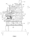
- Fig. 1 is a partial cross-sectional view taken along an axis, showing a schematic configuration of a sealing structure for a front cover of an engine (referred to simply as a "sealing structure” hereinafter), which is a cover made of resin according to an embodiment of the present invention
- Fig. 2 is a partial enlarged cross-sectional view of the sealing structure shown in Fig. 1 .
- an arrow a (see Fig. 1 ) direction in a direction of an axis x will be referred to as an outer side
- an arrow b (see Fig. 1 ) direction in the direction of the axis x will be referred to as an inner side.
- the outer side is the direction away from the inside of a front cover
- the inner side is the direction toward the inside of the front cover.
- a direction perpendicular to the axis x (which will also be referred to as "a radial direction")
- the direction away from the axis x (indicated by an arrow c in Fig. 1 ) will be referred to as an outer periphery side
- the direction toward the axis x indicated by an arrow d in Fig. 1
- an inner periphery side the direction away from the axis x
- a sealing structure 1 for a front cover of an engine includes a front cover 40 made of resin of an engine with a through-hole 41 in which a shaft part (a boss part 14 of a torsional damper 10 described later) is to be inserted, and a sealing apparatus 2 to seal between the through-hole 41 of the front cover 40 and the shaft part.
- the sealing apparatus 2 includes a support ring 20 that is made of resin and annular about the axis x and an elastic body part 30 that is made of an elastic material, annular about the axis x and attached to the support ring 20.
- the elastic body part 30 has an annular seal lip 31 that contacts the shaft part such that the shaft part is able to slide, and the support ring 20 is bonded to the front cover 40.
- the sealing structure 1 for a front cover of an engine according to the embodiment of the present invention will be specifically described.
- the sealing structure 1 for a front cover of an engine is applied to a front cover made of resin of an engine used for a vehicle, a general-purpose machine or the like, a torsional damper, and a sealing apparatus that seals an annular space between a boss part of the torsional damper serving as a shaft part and a through-hole of the front cover.
- a damper pulley 10 as the torsional damper 10 is fixed to one end of a crankshaft 51 of the engine by a bolt 52.
- the damper pulley 10 includes a hub 11, a pulley 12 as a mass body, and a damper elastic body 13 disposed between the hub 11 and the pulley 12.
- the hub 11 is an annular member centered about the axis x and includes a boss part 14 as a shaft part on the inner periphery side, a rim part 15 on the outer periphery side, and a disk part 16 having a substantially circular disk-like shape that connects the boss part 14 and the rim part 15 to each other.
- the hub 11 is molded or otherwise formed from a metal material, for example.
- the boss part 14 is an annular part that has a through-hole 14a and is centered about the axis x, and the disk part 16 extends in the outer periphery direction from an outer circumferential surface of an outer side part of the boss part 14.
- the boss part 14 has an outer circumferential surface 14b, which is a cylindrical outer periphery side surface of an inner side part of the boss part 14, and the outer circumferential surface 14b is a smooth surface and serves as a sealing surface for the sealing apparatus 2 as described later.
- the rim part 15 is an annular, or more specifically, cylindrical part centered about the axis x, and the rim part 15 is a part located further on the outer periphery side than the boss part 14, concentrically with the boss part 14.
- the disk part 16 extends in the inner periphery direction from an inner circumferential surface 15a, which is a surface of the rim part 15 on the inner periphery side.
- the damper elastic body 13 is in pressure-contact with an outer circumferential surface 15b, which is a surface of the rim part 15 on the outer periphery side.
- the disk part 16 extends between the boss part 14 and the rim part 15 and connects the boss part 14 and the rim part 15 to each other.
- the disk part 16 may extend in a direction perpendicular to the axis x or in a direction oblique to the axis x.
- the cross section of the disk part 16 taken along the axis x (also referred to simply as a "cross section") may be curved or straight.
- the disk part 16 has at least one window 16a, which is a through-hole penetrating the disk part 16 between the inner side and the outer side.
- four windows 16a are formed concentrically about the axis x and at regular angular intervals in the circumferential direction.
- the windows 16a are intended to reduce the weight of the hub 11 and thus the damper pulley 10.
- the damper pulley 10 may have no window 16a.
- the pulley 12 is an annular member centered about the axis x and is shaped to cover the hub 11 on the outer periphery side. More specifically, an inner circumferential surface 12a, which is a surface of the pulley 12 on the inner periphery side, has a shape that conforms with the shape of the outer circumferential surface 15b of the rim part 15 of the hub 11, and as shown in Fig. 1 , the pulley 12 is positioned in such a manner that the inner circumferential surface 12a is radially opposed at a distance to the outer circumferential surface 15b of the rim part 15.
- a plurality of annular V-shaped grooves 12c are formed so that a timing belt (not shown) can be wound around the pulley 12.
- the damper elastic body 13 is disposed between the pulley 12 and the rim part 15 of the hub 11.
- the damper elastic body 13 is a damper rubber member and is molded by cross-linking of a rubber-like elastic material having high heat resistance, high cold resistance and high fatigue strength.
- the damper elastic body 13 is press-fitted between the pulley 12 and the rim part 15 of the hub 11, and fitted and fastened between the inner circumferential surface 12a of the pulley 12 and the outer circumferential surface 15b of the rim part 15.
- the pulley 12 and the damper elastic body 13 form a damper section, and the natural frequency in the torsional direction of the damper section is tuned to corresponds to the natural frequency in the torsional direction of the crankshaft 51, which lies within a predetermined frequency range in which the torsional angle of the crankshaft 51 is at the maximum. That is, the inertial mass of the pulley 12 in the circumferential direction and the shear spring constant of the damper elastic body 13 in the torsional direction are adjusted so that the natural frequency in the torsional direction of the damper section corresponds to the natural frequency in the torsional direction of the crankshaft 51.
- the damper pulley 10 further has at least one torsional damper protrusion part, which is an annular part that protrudes in the direction of the axis x and forms a labyrinth seal L1 described later in cooperation with the front cover 40.
- the damper pulley 10 has two torsional damper protrusion parts (an outer periphery side protrusion part 17a and an inner periphery side protrusion part 17b).
- the outer periphery side protrusion part 17a and the inner periphery side protrusion part 17b are annular parts centered or substantially centered about the axis x that are provided on an inner side surface 16b, which is a disk-like surface facing the inner side that is located further toward the inner periphery side than the windows 16a of the disk part 16 of the hub 11, and protrude inwardly from the inner side surface 16b in the direction of the axis x.
- the outer periphery side protrusion part 17a is provided further on the outer periphery side than the inner periphery side protrusion part 17b, and a hub groove 11b, which is an annular groove that is centered or substantially centered on the axis x and radially arranged at regular or substantially regular intervals, is formed between outer periphery side protrusion part 17a and the inner periphery side protrusion part 17b.
- the damper pulley 10 is attached to one end of the crankshaft 51 of the engine. More specifically, as shown in Fig. 1 , the damper pulley 10 is fixed to the crankshaft 51 by inserting one end of the crankshaft 51 into the through-hole 14a of the boss part 14 of the hub 11 and screwing the bolt 52 into the crankshaft 51 from the outer side.
- the damper pulley 10 When attached to the crankshaft 51, the damper pulley 10 is in a state in which the inner part of the boss part 14 having the outer circumferential surface 14b is inserted in the through-hole 41 of the front cover 40, and there is an annular space (gap g1) between the outer circumferential surface 14b of the boss part 14 and the through-hole 41 of the front cover 40.
- the sealing apparatus 2 has the support ring 20 made of resin and the elastic body part 30 made of an elastic material attached to the support ring 20. As shown in Figs. 1 and 2 , in the sealing structure 1, the sealing apparatus 2 is bonded by welding to the front cover 40 at the support ring 20.
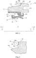
- Fig. 3 is a cross-sectional view of the sealing apparatus 2 taken along the axis x, schematically showing a configuration of the sealing apparatus 2 alone before the sealing apparatus 2 is welded to the front cover 40.
- the support ring 20 is an annular member made of resin centered or substantially centered about the axis x, and has an insert part 21, which is an annular part that is to be inserted into the through-hole 41 of the front cover 40, a bonding part 22, which is an annular part to be bonded by welding to the front cover 40, and an outer side part 23, which is an annular part that protrudes to the outer side from the through-hole 41 of the front cover 40.
- the support ring 20 is integrally made of a resin material, and the insert part 21, the bonding part 22 and the outer side part 23 are integrally-formed parts of the support ring 20.
- the insert part 21 extends along the axis x and has an outer circumferential surface 21a facing to the outer periphery side and an inner circumferential surface 21b facing to the inner periphery side.
- the insert part 21 in the sealing structure 1, is in the through-hole 41 of the front cover 40, and the outer circumferential surface 21a is shaped to guide the insert part 21 into the through-hole 41 when the support ring 20 is attached to the front cover 40, for example. More specifically, as shown in Fig.
- the outer circumferential surface 21a of the insert part 21 is a tapered surface having a diameter that decreases as progress from the outer side (the side toward the arrow a direction) toward the inner side (the side toward the arrow b direction) in the direction of the axis x.
- the diameter of an end portion (end portion 21c) on the outer side of the outer circumferential surface 21a is equal or substantially equal to the diameter of an inner circumferential surface 41a of the through-hole 41 of the front cover 40. This facilitates alignment between the through-hole 41 of the front cover 40 and the sealing apparatus 2.
- the bonding part 22 has an annular projection part 22a that protrudes in the direction of the axis x.
- the support ring 20 is bonded to the front cover 40 at the projection part 22a made molten, and the projection part 22a of the bonding part 22 is a part to be welded.
- the bonding part 22 is further provided with an annular recessed part 22b recessed in the direction of the axis x that is formed at least any of the inner periphery side or outer periphery side of the projection part 22a.
- one recessed part 22b is provided on the outer periphery side of the projection part 22a.
- Fig. 4 is a partial enlarged cross-sectional view showing an enlarged view of the bonding part 22 of the support ring 20 and its surroundings.
- the bonding part 22 has a bonding surface 22c, which is a surface that is annular about the axis x and faces to the inner side in the direction of the axis x, the projection part 22a protrudes toward the inner side from the bonding surface 22c, and the recessed part 22b is recessed toward the outer side from the bonding surface 22c.
- the bonding surface 22c is a planar surface that is perpendicular or substantially perpendicular to the axis x, for example.
- the bonding part 22 may have a plurality of projection parts 22a arranged in the radial direction.
- the outer side part 23 of the support ring 20 is a part that is located connected to the insert part 21 on the outer side of the insert part 21, in which the bonding part 22 is formed. That is, the outer side part 23 protrudes toward the outer periphery side beyond the insert part 21.
- a welding jig guide part 23a which is an annular recessed part that is recessed from the outer side toward the inner side, is further formed.
- the welding jig guide part 23a is a part in which a welding jig is fitted when welding the support ring 20 to the front cover 40 as described later.
- the elastic body part 30 is attached to the support ring 20 and, in the present embodiment, is integrally formed with the support ring 20 so as to cover the inner periphery side of the support ring 20.
- the elastic body part 30 is attached to the inner circumferential surface 21b of the insert part 21 of the support ring 20 and the annular protruding part 23b of the outer side part 23 that protrudes toward the inner periphery side.
- the elastic body part 30 has the seal lip 31 as described above, and has an annular dust lip 32 that is provided further on the outer side (the side toward the arrow a direction) than the seal lip 31 and extends in the direction of the axis x.
- the elastic body part 30 further has an annular lip waist part 33.
- the seal lip 31 is formed so that the outer circumferential surface 14b of the boss part 14 of the damper pulley 10 in the sealing structure 1 comes into contact with the seal lip 31 such that the outer circumferential surface 14b is able to slide.
- the dust lip 32 is provided further on the outer side than the seal lip 31 and is formed so that the outer circumferential surface 14b of the boss part 14 of the damper pulley 10 comes into contact with the dust lip 32 such that the outer circumferential surface 14b is able to slide.
- the lip waist part 33 is a part of the elastic body part 30 that supports the seal lip 31 and the dust lip 32.
- the seal lip 31 is a part that extends toward the inner side from the lip waist part 33 and an annular part centered or substantially centered about the axis x, and is formed to be opposed to the insert part 21 of the support ring 20.
- the seal lip 31 has, at an end portion thereof on the inner side, an annular wedge-like lip tip end portion 34 whose cross section protrudes toward the inner periphery side.
- the seal lip 31 further has, on the outer periphery side, an annular recessed part 35 at a position opposite to the lip tip end portion 34, and a garter spring 36 is fitted into the recessed part 35.
- the garter spring 36 presses the lip tip end portion 34 in the direction toward the axis x to exert a tightening force of a predetermined magnitude against the boss part 14 of the damper pulley 10 to the lip tip end portion 34 so that the lip tip end portion 34 follows a displacement of the boss part 14.
- the lip tip end portion 34 comes into contact with the outer circumferential surface 14b of the boss part 14 to seal between the sealing apparatus 2 and the boss part 14 as described later.
- the dust lip 32 extends toward the outer side and toward the axis x from the lip waist part 33, and more specifically, extends in the direction toward the outer side and the inner periphery side from the lip waist part 33, as shown in Fig. 3 .
- the dust lip 32 prevents entry of foreign matter, such as muddy water, sand, or dust, from the outer side toward the lip tip end portion 34.
- the dust lip 32 may be configured so that the dust lip 32 is not in contact with but is located close to the boss part 14 of the damper pulley 10.
- the elastic body part 30 is integrally made of an elastic material, and the seal lip 31, the dust lip 32, the lip waist part 33 and the other parts are parts of the elastic body part 30 that are integrally made of an elastic material.
- a resin material forming the support ring 20 is a weldable resin, such as a thermoplastic resin, as described later.
- the resin material forming the support ring 20 is a resin material that does not melt at the ambient temperature when the sealing structure 1 is in the usage state, that is, the ambient temperature when the engine is in the usage state.
- the resin material forming the support ring 20 is a hard thermoplastic synthetic resin material, such as polyamide, polyester, polypropylene, or ABS resin.
- the resin material forming the support ring 20 may be the same as the resin material forming the front cover 40.
- the elastic material forming the elastic body part 30 may be various rubber materials, for example.
- the various rubber materials include synthetic rubbers, such as nitrile rubber (NBR), hydrogenated nitrile rubber (H-NBR), acrylic rubber (ACM) or fluororubber (FKM).
- the support ring 20 is manufactured by injection molding, for example, and the elastic body part 30 is molded with a mold by cross-linking (vulcanization). In the cross-linking, the support ring 20 is placed inside the mold, the elastic body part 30 is bonded to the support ring 20 by cross-linking bonding, and then the elastic body part 30 is integrally molded with the support ring 20.
- the support ring 20 of the sealing apparatus 2 has the insert part 21 and the outer side part 23, is elongated in the direction of the axis x and can cover the elastic body part 30 on the inner periphery side of the support ring 20. Therefore, the support ring 20 can protect the elastic body part 30 from the outside when a plurality of sealing apparatuses 2 are transported in a state where the sealing apparatuses 2 are stacked in the direction of the axis x or when the sealing apparatus 2 is assembled. In this respect, it is preferable that the elastic body part 30 be provided at a position where the elastic body part 30 is hidden by the support ring 20 when the sealing apparatus 2 is viewed from the outer periphery side in the radial direction.
- the front cover 40 is made of a resin material, and the resin material may be a synthetic resin, such as polyamide, polyester, polypropylene or ABS resin.
- the through-hole 41 into which the crankshaft 51 and the boss part 14 of the damper pulley 10 are inserted, is formed.
- the annular gap g1 is formed between the inner circumferential surface 41a of the through-hole 41 and the outer circumferential surface 14b of the boss part 14, and the gap g1 is sealed by the sealing apparatus 2 welded to the front cover 40.
- the bonding part of the support ring 20 in the sealing structure 1 is bonded by welding to an outer side surface 42, which faces to the outer side of the front cover 40 at a location close to the through-hole 41.
- the front cover 40 further has a front cover protrusion part 43, which is an annular part that protrudes from the outer side surface 42 toward the disk part 16 of the hub 11 of the damper pulley 10.
- the front cover protrusion part 43 forms the labyrinth seal L1 described above in cooperation with the outer periphery side protrusion part 17a and the inner periphery side protrusion part 17b of the boss part 14 of the damper pulley 10. More specifically, as shown in Fig.
- the front cover protrusion part 43 is located in the hub groove 11b, which is an annular groove formed by the outer periphery side protrusion part 17a and the inner periphery side protrusion part 17b.
- the front cover protrusion part 43 is not in contact with the hub groove 11b. Therefore, as shown in Fig. 2 , an annular gap g2 having a U-shaped cross section is formed between the front cover protrusion part 43 and the hub groove 11b, so that the labyrinth seal L1 is formed between the front cover 40 and the damper pulley 10. From the viewpoint of improving the sealing performance of the labyrinth seal L1, it is preferable that the gap g2 between the front cover protrusion part 43 and the hub groove 11b is narrower.
- a method of bonding the support ring 20 of the sealing apparatus 2 to the front cover 40 will be described.
- a jig (not shown) is attached to the welding jig guide part 23a of the sealing apparatus 2 yet to be bonded shown in Fig. 3 , the sealing apparatus 2 is held at the jig, and the insert part 21 of the support ring 20 is inserted into the through-hole 41 of the front cover 40 so that the projection part 22a of the bonding part 22 of the support ring 20 abuts against the outer side surface 42 of the front cover 40.
- the projection part 22a of the bonding part 22 is made to vibrate while the projection part 22a is in pressure-contact with the outer side surface 42 of the front cover 40 to make the projection part 22a molten, thereby welding the support ring 20 to the outer side surface 42 of the front cover 40 at the molten projection part 22a of the bonding part 22.
- the means that makes the projection part 22a vibrate for welding may be the jig for holding the sealing apparatus 2 described above, other means that cause vibration, a means that applies ultrasonic wave or laser light, or other means.
- the annular recessed part 22b is formed in the bonding part 22, and part of the molten projection part 22a that is not used for the welding of the support ring 20 to the front cover 40 flows into the recessed part 22b when the support ring 20 is welded to the front cover 40. Therefore, the state of bonding between the support ring 20 and the front cover 40 can be kept good, and formation of a welding burr can be inhibited or prevented.
- the recessed part 22b is located on the outer periphery side of the projection part 22a in the bonding part 22 in the example shown in the drawings, the recessed part 22b may be located on the inner periphery side of the projection part 22a, or a plurality of recessed parts 22b may be formed. Recessed parts 22b may also be provided on the outer periphery side and inner periphery side of the projection part 22a.
- the welding jig guide part 23a to which a jig is to be attached is formed in the support ring 20 of the sealing apparatus 2, and the welding jig guide part 23a can improve the efficiency of the operation of attaching the sealing apparatus 2 to the front cover 40.
- the support ring 20 made of resin is bonded by welding to the front cover 40 made of resin.
- the bonding forms a seal between the sealing apparatus 2 and the front cover 40. Therefore, the difference in coefficient of thermal expansion between the sealed parts of the support ring 20 and front cover 40 can be reduced, the state of bonding between the support ring 20 and the front cover 40 can be stabilized, and the state of sealing between the sealing apparatus 2 and the front cover 40 can be stably maintained.
- the sealing structure 1 no gap is formed between the support ring 20 and the front cover 40, and a reduction of the sealing performance in response to the usage state can be prevented. Therefore, it is preferable that the difference in coefficient of thermal expansion between the resin material forming the support ring 20 and the resin material forming the front cover 40 be small.
- the relative positions of the support ring 20 and the boss part 14 of the damper pulley 10 can vary because of the difference in coefficient of thermal expansion, and therefore, depending on the state of the ambient temperature, the dust lip 32 may come off the outer circumferential surface 14b of the boss part 14 or the distance between the dust lip 32 and the outer circumferential surface 14b of the boss part 14 may increase, and foreign matter may become more likely to enter into the side of the seal lip 31.
- the sealing structure 1 has the labyrinth seal L1 on the upstream side of the dust lip 32 along the path of entry of foreign matter, and entry of foreign matter is blocked by the labyrinth seal L1.
- the labyrinth seal L1 can prevent entry of foreign matter and compensate for the decline of the performance of the dust lip 32.
- the labyrinth seal L1 can further prevent entry of foreign matter.
- the sealing structure 1 for a front cover of an engine according to the embodiment of the present invention can maintain the sealing performance regardless of the usage state thereof.
- the present invention is not limited to the embodiment of the present invention described above but includes any aspects to be included in the concept and claims of the present invention.
- the components described above may be selectively combined as required in order to solve at least some of the problems described above or to achieve at least some of the effects described above.
- the shape, material, position, size, manufacturing method or the like of each component in the embodiment described above can be modified as required depending on the specific implementation of the present invention.
- the configuration of the labyrinth seal positioned upstream of the dust lip 32 along the path of entry of foreign matter in the present invention is not limited to the labyrinth seal L1 described above but may be other configurations.
- the labyrinth seal L1 is formed by the front cover protrusion part 43 being positioned in the hub groove 11b formed by the outer periphery side protrusion part 17a and the inner periphery side protrusion part 17b
- a labyrinth seal may be formed by a gap formed by one protrusion and another protrusion opposed to each other.
- the damper pulley 10 may have only one of the outer periphery side protrusion part 17a and the inner periphery side protrusion part 17b, and the labyrinth seal L1 may be formed by the one of the outer periphery side protrusion part 17a and the inner periphery side protrusion part 17b and the front cover protrusion part 43.
- the front cover 40 may have two front cover protrusion parts 43, which form an annular groove as with the outer periphery side protrusion part 17a and the inner periphery side protrusion part 17b, and the outer periphery side protrusion part 17a or inner periphery side protrusion part 17b may be positioned in the groove to form a labyrinth seal L1.
- the damper pulley 10 may have only one of the outer periphery side protrusion part 17a and the inner periphery side protrusion part 17b.
- the front cover 40 may have a plurality of front cover protrusion parts 43
- the damper pulley 10 may have a plurality of torsional damper protrusion parts (outer periphery side protrusion part 17a or inner periphery side protrusion part 17b), and gaps between the plurality of protrusion parts may form a labyrinth seal L1.
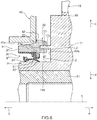
- the support ring 20 may form a labyrinth seal in cooperation with the damper pulley 10.
- a labyrinth seal L2 may be provided between the support ring 20 and the damper pulley 10.
- annular protrusion part 17c that is to be positioned in the welding jig guide part 23a of the outer side part 23 of the support ring 20 may be formed on the inner side surface 16b of the disk part 16 of the damper pulley 10, and an annular gap g3 having an U-shaped cross section may be formed between the protrusion part 17c and the welding jig guide part 23a to form a labyrinth seal L2 between the support ring 20 and the damper pulley 10.
- the labyrinth seal L2 between the support ring 20 and the damper pulley 10 may have another configuration.
- the labyrinth seal L2 may be formed by the protrusion part 17c forming an annular gap, being opposed to the outer circumferential surface or inner circumferential surface of the outer side part 23 of the support ring 20 on the outer periphery side or inner periphery side, respectively.
- the damper pulley 10 may have a hub groove 11b instead of the protrusion part 17c, and the support ring 20 may have an annular protrusion part that is to be positioned in the hub groove 11b to form the labyrinth seal L2.
- the support ring 20 may be bonded to the front cover 40 with an adhesive.
- the support ring 20 does not have to have the projection part 22a and the recessed part 22b in the bonding part 22 and has only the bonding surface 22c.
- the bonding part 22 may have the recessed part 22b as a space to accommodate the adhesive.
- the support ring in the sealing apparatus according to the present invention is not limited to the support ring 20 described above but may have other configurations as far as the elastic body part 30 can be attached and the support ring 20 can be bonded to the front cover 40.
- the modifications of the sealing apparatus shown in Figs. 7 and 8 are also possible.
- a sealing apparatus 3 according to a first modification has a support ring 24, which is different from the support ring 20 of the sealing apparatus 2, and the support ring 24 does not have the insert part 21.
- a sealing apparatus 4 according to a second modification has a support ring 25, which is different from the support ring 20 of the sealing apparatus 2, and the support ring 25 does not have the insert part 21 and the outer side part 23.
- a part of the support ring 20 to be welded to the front cover 40 is not limited to the part (the bonding part 22) described above.
- the bonding part 22 may be located at another position on the support ring 20, or the support ring 20 may have a plurality of bonding parts 22.
- the support ring 20 may have another bonding part 22 on an inner side surface 21d of the insert part 21.
- a part to which the bonding part 22 of the insert part 21 is to be welded is provided on the front cover 40.
- the cover made of resin according to the present invention is not limited to the front cover of an engine but may be another cover made of resin.
- the present invention can be applied to a sealing structure between a shaft part that makes a motion, such as a rotational motion or a reciprocating motion, and a cover made of resin, and the cover made of resin according to the present invention may be a cover made of resin of a transmission of an automobile or the like, a cover made of resin of a differential mechanism of an automobile or the like, a cover made of resin of a steering mechanism, a cover made of resin of a motor, or a cover made of resin of a speed reducer, for example.
- the present invention can be applied to a shaft part that makes a motion, such as a rotational motion or a reciprocating motion, and a cover made of resin that has a space in which the shaft part is to be inserted, in order to seal the gap between the shaft part and the cover made of resin.
Landscapes
- Engineering & Computer Science (AREA)
- Mechanical Engineering (AREA)
- General Engineering & Computer Science (AREA)
- Physics & Mathematics (AREA)
- Thermal Sciences (AREA)
- Sealing Using Fluids, Sealing Without Contact, And Removal Of Oil (AREA)
- Sealing Devices (AREA)
- Cylinder Crankcases Of Internal Combustion Engines (AREA)
- Sealing With Elastic Sealing Lips (AREA)
Applications Claiming Priority (2)
| Application Number | Priority Date | Filing Date | Title |
|---|---|---|---|
| JP2018159351 | 2018-08-28 | ||
| PCT/JP2019/031669 WO2020045062A1 (fr) | 2018-08-28 | 2019-08-09 | Structure d'étanchéité pour capot en résine |
Publications (2)
| Publication Number | Publication Date |
|---|---|
| EP3845780A1 true EP3845780A1 (fr) | 2021-07-07 |
| EP3845780A4 EP3845780A4 (fr) | 2022-05-11 |
Family
ID=69644913
Family Applications (1)
| Application Number | Title | Priority Date | Filing Date |
|---|---|---|---|
| EP19856169.8A Pending EP3845780A4 (fr) | 2018-08-28 | 2019-08-09 | Structure d'étanchéité pour capot en résine |
Country Status (5)
| Country | Link |
|---|---|
| US (1) | US11668397B2 (fr) |
| EP (1) | EP3845780A4 (fr) |
| JP (1) | JP7062072B2 (fr) |
| CN (1) | CN112166268B (fr) |
| WO (1) | WO2020045062A1 (fr) |
Families Citing this family (3)
| Publication number | Priority date | Publication date | Assignee | Title |
|---|---|---|---|---|
| JP7448346B2 (ja) * | 2019-12-09 | 2024-03-12 | 日産自動車株式会社 | 内燃機関のチェーンケース |
| JP7480682B2 (ja) * | 2020-11-17 | 2024-05-10 | トヨタ紡織株式会社 | 内燃機関のカバー |
| US11873816B2 (en) * | 2021-12-14 | 2024-01-16 | Regi U.S., Inc. | Rotary vane device with longitudinally extending seals |
Family Cites Families (25)
| Publication number | Priority date | Publication date | Assignee | Title |
|---|---|---|---|---|
| JPH05177711A (ja) | 1991-12-27 | 1993-07-20 | Tsuchiya Mfg Co Ltd | 合成樹脂部材の溶着方法 |
| JP2579497Y2 (ja) * | 1992-03-09 | 1998-08-27 | エヌオーケー株式会社 | 密封装置 |
| JPH06285994A (ja) * | 1993-03-31 | 1994-10-11 | Tsuchiya Mfg Co Ltd | 合成樹脂部材の溶着方法 |
| US5329898A (en) | 1993-05-05 | 1994-07-19 | Freudenerg-Nok General Partnership | Shaft seal and bore assembly |
| JPH11216776A (ja) | 1998-02-02 | 1999-08-10 | Nissan Motor Co Ltd | 振動溶着リブ構造および振動溶着方法 |
| JP4639619B2 (ja) * | 2004-03-23 | 2011-02-23 | Nok株式会社 | 往復動軸用密封装置 |
| JP2006242000A (ja) * | 2005-02-28 | 2006-09-14 | Toyota Motor Corp | バルブケース及びシリンダヘッドカバーの形成方法 |
| JP2008057756A (ja) * | 2006-09-04 | 2008-03-13 | Kayaba Ind Co Ltd | 往復動用オイルシール |
| JP5041137B2 (ja) | 2007-01-29 | 2012-10-03 | Nok株式会社 | 密封装置 |
| JP2008309263A (ja) * | 2007-06-15 | 2008-12-25 | Nok Corp | 密封装置 |
| JP2009103142A (ja) | 2007-10-19 | 2009-05-14 | Toyota Motor Corp | シール装置 |
| JP5072653B2 (ja) | 2008-02-29 | 2012-11-14 | ダイキョーニシカワ株式会社 | オイルセパレータの構造 |
| JP5585754B2 (ja) * | 2009-03-31 | 2014-09-10 | Nok株式会社 | シール部品の製造方法及び金型 |
| JP5556355B2 (ja) * | 2010-05-18 | 2014-07-23 | Nok株式会社 | ダンパ |
| EP2952788B1 (fr) * | 2013-01-29 | 2017-10-04 | Eagle Industry Co., Ltd. | Dispositif d'étanchéité |
| JP6241188B2 (ja) * | 2013-10-16 | 2017-12-06 | 日本精工株式会社 | エンコーダ付組み合わせシールリング及びエンコーダ付転がり軸受ユニット |
| WO2016009803A1 (fr) * | 2014-07-17 | 2016-01-21 | イーグル工業株式会社 | Dispositif d'étanchéité |
| WO2016088872A1 (fr) * | 2014-12-04 | 2016-06-09 | Nok株式会社 | Structure d'étanchéité utilisant un amortisseur à torsion et un joint d'étanchéité à huile |
| JP6474030B2 (ja) | 2014-12-25 | 2019-02-27 | Nok株式会社 | トーショナルダンパとオイルシールとのラビリンス構造 |
| WO2016111129A1 (fr) | 2015-01-07 | 2016-07-14 | Nok株式会社 | Structure d'étanchéité utilisant un amortisseur de torsion et un joint d'huile |
| JP6498472B2 (ja) | 2015-02-24 | 2019-04-10 | 株式会社荒井製作所 | 密封装置 |
| JP6103002B2 (ja) * | 2015-08-20 | 2017-03-29 | 日本精工株式会社 | エンコーダ及び組み合わせシールリング付ハブユニット |
| JP6864624B2 (ja) | 2015-09-25 | 2021-04-28 | Nok株式会社 | ディファレンシャル機構用密封装置 |
| JP6747863B2 (ja) * | 2015-09-28 | 2020-08-26 | Nok株式会社 | 密封装置 |
| BR112018073599A2 (pt) * | 2016-05-18 | 2019-02-26 | Nok Corporation | estrutura de vedação com cavidade anular e dispositivo de vedação |
-
2019
- 2019-08-09 WO PCT/JP2019/031669 patent/WO2020045062A1/fr not_active Ceased
- 2019-08-09 JP JP2020539313A patent/JP7062072B2/ja active Active
- 2019-08-09 EP EP19856169.8A patent/EP3845780A4/fr active Pending
- 2019-08-09 CN CN201980035379.0A patent/CN112166268B/zh active Active
- 2019-08-09 US US17/059,167 patent/US11668397B2/en active Active
Also Published As
| Publication number | Publication date |
|---|---|
| JP7062072B2 (ja) | 2022-05-02 |
| CN112166268B (zh) | 2023-01-31 |
| US11668397B2 (en) | 2023-06-06 |
| JPWO2020045062A1 (ja) | 2021-03-11 |
| EP3845780A4 (fr) | 2022-05-11 |
| WO2020045062A1 (fr) | 2020-03-05 |
| US20210215251A1 (en) | 2021-07-15 |
| CN112166268A (zh) | 2021-01-01 |
Similar Documents
| Publication | Publication Date | Title |
|---|---|---|
| EP3242054B1 (fr) | Structure d'étanchéité avec un amortisseur de torsion et un joint d'huile | |
| US10663031B2 (en) | Sealing structure with annular pocket and sealing apparatus | |
| EP2913556B1 (fr) | Dispositif de palier à point d'appui pour bras de poulie | |
| EP3845780A1 (fr) | Structure d'étanchéité pour capot en résine | |
| US20070249442A1 (en) | Belt pulley with integrated torsional oscillation damper and process for producing same | |
| JP5791875B2 (ja) | ダンパ | |
| JP2017526883A (ja) | 1つ以上のエラストマ部材を収容したカートリッジを備えたドライブシステムのための装置 | |
| US8047328B1 (en) | Plastic muffler and method for making same | |
| JP2017214994A (ja) | 環状のポケットと密封装置とを用いた密封構造、および、トーショナルダンパとオイルシールとを用いた密封構造 | |
| JP6521480B2 (ja) | トーショナルダンパとオイルシールとによる密封構造 | |
| EP3447345B1 (fr) | Structure d'étanchéité faisant appel à un amortisseur et à un joint d'huile | |
| JPWO2019194088A1 (ja) | 気流発生構造体および密封構造 | |
| JP7178930B2 (ja) | トーショナルダンパー | |
| JP5945496B2 (ja) | ダンパ付プーリ | |
| JP7527930B2 (ja) | 密封装置 | |
| JP6474030B2 (ja) | トーショナルダンパとオイルシールとのラビリンス構造 | |
| JP7337641B2 (ja) | 環状のポケットと密封装置とを用いた密封構造、及び、トーショナルダンパとオイルシールとを用いた密封構造 | |
| JP7285683B2 (ja) | 密封装置、及び、密封構造 | |
| JP2021028527A (ja) | トーショナルダンパ | |
| JP2020193659A (ja) | トーショナルダンパ |
Legal Events
| Date | Code | Title | Description |
|---|---|---|---|
| STAA | Information on the status of an ep patent application or granted ep patent |
Free format text: STATUS: THE INTERNATIONAL PUBLICATION HAS BEEN MADE |
|
| STAA | Information on the status of an ep patent application or granted ep patent |
Free format text: STATUS: REQUEST FOR EXAMINATION WAS MADE |
|
| PUAI | Public reference made under article 153(3) epc to a published international application that has entered the european phase |
Free format text: ORIGINAL CODE: 0009012 |
|
| 17P | Request for examination filed |
Effective date: 20201127 |
|
| AK | Designated contracting states |
Kind code of ref document: A1 Designated state(s): AL AT BE BG CH CY CZ DE DK EE ES FI FR GB GR HR HU IE IS IT LI LT LU LV MC MK MT NL NO PL PT RO RS SE SI SK SM TR |
|
| DAV | Request for validation of the european patent (deleted) | ||
| DAX | Request for extension of the european patent (deleted) | ||
| A4 | Supplementary search report drawn up and despatched |
Effective date: 20220407 |
|
| RIC1 | Information provided on ipc code assigned before grant |
Ipc: B29L 31/00 20060101ALI20220402BHEP Ipc: B29L 31/26 20060101ALI20220402BHEP Ipc: F16J 15/3252 20160101ALI20220402BHEP Ipc: B29C 65/00 20060101ALI20220402BHEP Ipc: B29C 65/48 20060101ALI20220402BHEP Ipc: B29C 65/16 20060101ALI20220402BHEP Ipc: B29C 65/08 20060101ALI20220402BHEP Ipc: B29C 65/06 20060101ALI20220402BHEP Ipc: F16J 15/447 20060101ALI20220402BHEP Ipc: F02F 11/00 20060101ALI20220402BHEP Ipc: F02F 7/00 20060101ALI20220402BHEP Ipc: F16J 15/3204 20160101AFI20220402BHEP |
|
| STAA | Information on the status of an ep patent application or granted ep patent |
Free format text: STATUS: EXAMINATION IS IN PROGRESS |
|
| 17Q | First examination report despatched |
Effective date: 20241018 |