WO2020045062A1 - Sealing structure for resin cover - Google Patents
Sealing structure for resin cover Download PDFInfo
- Publication number
- WO2020045062A1 WO2020045062A1 PCT/JP2019/031669 JP2019031669W WO2020045062A1 WO 2020045062 A1 WO2020045062 A1 WO 2020045062A1 JP 2019031669 W JP2019031669 W JP 2019031669W WO 2020045062 A1 WO2020045062 A1 WO 2020045062A1
- Authority
- WO
- WIPO (PCT)
- Prior art keywords
- support ring
- annular
- resin cover
- protrusion
- front cover
- Prior art date
Links
Images


Classifications
-
- F—MECHANICAL ENGINEERING; LIGHTING; HEATING; WEAPONS; BLASTING
- F16—ENGINEERING ELEMENTS AND UNITS; GENERAL MEASURES FOR PRODUCING AND MAINTAINING EFFECTIVE FUNCTIONING OF MACHINES OR INSTALLATIONS; THERMAL INSULATION IN GENERAL
- F16J—PISTONS; CYLINDERS; SEALINGS
- F16J15/00—Sealings
- F16J15/16—Sealings between relatively-moving surfaces
- F16J15/32—Sealings between relatively-moving surfaces with elastic sealings, e.g. O-rings
- F16J15/3204—Sealings between relatively-moving surfaces with elastic sealings, e.g. O-rings with at least one lip
-
- F—MECHANICAL ENGINEERING; LIGHTING; HEATING; WEAPONS; BLASTING
- F16—ENGINEERING ELEMENTS AND UNITS; GENERAL MEASURES FOR PRODUCING AND MAINTAINING EFFECTIVE FUNCTIONING OF MACHINES OR INSTALLATIONS; THERMAL INSULATION IN GENERAL
- F16J—PISTONS; CYLINDERS; SEALINGS
- F16J15/00—Sealings
- F16J15/16—Sealings between relatively-moving surfaces
- F16J15/32—Sealings between relatively-moving surfaces with elastic sealings, e.g. O-rings
- F16J15/3248—Sealings between relatively-moving surfaces with elastic sealings, e.g. O-rings provided with casings or supports
- F16J15/3252—Sealings between relatively-moving surfaces with elastic sealings, e.g. O-rings provided with casings or supports with rigid casings or supports
-
- B—PERFORMING OPERATIONS; TRANSPORTING
- B29—WORKING OF PLASTICS; WORKING OF SUBSTANCES IN A PLASTIC STATE IN GENERAL
- B29C—SHAPING OR JOINING OF PLASTICS; SHAPING OF MATERIAL IN A PLASTIC STATE, NOT OTHERWISE PROVIDED FOR; AFTER-TREATMENT OF THE SHAPED PRODUCTS, e.g. REPAIRING
- B29C65/00—Joining or sealing of preformed parts, e.g. welding of plastics materials; Apparatus therefor
- B29C65/02—Joining or sealing of preformed parts, e.g. welding of plastics materials; Apparatus therefor by heating, with or without pressure
- B29C65/06—Joining or sealing of preformed parts, e.g. welding of plastics materials; Apparatus therefor by heating, with or without pressure using friction, e.g. spin welding
-
- B—PERFORMING OPERATIONS; TRANSPORTING
- B29—WORKING OF PLASTICS; WORKING OF SUBSTANCES IN A PLASTIC STATE IN GENERAL
- B29C—SHAPING OR JOINING OF PLASTICS; SHAPING OF MATERIAL IN A PLASTIC STATE, NOT OTHERWISE PROVIDED FOR; AFTER-TREATMENT OF THE SHAPED PRODUCTS, e.g. REPAIRING
- B29C66/00—General aspects of processes or apparatus for joining preformed parts
- B29C66/01—General aspects dealing with the joint area or with the area to be joined
- B29C66/05—Particular design of joint configurations
- B29C66/10—Particular design of joint configurations particular design of the joint cross-sections
- B29C66/13—Single flanged joints; Fin-type joints; Single hem joints; Edge joints; Interpenetrating fingered joints; Other specific particular designs of joint cross-sections not provided for in groups B29C66/11 - B29C66/12
- B29C66/131—Single flanged joints, i.e. one of the parts to be joined being rigid and flanged in the joint area
-
- B—PERFORMING OPERATIONS; TRANSPORTING
- B29—WORKING OF PLASTICS; WORKING OF SUBSTANCES IN A PLASTIC STATE IN GENERAL
- B29C—SHAPING OR JOINING OF PLASTICS; SHAPING OF MATERIAL IN A PLASTIC STATE, NOT OTHERWISE PROVIDED FOR; AFTER-TREATMENT OF THE SHAPED PRODUCTS, e.g. REPAIRING
- B29C66/00—General aspects of processes or apparatus for joining preformed parts
- B29C66/01—General aspects dealing with the joint area or with the area to be joined
- B29C66/05—Particular design of joint configurations
- B29C66/302—Particular design of joint configurations the area to be joined comprising melt initiators
- B29C66/3022—Particular design of joint configurations the area to be joined comprising melt initiators said melt initiators being integral with at least one of the parts to be joined
- B29C66/30223—Particular design of joint configurations the area to be joined comprising melt initiators said melt initiators being integral with at least one of the parts to be joined said melt initiators being rib-like
-
- B—PERFORMING OPERATIONS; TRANSPORTING
- B29—WORKING OF PLASTICS; WORKING OF SUBSTANCES IN A PLASTIC STATE IN GENERAL
- B29C—SHAPING OR JOINING OF PLASTICS; SHAPING OF MATERIAL IN A PLASTIC STATE, NOT OTHERWISE PROVIDED FOR; AFTER-TREATMENT OF THE SHAPED PRODUCTS, e.g. REPAIRING
- B29C66/00—General aspects of processes or apparatus for joining preformed parts
- B29C66/01—General aspects dealing with the joint area or with the area to be joined
- B29C66/32—Measures for keeping the burr form under control; Avoiding burr formation; Shaping the burr
- B29C66/322—Providing cavities in the joined article to collect the burr
-
- B—PERFORMING OPERATIONS; TRANSPORTING
- B29—WORKING OF PLASTICS; WORKING OF SUBSTANCES IN A PLASTIC STATE IN GENERAL
- B29C—SHAPING OR JOINING OF PLASTICS; SHAPING OF MATERIAL IN A PLASTIC STATE, NOT OTHERWISE PROVIDED FOR; AFTER-TREATMENT OF THE SHAPED PRODUCTS, e.g. REPAIRING
- B29C66/00—General aspects of processes or apparatus for joining preformed parts
- B29C66/50—General aspects of joining tubular articles; General aspects of joining long products, i.e. bars or profiled elements; General aspects of joining single elements to tubular articles, hollow articles or bars; General aspects of joining several hollow-preforms to form hollow or tubular articles
- B29C66/51—Joining tubular articles, profiled elements or bars; Joining single elements to tubular articles, hollow articles or bars; Joining several hollow-preforms to form hollow or tubular articles
- B29C66/53—Joining single elements to tubular articles, hollow articles or bars
- B29C66/532—Joining single elements to the wall of tubular articles, hollow articles or bars
- B29C66/5324—Joining single elements to the wall of tubular articles, hollow articles or bars said single elements being substantially annular, i.e. of finite length
- B29C66/53245—Joining single elements to the wall of tubular articles, hollow articles or bars said single elements being substantially annular, i.e. of finite length said articles being hollow
-
- B—PERFORMING OPERATIONS; TRANSPORTING
- B29—WORKING OF PLASTICS; WORKING OF SUBSTANCES IN A PLASTIC STATE IN GENERAL
- B29C—SHAPING OR JOINING OF PLASTICS; SHAPING OF MATERIAL IN A PLASTIC STATE, NOT OTHERWISE PROVIDED FOR; AFTER-TREATMENT OF THE SHAPED PRODUCTS, e.g. REPAIRING
- B29C66/00—General aspects of processes or apparatus for joining preformed parts
- B29C66/50—General aspects of joining tubular articles; General aspects of joining long products, i.e. bars or profiled elements; General aspects of joining single elements to tubular articles, hollow articles or bars; General aspects of joining several hollow-preforms to form hollow or tubular articles
- B29C66/51—Joining tubular articles, profiled elements or bars; Joining single elements to tubular articles, hollow articles or bars; Joining several hollow-preforms to form hollow or tubular articles
- B29C66/53—Joining single elements to tubular articles, hollow articles or bars
- B29C66/534—Joining single elements to open ends of tubular or hollow articles or to the ends of bars
- B29C66/5344—Joining single elements to open ends of tubular or hollow articles or to the ends of bars said single elements being substantially annular, i.e. of finite length, e.g. joining flanges to tube ends
-
- B—PERFORMING OPERATIONS; TRANSPORTING
- B29—WORKING OF PLASTICS; WORKING OF SUBSTANCES IN A PLASTIC STATE IN GENERAL
- B29C—SHAPING OR JOINING OF PLASTICS; SHAPING OF MATERIAL IN A PLASTIC STATE, NOT OTHERWISE PROVIDED FOR; AFTER-TREATMENT OF THE SHAPED PRODUCTS, e.g. REPAIRING
- B29C66/00—General aspects of processes or apparatus for joining preformed parts
- B29C66/70—General aspects of processes or apparatus for joining preformed parts characterised by the composition, physical properties or the structure of the material of the parts to be joined; Joining with non-plastics material
- B29C66/73—General aspects of processes or apparatus for joining preformed parts characterised by the composition, physical properties or the structure of the material of the parts to be joined; Joining with non-plastics material characterised by the intensive physical properties of the material of the parts to be joined, by the optical properties of the material of the parts to be joined, by the extensive physical properties of the parts to be joined, by the state of the material of the parts to be joined or by the material of the parts to be joined being a thermoplastic or a thermoset
- B29C66/731—General aspects of processes or apparatus for joining preformed parts characterised by the composition, physical properties or the structure of the material of the parts to be joined; Joining with non-plastics material characterised by the intensive physical properties of the material of the parts to be joined, by the optical properties of the material of the parts to be joined, by the extensive physical properties of the parts to be joined, by the state of the material of the parts to be joined or by the material of the parts to be joined being a thermoplastic or a thermoset characterised by the intensive physical properties of the material of the parts to be joined
- B29C66/7311—Thermal properties
- B29C66/73111—Thermal expansion coefficient
- B29C66/73112—Thermal expansion coefficient of different thermal expansion coefficient, i.e. the thermal expansion coefficient of one of the parts to be joined being different from the thermal expansion coefficient of the other part
-
- F—MECHANICAL ENGINEERING; LIGHTING; HEATING; WEAPONS; BLASTING
- F16—ENGINEERING ELEMENTS AND UNITS; GENERAL MEASURES FOR PRODUCING AND MAINTAINING EFFECTIVE FUNCTIONING OF MACHINES OR INSTALLATIONS; THERMAL INSULATION IN GENERAL
- F16J—PISTONS; CYLINDERS; SEALINGS
- F16J15/00—Sealings
- F16J15/44—Free-space packings
- F16J15/447—Labyrinth packings
- F16J15/4476—Labyrinth packings with radial path
-
- B—PERFORMING OPERATIONS; TRANSPORTING
- B29—WORKING OF PLASTICS; WORKING OF SUBSTANCES IN A PLASTIC STATE IN GENERAL
- B29C—SHAPING OR JOINING OF PLASTICS; SHAPING OF MATERIAL IN A PLASTIC STATE, NOT OTHERWISE PROVIDED FOR; AFTER-TREATMENT OF THE SHAPED PRODUCTS, e.g. REPAIRING
- B29C65/00—Joining or sealing of preformed parts, e.g. welding of plastics materials; Apparatus therefor
- B29C65/02—Joining or sealing of preformed parts, e.g. welding of plastics materials; Apparatus therefor by heating, with or without pressure
- B29C65/08—Joining or sealing of preformed parts, e.g. welding of plastics materials; Apparatus therefor by heating, with or without pressure using ultrasonic vibrations
-
- B—PERFORMING OPERATIONS; TRANSPORTING
- B29—WORKING OF PLASTICS; WORKING OF SUBSTANCES IN A PLASTIC STATE IN GENERAL
- B29C—SHAPING OR JOINING OF PLASTICS; SHAPING OF MATERIAL IN A PLASTIC STATE, NOT OTHERWISE PROVIDED FOR; AFTER-TREATMENT OF THE SHAPED PRODUCTS, e.g. REPAIRING
- B29C65/00—Joining or sealing of preformed parts, e.g. welding of plastics materials; Apparatus therefor
- B29C65/02—Joining or sealing of preformed parts, e.g. welding of plastics materials; Apparatus therefor by heating, with or without pressure
- B29C65/14—Joining or sealing of preformed parts, e.g. welding of plastics materials; Apparatus therefor by heating, with or without pressure using wave energy, i.e. electromagnetic radiation, or particle radiation
- B29C65/16—Laser beams
-
- B—PERFORMING OPERATIONS; TRANSPORTING
- B29—WORKING OF PLASTICS; WORKING OF SUBSTANCES IN A PLASTIC STATE IN GENERAL
- B29C—SHAPING OR JOINING OF PLASTICS; SHAPING OF MATERIAL IN A PLASTIC STATE, NOT OTHERWISE PROVIDED FOR; AFTER-TREATMENT OF THE SHAPED PRODUCTS, e.g. REPAIRING
- B29C65/00—Joining or sealing of preformed parts, e.g. welding of plastics materials; Apparatus therefor
- B29C65/48—Joining or sealing of preformed parts, e.g. welding of plastics materials; Apparatus therefor using adhesives, i.e. using supplementary joining material; solvent bonding
-
- B—PERFORMING OPERATIONS; TRANSPORTING
- B29—WORKING OF PLASTICS; WORKING OF SUBSTANCES IN A PLASTIC STATE IN GENERAL
- B29L—INDEXING SCHEME ASSOCIATED WITH SUBCLASS B29C, RELATING TO PARTICULAR ARTICLES
- B29L2031/00—Other particular articles
- B29L2031/26—Sealing devices, e.g. packaging for pistons or pipe joints
-
- B—PERFORMING OPERATIONS; TRANSPORTING
- B29—WORKING OF PLASTICS; WORKING OF SUBSTANCES IN A PLASTIC STATE IN GENERAL
- B29L—INDEXING SCHEME ASSOCIATED WITH SUBCLASS B29C, RELATING TO PARTICULAR ARTICLES
- B29L2031/00—Other particular articles
- B29L2031/748—Machines or parts thereof not otherwise provided for
- B29L2031/749—Motors
-
- F—MECHANICAL ENGINEERING; LIGHTING; HEATING; WEAPONS; BLASTING
- F02—COMBUSTION ENGINES; HOT-GAS OR COMBUSTION-PRODUCT ENGINE PLANTS
- F02F—CYLINDERS, PISTONS OR CASINGS, FOR COMBUSTION ENGINES; ARRANGEMENTS OF SEALINGS IN COMBUSTION ENGINES
- F02F7/00—Casings, e.g. crankcases or frames
- F02F7/0065—Shape of casings for other machine parts and purposes, e.g. utilisation purposes, safety
- F02F7/0073—Adaptations for fitting the engine, e.g. front-plates or bell-housings
- F02F2007/0078—Covers for belt transmissions
Definitions
- the present invention relates to a sealing structure in a resin cover, and more particularly to a sealing structure using a sealing device between a moving member in a front cover and the like of a resin engine.
- a through hole is provided in the front cover of the engine that covers the accessories and the timing chain attached to the side of the clan case, and the end of the crankshaft protrudes outside through this through hole.
- the torsion damper is attached to this end.
- an annular space is formed between the through hole and the end of the crankshaft or the boss of the torsional damper, and an oil seal as a sealing device is used to seal this space.
- the oil seal is fixed to the front cover by being pressed into a through hole of the front cover and compressing a rubber material on an outer peripheral side (for example, see Patent Document 1).
- a front cover of an engine is made of a metal such as an aluminum alloy.
- resinization of the front cover of the engine has been studied.
- Resin molded products have large dimensional tolerances, and resins have large coefficients of thermal expansion and creep deformation. For this reason, when a resin front cover is used in the engine, there is a concern that a gap may be formed between the oil seal press-fit into the through hole and the front cover. In particular, due to the difference in the coefficient of thermal expansion between the rubber material of the oil seal and the resin material of the front cover, when the front cover thermally expands, the gap between the inner peripheral surface of the through hole of the front cover and the outer peripheral surface of the oil seal is increased. A gap may be formed between them.
- a sealing structure of a resin cover such as a front cover of a resin engine
- a configuration capable of maintaining the sealing performance irrespective of a use condition such as an ambient temperature has been required.
- the present invention has been made in view of the above-described problems, and an object of the present invention is to provide a sealing structure in a resin cover that can maintain sealing performance regardless of a use state.
- the sealing structure in the resin cover according to the present invention includes a resin cover provided with a through hole through which a shaft portion is inserted, a through hole of the resin cover, and the shaft.
- a sealing device for sealing between the parts comprises a ring-shaped resin support ring around an axis, and a ring-shaped elastic body around the axis attached to the support ring.
- the support ring is joined to the resin cover by welding.
- a joining portion of the support ring which is a portion joined to the resin cover, is annular around the axis, and the joining portion is
- the support ring has an annular protrusion that is convex in the axial direction, and the support ring is joined to the resin cover via the melted protrusion.
- the support ring is provided with an annular concave portion that is concave in the axial direction on at least one of an inner peripheral side and an outer peripheral side of the protrusion. I have.
- the support ring is joined to the resin cover with an adhesive.
- the shaft portion is a boss portion of a torsional damper
- the elastic body has an annular dust lip
- the support ring A labyrinth seal is formed with the torsion damper.
- the support ring has at least one support ring protrusion that is an annular portion that protrudes in the axial direction, and the torsion damper is And at least one torsion damper protrusion, which is an annular portion protruding in the axial direction, wherein the support ring protrusion and the torsion damper protrusion oppose each other to form an annular gap.
- the labyrinth seal is formed.
- the shaft portion is a boss portion of a torsional damper
- the elastic body has an annular dust lip
- the resin cover Form a labyrinth seal with the torsion damper.
- the resin cover has at least one cover protrusion that is an annular portion that protrudes in the axial direction, and the torsion damper Has at least one torsion damper protrusion, which is an annular portion protruding in the axial direction, and the cover protrusion and the torsion damper protrusion oppose each other to form an annular gap.
- the labyrinth seal is formed.
- the sealing performance can be maintained regardless of the use condition.
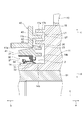
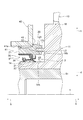
- FIG. 2 is a partial cross-sectional view taken along a line along an axis, for illustrating a schematic configuration of a sealing structure in a front cover of an engine as a resin cover according to the embodiment of the present invention.
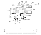
- FIG. 2 is a partially enlarged sectional view of the sealing structure shown in FIG. 1.
- FIG. 2 is a cross-sectional view schematically showing a structure of a single unit before being welded to a front cover of the sealing device shown in FIG.
- FIG. 4 is a partially enlarged cross-sectional view showing, in an enlarged manner, the vicinity of a joint portion of a support ring shown in FIG. It is sectional drawing which shows the modification of the labyrinth seal in the sealing structure in the engine front cover which concerns on embodiment of this invention.
- FIG. 1 is a partial cross-sectional view taken along a line along an axis, for illustrating a schematic configuration of a sealing structure in a front cover of an engine as a resin cover according to the embodiment of the present invention
- FIG. 10 is a cross-sectional view showing another modification of the labyrinth seal in the sealing structure of the front cover of the engine according to the embodiment of the present invention. It is sectional drawing which shows the modification of the sealing device in the sealing structure in the front cover of the engine which concerns on embodiment of this invention.
- FIG. 10 is a cross-sectional view showing another modification of the sealing device in the sealing structure of the front cover of the engine according to the embodiment of the present invention.
- FIG. 7 is a cross-sectional view showing a modification of a joint portion of a support ring in a sealing structure of a front cover of an engine according to an embodiment of the present invention.
- FIG. 1 is a cross-sectional view taken along an axis for illustrating a schematic configuration of a sealing structure (hereinafter, also simply referred to as a “sealing structure”) in an engine front cover as a resin cover according to an embodiment of the present invention.
- FIG. 2 is a partial sectional view, and FIG. 2 is a partially enlarged sectional view of the sealing structure shown in FIG.
- the direction of arrow a in the direction of the axis x is defined as the outside
- the direction of the arrow b in the direction of the axis x is defined as the inside.
- the outside is a direction away from the inside of the front cover
- the inside is a direction approaching the inside of the front cover.
- a direction perpendicular to the axis x hereinafter, also referred to as “radial direction”
- the direction away from the axis x is defined as the outer peripheral side
- the direction approaching the axis x is defined as the inner circumferential side.
- the sealing structure 1 in the front cover of the engine includes a resin engine front provided with a through hole 41 through which a shaft (a boss 14 of the torsion damper 10 described later) is inserted.
- a cover 40 and a sealing device 2 for sealing between the through hole 41 of the front cover 40 and the shaft portion are provided.
- the sealing device 2 includes an annular support ring 20 made of resin around the axis x, and an elastic body portion 30 formed of an annular elastic body around the axis x attached to the support ring 20.
- the elastic body portion 30 has an annular seal lip 31 with which the shaft portion slidably contacts the shaft portion, and the support ring 20 is joined to the front cover 40.
- the sealing structure 1 in the engine front cover includes a resin front cover, an torsion damper, and a torsion damper as a shaft portion of an engine used for a vehicle or a general-purpose machine.
- the present invention is applied to a sealing device for sealing an annular space between a boss portion and a through hole of a front cover.
- the damper pulley 10 as the torsional damper 10 is fixed to one end of a crankshaft 51 of the engine by a bolt 52.
- the damper pulley 10 includes a hub 11, a pulley 12 as a mass body, and a damper elastic body 13 disposed between the hub 11 and the pulley 12.
- the hub 11 is an annular member centered on the axis x, and has a boss 14 as an inner peripheral shaft, a rim 15 on the outer peripheral, and a substantially disk connecting the boss 14 and the rim 15. And a circular disk portion 16.
- the hub 11 is manufactured, for example, from a metal material by casting or the like.
- the boss portion 14 is an annular portion centered on the axis x where the through hole 14a is formed, and the disk portion 16 extends in the outer peripheral direction from the outer peripheral surface of the outer portion.
- the boss portion 14 has an outer peripheral surface 14b which is an outer peripheral surface of a cylindrical inner portion, and the outer peripheral surface 14b is a smooth surface.
- the rim portion 15 is an annular portion, more specifically, a cylindrical portion centered on the axis x, and is a portion located concentrically with the boss portion 14 and located on the outer peripheral side of the boss portion 14.
- a disk portion 16 extends in an inner circumferential direction from an inner circumferential surface 15a which is an inner circumferential surface of the rim portion 15.
- a damper elastic body 13 is crimped to an outer peripheral surface 15b which is an outer peripheral surface of the rim portion 15.
- the disk 16 extends between the boss 14 and the rim 15 and connects the boss 14 and the rim 15.
- the disk portion 16 may extend in a direction perpendicular to the axis x, or may extend in a direction inclined with respect to the axis x. Further, the disk portion 16 may have a curved cross section along the axis x (hereinafter, also simply referred to as a “cross section”) or may have a shape extending straight. Further, as shown in FIGS. 1 and 2, at least one window portion 16 a which is a through-hole penetrating the disk portion 16 between the inside and the outside is formed in the disk portion 16.
- four windows 16a are formed concentrically with respect to the axis x at equal angular intervals in the circumferential direction.
- the weight of the hub 11 and thus the damper pulley 10 is reduced by the window 16a.
- the damper pulley 10 does not need to have the window 16a.
- the pulley 12 is an annular member centered on the axis x, and has a shape that covers the hub 11 on the outer peripheral side.
- the inner peripheral surface 12a which is the inner peripheral surface of the pulley 12
- has a shape corresponding to the outer peripheral surface 15b of the rim portion 15 of the hub 11, and as shown in FIG. Are located such that the inner peripheral surface 12a thereof is opposed to the outer peripheral surface 15b of the rim portion 15 at an interval in the radial direction.
- a plurality of annular v-grooves 12c are formed on an outer peripheral surface 12b which is an outer peripheral surface of the pulley 12, so that a timing belt (not shown) can be wound.
- the damper elastic body 13 is provided between the pulley 12 and the rim 15 of the hub 11.
- the damper elastic body 13 is a damper rubber, and is formed by cross-linking a rubber-like elastic material having excellent heat resistance, cold resistance, and fatigue strength.
- the damper elastic body 13 is press-fitted between the pulley 12 and the rim portion 15 of the hub 11, and is fitted and fixed to the inner peripheral surface 12a of the pulley 12 and the outer peripheral surface 15b of the rim portion 15.
- the pulley 12 and the damper elastic body 13 form a damper portion, and the natural frequency of the damper portion in the torsional direction is a predetermined frequency range in which the torsion angle of the crankshaft 51 is maximized. Tuning is performed so as to match the natural frequency of the shaft 51 in the torsional direction. That is, the circumferential inertial mass of the pulley 12 and the torsional shear spring constant of the damper elastic body 13 are adjusted so that the natural frequency of the damper section in the torsional direction matches the natural frequency of the crankshaft 51 in the torsional direction. Have been.
- the damper pulley 10 has at least one torsion damper protrusion, which is an annular portion protruding in the direction of the axis x and forming a front cover 40 and a labyrinth seal L1 described later.
- the damper pulley 10 has two torsion damper protrusions (the outer protrusion 17a and the inner protrusion 17b).
- the outer peripheral side protruding portion 17a and the inner peripheral side protruding portion 17b are provided on an inner side surface 16b which is a disk-shaped surface facing inward on the inner peripheral side with respect to the window portion 16a of the disk portion 16 of the hub 11.
- annular portion protruding inward in the direction of the axis x from the inner side surface 16b and centered or substantially centered on the axis x.
- the outer peripheral side protruding portion 17a is provided on the outer peripheral side of the inner peripheral side protruding portion 17b, and a radial interval is constant or substantially constant between the outer peripheral side protruding portion 17a and the inner peripheral side protruding portion 17b.
- Hub groove 11b which is an annular groove centered or substantially centered on the axis x.
- the damper pulley 10 is attached to one end of the crankshaft 51 in the engine. Specifically, as shown in FIG. 1, one end of the crankshaft 51 is inserted into the through hole 14 a of the boss portion 14 of the hub 11, a bolt 52 is screwed into the crankshaft 51 from the outside, and the damper pulley 10 is It is fixed to the shaft 51.
- the damper pulley 10 When mounted on the crankshaft 51, the damper pulley 10 is configured such that an inner portion having the outer peripheral surface 14 b of the boss portion 14 is inserted into the through hole 41 of the front cover 40, An annular space (gap g1) is formed between the surface 14b and the through hole 41 of the front cover 40.
- the sealing device 2 has the support ring 20 made of resin and the elastic body portion 30 formed of an elastic body attached to the support ring 20. As shown in FIGS. 1 and 2, in the sealing structure 1, the sealing device 2 is joined to the front cover 40 at the support ring 20 by welding.
- FIG. 3 is a cross-sectional view of a cross-section along the axis x of the sealing device 2 schematically showing the configuration of the sealing device 2 itself before being welded to the front cover 40.
- the support ring 20 is an annular resin member centered or substantially centered on the axis x, and is an entrance portion which is an annular portion that enters the through hole 41 of the front cover 40. 21, a joining portion 22 which is an annular portion joined to the front cover 40 by welding, and an outer portion 23 which is an annular portion protruding outside the through hole 41 of the front cover 40.
- the support ring 20 is formed integrally from a resin material, and the entry portion 21, the joining portion 22, and the outer portion 23 are the respective portions of the support ring 20 formed integrally.
- the approach portion 21 extends along the axis x, and has an outer peripheral surface 21 a facing the outer peripheral side and an inner peripheral surface 21 b facing the inner peripheral side.
- the entry portion 21 is in the through hole 41 of the front cover 40, and the outer peripheral surface 21 a is used when the support ring 20 is attached to the front cover 40, for example.
- the shape is such that the entry portion 21 is guided into the through hole 41.
- the outer peripheral surface 21 a of the entry portion 21 is a tapered surface whose diameter decreases from the outside (the direction of the arrow a) to the inside (the direction of the arrow b) in the axis x direction.
- the diameter of the outer end (end 21 c) of the outer peripheral surface 21 a is the same or substantially the same as the diameter of the inner peripheral surface 41 a of the through hole 41 of the front cover 40. Thereby, the axial alignment between the through hole 41 of the front cover 40 and the sealing device 2 is facilitated.
- the joint portion 22 has an annular protrusion 22 a that is convex in the axis x direction.
- the support ring 20 is joined to the front cover 40 via a melted protrusion 22 a, and the protrusion 22 a of the joint portion 22 is a portion to be welded. is there.
- the joint portion 22 is provided with an annular concave portion 22b that is concave in the direction of the axis x on at least one of the inner peripheral side and the outer peripheral side of the protrusion 22a.
- one recess 22b is provided on the outer peripheral side of the protrusion 22a.
- the concave portion 22b forms a space into which the melted projection 22a flows when the support ring 20 is welded.
- FIG. 4 is a partially enlarged sectional view showing the vicinity of the joining portion 22 of the support ring 20 in an enlarged manner.
- the joining portion 22 has a joining surface 22c that is a surface facing inward in the direction of the annular axis x around the axis x.
- the concave portion 22b is concave outward from the joint surface 22c.
- the joining surface 22c is, for example, a plane orthogonal or substantially orthogonal to the axis x.
- the joint portion 22 may have a plurality of protrusions 22a arranged in the radial direction.
- the outer portion 23 of the support ring 20 is a portion that is connected to the entrance portion 21 on the outside, and is a portion where the joint portion 22 is formed. That is, the outer portion 23 protrudes to the outer peripheral side of the entrance portion 21.
- a welding jig guide portion 23a which is an annular concave portion concaved from the outside to the inside, is formed in the outer portion 23.
- the welding jig guide portion 23a is a portion to which a welding jig fits when the support ring 20 is welded to the front cover 40, as described later.
- the elastic body portion 30 is attached to the support ring 20, and is formed integrally with the support ring 20 so as to cover the inner peripheral side of the support ring 20 in the present embodiment.
- the elastic body portion 30 is attached to an inner peripheral surface 21 b of the entrance portion 21 of the support ring 20 and an annular convex portion 23 b protruding to the inner peripheral side of the outer portion 23.
- the elastic body portion 30 has the seal lip 31, and is provided outside the seal lip 31 (in the direction of the arrow a) and extends in the shape of an annular dust lip 32 extending toward the axis x. have. Further, the elastic body portion 30 has an annular lip waist portion 33.
- the seal lip 31 is formed such that the outer peripheral surface 14b slidably contacts the outer peripheral surface 14b of the boss portion 14 of the damper pulley 10 in the sealing structure 1.
- the dust lip 32 is provided outside the seal lip 31, and is formed such that the outer peripheral surface 14 b slidably contacts the outer peripheral surface 14 b of the boss 14 of the damper pulley 10.
- the lip waist portion 33 is a portion of the elastic body portion 30 that supports the seal lip 31 and the dust lip 32.
- the seal lip 31 is a portion that extends inward from the lip waist portion 33 and is an annular portion centered or substantially centered on the axis x. It is formed to face the part 21.
- the seal lip 31 has a wedge-shaped annular lip tip portion 34 whose cross-sectional shape is convex toward the inner peripheral side at an inner end portion.
- an annular concave portion 35 is formed at a position opposite to the lip tip portion 34, and a garter spring 36 is fitted into the concave portion 35.
- the garter spring 36 pushes the lip tip 34 in the direction toward the axis x so that the lip tip 34 follows the displacement of the boss 14 of the damper pulley 10 by a predetermined size relative to the boss 14. Gives the stress of being.
- the lip tip portion 34 comes into contact with the outer peripheral surface 14b of the boss portion 14 as described later to achieve sealing between the sealing device 2 and the boss portion 14.
- the dust strip 32 extends outward from the lip waist 33 toward the axis x, and specifically extends outward and inward from the lip waist 33 as shown in FIG.
- the dust lip 32 prevents foreign matters such as muddy water, sand, and dust from entering the lip tip portion 34 from the outside.
- the dust lip 32 may come close to the boss portion 14 of the damper pulley 10 without contacting the boss portion 14.
- the elastic portion 30 is integrally formed from an elastic material, and the seal lip 31, the dust lip 32, the lip waist portion 33, and other portions are the respective portions of the elastic portion 30 integrally formed from the elastic material. It is.
- the resin material of the support ring 20 is a resin that can be welded, for example, a thermoplastic resin, as described later.
- the resin material of the support ring 20 is a resin material that does not melt depending on the ambient temperature in the use state of the sealed structure 1, that is, the ambient temperature in the use state of the engine.
- the resin material of the support ring 20 is, for example, a hard thermoplastic synthetic resin material such as polyamide, polyester, polypropylene, and ABS resin.
- the resin material of the support ring 20 may be the same as the resin material of the front cover 40.
- examples of the elastic body of the elastic body section 30 include various rubber materials.
- the support ring 20 is manufactured by, for example, injection molding, and the elastic body portion 30 is formed by cross-linking (vulcanization) using a mold. At the time of this cross-linking molding, the support ring 20 is disposed in a molding die, the elastic body portion 30 is adhered to the support ring 20 by cross-linking adhesion, and the elastic body portion 30 is formed integrally with the support ring 20. You.
- the support ring 20 of the sealing device 2 has the entry portion 21 and the outer portion 23, is long in the axis x direction, and can cover the elastic body portion 30 on the inner peripheral side of the support ring 20. .
- the support ring 20 protects the elastic body portion 30 from the outside at the time of transporting the sealing device 2 in which the plurality of sealing devices 2 are stacked and transported in the direction of the axis x or at the time of assembling the sealing device 2.
- the front cover 40 is formed of a resin material as described above, and examples of the resin material include synthetic resins such as polyamide, polyester, polypropylene, and ABS resin. As shown in FIGS. 1 and 2, the front cover 40 has a through hole 41 through which the boss 14 of the crankshaft 51 and the damper pulley 10 is inserted. An annular gap g1 is formed between the inner peripheral surface 41a of the through hole 41 and the outer peripheral surface 14b of the boss portion 14, and the gap g1 is sealed by the sealing device 2 welded to the front cover 40. ing.
- the joining portion 22 of the support ring 20 is joined to the vicinity of the through hole 41 by welding on an outer surface 42 facing the outside of the front cover 40.
- the front cover 40 has a front cover projecting portion 43 which is an annular portion projecting from the outer surface 42 toward the disk portion 16 of the hub 11 of the damper pulley 10.
- the front cover projection 43 forms the above-described labyrinth seal L1 with the outer peripheral projection 17a and the inner peripheral projection 17b of the boss 14 of the damper pulley 10.
- the front cover protrusion 43 enters the hub groove 11b, which is an annular groove formed by the outer protrusion 17a and the inner protrusion 17b.
- the front cover protrusion 43 does not contact the hub groove 11b. For this reason, as shown in FIG. 2, an annular gap g2 having a U-shaped cross section is formed between the front cover protrusion 43 and the hub groove 11b, and between the front cover 40 and the damper pulley 10.
- a labyrinth seal L1 is formed. From the viewpoint of improving the sealing property of the labyrinth seal L1, the gap g2 between the front cover projection 43 and the hub groove 11b is preferably narrow.
- a method of joining the support ring 20 of the sealing device 2 to the front cover 40 will be described.
- a jig (not shown) is attached to the welding jig guide portion 23a of the sealing device 2 before joining shown in FIG. 3, the sealing device 2 is grasped by the jig, and the entry portion 21 of the support ring 20 is inserted into the through hole 41 of the front cover 40. It is inserted so that the projection 22 a of the joint portion 22 of the support ring 20 is in contact with the outer surface 42 of the front cover 40.
- the protrusion 22a of the joint portion 22 is vibrated while being pressed against the outer surface 42 of the front cover 40 to melt the protrusion 22a, and the support ring 20 is joined to the joint cover 22 by the melted protrusion 22a. Is welded to the outer surface 42.
- the means for vibrating the projection 22a for welding may be the above-described jig for gripping the sealing device 2 or may generate another vibration, and may be irradiated with ultrasonic waves or laser light. Or other means.
- an annular concave portion 22 b is formed in the joint portion 22, and when the support ring 20 is welded, a part of the molten protrusion that is not used for welding with the front cover 40. 22a flows into the recess 22b. For this reason, the joining state between the support ring 20 and the front cover 40 can be improved, and the formation of a welding beam can be suppressed or prevented.
- the concave portion 22b is located on the outer peripheral side of the projection 22a in the joint portion 22, but the concave portion 22b may be located on the inner peripheral side of the projection 22a.
- the recess 22b may be formed.
- the concave portion 22b may be formed on the outer peripheral side and the inner peripheral side of the protrusion 22a.
- a welding jig guide portion 23 a to which a jig is attached is formed on the support ring 20 of the sealing device 2, so that the efficiency of the operation of attaching the sealing device 2 to the front cover 40 can be improved.
- the resin support ring 20 is joined to the resin front cover 40 by welding. And, by this joining, the space between the sealing device 2 and the front cover 40 is sealed. Therefore, the difference in the coefficient of thermal expansion between the sealed portions of the support ring 20 and the front cover 40 can be reduced, and the joining state between the support ring 20 and the front cover 40 can be stabilized. The sealed state between the sealing device 2 and the front cover 40 can be stably maintained.
- the resin material of the support ring 20 and the resin material of the front cover 40 have a small difference in coefficient of thermal expansion.
- the relative position between the support ring 20 and the boss portion 14 of the damper pulley 10 may change due to a difference in thermal expansion coefficient. Or the gap between the dust lip 32 and the outer peripheral surface 14b of the boss portion 14 may be widened, so that foreign matter may easily enter the seal lip 31 side.
- the sealing structure 1 has the labyrinth seal L1 on the upstream side of the dust lip 32 in the foreign matter entry path, and the labyrinth seal L1 blocks entry of the foreign matter. For this reason, as described above, even if the dust lip 32 becomes in a state where foreign matter easily enters the seal lip 31 side due to thermal expansion, the labyrinth seal L1 can prevent foreign matter from entering, and the dust lip 32 can be prevented. Function can be supplemented. Further, the labyrinth seal L1 can further prevent foreign substances from entering.
- the sealing structure 1 in the engine front cover according to the embodiment of the present invention can maintain the sealing performance irrespective of the state of use.
- the present invention is not limited to the above-described embodiments of the present invention, but includes all aspects included in the concept of the present invention and the claims.
- the components may be appropriately selectively combined so as to achieve at least a part of the above-described problems and effects.
- the shape, material, arrangement, size, manufacturing method, and the like of each component in the above embodiment can be appropriately changed depending on the specific usage of the present invention.
- the form of the labyrinth seal upstream of the dust lip 32 in the foreign matter entry path in the present invention is not limited to the above-mentioned labyrinth seal L1, and may be another form.
- the labyrinth seal L1 is formed by inserting the front cover protrusion 43 into the hub groove 11b formed by the outer protrusion 17a and the inner protrusion 17b, but one protrusion and one protrusion are formed.
- a labyrinth seal may be formed by a gap formed by facing each other.
- the damper pulley 10 has only one of the outer peripheral side protruding portion 17a and the inner peripheral side protruding portion 17b, and the labyrinth seal L1 is connected to either the outer peripheral side protruding portion 17a or the inner peripheral side protruding portion 17b. It may be formed by the front cover protrusion 43.
- the front cover 40 has two front cover protrusions 43, and these two front cover protrusions 43 are the same as the outer peripheral side protrusion 17a and the inner peripheral side protrusion 17b.
- An annular groove may be formed in the groove, and the outer peripheral side projection 17a or the inner peripheral side projection 17b may enter the groove to form the labyrinth seal L1.
- the damper pulley 10 may have only one of the outer peripheral side protruding portion 17a and the inner peripheral side protruding portion 17b.
- the front cover 40 has a plurality of front cover protrusions 43
- the damper pulley 10 has a plurality of torsion damper protrusions (outer periphery protrusion 17a or inner periphery protrusion 17b).
- the labyrinth seal L1 may be formed by a gap between the plurality of protrusions.
- the supporting ring 20 may form a labyrinth seal with the damper pulley 10 instead of, or together with, the labyrinth seal L1 described above.
- a labyrinth seal L2 may be provided between the support ring 20 and the damper pulley 10.
- an annular projection 17c that enters the welding jig guide 23a of the outer portion 23 of the support ring 20, and between the projection 17c and the welding jig guide 23a.
- a labyrinth seal L2 may be formed between the support ring 20 and the damper pulley 10 by forming an annular gap g3 having a U-shaped cross section.
- the labyrinth seal L2 between the support ring 20 and the damper pulley 10 may have another form.
- the labyrinth seal L2 may be formed by forming an annular gap in which the protruding portion 17c faces the outer peripheral surface or the inner peripheral surface of the outer portion 23 of the support ring 20 from the outer peripheral side or the inner peripheral side.
- the damper pulley 10 may have the hub groove 11b instead of the protrusion 17c, and the support ring 20 may have an annular protrusion that enters the hub groove 11b and forms the labyrinth seal L2.
- the support ring 20 is joined to the front cover 40 by welding, but the support ring 20 may be joined to the front cover 40 by an adhesive.
- the support ring 20 does not have to have the protrusion 22a and the recess 22b in the joint portion 22, but has only the joint surface 22c.
- the joint 22 may have a recess 22b as a space for the adhesive to escape.
- the support ring in the sealing device of the present invention is not limited to the above-described support ring 20, and may have any other shape as long as the elastic body portion 30 is attached and can be joined to the front cover 40.
- the sealing device may be a modified example as shown in FIGS.
- the sealing device 3 according to the first modification has a support ring 24 different from the support ring 20 of the sealing device 2, and the support ring 24 has an entry portion 21. Absent.
- the sealing device 4 according to the second modified example has a supporting ring 25 different from the supporting ring 20 of the sealing device 2, and the supporting ring 25 is No part 23 is provided.
- the portion where the support ring 20 is welded to the front cover 40 is not limited to the above-described portion (joining portion 22).
- the joint portion 22 may be located at another support ring 20, and the support ring 20 may have a plurality of joint portions 22.
- the support ring 20 may have a joining portion 22 also on the inner side surface 21 d of the entry portion 21. In this case, a portion where the joining portion 22 of the entry portion 21 is welded to the front cover 40 is provided.
- the resin cover of the present invention is not limited to the engine front cover and may be made of another resin. Cover.
- the present invention can be applied to a sealing structure between a shaft portion that moves, such as a rotary motion and a reciprocating motion, and a resin cover, and the resin cover of the present invention
- the cover may be a resin cover for a machine, a resin cover for a differential mechanism of an automobile or the like, a resin cover for a steering mechanism, a resin cover for a motor, a resin cover for a reduction gear, or the like.
- a shaft portion that moves such as a rotary motion and a reciprocating motion, and a resin cover having a space through which the shaft portion is inserted The present invention can be applied.
- SYMBOLS 1 Sealing structure in engine front cover, 2, 3, 4 ... Sealing device, 10 ... Torsion damper (damper pulley), 11 ... Hub, 11b ... Hub groove, 12 ... Pulley, 12a ... Inner peripheral surface, 12b ... Outer periphery Surface, 12c: v-groove, 13: damper elastic body, 14: boss, 14a: through hole, 14b: outer peripheral surface, 15: rim, 15a: inner peripheral surface, 15b: outer peripheral surface, 16: disk portion, 16a ... Window, 16b ... Inner side, 17a ... Outer side protruding part, 17b ... Inner side protruding part, 17c ...
Abstract
Provided is a sealing structure for a resin cover, configured so that sealing properties can be maintained irrespective of the state of use. A sealing structure (1) for a front cover for an engine is provided with: a resin front cover (40) for an engine, which is provided with a through-hole (41) into which a boss (14) of a torsional damper (10) is inserted; and a sealing device (2) for sealing between the through-hole (41) in the front cover (40) and a shaft section. The sealing device (2) is provided with an annular resin support ring (20) and an elastic body section (30) which is formed from an annular elastic body and which is mounted to the support ring (20). The elastic body section (30) has an annular seal lip (31) coming into slidable contact with the shaft section. The support ring (20) is joined to the front cover (40).
Description
本発明は、樹脂製カバーにおける密封構造に関し、特に樹脂製のエンジンのフロントカバー等における運動部材との間の密封装置を用いた密封構造に関する。
The present invention relates to a sealing structure in a resin cover, and more particularly to a sealing structure using a sealing device between a moving member in a front cover and the like of a resin engine.
例えば車両のエンジンにおいて、クランケース側面に取り付けられた補器やタイミングチェーンを覆うエンジンのフロントカバーには貫通孔が設けられており、この貫通孔を通ってクランクシャフトの端部が外部に飛び出しており、この端部にトーショナルダンパが取り付けられている。フロントカバーの貫通孔において、この貫通孔とクランクシャフトの端部又はトーショナルダンパのボス部との間には環状の空間が形成され、この空間を密封するために密封装置としてのオイルシールが用いられている。オイルシールは、フロントカバーの貫通孔に圧入されて、外周側のゴム材が圧縮されることによりフロントカバーに固定されている(例えば、特許文献1参照)。
For example, in the engine of a vehicle, a through hole is provided in the front cover of the engine that covers the accessories and the timing chain attached to the side of the clan case, and the end of the crankshaft protrudes outside through this through hole. The torsion damper is attached to this end. In the through hole of the front cover, an annular space is formed between the through hole and the end of the crankshaft or the boss of the torsional damper, and an oil seal as a sealing device is used to seal this space. Have been. The oil seal is fixed to the front cover by being pressed into a through hole of the front cover and compressing a rubber material on an outer peripheral side (for example, see Patent Document 1).
近年、車両の燃費向上等の理由から、車両の軽量化が図られており、エンジンも軽量化が図られており、エンジンのフロントカバーに対しても軽量化は求められている。従来のエンジンのフロントカバーは、アルミニウム合金等の金属製であったが、軽量化のため、エンジンのフロントカバーの樹脂化が検討されてきている。
In recent years, the weight of vehicles has been reduced for reasons such as improvement of fuel efficiency of vehicles, and the weight of engines has also been reduced. The weight of front covers of engines has also been required to be reduced. Conventionally, a front cover of an engine is made of a metal such as an aluminum alloy. However, in order to reduce the weight, resinization of the front cover of the engine has been studied.
樹脂の成形品は、寸法公差が大きく、また、樹脂は熱膨張率やクリープ変形量が大きい。このため、エンジンにおいて樹脂製のフロントカバーを用いた場合、貫通孔に圧入されるオイルシールとフロントカバーとの間に隙間が形成される懸念がある。特に、オイルシールのゴム材とフロントカバーの樹脂材との間の熱膨張率の差により、フロントカバーが熱膨張した際に、フロントカバーの貫通孔の内周面とオイルシールの外周面との間に隙間が形成されるおそれがある。
Resin molded products have large dimensional tolerances, and resins have large coefficients of thermal expansion and creep deformation. For this reason, when a resin front cover is used in the engine, there is a concern that a gap may be formed between the oil seal press-fit into the through hole and the front cover. In particular, due to the difference in the coefficient of thermal expansion between the rubber material of the oil seal and the resin material of the front cover, when the front cover thermally expands, the gap between the inner peripheral surface of the through hole of the front cover and the outer peripheral surface of the oil seal is increased. A gap may be formed between them.
このように、樹脂製のエンジンのフロントカバー等の樹脂製のカバーにおける密封構造に対しては、周辺温度等の使用状態に拘わらず密封性能を維持することができる構成が求められていた。
As described above, for a sealing structure of a resin cover such as a front cover of a resin engine, a configuration capable of maintaining the sealing performance irrespective of a use condition such as an ambient temperature has been required.
本発明は、上述の課題に鑑みてなされたものであり、その目的は、使用状態に拘わらず密封性能を維持することができる樹脂製のカバーにおける密封構造を提供することにある。
The present invention has been made in view of the above-described problems, and an object of the present invention is to provide a sealing structure in a resin cover that can maintain sealing performance regardless of a use state.
上記目的を達成するために、本発明に係る樹脂製のカバーにおける密封構造は、軸部が挿通される貫通孔が設けられた樹脂製のカバーと、前記樹脂製のカバーの貫通孔と前記軸部との間の密封を図るための密封装置とを備え、前記密封装置は、軸線周りに環状の樹脂製の支持環と、前記支持環に取り付けられている前記軸線周りに環状の弾性体から形成された弾性体部とを備え、前記弾性体部は、前記軸部に該軸部が摺動可能に接触する環状のシールリップを有しており、前記支持環は、前記樹脂製のカバーに接合されていることを特徴とする。
In order to achieve the above object, the sealing structure in the resin cover according to the present invention includes a resin cover provided with a through hole through which a shaft portion is inserted, a through hole of the resin cover, and the shaft. And a sealing device for sealing between the parts, the sealing device comprises a ring-shaped resin support ring around an axis, and a ring-shaped elastic body around the axis attached to the support ring. An elastic member formed, wherein the elastic member has an annular seal lip with which the shaft is slidably contacted with the shaft, and the support ring is formed of the resin cover. It is characterized by being joined to.
本発明の一態様に係る樹脂製のカバーにおける密封構造において、前記支持環は、前記樹脂製のカバーに溶着によって接合されている。
In the sealing structure of the resin cover according to one aspect of the present invention, the support ring is joined to the resin cover by welding.
本発明の一態様に係る樹脂製のカバーにおける密封構造において、前記支持環の前記樹脂製のカバーに接合される部分である接合部分は、前記軸線周りに環状であり、前記接合部分は、前記軸線方向に凸の環状の突起部を有しており、前記支持環は、溶かされた前記突起部を介して前記樹脂製のカバーに接合されている。
In the sealing structure of the resin cover according to one embodiment of the present invention, a joining portion of the support ring, which is a portion joined to the resin cover, is annular around the axis, and the joining portion is The support ring has an annular protrusion that is convex in the axial direction, and the support ring is joined to the resin cover via the melted protrusion.
本発明の一態様に係る樹脂製のカバーにおける密封構造において、前記支持環には、前記突起部の内周側及び外周側の少なくともいずれかに、前記軸線方向に凹む環状の凹部が設けられている。
In the sealing structure of the resin cover according to one aspect of the present invention, the support ring is provided with an annular concave portion that is concave in the axial direction on at least one of an inner peripheral side and an outer peripheral side of the protrusion. I have.
本発明の一態様に係る樹脂製のカバーにおける密封構造において、前記支持環は、前記樹脂製のカバーに接着剤によって接合されている。
In the sealing structure of the resin cover according to one embodiment of the present invention, the support ring is joined to the resin cover with an adhesive.
本発明の一態様に係る樹脂製のカバーにおける密封構造において、前記軸部は、トーショナルダンパのボス部であり、前記弾性体は、環状のダストリップを有しており、前記支持環は、前記トーショナルダンパとラビリンスシールを形成している。
In the sealing structure of the resin cover according to one embodiment of the present invention, the shaft portion is a boss portion of a torsional damper, the elastic body has an annular dust lip, the support ring, A labyrinth seal is formed with the torsion damper.
本発明の一態様に係る樹脂製のカバーにおける密封構造において、前記支持環は、前記軸線方向に突出する環状の部分である支持環突出部を少なくとも1つ有しており、前記トーショナルダンパは、前記軸線方向に突出する環状の部分であるトーショナルダンパ突出部を少なくとも1つ有しており、前記支持環突出部及び前記トーショナルダンパ突出部は、互いに対向して、環状の隙間を形成して前記ラビリンスシールを形成している。
In the sealing structure of the resin cover according to one embodiment of the present invention, the support ring has at least one support ring protrusion that is an annular portion that protrudes in the axial direction, and the torsion damper is And at least one torsion damper protrusion, which is an annular portion protruding in the axial direction, wherein the support ring protrusion and the torsion damper protrusion oppose each other to form an annular gap. Thus, the labyrinth seal is formed.
本発明の一態様に係る樹脂製のカバーにおける密封構造において、前記軸部は、トーショナルダンパのボス部であり、前記弾性体は、環状のダストリップを有しており、前記樹脂製のカバーは、前記トーショナルダンパとラビリンスシールを形成している。
In the sealing structure of the resin cover according to one embodiment of the present invention, the shaft portion is a boss portion of a torsional damper, and the elastic body has an annular dust lip, and the resin cover Form a labyrinth seal with the torsion damper.
本発明の一態様に係る樹脂製のカバーにおける密封構造において、前記樹脂製のカバーは、前記軸線方向に突出する環状の部分であるカバー突出部を少なくとも1つ有しており、前記トーショナルダンパは、前記軸線方向に突出する環状の部分であるトーショナルダンパ突出部を少なくとも1つ有しており、前記カバー突出部及び前記トーショナルダンパ突出部は、互いに対向して、環状の隙間を形成して前記ラビリンスシールを形成している。
In the sealing structure of the resin cover according to one embodiment of the present invention, the resin cover has at least one cover protrusion that is an annular portion that protrudes in the axial direction, and the torsion damper Has at least one torsion damper protrusion, which is an annular portion protruding in the axial direction, and the cover protrusion and the torsion damper protrusion oppose each other to form an annular gap. Thus, the labyrinth seal is formed.
本発明に係る樹脂製のカバーにおける密封構造によれば、使用状態に拘わらず密封性能を維持することができる。
According to the sealing structure of the resin cover according to the present invention, the sealing performance can be maintained regardless of the use condition.
以下、本発明の実施の形態について図面を参照しながら説明する。
Hereinafter, embodiments of the present invention will be described with reference to the drawings.
図1は、本発明の実施の形態に係る樹脂製のカバーとしてのエンジンのフロントカバーにおける密封構造(以下、単に「密封構造」ともいう。)の概略構成を示すための、軸線に沿う断面における部分断面図であり、図2は、図1に示す密封構造の部分拡大断面図である。以下、説明の便宜上、軸線x方向において矢印a(図1参照)方向を外側とし、軸線x方向において矢印b(図1参照)方向を内側とする。より具体的には、外側とは、フロントカバーの内部から離れる方向であり、内側とは、フロントカバーの内部に近づく方向である。また、軸線xに垂直な方向(以下、「径方向」ともいう。)において、軸線xから離れる方向(図1の矢印c方向)を外周側とし、軸線xに近づく方向(図1の矢印d方向)を内周側とする。
FIG. 1 is a cross-sectional view taken along an axis for illustrating a schematic configuration of a sealing structure (hereinafter, also simply referred to as a “sealing structure”) in an engine front cover as a resin cover according to an embodiment of the present invention. FIG. 2 is a partial sectional view, and FIG. 2 is a partially enlarged sectional view of the sealing structure shown in FIG. Hereinafter, for convenience of explanation, the direction of arrow a (see FIG. 1) in the direction of the axis x is defined as the outside, and the direction of the arrow b (see FIG. 1) in the direction of the axis x is defined as the inside. More specifically, the outside is a direction away from the inside of the front cover, and the inside is a direction approaching the inside of the front cover. In a direction perpendicular to the axis x (hereinafter, also referred to as “radial direction”), the direction away from the axis x (the direction of arrow c in FIG. 1) is defined as the outer peripheral side, and the direction approaching the axis x (arrow d in FIG. 1). Direction) is the inner circumferential side.
図1,2に示すように、エンジンのフロントカバーにおける密封構造1は、軸部(後述するトーショナルダンパ10のボス部14)が挿通される貫通孔41が設けられた樹脂製のエンジンのフロントカバー40と、フロントカバー40の貫通孔41と軸部との間の密封を図るための密封装置2とを備えている。密封装置2は、軸線x周りに環状の樹脂製の支持環20と、支持環20に取り付けられている軸線x周りに環状の弾性体から形成された弾性体部30とを備えている。弾性体部30は、軸部にこの軸部が摺動可能に接触する環状のシールリップ31を有しており、支持環20は、フロントカバー40に接合されている。以下、本発明の実施の形態に係るエンジンのフロントカバーにおける密封構造1について具体的に説明する。
As shown in FIGS. 1 and 2, the sealing structure 1 in the front cover of the engine includes a resin engine front provided with a through hole 41 through which a shaft (a boss 14 of the torsion damper 10 described later) is inserted. A cover 40 and a sealing device 2 for sealing between the through hole 41 of the front cover 40 and the shaft portion are provided. The sealing device 2 includes an annular support ring 20 made of resin around the axis x, and an elastic body portion 30 formed of an annular elastic body around the axis x attached to the support ring 20. The elastic body portion 30 has an annular seal lip 31 with which the shaft portion slidably contacts the shaft portion, and the support ring 20 is joined to the front cover 40. Hereinafter, the sealing structure 1 in the engine front cover according to the embodiment of the present invention will be specifically described.
なお、本発明の実施の形態に係るエンジンのフロントカバーにおける密封構造1は、車両や汎用機械等に用いられるエンジンの樹脂製のフロントカバーと、トーショナルダンパと、軸部としてのトーショナルダンパのボス部とフロントカバーの貫通孔との間の環状の空間を密封する密封装置に適用されるものである。
In addition, the sealing structure 1 in the engine front cover according to the embodiment of the present invention includes a resin front cover, an torsion damper, and a torsion damper as a shaft portion of an engine used for a vehicle or a general-purpose machine. The present invention is applied to a sealing device for sealing an annular space between a boss portion and a through hole of a front cover.
トーショナルダンパ10としてのダンパプーリ10は、エンジンのクランクシャフト51の一端にボルト52によって固定されている。ダンパプーリ10は、ハブ11と、質量体としてのプーリ12と、ハブ11とプーリ12との間に配設されたダンパ弾性体13とを備えている。ハブ11は、軸線xを中心とする環状の部材であり、内周側の軸部としてのボス部14と、外周側のリム部15と、ボス部14とリム部15とを接続する略円盤状の円盤部16とを備えている。ハブ11は、例えば、金属材料から鋳造等によって製造されている。
The damper pulley 10 as the torsional damper 10 is fixed to one end of a crankshaft 51 of the engine by a bolt 52. The damper pulley 10 includes a hub 11, a pulley 12 as a mass body, and a damper elastic body 13 disposed between the hub 11 and the pulley 12. The hub 11 is an annular member centered on the axis x, and has a boss 14 as an inner peripheral shaft, a rim 15 on the outer peripheral, and a substantially disk connecting the boss 14 and the rim 15. And a circular disk portion 16. The hub 11 is manufactured, for example, from a metal material by casting or the like.
ハブ11において、ボス部14は、貫通孔14aが形成された軸線xを中心とする環状の部分であり、外側の部分の外周面から外周方向に円盤部16が延びている。ボス部14は、円筒状の内側の部分の外周側の面である外周面14bを備えており、外周面14bは滑らかな面となっており、後述するように、密封装置2のシール面となっている。リム部15は、軸線xを中心とする環状の、より具体的には円筒状の部分であり、ボス部14に対して同心的にボス部14よりも外周側に位置する部分である。リム部15の内周側の面である内周面15aからは円盤部16が内周方向に延びている。リム部15の外周側の面である外周面15bにはダンパ弾性体13が圧着されている。
In the hub 11, the boss portion 14 is an annular portion centered on the axis x where the through hole 14a is formed, and the disk portion 16 extends in the outer peripheral direction from the outer peripheral surface of the outer portion. The boss portion 14 has an outer peripheral surface 14b which is an outer peripheral surface of a cylindrical inner portion, and the outer peripheral surface 14b is a smooth surface. Has become. The rim portion 15 is an annular portion, more specifically, a cylindrical portion centered on the axis x, and is a portion located concentrically with the boss portion 14 and located on the outer peripheral side of the boss portion 14. A disk portion 16 extends in an inner circumferential direction from an inner circumferential surface 15a which is an inner circumferential surface of the rim portion 15. A damper elastic body 13 is crimped to an outer peripheral surface 15b which is an outer peripheral surface of the rim portion 15.
円盤部16は、ボス部14とリム部15との間に延びて、ボス部14とリム部15とを接続している。円盤部16は、軸線xに対して垂直な方向に延びていてもよく、軸線xに対して傾斜する方向に延びていてもよい。また、円盤部16は、軸線xに沿う断面(以下、単に「断面」ともいう。)が湾曲した形状であっても、真っ直ぐに延びる形状であってもよい。また、図1,2に示すように、円盤部16には、円盤部16を内側と外側との間で貫通する貫通穴である窓部16aが少なくとも1つ形成されており、本実施の形態においては、4つの窓部16aが軸線xに対して同心的に周方向に等角度間隔で形成されている。この窓部16aによって、ハブ11、ひいてはダンパプーリ10の軽量化が図られている。なお、ダンパプーリ10は、窓部16aを有していなくてもよい。
The disk 16 extends between the boss 14 and the rim 15 and connects the boss 14 and the rim 15. The disk portion 16 may extend in a direction perpendicular to the axis x, or may extend in a direction inclined with respect to the axis x. Further, the disk portion 16 may have a curved cross section along the axis x (hereinafter, also simply referred to as a “cross section”) or may have a shape extending straight. Further, as shown in FIGS. 1 and 2, at least one window portion 16 a which is a through-hole penetrating the disk portion 16 between the inside and the outside is formed in the disk portion 16. In, four windows 16a are formed concentrically with respect to the axis x at equal angular intervals in the circumferential direction. The weight of the hub 11 and thus the damper pulley 10 is reduced by the window 16a. In addition, the damper pulley 10 does not need to have the window 16a.
プーリ12は、軸線xを中心とする環状の部材であり、ハブ11を外周側において覆うような形状を呈している。具体的には、プーリ12の内周側の面である内周面12aは、ハブ11のリム部15の外周面15bに対応した形状を有しており、図1に示すように、プーリ12は、その内周面12aがリム部15の外周面15bに径方向において間隔を空けて対向するように位置している。また、プーリ12の外周側の面である外周面12bには、環状のv溝12cが複数形成されており、図示しないタイミングベルトが巻回可能になっている。
The pulley 12 is an annular member centered on the axis x, and has a shape that covers the hub 11 on the outer peripheral side. Specifically, the inner peripheral surface 12a, which is the inner peripheral surface of the pulley 12, has a shape corresponding to the outer peripheral surface 15b of the rim portion 15 of the hub 11, and as shown in FIG. Are located such that the inner peripheral surface 12a thereof is opposed to the outer peripheral surface 15b of the rim portion 15 at an interval in the radial direction. A plurality of annular v-grooves 12c are formed on an outer peripheral surface 12b which is an outer peripheral surface of the pulley 12, so that a timing belt (not shown) can be wound.
ダンパ弾性体13は、プーリ12とハブ11のリム部15との間に設けられている。ダンパ弾性体13は、ダンパゴムであり、耐熱性、耐寒性、及び疲労強度において優れたゴム状弾性材料から架橋成形されて形成されている。ダンパ弾性体13は、プーリ12とハブ11のリム部15との間に圧入されており、プーリ12の内周面12aとリム部15の外周面15bとに嵌着されて固定されている。
The damper elastic body 13 is provided between the pulley 12 and the rim 15 of the hub 11. The damper elastic body 13 is a damper rubber, and is formed by cross-linking a rubber-like elastic material having excellent heat resistance, cold resistance, and fatigue strength. The damper elastic body 13 is press-fitted between the pulley 12 and the rim portion 15 of the hub 11, and is fitted and fixed to the inner peripheral surface 12a of the pulley 12 and the outer peripheral surface 15b of the rim portion 15.
ダンパプーリ10において、プーリ12とダンパ弾性体13とがダンパ部を形成しており、ダンパ部の捩り方向固有振動数が、クランクシャフト51の捩れ角が最大となる所定の振動数域である、クランクシャフト51の捩り方向固有振動数と一致するように同調されている。つまり、ダンパ部の捩り方向固有振動数がクランクシャフト51の捩り方向固有振動数と一致するように、プーリ12の円周方向の慣性質量と、ダンパ弾性体13の捩り方向剪断ばね定数とが調整されている。
In the damper pulley 10, the pulley 12 and the damper elastic body 13 form a damper portion, and the natural frequency of the damper portion in the torsional direction is a predetermined frequency range in which the torsion angle of the crankshaft 51 is maximized. Tuning is performed so as to match the natural frequency of the shaft 51 in the torsional direction. That is, the circumferential inertial mass of the pulley 12 and the torsional shear spring constant of the damper elastic body 13 are adjusted so that the natural frequency of the damper section in the torsional direction matches the natural frequency of the crankshaft 51 in the torsional direction. Have been.
また、ダンパプーリ10は、フロントカバー40と後述するラビリンスシールL1を形成する、軸線x方向に突出する環状の部分であるトーショナルダンパ突出部を少なくとも1つ有している。本実施の形態においては、ダンパプーリ10は、トーショナルダンパ突出部を2つ(外周側突出部17a、内周側突出部17b)有している。外周側突出部17a及び内周側突出部17bは、ハブ11の円盤部16の窓部16aよりも内周側において内側に面する円盤状の面である内側面16bに設けられており、この内側面16bから軸線x方向において内側に向かって突出している、軸線xを中心又は略中心とする環状の部分である。外周側突出部17aは、内周側突出部17bよりも外周側に設けられており、外周側突出部17aと内周側突出部17bとの間には、径方向の間隔が一定又は略一定の軸線xを中心又は略中心とする環状の溝であるハブ溝11bが形成されている。
The damper pulley 10 has at least one torsion damper protrusion, which is an annular portion protruding in the direction of the axis x and forming a front cover 40 and a labyrinth seal L1 described later. In the present embodiment, the damper pulley 10 has two torsion damper protrusions (the outer protrusion 17a and the inner protrusion 17b). The outer peripheral side protruding portion 17a and the inner peripheral side protruding portion 17b are provided on an inner side surface 16b which is a disk-shaped surface facing inward on the inner peripheral side with respect to the window portion 16a of the disk portion 16 of the hub 11. An annular portion protruding inward in the direction of the axis x from the inner side surface 16b and centered or substantially centered on the axis x. The outer peripheral side protruding portion 17a is provided on the outer peripheral side of the inner peripheral side protruding portion 17b, and a radial interval is constant or substantially constant between the outer peripheral side protruding portion 17a and the inner peripheral side protruding portion 17b. Hub groove 11b, which is an annular groove centered or substantially centered on the axis x.
上述のように、ダンパプーリ10は、エンジンにおいてクランクシャフト51の一端に取り付けられている。具体的には、図1に示すように、クランクシャフト51の一端がハブ11のボス部14の貫通孔14aに挿通され、外側からボルト52がクランクシャフト51に螺合されて、ダンパプーリ10がクランクシャフト51に固定されている。
As described above, the damper pulley 10 is attached to one end of the crankshaft 51 in the engine. Specifically, as shown in FIG. 1, one end of the crankshaft 51 is inserted into the through hole 14 a of the boss portion 14 of the hub 11, a bolt 52 is screwed into the crankshaft 51 from the outside, and the damper pulley 10 is It is fixed to the shaft 51.
クランクシャフト51に取り付けられた状態において、ダンパプーリ10は、ボス部14の外周面14bを有する内側の部分がフロントカバー40の貫通孔41内に挿通された状態になっており、ボス部14の外周面14bと、フロントカバー40の貫通孔41との間に環状の空間(隙間g1)が形成されている。
When mounted on the crankshaft 51, the damper pulley 10 is configured such that an inner portion having the outer peripheral surface 14 b of the boss portion 14 is inserted into the through hole 41 of the front cover 40, An annular space (gap g1) is formed between the surface 14b and the through hole 41 of the front cover 40.
密封装置2は、上述のように、樹脂製の支持環20と、支持環20に取り付けられた弾性体から形成された弾性体部30とを有している。図1,2に示すように、密封構造1において、密封装置2は、支持環20においてフロントカバー40に溶着によって接合されている。図3は、フロントカバー40に溶着される前の密封装置2単体の構成を概略的に示す密封装置2の軸線xに沿う断面における断面図である。
As described above, the sealing device 2 has the support ring 20 made of resin and the elastic body portion 30 formed of an elastic body attached to the support ring 20. As shown in FIGS. 1 and 2, in the sealing structure 1, the sealing device 2 is joined to the front cover 40 at the support ring 20 by welding. FIG. 3 is a cross-sectional view of a cross-section along the axis x of the sealing device 2 schematically showing the configuration of the sealing device 2 itself before being welded to the front cover 40.
図1~3に示すように、支持環20は、軸線xを中心又は略中心とする環状の樹脂製の部材であり、フロントカバー40の貫通孔41内に進入する環状の部分である進入部21と、フロントカバー40に溶着によって接合される環状の部分である接合部分22と、フロントカバー40の貫通孔41の外側に突出する環状の部分である外側部23とを有している。支持環20は、樹脂材から一体的に形成されており、進入部21、接合部分22、及び外側部23は一体に形成された支持環20の各部分である。
As shown in FIGS. 1 to 3, the support ring 20 is an annular resin member centered or substantially centered on the axis x, and is an entrance portion which is an annular portion that enters the through hole 41 of the front cover 40. 21, a joining portion 22 which is an annular portion joined to the front cover 40 by welding, and an outer portion 23 which is an annular portion protruding outside the through hole 41 of the front cover 40. The support ring 20 is formed integrally from a resin material, and the entry portion 21, the joining portion 22, and the outer portion 23 are the respective portions of the support ring 20 formed integrally.
図3に示すように、進入部21は、軸線xに沿って延びており、外周側に面する外周面21aと、内周側に面する内周面21bとを有している。図1,2に示すように、密封構造1において、進入部21は、フロントカバー40の貫通孔41内に入っており、外周面21aは、例えば、支持環20をフロントカバー40に取り付ける際に進入部21を貫通孔41内に案内するような形状となっている。具体的には、図3に示すように、進入部21の外周面21aは、軸線x方向において外側(矢印a方向側)から内側(矢印b方向側)に向かって縮径するテーパ面となっている。また、外周面21aの外側の端部(端部21c)の径は、フロントカバー40の貫通孔41の内周面41aの径と同じ又は略同じとなっている。これにより、フロントカバー40の貫通孔41と密封装置2との軸合わせが容易になっている。
進 As shown in FIG. 3, the approach portion 21 extends along the axis x, and has an outer peripheral surface 21 a facing the outer peripheral side and an inner peripheral surface 21 b facing the inner peripheral side. As shown in FIGS. 1 and 2, in the sealing structure 1, the entry portion 21 is in the through hole 41 of the front cover 40, and the outer peripheral surface 21 a is used when the support ring 20 is attached to the front cover 40, for example. The shape is such that the entry portion 21 is guided into the through hole 41. Specifically, as shown in FIG. 3, the outer peripheral surface 21 a of the entry portion 21 is a tapered surface whose diameter decreases from the outside (the direction of the arrow a) to the inside (the direction of the arrow b) in the axis x direction. ing. The diameter of the outer end (end 21 c) of the outer peripheral surface 21 a is the same or substantially the same as the diameter of the inner peripheral surface 41 a of the through hole 41 of the front cover 40. Thereby, the axial alignment between the through hole 41 of the front cover 40 and the sealing device 2 is facilitated.
接合部分22は、図3,4に示すように、軸線x方向に凸の環状の突起部22aを有している。図1,2に示すように、密封構造1において支持環20は、溶かされた突起部22aを介してフロントカバー40に接合されており、接合部分22の突起部22aは、溶着される部分である。また、接合部分22には、突起部22aの内周側及び外周側の少なくともいずれかに、軸線x方向に凹む環状の凹部22bが設けられている。本実施の形態においては、1つの凹部22bが突起部22aの外周側に設けられている。凹部22bは、支持環20の溶着の際に、溶けた突起部22aが流れ入るための空間を形成している。なお、図4は、支持環20の接合部分22近傍を拡大して示す部分拡大断面図である。
(3) As shown in FIGS. 3 and 4, the joint portion 22 has an annular protrusion 22 a that is convex in the axis x direction. As shown in FIGS. 1 and 2, in the sealing structure 1, the support ring 20 is joined to the front cover 40 via a melted protrusion 22 a, and the protrusion 22 a of the joint portion 22 is a portion to be welded. is there. In addition, the joint portion 22 is provided with an annular concave portion 22b that is concave in the direction of the axis x on at least one of the inner peripheral side and the outer peripheral side of the protrusion 22a. In the present embodiment, one recess 22b is provided on the outer peripheral side of the protrusion 22a. The concave portion 22b forms a space into which the melted projection 22a flows when the support ring 20 is welded. FIG. 4 is a partially enlarged sectional view showing the vicinity of the joining portion 22 of the support ring 20 in an enlarged manner.
具体的には、接合部分22は、図3,4に示すように、軸線x周りに環状の軸線x方向において内側に面する面である接合面22cを有しており、突起部22aは、接合面22cから内側に向かって凸であり、凹部22bは接合面22cから外側に向かって凹んでいる。接合面22cは、例えば、軸線xに直交する又は略直交する平面である。なお、接合部分22は、突起部22aを径方向に並んで複数有していてもよい。
Specifically, as shown in FIGS. 3 and 4, the joining portion 22 has a joining surface 22c that is a surface facing inward in the direction of the annular axis x around the axis x. The concave portion 22b is concave outward from the joint surface 22c. The joining surface 22c is, for example, a plane orthogonal or substantially orthogonal to the axis x. Note that the joint portion 22 may have a plurality of protrusions 22a arranged in the radial direction.
また、支持環20の外側部23は、図3に示すように、進入部21に外側においてつながる部分であり、接合部分22が形成されている部分である。つまり、外側部23は、進入部21よりも外周側に出っ張っている。また、外側部23には、外側から内側に向かって凹む環状の凹部である溶着冶具ガイド部23aが形成されている。溶着冶具ガイド部23aは、後述するように、支持環20をフロントカバー40に溶着する際に、溶着冶具が嵌る部分である。
Further, as shown in FIG. 3, the outer portion 23 of the support ring 20 is a portion that is connected to the entrance portion 21 on the outside, and is a portion where the joint portion 22 is formed. That is, the outer portion 23 protrudes to the outer peripheral side of the entrance portion 21. Further, a welding jig guide portion 23a, which is an annular concave portion concaved from the outside to the inside, is formed in the outer portion 23. The welding jig guide portion 23a is a portion to which a welding jig fits when the support ring 20 is welded to the front cover 40, as described later.
弾性体部30は、図3に示すように、支持環20に取り付けられており、本実施の形態においては支持環20の内周側を覆うように支持環20と一体的に形成されている。例えば、図3に示すように、弾性体部30は、支持環20の進入部21の内周面21b、及び外側部23の内周側に突出する環状の凸部23bに取り付けられている。弾性体部30は、上述のように、シールリップ31を有しており、また、シールリップ31よりも外側(矢印a方向側)に設けられており軸線xに向かって延びる環状のダストリップ32を有している。また、弾性体部30は、環状のリップ腰部33を有している。シールリップ31は、密封構造1においてダンパプーリ10のボス部14の外周面14bにこの外周面14bが摺動可能に接触するように形成されている。ダストリップ32は、シールリップ31よりも外側に設けられており、ダンパプーリ10のボス部14の外周面14bにこの外周面14bが摺動可能に接触するように形成されている。リップ腰部33は、弾性体部30において、シールリップ31及びダストリップ32を支持する部分である。
As shown in FIG. 3, the elastic body portion 30 is attached to the support ring 20, and is formed integrally with the support ring 20 so as to cover the inner peripheral side of the support ring 20 in the present embodiment. . For example, as shown in FIG. 3, the elastic body portion 30 is attached to an inner peripheral surface 21 b of the entrance portion 21 of the support ring 20 and an annular convex portion 23 b protruding to the inner peripheral side of the outer portion 23. As described above, the elastic body portion 30 has the seal lip 31, and is provided outside the seal lip 31 (in the direction of the arrow a) and extends in the shape of an annular dust lip 32 extending toward the axis x. have. Further, the elastic body portion 30 has an annular lip waist portion 33. The seal lip 31 is formed such that the outer peripheral surface 14b slidably contacts the outer peripheral surface 14b of the boss portion 14 of the damper pulley 10 in the sealing structure 1. The dust lip 32 is provided outside the seal lip 31, and is formed such that the outer peripheral surface 14 b slidably contacts the outer peripheral surface 14 b of the boss 14 of the damper pulley 10. The lip waist portion 33 is a portion of the elastic body portion 30 that supports the seal lip 31 and the dust lip 32.
シールリップ31は、具体的には、図3に示すように、リップ腰部33から内側に向かって延びる部分であり、軸線xを中心又は略中心とする環状の部分であり、支持環20の進入部21に対向して形成されている。シールリップ31は、内側の端部に、断面形状が内周側に向かって凸の楔形状の環状のリップ先端部34を有している。また、シールリップ31の外周側には、リップ先端部34に背向する位置に環状の凹部35が形成されており、この凹部35にガータスプリング36が嵌着されている。ガータスプリング36は、リップ先端部34を軸線xに向かう方向に押して、リップ先端部34がダンパプーリ10のボス部14の変位に対して追随するようにリップ先端部34にボス部14に対する所定の大きさの緊迫力を与える。リップ先端部34は、後述するようにボス部14の外周面14bに接触して、密封装置2とボス部14との間の密封を図る。
Specifically, as shown in FIG. 3, the seal lip 31 is a portion that extends inward from the lip waist portion 33 and is an annular portion centered or substantially centered on the axis x. It is formed to face the part 21. The seal lip 31 has a wedge-shaped annular lip tip portion 34 whose cross-sectional shape is convex toward the inner peripheral side at an inner end portion. On the outer peripheral side of the seal lip 31, an annular concave portion 35 is formed at a position opposite to the lip tip portion 34, and a garter spring 36 is fitted into the concave portion 35. The garter spring 36 pushes the lip tip 34 in the direction toward the axis x so that the lip tip 34 follows the displacement of the boss 14 of the damper pulley 10 by a predetermined size relative to the boss 14. Gives the stress of being. The lip tip portion 34 comes into contact with the outer peripheral surface 14b of the boss portion 14 as described later to achieve sealing between the sealing device 2 and the boss portion 14.
ダストリップ32は、リップ腰部33から外側に軸線xに向かって延びており、具体的には、図3に示すように、リップ腰部33から外側且つ内周側の方向に延出している。ダストリップ32により、外側からリップ先端部34方向への、泥水や砂、ダスト等の異物の侵入の防止が図られている。ダストリップ32は、ダンパプーリ10のボス部14に接触せずに近接するようになっていてもよい。
The dust strip 32 extends outward from the lip waist 33 toward the axis x, and specifically extends outward and inward from the lip waist 33 as shown in FIG. The dust lip 32 prevents foreign matters such as muddy water, sand, and dust from entering the lip tip portion 34 from the outside. The dust lip 32 may come close to the boss portion 14 of the damper pulley 10 without contacting the boss portion 14.
なお、弾性体部30は弾性材から一体に形成されており、シールリップ31、ダストリップ32、リップ腰部33、及び他の部分は、弾性材から一体に形成された弾性体部30の各部分である。
The elastic portion 30 is integrally formed from an elastic material, and the seal lip 31, the dust lip 32, the lip waist portion 33, and other portions are the respective portions of the elastic portion 30 integrally formed from the elastic material. It is.
支持環20の樹脂材は、後述するように、溶着が可能な樹脂であり、例えば、熱可塑性の樹脂である。但し、支持環20の樹脂材は、密封構造1の使用状態の雰囲気温度によって、つまり、エンジンの使用状態の雰囲気温度によって溶けない樹脂材である。支持環20の樹脂材は、例えば、ポリアミド、ポリエステル、ポリプロピレン、ABS樹脂等の硬質の熱可塑性合成樹脂材である。支持環20の樹脂材は、フロントカバー40の樹脂材と同じであってもよい。また、弾性体部30の弾性体としては、例えば、各種ゴム材がある。各種ゴム材としては、例えば、ニトリルゴム(NBR)、水素添加ニトリルゴム(H-NBR)、アクリルゴム(ACM)、フッ素ゴム(FKM)等の合成ゴムである。支持環20は、例えば射出成形によって製造され、弾性体部30は成形型を用いて架橋(加硫)成形によって成形される。この架橋成形の際に、支持環20は成形型の中に配置されており、弾性体部30が架橋接着により支持環20に接着され、弾性体部30が支持環20と一体的に成形される。
樹脂 The resin material of the support ring 20 is a resin that can be welded, for example, a thermoplastic resin, as described later. However, the resin material of the support ring 20 is a resin material that does not melt depending on the ambient temperature in the use state of the sealed structure 1, that is, the ambient temperature in the use state of the engine. The resin material of the support ring 20 is, for example, a hard thermoplastic synthetic resin material such as polyamide, polyester, polypropylene, and ABS resin. The resin material of the support ring 20 may be the same as the resin material of the front cover 40. Further, examples of the elastic body of the elastic body section 30 include various rubber materials. Examples of the various rubber materials include synthetic rubbers such as nitrile rubber (NBR), hydrogenated nitrile rubber (H-NBR), acrylic rubber (ACM), and fluoro rubber (FKM). The support ring 20 is manufactured by, for example, injection molding, and the elastic body portion 30 is formed by cross-linking (vulcanization) using a mold. At the time of this cross-linking molding, the support ring 20 is disposed in a molding die, the elastic body portion 30 is adhered to the support ring 20 by cross-linking adhesion, and the elastic body portion 30 is formed integrally with the support ring 20. You.
密封装置2の支持環20は、上述のように、進入部21及び外側部23を有しており、軸線x方向に長く、弾性体部30を支持環20の内周側に覆うことができる。このため、支持環20は、複数の密封装置2が軸線x方向に積み重ねられて搬送される密封装置2の輸送時や、密封装置2の組み付け時等において弾性体部30を外部から保護することができる。この点において、径方向外周側から密封装置2を見た際に、弾性体部30は支持環20に隠れる位置に設けられていることが好ましい。
As described above, the support ring 20 of the sealing device 2 has the entry portion 21 and the outer portion 23, is long in the axis x direction, and can cover the elastic body portion 30 on the inner peripheral side of the support ring 20. . For this reason, the support ring 20 protects the elastic body portion 30 from the outside at the time of transporting the sealing device 2 in which the plurality of sealing devices 2 are stacked and transported in the direction of the axis x or at the time of assembling the sealing device 2. Can be. In this regard, it is preferable that the elastic body portion 30 be provided at a position that is hidden by the support ring 20 when the sealing device 2 is viewed from the radially outer peripheral side.
フロントカバー40は、上述のように、樹脂材から形成されており、樹脂材としては、例えば、ポリアミド、ポリエステル、ポリプロピレン、ABS樹脂等の合成樹脂がある。フロントカバー40は、図1,2に示すように、クランクシャフト51及びダンパプーリ10のボス部14が挿通される貫通孔41が形成されている。貫通孔41の内周面41aとボス部14の外周面14bとの間には、環状の隙間g1が形成されており、この隙間g1は、フロントカバー40に溶着された密封装置2によって密閉されている。
(4) The front cover 40 is formed of a resin material as described above, and examples of the resin material include synthetic resins such as polyamide, polyester, polypropylene, and ABS resin. As shown in FIGS. 1 and 2, the front cover 40 has a through hole 41 through which the boss 14 of the crankshaft 51 and the damper pulley 10 is inserted. An annular gap g1 is formed between the inner peripheral surface 41a of the through hole 41 and the outer peripheral surface 14b of the boss portion 14, and the gap g1 is sealed by the sealing device 2 welded to the front cover 40. ing.
図2に示すように、密封構造1において支持環20の接合部分22は、フロントカバー40の外側に面する外側面42において、貫通孔41の近傍に溶着により接合されている。また、フロントカバー40は、外側面42からダンパプーリ10のハブ11の円盤部16に向かって突出する環状の部分であるフロントカバー突出部43を有している。フロントカバー突出部43は、上述のラビリンスシールL1をダンパプーリ10のボス部14の外周側突出部17a及び内周側突出部17bと形成している。具体的には、図2に示すように、密封構造1において、フロントカバー突出部43は、外周側突出部17a及び内周側突出部17bが形成する環状の溝であるハブ溝11b内に入り込んでいる。フロントカバー突出部43は、ハブ溝11bに接触していない。このため、図2に示すように、フロントカバー突出部43とハブ溝11bとの間に断面がコの字状の環状の隙間g2が形成されており、フロントカバー40とダンパプーリ10との間にラビリンスシールL1が形成されている。ラビリンスシールL1のシール性の向上の観点から、フロントカバー突出部43とハブ溝11bとの間の隙間g2は、狭い方がよい。
As shown in FIG. 2, in the sealing structure 1, the joining portion 22 of the support ring 20 is joined to the vicinity of the through hole 41 by welding on an outer surface 42 facing the outside of the front cover 40. Further, the front cover 40 has a front cover projecting portion 43 which is an annular portion projecting from the outer surface 42 toward the disk portion 16 of the hub 11 of the damper pulley 10. The front cover projection 43 forms the above-described labyrinth seal L1 with the outer peripheral projection 17a and the inner peripheral projection 17b of the boss 14 of the damper pulley 10. Specifically, as shown in FIG. 2, in the sealing structure 1, the front cover protrusion 43 enters the hub groove 11b, which is an annular groove formed by the outer protrusion 17a and the inner protrusion 17b. In. The front cover protrusion 43 does not contact the hub groove 11b. For this reason, as shown in FIG. 2, an annular gap g2 having a U-shaped cross section is formed between the front cover protrusion 43 and the hub groove 11b, and between the front cover 40 and the damper pulley 10. A labyrinth seal L1 is formed. From the viewpoint of improving the sealing property of the labyrinth seal L1, the gap g2 between the front cover projection 43 and the hub groove 11b is preferably narrow.
次いで、フロントカバー40への密封装置2の支持環20の接合方法について説明する。先ず、図3に示す接合前の密封装置2の溶着冶具ガイド部23aに図示しない冶具を取り付け、密封装置2を冶具により掴み、支持環20の進入部21をフロントカバー40の貫通孔41内に挿入し、支持環20の接合部分22の突起部22aがフロントカバー40の外側面42に当接した状態にする。そして、接合部分22の突起部22aをフロントカバー40の外側面42に圧接させながら振動させ、突起部22aを溶融させ、この溶融させた突起部22aによって接合部分22において支持環20をフロントカバー40の外側面42に溶着させる。溶着のために突起部22aを振動させる手段は、上述の密封装置2の掴み用の冶具であってもよく、他の振動を発生するものであってもよく、超音波やレーザー光の照射であってもよく、他の手段であってもよい。
Next, a method of joining the support ring 20 of the sealing device 2 to the front cover 40 will be described. First, a jig (not shown) is attached to the welding jig guide portion 23a of the sealing device 2 before joining shown in FIG. 3, the sealing device 2 is grasped by the jig, and the entry portion 21 of the support ring 20 is inserted into the through hole 41 of the front cover 40. It is inserted so that the projection 22 a of the joint portion 22 of the support ring 20 is in contact with the outer surface 42 of the front cover 40. Then, the protrusion 22a of the joint portion 22 is vibrated while being pressed against the outer surface 42 of the front cover 40 to melt the protrusion 22a, and the support ring 20 is joined to the joint cover 22 by the melted protrusion 22a. Is welded to the outer surface 42. The means for vibrating the projection 22a for welding may be the above-described jig for gripping the sealing device 2 or may generate another vibration, and may be irradiated with ultrasonic waves or laser light. Or other means.
図3,4に示すように、接合部分22には環状の凹部22bが形成されており、支持環20の溶着の際に、フロントカバー40との溶着に使われない一部の溶融した突起部22aが凹部22bに流れ込む。このため、支持環20とフロントカバー40との間の接合状態を良好にすることができ、また、溶着ばりの形成を抑制又は防止することができる。なお、図示の例においては、接合部分22において凹部22bは突起部22aの外周側に位置しているが、凹部22bは突起部22aの内周側に位置していてもよく、また、複数の凹部22bが形成されていてもよい。凹部22bは、突起部22aの外周側及び内周側に形成されていてもよい。
As shown in FIGS. 3 and 4, an annular concave portion 22 b is formed in the joint portion 22, and when the support ring 20 is welded, a part of the molten protrusion that is not used for welding with the front cover 40. 22a flows into the recess 22b. For this reason, the joining state between the support ring 20 and the front cover 40 can be improved, and the formation of a welding beam can be suppressed or prevented. In the illustrated example, the concave portion 22b is located on the outer peripheral side of the projection 22a in the joint portion 22, but the concave portion 22b may be located on the inner peripheral side of the projection 22a. The recess 22b may be formed. The concave portion 22b may be formed on the outer peripheral side and the inner peripheral side of the protrusion 22a.
密封装置2の支持環20には、冶具が取り付けられる溶着冶具ガイド部23aが形成されており、密封装置2のフロントカバー40への取付作業の効率を向上させることができる。
溶 A welding jig guide portion 23 a to which a jig is attached is formed on the support ring 20 of the sealing device 2, so that the efficiency of the operation of attaching the sealing device 2 to the front cover 40 can be improved.
次いで、上述の構成を有する密封構造1の作用について説明する。
Next, the operation of the sealing structure 1 having the above configuration will be described.
上述のように、密封装置2は、その樹脂製の支持環20が溶着によって樹脂製のフロントカバー40に接合されている。そして、この接合によって、密封装置2とフロントカバー40との間が密封されている。このため、支持環20及びフロントカバー40の密封部位間の熱膨張率の差を低減することができ、支持環20とフロントカバー40との間の接合状態を安定したものにすることができ、密封装置2とフロントカバー40との間の密封状態を安定して保持できる。このように、密封構造1においては、支持環20とフロントカバー40との間に隙間が形成されることがなく、使用状態に応じた密封性能の低下を防止することができる。このため、支持環20の樹脂材及びフロントカバー40の樹脂材は、互いの熱膨張率の差が小さくなるものが好ましい。
As described above, in the sealing device 2, the resin support ring 20 is joined to the resin front cover 40 by welding. And, by this joining, the space between the sealing device 2 and the front cover 40 is sealed. Therefore, the difference in the coefficient of thermal expansion between the sealed portions of the support ring 20 and the front cover 40 can be reduced, and the joining state between the support ring 20 and the front cover 40 can be stabilized. The sealed state between the sealing device 2 and the front cover 40 can be stably maintained. Thus, in the sealing structure 1, no gap is formed between the support ring 20 and the front cover 40, and it is possible to prevent a decrease in sealing performance according to a use state. For this reason, it is preferable that the resin material of the support ring 20 and the resin material of the front cover 40 have a small difference in coefficient of thermal expansion.
また、支持環20とダンパプーリ10のボス部14との間においては、熱膨張率の違いにより相対位置が変化することがあり、このため、雰囲気温度の状態によっては、ダストリップ32がボス部14の外周面14bから離れ、または、ダストリップ32とボス部14の外周面14bとの間の間隔が広がり、異物がシールリップ31側に入りやすくなる状態となる場合がある。しかしながら、密封構造1は、異物の侵入経路においてダストリップ32の位置よりも上流側にラビリンスシールL1を有しており、このラビリンスシールL1によって異物の侵入が遮られている。このため、上述のように、熱膨張により異物がシールリップ31側に入りやすくなる状態にダストリップ32がなったとしても、ラビリンスシールL1によって異物の侵入の防止を図ることができ、ダストリップ32の機能を補うことができる。また、ラビリンスシールL1により、異物の侵入の防止をより図ることができる。
Further, the relative position between the support ring 20 and the boss portion 14 of the damper pulley 10 may change due to a difference in thermal expansion coefficient. Or the gap between the dust lip 32 and the outer peripheral surface 14b of the boss portion 14 may be widened, so that foreign matter may easily enter the seal lip 31 side. However, the sealing structure 1 has the labyrinth seal L1 on the upstream side of the dust lip 32 in the foreign matter entry path, and the labyrinth seal L1 blocks entry of the foreign matter. For this reason, as described above, even if the dust lip 32 becomes in a state where foreign matter easily enters the seal lip 31 side due to thermal expansion, the labyrinth seal L1 can prevent foreign matter from entering, and the dust lip 32 can be prevented. Function can be supplemented. Further, the labyrinth seal L1 can further prevent foreign substances from entering.
このように、本発明の実施の形態に係るエンジンのフロントカバーにおける密封構造1は、その使用状態に拘わらず密封性能を維持することができる。
As described above, the sealing structure 1 in the engine front cover according to the embodiment of the present invention can maintain the sealing performance irrespective of the state of use.
以上、本発明の実施の形態について説明したが、本発明は上記本発明の実施の形態に限定されるものではなく、本発明の概念及び請求の範囲に含まれるあらゆる態様を含む。また、上述した課題及び効果の少なくとも一部を奏するように、各構成を適宜選択的に組み合わせてもよい。例えば、上記実施の形態における、各構成要素の形状、材料、配置、サイズ、製造法等は、本発明の具体的使用態様によって適宜変更され得る。
Although the embodiments of the present invention have been described above, the present invention is not limited to the above-described embodiments of the present invention, but includes all aspects included in the concept of the present invention and the claims. In addition, the components may be appropriately selectively combined so as to achieve at least a part of the above-described problems and effects. For example, the shape, material, arrangement, size, manufacturing method, and the like of each component in the above embodiment can be appropriately changed depending on the specific usage of the present invention.
例えば本発明における異物の侵入経路においてダストリップ32の位置よりも上流側のラビリンスシールの形態は、上述のラビリンスシールL1に限られず、他の形態であってもよい。例えば、ラビリンスシールL1は、外周側突出部17aと内周側突出部17bとが形成するハブ溝11bにフロントカバー突出部43が入り込んで形成されているが、1つの突起と1つの突起とが対向することにより形成される隙間によってラビリンスシールが形成されていてもよい。具体的には、ダンパプーリ10は、外周側突出部17a及び内周側突出部17bの一方のみを有しており、ラビリンスシールL1は、外周側突出部17aと内周側突出部17bのいずれかとフロントカバー突出部43とによって形成されていてもよい。
For example, the form of the labyrinth seal upstream of the dust lip 32 in the foreign matter entry path in the present invention is not limited to the above-mentioned labyrinth seal L1, and may be another form. For example, the labyrinth seal L1 is formed by inserting the front cover protrusion 43 into the hub groove 11b formed by the outer protrusion 17a and the inner protrusion 17b, but one protrusion and one protrusion are formed. A labyrinth seal may be formed by a gap formed by facing each other. Specifically, the damper pulley 10 has only one of the outer peripheral side protruding portion 17a and the inner peripheral side protruding portion 17b, and the labyrinth seal L1 is connected to either the outer peripheral side protruding portion 17a or the inner peripheral side protruding portion 17b. It may be formed by the front cover protrusion 43.
また、図5に示すように、フロントカバー40が2つのフロントカバー突出部43を有しており、この2つのフロントカバー突出部43が、外周側突出部17a及び内周側突出部17bと同様に環状の溝を形成しており、この溝内に外周側突出部17a又は内周側突出部17bが入り込んでラビリンスシールL1を形成していてもよい。この場合、ダンパプーリ10は、外周側突出部17a及び内周側突出部17bの一方のみを有していてもよい。また、フロントカバー40が複数のフロントカバー突出部43を有しており、ダンパプーリ10が複数のトーショナルダンパ突出部(外周側突出部17a又は内周側突出部17b)を有しており、これら複数の突出部の間の隙間によってラビリンスシールL1を形成していてもよい。
As shown in FIG. 5, the front cover 40 has two front cover protrusions 43, and these two front cover protrusions 43 are the same as the outer peripheral side protrusion 17a and the inner peripheral side protrusion 17b. An annular groove may be formed in the groove, and the outer peripheral side projection 17a or the inner peripheral side projection 17b may enter the groove to form the labyrinth seal L1. In this case, the damper pulley 10 may have only one of the outer peripheral side protruding portion 17a and the inner peripheral side protruding portion 17b. Further, the front cover 40 has a plurality of front cover protrusions 43, and the damper pulley 10 has a plurality of torsion damper protrusions (outer periphery protrusion 17a or inner periphery protrusion 17b). The labyrinth seal L1 may be formed by a gap between the plurality of protrusions.
また、上述のラビリンスシールL1に変えて、または、このラビリンスシールL1と共に、支持環20がダンパプーリ10とラビリンスシールを形成していてもよい。例えば、図6に示すように、支持環20とダンパプーリ10との間にラビリンスシールL2が設けられていてもよい。例えば、ダンパプーリ10の円盤部16の内側面16bに、支持環20の外側部23の溶着冶具ガイド部23aに入り込む環状の突出部17cを設け、突出部17cと溶着冶具ガイド部23aとの間に断面がコの字状の環状の隙間g3を形成して、支持環20とダンパプーリ10との間にラビリンスシールL2を形成してもよい。支持環20とダンパプーリ10との間のラビリンスシールL2は、他の形態であってもよい。例えば、突出部17cが外周側から又は内周側から支持環20の外側部23の外周面又は内周面に対向して環状の隙間を作ることにより、ラビリンスシールL2が形成されていてもよく、また、ダンパプーリ10が突出部17cではなくハブ溝11bを有しており、このハブ溝11b内に入り込んでラビリンスシールL2を形成する環状の突出部を支持環20が有していてもよい。
The supporting ring 20 may form a labyrinth seal with the damper pulley 10 instead of, or together with, the labyrinth seal L1 described above. For example, as shown in FIG. 6, a labyrinth seal L2 may be provided between the support ring 20 and the damper pulley 10. For example, on the inner surface 16b of the disk portion 16 of the damper pulley 10, there is provided an annular projection 17c that enters the welding jig guide 23a of the outer portion 23 of the support ring 20, and between the projection 17c and the welding jig guide 23a. A labyrinth seal L2 may be formed between the support ring 20 and the damper pulley 10 by forming an annular gap g3 having a U-shaped cross section. The labyrinth seal L2 between the support ring 20 and the damper pulley 10 may have another form. For example, the labyrinth seal L2 may be formed by forming an annular gap in which the protruding portion 17c faces the outer peripheral surface or the inner peripheral surface of the outer portion 23 of the support ring 20 from the outer peripheral side or the inner peripheral side. Further, the damper pulley 10 may have the hub groove 11b instead of the protrusion 17c, and the support ring 20 may have an annular protrusion that enters the hub groove 11b and forms the labyrinth seal L2.
上述の密封構造1においては、フロントカバー40に支持環20が溶着によって接合されていたが、支持環20はフロントカバー40に接着剤によって接合されていてもよい。この場合、支持環20は、接合部分22に突起部22a及び凹部22bを有していなくてもよく、接合面22cのみを有している。接着剤の逃げ空間として、接合部分22は凹部22bを有していてもよい。
In the sealing structure 1 described above, the support ring 20 is joined to the front cover 40 by welding, but the support ring 20 may be joined to the front cover 40 by an adhesive. In this case, the support ring 20 does not have to have the protrusion 22a and the recess 22b in the joint portion 22, but has only the joint surface 22c. The joint 22 may have a recess 22b as a space for the adhesive to escape.
また、本発明の密封装置における支持環は、上述の支持環20に限られず、弾性体部30が取り付けられ、フロントカバー40に接合可能な形状であれば他の形状であってもよい。例えば、密封装置は、図7,8に示すような変形例であってもよい。図7に示すように、第1の変形例に係る密封装置3は、密封装置2の支持環20とは異なる支持環24を有しており、支持環24は、進入部21を有していない。また、図8に示すように、第2の変形例に係る密封装置4は、密封装置2の支持環20とは異なる支持環25を有しており、支持環25は、進入部21及び外側部23を有していない。
The support ring in the sealing device of the present invention is not limited to the above-described support ring 20, and may have any other shape as long as the elastic body portion 30 is attached and can be joined to the front cover 40. For example, the sealing device may be a modified example as shown in FIGS. As shown in FIG. 7, the sealing device 3 according to the first modification has a support ring 24 different from the support ring 20 of the sealing device 2, and the support ring 24 has an entry portion 21. Absent. As shown in FIG. 8, the sealing device 4 according to the second modified example has a supporting ring 25 different from the supporting ring 20 of the sealing device 2, and the supporting ring 25 is No part 23 is provided.
また、支持環20がフロントカバー40に溶着される部位は、上述の部位(接合部分22)に限られない。例えば、接合部分22は他の支持環20の位置であってもよく、また、支持環20は複数の接合部分22を有していてもよい。例えば、図9に示すように、支持環20は、進入部21の内側面21dにも接合部分22を有していてもよい。この場合、フロントカバー40に進入部21の接合部分22が溶着される部分が設けられる。
部位 The portion where the support ring 20 is welded to the front cover 40 is not limited to the above-described portion (joining portion 22). For example, the joint portion 22 may be located at another support ring 20, and the support ring 20 may have a plurality of joint portions 22. For example, as shown in FIG. 9, the support ring 20 may have a joining portion 22 also on the inner side surface 21 d of the entry portion 21. In this case, a portion where the joining portion 22 of the entry portion 21 is welded to the front cover 40 is provided.
また、上記実施の形態おいては、エンジンのフロントカバーにおける密封構造に本発明が適用される場合を例示したが、本発明の樹脂製のカバーは、エンジンのフロントカバーに限られず他の樹脂製のカバーであってもよい。本発明は、回転運動や往復運動等の運動する軸部と樹脂製のカバーとの間の密封構造に対して適用することができ、本発明の樹脂製のカバーは、例えば、自動車等の変速機における樹脂製のカバー、自動車等のディファレンシャル機構における樹脂製のカバー、ステアリング機構における樹脂製のカバー、モータにおける樹脂製のカバー、減速機における樹脂製のカバー等であってもよい。回転運動や往復運動等の運動する軸部と、この軸部が挿通される空間を有する樹脂製のカバーとにおいて、この軸部とこの樹脂製のカバーとの間の隙間を密封するために、本発明を適用することができる。
Further, in the above-described embodiment, the case where the present invention is applied to the sealing structure in the engine front cover is illustrated. However, the resin cover of the present invention is not limited to the engine front cover and may be made of another resin. Cover. The present invention can be applied to a sealing structure between a shaft portion that moves, such as a rotary motion and a reciprocating motion, and a resin cover, and the resin cover of the present invention The cover may be a resin cover for a machine, a resin cover for a differential mechanism of an automobile or the like, a resin cover for a steering mechanism, a resin cover for a motor, a resin cover for a reduction gear, or the like. In order to seal a gap between the shaft portion and the resin cover, a shaft portion that moves such as a rotary motion and a reciprocating motion, and a resin cover having a space through which the shaft portion is inserted, The present invention can be applied.
1…エンジンのフロントカバーにおける密封構造、2,3,4…密封装置、10…トーショナルダンパ(ダンパプーリ)、11…ハブ、11b…ハブ溝、12…プーリ、12a…内周面、12b…外周面、12c…v溝、13…ダンパ弾性体、14…ボス部、14a…貫通孔、14b…外周面、15…リム部、15a…内周面、15b…外周面、16…円盤部、16a…窓部、16b…内側面、17a…外周側突出部、17b…内周側突出部、17c…突出部、20,24,25…支持環、21…進入部、21a…外周面、21b…内周面、21c…端部、21d…内側面、22…接合部分、22a…突起部、22b…凹部、22c…接合面、23…外側部、23a…溶着冶具ガイド部、23b…凸部、30…弾性体部、31…シールリップ、32…ダストリップ、33…リップ腰部、34…リップ先端部、35…凹部、36…ガータスプリング、40…エンジンのフロントカバー、41…貫通孔、41a…内周面、42…外側面、43…フロントカバー突出部、51…クランクシャフト、52…ボルト、g1,g2,g3…隙間、L1,L2…ラビリンスシール
DESCRIPTION OF SYMBOLS 1 ... Sealing structure in engine front cover, 2, 3, 4 ... Sealing device, 10 ... Torsion damper (damper pulley), 11 ... Hub, 11b ... Hub groove, 12 ... Pulley, 12a ... Inner peripheral surface, 12b ... Outer periphery Surface, 12c: v-groove, 13: damper elastic body, 14: boss, 14a: through hole, 14b: outer peripheral surface, 15: rim, 15a: inner peripheral surface, 15b: outer peripheral surface, 16: disk portion, 16a ... Window, 16b ... Inner side, 17a ... Outer side protruding part, 17b ... Inner side protruding part, 17c ... Protruding part, 20, 24, 25 ... Support ring, 21 ... Entry part, 21a ... Outer side, 21b ... Inner peripheral surface, 21c end, 21d inner surface, 22 joining part, 22a protrusion, 22b recess, 22c joining surface, 23 outer part, 23a welding jig guide, 23b convex 30 ... elastic body part, 31 ... seal lip 32 ... dust lip, 33 ... lip waist, 34 ... lip tip, 35 ... concave, 36 ... garter spring, 40 ... engine front cover, 41 ... through hole, 41a ... inner peripheral surface, 42 ... outer surface, 43 ... Projection of front cover, 51: crankshaft, 52: bolt, g1, g2, g3: gap, L1, L2: labyrinth seal
Claims (9)
- 樹脂製のカバーにおける密封構造であって、
軸部が挿通される貫通孔が設けられた樹脂製のカバーと、
前記樹脂製のカバーの貫通孔と前記軸部との間の密封を図るための密封装置とを備え、
前記密封装置は、軸線周りに環状の樹脂製の支持環と、前記支持環に取り付けられている前記軸線周りに環状の弾性体から形成された弾性体部とを備え、
前記弾性体部は、前記軸部に該軸部が摺動可能に接触する環状のシールリップを有しており、
前記支持環は、前記樹脂製のカバーに接合されていることを特徴とする樹脂製のカバーにおける密封構造。 A sealing structure in a resin cover,
A resin cover provided with a through hole through which the shaft portion is inserted,
A sealing device for sealing between the through hole of the resin cover and the shaft portion,
The sealing device includes an annular resin support ring around an axis, and an elastic body portion formed from an annular elastic body around the axis attached to the support ring.
The elastic body portion has an annular seal lip in which the shaft portion slidably contacts the shaft portion,
The sealing structure of the resin cover, wherein the support ring is joined to the resin cover. - 前記支持環は、前記樹脂製のカバーに溶着によって接合されていることを特徴とする請求項1記載の樹脂製のカバーにおける密封構造。 The sealing structure of the resin cover according to claim 1, wherein the support ring is joined to the resin cover by welding.
- 前記支持環の前記樹脂製のカバーに接合される部分である接合部分は、前記軸線周りに環状であり、前記接合部分は、前記軸線方向に凸の環状の突起部を有しており、前記支持環は、溶かされた前記突起部を介して前記樹脂製のカバーに接合されていることを特徴とする請求項2記載の樹脂製のカバーにおける密封構造。 A joining portion of the support ring, which is a portion joined to the resin cover, is annular around the axis, and the joining portion has an annular protrusion that is convex in the axial direction. The sealing structure for a resin cover according to claim 2, wherein the support ring is joined to the resin cover via the melted protrusion.
- 前記支持環には、前記突起部の内周側及び外周側の少なくともいずれかに、前記軸線方向に凹む環状の凹部が設けられていることを特徴とする請求項3記載の樹脂製のカバーにおける密封構造。 4. The resin cover according to claim 3, wherein the support ring is provided with an annular concave portion that is concave in the axial direction on at least one of an inner peripheral side and an outer peripheral side of the protrusion. Sealed structure.
- 前記支持環は、前記樹脂製のカバーに接着剤によって接合されていることを特徴とする請求項1記載の樹脂製のカバーにおける密封構造。 The sealing structure of the resin cover according to claim 1, wherein the support ring is joined to the resin cover by an adhesive.
- 前記軸部は、トーショナルダンパのボス部であり、
前記弾性体は、環状のダストリップを有しており、
前記支持環は、前記トーショナルダンパとラビリンスシールを形成していることを特徴とする請求項1乃至5のいずれか1項記載の樹脂製のカバーにおける密封構造。 The shaft is a boss of a torsional damper,
The elastic body has an annular dust lip,
The sealing structure for a resin cover according to claim 1, wherein the support ring forms a labyrinth seal with the torsion damper. - 前記支持環は、前記軸線方向に突出する環状の部分である支持環突出部を少なくとも1つ有しており、前記トーショナルダンパは、前記軸線方向に突出する環状の部分であるトーショナルダンパ突出部を少なくとも1つ有しており、前記支持環突出部及び前記トーショナルダンパ突出部は、互いに対向して、環状の隙間を形成して前記ラビリンスシールを形成していることを特徴とする請求項6記載の樹脂製のカバーにおける密封構造。 The support ring has at least one support ring protrusion that is an annular portion that protrudes in the axial direction, and the torsion damper is a torsion damper protrusion that is an annular portion that protrudes in the axial direction. The support ring protrusion and the torsion damper protrusion oppose each other and form an annular gap to form the labyrinth seal. Item 7. A sealed structure of the resin cover according to Item 6.
- 前記軸部は、トーショナルダンパのボス部であり、
前記弾性体は、環状のダストリップを有しており、
前記樹脂製のカバーは、前記トーショナルダンパとラビリンスシールを形成していることを特徴とする請求項1乃至5のいずれか1項記載の樹脂製のカバーにおける密封構造。 The shaft is a boss of a torsional damper,
The elastic body has an annular dust lip,
The sealing structure for a resin cover according to any one of claims 1 to 5, wherein the resin cover forms a labyrinth seal with the torsion damper. - 前記樹脂製のカバーは、前記軸線方向に突出する環状の部分であるカバー突出部を少なくとも1つ有しており、前記トーショナルダンパは、前記軸線方向に突出する環状の部分であるトーショナルダンパ突出部を少なくとも1つ有しており、前記カバー突出部及び前記トーショナルダンパ突出部は、互いに対向して、環状の隙間を形成して前記ラビリンスシールを形成していることを特徴とする請求項8記載の樹脂製のカバーにおける密封構造。 The resin cover has at least one cover protrusion that is an annular portion projecting in the axial direction. The torsion damper is a torsion damper that is an annular portion projecting in the axial direction. The at least one protrusion, wherein the cover protrusion and the torsion damper protrusion oppose each other and form an annular gap to form the labyrinth seal. Item 9. A sealed structure in the resin cover according to Item 8.
Priority Applications (4)
| Application Number | Priority Date | Filing Date | Title |
|---|---|---|---|
| EP19856169.8A EP3845780A4 (en) | 2018-08-28 | 2019-08-09 | Sealing structure for resin cover |
| JP2020539313A JP7062072B2 (en) | 2018-08-28 | 2019-08-09 | Sealed structure in resin cover |
| US17/059,167 US11668397B2 (en) | 2018-08-28 | 2019-08-09 | Sealing structure for cover made of resin |
| CN201980035379.0A CN112166268B (en) | 2018-08-28 | 2019-08-09 | Sealing structure in resin cap |
Applications Claiming Priority (2)
| Application Number | Priority Date | Filing Date | Title |
|---|---|---|---|
| JP2018159351 | 2018-08-28 | ||
| JP2018-159351 | 2018-08-28 |
Publications (1)
| Publication Number | Publication Date |
|---|---|
| WO2020045062A1 true WO2020045062A1 (en) | 2020-03-05 |
Family
ID=69644913
Family Applications (1)
| Application Number | Title | Priority Date | Filing Date |
|---|---|---|---|
| PCT/JP2019/031669 WO2020045062A1 (en) | 2018-08-28 | 2019-08-09 | Sealing structure for resin cover |
Country Status (5)
| Country | Link |
|---|---|
| US (1) | US11668397B2 (en) |
| EP (1) | EP3845780A4 (en) |
| JP (1) | JP7062072B2 (en) |
| CN (1) | CN112166268B (en) |
| WO (1) | WO2020045062A1 (en) |
Cited By (2)
| Publication number | Priority date | Publication date | Assignee | Title |
|---|---|---|---|---|
| US20230184127A1 (en) * | 2021-12-14 | 2023-06-15 | Regi U.S., Inc. | Rotary vane device with longitudinally extending seals |
| JP7448346B2 (en) | 2019-12-09 | 2024-03-12 | 日産自動車株式会社 | internal combustion engine chain case |
Citations (7)
| Publication number | Priority date | Publication date | Assignee | Title |
|---|---|---|---|---|
| JPH0571542U (en) * | 1992-03-09 | 1993-09-28 | エヌオーケー株式会社 | Sealing device |
| JPH0755015A (en) | 1993-05-05 | 1995-03-03 | Freudenberg Nok General Partnership | Housing cover and seal assembly |
| JPH11216776A (en) * | 1998-02-02 | 1999-08-10 | Nissan Motor Co Ltd | Vibration fusion bonded rib structure and vibration fusion bonding method |
| JP2006242000A (en) * | 2005-02-28 | 2006-09-14 | Toyota Motor Corp | Valve case, and method of forming cylinder head cover |
| JP2009209688A (en) * | 2008-02-29 | 2009-09-17 | Daikyonishikawa Corp | Structure of oil separator |
| JP2011241891A (en) * | 2010-05-18 | 2011-12-01 | Nok Corp | Damper |
| JP2016121763A (en) * | 2014-12-25 | 2016-07-07 | Nok株式会社 | Labyrinth structure of torsional damper and oil seal |
Family Cites Families (17)
| Publication number | Priority date | Publication date | Assignee | Title |
|---|---|---|---|---|
| JPH05177711A (en) * | 1991-12-27 | 1993-07-20 | Tsuchiya Mfg Co Ltd | Welding method for synthetic resin component |
| JPH06285994A (en) * | 1993-03-31 | 1994-10-11 | Tsuchiya Mfg Co Ltd | Fusion-bonding method for synthetic resin member |
| JP4639619B2 (en) * | 2004-03-23 | 2011-02-23 | Nok株式会社 | Sealing device for reciprocating shaft |
| JP2008057756A (en) * | 2006-09-04 | 2008-03-13 | Kayaba Ind Co Ltd | Oil seal for reciprocating |
| JP5041137B2 (en) | 2007-01-29 | 2012-10-03 | Nok株式会社 | Sealing device |
| JP2008309263A (en) * | 2007-06-15 | 2008-12-25 | Nok Corp | Sealing device |
| JP2009103142A (en) | 2007-10-19 | 2009-05-14 | Toyota Motor Corp | Sealing device |
| JP5585754B2 (en) * | 2009-03-31 | 2014-09-10 | Nok株式会社 | Seal part manufacturing method and mold |
| US9297457B2 (en) * | 2013-01-29 | 2016-03-29 | Eagle Industry Co., Ltd. | Sealing device |
| JP6241188B2 (en) * | 2013-10-16 | 2017-12-06 | 日本精工株式会社 | Combination seal ring with encoder and rolling bearing unit with encoder |
| WO2016009803A1 (en) * | 2014-07-17 | 2016-01-21 | イーグル工業株式会社 | Sealing device |
| CN107002885B (en) * | 2014-12-04 | 2018-08-24 | Nok株式会社 | Use the sealing structure of torsional balancer and oil sealing |
| CN107110284B (en) * | 2015-01-07 | 2019-08-30 | Nok株式会社 | Utilize torsional balancer and the seal structure of oil sealing |
| JP6498472B2 (en) | 2015-02-24 | 2019-04-10 | 株式会社荒井製作所 | Sealing device |
| JP6103002B2 (en) * | 2015-08-20 | 2017-03-29 | 日本精工株式会社 | Hub unit with encoder and combination seal ring |
| JP6864624B2 (en) | 2015-09-25 | 2021-04-28 | Nok株式会社 | Sealing device for differential mechanism |
| EP3453928B1 (en) | 2016-05-18 | 2023-06-07 | Nok Corporation | Sealing structure in which annular pocket and sealing device are used |
-
2019
- 2019-08-09 WO PCT/JP2019/031669 patent/WO2020045062A1/en unknown
- 2019-08-09 JP JP2020539313A patent/JP7062072B2/en active Active
- 2019-08-09 US US17/059,167 patent/US11668397B2/en active Active
- 2019-08-09 EP EP19856169.8A patent/EP3845780A4/en active Pending
- 2019-08-09 CN CN201980035379.0A patent/CN112166268B/en active Active
Patent Citations (7)
| Publication number | Priority date | Publication date | Assignee | Title |
|---|---|---|---|---|
| JPH0571542U (en) * | 1992-03-09 | 1993-09-28 | エヌオーケー株式会社 | Sealing device |
| JPH0755015A (en) | 1993-05-05 | 1995-03-03 | Freudenberg Nok General Partnership | Housing cover and seal assembly |
| JPH11216776A (en) * | 1998-02-02 | 1999-08-10 | Nissan Motor Co Ltd | Vibration fusion bonded rib structure and vibration fusion bonding method |
| JP2006242000A (en) * | 2005-02-28 | 2006-09-14 | Toyota Motor Corp | Valve case, and method of forming cylinder head cover |
| JP2009209688A (en) * | 2008-02-29 | 2009-09-17 | Daikyonishikawa Corp | Structure of oil separator |
| JP2011241891A (en) * | 2010-05-18 | 2011-12-01 | Nok Corp | Damper |
| JP2016121763A (en) * | 2014-12-25 | 2016-07-07 | Nok株式会社 | Labyrinth structure of torsional damper and oil seal |
Non-Patent Citations (1)
| Title |
|---|
| See also references of EP3845780A4 |
Cited By (3)
| Publication number | Priority date | Publication date | Assignee | Title |
|---|---|---|---|---|
| JP7448346B2 (en) | 2019-12-09 | 2024-03-12 | 日産自動車株式会社 | internal combustion engine chain case |
| US20230184127A1 (en) * | 2021-12-14 | 2023-06-15 | Regi U.S., Inc. | Rotary vane device with longitudinally extending seals |
| US11873816B2 (en) * | 2021-12-14 | 2024-01-16 | Regi U.S., Inc. | Rotary vane device with longitudinally extending seals |
Also Published As
| Publication number | Publication date |
|---|---|
| CN112166268A (en) | 2021-01-01 |
| CN112166268B (en) | 2023-01-31 |
| JP7062072B2 (en) | 2022-05-02 |
| US11668397B2 (en) | 2023-06-06 |
| EP3845780A4 (en) | 2022-05-11 |
| US20210215251A1 (en) | 2021-07-15 |
| JPWO2020045062A1 (en) | 2021-03-11 |
| EP3845780A1 (en) | 2021-07-07 |
Similar Documents
| Publication | Publication Date | Title |
|---|---|---|
| JP6642453B2 (en) | Sealed structure using torsional damper and oil seal | |
| WO2020045062A1 (en) | Sealing structure for resin cover | |
| JP2011220389A (en) | Damper | |
| JP2007107637A (en) | Torque variation absorbing damper | |
| US8047328B1 (en) | Plastic muffler and method for making same | |
| US20070249442A1 (en) | Belt pulley with integrated torsional oscillation damper and process for producing same | |
| JP6650457B2 (en) | Apparatus for a drive system with a cartridge containing one or more elastomeric members | |
| KR101211051B1 (en) | Damper with trigger plate | |
| JP2574648B2 (en) | Torsional vibration damper | |
| JP2017214994A (en) | Sealing structure using annular pocket and sealing device, and sealing structure using torsional damper and oil seal | |
| JP2016151337A (en) | Sealing structure formed by torsional damper and oil seal | |
| JP2007071263A (en) | Torque fluctuation absorbing damper | |
| JP2009019691A (en) | Crank pulley | |
| JP2006153263A (en) | Torque fluctuation absorbing damper | |
| JP6890718B2 (en) | Airflow generation structure and sealing structure | |
| JP5302868B2 (en) | Stabilizer bar with anti-vibration bush and manufacturing method thereof | |
| JP5472607B2 (en) | Torque fluctuation absorbing damper | |
| JP2006194265A (en) | Torque fluctuation absorbing damper | |
| JP6474030B2 (en) | Labyrinth structure between torsional damper and oil seal | |
| JP7178930B2 (en) | torsional damper | |
| JP2007170476A (en) | Driving shaft damper | |
| JP7281428B2 (en) | pulley structure | |
| JP7285683B2 (en) | Sealing device and sealing structure | |
| JP2004116640A (en) | Torque variation absorbing damper | |
| JP6280345B2 (en) | Rotation fluctuation absorbing damper |
Legal Events
| Date | Code | Title | Description |
|---|---|---|---|
| 121 | Ep: the epo has been informed by wipo that ep was designated in this application |
Ref document number: 19856169 Country of ref document: EP Kind code of ref document: A1 |
|
| ENP | Entry into the national phase |
Ref document number: 2020539313 Country of ref document: JP Kind code of ref document: A |
|
| NENP | Non-entry into the national phase |
Ref country code: DE |
|
| ENP | Entry into the national phase |
Ref document number: 2019856169 Country of ref document: EP Effective date: 20210329 |