WO2020004128A1 - ワイヤハーネス - Google Patents
ワイヤハーネス Download PDFInfo
- Publication number
- WO2020004128A1 WO2020004128A1 PCT/JP2019/024018 JP2019024018W WO2020004128A1 WO 2020004128 A1 WO2020004128 A1 WO 2020004128A1 JP 2019024018 W JP2019024018 W JP 2019024018W WO 2020004128 A1 WO2020004128 A1 WO 2020004128A1
- Authority
- WO
- WIPO (PCT)
- Prior art keywords
- wire
- core
- core wire
- long side
- flat
- Prior art date
Links
Images


Classifications
-
- H—ELECTRICITY
- H01—ELECTRIC ELEMENTS
- H01B—CABLES; CONDUCTORS; INSULATORS; SELECTION OF MATERIALS FOR THEIR CONDUCTIVE, INSULATING OR DIELECTRIC PROPERTIES
- H01B5/00—Non-insulated conductors or conductive bodies characterised by their form
- H01B5/02—Single bars, rods, wires, or strips
-
- B—PERFORMING OPERATIONS; TRANSPORTING
- B60—VEHICLES IN GENERAL
- B60R—VEHICLES, VEHICLE FITTINGS, OR VEHICLE PARTS, NOT OTHERWISE PROVIDED FOR
- B60R16/00—Electric or fluid circuits specially adapted for vehicles and not otherwise provided for; Arrangement of elements of electric or fluid circuits specially adapted for vehicles and not otherwise provided for
- B60R16/02—Electric or fluid circuits specially adapted for vehicles and not otherwise provided for; Arrangement of elements of electric or fluid circuits specially adapted for vehicles and not otherwise provided for electric constitutive elements
- B60R16/0207—Wire harnesses
- B60R16/0215—Protecting, fastening and routing means therefor
-
- H—ELECTRICITY
- H01—ELECTRIC ELEMENTS
- H01B—CABLES; CONDUCTORS; INSULATORS; SELECTION OF MATERIALS FOR THEIR CONDUCTIVE, INSULATING OR DIELECTRIC PROPERTIES
- H01B7/00—Insulated conductors or cables characterised by their form
- H01B7/0045—Cable-harnesses
-
- H—ELECTRICITY
- H02—GENERATION; CONVERSION OR DISTRIBUTION OF ELECTRIC POWER
- H02G—INSTALLATION OF ELECTRIC CABLES OR LINES, OR OF COMBINED OPTICAL AND ELECTRIC CABLES OR LINES
- H02G1/00—Methods or apparatus specially adapted for installing, maintaining, repairing or dismantling electric cables or lines
- H02G1/14—Methods or apparatus specially adapted for installing, maintaining, repairing or dismantling electric cables or lines for joining or terminating cables
Definitions
- the present invention relates to a wire harness.
- a wire harness routed to a vehicle a wire harness having a plurality of electric wires, and cores of the electric wires joined to each other is known (for example, see Patent Document 1).
- This type of wire harness includes a stranded wire having a stranded wire in which a plurality of strands are twisted as a core wire, and a single-core wire having a single-core wire having a circular cross section as a core wire.
- a wire exposed portion from which the wire is exposed is provided at the end of the stranded electric wire.
- a conductor exposed portion from which the single-core wire is exposed is provided.
- the exposed conductor portion is provided with a crushed portion, and the exposed wire portion is joined to the flat portion of the crushed portion by ultrasonic welding.
- An object of the present invention is to provide a wire harness that allows core wires to be easily joined together.
- a wire harness that solves the above problem has a first electric wire having a first core wire and a second electric wire having a second core wire, and is a wire harness in which the first core wire and the second core wire are joined to each other.
- the first core has a first flat portion extending over the entire length in the length direction of the first core
- the second core has a first flat portion extending in the length direction of the second core. It has a second flat portion extending over the entire length, and is joined to the first flat portion in a state where the second flat portion is overlapped.
- the core wires can be easily joined to each other.
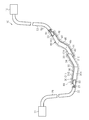
- FIG. 2 is a schematic configuration diagram illustrating a wire harness according to the first embodiment.
- (A), (b) is a schematic perspective view which shows the wire harness in 1st Embodiment.
- the wire harness 10 shown in FIG. 1 electrically connects two or three or more electrical devices (devices).
- the wire harness 10 electrically connects, for example, an inverter 11 installed at the front of a vehicle such as a hybrid vehicle or an electric vehicle, and a high-voltage battery 12 installed behind the inverter 11 to the vehicle.
- the wire harness 10 is routed under, for example, the floor of a vehicle.
- the inverter 11 is connected to a motor (not shown) for driving wheels, which is a power source for driving the vehicle.
- Inverter 11 generates AC power from DC power of high-voltage battery 12 and supplies the AC power to the motor.
- the high-voltage battery 12 is a battery that can supply a voltage of several hundred volts, for example.
- the wire harness 10 has a flexible wire 20 having one end connected to the inverter 11, a flat wire 30 having one end joined to the other end of the flexible wire 20, and a wire connected to the other end of the flat wire 30. And a flexible electric wire 50 having one end joined to the other end of the flat electric wire 40 and the other end connected to the high-voltage battery 12.
- the wire harness 10 is formed by electrically connecting different types of flexible electric wires 20, flat electric wires 30, flat electric wires 40, and flexible electric wires 50 in the length direction of the wire harness 10.
- the flexible electric wires 20 and 50 are more flexible than the flat electric wires 30 and 40.
- the flexible electric wires 20 and 50 are more flexible than the flat electric wires 30 and 40.
- These flexible electric wires 20 and 50 have higher flexibility than the flat electric wires 30 and 40.
- the flexible electric wire 20 has a core wire 21 made of a conductor and an insulating coating 22 covering the outer periphery of the core wire 21.
- the flexible electric wire 50 has a core wire 51 made of a conductor and an insulating coating 52 covering the outer periphery of the core wire 51.
- a stranded wire formed by twisting a plurality of metal wires or a braided member in which a plurality of metal wires are woven in a tubular shape can be used.
- a material of each of the core wires 21 and 51 for example, a metal material such as a copper-based or aluminum-based metal can be used. Terminals (not shown) connected to the inverter 11 and the high-voltage battery 12 are connected to the core wires 21 and 51, respectively.
- the insulating coating 22 covers, for example, the outer peripheral surface of the core wire 21 in a tightly contacting state over the entire circumference.
- the insulating coating 52 covers, for example, the outer peripheral surface of the core wire 51 in a close contact state over the entire circumference.
- the insulating coatings 22 and 52 are made of, for example, an insulating material such as a synthetic resin.
- the insulating coatings 22 and 52 can be formed by, for example, extrusion molding (extrusion coating) on the core wires 21 and 51, respectively.
- the flat electric wires 30 and 40 have rigidity capable of maintaining the shape along the wiring route of the wire harness 10.
- the flat electric wires 30 and 40 have such a rigidity that, when mounted on a vehicle, the straight or bent state is not released by vibration of the vehicle or the like.
- the flat electric wire 30 has a core wire 31 made of a conductor.
- the flat electric wire 40 has a core wire 41 made of a conductor.
- As the core wires 31 and 41 for example, a flat single core wire made of a single metal rod having a solid structure inside and having a prismatic shape (for example, a rectangular parallelepiped shape) can be used.
- the core wires 31 and 41 are formed in a long shape.
- Each of the core wires 31 and 41 is formed to extend in the length direction (axial direction) and to extend in the width direction orthogonal to the length direction, and has a predetermined thickness in the thickness direction orthogonal to the length direction and the width direction. It is a flat-plate-shaped member formed so that it may have.
- the cross-sectional shape orthogonal to the length direction of each of the core wires 31 and 41 is, for example, formed in a flat shape. I have.
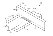
- the “flat shape” includes, for example, a rectangle and an oval.
- the “rectangle” in the present specification has a long side and a short side, and excludes a square. Further, the “rectangle” in this specification includes a shape in which a ridge is chamfered and a shape in which a ridge is rounded.
- the cross-sectional shape of the core wires 31 and 41 of the present embodiment orthogonal to the length direction (that is, the cross-sectional shape of the core wires 31 and 41 in the width direction) is rectangular.
- the cross-sectional shape orthogonal to the length direction of the core wires 31 and 41 is formed in the same rectangle over the entire length of the core wires 31 and 41 in the length direction.
- the core wire 31 has four flat portions including a pair of long side surfaces 31A and 31B including the long side of the rectangle and a pair of short side surfaces 31C and 31D including the short side of the rectangle.
- the pair of long side surfaces 31A and 31B and the pair of short side surfaces 31C and 31D are formed so as to extend over the entire length of the core wire 31 in the length direction.
- Each long side surface 31A, 31B has a larger surface area per unit length of the core wire 31 than each short side surface 31C, 31D.
- the core wire 41 has four flat portions including a pair of long side surfaces 41A and 41B including the long sides of the rectangle and a pair of short side surfaces 41C and 41D including the short sides of the rectangle. .
- the pair of long side surfaces 41A and 41B and the pair of short side surfaces 41C and 41D are formed so as to extend over the entire length of the core wire 41 in the length direction.
- Each long side surface 41A, 41B has a larger surface area per unit length of the core wire 41 than each short side surface 41C, 41D.
- a metal material such as a copper-based or aluminum-based metal can be used.
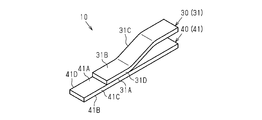
- the end portion 43 of the core wire 31 is joined to the end portion 43 of the core wire 41 in an overlapping state.
- the short side surface 31C of the end portion 33 is joined to the long side surface 41A of the end portion 43 in a superimposed state.
- the end 33 is joined to the long side 41A of the end 43 in a state where the end 33 is overlapped such that the short side 31C of the end 33 contacts the long side 41A. .
- the long side surface 41A of the core wire 41 and the short side surface 31C of the core wire 31 are joined, and the core wire 31 and the core wire 41 are electrically connected.
- the joint area between the long side surface 41A of the core wire 41 and the short side surface 31C of the core wire 31 is, for example, a cross section orthogonal to the length direction of the core wire 31 (that is, a cross section in the width direction).
- a joining method of the core wire 31 and the core wire 41 for example, ultrasonic welding can be used.
- a resonator called a horn is brought into contact with a part of the object to be joined (here, the core wires 31 and 41) to apply ultrasonic vibration to the object to be joined, and the vibration energy is applied to the object to be joined.
- the resonator contacts the long side surface 41B opposite to the long side surface 41A to which the short side surface 31C of the core wire 31 is joined, and ultrasonic vibration is applied to the long side surface 41B.
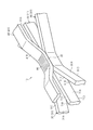
- the flat electric wires 30 and 40 are arranged so as to be bent, for example, three-dimensionally.
- the flat electric wires 30 and 40 are, for example, routed under the floor of a vehicle, and are bent in a predetermined shape according to the configuration under the floor and are routed.
- the flat electric wire 40 according to the present embodiment includes a straight portion 44 extending along the vehicle front-rear direction, a bent portion 45 provided at an end of the straight portion 44, and an extension extending upward from the bent portion 45 toward the vehicle. It has a portion 46, a bent portion 47 provided at an end of the extension portion 46, and a straight portion 48 extending from the bent portion 47 along the vehicle front-rear direction.
- the straight portion 44 has an end 43 to which the short side surface 31C of the core wire 31 is joined.
- the flat electric wire 30 of the present embodiment includes a straight portion 34 extending along the vehicle front-rear direction, a bent portion 35 provided at an end of the straight portion 34, and (Extending toward the side).
- the straight portion 34 has an end 33 to which the long side surface 41A of the core wire 41 is joined.
- the extending portion 36 is formed so as to extend in a direction (vehicle width direction) orthogonal to a direction in which the linear portions 34, 44, 48 extend (vehicle longitudinal direction) and a direction in which the extending portion 46 extends (vehicle vertical direction). Have been.
- the flat wire 30 and the flat wire 40 are formed so as to bend in different directions from each other.
- the flat electric wire 40 is bent so as to extend in a vehicle vertical direction from a straight line portion 44 extending in the vehicle longitudinal direction.
- the flat electric wire 30 is bent so as to extend in the vehicle width direction from the straight portion 34 extending in the vehicle front-rear direction.
- the flat electric wires 30 and 40 are three-dimensionally bent so as to extend in three directions of the vehicle front-rear direction, the vehicle vertical direction, and the vehicle width direction.
- the bent portions 45 and 47 are formed so as to bend the core wire 41 in the thickness direction (short side direction).
- the bent portions 45 and 47 are formed such that the long side surface 41A is bent in the middle of the length direction so that the cross section in the thickness direction of the core wire 41 is curved.
- the bent portions 45 and 47 are bent at substantially the same curvature over the entire length of the long side surface 41A in the width direction (long side direction). In other words, the bent portions 45 and 47 are not portions formed by twisting the long side surface 41A.
- the cross section in the thickness direction of the core wires 31 and 41 is a cross section obtained by cutting the core wires 31 and 41 by a plane extending in parallel with the length direction of the core wires 31 and 41 and extending in the thickness direction of the core wires 31 and 41 (that is, (A cross section parallel to the long side surfaces 31A, 31B, 41A, 41B).
- the bent portion 35 is formed so that the core wire 31 is bent in the thickness direction (short side direction).
- the bent portion 35 is formed such that the long side surface 31A is bent in the middle of the length direction so that the cross section in the thickness direction of the core wire 31 is curved.
- the bent portion 35 is bent at substantially the same curvature over the entire length of the long side surface 31A in the width direction (long side direction). In other words, the bent portion 35 is not a portion formed by twisting the long side surface 31A.
- the manner of joining the core wire 21 of the flexible electric wire 20 and the core wire 31 of the flat electric wire 30 and the manner of joining the core wire 51 of the flexible electric wire 50 and the core wire 41 of the flat electric wire 40 will be described.
- the end 23 of the core wire 21 is exposed from the insulating coating 22.
- the end 23 of the core wire 21 is joined, for example, in a state of being superimposed on the end of the long side surface 31A of the core wire 31.
- the end portion 23 of the core wire 21 of the present embodiment is joined in a state of being superimposed on the long side surface 31A of the extension 36 of the core wire 31. Thereby, the core wire 21 and the core wire 31 are electrically connected.
- ultrasonic welding can be used as a joining method of the core wire 21 and the core wire 31.
- the end 23 of the core wire 21 is crushed by being clamped together with the core wire 31 by a well-known ultrasonic welding jig (not shown).
- the strands of the core wire 21 are welded.
- the end 53 of the core wire 51 is exposed from the insulating coating 52.
- the end portion 53 of the core wire 51 is joined, for example, in a state of being superimposed on the end portion of the long side surface 41A of the core wire 41.
- the end portion 53 of the core wire 51 of the present embodiment is joined in a state of being superimposed on the long side surface 41A of the linear portion 48 of the core wire 41.
- the core wire 41 and the core wire 51 are electrically connected.
- a joining method of the core wire 41 and the core wire 51 for example, ultrasonic welding can be used in the same manner as the joining method of the core wire 21 and the core wire 31.
- the order of the joining process of the core wires 21, 31, 41, 51 and the bending process of the core wires 31, 41 are not particularly limited.
- the short side surface 31C of the core wire 31 to which the core wire 21 is joined is changed to the long side of the core wire 41 to which the core wire 51 is joined.
- the core wires 31 and 41 may be bent to form the bent portions 35, 45 and 47 on the core wires 31 and 41.
- the joining process of the core wires 21, 31, 41 and 51 may be performed.
- the flat electric wires 30 and 40 are covered with, for example, an insulating member 60.
- the insulating member 60 is formed so as to cover, for example, a connection portion between the flat wire 30 and the flexible wire 20 and a connection portion between the flat wire 40 and the flexible wire 50.
- the insulating member 60 is formed, for example, so as to be bridged between the insulating coating 22 of the flexible electric wire 20 and the insulating coating 52 of the flexible electric wire 50.
- One end of the insulating member 60 covers the outer peripheral surface of the terminal portion of the insulating coating 22, and the other end of the insulating member 60 covers the outer peripheral surface of the terminal portion of the insulating coating 52.
- the insulating members 60 ensure electrical insulation of the core wires 31 and 41 and the core wires 21 and 51 exposed from the insulating coatings 22 and 52, respectively.
- a shrink tube for example, a rubber tube, an insulating tape, a hard protector made of synthetic resin, or a combination thereof can be used.
- a shrink tube for example, a heat shrink tube can be used.
- the flat wire 40 corresponds to the first wire
- the core wire 41 corresponds to the first wire
- the long side surface 41A corresponds to the first flat portion
- the flat wire 30 corresponds to the second wire
- the core wire 31 corresponds to the second core wire
- the short side surface 41C corresponds to the second plane portion.
- the core wire 41 of the flat electric wire 40 has a long side surface 41A (flat portion) extending over the entire length in the length direction, and the core wire 31 of the flat electric wire 30 is in the length direction. It has a short side surface 31C (flat portion) extending over the entire length. Then, the bonding was performed in a state where the short side surface 31C of the core wire 31 was superimposed on the long side surface 41A of the core wire 41.
- the wire harness 10 can be manufactured by easily joining the core wires 31 and 41 of the flat electric wires 30 and 40 to each other.
- the core wire 41 Since the core wire 41 has the long side surface 41A (flat portion) extending over the entire length in the length direction, the core wire 31 can be joined to an arbitrary position on the long side surface 41A. . Further, since the core wire 31 has the short side surface 31C (flat portion) extending over the entire length in the length direction, the core wire 41 can be joined to an arbitrary position on the short side surface 31C. Thereby, the joining position between the core wire 31 and the core wire 41 can be easily changed, so that the tolerance absorption allowance can be easily secured.
- the cross-sectional shape orthogonal to the length direction of the core wires 31 and 41 was formed in a rectangular shape. According to this configuration, the rigidity of the core wires 31 and 41 is relatively high in the cross-sectional shape orthogonal to the length direction, that is, in the long side direction (width direction) of the rectangle, and compared in the short side direction (thickness direction). Target. Therefore, bending of the core wires 31 and 41 in the short side direction becomes easy.
- the core wire 31 is joined in a state where the core wire 31 is overlapped so that the short side surface 31C of the core wire 31 contacts the long side surface 41A of the core wire 41.
- the core wire 31 not only the long side surfaces 31A and 31B of the core wire 31 but also the short side surfaces 31C and 31D of the core wire 31 can be used as joint surfaces of the core wires 31 and 41.
- the short side surfaces 41C and 41D of the core wire 41 can also be used as joining surfaces of the core wires 31 and 41. This increases the number of planes that can be used as joint surfaces among the core wires 31 and 41, so that the degree of freedom of the wiring route (layout) of the wire harness 10 can be increased.
- the short side direction of the core wire 31 and the short side direction of the core wire 41 can be shifted by 90 degrees at the joint. . Therefore, the direction in which the core wire 31 is easily bent can be shifted by about 90 degrees from the direction in which the core wire 41 is easily bent. As a result, the degree of freedom of the wiring route (layout) of the wire harness 10 can be increased while using the flat flat electric wires 30 and 40 in which the direction in which bending is easy is restricted.
- the long side surface 41A and the short side surface 31C are joined so that the joint area between the long side surface 41A of the core wire 41 and the short side surface 31C of the core wire 31 is equal to or greater than the area of the width direction cross section of the core wires 31 and 41. It was made to join. Thereby, the connection reliability between the core wire 31 and the core wire 41 can be improved. At this time, the size of the joint area between the long side surface 41A and the short side surface 31C can be easily adjusted by adjusting the distance in the length direction of the core wire 31 joined to the long side surface 41A of the core wire 41, for example. be able to.
- both ends of the wire harness 10 have excellent flexibility in order to easily perform a connection operation with an electric device such as the inverter 11 or the high-voltage battery 12.
- the flexible wire 20 is joined to the end of the flat wire 30, and the flexible wire 50 is joined to the end of the flat wire 40.
- both ends of the wire harness 10 can be easily bent. For this reason, connection work with electric equipment such as the inverter 11 and the high-voltage battery 12 can be easily performed.
- the wire harness 10 has flat electric wires 70 and 80 connected to electric equipment (not shown) different from the inverter 11 and the high-voltage battery 12 shown in FIG.
- the flat electric wires 70 and 80 are electrically connected to the flat electric wires 30 and 40.
- the flat electric wires 30, 70, and 80 supply the electric power supplied to the flat electric wire 40 to various electric devices.
- the flat wire 40 functions as a trunk wire
- the flat wires 30, 70, and 80 function as branch wires.
- the flat electric wires 70 and 80 have the same configuration as the flat electric wires 30 and 40, and have core wires 71 and 81, respectively.
- the cross-sectional shape orthogonal to the length direction of the core wires 71 and 81 is formed in the same rectangle over the entire length of the core wires 71 and 81 in the length direction.
- the core wire 71 has four flat portions including a pair of long side surfaces 71A and 71B including the long side of the rectangle and a pair of short side surfaces 71C and 71D including the short side of the rectangle.
- the core wire 81 has four flat portions including a pair of long side surfaces 81A and 81B including the long side of the rectangle and a pair of short side surfaces 81C and 81D including the short side of the rectangle.
- a metal material such as a copper-based or aluminum-based material can be used.
- a plurality of (here, three) core wires 31, 71, 81 are individually overlapped and joined to the long side surface 41A of the intermediate portion 49 in the length direction of the core wire 41.
- the core wires 31, 71, and 81 are joined in a state where the short sides 31 C, 71 C, and 81 C are in contact with the long side 41 A of the intermediate portion 49. Thereby, the core wire 41 and the core wires 31, 71, 81 are electrically connected.
- the short sides 31C, 71C, and 81C at the intermediate portions in the length direction of the core wires 31, 71, and 81 are joined in a state where the short sides 31C, 71C, and 81C are overlapped with the long side surface 41A at the intermediate portion 49.
- the core wires 31, 71, 81 may or may not be in contact with each other in the intermediate portion 49.
- the plurality of core wires 31, 71, 81 are arranged on the long side surface 41A of the intermediate portion 49 along the width direction of the long side surface 41A.
- the short side surfaces 31C, 71C, 81C of the plurality of core wires 31, 71, 81 are joined to one long side surface 41A at the same position in the length direction of the core wire 41 (here, the intermediate portion 49). Thereby, the joints between the core wire 41 and the core wires 31, 71, 81 can be combined into one. Therefore, the core wire 41 and the core wires 31, 71, 81 can be joined together (that is, in one joining step).
- the resonator contacts the long side surface 41B opposite to the long side surface 41A to which the short side surfaces 31C, 71C, 81C of the core wires 31, 71, 81 are joined, and the long side surface 41B is brought into contact with the resonator. Ultrasonic vibration is applied. For this reason, a trace M1 (see the hatched area in the figure) is formed on the long side surface 41B in the intermediate portion 49 of the core wire 41, where the resonator is in contact with and the ultrasonic vibration is applied.
- the plurality of core wires 31, 71, 81 are, for example, bent so as to extend in mutually different directions.
- the flexible wires similar to the flexible wires 20 and 50 may be connected to the ends of the core wires 31, 41, 71 and 81.
- the flat electric wires 70 and 80 correspond to the third electric wire
- the core wires 71 and 81 correspond to the third core wire
- the short side surfaces 71C and 81C correspond to the third flat portion. According to the present embodiment described above, the following functions and effects can be obtained in addition to the functions and effects (1) to (9) of the first embodiment.
- a plurality of short side surfaces 31C, 71C, 81C are individually overlapped and joined to one long side surface 41A (flat portion). Thereby, the degree of freedom of the wiring route of the wire harness 10 can be increased as compared with the case where only one core wire can be joined to one long side surface 41A.
- the plurality of flat electric wires 30, 70, 80 are provided on the long side surface 41A of the core wire 41 so as to be arranged along the width direction of the long side surface 41A. Further, the short side surfaces 31C, 71C, 81C of the core wires 31, 71, 81 were joined to the long side surface 41A at the same position in the length direction of the core wire 41. Thus, the joint between the core wire 41 and the core 31, the joint between the core 41 and the core 71, and the joint between the core 41 and the core 81 can be combined into one. Therefore, the core wire 41 and the plurality of core wires 31, 71, 81 can be joined together (that is, in one joining step). As a result, the number of manufacturing steps for manufacturing the wire harness 10 can be reduced.
- the short side surfaces 31C, 71C, 81C of the core wires 31, 71, 81 are joined to the long side surface 41A of the intermediate portion 49 in the length direction of the core wire 41.
- the joining of the core wires 31, 41, 71, 81 at the branch portion of the wire harness 10 can be easily performed. Therefore, the degree of freedom of wiring of the wire harness 10 can be increased.
- the resonator is brought into contact with the long side surface 41B opposite to the long side surface 41A to which the short side surfaces 31C, 71C and 81C are joined, and ultrasonic vibration is applied to the long side surface 41B.
- the long side surface 41B and the long side surface 41A on the opposite side to the long side surface 41B are formed in a plane, and from the long side surface 41B to the bonding interface with the short side surfaces 31C, 71C, 81C. are approximately equal.
- each of the long sides 41A and the short sides 31C, 71C, 81C is different. Vibration energy can be evenly applied to the bonding interface. Therefore, the long side surface 41A and the short side surfaces 31C, 71C, 81C can be stably bonded.
- the joints between the core wire 41 and the plurality of core wires 31, 71, 81 are combined at one place, but the present invention is not limited to this.
- the joint between the core 41 and the core 31, the joint between the core 41 and the core 71, and the joint between the core 41 and the core 81 may be provided at positions separated from each other in the length direction of the core 41. Good.
- the joint surface between the short side surfaces 31C, 71C, 81C of the core wires 31, 71, 81 and the long side surface 41A of the core wire 41 is extended along the length direction of the long side surface 41A.
- the joint surface between the short side surfaces 31C, 71C, 81C of the core wires 31, 71, 81 and the long side surface 41A of the core wire 41 may be formed so as to extend along the width direction of the long side surface 41A.
- the core wire 71 may be joined to the long side surface 41A of the core wire 41 so as to cross the long side surface 41A.
- the short side surface 71C is overlapped with the long side surface 41A of the core wire 41 such that the length direction of the short side surface 71C of the core wire 71 intersects the length direction of the long side surface 41A.
- the joint surface (see the hatched area in the figure) between the short side surface 71C of the core wire 71 and the long side surface 41A of the core wire 41 is formed so as to extend along the width direction of the long side surface 41A. Since such a joining form can be adopted, the degree of freedom of wiring of the wire harness 10 can be improved.
- the flat wire 30 may be omitted from the wire harness 10 shown in FIG. As shown in FIG. 5, the flat wires 30 and 90 may be joined to both the pair of long side surfaces 41A and 41B (flat portions) of the core wire 41.
- the flat electric wire 90 is connected to, for example, an electric device (not shown) different from the inverter 11 and the high-voltage battery 12 shown in FIG.
- the flat electric wire 90 has the same configuration as the flat electric wires 30 and 40, and has a core wire 91.
- the cross-sectional shape orthogonal to the length direction of the core wire 91 is formed in the same rectangle over the entire length of the core wire 91 in the length direction.
- the core wire 91 has four flat portions including a pair of long side surfaces 91A and 91B including the long sides of the rectangle and a pair of short side surfaces 91C and 91D including the short sides of the rectangle.
- the short side surface 31C of the core wire 41 is joined to the long side surface 41A of the core wire 41 in a state of being superimposed on the long side surface 41A of the core wire 41, and the short side surface 91C of the core wire 91 is superimposed on the long side surface 41B of the core wire 41. It is joined in the state where it was done. Thereby, since both the long side surfaces 41A and 41B of the core wire 41 can be used as the joint surface, the degree of freedom of the wiring route of the wire harness 10 can be increased.
- the short side surface 31C of the core wire 31 and the short side surface 91C of the core wire 91 are provided so as to oppose each other with the core wire 41 interposed therebetween at the joint of the core wires 31, 41, 91. Thereby, the joining process of the core wires 31 and 41 and the joining process of the core wires 41 and 91 can be collectively performed.
- the flat wire 90 corresponds to the fourth wire
- the core wire 91 corresponds to the fourth core wire
- the short side surface 91C corresponds to the fourth flat portion
- the long side surface 41B of the core wire 41 corresponds to the fourth wire portion. This corresponds to the fifth plane portion.
- the joint between the core wires 41 and 91 and the joint between the core wires 31 and 41 may be provided at positions separated from each other in the longitudinal direction of the long side surface 41A. Further, the joint between the core wires 41 and 91 and the joint between the core wires 31 and 41 may be provided at positions separated from each other in the width direction of the long side surface 41A.
- the short side surfaces 31C, 71C, 81C, 91C of the core wires 31, 41, 71, 81, 91 are joined to the long side surface 41A of the core wire 41.
- the present invention is not limited to this.
- all the flat portions of the core wires 31, 41, 71, 81, 91 can be used as joining surfaces.
- the long side surface 31A of the core wire 31 may be joined to the long side surface 41A of the core wire 41 in an overlapping state.
- the long side surface 91A of the core wire 91 may be joined to the long side surface 41B of the core wire 41 in a state of being overlapped.
- the joint positions of the core wires 31, 41, 71, 81, 91 in each of the above-described embodiments and the above-described modified examples may be set at arbitrary positions in the length direction of the core wires 31, 41, 71, 81, 91. it can.
- the flexible wires similar to the flexible wires 20 and 50 may be connected to the ends of the core wires 31, 41, 71, 81 and 91 in each of the above modifications.
- -A flexible electric wire may be joined to the short side surfaces 31C, 41C, 71C, 81C, and 91C of the core wires 31, 41, 71, 81, and 91 in each of the embodiments and the modifications.
- a through-hole 41X penetrating the core wire 41 of the flat wire 40 in the thickness direction may be provided. That is, the core wire 41 may be provided with a through hole 41X penetrating from the long side surface 41A to the long side surface 41B of the core wire 41.
- the flat electric wire 40 can be attached to a mounting target of the vehicle by the screw 100 inserted into the through hole 41X.
- the flexible electric wire 50 may be omitted.
- the through hole 41X may be provided at an intermediate portion in the length direction of the core wire 41.
- the flat electric wire 30 in each of the above-described embodiments and the above-described modified examples may have an insulating coating that covers the outer periphery of the core wire 31 like the flexible electric wires 20 and 50.
- the insulating coating of the portion of the core wire 31 to be joined to the core wire 41 and the portion to be joined to the core wire 21 may be partially removed.
- the flat electric wires 40, 70, 80, 90 can be similarly changed.
- the cross-sectional shape orthogonal to the length direction of the core wires 31, 41, 71, 81, 91 in each of the above embodiments and the above modifications is not limited to a rectangle.
- the core wires 31, 41, 71, 81, 91 may have a flat portion extending over the entire length in the length direction, and the cross-sectional shape orthogonal to the length direction may be a square or a pentagon. Or an oval shape.
- the method of joining the core wires is not limited to ultrasonic welding, and other joining methods such as solder joining, resistance welding, and laser welding can also be used.
- a configuration in which an exterior member that protects the flexible electric wires 20, 50, the flat electric wires 30, 40, and the like may be provided.
- a configuration in which an electromagnetic shield member is provided inside the exterior member may be adopted.
- the exterior member for example, a corrugated tube, a twist tube, a hard resin pipe, or a metal pipe can be used.
- a composite pipe or the like in which a conductive shield layer is laminated or embedded in a nonmetallic pipe main body can be used.
- the electromagnetic shield member for example, a braided wire or a metal foil having flexibility can be used.
- the wire harness 10 of each of the above embodiments is not limited to a high-voltage battery such as a high-voltage battery, and can be widely applied to a wire harness that connects at least two electrical devices that are electrically connected.
- the core wires 31 and 41 in the illustrated embodiment are representative examples of the first and second conductive metal flat plates.
- Each core 31, 41 of the illustrated embodiment can have first and second major surfaces, first and second elongated sides, and first and second end surfaces.
- the long side surfaces 31A and 31B of the illustrated embodiment are representative examples of the main surface of the first conductive metal flat plate.
- the long side surfaces 41A and 41B of the illustrated embodiment are representative examples of the main surface of the second conductive metal flat plate.
- the short side surfaces 31C, 31D, 71C, 81C, and 91c of the illustrated embodiment are representative examples of the first and second long side surfaces of the first conductive metal flat plate.
- both end faces in the longitudinal direction are representative examples of the first and second end faces of the conductive metal flat plate.
- the distance range selected from the first end face (for example, the length range corresponding to the length of the flat joint surface of the end portion 23 of the core wire 21) is set to the first conductive metal flat plate. It may be called the first end.
- the distance range selected from the second end face (for example, the length range corresponding to the length of the joint surface between the first conductive metal flat plate and the second conductive metal flat plate) is set to the second range. It may be referred to as the second end of one conductive metal flat plate.
- a distance range selected from the first end face (for example, a length range corresponding to a length of a joining surface between the first conductive metal flat plate and the second conductive metal flat plate) is set to a second range. It may be referred to as the first end of a two-conductive metal plate.
- a selected distance range (for example, a length range corresponding to the length of the flat joint surface of the end portion 53 of the core wire 51) from the second end face is set to the second conductive metal flat plate. May be referred to as a second end.
- a wire harness (10) includes: A first stranded metal wire (21) having an end (23); A second stranded metal wire (51) having an end (53); A first end surface, a second end surface opposite to the first end surface in the longitudinal direction, a length defined by the first end surface and the second end surface, a first main surface, and the second end surface in a thickness direction. A second main surface opposite to the first main surface, a constant thickness defined by the first main surface and the second main surface, a first long side surface, and the first long side in a width direction.
- a first conductive metal flat plate (31) defined by a second elongated side surface opposite to the side surface, and defined by the first elongated side surface and the second elongated side surface and having a constant width over the length; )When, A first end surface, a second end surface opposite to the first end surface in the longitudinal direction, a length defined by the first end surface and the second end surface, a first main surface, and the second end surface in a thickness direction. A second main surface opposite to the first main surface, a constant thickness defined by the first main surface and the second main surface, a first long side surface, and the first long side in a width direction.
- a second conductive metal flat plate (41) defined by a second elongated side surface opposite to the side surface, and defined by the first elongated side surface and the second elongated side surface and having a constant width over the length.
- the end (23) of the first metal stranded wire (21) is located near the first end face of the first conductive metal flat plate (31).
- the end portion (53) of the second metal stranded wire (51) is connected to the first main portion of the second metal stranded wire (51) near the second end surface of the second conductive metal flat plate (41).
- the first conductive metal flat plate (31), the first main surface, and the first main surface of the second conductive metal flat plate (41) have a T-shaped connection profile or an L-shaped connection profile.
- a part of the first long side surface of one conductive metal flat plate (31) and a part of the first main surface of the second conductive metal flat plate (41) are electrically and mechanically connected. I have.
- One or both of the first metal stranded wire (21) and the second conductive metal flat plate (41) may be a bent flat plate having at least one bent portion (35, 45, 47).
- the first joining surface of the first metal stranded wire (21) and the second joining surface of the second conductive metal flat plate (41) can be directly connected by welding.
- the first joining surface of the first metal stranded wire (21) and the second joining surface of the second conductive metal flat plate (41) may be directly connected by ultrasonic welding. it can.
- the end portion (23) of the first metal stranded wire (21) may have a maximum width smaller than the width of the first conductive metal flat plate (31).
- the end portion (53) of the second metal stranded wire (51) may have a maximum width smaller than the width of the second conductive metal flat plate (41).
- Each metal stranded wire (21, 51) has a non-end except for the end (23, 51), and the end (23, 53) of each metal stranded wire (21, 51) is The crushed end of each of the metal stranded wires (21, 51) may be thinner than the non-end.
- the wire harness is configured to be routed along a predetermined route including under the floor of the vehicle, and the first and second conductive metal flat plates (31, 41) are arranged in the predetermined manner. May be configured so as to maintain a shape suitable for the entire underfloor or predetermined portion of the route.
Landscapes
- Engineering & Computer Science (AREA)
- Mechanical Engineering (AREA)
- Insulated Conductors (AREA)
- Processing Of Terminals (AREA)
Abstract
ワイヤハーネス10は、芯線31を有する平型電線30と、芯線41を有する平型電線40とを有している。芯線31は、その芯線31の長さ方向の全長に亘って延在する平面部である短辺面31Cを有している。芯線41は、その芯線41の長さ方向の全長に亘って延在する平面部である長辺面41Aを有している。そして、長辺面41Aに短辺面31Cが重ね合わされた状態で芯線31,41が接合されている。
Description
本発明は、ワイヤハーネスに関する。
従来、車両に配索されるワイヤハーネスとしては、複数の電線を有し、それら電線の芯線同士が互いに接合されたものが知られている(例えば、特許文献1参照)。この種のワイヤハーネスは、芯線として複数の素線が撚り合わされた撚線を有する撚線電線と、芯線として断面円形状の単芯線を有する単芯線電線とを有している。撚線電線の端部には、素線が露出する素線露出部が設けられている。単芯線電線の端部には、単芯線が露出する導体露出部が設けられている。導体露出部には、圧潰部が設けられており、この圧潰部の平面部分に対して、素線露出部が超音波溶接によって接合されている。
ところで、上記ワイヤハーネスにおいては、複数の電線の芯線同士を接合する上で、単芯線電線の導体露出部を圧潰する工程が必要となる。こうした工程においては、芯線同士の接合部分に歪みが生じないように、導体露出部を所定の形状に高い精度にて成形することが求められる。このため、成形工程が煩雑になりやすく、ワイヤハーネスの製造を容易に行う上で、改善の余地を残すものとなっている。
本発明の目的は、芯線同士を容易に接合することができるワイヤハーネスを提供することにある。
上記課題を解決するワイヤハーネスは、第1芯線を有する第1電線と第2芯線を有する第2電線とを有し、前記第1芯線と前記第2芯線とが互いに接合されているワイヤハーネスであって、前記第1芯線は、前記第1芯線の長さ方向の全長に亘って延在する第1平面部を有しており、前記第2芯線は、前記第2芯線の長さ方向の全長に亘って延在する第2平面部を有しており、前記第1平面部に前記第2平面部が重ね合わされた状態で接合されている。
本発明によれば、芯線同士を容易に接合することができる。
以下、添付図面を参照して各実施形態を説明する。なお、添付図面は、説明の便宜上、構成の一部を誇張又は簡略化して示す場合がある。また、各部分の寸法比率についても、実際とは異なる場合がある。
(第1実施形態)
以下、図1及び図2に従って、ワイヤハーネスの第1実施形態について説明する。
図1に示すワイヤハーネス10は、2個又は3個以上の電気機器(機器)を電気的に接続する。ワイヤハーネス10は、例えば、ハイブリッド車や電気自動車等の車両の前部に設置されたインバータ11と、そのインバータ11よりも車両の後方に設置された高圧バッテリ12とを電気的に接続する。ワイヤハーネス10は、例えば、車両の床下等を通るように配索される。インバータ11は、車両走行の動力源となる車輪駆動用のモータ(図示略)と接続される。インバータ11は、高圧バッテリ12の直流電力から交流電力を生成し、その交流電力をモータに供給する。高圧バッテリ12は、例えば、数百ボルトの電圧を供給可能なバッテリである。
ワイヤハーネス10は、インバータ11に接続される一端を有する可撓電線20と、可撓電線20の他端に接合された一端を有する平型電線30と、平型電線30の他端に接合された一端を有する平型電線40と、平型電線40の他端に接合された一端及び高圧バッテリ12に接続される他端を有する可撓電線50とを有している。ワイヤハーネス10は、種類の異なる可撓電線20と平型電線30と平型電線40と可撓電線50とをワイヤハーネス10の長さ方向に電気的に接続してなるものである。
可撓電線20,50は、平型電線30,40よりも可撓性に優れている。可撓電線20,50は、平型電線30,40よりも柔軟性に優れている。これら可撓電線20,50は、平型電線30,40よりも高い屈曲性を有している。
可撓電線20は、導体よりなる芯線21と、芯線21の外周を被覆する絶縁被覆22とを有している。可撓電線50は、導体よりなる芯線51と、芯線51の外周を被覆する絶縁被覆52とを有している。各芯線21,51としては、例えば、複数の金属素線を撚り合わせてなる撚り線や、複数の金属素線が筒状に編み込まれた編組部材を用いることができる。各芯線21,51の材料としては、例えば、銅系やアルミニウム系などの金属材料を用いることができる。各芯線21,51には、インバータ11及び高圧バッテリ12にそれぞれ接続される端子(図示略)が接続されている。
絶縁被覆22は、例えば、芯線21の外周面を全周に亘って密着状態で被覆している。絶縁被覆52は、例えば、芯線51の外周面を全周に亘って密着状態で被覆している。絶縁被覆22,52は、例えば、合成樹脂などの絶縁材料によって構成されている。絶縁被覆22,52は、例えば、芯線21,51に対する押出成形(押出被覆)によってそれぞれ形成することができる。
平型電線30,40は、ワイヤハーネス10の配索経路に沿う形状を維持可能な剛性を有している。例えば、平型電線30,40は、車両に搭載された状態において、車両の振動等によって直線状又は曲げられた状態が解除されない程度の剛性を有している。平型電線30は、導体よりなる芯線31を有している。平型電線40は、導体よりなる芯線41を有している。芯線31,41としては、例えば、内部が中実構造をなす角柱状(例えば、直方体状)の1本の金属棒からなる平型の単芯線を用いることができる。芯線31,41は、長尺状に形成されている。
各芯線31,41は、長さ方向(軸線方向)に延び、且つ長さ方向と直交する幅方向に延びるように形成されるとともに、長さ方向及び幅方向と直交する厚み方向に所定の厚みを有するように形成された平板状部材である。各芯線31,41の長さ方向に直交する断面形状(つまり、芯線31,41の長さ方向と直交する平面によって芯線31,41を切断した断面形状)は、例えば、扁平形状に形成されている。本明細書において、「扁平形状」には、例えば、長方形や長円形などが含まれる。また、本明細書における「長方形」は、長辺と短辺を有するものであり、正方形を除いたものである。また、本明細書における「長方形」には、稜部を面取りした形状や、稜部を丸めた形状も含まれる。
図2(a)に示すように、本実施形態の芯線31,41の長さ方向に直交する断面形状(つまり、芯線31,41の幅方向断面の形状)は、長方形に形成されている。芯線31,41の長さ方向に直交する断面形状は、芯線31,41の長さ方向の全長に亘って同一の長方形に形成されている。芯線31は、上記長方形の長辺を含む一対の長辺面31A,31Bと、上記長方形の短辺を含む一対の短辺面31C,31Dとの4つの平面部を有している。これら一対の長辺面31A,31B及び一対の短辺面31C,31Dは、芯線31の長さ方向の全長に亘って延在するように形成されている。各長辺面31A,31Bは、各短辺面31C,31Dよりも芯線31の単位長さ当たりの表面積が大きい。同様に、芯線41は、上記長方形の長辺を含む一対の長辺面41A,41Bと、上記長方形の短辺を含む一対の短辺面41C,41Dとの4つの平面部を有している。これら一対の長辺面41A,41B及び一対の短辺面41C,41Dは、芯線41の長さ方向の全長に亘って延在するように形成されている。各長辺面41A,41Bは、各短辺面41C,41Dよりも芯線41の単位長さ当たりの表面積が大きい。芯線31,41の材料としては、例えば、銅系やアルミニウム系などの金属材料を用いることができる。
次に、平型電線30と平型電線40との接合態様について説明する。
図2(b)に示すように、芯線41の端部43には、芯線31の端部33が重ね合わされた状態で接合されている。端部43における長辺面41Aには、端部33における短辺面31Cが重ね合わされた状態で接合されている。具体的には、端部43における長辺面41A上に、その長辺面41Aに対して端部33における短辺面31Cが接触するように端部33が重ね合わされた状態で接合されている。これにより、芯線41の長辺面41Aと芯線31の短辺面31Cとが接合されており、芯線31と芯線41とが電気的に接続されている。このとき、芯線41の長辺面41Aと芯線31の短辺面31Cとの接合面積(図中のハッチング領域参照)は、例えば、芯線31の長さ方向に直交する断面(つまり、幅方向断面)の面積以上になるように形成されている。芯線31と芯線41との接合方法としては、例えば、超音波溶接を用いることができる。ここで、超音波溶接は、ホーンと呼ばれる共振体を接合対象物(ここでは、芯線31,41)の一部に接触させて接合対象物に超音波振動を加え、その振動エネルギーが接合対象物同士の接合界面に付与されることによって該接合界面に発生する摩擦熱を利用して溶着する方法である。例えば、芯線31の短辺面31Cが接合される長辺面41Aとは反対側の長辺面41Bに共振体が接触され、その長辺面41Bに超音波振動が加えられる。
図2(b)に示すように、芯線41の端部43には、芯線31の端部33が重ね合わされた状態で接合されている。端部43における長辺面41Aには、端部33における短辺面31Cが重ね合わされた状態で接合されている。具体的には、端部43における長辺面41A上に、その長辺面41Aに対して端部33における短辺面31Cが接触するように端部33が重ね合わされた状態で接合されている。これにより、芯線41の長辺面41Aと芯線31の短辺面31Cとが接合されており、芯線31と芯線41とが電気的に接続されている。このとき、芯線41の長辺面41Aと芯線31の短辺面31Cとの接合面積(図中のハッチング領域参照)は、例えば、芯線31の長さ方向に直交する断面(つまり、幅方向断面)の面積以上になるように形成されている。芯線31と芯線41との接合方法としては、例えば、超音波溶接を用いることができる。ここで、超音波溶接は、ホーンと呼ばれる共振体を接合対象物(ここでは、芯線31,41)の一部に接触させて接合対象物に超音波振動を加え、その振動エネルギーが接合対象物同士の接合界面に付与されることによって該接合界面に発生する摩擦熱を利用して溶着する方法である。例えば、芯線31の短辺面31Cが接合される長辺面41Aとは反対側の長辺面41Bに共振体が接触され、その長辺面41Bに超音波振動が加えられる。
図1に示すように、平型電線30,40は、例えば、3次元状に曲げられるように配索されている。平型電線30,40は、例えば、車両の床下を通って配索されるものであり、その床下の構成に応じた所定形状に曲げて配索される。本実施形態の平型電線40は、車両前後方向に沿って延びる直線部44と、直線部44の端部に設けられた屈曲部45と、屈曲部45から車両上方側に延出する延出部46と、延出部46の端部に設けられた屈曲部47と、屈曲部47から車両前後方向に沿って延びる直線部48とを有している。直線部44は、芯線31の短辺面31Cが接合される端部43を有している。本実施形態の平型電線30は、車両前後方向に沿って延びる直線部34と、直線部34の端部に設けられた屈曲部35と、屈曲部35から車両幅方向(ここでは、紙面奥側)に向かって延出する延出部36とを有している。直線部34は、芯線41の長辺面41Aが接合される端部33を有している。延出部36は、直線部34,44,48が延びる方向(車両前後方向)及び延出部46が延びる方向(車両上下方向)と直交する方向(車両幅方向)に向かって延びるように形成されている。すなわち、平型電線30と平型電線40とは互いに異なる方向に曲がるように形成されている。具体的には、平型電線40は、車両前後方向に延びる直線部44から車両上下方向に延びるように屈曲されている。また、平型電線30は、車両前後方向に延びる直線部34から車両幅方向に延びるように屈曲されている。このように、平型電線30,40は、車両前後方向と車両上下方向と車両幅方向との3方向それぞれに延びるように3次元状に屈曲されている。
ここで、屈曲部45,47は、芯線41を厚み方向(短辺方向)に曲げるようにして形成されている。屈曲部45,47は、長辺面41Aを長さ方向の途中で折れ曲げて、芯線41の厚み方向断面が湾曲するように形成されている。屈曲部45,47では、長辺面41Aの幅方向(長辺方向)の全長に亘って略同一の曲率で曲げられている。換言すると、屈曲部45,47は、長辺面41Aを捻って形成した部分ではない。ここで、芯線31,41の厚み方向断面は、芯線31,41の長さ方向に平行して延び、且つ芯線31,41の厚み方向に延びる平面によって芯線31,41を切断した断面(つまり、長辺面31A,31B,41A,41Bに平行な断面)である。
屈曲部35は、芯線31を厚み方向(短辺方向)に曲げるようにして形成されている。屈曲部35は、長辺面31Aを長さ方向の途中で折れ曲げて、芯線31の厚み方向断面が湾曲するように形成されている。屈曲部35では、長辺面31Aの幅方向(長辺方向)の全長に亘って略同一の曲率で曲げられている。換言すると、屈曲部35は、長辺面31Aを捻って形成した部分ではない。
次に、可撓電線20の芯線21と平型電線30の芯線31との接合態様及び可撓電線50の芯線51と平型電線40の芯線41との接合態様について説明する。
可撓電線20の端部では、芯線21の端部23が絶縁被覆22から露出している。芯線21の端部23は、例えば、芯線31の長辺面31Aにおける端部に重ね合わされた状態で接合されている。本実施形態の芯線21の端部23は、芯線31の延出部36における長辺面31Aに重ね合わされた状態で接合されている。これにより、芯線21と芯線31とが電気的に接続されている。芯線21と芯線31との接合方法としては、例えば、超音波溶接を用いることができる。芯線21の端部23は、周知の超音波溶接の治具(図示略)によって芯線31と共に挟圧されることによって圧潰されている。端部23では、芯線21の素線同士が溶着されている。
可撓電線20の端部では、芯線21の端部23が絶縁被覆22から露出している。芯線21の端部23は、例えば、芯線31の長辺面31Aにおける端部に重ね合わされた状態で接合されている。本実施形態の芯線21の端部23は、芯線31の延出部36における長辺面31Aに重ね合わされた状態で接合されている。これにより、芯線21と芯線31とが電気的に接続されている。芯線21と芯線31との接合方法としては、例えば、超音波溶接を用いることができる。芯線21の端部23は、周知の超音波溶接の治具(図示略)によって芯線31と共に挟圧されることによって圧潰されている。端部23では、芯線21の素線同士が溶着されている。
また、可撓電線50の端部では、芯線51の端部53が絶縁被覆52から露出している。芯線51の端部53は、例えば、芯線41の長辺面41Aにおける端部に重ね合わされた状態で接合されている。本実施形態の芯線51の端部53は、芯線41の直線部48における長辺面41Aに重ね合わされた状態で接合されている。これにより、芯線41と芯線51とが電気的に接続されている。芯線41と芯線51との接合方法としては、例えば、芯線21と芯線31との接合方法と同様に超音波溶接を用いることができる。
なお、芯線21,31,41,51の接合工程と、芯線31,41の曲げ加工工程との順序は特に制限されない。例えば、芯線21,31の接合工程と、芯線41,51の接合工程とを行った後に、芯線21が接合された芯線31の短辺面31Cを、芯線51が接合された芯線41の長辺面41Aに接合する。その後、芯線31,41に対して曲げ加工を施して芯線31,41に屈曲部35,45,47を形成するようにしてもよい。また、芯線31,41に対して曲げ加工を施した後に、芯線21,31,41,51の接合工程を実施するようにしてもよい。
平型電線30,40は、例えば、絶縁部材60により被覆されている。絶縁部材60は、例えば、平型電線30と可撓電線20との接続部、及び平型電線40と可撓電線50との接続部を被覆するように形成されている。絶縁部材60は、例えば、可撓電線20の絶縁被覆22と可撓電線50の絶縁被覆52との間に架け渡されるように形成されている。絶縁部材60の一端部は絶縁被覆22の端末部の外周面を被覆しており、絶縁部材60の他端部は絶縁被覆52の端末部の外周面を被覆している。絶縁部材60によって、芯線31,41、及び絶縁被覆22,52からそれぞれ露出された芯線21,51における電気的絶縁性が確保されている。絶縁部材60としては、例えば、収縮チューブ、ゴムチューブ、絶縁テープや合成樹脂製の硬質のプロテクタ又はこれらを組み合わせて用いることができる。収縮チューブとしては、例えば、熱収縮チューブを用いることができる。
本実施形態において、平型電線40は第1電線に対応し、芯線41は第1芯線に対応し、長辺面41Aは第1平面部に対応し、平型電線30は第2電線に対応し、芯線31は第2芯線に対応し、短辺面41Cは第2平面部に対応する。
次に、本実施形態の作用効果を説明する。
(1)平型電線40の芯線41はその長さ方向の全長に亘って延在する長辺面41A(平面部)を有しており、平型電線30の芯線31はその長さ方向の全長に亘って延在する短辺面31C(平面部)を有している。そして、芯線41の長辺面41Aに芯線31の短辺面31Cを重ね合わせた状態で接合するようにした。
(1)平型電線40の芯線41はその長さ方向の全長に亘って延在する長辺面41A(平面部)を有しており、平型電線30の芯線31はその長さ方向の全長に亘って延在する短辺面31C(平面部)を有している。そして、芯線41の長辺面41Aに芯線31の短辺面31Cを重ね合わせた状態で接合するようにした。
この構成によれば、芯線31,41では、平面部である短辺面31C及び長辺面41Aがそれぞれ予め形成された構造であるため、芯線31と芯線41との接合工程に先立ち、芯線31,41の端部に平面部を形成する工程が不要となる。このため、平型電線30,40の芯線31,41同士を容易に接合してワイヤハーネス10を製造することができる。
(2)また、平面部である短辺面31C及び長辺面41Aがそれぞれ予め形成されている芯線31,41を採用することで、短辺面31C及び長辺面41Aの加工精度を容易に高めることができる。
(3)芯線41がその長さ方向の全長に亘って延在する長辺面41A(平面部)を有しているため、長辺面41Aの任意の位置に芯線31を接合することができる。また、芯線31がその長さ方向の全長に亘って延在する短辺面31C(平面部)を有しているため、短辺面31Cの任意の位置に芯線41を接合することができる。これにより、芯線31と芯線41との接合位置を容易に変更することができるため、公差吸収代を容易に確保することができる。
(4)芯線31,41の長さ方向に直交する断面形状を長方形に形成した。この構成によれば、芯線31,41の剛性は、その長さ方向に直交する断面形状、すなわち長方形の長辺方向(幅方向)においては比較的高く、短辺方向(厚み方向)においては比較的低くなる。このため、短辺方向への芯線31,41の曲げ加工が容易となる。
(5)芯線41の長辺面41Aに対して、芯線31の短辺面31Cが接触するように芯線31を重ね合わせた状態で接合するようにした。この構成によれば、芯線31の長辺面31A,31Bだけではなく、芯線31の短辺面31C,31Dも芯線31,41の接合面として利用することができる。同様に、芯線41の短辺面41C,41Dも芯線31,41の接合面として利用することができる。これにより、芯線31,41のうち接合面として利用できる平面が増えるため、ワイヤハーネス10の配索経路(レイアウト)の自由度を高めることができる。
また、芯線41の長辺面41Aに対して芯線31の短辺面31Cを接合することにより、その接合部において芯線31の短辺方向と芯線41の短辺方向とを90度ずらすことができる。このため、芯線31の曲げ加工しやすい方向と、芯線41の曲げ加工しやすい方向とを約90度ずらすことができる。この結果、曲げ加工しやすい方向が制限される平板状の平型電線30,40を用いながらも、ワイヤハーネス10の配索経路(レイアウト)の自由度を高めることができる。
(6)さらに、芯線31の曲げ加工しやすい方向と、芯線41の曲げ加工しやすい方向とを約90度ずらすことができるため、芯線31,41を捻って曲げることを抑制できる。これにより、芯線31,41の接合部が剥離することを好適に抑制することができる。
(7)芯線41の長辺面41Aと芯線31の短辺面31Cとの接合面積が芯線31,41の幅方向断面の面積以上となるように、長辺面41Aと短辺面31Cとを接合するようにした。これにより、芯線31と芯線41との接続信頼性を向上させることができる。このとき、例えば芯線41の長辺面41Aに接合される芯線31の長さ方向の距離を調整することにより、長辺面41Aと短辺面31Cとの接合面積の大きさを容易に調整することができる。
(8)芯線41の長辺面41Aと芯線31の短辺面31Cとを超音波溶接によって接合するようにした。これにより、長辺面41Aと短辺面31Cとの接合部における接触抵抗を小さくすることができる。
(9)ところで、ワイヤハーネス10の両端部は、インバータ11や高圧バッテリ12等の電気機器との接続作業を容易に行うべく、屈曲性に優れていることが望ましい。これに対し、ワイヤハーネス10では、平型電線30の端部に可撓電線20を接合し、平型電線40の端部に可撓電線50を接合するようにした。これら柔軟性及び可撓性に優れた可撓電線20,50によって、ワイヤハーネス10の両端部を容易に曲げることができる。このため、インバータ11や高圧バッテリ12等の電気機器との接続作業を容易に行うことができる。
(第2実施形態)
次に、図3に従って、ワイヤハーネスの第2実施形態について説明する。なお、本実施形態では、第1実施形態との相違点について主に説明し、第1実施形態と同様の構成には同じ符号を付して、説明の一部又は全部を割愛する場合がある。
次に、図3に従って、ワイヤハーネスの第2実施形態について説明する。なお、本実施形態では、第1実施形態との相違点について主に説明し、第1実施形態と同様の構成には同じ符号を付して、説明の一部又は全部を割愛する場合がある。
図3に示すように、ワイヤハーネス10は、図1に示したインバータ11及び高圧バッテリ12とは異なる電気機器(図示略)に接続される平型電線70,80を有している。平型電線70,80は平型電線30,40と電気的に接続されている。例えば、平型電線30,70,80は、平型電線40に供給される電力を各種電気機器に供給する。例えば、平型電線40が幹電線として機能し、平型電線30,70,80が分岐電線として機能する。
平型電線70,80は、平型電線30,40と同様な構成を有しており、芯線71,81をそれぞれ有している。芯線71,81の長さ方向に直交する断面形状は、芯線71,81の長さ方向の全長に亘って同一の長方形に形成されている。芯線71は、上記長方形の長辺を含む一対の長辺面71A,71Bと、上記長方形の短辺を含む一対の短辺面71C,71Dとの4つの平面部を有している。同様に、芯線81は、上記長方形の長辺を含む一対の長辺面81A,81Bと、上記長方形の短辺を含む一対の短辺面81C,81Dとの4つの平面部を有している。芯線71,81の材料としては、例えば、銅系やアルミニウム系などの金属材料を用いることができる。
次に、平型電線30,40,70,80の芯線31,41,71,81の接合態様について説明する。
芯線41の長さ方向の中間部49における長辺面41Aに対して、複数(ここでは、3本)の芯線31,71,81が個別に重ね合わされて接合されている。各芯線31,71,81は、中間部49における長辺面41Aに短辺面31C,71C,81Cが接触するように重ね合わされた状態でそれぞれ接合されている。これにより、芯線41と芯線31,71,81とが電気的に接続されている。本実施形態では、各芯線31,71,81の長さ方向の中間部における短辺面31C,71C,81Cが中間部49における長辺面41Aに重ね合わされた状態で接合されている。なお、芯線31,71,81は、中間部49において、互いに接触していてもよいし、互いに接触していなくてもよい。
芯線41の長さ方向の中間部49における長辺面41Aに対して、複数(ここでは、3本)の芯線31,71,81が個別に重ね合わされて接合されている。各芯線31,71,81は、中間部49における長辺面41Aに短辺面31C,71C,81Cが接触するように重ね合わされた状態でそれぞれ接合されている。これにより、芯線41と芯線31,71,81とが電気的に接続されている。本実施形態では、各芯線31,71,81の長さ方向の中間部における短辺面31C,71C,81Cが中間部49における長辺面41Aに重ね合わされた状態で接合されている。なお、芯線31,71,81は、中間部49において、互いに接触していてもよいし、互いに接触していなくてもよい。
複数の芯線31,71,81は、中間部49における長辺面41A上において、その長辺面41Aの幅方向に沿って並んで配置されている。複数の芯線31,71,81の短辺面31C,71C,81Cは、芯線41の長さ方向の同一位置(ここでは、中間部49)における1つの長辺面41A上に接合されている。これにより、芯線41と芯線31,71,81との接合箇所を1箇所にまとめることができる。このため、芯線41と芯線31,71,81とを一括して(つまり、1回の接合工程で)接合することができる。
芯線31と芯線41との接合方法としては、例えば、超音波溶接を用いることができる。本実施形態では、芯線31,71,81の短辺面31C,71C,81Cが接合される長辺面41Aとは反対側の長辺面41Bに共振体が接触され、その長辺面41Bに超音波振動が加えられる。このため、芯線41の中間部49における長辺面41Bには、共振体が接触されて超音波振動が加えられた跡M1(図中のハッチング領域参照)が形成されている。
複数の芯線31,71,81は、例えば、互いに異なる方向に延びるように曲げ加工が施されている。なお、芯線31,41,71,81の端部に可撓電線20,50と同様の可撓電線を接続するようにしてもよい。
本実施形態において、平型電線70,80は第3電線に対応し、芯線71,81は第3芯線に対応し、短辺面71C,81Cは第3平面部に対応する。
以上説明した本実施形態によれば、第1実施形態の(1)~(9)の作用効果に加えて、以下の作用効果を奏することができる。
以上説明した本実施形態によれば、第1実施形態の(1)~(9)の作用効果に加えて、以下の作用効果を奏することができる。
(10)1つの長辺面41A(平面部)に対して、複数の短辺面31C,71C,81Cを個別に重ね合わせて接合するようにした。これにより、1つの長辺面41Aに対して1つの芯線のみが接合できる場合に比べて、ワイヤハーネス10の配索経路の自由度を高めることができる。
(11)複数の平型電線30,70,80を、芯線41の長辺面41A上において、その長辺面41Aの幅方向に沿って並ぶように設けた。また、芯線31,71,81の短辺面31C,71C,81Cを、芯線41の長さ方向の同一位置における長辺面41A上に接合した。これにより、芯線41と芯線31の接合箇所と、芯線41と芯線71の接合箇所と、芯線41と芯線81の接合箇所とを1箇所にまとめることができる。このため、芯線41と複数の芯線31,71,81とを一括して(つまり、1回の接合工程で)接合することができる。この結果、ワイヤハーネス10を製造するための製造工数を減らすことができる。
(12)芯線31,71,81の短辺面31C,71C,81Cを、芯線41の長さ方向の中間部49における長辺面41Aに接合するようにした。これにより、例えばワイヤハーネス10の分岐部における芯線31,41,71,81の接合を容易に行うことができる。したがって、ワイヤハーネス10の配索の自由度を高めることができる。
(13)短辺面31C,71C,81Cが接合される長辺面41Aとは反対側の長辺面41Bに共振体を接触させ、その長辺面41Bに超音波振動を加えるようにした。この構成によれば、長辺面41B及びその長辺面41Bと反対側の長辺面41Aが平面に形成されており、長辺面41Bから短辺面31C,71C,81Cとの接合界面までの距離が略等しくなる。このため、芯線31,71,81の長辺面31A,71A,81Aの幅方向の長さが互いに異なる場合であっても、長辺面41Aと短辺面31C,71C,81Cとのそれぞれの接合界面に均等に振動エネルギーを付与することができる。したがって、長辺面41Aと短辺面31C,71C,81Cとを安定して接合することができる。
(他の実施形態)
上記各実施形態は、以下のように変更して実施することができる。上記各実施形態及び以下の変更例は、技術的に矛盾しない範囲で互いに組み合わせて実施することができる。
上記各実施形態は、以下のように変更して実施することができる。上記各実施形態及び以下の変更例は、技術的に矛盾しない範囲で互いに組み合わせて実施することができる。
・上記第2実施形態では、芯線41と複数の芯線31,71,81との接合部を一箇所にまとめるようにしたが、これに限定されない。例えば、芯線41と芯線31の接合箇所と、芯線41と芯線71の接合箇所と、芯線41と芯線81の接合箇所とを、芯線41の長さ方向において互いに離間した位置に設けるようにしてもよい。
・上記各実施形態では、芯線31,71,81の短辺面31C,71C,81Cと芯線41の長辺面41Aとの接合面を、長辺面41Aの長さ方向に沿って延びるように形成したが、これに限定されない。例えば、芯線31,71,81の短辺面31C,71C,81Cと芯線41の長辺面41Aとの接合面が長辺面41Aの幅方向に沿って延びるように形成してもよい。
例えば図4に示すように、芯線41の長辺面41Aに対して、その長辺面41Aを横切るように芯線71を接合するようにしてもよい。例えば、芯線41の長辺面41Aに対して、その長辺面41Aの長さ方向に芯線71の短辺面71Cの長さ方向が交差するように、短辺面71Cが重ねられた状態で接合されている。この場合には、芯線71の短辺面71Cと芯線41の長辺面41Aとの接合面(図中のハッチング領域参照)が長辺面41Aの幅方向に沿って延びるように形成される。このような接合形態も採用することができるため、ワイヤハーネス10の配索の自由度を向上させることができる。
・図4に示したワイヤハーネス10から平型電線30を省略してもよい。
・図5に示すように、芯線41の一対の長辺面41A,41B(平面部)の双方に対して、平型電線30,90を接合するようにしてもよい。平型電線90は、例えば、図1に示したインバータ11及び高圧バッテリ12とは異なる電気機器(図示略)に接続されている。平型電線90は、平型電線30,40と同様な構成を有しており、芯線91を有している。芯線91の長さ方向に直交する断面形状は、芯線91の長さ方向の全長に亘って同一の長方形に形成されている。芯線91は、上記長方形の長辺を含む一対の長辺面91A,91Bと、上記長方形の短辺を含む一対の短辺面91C,91Dとの4つの平面部を有している。
・図5に示すように、芯線41の一対の長辺面41A,41B(平面部)の双方に対して、平型電線30,90を接合するようにしてもよい。平型電線90は、例えば、図1に示したインバータ11及び高圧バッテリ12とは異なる電気機器(図示略)に接続されている。平型電線90は、平型電線30,40と同様な構成を有しており、芯線91を有している。芯線91の長さ方向に直交する断面形状は、芯線91の長さ方向の全長に亘って同一の長方形に形成されている。芯線91は、上記長方形の長辺を含む一対の長辺面91A,91Bと、上記長方形の短辺を含む一対の短辺面91C,91Dとの4つの平面部を有している。
図5に示すワイヤハーネス10では、芯線41の長辺面41Aに芯線31の短辺面31Cが重ね合わされた状態で接合され、芯線41の長辺面41Bに芯線91の短辺面91Cが重ね合わされた状態で接合されている。これにより、芯線41のうち長辺面41A,41Bの双方を接合面として利用できるため、ワイヤハーネス10の配索経路の自由度を高めることができる。さらに、本変更例では、芯線31,41,91の接合部において、芯線31の短辺面31Cと芯線91の短辺面91Cとが芯線41を挟んで対向するように設けられている。これにより、芯線31,41の接合工程と、芯線41,91の接合工程とを一括して実施することができる。
なお、本変更例において、平型電線90は第4電線に対応し、芯線91は第4芯線に対応し、短辺面91Cは第4平面部に対応し、芯線41の長辺面41Bは第5平面部に対応している。
・図5に示したワイヤハーネス10において、芯線41,91の接合部と芯線31,41の接合部とを、長辺面41Aの長さ方向において互いに離間した位置に設けるようにしてもよい。また、芯線41,91の接合部と芯線31,41の接合部とを、長辺面41Aの幅方向において互いに離間した位置に設けるようにしてもよい。
・上記各実施形態及び上記各変更例では、芯線41の長辺面41Aに対して、芯線31,41,71,81,91の短辺面31C,71C,81C,91Cを接合するようにしたが、これに限定されない。例えば、芯線31,41,71,81,91が有する全ての平面部を接合面として利用することができる。
例えば図6に示すように、芯線41の長辺面41Aに対して、芯線31の長辺面31Aを重ね合わせた状態で接合するようにしてもよい。
さらに、図7に示すように、芯線41の長辺面41Bに対して、芯線91の長辺面91Aを重ね合わせた状態で接合するようにしてもよい。
さらに、図7に示すように、芯線41の長辺面41Bに対して、芯線91の長辺面91Aを重ね合わせた状態で接合するようにしてもよい。
これらの場合であっても、上記第1実施形態の(1)~(4)の作用効果と同様の作用効果を奏することができる。
・上記各実施形態及び上記各変更例における芯線31,41,71,81,91の接合位置は、それら芯線31,41,71,81,91の長さ方向の任意の位置に設定することができる。
・上記各実施形態及び上記各変更例における芯線31,41,71,81,91の接合位置は、それら芯線31,41,71,81,91の長さ方向の任意の位置に設定することができる。
・上記各変更例における芯線31,41,71,81,91の端部に可撓電線20,50と同様の可撓電線を接続するようにしてもよい。
・上記各実施形態及び上記各変更例における芯線31,41,71,81,91の短辺面31C,41C,71C,81C,91Cに可撓電線を接合するようにしてもよい。
・上記各実施形態及び上記各変更例における芯線31,41,71,81,91の短辺面31C,41C,71C,81C,91Cに可撓電線を接合するようにしてもよい。
・上記各実施形態及び上記各変更例における芯線31,41,71,81,91の長さ方向の中間部に可撓電線を接合するようにしてもよい。
・図8に示すように、平型電線40の芯線41に対して厚さ方向に貫通する貫通孔41Xを設けることもできる。すなわち、芯線41に対して、その芯線41の長辺面41Aから長辺面41Bまでを貫通する貫通孔41Xを設けることもできる。この場合には、貫通孔41Xに挿通されるねじ100によって平型電線40を車両の取付対象に対して取り付けることが可能となる。この場合には、芯線41の端部を電気機器と接続される端子として機能させることが可能となるため、可撓電線50を省略してもよい。また、貫通孔41Xは、芯線41の長さ方向の中間部に設けるようにしてもよい。
・図8に示すように、平型電線40の芯線41に対して厚さ方向に貫通する貫通孔41Xを設けることもできる。すなわち、芯線41に対して、その芯線41の長辺面41Aから長辺面41Bまでを貫通する貫通孔41Xを設けることもできる。この場合には、貫通孔41Xに挿通されるねじ100によって平型電線40を車両の取付対象に対して取り付けることが可能となる。この場合には、芯線41の端部を電気機器と接続される端子として機能させることが可能となるため、可撓電線50を省略してもよい。また、貫通孔41Xは、芯線41の長さ方向の中間部に設けるようにしてもよい。
同様に、芯線31,71,81,91に対して厚さ方向に貫通する貫通孔を設けるようにしてもよい。
・上記各実施形態及び上記各変更例における平型電線30は、可撓電線20,50と同様に芯線31の外周を被覆する絶縁被覆を有するものであってもよい。この場合には、芯線31のうち芯線41と接合させる部分と芯線21と接合させる部分との絶縁被覆を部分的に剥がせばよい。なお、平型電線40,70,80,90についても同様に変更することができる。
・上記各実施形態及び上記各変更例における平型電線30は、可撓電線20,50と同様に芯線31の外周を被覆する絶縁被覆を有するものであってもよい。この場合には、芯線31のうち芯線41と接合させる部分と芯線21と接合させる部分との絶縁被覆を部分的に剥がせばよい。なお、平型電線40,70,80,90についても同様に変更することができる。
・上記各実施形態及び上記各変更例における芯線31,41,71,81,91の長さ方向に直交する断面形状は長方形に限定されない。例えば、芯線31,41,71,81,91は、長さ方向の全長に亘って延在する平面部を有しているものであればよく、長さ方向に直交する断面形状が正方形、五角形や長円形のものであってもよい。
・芯線同士の接合方法は、超音波溶接に限定されず、はんだ接合、抵抗溶接やレーザ溶接などの他の接合方法を用いることもできる。
・上記各実施形態では特に言及していないが、可撓電線20,50及び平型電線30,40等を保護する外装部材を設ける構成を採用してもよい。さらに、外装部材の内部に電磁シールド部材を設ける構成を採用してもよい。外装部材としては、例えば、コルゲートチューブ、ツイストチューブ、硬質の樹脂パイプや金属パイプを用いることができる。また、外装部材としては、非金属のパイプ本体に導電性のシールド層を積層又は埋設した複合形態のパイプ等を用いることもできる。電磁シールド部材としては、例えば、可撓性を有する編組線や金属箔を用いることができる。
・上記各実施形態では特に言及していないが、可撓電線20,50及び平型電線30,40等を保護する外装部材を設ける構成を採用してもよい。さらに、外装部材の内部に電磁シールド部材を設ける構成を採用してもよい。外装部材としては、例えば、コルゲートチューブ、ツイストチューブ、硬質の樹脂パイプや金属パイプを用いることができる。また、外装部材としては、非金属のパイプ本体に導電性のシールド層を積層又は埋設した複合形態のパイプ等を用いることもできる。電磁シールド部材としては、例えば、可撓性を有する編組線や金属箔を用いることができる。
・上記各実施形態のワイヤハーネス10は、高圧バッテリ等の高電圧のものに限らず、電気的に接続される少なくとも2つの電気機器間を接続するワイヤハーネスに広く適用することができる。
・図示した実施形態の芯線31、41は、第1及び第2導電性金属平板の代表例である。図示した実施形態の各芯線31、41は、第1及び第2の主面、第1及び第2の長尺側面、及び第1及び第2の端面を有することができる。図示した実施形態の長辺面31A、31Bは、第1導電性金属平板の主面の代表例である。図示した実施形態の長辺面41A、41Bは、第2導電性金属平板の主面の代表例である。図示した実施形態の短辺面31C、31D、71C,81C、91cは、第1導電性金属平板の第1及び第2の長尺側面の代表例である。図示した実施形態の平型電線の芯線において長手方向の両端面は、導電性金属平板の第1及び第2の端面の代表例である。第1導電性金属平板において、第1の端面から選択された距離範囲(例えば芯線21の端部23の平らな接合面の長さに対応する長さ範囲)を、第1導電性金属平板の第1端と呼称することがある。第1導電性金属平板において、第2の端面から選択された距離範囲(例えば第1導電性金属平板と第2導電性金属平板との接合面の長さに対応する長さ範囲)を、第1導電性金属平板の第2端と呼称することがある。第2導電性金属平板において、第1の端面から選択された距離範囲(例えば第1導電性金属平板と第2導電性金属平板との接合面の長さに対応する長さ範囲)を、第2導電性金属平板の第1端と呼称することがある。第2導電性金属平板において、第2の端面から、選択された距離範囲(例えば芯線51の端部53の平らな接合面の長さに対応する長さ範囲)を、第2導電性金属平板の第2端と呼称することがある。
本開示は以下の実装例を包含する。限定のためでなく理解の補助として代表的な実施形態の代表的な構成要素の参照符号を付した。
[付記1] 非限定的な実施形態に従うワイヤハーネス(10)は、
端部(23)を有する第1金属撚線(21)と、
端部(53)を有する第2金属撚線(51)と、
第1端面と、長手方向において前記第1端面とは反対側の第2端面と、前記第1端面と前記第2端面とによって画定される長さと、第1主面と、厚み方向において前記第1主面とは反対側の第2主面と、前記第1主面と前記第2主面とによって画定される一定の厚みと、第1長尺側面と、幅方向において前記第1長尺側面とは反対側の第2長尺側面と、前記第1長尺側面と前記第2長尺側面とによって画定され、前記長さにわたって一定である幅とを有する第1導電性金属平板(31)と、
第1端面と、長手方向において前記第1端面とは反対側の第2端面と、前記第1端面と前記第2端面とによって画定される長さと、第1主面と、厚み方向において前記第1主面とは反対側の第2主面と、前記第1主面と前記第2主面とによって画定される一定の厚みと、第1長尺側面と、幅方向において前記第1長尺側面とは反対側の第2長尺側面と、前記第1長尺側面と前記第2長尺側面とによって画定され、前記長さにわたって一定である幅とを有する第2導電性金属平板(41)と
を備え、
前記第1金属撚線(21)の前記端部(23)は、前記第1導電性金属平板(31)の前記第1端面の近傍において前記第1金属撚線(21)の前記第1主面(31A)に重ね合わされて前記第1金属撚線(21)の前記第1主面(31A)に電気的および機械的に接続されており、
前記第2金属撚線(51)の前記端部(53)は、前記第2導電性金属平板(41)の前記第2端面の近傍において前記第2金属撚線(51)の前記第1主面(41A)に重ね合わされて前記第2金属撚線(51)の前記第1主面(41A)に電気的および機械的に接続されており、
前記第1導電性金属平板(31)と前記第1主面と前記第2導電性金属平板(41)の前記第1主面とがT字接続プロファイルまたはL字接続プロファイルを有するように前記第1導電性金属平板(31)の前記第1長尺側面の一部と前記第2導電性金属平板(41)の前記第1主面の一部とが、電気的および機械的に接続されている。
[付記2]非限定的な実装例では、前記第1導電性金属平板(31)の前記第1長尺側面において前記第1導電性金属平板(31)の前記第2端面から所定の長さにわたって広がる第1接合面が、前記第2導電性金属平板(41)の前記第1主面において前記第2導電性金属平板(41)の前記第1端面から所定の長さにわたって広がる第2接合面と、電気的および機械的に接続されることができる。
[付記3] 前記第1金属撚線(21)及び前記第2導電性金属平板(41)の一方または両方は、少なくとも一つの屈曲部(35,45,47)を有する屈曲平板であり得る。
[付記4] 前記第1金属撚線(21)の前記第1接合面と、前記第2導電性金属平板(41)の前記第2接合面とは、溶接によって直接接続されることができる。
[付記5] 前記第1金属撚線(21)の前記第1接合面と、前記第2導電性金属平板(41)の前記第2接合面とは、超音波溶接によって直接接続されることができる。
[付記5] 前記第1金属撚線(21)の前記第1接合面と、前記第2導電性金属平板(41)の前記第2接合面とは、超音波溶接によって直接接続されることができる。
[付記6] 前記第1金属撚線(21)の前記端部(23)は、前記第1導電性金属平板(31)の前記幅よりも狭い最大幅を有することができる。
[付記7] 前記第2金属撚線(51)の前記端部(53)は、前記第2導電性金属平板(41)の前記幅よりも狭い最大幅を有することができる。
[付記7] 前記第2金属撚線(51)の前記端部(53)は、前記第2導電性金属平板(41)の前記幅よりも狭い最大幅を有することができる。
[付記8] 各金属撚線(21,51)は前記端部(23,51)を除く非端部を有し、各金属撚線(21,51)の前記端部(23,53)は、各金属撚線(21,51)の前記非端部よりも薄い圧潰端部であり得る。
[付記9] ワイヤハーネスは車両の床下を含む所定の配策経路に沿って配策されるように構成されており、前記第1及び第2導電性金属平板(31,41)は、前記所定の配策経路のうち前記床下の全部または所定部分の経路に適合した形状を保持するように構成され得る。
本発明がその技術的思想から逸脱しない範囲で他の特有の形態で具体化されてもよいということは当業者にとって明らかであろう。例えば、実施形態(あるいはその1つ又は複数の態様)において説明した部品のうちの一部を省略したり、いくつかの部品を組合せてもよい。本発明の範囲は、添付の請求の範囲を参照して、請求の範囲が権利を与えられる均等物の全範囲と共に確定されるべきである。
10…ワイヤハーネス、20,50…可撓電線、30…平型電線(第2電線)、31…芯線(第2芯線)、31C…短辺面(第2平面部)、40…平型電線(第1電線)、41…芯線(第1芯線)、41A…長辺面(第1平面部)、41B…長辺面(第5平面部)、70,80…平型電線(第3電線)、71,81…芯線(第3芯線)、71C,81C…短辺面(第3平面部)、90…平型電線(第4電線)、91…芯線(第4芯線)、91C…短辺面(第4平面部)。
Claims (8)
- 第1芯線を有する第1電線と第2芯線を有する第2電線とを有し、前記第1芯線と前記第2芯線とが互いに接合されているワイヤハーネスであって、
前記第1芯線は、前記第1芯線の長さ方向の全長に亘って延在する第1平面部を有しており、
前記第2芯線は、前記第2芯線の長さ方向の全長に亘って延在する第2平面部を有しており、
前記第1平面部に前記第2平面部が重ね合わされた状態で接合されているワイヤハーネス。 - 前記第1芯線は、前記第1芯線の長さ方向に直交する断面形状が長方形に形成されており、前記長方形の長辺を含む一対の長辺面と前記長方形の短辺を含む一対の短辺面とを有しており、
前記第2芯線は、前記第2芯線の長さ方向に直交する断面形状が長方形に形成されており、前記長方形の長辺を含む一対の長辺面と前記長方形の短辺を含む一対の短辺面とを有しており、
前記第1平面部が前記第1芯線の長辺面であり、前記第2平面部が前記第2芯線の短辺面である請求項1に記載のワイヤハーネス。 - 第3芯線を有する第3電線を更に有し、
前記第3芯線は、前記第3芯線の長さ方向の全長に亘って延在する第3平面部を有しており、
前記第1平面部に対して、前記第2平面部と前記第3平面部とが個別に重ね合わされた状態で接合されている請求項1又は2に記載のワイヤハーネス。 - 前記第3芯線は、前記第3芯線の長さ方向に直交する断面形状が長方形に形成されており、前記長方形の長辺を含む一対の長辺面と前記長方形の短辺を含む一対の短辺面とを有しており、
前記第3平面部は前記第3芯線の短辺面であり、
前記第2電線及び前記第3電線は、前記第1平面部上において、前記第1平面部の幅方向に沿って並んで配置されており、
前記第2平面部及び前記第3平面部は、前記第1芯線の長さ方向の同一位置における前記第1平面部上に接合されている請求項3に記載のワイヤハーネス。 - 第4芯線を有する第4電線を更に有し、
前記第4芯線は、前記第4芯線の長さ方向の全長に亘って延在する第4平面部を有しており、
前記第1芯線は、前記第1平面部とは異なり、前記第1芯線の長さ方向の全長に亘って延在する第5平面部を有しており、
前記第5平面部に前記第4平面部が重ね合わされた状態で接合されている請求項1~4のいずれか一項に記載のワイヤハーネス。 - 前記第2平面部は、前記第1芯線の長さ方向の中間部における前記第1平面部に接合されている請求項1~5のいずれか一項に記載のワイヤハーネス。
- 前記第1平面部と前記第2平面部とが超音波溶接によって接合されている請求項1~6のいずれか一項に記載のワイヤハーネス。
- 前記第1芯線よりも可撓性に優れた芯線を有する可撓電線を更に有し、
前記可撓電線の芯線の端部が前記第1平面部に重ね合わされた状態で接合されている請求項1~7のいずれか一項に記載のワイヤハーネス。
Priority Applications (2)
| Application Number | Priority Date | Filing Date | Title |
|---|---|---|---|
| US16/973,607 US11273774B2 (en) | 2018-06-26 | 2019-06-18 | Wire harness with short-long sides overlapping flat wires |
| CN201980040021.7A CN112334997B (zh) | 2018-06-26 | 2019-06-18 | 线束 |
Applications Claiming Priority (2)
| Application Number | Priority Date | Filing Date | Title |
|---|---|---|---|
| JP2018121204A JP6930501B2 (ja) | 2018-06-26 | 2018-06-26 | ワイヤハーネス |
| JP2018-121204 | 2018-06-26 |
Publications (1)
| Publication Number | Publication Date |
|---|---|
| WO2020004128A1 true WO2020004128A1 (ja) | 2020-01-02 |
Family
ID=68984872
Family Applications (1)
| Application Number | Title | Priority Date | Filing Date |
|---|---|---|---|
| PCT/JP2019/024018 WO2020004128A1 (ja) | 2018-06-26 | 2019-06-18 | ワイヤハーネス |
Country Status (4)
| Country | Link |
|---|---|
| US (1) | US11273774B2 (ja) |
| JP (1) | JP6930501B2 (ja) |
| CN (1) | CN112334997B (ja) |
| WO (1) | WO2020004128A1 (ja) |
Cited By (1)
| Publication number | Priority date | Publication date | Assignee | Title |
|---|---|---|---|---|
| US11273774B2 (en) * | 2018-06-26 | 2022-03-15 | Sumitomo Wiring Systems, Ltd. | Wire harness with short-long sides overlapping flat wires |
Families Citing this family (2)
| Publication number | Priority date | Publication date | Assignee | Title |
|---|---|---|---|---|
| USD1016028S1 (en) | 2019-09-06 | 2024-02-27 | Huawei Technologies Co., Ltd. | Mobile phone |
| JP2023146268A (ja) * | 2022-03-29 | 2023-10-12 | 住友電装株式会社 | ワイヤハーネス |
Citations (3)
| Publication number | Priority date | Publication date | Assignee | Title |
|---|---|---|---|---|
| JPS5669780A (en) * | 1979-11-09 | 1981-06-11 | Fujitsu Ltd | Method of connecting bus bar for power source |
| JPS57105906A (en) * | 1980-12-22 | 1982-07-01 | Fuji Electric Co Ltd | Method of manufacturing flexible conductor |
| JPS594174U (ja) * | 1982-06-30 | 1984-01-11 | 昭和電線電纜株式会社 | 母線接続具 |
Family Cites Families (40)
| Publication number | Priority date | Publication date | Assignee | Title |
|---|---|---|---|---|
| CA1247222A (en) * | 1986-02-24 | 1988-12-20 | Northern Telecom Limited | Ribbon cable assembly |
| JPH0197309A (ja) * | 1987-10-09 | 1989-04-14 | Junkosha Co Ltd | フラットケーブル |
| US5936818A (en) * | 1995-12-08 | 1999-08-10 | Ut Automotive Dearborn, Inc. | Interior trim panel and electrical harness apparatus for an automotive vehicle |
| JP3112424B2 (ja) * | 1996-01-18 | 2000-11-27 | 矢崎総業株式会社 | ケーブル保持構造 |
| JP3246714B2 (ja) * | 1996-05-23 | 2002-01-15 | 矢崎総業株式会社 | 自動車ドアの回路接続構造 |
| DE19650227C1 (de) * | 1996-12-04 | 1997-11-27 | Webasto Karosseriesysteme | Fahrzeugdach mit Kabelverbindung |
| DE19724966C2 (de) * | 1997-06-12 | 2000-10-26 | Draexlmaier Lisa Gmbh | Türverkleidungsmodul und Verfahren zum Montieren eines solchen Türverkleidungsmoduls |
| DE19923469A1 (de) * | 1999-05-21 | 2000-12-07 | Siemens Ag | Kabelbaum, insbesondere Motorkabelbaum, und Verfahren zu dessen Herstellung |
| JP2001039238A (ja) * | 1999-07-29 | 2001-02-13 | Yazaki Corp | 自動車用フラット回路体配索構造 |
| JP2003259535A (ja) * | 2002-03-07 | 2003-09-12 | Yazaki Corp | フラット回路体の配索構造 |
| JP3975201B2 (ja) * | 2002-04-04 | 2007-09-12 | 株式会社フジクラ | ケーブル |
| DE20211568U1 (de) * | 2002-07-15 | 2002-11-07 | LEONI Bordnetz-Systeme GmbH & Co KG, 90402 Nürnberg | Haltevorrichtung zum Befestigen eines strangförmigen Körpers auf einem flächigen Bauteil |
| DE10253145A1 (de) * | 2002-11-14 | 2004-05-27 | Delphi Technologies, Inc., Troy | Anordnung zur Führung eines elektrischen Flachleiters an einem Kraftfahrzeug |
| JP4008402B2 (ja) * | 2003-09-30 | 2007-11-14 | 日本圧着端子製造株式会社 | 異方導電シートケーブル及びその製造方法 |
| KR100587224B1 (ko) * | 2005-01-24 | 2006-06-12 | 이은풍 | 플랫 타입의 선로전압보상기 |
| EP1701362A3 (de) * | 2005-03-10 | 2007-02-14 | Gebauer & Griller Kabelwerke Gesellschaft m.b.H. | Stromkabel |
| US7587795B2 (en) * | 2005-10-13 | 2009-09-15 | Yazaki Corporation | Flat cable bending holder |
| JP4728938B2 (ja) * | 2006-12-08 | 2011-07-20 | 古河電気工業株式会社 | スライドドア用給電装置 |
| DE102007020913A1 (de) * | 2007-05-04 | 2008-11-06 | GM Global Technology Operations, Inc., Detroit | Verlegeprofil für ein Kabel |
| JP4913690B2 (ja) * | 2007-07-27 | 2012-04-11 | 古河電気工業株式会社 | スライドドア用給電装置 |
| KR20110072648A (ko) * | 2009-12-23 | 2011-06-29 | 주식회사 히타치엘지 데이터 스토리지 코리아 | 케이블 및 케이블커넥터 |
| JP5666247B2 (ja) * | 2010-11-01 | 2015-02-12 | 矢崎総業株式会社 | 電線保持構造および電線保持方法 |
| DE102010050205A1 (de) * | 2010-11-04 | 2012-05-24 | Rwe Deutschland Ag | Fixierhilfe zur Manipulation von Kabeln |
| IN2014CN02886A (ja) * | 2011-10-24 | 2015-07-03 | Honda Motor Co Ltd | |
| DE102012214161B4 (de) * | 2012-08-09 | 2023-02-02 | Lisa Dräxlmaier GmbH | Verfahren zum Kontaktieren eines mehrschichtigen Flachleiters |
| JP6112660B2 (ja) * | 2013-04-23 | 2017-04-12 | 矢崎総業株式会社 | フラットケーブル配索構造 |
| DE102014007886A1 (de) * | 2014-05-24 | 2014-10-23 | Daimler Ag | Funktionseinheit für ein Fahrzeug und Fahrzeug |
| KR200478422Y1 (ko) * | 2014-07-14 | 2015-10-06 | 주식회사 유라코퍼레이션 | 고정장치 |
| JP6278272B2 (ja) | 2014-09-05 | 2018-02-14 | 住友電装株式会社 | 導電線及びその配索構造 |
| DE102015214109B4 (de) * | 2015-07-27 | 2024-10-10 | Magna Car Top Systems Gmbh | Befestigung mit stirnseitiger Leitungsführung |
| WO2017171024A1 (ja) * | 2016-04-01 | 2017-10-05 | 矢崎総業株式会社 | ワイヤハーネス |
| JP6814612B2 (ja) * | 2016-06-02 | 2021-01-20 | 矢崎総業株式会社 | 車両のアース配索構造 |
| WO2018065033A1 (en) * | 2016-10-04 | 2018-04-12 | Volvo Truck Corporation | A cable spacer arrangement |
| WO2018131483A1 (ja) * | 2017-01-12 | 2018-07-19 | 住友電装株式会社 | ワイヤハーネス |
| JP6589936B2 (ja) * | 2017-05-31 | 2019-10-16 | 日立金属株式会社 | 配線構造 |
| JP6947067B2 (ja) * | 2018-02-06 | 2021-10-13 | トヨタ自動車株式会社 | 平型剛体配線及びこれを搭載した車両 |
| JP6579226B1 (ja) * | 2018-05-25 | 2019-09-25 | 株式会社オートネットワーク技術研究所 | 配線部材 |
| JP6930501B2 (ja) * | 2018-06-26 | 2021-09-01 | 住友電装株式会社 | ワイヤハーネス |
| CN109065223B (zh) * | 2018-07-26 | 2020-09-29 | 维沃移动通信有限公司 | 一种信号传输线及其制作方法、终端设备 |
| JP7125653B2 (ja) * | 2018-10-30 | 2022-08-25 | 株式会社オートネットワーク技術研究所 | コネクタ |
-
2018
- 2018-06-26 JP JP2018121204A patent/JP6930501B2/ja active Active
-
2019
- 2019-06-18 CN CN201980040021.7A patent/CN112334997B/zh active Active
- 2019-06-18 WO PCT/JP2019/024018 patent/WO2020004128A1/ja active Application Filing
- 2019-06-18 US US16/973,607 patent/US11273774B2/en active Active
Patent Citations (3)
| Publication number | Priority date | Publication date | Assignee | Title |
|---|---|---|---|---|
| JPS5669780A (en) * | 1979-11-09 | 1981-06-11 | Fujitsu Ltd | Method of connecting bus bar for power source |
| JPS57105906A (en) * | 1980-12-22 | 1982-07-01 | Fuji Electric Co Ltd | Method of manufacturing flexible conductor |
| JPS594174U (ja) * | 1982-06-30 | 1984-01-11 | 昭和電線電纜株式会社 | 母線接続具 |
Cited By (1)
| Publication number | Priority date | Publication date | Assignee | Title |
|---|---|---|---|---|
| US11273774B2 (en) * | 2018-06-26 | 2022-03-15 | Sumitomo Wiring Systems, Ltd. | Wire harness with short-long sides overlapping flat wires |
Also Published As
| Publication number | Publication date |
|---|---|
| US20210245685A1 (en) | 2021-08-12 |
| JP6930501B2 (ja) | 2021-09-01 |
| US11273774B2 (en) | 2022-03-15 |
| CN112334997B (zh) | 2022-07-15 |
| JP2020004543A (ja) | 2020-01-09 |
| CN112334997A (zh) | 2021-02-05 |
Similar Documents
| Publication | Publication Date | Title |
|---|---|---|
| CN110199361B (zh) | 线束 | |
| WO2015079881A1 (ja) | ワイヤハーネス | |
| WO2020004128A1 (ja) | ワイヤハーネス | |
| US11173853B2 (en) | Wire harness | |
| US9643545B2 (en) | Wire harness | |
| WO2019142871A1 (ja) | 導電路及びワイヤハーネス | |
| JP6645024B2 (ja) | 配線部材 | |
| JP5978509B2 (ja) | 高圧導電路及びワイヤハーネス | |
| US20190126861A1 (en) | Wire harness | |
| WO2019235170A1 (ja) | ワイヤハーネス | |
| US11192509B2 (en) | Wire harness for dissipating heat generated by wires | |
| WO2018131483A1 (ja) | ワイヤハーネス | |
| JP2016167340A (ja) | ジョイント部材及びワイヤーハーネス | |
| WO2016181809A1 (ja) | 電線モジュール | |
| CN115280431A (zh) | 线束 | |
| JP7480721B2 (ja) | ワイヤハーネス | |
| WO2023190054A1 (ja) | ワイヤハーネス | |
| JP2024004903A (ja) | 端子付き電線の接合方法 | |
| JP2020191291A (ja) | 扁平電線、ワイヤーハーネス及び扁平電線の製造方法 | |
| JP2022156093A (ja) | 端子付き電線および端子付き電線の製造方法 | |
| JP2017010691A (ja) | 接続構造、及び、ワイヤハーネス |
Legal Events
| Date | Code | Title | Description |
|---|---|---|---|
| 121 | Ep: the epo has been informed by wipo that ep was designated in this application |
Ref document number: 19824705 Country of ref document: EP Kind code of ref document: A1 |
|
| NENP | Non-entry into the national phase |
Ref country code: DE |
|
| 122 | Ep: pct application non-entry in european phase |
Ref document number: 19824705 Country of ref document: EP Kind code of ref document: A1 |