WO2020003744A1 - 放射線撮影装置、放射線撮影方法およびプログラム - Google Patents
放射線撮影装置、放射線撮影方法およびプログラム Download PDFInfo
- Publication number
- WO2020003744A1 WO2020003744A1 PCT/JP2019/018337 JP2019018337W WO2020003744A1 WO 2020003744 A1 WO2020003744 A1 WO 2020003744A1 JP 2019018337 W JP2019018337 W JP 2019018337W WO 2020003744 A1 WO2020003744 A1 WO 2020003744A1
- Authority
- WO
- WIPO (PCT)
- Prior art keywords
- radiation
- image
- energy
- substances
- energies
- Prior art date
Links
Images


Classifications
-
- A—HUMAN NECESSITIES
- A61—MEDICAL OR VETERINARY SCIENCE; HYGIENE
- A61B—DIAGNOSIS; SURGERY; IDENTIFICATION
- A61B6/00—Apparatus for radiation diagnosis, e.g. combined with radiation therapy equipment
- A61B6/42—Apparatus for radiation diagnosis, e.g. combined with radiation therapy equipment with arrangements for detecting radiation specially adapted for radiation diagnosis
- A61B6/4208—Apparatus for radiation diagnosis, e.g. combined with radiation therapy equipment with arrangements for detecting radiation specially adapted for radiation diagnosis characterised by using a particular type of detector
- A61B6/4241—Apparatus for radiation diagnosis, e.g. combined with radiation therapy equipment with arrangements for detecting radiation specially adapted for radiation diagnosis characterised by using a particular type of detector using energy resolving detectors, e.g. photon counting
-
- A—HUMAN NECESSITIES
- A61—MEDICAL OR VETERINARY SCIENCE; HYGIENE
- A61B—DIAGNOSIS; SURGERY; IDENTIFICATION
- A61B6/00—Apparatus for radiation diagnosis, e.g. combined with radiation therapy equipment
- A61B6/46—Apparatus for radiation diagnosis, e.g. combined with radiation therapy equipment with special arrangements for interfacing with the operator or the patient
- A61B6/461—Displaying means of special interest
-
- A—HUMAN NECESSITIES
- A61—MEDICAL OR VETERINARY SCIENCE; HYGIENE
- A61B—DIAGNOSIS; SURGERY; IDENTIFICATION
- A61B6/00—Apparatus for radiation diagnosis, e.g. combined with radiation therapy equipment
- A61B6/48—Diagnostic techniques
- A61B6/482—Diagnostic techniques involving multiple energy imaging
-
- A—HUMAN NECESSITIES
- A61—MEDICAL OR VETERINARY SCIENCE; HYGIENE
- A61B—DIAGNOSIS; SURGERY; IDENTIFICATION
- A61B6/00—Apparatus for radiation diagnosis, e.g. combined with radiation therapy equipment
- A61B6/52—Devices using data or image processing specially adapted for radiation diagnosis
- A61B6/5211—Devices using data or image processing specially adapted for radiation diagnosis involving processing of medical diagnostic data
- A61B6/5217—Devices using data or image processing specially adapted for radiation diagnosis involving processing of medical diagnostic data extracting a diagnostic or physiological parameter from medical diagnostic data
-
- A—HUMAN NECESSITIES
- A61—MEDICAL OR VETERINARY SCIENCE; HYGIENE
- A61B—DIAGNOSIS; SURGERY; IDENTIFICATION
- A61B6/00—Apparatus for radiation diagnosis, e.g. combined with radiation therapy equipment
- A61B6/54—Control of apparatus or devices for radiation diagnosis
-
- A—HUMAN NECESSITIES
- A61—MEDICAL OR VETERINARY SCIENCE; HYGIENE
- A61B—DIAGNOSIS; SURGERY; IDENTIFICATION
- A61B6/00—Apparatus for radiation diagnosis, e.g. combined with radiation therapy equipment
- A61B6/58—Testing, adjusting or calibrating apparatus or devices for radiation diagnosis
- A61B6/582—Calibration
- A61B6/583—Calibration using calibration phantoms
-
- A—HUMAN NECESSITIES
- A61—MEDICAL OR VETERINARY SCIENCE; HYGIENE
- A61B—DIAGNOSIS; SURGERY; IDENTIFICATION
- A61B6/00—Apparatus for radiation diagnosis, e.g. combined with radiation therapy equipment
- A61B6/58—Testing, adjusting or calibrating apparatus or devices for radiation diagnosis
- A61B6/582—Calibration
- A61B6/585—Calibration of detector units
-
- G—PHYSICS
- G01—MEASURING; TESTING
- G01T—MEASUREMENT OF NUCLEAR OR X-RADIATION
- G01T1/00—Measuring X-radiation, gamma radiation, corpuscular radiation, or cosmic radiation
- G01T1/16—Measuring radiation intensity
- G01T1/161—Applications in the field of nuclear medicine, e.g. in vivo counting
-
- G—PHYSICS
- G01—MEASURING; TESTING
- G01T—MEASUREMENT OF NUCLEAR OR X-RADIATION
- G01T1/00—Measuring X-radiation, gamma radiation, corpuscular radiation, or cosmic radiation
- G01T1/16—Measuring radiation intensity
- G01T1/17—Circuit arrangements not adapted to a particular type of detector
-
- G—PHYSICS
- G06—COMPUTING; CALCULATING OR COUNTING
- G06F—ELECTRIC DIGITAL DATA PROCESSING
- G06F18/00—Pattern recognition
- G06F18/20—Analysing
- G06F18/22—Matching criteria, e.g. proximity measures
-
- G—PHYSICS
- G06—COMPUTING; CALCULATING OR COUNTING
- G06T—IMAGE DATA PROCESSING OR GENERATION, IN GENERAL
- G06T11/00—2D [Two Dimensional] image generation
-
- G—PHYSICS
- G06—COMPUTING; CALCULATING OR COUNTING
- G06T—IMAGE DATA PROCESSING OR GENERATION, IN GENERAL
- G06T11/00—2D [Two Dimensional] image generation
- G06T11/003—Reconstruction from projections, e.g. tomography
- G06T11/006—Inverse problem, transformation from projection-space into object-space, e.g. transform methods, back-projection, algebraic methods
-
- G—PHYSICS
- G06—COMPUTING; CALCULATING OR COUNTING
- G06T—IMAGE DATA PROCESSING OR GENERATION, IN GENERAL
- G06T7/00—Image analysis
- G06T7/0002—Inspection of images, e.g. flaw detection
- G06T7/0012—Biomedical image inspection
-
- G—PHYSICS
- G06—COMPUTING; CALCULATING OR COUNTING
- G06V—IMAGE OR VIDEO RECOGNITION OR UNDERSTANDING
- G06V10/00—Arrangements for image or video recognition or understanding
- G06V10/98—Detection or correction of errors, e.g. by rescanning the pattern or by human intervention; Evaluation of the quality of the acquired patterns
- G06V10/993—Evaluation of the quality of the acquired pattern
-
- A—HUMAN NECESSITIES
- A61—MEDICAL OR VETERINARY SCIENCE; HYGIENE
- A61B—DIAGNOSIS; SURGERY; IDENTIFICATION
- A61B6/00—Apparatus for radiation diagnosis, e.g. combined with radiation therapy equipment
- A61B6/52—Devices using data or image processing specially adapted for radiation diagnosis
- A61B6/5258—Devices using data or image processing specially adapted for radiation diagnosis involving detection or reduction of artifacts or noise
-
- G—PHYSICS
- G06—COMPUTING; CALCULATING OR COUNTING
- G06T—IMAGE DATA PROCESSING OR GENERATION, IN GENERAL
- G06T2207/00—Indexing scheme for image analysis or image enhancement
- G06T2207/10—Image acquisition modality
- G06T2207/10116—X-ray image
-
- G—PHYSICS
- G06—COMPUTING; CALCULATING OR COUNTING
- G06T—IMAGE DATA PROCESSING OR GENERATION, IN GENERAL
- G06T2207/00—Indexing scheme for image analysis or image enhancement
- G06T2207/30—Subject of image; Context of image processing
- G06T2207/30004—Biomedical image processing
-
- G—PHYSICS
- G06—COMPUTING; CALCULATING OR COUNTING
- G06T—IMAGE DATA PROCESSING OR GENERATION, IN GENERAL
- G06T2211/00—Image generation
- G06T2211/40—Computed tomography
- G06T2211/408—Dual energy
-
- G—PHYSICS
- G06—COMPUTING; CALCULATING OR COUNTING
- G06V—IMAGE OR VIDEO RECOGNITION OR UNDERSTANDING
- G06V2201/00—Indexing scheme relating to image or video recognition or understanding
- G06V2201/03—Recognition of patterns in medical or anatomical images
-
- G—PHYSICS
- G06—COMPUTING; CALCULATING OR COUNTING
- G06V—IMAGE OR VIDEO RECOGNITION OR UNDERSTANDING
- G06V2201/00—Indexing scheme relating to image or video recognition or understanding
- G06V2201/03—Recognition of patterns in medical or anatomical images
- G06V2201/031—Recognition of patterns in medical or anatomical images of internal organs
Definitions
- the present invention relates to a radiation imaging apparatus, a radiation imaging method, and a program.
- a radiation imaging apparatus using a flat panel detector (hereinafter, abbreviated as "FPD") has become widespread. Since the FPD can perform digital image processing on a captured image, for example, in medical image diagnosis, the FPD is used as a digital imaging device or a CT device for still image imaging such as general imaging or moving image imaging such as fluoroscopic imaging. I have.
- Patent Document 1 a substance is identified by applying a technique called dual energy scan in which an object is photographed using two types of tube voltages in a CT apparatus, and a radiation image is formed using appropriate radiation energy for each substance.
- a generating configuration is disclosed.
- the present invention provides a radiographic technique capable of reconstructing a radiation image by setting different radiation energies for a plurality of substances.
- a radiation imaging apparatus has the following configuration. That is, the radiation imaging apparatus is a generation unit that generates a material characteristic image for a plurality of substances included in a radiation image captured with different radiation energies, Reconstruction means to set different radiation energy for each of the plurality of substances, to generate a reconstructed image based on a monochromatic radiation image for each substance based on the different radiation energy, It is characterized by having.
- a radiation imaging apparatus has the following configuration. That is, the radiation imaging apparatus obtains low-energy radiation distribution information and high-energy high-energy radiation distribution information from a plurality of radiation images obtained by a single radiation irradiation from the radiation generation unit.
- a generation unit that generates a material characteristic image separated into a first substance and a second substance from the low energy radiation distribution information and the high energy radiation distribution information, Generating a reconstructed image based on a monochromatic radiation image based on a first radiation energy corresponding to the first substance and a monochromatic radiation image based on a second radiation energy corresponding to the second substance;
- structural means is provided to obtains low-energy radiation distribution information and high-energy high-energy radiation distribution information from a plurality of radiation images obtained by a single radiation irradiation from the radiation generation unit.
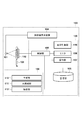
- FIG. 1 is a diagram illustrating a configuration example of a radiation imaging system according to a first embodiment.
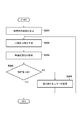
- FIG. 4 is a diagram for explaining the flow of processing in an image processing unit according to the first embodiment.
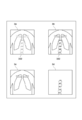
- 3a illustrates a high energy radiation image
- 3b illustrates a low energy radiation image
- 3c illustrates a substance separation image of fat
- 3d illustrates a substance separation image of bone.
- FIG. 4 is a diagram for explaining the effect of the first embodiment. The figure which illustrates the region of interest for which the analysis value of the first embodiment is obtained.
- FIG. 4 is a diagram for explaining the effect of the first embodiment. The figure which illustrates the region of interest for which the analysis value of the first embodiment is obtained.
- FIG. 1 is a diagram illustrating a configuration example of a radiation imaging system 100 according to the first embodiment of the present invention.
- the radiation imaging system 100 includes a radiation generating device 104, a radiation source 101, an FPD 102 (radiation detecting device), and an information processing device 120. Note that the configuration of the radiation imaging system 100 is also simply referred to as a radiation imaging apparatus.
- the information processing device 120 processes information based on a radiographic image of a subject.
- the radiation generator 104 applies a high-voltage pulse to the radiation source 101 by pressing an irradiation switch to generate radiation, and the radiation source 101 irradiates the subject 103 with radiation.
- the type of radiation is not particularly limited, but generally, X-rays can be used.
- the FPD 102 When radiation is applied to the subject 103 from the radiation source 101, the FPD 102 accumulates electric charges based on the image signal and acquires a radiation image. The FPD 102 transfers the radiation image to the information processing device 120. The FPD 102 may transfer the radiographic image to the information processing apparatus 120 for each radiograph, or store the radiographed image in the image storage unit inside the FPD 102 without transmitting the radiograph for each radiograph. It is possible to transfer the images from the FPD 102 to the information processing apparatus 120 at the same time. Communication between the FPD 102 and the information processing device 120 may be wired communication or wireless communication.
- the FPD 102 has a radiation detection unit (not shown) including a pixel array for generating a signal corresponding to radiation.
- the radiation detection unit detects radiation transmitted through the subject 103 as an image signal.
- pixels that output signals according to incident light are arranged in an array (two-dimensional area).
- the photoelectric conversion element of each pixel converts the radiation converted into visible light by the phosphor into an electric signal and outputs the electric signal as an image signal.
- the radiation detection unit is configured to detect the radiation transmitted through the subject 103 and acquire an image signal (radiation image).
- the drive unit of the FPD 102 outputs an image signal (radiation image) read in accordance with an instruction from the control unit 105 to the control unit 105.
- the image processing unit 109 has a generating unit 110, a reconfiguring unit 111, and an analyzing unit 112 as functional components.
- the function of each unit is configured using one or more CPUs (central processing unit) and a program read from the storage unit 108.
- the configuration of each unit of the image processing unit 109 may be configured by an integrated circuit or the like as long as they perform the same function.
- the information processing device 120 may be configured to include a graphic control unit such as a GPU (Graphics Processing Unit), a communication unit such as a network card, an input / output control unit such as a keyboard, a display, or a touch panel. It is possible.
- the monitor 106 displays the radiation image (digital image) received by the control unit 105 from the FPD 102 and the image processed by the image processing unit 109.
- the display control unit 116 can control the display on the monitor 106 (display unit).
- the operation unit 107 can input an instruction to the image processing unit 109 and the FPD 102, and receives an input of an instruction to the FPD 102 via a user interface.
- the generation unit 110 generates material characteristic images for a plurality of substances included in radiation images captured with different radiation energies. That is, a material characteristic image such as a material identification image or a material separation image is generated from the radiation image captured by the FPD 102.
- the substance identification image includes, for a plurality of substances included in the subject, an effective atomic number image indicating an effective atomic number distribution and an area density image indicating an area density distribution.
- the substance separation image includes an image showing the distribution of the thickness or density of each substance when the subject is represented by two or more specific substances.
- the control unit 105 divides low-energy radiation distribution information and high-energy radiation distribution information with a high energy level from a plurality of radiation images obtained by a single radiation irradiation from the radiation generator 104.
- the generation unit 110 When acquired, the generation unit 110 generates a material characteristic image separated into a first substance and a second substance from the low-energy radiation distribution information and the high-energy radiation distribution information based on the acquisition result.
- the generation unit 110 can generate an image indicating the distribution of the thickness or the surface density of a plurality of substances as the substance characteristic image.
- the reconstruction unit 111 sets different radiation energies for a plurality of substances, and generates a reconstructed image based on a monochromatic radiation image for each substance based on the different radiation energies.
- the reconstructing unit 111 obtains a monochromatic radiation image obtained by multiplying the thickness or area density of a substance by an attenuation coefficient (linear attenuation coefficient or mass attenuation coefficient) at different radiation energies, and adds up the multiplication results for each substance. Generate a reconstructed image.
- the analysis unit 112 analyzes the reconstructed image generated by the processing of the reconstructing unit 111, and obtains evaluation information on the contrast of a plurality of substances.
- step S201 the generation unit 110 generates a substance separation image as a substance characteristic image. Specifically, the generation unit 110 calculates the following [Equation 1] from the high-energy radiation image shown in FIG. 3A and the low-energy radiation image shown in FIG. A substance separation image is generated based on the equation (2).
- ⁇ is the linear attenuation coefficient
- d is the thickness of the substance
- the subscripts H and L indicate high energy and low energy, respectively
- the subscripts A and B indicate the substances to be separated (eg, fat and bone). means.
- fat and bone are used as examples of the substance to be separated, but the substance is not particularly limited, and any substance can be used.
- step S202 the reconstructing unit 111 generates a reconstructed radiation image ( Xproc ) from the material separation image, which is the material characteristic image generated in step S201, based on the following [Equation 3].
- a reconstructed radiation image (X proc ) is generated based on the following [Equation 3].
- the reconstructed radiation image ( Xproc ) is also referred to as a reconstructed image or a reconstructed radiation image.
- Reconstruction unit 111 the thickness of the material, different monochromatic radiation image multiplied by the attenuation coefficient (linear attenuation coefficient) in the radiation energy ( ⁇ E1A d A, ⁇ E2B d B) acquires, the result of the multiplication of each substance A reconstructed image (X proc ) is generated by adding them up.
- the contrast of an image increases, but the noise also increases.
- the contrast of the image is reduced and the noise is reduced.
- the substance for a substance (for example, bone) that one wants to see well, the substance is transmitted with low radiation energy so as to absorb more radiation and increase contrast, and the influence of noise in the fat portion around the bone is reduced.
- the standard deviation SD Standard Deviation
- SNR signal-to-noise ratio
- the preset range is changed, and while changing and changing the radiation energies E 1 and E 2 in the changed range, the radiation energy is changed.
- E 1 and radiation energy E 2 may obtain an analysis value converges (optimum value).
- step S204-Yes If the evaluation information (CNR value) has converged in the convergence determination in step S204 (S204-Yes), the process ends. On the other hand, when the convergence determination in step S204 indicates that the evaluation information has not converged (S204-No), the analysis unit 112 advances the processing to step S205.
- step S205 change of the radiation energy E 1, E 2
- the analysis unit 112 changes the radiation energy E 1, E 2.
- the analysis unit 112 sets different radiation energies for each substance so that the evaluation information has the maximum value. For example, one radiation energy (for example, E 1 ) is fixed and the other radiation energy (for example, E 2 ) is changed to a larger single color so that the difference between both radiation energies (E 1 , E 2 ) becomes large. It may be changed to radiation energy.
- the analyzing unit 112 returns the process to step S202.
- step S202 the reconstruction unit 111 generates a reconstructed image ( Xproc ) based on different radiation energies whose settings have been changed. That is, the reconstruction unit 111 acquires the linear attenuation coefficient ⁇ corresponding to the changed radiation energies E 1 and E 2 , and generates a reconstructed image (Xproc) based on Expression 3. Then, in step S203, the analysis unit 112 analyzes the evaluation information based on the generated reconstructed image (Xproc), and the processing in steps 202 to 205 is repeated until it is determined in step S204 that convergence is sufficient. .
- the analysis unit 112 determines whether the evaluation information obtained by the repetitive calculation has converged, and when the evaluation information has converged, the reconstruction unit 111 calculates, for each substance, the radiation energy used in the calculation of the converged evaluation information. Set as different radiation energies. When the analysis results of the evaluation information converge and the radiation energies E 1 and E 2 that are different for each separated substance are finally set, the reconstructing unit 111 sets the lines corresponding to the set radiation energies E 1 and E 2.
- the attenuation coefficient ⁇ is obtained based on the attenuation characteristic information stored in the storage unit 108, a reconstructed image (Xproc) is generated using Expression 3, and is output to the monitor 106 (display unit). .
- the present embodiment it is possible to reconstruct a radiation image by setting radiation energy for each of a plurality of substances without using a tomographic image even in general imaging or fluoroscopic imaging, and to enhance an image of a specific substance. Can be easily obtained.
- the configuration in which the radiation energy is obtained by analysis has been described.
- the values of the radiation energies E 1 and E 2 are stored in advance in a table or the like so as to deal with the separated substances.
- a configuration for shortening the analysis time for determining the radiation energies E 1 and E 2 will be described.
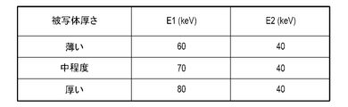
- FIG. 7 is a diagram exemplifying a configuration of a table holding the values of the radiation energies E 1 and E 2 , and the storage unit 108 holds a table in which information on a subject is associated with different radiation energies for each substance. ing.
- the subject information includes information on the body thickness of the subject or information on the thickness of the substance.
- the value of the radiation energy according to the body thickness of the subject is stored as the subject information. If the body thickness of the subject can be obtained, different radiation energies E 1 and E 2 corresponding to the body thickness of the subject can be obtained.
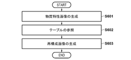
- step S601 the generation unit 110 generates a substance separation image that is a substance characteristic image. This processing is similar to the processing of step S201 of the flowchart described in step S2 of FIG.
- the reconstruction unit 111 sets different radiation energies E 1 and E 2 for each substance corresponding to the information on the subject to be imaged by referring to the table stored in the storage unit 108.
- the body thickness of the subject may be obtained based on the photographing information, may be selected by a technician from the operation unit 107, or may be the thickness of each substance (for example, fat The thickness of the subject may be estimated from the thickness).
- step S603 the reconstructing unit 111 generates a reconstructed image (Xproc) from the material separation image (fat and bone thickness image), which is the material characteristic image generated in step S601, based on [Equation 3].
- the single radiation energies E 1 and E 2 used for generating the reconstructed image (Xproc) are the values set by referring to the table in step S602.
- the display control unit 116 causes the monitor 106 (display unit) to display the reconstructed image (Xproc) generated by the reconstructing unit 111.
- the display control unit 116 displays a reconstructed image (Xproc) and displays a scroll bar on the monitor 106 (display unit) as a user interface (UI) for continuously changing the settings of different radiation energies E 1 and E 2 . .
- UI user interface
- the reconstruction unit 111 acquires attenuation characteristic information corresponding to the radiation energies E 1 and E 2 changed by operating the user interface (scroll bar) with reference to FIG. 4 to generate a reconstructed image (Xproc). Can be.
- the display control unit 116 causes the monitor 106 (display unit) to display a reconstructed image (Xproc) generated based on the changed radiation energy.
- the display control unit 116 can display the value held in the table on the monitor 106 (display unit) as a recommended value.
- the technician can change the value of the radiation energy from the operation unit 107 with reference to the value displayed on the monitor 106 (display unit) so as to emphasize a desired substance.
- the reconstructing unit 111 acquires the line attenuation coefficients corresponding to the radiation energies E 1 and E 2 changed by the input from the operation unit 107 from FIG. 4, generates a reconstructed image (Xproc), and displays the reconstructed image (Xproc).
- the present embodiment by storing the values of the radiation energies E 1 and E 2 in a table in advance, it is possible to generate a good reconstructed radiation image without executing the processing of the optimization method. It becomes.
- a drawing speed of about 15 FPS is required, so that the processing of this embodiment can be applied to processing that requires real-time processing such as during fluoroscopic imaging.
- the present embodiment it is possible to reconstruct a radiation image by setting radiation energy for each of a plurality of substances without using a tomographic image even in general imaging or fluoroscopic imaging, and to enhance an image of a specific substance. Can be easily obtained.
- the third embodiment a configuration in which the values of the radiation energies E 1 and E 2 corresponding to the effective atomic numbers Z 1 and Z 2 are obtained by analysis will be described.
- the configuration example of the radiation imaging system 100 according to the third embodiment of the present invention is the same as the radiation imaging system 100 of FIG. 1 described in the first embodiment, and the radiation imaging system 100 includes a radiation generation device 104 and a radiation source. 101, an FPD 102 (radiation detecting device), and an information processing device 120.
- the description of the same parts as those of the first embodiment will be omitted, and different parts will be described.
- the control unit 105 divides the low-energy radiation distribution information and the high-energy high-energy radiation distribution information from a plurality of radiation images obtained by a single radiation irradiation from the radiation generator 104.
- the generation unit 110 When acquired, the generation unit 110 generates a material characteristic image for a plurality of substances included in the radiation image based on the obtained result.
- the generation unit 110 generates an image (substance separated image) separated into a plurality of substances from the low-energy radiation distribution information and the high-energy radiation distribution information as a substance characteristic image.
- the generation unit 110 can generate an image indicating the thickness or density distribution of a plurality of substances as a separated image (substance separated image).
- the reconstruction unit 111 sets different radiation energies (monochromatic radiation energies) for the positions of a plurality of substances and generates a reconstructed image based on the different radiation energies.
- the position of the substance includes a pixel or a region formed by a plurality of pixels in the radiation image. That is, the reconstruction unit 111 can set different radiation energy for each pixel as the position of the substance. Alternatively, the reconstruction unit 111 can set different radiation energies for each region constituted by a plurality of pixels as the position of the substance.
- the reconstruction unit 111 generates, as a reconstructed image, a monochromatic radiation image obtained by multiplying an attenuation coefficient (mass attenuation coefficient) at radiation energy different for each position of a plurality of substances by a surface density of each pixel.
- the attenuation coefficient is information of a plurality of substances and information associated with radiation energy
- the information of the plurality of substances includes an effective atomic number of the substance or a substance separated into a plurality of substances.
- Information (such as the thickness of the substance).
- the analysis unit 112 creates an energy table that associates a plurality of substances with different radiation energies.
- the analysis unit 112 creates an energy table that associates a single radiation energy with the effective atomic number Zeff i of each pixel as radiation energy (reconstruction energy) used when generating a reconstructed image.
- the reconstruction unit 111 sets different radiation energies for each position of a plurality of substances with reference to the energy table.
- the control unit 105 stores the radiation image captured by the FPD 102 in the storage unit 108 and transfers the radiation image to the image processing unit 109.
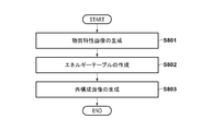
- step S801 the generation unit 110 generates a substance separation image or a substance identification image as a substance characteristic image. Specifically, the generation unit 110 described in the first embodiment a high-energy radiation image as shown in FIG. 3A and a low-energy radiation image as shown in FIG. A substance separation image is generated based on Expression 1 and Expression 2.
- FIG. 9 is a diagram showing the relationship between the logarithmic ratio of the low-energy and high-energy radiation distribution information and the effective atomic number Z. As shown in FIG. 9, the relationship between the logarithmic ratio and the effective atomic number Z is tabulated in advance. And stored in the storage unit 108.
- the generation unit 110 specifies the effective atomic number Z corresponding to the logarithmic ratio for each pixel (the position of a pixel or an area configured by a plurality of pixels) by referring to the table, thereby obtaining the effective atomic number image Z eff . Can be generated.
- the generation unit 110 can generate an area density image D indicating the distribution of the area density of the substance corresponding to the effective atomic number, based on the effective atomic number image Z eff .
- the generation unit 110 replaces the mass attenuation coefficient, the low-energy radiation distribution information ( XL ), and the high-energy radiation, instead of the equations [1] and [2] described in the first embodiment.
- the effective atomic number image Z and the area density image D can be obtained.
- step S802 the analysis unit 112 creates an energy table that associates a plurality of substances with different radiation energies.
- FIG. 11 is a diagram illustrating an energy table that associates an effective atomic number with a single radiation energy.
- the vertical axis indicates radiation energy (E)
- the horizontal axis indicates effective atomic number (Z eff ).
- the effective atomic numbers Z 1 and Z 2 are the effective atomic numbers corresponding to the first ratio (for example, the lower 5%) from the effective atomic numbers in the effective atomic number image, and the effective atomic numbers from the upper one.
- An effective atomic number corresponding to the ratio of 2 (for example, the top 5%) can be used.
- FIG. 13A is a diagram schematically illustrating the relationship between radiation energy and noise
- 13a and 13b in FIG. 13A are diagrams illustrating Comparative Example 1 and Comparative Example 2
- 13c is a diagram illustrating processing according to the present embodiment. is there.
- first substance e.g., bone
- second substance e.g., fat
- CNR ratio of noise to relative contrast
- the analyzing unit 112 sets the information (thickness or density) of each substance after the energy substance separation on the horizontal axis of the energy table, and sets a single radiation energy corresponding to the information of each substance on the vertical axis of the energy table. Should be set to.
- the reconstruction unit 111 refers to the energy table, sets different radiation energies (monochromatic radiation energies) for the positions of the plurality of substances, and generates a reconstructed image based on the different radiation energies.
- the reconstructing unit 111 generates a reconstructed radiation image (X proc ) from the effective atomic number image (Z eff ) and the surface density image (D) generated in step S801 based on the following equation (5).
- the reconstructed radiation image ( Xproc ) is also referred to as a reconstructed image or a reconstructed radiation image.
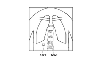
- FIG. 13B is a diagram illustrating the effect of the third embodiment.
- FIG. 13B shows the correspondence (attenuation characteristic information) between the radiation energy and the mass attenuation coefficient
- a waveform 1301 is a waveform indicating an attenuation characteristic of a first substance (for example, bone)
- a waveform 1302 is a waveform.
- 6 is a waveform showing attenuation characteristics of a second substance (for example, fat).
- the attenuation characteristic information differs for each of a plurality of substances (effective atomic numbers).
- a reconstructed radiographic image may be crushed by black or white. Therefore, based on the effective atomic number of each substance, radiation energy is set for each pixel (the position of a pixel or an area constituted by a plurality of pixels) to reconstruct a radiation image. For example, a high energy is set for a pixel indicating an effective atomic number of a second substance (eg, fat), and a low energy is set for a pixel indicating an effective atomic number of a first substance (eg, bone). Is set to generate the reconstructed image (X proc ), it becomes possible to obtain a reconstructed radiographic image in which the first substance is emphasized and the influence of the second substance is reduced.
- a high energy is set for a pixel indicating an effective atomic number of a second substance (eg, fat)
- a low energy is set for a pixel indicating an effective atomic number of a first substance (eg, bone).
- the monitor 106 can display a radiographic image (digital image) received by the control unit 105 from the FPD 102 or an image processed by the image processing unit 109.
- the display control unit 116 causes the monitor 106 (display unit) to display the reconstructed image (X proc ) generated by the reconstructing unit 111.
- the present embodiment it is possible to reconstruct a radiation image by setting different radiation energies for each of the positions of a plurality of substances without using a tomographic image even in general imaging or fluoroscopic imaging. Can be easily obtained.
- the reconstruction unit 111 reconstructs the radiation image (X) based on [Equation 5] from the effective atomic number image (Z eff ) and the surface density image (D) generated in step S801. proc )), but is not limited to this example.
- the reconstruction unit 111 performs the reconfiguration based on the result. It is also possible to generate a composed radiation image (X proc ).
- the energy table 11 when creating the energy table of FIG. 11, the value of the radiation energy E 1, E 2 obtained from the storage unit 108, the energy table 11 based on the radiation energy E 1, E 2 obtained Will be described.
- the configuration of the present embodiment has an advantageous effect when a reconstructed image is generated based on an energy spectrum that a technician wants to emphasize during still image capturing, rather than the real-time property required during fluoroscopic capturing.
- the generation unit 110 generates a material identification image that is a material characteristic image.
- the substance identification image includes, for a plurality of substances included in the subject, an effective atomic number image indicating an effective atomic number distribution and an area density image indicating an area density distribution.
- the analysis unit 112 creates an energy table based on the radiation energies E 1 and E 2 set from the operation unit 107.
- the analysis unit 112 can create an energy table based on radiation energy changed according to imaging information among a plurality of radiation energies set in advance from the operation unit 107.
- the analysis unit 112 calculates the effective atomic numbers Z 1 , Z 2 and the radiation energies E 1 , E 2 based on the radiation energies E 1 , E 2 acquired by referring to the table changed according to the imaging conditions and the like, for example.
- An associated energy table (FIG. 11) is created.
- the reconstruction unit 111 uses the effective atomic number image (Z eff ) and the surface density image (D), which are the material identification images generated in step S801, based on the expression (3) to form the reconstruction image (X proc ).
- the reconstructing unit 111 refers to the energy table (FIG. 11) created in step S802 and converts the effective atomic number Z eff i and the radiation energy E i in each pixel. Generate a reconstructed image (X proc ) based on the corresponding mass attenuation coefficient ⁇ i .
- the effective atomic number of each pixel can be specified based on the effective atomic number image (Z eff )
- the corresponding radiation energy can be set for each pixel position or for each region composed of a plurality of pixels. it can.
- the mass attenuation coefficient ⁇ (Z, E) at the effective atomic number Z and the radiation energy E can be obtained with reference to the table in the storage unit 108.
- the reconstructing unit 111 calculates information on the effective atomic number of the substance and the attenuation coefficient corresponding to the attenuation coefficient corresponding to the radiation energy (mass attenuation coefficient ⁇ (Z, E)) and a plurality of information.
- a reconstructed image (X proc ) is generated based on the area density image D indicating the distribution of the area density of the substance.
- the display control unit 116 causes the monitor 106 (display unit) to display the reconstructed image (X proc ) generated by the reconstructing unit 111.
- the display control unit 116 displays a reconstructed image (X proc ) and also displays a scroll bar on the monitor 106 (display unit) as a user interface (UI) for continuously changing settings of different radiation energies E 1 and E 2. Let it.
- the analysis unit 112 associates different effective atomic numbers Z 1 , Z 2 with the radiation energies E 1 , E 2 based on the radiation energies E 1 , E 2 changed by operating the user interface (scroll bar). (FIG. 11).
- a reconstructed radiation image can be generated based on an energy spectrum that a technician wants to emphasize when capturing a still image.
- the present embodiment it is possible to reconstruct a radiation image by setting different radiation energies for each of the positions of a plurality of substances without using a tomographic image even in general imaging or fluoroscopic imaging. Can be easily obtained.
- 100 radiation imaging system
- 101 radiation source
- 102 FPD (radiation detection device)
- 104 radiation generation device
- 105 control unit
- 106 monitor (display unit)
- 107 operation unit
- 108 storage unit
- 109 Image processing unit
- 110 generation unit
- 112 analysis unit
- 120 information processing device
Abstract
放射線撮影装置(100)は、異なる放射線のエネルギーで撮影した放射線画像に含まれる複数の物質について物質特性画像を生成する生成部(110)と、複数の物質ごとに異なる放射線エネルギーを設定し、異なる放射線エネルギーに基づいた物質ごとの単色放射線画像に基づいて再構成画像を生成する再構成部(111)と、を備える。
Description
本発明は、放射線撮影装置、放射線撮影方法およびプログラムに関するものである。
放射線による医療画像診断に用いる撮影装置として、平面検出器(Flat Panel Detector、以下「FPD」と略す)を用いた放射線撮影装置が普及している。FPDは、撮影画像をデジタル画像処理することができるため、例えば医療画像診断においては、一般撮影のような静止画撮影や、透視撮影のような動画撮影のデジタル撮影装置やCT装置として用いられている。
特許文献1には、CT装置において、2種類の管電圧を用いて被写体を撮影するデュアルエネルギースキャンという手法を適用して物質の同定を行い、物質ごとに適切な放射線エネルギーを用いて放射線画像を生成する構成が開示されている。
しかし、放射線エネルギーの減弱特性は物質ごとに異なるため、断層画像が得られない一般撮影や透視撮影では、放射線のビームライン上に存在している複数の物質ごとに放射線エネルギーを設定して放射線画像を再構成することが必要とされる。
本発明は、複数の物質ごとに異なる放射線エネルギーを設定して放射線画像を再構成することが可能な放射線撮影技術を提供する。
本発明の一態様による放射線撮影装置は以下の構成を備える。すなわち、放射線撮影装置は、異なる放射線のエネルギーで撮影した放射線画像に含まれる複数の物質について物質特性画像を生成する生成手段と、
前記複数の物質ごとに異なる放射線エネルギーを設定し、前記異なる放射線エネルギーに基づいた物質ごとの単色放射線画像に基づいて再構成画像を生成する再構成手段と、
を備えることを特徴とする。
前記複数の物質ごとに異なる放射線エネルギーを設定し、前記異なる放射線エネルギーに基づいた物質ごとの単色放射線画像に基づいて再構成画像を生成する再構成手段と、
を備えることを特徴とする。
本発明の他の態様による放射線撮影装置は以下の構成を備える。すなわち、放射線撮影装置は、放射線発生手段からの単一の放射線照射によって得られた複数の放射線画像から低エネルギーの放射線分布情報と、エネルギーレベルの高い高エネルギーの放射線分布情報とを取得する取得手段と、
前記低エネルギーの放射線分布情報および前記高エネルギーの放射線分布情報から第一の物質と第二の物質とに分離した物質特性画像を生成する生成手段と、
前記第一の物質に対応する第一の放射線エネルギーに基づく単色放射線画像と、前記第二の物質に対応する第二の放射線エネルギーに基づく単色放射線画像と、に基づいて再構成画像を生成する再構成手段と、を備えることを特徴とする。
前記低エネルギーの放射線分布情報および前記高エネルギーの放射線分布情報から第一の物質と第二の物質とに分離した物質特性画像を生成する生成手段と、
前記第一の物質に対応する第一の放射線エネルギーに基づく単色放射線画像と、前記第二の物質に対応する第二の放射線エネルギーに基づく単色放射線画像と、に基づいて再構成画像を生成する再構成手段と、を備えることを特徴とする。
本発明によれば、複数の物質ごとに異なる放射線エネルギーを設定して放射線画像を再構成することが可能になる。
本発明のその他の特徴及び利点は、添付図面を参照とした以下の説明により明らかになるであろう。なお、添付図面においては、同じ若しくは同様の構成には、同じ参照番号を付す。
添付図面は明細書に含まれ、その一部を構成し、本発明の実施の形態を示し、その記述と共に本発明の原理を説明するために用いられる。
第1実施形態に係る放射線撮影システムの構成例を示す図。
第1実施形態の画像処理部における処理の流れを説明する図。
3aは高エネルギー放射線画像を例示する図、3bは低エネルギー放射線画像を例示する図、3cは脂肪の物質分離画像を例示する図、3dは骨の物質分離画像を例示する図。
第1実施形態の効果を説明する図。
第1実施形態の解析値を求める関心領域を例示する図。
第2実施形態の画像処理部における処理の流れを説明する図。
第2実施形態の放射線エネルギーを決定するテーブルを例示する図。
第3実施形態の画像処理部における処理の流れを説明する図。
低エネルギー及び高エネルギーの放射線分布情報の対数比と、実効原子番号Zの関係を示す図。
物質の実効原子番号を例示する図。
実効原子番号と単一の放射線エネルギーとを対応付けるエネルギーテーブルを例示する図。
放射線画像における関心領域を例示する図。
放射線エネルギーとノイズの関係を模式的に示す図。
第3実施形態の効果を説明する図である。
以下、図面を参照して、本発明の実施形態を例示的に詳しく説明する。ただし、この実施形態に記載されている構成要素はあくまで例示であり、本発明の技術的範囲は、特許請求の範囲によって確定されるのであって、以下の個別の実施形態によって限定されるわけではない。
(第1実施形態)
図1は、本発明の第1実施形態に係る放射線撮影システム100の構成例を示す図である。放射線撮影システム100は、放射線発生装置104、放射線源101、FPD102(放射線検出装置)、情報処理装置120を有する。尚、放射線撮影システム100の構成を単に放射線撮影装置ともいう。情報処理装置120は、被写体を撮影した放射線画像に基づく情報を処理する。
図1は、本発明の第1実施形態に係る放射線撮影システム100の構成例を示す図である。放射線撮影システム100は、放射線発生装置104、放射線源101、FPD102(放射線検出装置)、情報処理装置120を有する。尚、放射線撮影システム100の構成を単に放射線撮影装置ともいう。情報処理装置120は、被写体を撮影した放射線画像に基づく情報を処理する。
放射線発生装置104は照射スイッチの押下により放射線源101に高電圧パルスを与え放射線を発生させ、放射線源101は被写体103に放射線を照射する。放射線の種類は特に限定はしないが、一般的にはX線を用いることが可能である。
放射線源101から放射線が被写体103に照射されると、FPD102は画像信号に基づく電荷の蓄積を行って放射線画像を取得する。FPD102は、放射線画像を情報処理装置120に転送する。尚、FPD102は、撮影毎に放射線画像を情報処理装置120に転送してもよいし、撮影した画像を、撮影毎に転送せずに、FPD102の内部の画像記憶部に記憶しておき、所定のタイミングでFPD102から情報処理装置120に画像を、まとめて転送することが可能である。FPD102と情報処理装置120との間の通信は、有線通信でもよいし、無線通信でもよい。
FPD102は、放射線に応じた信号を生成するための画素アレイを備えた放射線検出部(不図示)を有する。放射線検出部は、被写体103を透過した放射線を画像信号として検出する。放射線検出部には、入射光に応じた信号を出力する画素がアレイ状(二次元の領域)に配置されている。各画素の光電変換素子は蛍光体により可視光に変換された放射線を電気信号に変換し、画像信号として出力する。このように、放射線検出部は被写体103を透過した放射線を検出して、画像信号(放射線画像)を取得するように構成されている。FPD102の駆動部は、制御部105からの指示に従って読み出した画像信号(放射線画像)を制御部105に出力する。
制御部105は、FPD102から取得した放射線画像を処理する画像処理部109と、画像処理の結果や各種プログラムを記憶する記憶部108とを有する。記憶部108は、例えば、ROM(Read Only Memory)、RAM(Random Access Memory)等により構成される。記憶部108は制御部105から出力された画像や画像処理部109で画像処理された画像、画像処理部109における計算結果を記憶することが可能である。
画像処理部109は、機能構成として、生成部110、再構成部111、解析部112を有している。これらの機能構成は、例えば、一つ又は複数のCPU(central processing unit)、記憶部108から読み込んだプログラムを用いて、各部の機能が構成される。画像処理部109の各部の構成は、同様の機能を果たすのであれば、それらは集積回路などで構成してもよい。また、情報処理装置120の内部構成として、GPU(Graphics Processing Unit)等のグラフィック制御部、ネットワークカード等の通信部、キーボード、ディスプレイ又はタッチパネル等の入出力制御部等を含むように構成することが可能である。
モニタ106(表示部)は、制御部105がFPD102から受信した放射線画像(デジタル画像)や画像処理部109で画像処理された画像を表示する。表示制御部116は、モニタ106(表示部)の表示を制御することが可能である。操作部107は、画像処理部109やFPD102に対する指示を入力することができ、ユーザーインターフェイスを介してFPD102に対する指示の入力を受け付ける。
制御部105は、被写体に照射する放射線のエネルギーが異なる複数の放射線画像を処理することによって新たな画像(例えば、骨画像および脂肪画像)を得るエネルギーサブトラクション法を用いた撮影制御を行うことが可能である。エネルギーサブトラクション法による撮影を実施する場合、1枚のサブトラクション画像を生成するために異なる放射線エネルギーで撮影された少なくとも2枚の放射線画像が必要となる。FPD102は、1回の放射線照射に対して複数回のサンプリングを行う。これにより、FPD102は、低エネルギーの放射線による画像(低エネルギー放射線画像)と高エネルギーの放射線による画像(高エネルギー放射線画像)を1回の放射線照射で取得できる。FPD102による撮影は静止画撮影または動画撮影であってもよい。
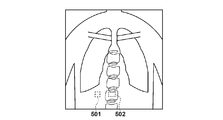
FPD102内に一時保存された放射線分布情報は、サンプリングホールド実施後、読み出し可能となり、制御部105は、FPD102から異なるタイミングで、放射線分布情報(XL)と放射線分布情報(XL+XH)の読み出しを実施する。制御部105は、放射線分布情報(XL+XH)から放射線分布情報(XL)を差し引くことで、放射線分布情報(XH)を得ることができる。ここで、低エネルギーの放射線分布情報(XL)が低エネルギー放射線画像の基の画像になり、高エネルギーの放射線分布情報(XH)が高エネルギー放射線画像の基の画像になる。図3の3aは高エネルギー放射線画像を例示する図であり、図3の3bは低エネルギー放射線画像を例示する図である。図3の3bの低エネルギー放射線画像の骨部302は、図3の3aの高エネルギー放射線画像の骨部301に比べて、コントラストが明確に表示されている。
画像処理部109は、機能構成として、生成部110、再構成部111、解析部112を有している。生成部110は、異なる放射線のエネルギーで撮影した放射線画像に含まれる複数の物質を抽出することが可能である。また、生成部110は、異なる放射線エネルギーによる複数の放射線画像を用いて複数の物質特性画像を生成することが可能である。
生成部110は、異なる放射線のエネルギーで撮影した放射線画像に含まれる複数の物質について物質特性画像を生成する。すなわち、FPD102で撮影された放射線画像から、物質識別画像や物質分離画像などの物質特性画像を生成する。物質識別画像には、被写体に含まれる複数の物質について、実効原子番号の分布を示す実効原子番号画像と、面密度の分布を示す面密度画像とが含まれる。また、物質分離画像には、被写体を特定の2以上の物質で表した場合に、各物質の厚さ又は密度の分布を示す画像が含まれる。
ここで、実効原子番号とは、元素、化合物、混合物の元素を平均的に見た場合に相当する原子番号を示し、その構成物質と同じ割合で光子の減弱をする仮想の元素の原子番号を示す定量指標である。実効原子番号画像とは画素を単位として、被写体を単一の構成物質で表した場合に相当する原子番号で構成された画像をいう。生成部110は、FPD102で撮影された放射線画像から、実効原子番号画像といった物質特性画像を生成することが可能である。
エネルギーサブトラクション法により、制御部105が、放射線発生装置104からの単一の放射線照射によって得られた複数の放射線画像から低エネルギーの放射線分布情報と、エネルギーレベルの高い高エネルギーの放射線分布情報とを取得すると、この取得結果に基づいて、生成部110は、低エネルギーの放射線分布情報および高エネルギーの放射線分布情報から第一の物質と第二の物質とに分離した物質特性画像を生成する。
生成部110は、物質特性画像として複数の物質の厚さ、または面密度の分布を示す画像を生成することが可能である。
また、再構成部111は、複数の物質ごとに異なる放射線エネルギーを設定し、異なる放射線エネルギーに基づいた物質ごとの単色放射線画像に基づいて再構成画像を生成する。
例えば、複数の物質として、第一の物質と第二の物質に分離された場合、再構成部111は、第一の物質に対応する第一の放射線エネルギーに基づく単色放射線画像と、第二の物質に対応する第二の放射線エネルギーに基づく単色放射線画像と、に基づいて再構成画像を生成する。
再構成部111は、物質の厚さ又は面密度に、異なる放射線エネルギーにおける減弱係数(線減弱係数又は質量減弱係数)を乗じた単色放射線画像を取得し、物質ごとの乗算結果を足し合わせることにより再構成画像を生成する。
解析部112は、再構成部111の処理により生成された再構成画像を解析し、複数の物質のコントラストに関する評価情報を取得する。
次に、第1実施形態の画像処理部109における処理を、図2に示すフローチャートを用いて詳細に説明する。制御部105は、FPD102で撮影された放射線画像を記憶部108に記憶するとともに、画像処理部109に放射線画像を転送する。
(S201:物質特性画像の生成)
ステップS201において、生成部110は、物質特性画像として物質分離画像を生成する。具体的には、生成部110は、FPD102で撮影された図3の3aに示すような高エネルギー放射線画像と図3の3bに示すような低エネルギー放射線画像から以下の[数1]式、[数2]式に基づいて物質分離画像を生成する。
ステップS201において、生成部110は、物質特性画像として物質分離画像を生成する。具体的には、生成部110は、FPD102で撮影された図3の3aに示すような高エネルギー放射線画像と図3の3bに示すような低エネルギー放射線画像から以下の[数1]式、[数2]式に基づいて物質分離画像を生成する。
ここで、XLは低エネルギーの放射線分布情報であり、低エネルギーの放射線分布情報(XL)が低エネルギー放射線画像の基の画像になる。また、XHは高エネルギーの放射線分布情報であり、高エネルギーの放射線分布情報(XH)が高エネルギー放射線画像の基の画像になる。以下、低エネルギー放射線画像を低エネルギー放射線画像XLとして表記し、高エネルギー放射線画像を高エネルギー放射線画像XHとして表記する。
μは線減弱係数、dは物質の厚さであり、添え字のHとLはそれぞれ高エネルギーと低エネルギーを示し、添え字のAとBはそれぞれ分離する物質(例えば、脂肪と骨)を意味する。なお、ここでは、分離する物質の例として、脂肪と骨を物質例として用いるが、特に限定するものでなく任意の物質を用いることができる。
本実施形態において、制御部105は、放射線源101からの単一の放射線照射によってFPD102(放射線検出装置)が撮影した複数の放射線画像(XL、XH)を取得する取得部として機能する。制御部105(取得部)は、FPD102(放射線検出装置)が撮影した複数の放射線画像を、異なる放射線エネルギーによる複数の放射線画像として取得する。生成部110は、制御部105(取得部)が取得した複数の放射線画像(XL、XH)に基づいて、複数の物質特性画像を生成する。
生成部110は、[数1]式と[数2]式の連立方程式を解く演算処理を行うことにより、各物質に分離した物質分離画像を得ることができる。図3の3cは脂肪の厚さdAに基づいて取得した物質分離画像を例示する図であり、図3の3dは骨の厚さdBに基づいて取得した物質分離画像を例示する図である。
(S202:再構成画像の生成)
ステップS202において、再構成部111は、ステップS201で生成した物質特性画像である物質分離画像から以下の[数3]式に基づいて、再構成した放射線画像(Xproc)を生成する。例えば、分離した物質が、脂肪及び骨である場合、再構成部111は、脂肪の厚さdAに基づいて取得した物質分離画像、及び骨の厚さdBに基づいて取得した物質分離画像から以下の[数3]式に基づいて、再構成した放射線画像(Xproc)を生成する。以下、再構成した放射線画像(Xproc)を再構成画像、または再構成放射線画像ともいう。
ステップS202において、再構成部111は、ステップS201で生成した物質特性画像である物質分離画像から以下の[数3]式に基づいて、再構成した放射線画像(Xproc)を生成する。例えば、分離した物質が、脂肪及び骨である場合、再構成部111は、脂肪の厚さdAに基づいて取得した物質分離画像、及び骨の厚さdBに基づいて取得した物質分離画像から以下の[数3]式に基づいて、再構成した放射線画像(Xproc)を生成する。以下、再構成した放射線画像(Xproc)を再構成画像、または再構成放射線画像ともいう。
ここで、Eは再構成画像(Xproc)の生成に用いる単一の放射線エネルギーあり、E1とE2は異なる放射線エネルギーであることを示す。dは物質の厚さであり、添え字のAとBはそれぞれ分離した物質(脂肪と骨)を示す。μは線減弱係数であり、μE1Aは放射線エネルギーE1Aに対応した線減弱係数であり、μE2Bは放射線エネルギーE2Bに対応した線減弱係数である。再構成部111は、物質の厚さに、異なる放射線エネルギーにおける減弱係数(線減弱係数)を乗じた単色放射線画像(μE1AdA、μE2BdB)を取得し、物質ごとの乗算結果を足し合わせることにより再構成画像(Xproc)を生成する。
図4は、第1実施形態の効果を説明する図である。図4には、放射線エネルギーと線減弱係数との対応関係(減弱特性情報)が示されており、波形401は骨の減弱特性を示す波形であり、波形402は脂肪の減弱特性を示す波形である。記憶部108は、放射線エネルギーと減弱係数(線減弱係数、質量減弱係数)との対応関係を示す減弱特性情報を記憶する。複数の物質ごとに減弱特性情報は異なる。例えば、図4の波形401、402に示すように、複数の物質ごとに減弱特性情報は異なるものとなる。
一般的に、低い放射線エネルギーで物質を透過させると、画像のコントラストは上がるが、ノイズも大きくなる。一方、より高い放射線エネルギーで物質を透過させると、画像のコントラストは下がり、ノイズも小さくなる。図4に示すように、よく見たい物質(例えば、骨)については、より放射線を吸収してコントラストを上げるように低い放射線エネルギーで物質を透過させ、骨の周りの脂肪部分のノイズの影響を低減するように、より高い放射線エネルギーで物質を透過させることで、分離した画像間における相対的なコントラストを向上させることができる。
例えば、脂肪と骨を100keVの単色放射線で画像化(再構成)した場合、骨と脂肪との間の相対的なコントラストはコントラスト1で示される。一方、本実施形態の処理により、物質ごとに放射線エネルギーを設定して放射線画像を再構成する場合、例えば、脂肪に対する放射線エネルギーをE1=100keVとし、骨に対する放射線エネルギーをE2=30keVとした単色放射線で画像化(再構成)する場合、骨と脂肪との間の相対的なコントラストはコントラスト2で示され、分離した脂肪と骨のコントラストがつきやすくなる。
人体の大部分は脂肪で構成されているため、軟物質である脂肪の厚さが厚く、放射線吸収が強すぎると、再構成した放射線画像の黒潰れや白潰れを生じさせてしまう。そこで、物質ごとに放射線エネルギーを設定して放射線画像を再構成する。すなわち、脂肪に対しては高エネルギーを設定し、骨に対しては低エネルギーを設定して再構成画像(Xproc)を生成することで、脂肪の厚さの影響を低減した再構成放射線画を取得することが可能になる。
例えば、コントラストの下限となる値(基準値)を設定した場合、再構成部111は、図4に示すような減弱特性情報に基づいて、複数の物質のコントラストが予め設定された基準値より大きくなるように、物質ごとに異なる放射線エネルギーを設定することが可能である。また、コントラストの上限となる値は、以下に説明する再構成放射線画像の解析に基づいた繰り返し計算によるシミュレーションにより、解析結果が収束したときの値となる。
尚、本実施形態では、再構成部111は、ステップS201で生成した物質特性画像である物質分離画像から[数3]式に基づいて、再構成した放射線画像(Xproc)を生成しているが、この例に限定されない。例えば、生成部110が異なる放射線のエネルギーで撮影した放射線画像に含まれる複数の物質を抽出し、抽出した物質の情報を[数3]式に適用した結果に基づいて、再構成部111は再構成した放射線画像(Xproc)を生成することも可能である。
(S203:再構成放射線画像の解析)
ステップS203において、解析部112は、再構成した放射線画像を解析し評価情報を取得する。解析部112は、ステップS202で生成した再構成画像(Xproc)を解析する。ここで、再構成画像(Xproc)の解析のための評価情報として、以下の[数4]式に示す情報を用いることができる。評価情報として以下の[数4]式では、複数の物質の関心領域間のコントラストと、複数の物質のうちいずれか一方の物質の関心領域における画素値の標準偏差と、の比(コントラスト雑音比)として取得されるCNR(Contrast to Noise Ratio)を用いるが、この他に標準偏差SD(Standard Deviation)や、分離した物質について、複数の物質の関心領域における画素値の平均値を差分することにより取得されるコントラスト(MA-MB)、SN比(SNR:signal-to-noise ratio)等を評価情報として用いることも可能である。
ステップS203において、解析部112は、再構成した放射線画像を解析し評価情報を取得する。解析部112は、ステップS202で生成した再構成画像(Xproc)を解析する。ここで、再構成画像(Xproc)の解析のための評価情報として、以下の[数4]式に示す情報を用いることができる。評価情報として以下の[数4]式では、複数の物質の関心領域間のコントラストと、複数の物質のうちいずれか一方の物質の関心領域における画素値の標準偏差と、の比(コントラスト雑音比)として取得されるCNR(Contrast to Noise Ratio)を用いるが、この他に標準偏差SD(Standard Deviation)や、分離した物質について、複数の物質の関心領域における画素値の平均値を差分することにより取得されるコントラスト(MA-MB)、SN比(SNR:signal-to-noise ratio)等を評価情報として用いることも可能である。
CNRは、複数の物質の関心領域における画素値の平均値を差分することにより取得されるコントラスト(MA-MB)と、複数の物質のうちいずれか一方の物質の関心領域における画素値の標準偏差(SD値)と、の比として取得される。
ここで、Mは図5に示す関心領域における画素値の平均値であり、SDは関心領域における画素値の標準偏差(SD値)である。添え字Aは脂肪の関心領域501の値を示し、MAは脂肪の関心領域における画素値の平均値を示す。SDAは脂肪の関心領域における画素値の標準偏差を示す。また、添え字Bは骨の関心領域502の値を示し、MBは骨の関心領域における画素値の平均値を示す。関心領域の設定方法は事前に指定しても良いし、解析処理の実行開始の際に技師が操作部107の操作により関心領域を設定することも可能である。
(S204:解析値の収束判定)
ステップS204において、解析部112は、CNRが収束した解析値(最適値)になっているかどうか判定する。再構成放射線画像を生成する[数3]式において、放射線エネルギーを示すE1、E2は未知の量であるため、初期値を定め微小変化させながら、分離した物質毎に任意の単一放射線エネルギーに基づいた再構成画像(Xproc)を[数3]式により生成し、[数4]式の評価関数に基づいて、CNRの最適値を求めることになる。
ステップS204において、解析部112は、CNRが収束した解析値(最適値)になっているかどうか判定する。再構成放射線画像を生成する[数3]式において、放射線エネルギーを示すE1、E2は未知の量であるため、初期値を定め微小変化させながら、分離した物質毎に任意の単一放射線エネルギーに基づいた再構成画像(Xproc)を[数3]式により生成し、[数4]式の評価関数に基づいて、CNRの最適値を求めることになる。
解析値の収束判定処理として、解析部112は、最初の計算で取得した評価情報(CNRの値)を記憶部108に記憶する。そして、解析部112は、2回目以降の繰り返し計算で取得した評価情報(CNRの値)について収束判定を行う。解析部112は、例えば、n+1回目(n≧1の整数)の繰り返し計算で取得した評価情報と、記憶部108に記憶しているn回目の計算に基づく評価情報とを比較する。具体的には、2回目の繰り返し計算で取得した評価情報と、記憶部108に記憶している1回目の計算に基づく評価情報とを比較する。あるいは、3回目の繰り返し計算で取得した評価情報と、記憶部108に記憶している2回目の計算に基づく評価情報とを比較する。
最適化方法には、例えば、二分法、勾配法、ニュートン法等種々の非線形最適化手法を用いることができる。収束判定は所定の回数を設定してもよいし、放射線エネルギーの微小変化量ΔE刻みで、放射線エネルギーE1、E2を変化させながら、放射線エネルギーE1,E2の組み合わせの総当たりで評価情報を算出し、放射線エネルギーE1及び放射線エネルギーE2が収束する解析値(最適値)を取得しても良い。例えば、一般の放射線機器の場合、放射線エネルギーE1、E2の取りうる範囲は20keV~200keV程度となるため、プリセット範囲としてこの範囲で放射線エネルギーE1、E2を変化させることが可能である。また、それ以外の範囲で再構成画像(Xproc)を生成することも可能であるため、プリセット範囲を変更し、変更後の範囲で放射線エネルギーE1、E2を変化させ変化させながら、放射線エネルギーE1及び放射線エネルギーE2が収束する解析値(最適値)を取得しても良い。
あるいは、[数4]式の評価情報(CNRの値)が繰り返し計算により変動しなくなった時点を設定してもよい。例えば、比較結果により得られる評価情報の差分または評価情報の変化率が収束判定の基準値以下となる場合、解析部112は、評価情報が収束したと判定することが可能である。
ステップS204の収束判定で、評価情報(CNRの値)が収束した場合(S204-Yes)、処理を終了する。一方、ステップS204の収束判定で、評価情報が収束していない場合(S204-No)、解析部112は、処理をステップS205に進める。
(S205:放射線エネルギーE1、E2の変更)
ステップS204で解析値の収束が十分でないと判定された場合、ステップS205において、解析部112は放射線エネルギーE1、E2を変更する。解析部112は、評価情報が最大値となるように、物質ごとに異なる放射線エネルギーを設定する。例えば、両方の放射線エネルギー(E1、E2)の差分が大きくなるように、一方の放射線エネルギー(例えば、E1)を固定し、他方の放射線エネルギー(例えば、E2)を、より大きな単色放射線エネルギーに変更してもよい。解析部112は放射線エネルギーを変更した後、処理をステップS202に戻す。
ステップS204で解析値の収束が十分でないと判定された場合、ステップS205において、解析部112は放射線エネルギーE1、E2を変更する。解析部112は、評価情報が最大値となるように、物質ごとに異なる放射線エネルギーを設定する。例えば、両方の放射線エネルギー(E1、E2)の差分が大きくなるように、一方の放射線エネルギー(例えば、E1)を固定し、他方の放射線エネルギー(例えば、E2)を、より大きな単色放射線エネルギーに変更してもよい。解析部112は放射線エネルギーを変更した後、処理をステップS202に戻す。
ステップS202において、再構成部111は、設定を変更した異なる放射線エネルギーに基づいて再構成画像(Xproc)を生成する。すなわち、再構成部111は、変更された放射線エネルギーE1、E2に対応する線減弱係数μを取得し、[数3]式に基づいて、再構成画像(Xproc)を生成する。そして、ステップS203で、解析部112は、生成された再構成画像(Xproc)に基づいて評価情報を解析し、ステップS204で収束が十分と判定されるまでステップ202~ステップ205の処理が繰り返される。
解析部112は、繰り返し計算により取得した評価情報が収束したか判定し、評価情報が収束した場合、再構成部111は、収束した評価情報の計算の際に用いた放射線エネルギーを、物質ごとに異なる放射線エネルギーとして設定する。評価情報の解析結果が収束し、分離した物質ごとに異なる放射線エネルギーE1、E2が最終的に設定されると、再構成部111は、設定した放射線エネルギーE1、E2に対応する線減弱係数μを、記憶部108に記憶されている減弱特性情報に基づいて取得し、[数3]式を用いて、再構成画像(Xproc)を生成し、モニタ106(表示部)に出力する。
モニタ106(表示部)は、制御部105がFPD102から受信した放射線画像(デジタル画像)や画像処理部109で画像処理された画像を表示することが可能である。表示制御部116は、再構成部111により生成された再構成画像(Xproc)をモニタ106(表示部)に表示させる。また、表示制御部116は、再構成画像(Xproc)と、物質特性画像である物質分離画像とを並べてモニタ106(表示部)に表示させるよう表示制御を行うことも可能である。また、表示制御部116は、モニタ106(表示部)に表示されている画像から技師により選択された少なくとも一つの画像を表示部に表示させるよう表示制御を行うことも可能である。
本実施形態によれば、一般撮影や透視撮影であっても、断層画像を用いることなく、複数の物質ごとに放射線エネルギーを設定して放射線画像を再構成することができ、特定物質の強調画像を簡便に取得するが可能となる。
(第2実施形態)
第1実施形態では解析により放射線エネルギーを求める構成を説明したが、本実施形態では、放射線エネルギーE1、E2の値をテーブルなどで事前に保持しておくことで、分離した物質に対応する放射線エネルギーE1、E2を決定する解析時間を短縮する構成について説明する。
第1実施形態では解析により放射線エネルギーを求める構成を説明したが、本実施形態では、放射線エネルギーE1、E2の値をテーブルなどで事前に保持しておくことで、分離した物質に対応する放射線エネルギーE1、E2を決定する解析時間を短縮する構成について説明する。
以下の説明では、第1実施形態と同様の部分は重複を避けるために説明を省略し、第2実施形態に特有な構成部分についてのみ説明を行う。本実施形態の構成は、透視撮影時などのリアルタイム性が要求される場合に有利な効果がある。
図7は放射線エネルギーE1、E2の値を保持するテーブルの構成を例示する図であり、記憶部108は、被写体の情報と、物質ごとに異なる放射線エネルギーとを対応づけたテーブルを保持している。被写体の情報には、被写体の体厚の情報または物質の厚さの情報が含まれる。図7に示すテーブルには、被写体の情報として、被写体の体厚に応じて放射線エネルギーの値が保持されている。被写体の体厚を求めることができれば、被写体の体厚に対応した、異なる放射線エネルギーE1、E2を取得することができる。
第2実施形態の画像処理部109における処理を、図6に示すフローチャートを用いて詳細に説明する。まず、ステップS601において、生成部110は、物質特性画像である物質分離画像を生成する。この処理は図2のステップS2で説明したフローチャートのステップS201の処理と同様の処理となる。
ステップS602において、再構成部111は、記憶部108に記憶されているテーブルの参照により、撮影対象の被写体の情報に対応する、物質ごとに異なる放射線エネルギーE1、E2を設定する。被写体の体厚は、撮影情報に基づいて被写体の体厚を取得してもよいし、技師が操作部107から選択しても良いし、物質分離画像における各物質の厚さ(例えば、脂肪の厚さ)から被写体の体厚を推定してもよい。
ステップS603において、再構成部111は、ステップS601で生成した物質特性画像である物質分離画像(脂肪と骨の厚み画像)から[数3]式に基づいて、再構成画像(Xproc)を生成する。ここで、再構成画像(Xproc)の生成に用いる単一の放射線エネルギーE1、E2はステップS602においてテーブルの参照により設定した値である。
表示制御部116は、再構成部111により生成された再構成画像(Xproc)をモニタ106(表示部)に表示させる。表示制御部116は、再構成画像(Xproc)の表示とともに、異なる放射線エネルギーE1、E2の設定を連続的に変更するユーザインタフェース(UI)としてスクロールバーをモニタ106(表示部)に表示させる。スクロールバーを技師が操作することにより、放射線エネルギーE1、E2を連続的に変更することができる。再構成部111は、ユーザーインターフェイス(スクロールバー)の操作により変更された放射線エネルギーE1、E2に対応する減弱特性情報を図4の参照により取得して再構成画像(Xproc)を生成することができる。表示制御部116は、変更された放射線エネルギーに基づいて生成された再構成画像(Xproc)をモニタ106(表示部)に表示させる。
技師は、放射線エネルギーE1、E2の値を連続的に変化させながら、変化に対応して生成される再構成画像(Xproc)の変化を観察することができる。例えば、骨成分の減弱を強めていく場合(放射線エネルギーを低く設定する場合)に、強調される病変であれば、骨に関わる病変であることがわかる。これにより病変が脂肪成分に依存した病変であるのか骨成分に依存した病変であるのかを見分けることが可能になる。
また、ステップS602において、表示制御部116は、テーブルに保持されている値を推奨値としてモニタ106(表示部)に表示させることも可能である。技師はモニタ106(表示部)に表示された値を参照して、見たい物質を強調するように、放射線エネルギーの値を操作部107から変更することが可能である。再構成部111は、操作部107からの入力により変更された放射線エネルギーE1、E2に対応する線減弱係数を図4から取得して再構成画像(Xproc)を生成し、表示制御部116は、変更された放射線エネルギーに基づいて生成された再構成画像(Xproc)をモニタ106(表示部)に表示させる。
本実施形態によれば、事前に放射線エネルギーE1、E2の値をテーブルに保持しておくことで、最適化手法の処理を実行することなく良好な再構成放射線画像を生成することが可能となる。透視撮影では、例えば、15FPS程度の描画速度が求められるため、本実施形態の処理は透視撮影時などのリアルタイム性が要求される処理においても本実施形態の処理を適用することが可能である。
本実施形態によれば、一般撮影や透視撮影であっても、断層画像を用いることなく、複数の物質ごとに放射線エネルギーを設定して放射線画像を再構成することができ、特定物質の強調画像を簡便に取得するが可能となる。
(第3実施形態)
第3実施形態では解析により、実効原子番号Z1、Z2に対応する放射線エネルギーE1、E2の値を求める構成を説明する。本発明の第3実施形態に係る放射線撮影システム100の構成例は、第1実施形態で説明した図1の放射線撮影システム100と同様であり、放射線撮影システム100は、放射線発生装置104、放射線源101、FPD102(放射線検出装置)、情報処理装置120を有する。第1実施形態の構成と重複する部分については説明を省略し、相違する部分について説明する。
第3実施形態では解析により、実効原子番号Z1、Z2に対応する放射線エネルギーE1、E2の値を求める構成を説明する。本発明の第3実施形態に係る放射線撮影システム100の構成例は、第1実施形態で説明した図1の放射線撮影システム100と同様であり、放射線撮影システム100は、放射線発生装置104、放射線源101、FPD102(放射線検出装置)、情報処理装置120を有する。第1実施形態の構成と重複する部分については説明を省略し、相違する部分について説明する。
エネルギーサブトラクション法により、制御部105が、放射線発生装置104からの単一の放射線照射によって得られた複数の放射線画像から低エネルギーの放射線分布情報と、エネルギーレベルの高い高エネルギーの放射線分布情報とを取得すると、この取得結果に基づいて、生成部110は、放射線画像に含まれる複数の物質について物質特性画像を生成する。生成部110は、低エネルギーの放射線分布情報および高エネルギーの放射線分布情報から複数の物質に分離した画像(物質分離画像)を物質特性画像として生成する。生成部110は、分離した画像(物質分離画像)として複数の物質の厚さ、または密度の分布を示す画像を生成することが可能である。
また、生成部110は、低エネルギーの放射線分布情報および前記高エネルギーの放射線分布情報から複数の物質の分布を示す画像(物質識別画像)を物質特性画像として生成する。生成部110は、複数の物質の分布を示す画像(物質識別画像)として複数の物質の実効原子番号の分布を示す画像、または物質の面密度の分布を示す面密度画像を生成することが可能である。
また、再構成部111は、複数の物質の位置ごとに異なる放射線エネルギー(単色の放射線エネルギー)を設定し、異なる放射線エネルギーに基づいて再構成画像を生成する。ここで、物質の位置としては、放射線画像における画素または複数の画素により構成される領域が含まれる。すなわち、再構成部111は、物質の位置として画素ごとに、異なる放射線エネルギーを設定することが可能である。あるいは、再構成部111は、物質の位置として複数の画素により構成される領域ごとに、異なる放射線エネルギーを設定することが可能である。
具体的な処理として、再構成部111は、複数の物質の位置ごとに異なる放射線エネルギーにおける減弱係数(質量減弱係数)に各画素の面密度を乗じた単色放射線画像を再構成画像として生成する。ここで、減弱係数(質量減弱係数)は、複数の物質の情報及び放射線エネルギーに対応づけられた情報であり、複数の物質の情報には、物質の実効原子番号又は複数の物質に分離した物質の情報(物質の厚さ等)が含まれる。
解析部112は、複数の物質と異なる放射線エネルギーとを対応付けるエネルギーテーブルを作成する。解析部112は、再構成画像を生成する際に使用する放射線エネルギー(再構成エネルギー)として、各画素の実効原子番号Zeff iに対する単一の放射線エネルギーを対応付けたエネルギーテーブルを作成する。再構成部111は、エネルギーテーブルを参照して、複数の物質の位置ごとに異なる放射線エネルギーを設定する。
次に、第3実施形態の画像処理部109における処理を、図8に示すフローチャートを用いて詳細に説明する。制御部105は、FPD102で撮影された放射線画像を記憶部108に記憶するとともに、画像処理部109に放射線画像を転送する。
(S801:物質特性画像の生成)
ステップS801において、生成部110は、物質特性画像として物質分離画像、または物質識別画像を生成する。具体的には、生成部110は、FPD102で撮影された図3の3aに示すような高エネルギー放射線画像と図3の3bに示すような低エネルギー放射線画像から、第1実施形態で説明した[数1]式、[数2]式に基づいて物質分離画像を生成する。
ステップS801において、生成部110は、物質特性画像として物質分離画像、または物質識別画像を生成する。具体的には、生成部110は、FPD102で撮影された図3の3aに示すような高エネルギー放射線画像と図3の3bに示すような低エネルギー放射線画像から、第1実施形態で説明した[数1]式、[数2]式に基づいて物質分離画像を生成する。
本実施形態において、生成部110は、低エネルギーの放射線分布情報(XL)と高エネルギーの放射線分布情報(XH)との対数比(lnXL/lnXH)を取得して、取得した対数比に基づいて、実効原子番号画像Zeffを生成する。図9は低エネルギー及び高エネルギーの放射線分布情報の対数比と、実効原子番号Zの関係を示す図であり、予め図9に示すような、対数比と実効原子番号Zの関係をテーブル化しておき、記憶部108に記憶しておく。生成部110は、テーブルの参照により、対数比に対応する実効原子番号Zを、画素(画素の位置、または複数の画素により構成される領域)ごとに特定することにより実効原子番号画像Zeffを生成することができる。生成部110は、実効原子番号画像Zeffに基づいて、実効原子番号に対応する物質の面密度の分布を示す面密度画像Dを生成することができる。
図10は、物質の実効原子番号を例示する図である。例えば、脂肪の実効原子番号は5.9~6.5であり、水の実効原子番号は7.4である。また、筋肉の実効原子番号は7.4~7.6であり、骨の実効原子番号は12.3~13.8である。このように、脂肪、水、筋肉、骨など、人体(被写体)を構成する特定の領域を実効原子番号により特定することができる。
造影剤などに含まれるヨウ素の実効原子番号は53であり、バリウムの実効原子番号は56であり、カテーテルのガイドワイヤ等に用いられる部材としてステンレスの実効原子番号は26である。また、ステントに用いられる部材として、チタンの実効原子番号は22である。実効原子番号の情報を用いることにより、撮影手技に応じて人体(被写体)の内部に入っている物質を識別することができる。
尚、生成部110は、第1実施形態で説明した[数1]式及び[数2]式の代わりに、質量減弱係数と、低エネルギーの放射線分布情報(XL)と、高エネルギーの放射線分布情報(XH)とに基づいた連立方程式を解くことにより実効原子番号画像Z及び面密度画像Dを取得することも可能である。
(S802:エネルギーテーブルの作成)
ステップS802において、解析部112は、複数の物質と異なる放射線エネルギーとを対応付けるエネルギーテーブルを作成する。
ステップS802において、解析部112は、複数の物質と異なる放射線エネルギーとを対応付けるエネルギーテーブルを作成する。
図11は、実効原子番号と単一の放射線エネルギーとを対応付けるエネルギーテーブルを例示する図である。図11において、縦軸は放射線エネルギー(E)を示し、横軸は実効原子番号(Zeff)を示す。実効原子番号のZ1、Z2はヒストグラム解析を用いて、実効原子番号画像における実効原子番号のうち、下位から第1の割合(例えば、下位5%)に相当する実効原子番号、上位から第2の割合(例えば、上位5%)に相当する実効原子番号とすることができる。
図12は、放射線画像における関心領域を例示する図である。図12に示すように、放射線画像に対する画像処理により部位認識を行い、第一の物質(例えば、脂肪)や第二の物質(例えば、骨)や第三の物質(例えば、カテーテルやステントなどの医療デバイス)を抽出し、対応する物質の実効原子番号の値を、エネルギーテーブルにおける実効原子番号としてもよい。例えば、第一の物質(例えば、脂肪)の関心領域1201における実効原子番号の平均値をZ1とし、第二の物質(例えば、骨)の関心領域1202における実効原子番号の平均値をZ2としてもよい。
実効原子番号Z1、Z2に対応付ける放射線エネルギーは、複数の物質に対応する画素の実効原子番号や複数の物質に対応する関心領域1201、1202における実効原子番号の平均値を用いて最適化して求めてもよい。図13Aは、放射線エネルギーとノイズの関係を模式的に示す図であり、図13Aの13a、13bは比較例1、比較例2を示す図であり、13cは本実施形態の処理を示す図である。
図13Aの13a(比較例1)に示すように、一般的に、低い放射線エネルギーE2で第一の物質及び第二の物質を透過させると、第一の物質及び第二の物質の画像のコントラストは全体的に上がるが、ノイズも全体的に大きくなる。一方、13b(比較例2)に示すように、より高い放射線エネルギーE1で第一の物質及び第二の物質の画像を透過させると、第一の物質及び第二の物質の画像のコントラストは下がり、ノイズも小さくなる。図13Aの13a、13bに示すように、画像間のコントラストに対するノイズの割合(CNR)は、ほぼ一定となる。
本実施形態では、図13Aの13cに示すように、よく見たい第一の物質(例えば、骨)については、より放射線を吸収してコントラストを上げるように低い放射線エネルギーE2で物質を透過させ、骨の周りの第二の物質(例えば、脂肪)のノイズの影響を低減するように、より高い放射線エネルギーE1で物質を透過させることで、異なる物質の画素、または、異なる物質の領域ごとに異なる放射線エネルギーを設定することで、第一の物質の画像及び第二の物質の画像間における相対的なコントラストに対するノイズの割合(CNR)を向上させるものである。
再構成放射線画像を生成する、以下の[数5]式において、実効原子番号に対応する放射線エネルギーは未知の量であるため、各放射線エネルギーの初期値を定め、放射線エネルギーの微小変化量ΔE刻みで、放射線エネルギーを変化させながら、再構成部111は、設定を段階的に変更した異なる放射線エネルギーに基づいて再構成画像(Xproc)を[数5]式により順次生成し、解析部112は、再構成画像(Xproc)を解析し、複数の物質のコントラストに関する評価情報を取得する。
評価情報には、複数の物質に対応する各領域における画素値の平均値を差分することにより取得されるコントラストが含まれる。また、評価情報には、複数の物質に対応する領域間におけるコントラストと、複数の物質のうちいずれか一方の物質に対応する領域における画素値の標準偏差と、の比(コントラスト雑音比)として取得されるCNR(Contrast to Noise Ratio)が含まれる。また、標準偏差SD(Standard Deviation)や、SN比(SNR:signal-to-noise ratio)等を評価情報として用いることも可能である。解析部112は、評価情報が最大値となるように、物質ごとに異なる放射線エネルギー(E1、E2)を設定する。
図11に示すエネルギーテーブルの作成において、実効原子番号の設定Z1、Z2を既知の情報に基づいて予め設定しておくことも可能である。例えば、脂肪の実効原子番号や骨の実効原子番号は、既知であるので、これらの実効原子番号をプリセットとしてもよい。
また、図11に示すエネルギーテーブルの作成において、放射線エネルギーE1(実効原子番号Z1)と、放射線エネルギーE2(実効原子番号Z2)との間を線形補間しているが、対数補間やシグモイド関数で補間してもよい。更に、図11では、実効原子番号Z1以下の値、実効原子番号Z2以上の値はアーチファクト防止のため一定値としているが、線形補間等で外挿してもよい。
実効原子番号Z1、Z2に対応付ける放射線エネルギーE1、E2は、一般的な放射線撮影装置の場合、20keV~200keV程度となるため、プリセット範囲としてこの範囲で放射線エネルギーE1、E2を設定することが可能である。また、それ以外の範囲で放射線エネルギーE1、E2を設定することも可能である。ここでは、実効原子番号画像を例に用いて説明したが、第1実施形態で説明した[数1]式、[数2]式に基づいて取得した物質分離後の各物質の情報(厚さまたは密度)と、再構成する時の単一の放射線エネルギーとを対応付けることで同様の処理を行うことも可能である。この場合、解析部112は、エネルギー物質分離後の各物質の情報(厚さまたは密度)をエネルギーテーブルの横軸に設定し、各物質の情報に対応付ける単一の放射線エネルギーをエネルギーテーブルの縦軸に設定すればよい。
(S803:再構成画像の生成)
ステップS803において、再構成部111は、エネルギーテーブルを参照して、複数の物質の位置ごとに異なる放射線エネルギー(単色の放射線エネルギー)を設定し、異なる放射線エネルギーに基づいて再構成画像を生成する。再構成部111は、ステップS801で生成した実効原子番号画像(Zeff)と面密度画像(D)から以下の[数5]式に基づいて、再構成した放射線画像(Xproc)を生成する。以下、再構成した放射線画像(Xproc)を再構成画像、または再構成放射線画像ともいう。
ステップS803において、再構成部111は、エネルギーテーブルを参照して、複数の物質の位置ごとに異なる放射線エネルギー(単色の放射線エネルギー)を設定し、異なる放射線エネルギーに基づいて再構成画像を生成する。再構成部111は、ステップS801で生成した実効原子番号画像(Zeff)と面密度画像(D)から以下の[数5]式に基づいて、再構成した放射線画像(Xproc)を生成する。以下、再構成した放射線画像(Xproc)を再構成画像、または再構成放射線画像ともいう。
ここで、Eは再構成画像(Xproc)の生成に用いる単一の放射線エネルギーあり、添え字iは画素を示す。Diは各画素の面密度を示す。μiは質量減弱係数であり、質量減弱係数μiは各画素における実効原子番号Zeff iと、放射線エネルギーEiとに対応する。各画素の実効原子番号と、放射線エネルギーとの対応関係は、例えば、図11のようなエネルギーテーブルにより対応付けられており、実効原子番号画像(Zeff)に基づいて、各画素の実効原子番号を特定することができれば、対応する放射線エネルギーを画素の位置、または複数の画素により構成される領域ごとに設定することができる。
記憶部108には、物質の実効原子番号及び放射線エネルギーに対応する減弱係数の情報(質量減弱係数μ(Z,E))を保持するテーブルが記憶されている。実効原子番号Z及び放射線エネルギーEにおける質量減弱係数μ(Z,E)をテーブル化して記憶部108に記憶しておくことにより、再構成部111は、テーブルの参照により、質量減弱係数μ(Z,E)を取得することができる。
[数5]式に基づいて、再構成部111は、物質の実効原子番号及び放射線エネルギーに対応する減弱係数に対応する減弱係数の情報(質量減弱係数μ(Z,E))と、複数の物質の面密度の分布を示す面密度画像Dとに基づいて、再構成画像(Xproc)を生成する。
図13Bは、第3実施形態の効果を説明する図である。図13Bには、放射線エネルギーと質量減弱係数との対応関係(減弱特性情報)が示されており、波形1301は第一の物質(例えば、骨)の減弱特性を示す波形であり、波形1302は第二の物質(例えば、脂肪)の減弱特性を示す波形である。図13Bの波形1301、1302に示すように、複数の物質(実効原子番号)ごとに減弱特性情報は異なるものとなる。
例えば、脂肪と骨を100keVの単色放射線で画像化(再構成)した場合、骨と脂肪との間の相対的なコントラストはコントラスト1で示される。一方、物質の位置(画素、または領域)ごとに放射線エネルギーを設定して放射線画像を再構成する場合、例えば、第二の物質(例えば、脂肪)の画素に対する放射線エネルギーを100keVとし、第一の物質(例えば、骨)の画素に対する放射線エネルギーを30keVとした単色放射線で画像化(再構成)する場合、骨の画素と脂肪の画素との間の相対的なコントラストはコントラスト2で示され、脂肪と骨の画素間でコントラストがつきやすくなる。
人体の大部分は脂肪で構成されているため、軟物質である脂肪の厚さが厚く、放射線吸収が強すぎると、再構成した放射線画像の黒潰れや白潰れを生じさせてしまう。そこで、各物質の実効原子番号に基づいて、画素(画素の位置、または複数の画素により構成される領域)ごとに放射線エネルギーを設定して放射線画像を再構成する。例えば、第二の物質(例えば、脂肪)の実効原子番号を示す画素に対しては高エネルギーを設定し、第一の物質(例えば、骨)の実効原子番号を示す画素に対しては低エネルギーを設定して再構成画像(Xproc)を生成することで、第一の物質を強調し、第二の物質の影響を低減した再構成放射線画を取得することが可能になる。
モニタ106(表示部)は、制御部105がFPD102から受信した放射線画像(デジタル画像)や画像処理部109で画像処理された画像を表示することが可能である。表示制御部116は、再構成部111により生成された再構成画像(Xproc)をモニタ106(表示部)に表示させる。
本実施形態によれば、一般撮影や透視撮影であっても、断層画像を用いることなく、複数の物質の位置ごとに異なる放射線エネルギーを設定して放射線画像を再構成することができ、特定物質の強調画像を簡便に取得するが可能となる。
尚、本実施形態では、再構成部111は、ステップS801で生成した実効原子番号画像(Zeff)と面密度画像(D)から[数5]式に基づいて、再構成した放射線画像(Xproc)を生成しているが、この例に限定されない。例えば、生成部110が異なる放射線のエネルギーで撮影した放射線画像に含まれる複数の物質を抽出し、抽出した物質の情報を[数5]式に適用した結果に基づいて、再構成部111は再構成した放射線画像(Xproc)を生成することも可能である。
(第4実施形態)
第3実施形態では解析により、実効原子番号Z1、Z2に対応する放射線エネルギーE1、E2の値を求める構成を説明したが、本実施形態では、技師が操作部107を操作して放射線エネルギーE1、E2の値を設定したエネルギーテーブルを事前に記憶部108に保持しておく構成について説明する。
第3実施形態では解析により、実効原子番号Z1、Z2に対応する放射線エネルギーE1、E2の値を求める構成を説明したが、本実施形態では、技師が操作部107を操作して放射線エネルギーE1、E2の値を設定したエネルギーテーブルを事前に記憶部108に保持しておく構成について説明する。
本実施形態では、図11のエネルギーテーブルを作成する際に、放射線エネルギーE1、E2の値を記憶部108から取得し、取得した放射線エネルギーE1、E2に基づいて図11のエネルギーテーブルを作成する構成について説明する。
以下の説明では、第3実施形態と同様の部分は重複を避けるために説明を省略し、第4実施形態に特有な構成部分についてのみ説明を行う。本実施形態の構成は、透視撮影時に要求されるリアルタイム性よりも、静止画撮影時に技師が強調したいエネルギースペクトルに基づいて再構成画像を生成する場合に有利な効果がある。
第4実施形態の画像処理部109における処理を、図8のフローチャートを用いて詳細に説明する。まず、ステップS801において、生成部110は、物質特性画像である物質識別画像を生成する。ここで、物質識別画像には、被写体に含まれる複数の物質について、実効原子番号の分布を示す実効原子番号画像と、面密度の分布を示す面密度画像とが含まれる。
ステップS802において、解析部112は、記憶部108に記憶されているテーブルの参照により、設定されている放射線エネルギーE1、E2を取得する。放射線エネルギーE1、E2の値は技師が操作部107から任意に設定することが可能であり、例えば、被写体の撮影部位や被写体の体格などの撮影情報に応じて、放射線エネルギーE1、E2を保持した複数種類のテーブルを記憶部108に記憶しておくことが可能である。
解析部112は、操作部107から設定された放射線エネルギーE1、E2に基づいて、エネルギーテーブルを作成する。また、解析部112は、操作部107から予め設定された複数の放射線エネルギーのうち撮影情報に応じて変更した放射線エネルギーに基づいて、エネルギーテーブルを作成することが可能である。解析部112は、例えば、撮影条件等に応じて変更したテーブルの参照により取得した放射線エネルギーE1、E2に基づいて、実効原子番号Z1、Z2と放射線エネルギーE1、E2とを対応付けたエネルギーテーブル(図11)を作成する。
ステップS803において、再構成部111は、ステップS801で生成した物質識別画像である実効原子番号画像(Zeff)と面密度画像(D)から[数3]式に基づいて、再構成画像(Xproc)を生成する。再構成画像(Xproc)の生成において、再構成部111は、ステップS802で作成したエネルギーテーブル(図11)を参照して、各画素における実効原子番号Zeff iと、放射線エネルギーEiとに対応する質量減弱係数μiに基づいて、再構成画像(Xproc)を生成する。
実効原子番号画像(Zeff)に基づいて、各画素の実効原子番号を特定することができれば、対応する放射線エネルギーを、画素の位置、または複数の画素により構成される領域ごとに設定することができる。
実効原子番号Z及び放射線エネルギーEが決まれば、記憶部108のテーブルを参照して、実効原子番号Z及び放射線エネルギーEにおける質量減弱係数μ(Z,E)を取得することができる。
[数3]式に基づいて、再構成部111は、物質の実効原子番号及び放射線エネルギーに対応する減弱係数に対応する減弱係数の情報(質量減弱係数μ(Z,E))と、複数の物質の面密度の分布を示す面密度画像Dとに基づいて、再構成画像(Xproc)を生成する。
表示制御部116は、再構成部111により生成された再構成画像(Xproc)をモニタ106(表示部)に表示させる。表示制御部116は、再構成画像(Xproc)の表示とともに、異なる放射線エネルギーE1、E2の設定を連続的に変更するユーザインタフェース(UI)としてスクロールバーをモニタ106(表示部)に表示させる。
スクロールバーを技師が操作することにより、放射線エネルギーE1、E2を連続的に変更することができる。解析部112は、ユーザーインターフェイス(スクロールバー)の操作により変更された放射線エネルギーE1、E2に基づいて、異なる実効原子番号Z1、Z2と放射線エネルギーE1、E2とを対応付けるエネルギーテーブル(図11)を作成する。
再構成部111は、変更された放射線エネルギーE1、E2に基づいて生成されたエネルギーテーブルの参照により、質量減弱係数μ(Z,E)を取得することができ、再構成部111は、取得した質量減弱係数μ(Z,E)と、複数の物質の面密度の分布を示す面密度画像Dとに基づいて、再構成画像(Xproc)を生成することが可能である。
技師は、放射線エネルギーE1、E2の値を連続的に変化させながら、変化に対応して生成される再構成画像(Xproc)の変化を観察することができる。例えば、骨成分の減弱を強めていく場合(放射線エネルギーを低く設定する場合)に、強調される病変であれば、骨に関わる病変であることがわかる。これにより病変が脂肪成分に依存した病変であるのか骨成分に依存した病変であるのかを見分けることが可能になる。
本実施形態によれば、事前に放射線エネルギーE1、E2の値をテーブルに保持しておくことで、最適化手法の処理を実行することなく良好な再構成放射線画像を生成することが可能となる。例えば、静止画撮影時に技師が強調したいエネルギースペクトルに基づいて再構成放射線画像を生成することができる。
本実施形態によれば、一般撮影や透視撮影であっても、断層画像を用いることなく、複数の物質の位置ごとに異なる放射線エネルギーを設定して放射線画像を再構成することができ、特定物質の強調画像を簡便に取得するが可能となる。
(その他の実施形態)
本発明は、上述の実施形態の1以上の機能を実現するプログラムを、ネットワーク又は記憶媒体を介してシステム又は装置に供給し、そのシステム又は装置のコンピュータにおける1つ以上のプロセッサーがプログラムを読出し実行する処理でも実現可能である。また、1以上の機能を実現する回路(例えば、ASIC)によっても実現可能である。
本発明は、上述の実施形態の1以上の機能を実現するプログラムを、ネットワーク又は記憶媒体を介してシステム又は装置に供給し、そのシステム又は装置のコンピュータにおける1つ以上のプロセッサーがプログラムを読出し実行する処理でも実現可能である。また、1以上の機能を実現する回路(例えば、ASIC)によっても実現可能である。
本発明は上記実施の形態に制限されるものではなく、本発明の精神及び範囲から離脱することなく、様々な変更及び変形が可能である。従って、本発明の範囲を公にするために、以下の請求項を添付する。
本願は、2018年6月27日提出の日本国特許出願特願2018-122352及び特願2018-122354を基礎として優先権を主張するものであり、その記載内容の全てを、ここに援用する。
100:放射線撮影システム、101:放射線源、102:FPD(放射線検出装置)、104:放射線発生装置、105:制御部、106:モニタ(表示部)、107:操作部、108:記憶部、109:画像処理部、110:生成部、111 再構成部、112:解析部、120:情報処理装置
Claims (26)
- 異なる放射線のエネルギーで撮影した放射線画像に含まれる複数の物質について物質特性画像を生成する生成手段と、
前記複数の物質ごとに異なる放射線エネルギーを設定し、前記異なる放射線エネルギーに基づいた物質ごとの単色放射線画像に基づいて再構成画像を生成する再構成手段と、
を備えることを特徴とする放射線撮影装置。 - 放射線発生手段からの単一の放射線照射によって得られた複数の放射線画像から低エネルギーの放射線分布情報と、エネルギーレベルの高い高エネルギーの放射線分布情報とを取得する取得手段と、
前記低エネルギーの放射線分布情報および前記高エネルギーの放射線分布情報から第一の物質と第二の物質とに分離した物質特性画像を生成する生成手段と、
前記第一の物質に対応する第一の放射線エネルギーに基づく単色放射線画像と、前記第二の物質に対応する第二の放射線エネルギーに基づく単色放射線画像と、に基づいて再構成画像を生成する再構成手段と、
を備えることを特徴とする放射線撮影装置。 - 前記生成手段は、前記物質特性画像として前記複数の物質の厚さ、または面密度の分布を示す画像を生成することを特徴とする請求項1または2に記載の放射線撮影装置。
- 前記再構成手段は、前記物質の厚さ又は面密度に、異なる放射線エネルギーにおける減弱係数を乗じた単色放射線画像を取得し、物質ごとの乗算結果を足し合わせることにより前記再構成画像を生成することを特徴とする請求項3に記載の放射線撮影装置。
- 前記生成手段は、前記複数の放射線画像についてエネルギーサブトラクションを行った結果に基づいて前記複数の物質の物質特性画像を生成することを特徴とする請求項1乃至3のいずれか1項に記載の放射線撮影装置。
- 放射線エネルギーと減弱係数との対応関係を示す減弱特性情報を記憶する記憶手段を更に備え、前記複数の物質ごとに減弱特性情報は異なることを特徴とする請求項1に記載の放射線撮影装置。
- 前記再構成手段は、前記減弱特性情報に基づいて、前記複数の物質のコントラストが設定された基準値より大きくなるように、前記物質ごとに異なる放射線エネルギーを設定することを特徴とする請求項6に記載の放射線撮影装置。
- 前記再構成画像を解析し、前記複数の物質のコントラストに関する評価情報を取得する解析手段を更に備えることを特徴とする請求項1に記載の放射線撮影装置。
- 前記評価情報には、前記複数の物質の関心領域における画素値の平均値を差分することにより取得されるコントラストが含まれることを特徴とする請求項8に記載の放射線撮影装置。
- 前記評価情報には、前記コントラストと、前記複数の物質のうちいずれか一方の物質の関心領域における画素値の標準偏差と、の比として取得されるCNR(Contrast to Noise Ratio)が含まれることを特徴とする請求項9に記載の放射線撮影装置。
- 前記解析手段は、前記評価情報が最大値となるように、前記物質ごとに異なる放射線エネルギーを設定することを特徴とする請求項8乃至10のいずれか1項に記載の放射線撮影装置。
- 前記再構成手段は、設定を変更した異なる放射線エネルギーに基づいて前記再構成画像を生成し、前記解析手段は、前記再構成画像に基づいて前記評価情報を繰り返し計算することを特徴とする請求項8乃至11のいずれか1項に記載の放射線撮影装置。
- 前記解析手段は、前記繰り返し計算により取得した前記評価情報が収束したか判定し、
前記評価情報が収束した場合、前記再構成手段は、当該収束した評価情報の計算の際に用いた放射線エネルギーを、前記物質ごとに異なる放射線エネルギーとして決定することを特徴とする請求項12に記載の放射線撮影装置。 - 放射線発生手段からの単一の放射線照射によって放射線検出装置が撮影した複数の放射線画像を取得する取得手段を更に備えることを特徴とする請求項1に記載の放射線撮影装置。
- 前記取得手段は、前記放射線検出装置が撮影した複数の放射線画像を、前記異なる放射線エネルギーによる複数の放射線画像として取得し、
前記生成手段は、前記取得手段が取得した複数の放射線画像に基づいて、前記複数の物質特性画像を生成することを特徴とする請求項14に記載の放射線撮影装置。 - 前記記憶手段は、被写体の情報と、物質ごとに異なる放射線エネルギーとを対応づけたテーブルを保持し、
前記再構成手段は、前記テーブルの参照により、撮影対象の前記被写体の情報に対応する、前記物質ごとに異なる放射線エネルギーを設定することを特徴とする請求項6に記載の放射線撮影装置。 - 前記被写体の情報には、前記被写体の体厚の情報または前記物質の厚さの情報が含まれることを特徴とする請求項16に記載の放射線撮影装置。
- 異なる放射線のエネルギーで撮影した放射線画像に含まれる複数の物質を抽出する抽出手段と、
前記複数の物質ごとに異なる放射線エネルギーを設定し、前記異なる放射線エネルギーに基づいた物質ごとの単色放射線画像に基づいて再構成画像を生成する再構成手段と、
を備えることを特徴とする放射線撮影装置。 - 前記再構成画像を表示手段に表示させる表示制御手段を更に備え、
前記表示制御手段は、前記再構成画像の表示とともに、異なる放射線エネルギーの設定を連続的に変更するユーザーインターフェイスを前記表示手段に表示させることを特徴とする請求項1乃至18のいずれか1項に記載の放射線撮影装置。 - 異なる放射線のエネルギーで撮影した放射線画像に含まれる複数の物質について物質特性画像を生成する生成手段と、
前記複数の物質の位置ごとに異なる放射線エネルギーを設定し、前記異なる放射線エネルギーに基づいて再構成画像を生成する再構成手段と、
を備えることを特徴とする放射線撮影装置。 - 異なる放射線のエネルギーで撮影した放射線画像に含まれる複数の物質を抽出する抽出手段と、
前記複数の物質の位置ごとに異なる放射線エネルギーを設定し、前記異なる放射線エネルギーに基づいて再構成画像を生成する再構成手段と、
を備えることを特徴とする放射線撮影装置。 - 放射線撮影装置による放射線撮影方法であって、
異なる放射線のエネルギーで撮影した放射線画像に含まれる複数の物質について物質特性画像を生成する生成工程と、
前記複数の物質ごとに異なる放射線エネルギーを設定し、前記異なる放射線エネルギーに基づいた物質ごとの単色放射線画像に基づいて再構成画像を生成する再構成工程と、
を有することを特徴とする放射線撮影方法。 - 放射線撮影装置による放射線撮影方法であって、
異なる放射線のエネルギーで撮影した放射線画像に含まれる複数の物質を抽出する抽出工程と、
前記複数の物質ごとに異なる放射線エネルギーを設定し、前記異なる放射線エネルギーに基づいた物質ごとの単色放射線画像に基づいて再構成画像を生成する再構成工程と、
を有することを特徴とする放射線撮影方法。 - 放射線撮影装置による放射線撮影方法であって、
異なる放射線のエネルギーで撮影した放射線画像に含まれる複数の物質について物質特性画像を生成する生成工程と、
前記複数の物質の位置ごとに異なる放射線エネルギーを設定し、前記異なる放射線エネルギーに基づいて再構成画像を生成する再構成工程と、
を有することを特徴とする放射線撮影方法。 - 放射線撮影装置による放射線撮影方法であって、
異なる放射線のエネルギーで撮影した放射線画像に含まれる複数の物質を抽出する抽出工程と、
前記複数の物質の位置ごとに異なる放射線エネルギーを設定し、前記異なる放射線エネルギーに基づいて再構成画像を生成する再構成工程と、
を有することを特徴とする放射線撮影方法。 - コンピュータに、請求項22乃至25のいずれか1項に記載の放射線撮影方法の各工程を実行させるためのプログラム。
Priority Applications (1)
| Application Number | Priority Date | Filing Date | Title |
|---|---|---|---|
| US17/127,302 US11813095B2 (en) | 2018-06-27 | 2020-12-18 | Radiation imaging apparatus, radiation imaging method, and non-transitory computer-readable storage medium |
Applications Claiming Priority (4)
| Application Number | Priority Date | Filing Date | Title |
|---|---|---|---|
| JP2018122354A JP7144988B2 (ja) | 2018-06-27 | 2018-06-27 | 放射線撮影装置、放射線撮影方法およびプログラム |
| JP2018-122354 | 2018-06-27 | ||
| JP2018-122352 | 2018-06-27 | ||
| JP2018122352A JP7144987B2 (ja) | 2018-06-27 | 2018-06-27 | 放射線撮影装置、放射線撮影方法およびプログラム |
Related Child Applications (1)
| Application Number | Title | Priority Date | Filing Date |
|---|---|---|---|
| US17/127,302 Continuation US11813095B2 (en) | 2018-06-27 | 2020-12-18 | Radiation imaging apparatus, radiation imaging method, and non-transitory computer-readable storage medium |
Publications (1)
| Publication Number | Publication Date |
|---|---|
| WO2020003744A1 true WO2020003744A1 (ja) | 2020-01-02 |
Family
ID=68985616
Family Applications (1)
| Application Number | Title | Priority Date | Filing Date |
|---|---|---|---|
| PCT/JP2019/018337 WO2020003744A1 (ja) | 2018-06-27 | 2019-05-08 | 放射線撮影装置、放射線撮影方法およびプログラム |
Country Status (2)
| Country | Link |
|---|---|
| US (1) | US11813095B2 (ja) |
| WO (1) | WO2020003744A1 (ja) |
Families Citing this family (1)
| Publication number | Priority date | Publication date | Assignee | Title |
|---|---|---|---|---|
| JP7169853B2 (ja) | 2018-11-09 | 2022-11-11 | キヤノン株式会社 | 画像処理装置、放射線撮影装置、および画像処理方法 |
Citations (4)
| Publication number | Priority date | Publication date | Assignee | Title |
|---|---|---|---|---|
| JP2011172803A (ja) * | 2010-02-25 | 2011-09-08 | Ge Medical Systems Global Technology Co Llc | X線ct装置 |
| JP2014061286A (ja) * | 2012-08-30 | 2014-04-10 | Toshiba Corp | X線ct装置、画像処理装置、及び画像処理方法 |
| WO2016147844A1 (ja) * | 2015-03-19 | 2016-09-22 | 株式会社日立製作所 | X線ct装置及びマルチエネルギー像作成方法 |
| JP2016193921A (ja) * | 2010-07-12 | 2016-11-17 | ジーイー・ヘルスケア・アクスイェ・セルスカプ | 低造影剤濃度及び/又は低放射線量でのx線イメージング |
Family Cites Families (53)
| Publication number | Priority date | Publication date | Assignee | Title |
|---|---|---|---|---|
| US8115784B2 (en) * | 2008-11-26 | 2012-02-14 | General Electric Company | Systems and methods for displaying multi-energy data |
| JP5315157B2 (ja) | 2009-07-27 | 2013-10-16 | キヤノン株式会社 | 情報処理装置、ライン状ノイズ低減処理方法、及びプログラム |
| JP5543194B2 (ja) | 2009-12-24 | 2014-07-09 | キヤノン株式会社 | 情報処理装置、処理方法及びプログラム |
| JP6214128B2 (ja) | 2010-11-22 | 2017-10-18 | キヤノン株式会社 | 画像処理装置、画像処理方法、及び記憶媒体 |
| JP5725930B2 (ja) | 2011-03-31 | 2015-05-27 | ジーイー・メディカル・システムズ・グローバル・テクノロジー・カンパニー・エルエルシー | 画像生成装置およびx線ct装置並びにプログラム |
| JP5814621B2 (ja) | 2011-05-24 | 2015-11-17 | キヤノン株式会社 | 撮像装置及びその制御方法、並びに、撮像システム |
| JP6073616B2 (ja) * | 2011-09-28 | 2017-02-01 | 東芝メディカルシステムズ株式会社 | X線ct装置、画像処理装置及びプログラム |
| JP6122269B2 (ja) | 2011-12-16 | 2017-04-26 | キヤノン株式会社 | 画像処理装置、画像処理方法、及びプログラム |
| JP5950840B2 (ja) | 2012-03-16 | 2016-07-13 | キヤノン株式会社 | 放射線撮像装置及び撮像システム |
| JP5986526B2 (ja) | 2012-04-06 | 2016-09-06 | キヤノン株式会社 | 放射線撮像装置、その制御方法及び放射線撮像システム |
| JP6162937B2 (ja) | 2012-08-31 | 2017-07-12 | キヤノン株式会社 | 放射線撮像装置、その制御方法および制御プログラム |
| JP6312401B2 (ja) | 2012-11-30 | 2018-04-18 | キヤノン株式会社 | 画像処理装置、画像処理方法、及びプログラム |
| JP6041669B2 (ja) | 2012-12-28 | 2016-12-14 | キヤノン株式会社 | 撮像装置及び撮像システム |
| JP6016673B2 (ja) | 2013-02-28 | 2016-10-26 | キヤノン株式会社 | 放射線撮像装置および放射線撮像システム |
| JP2014168205A (ja) | 2013-02-28 | 2014-09-11 | Canon Inc | 放射線撮像装置、放射線検査装置、信号の補正方法およびプログラム |
| JP5934128B2 (ja) | 2013-02-28 | 2016-06-15 | キヤノン株式会社 | 放射線撮像装置及び放射線撮像システム |
| JP5986524B2 (ja) | 2013-02-28 | 2016-09-06 | キヤノン株式会社 | 放射線撮像装置および放射線撮像システム |
| JP6161346B2 (ja) | 2013-03-19 | 2017-07-12 | キヤノン株式会社 | 撮像システム |
| US20140361189A1 (en) | 2013-06-05 | 2014-12-11 | Canon Kabushiki Kaisha | Radiation imaging system |
| JP6238577B2 (ja) | 2013-06-05 | 2017-11-29 | キヤノン株式会社 | 放射線撮像装置及び放射線撮像システム |
| JP6376783B2 (ja) | 2014-03-12 | 2018-08-22 | キヤノン株式会社 | 乳房断層撮影装置および制御方法 |
| JP6355387B2 (ja) | 2014-03-31 | 2018-07-11 | キヤノン株式会社 | 撮像装置及び撮像システム |
| US9737271B2 (en) | 2014-04-09 | 2017-08-22 | Canon Kabushiki Kaisha | Radiation imaging apparatus and control method of the same |
| JP6362421B2 (ja) | 2014-05-26 | 2018-07-25 | キヤノン株式会社 | 放射線撮像装置、その制御方法およびプログラム |
| JP6494204B2 (ja) | 2014-07-17 | 2019-04-03 | キヤノン株式会社 | 放射線撮像装置及び放射線撮像システム |
| JP6385179B2 (ja) | 2014-07-18 | 2018-09-05 | キヤノン株式会社 | 放射線撮像装置及びその駆動方法 |
| JP6391388B2 (ja) | 2014-09-24 | 2018-09-19 | キヤノン株式会社 | 放射線撮像装置 |
| JP6497912B2 (ja) | 2014-12-01 | 2019-04-10 | キヤノン株式会社 | 画像処理装置、放射線撮影システム、制御方法、及びプログラム |
| US9460485B2 (en) * | 2014-12-11 | 2016-10-04 | General Electric Company | Systems and methods for guided de-noising for computed tomography |
| JP6525579B2 (ja) | 2014-12-22 | 2019-06-05 | キヤノン株式会社 | 放射線撮像装置及び放射線撮像システム |
| JP2016178533A (ja) | 2015-03-20 | 2016-10-06 | キヤノン株式会社 | 放射線撮像装置及び放射線撮像システム |
| JP6573377B2 (ja) | 2015-07-08 | 2019-09-11 | キヤノン株式会社 | 放射線撮像装置、その制御方法及びプログラム |
| JP6573378B2 (ja) | 2015-07-10 | 2019-09-11 | キヤノン株式会社 | 放射線撮像装置、その制御方法及びプログラム |
| JP6674222B2 (ja) | 2015-10-09 | 2020-04-01 | キヤノン株式会社 | 放射線撮像装置および放射線撮像装置の制御方法 |
| JP6643871B2 (ja) | 2015-11-13 | 2020-02-12 | キヤノン株式会社 | 放射線撮像装置およびフォトンカウンティングの方法 |
| JP6643909B2 (ja) | 2016-01-27 | 2020-02-12 | キヤノン株式会社 | 放射線撮像装置、その制御方法及びプログラム |
| JP6700828B2 (ja) | 2016-02-10 | 2020-05-27 | キヤノン株式会社 | 放射線撮像装置、その駆動方法及び撮像システム |
| JP6871717B2 (ja) | 2016-11-10 | 2021-05-12 | キヤノン株式会社 | 放射線撮像装置、放射線撮像システムおよび放射線撮像方法 |
| JP2018110794A (ja) | 2017-01-13 | 2018-07-19 | キヤノン株式会社 | 情報処理装置、放射線撮像装置、情報処理方法およびプログラム |
| JP6974948B2 (ja) | 2017-02-10 | 2021-12-01 | キヤノン株式会社 | 放射線撮像装置および放射線撮像方法 |
| JP6727155B2 (ja) * | 2017-02-27 | 2020-07-22 | 株式会社日立製作所 | 画像処理装置、x線ct装置及び画像処理方法 |
| CN110869809B (zh) | 2017-07-10 | 2023-07-25 | 佳能株式会社 | 放射线成像装置和放射线成像系统 |
| JP6934769B2 (ja) | 2017-07-28 | 2021-09-15 | キヤノン株式会社 | 放射線撮像装置および放射線撮像方法 |
| JP6912965B2 (ja) | 2017-08-04 | 2021-08-04 | キヤノン株式会社 | 放射線撮像装置、放射線撮像システムおよび放射線撮像装置の作動方法 |
| JP7038506B2 (ja) | 2017-08-25 | 2022-03-18 | キヤノン株式会社 | 放射線撮像装置、放射線撮像システムおよび放射線撮像装置の作動方法 |
| JP7080025B2 (ja) | 2017-09-01 | 2022-06-03 | キヤノン株式会社 | 情報処理装置、情報処理方法およびプログラム |
| JP6882135B2 (ja) | 2017-10-06 | 2021-06-02 | キヤノン株式会社 | 画像処理装置、画像処理方法及びプログラム |
| JP2019072190A (ja) | 2017-10-16 | 2019-05-16 | キヤノン株式会社 | 放射線撮影装置及びその動作方法、並びに、プログラム |
| JP7067912B2 (ja) | 2017-12-13 | 2022-05-16 | キヤノン株式会社 | 放射線撮像装置および放射線撮像システム |
| JP7245001B2 (ja) | 2018-05-29 | 2023-03-23 | キヤノン株式会社 | 放射線撮像装置および撮像システム |
| JP7093233B2 (ja) | 2018-06-07 | 2022-06-29 | キヤノン株式会社 | 放射線撮影装置、放射線撮影方法およびプログラム |
| JP7313194B2 (ja) * | 2019-05-30 | 2023-07-24 | キヤノン株式会社 | 画像処理装置、画像処理方法及びプログラム |
| JP7378245B2 (ja) | 2019-08-29 | 2023-11-13 | キヤノン株式会社 | 放射線検出装置、その制御方法及び放射線撮像システム |
-
2019
- 2019-05-08 WO PCT/JP2019/018337 patent/WO2020003744A1/ja active Application Filing
-
2020
- 2020-12-18 US US17/127,302 patent/US11813095B2/en active Active
Patent Citations (4)
| Publication number | Priority date | Publication date | Assignee | Title |
|---|---|---|---|---|
| JP2011172803A (ja) * | 2010-02-25 | 2011-09-08 | Ge Medical Systems Global Technology Co Llc | X線ct装置 |
| JP2016193921A (ja) * | 2010-07-12 | 2016-11-17 | ジーイー・ヘルスケア・アクスイェ・セルスカプ | 低造影剤濃度及び/又は低放射線量でのx線イメージング |
| JP2014061286A (ja) * | 2012-08-30 | 2014-04-10 | Toshiba Corp | X線ct装置、画像処理装置、及び画像処理方法 |
| WO2016147844A1 (ja) * | 2015-03-19 | 2016-09-22 | 株式会社日立製作所 | X線ct装置及びマルチエネルギー像作成方法 |
Also Published As
| Publication number | Publication date |
|---|---|
| US11813095B2 (en) | 2023-11-14 |
| US20210118193A1 (en) | 2021-04-22 |
Similar Documents
| Publication | Publication Date | Title |
|---|---|---|
| KR101689867B1 (ko) | 영상을 처리하는 방법, 이를 수행하는 영상처리장치 및 의료영상시스템 | |
| KR101479212B1 (ko) | 엑스선 영상 장치 및 엑스선 영상 생성 방법 | |
| US9949706B2 (en) | Image-processing device, radiographic imaging system, image-processing program, and image-processing method | |
| NL2002313C2 (en) | System and method for extracting features of interest from an image. | |
| JP5124363B2 (ja) | エネルギーサブトラクション処理装置、方法、およびプログラム | |
| KR101747300B1 (ko) | 영상을 처리하는 방법, 이를 수행하는 영상처리장치 및 의료영상시스템 | |
| JP2017143943A (ja) | 放射線画像処理装置、方法およびプログラム | |
| JP7080025B2 (ja) | 情報処理装置、情報処理方法およびプログラム | |
| CN105962959A (zh) | 对于虚拟x射线量子能量分布产生图像的方法和拍摄装置 | |
| JP2004181243A (ja) | 横方向のフィルタリング処理を用いたトモシンセシス画像を強調する方法及びシステム | |
| KR20160139163A (ko) | 엑스선 장치 및 그 제어방법 | |
| JP2017080343A (ja) | 放射線撮像システム、放射線画像の情報処理装置、放射線画像の情報処理方法、及び、そのプログラム | |
| JP6566887B2 (ja) | 放射線画像処理装置、方法およびプログラム | |
| WO2019235087A1 (ja) | 放射線撮影装置、放射線撮影方法およびプログラム | |
| EP1253557A1 (en) | Apparatus for and method of generating an enhanced contrast information digital image | |
| WO2020241110A1 (ja) | 画像処理装置、画像処理方法及びプログラム | |
| WO2020003744A1 (ja) | 放射線撮影装置、放射線撮影方法およびプログラム | |
| JP2017080342A (ja) | 放射線撮像システム、放射線画像の情報処理装置、放射線画像の情報処理方法、及び、そのプログラム | |
| JP7144988B2 (ja) | 放射線撮影装置、放射線撮影方法およびプログラム | |
| JP4703221B2 (ja) | X線ct装置 | |
| JP7144987B2 (ja) | 放射線撮影装置、放射線撮影方法およびプログラム | |
| JP7246281B2 (ja) | 画像処理装置およびその制御方法、放射線撮影装置、プログラム | |
| KR20160036903A (ko) | 엑스선 장치 및 그 제어방법 | |
| WO2020095578A1 (ja) | 情報処理装置および方法、放射線撮影システム | |
| KR101860145B1 (ko) | 광자계수기반 디지털 단층영상합성 장치, 시스템에서의 이중에너지 영상화방법 및 이를 이용한 시스템 |
Legal Events
| Date | Code | Title | Description |
|---|---|---|---|
| 121 | Ep: the epo has been informed by wipo that ep was designated in this application |
Ref document number: 19826374 Country of ref document: EP Kind code of ref document: A1 |
|
| NENP | Non-entry into the national phase |
Ref country code: DE |
|
| 122 | Ep: pct application non-entry in european phase |
Ref document number: 19826374 Country of ref document: EP Kind code of ref document: A1 |