WO2020003566A1 - 端子 - Google Patents
端子 Download PDFInfo
- Publication number
- WO2020003566A1 WO2020003566A1 PCT/JP2019/001624 JP2019001624W WO2020003566A1 WO 2020003566 A1 WO2020003566 A1 WO 2020003566A1 JP 2019001624 W JP2019001624 W JP 2019001624W WO 2020003566 A1 WO2020003566 A1 WO 2020003566A1
- Authority
- WO
- WIPO (PCT)
- Prior art keywords
- insulating member
- mounting portion
- width direction
- main body
- fitting
- Prior art date
Links
Images


Classifications
-
- H—ELECTRICITY
- H01—ELECTRIC ELEMENTS
- H01R—ELECTRICALLY-CONDUCTIVE CONNECTIONS; STRUCTURAL ASSOCIATIONS OF A PLURALITY OF MUTUALLY-INSULATED ELECTRICAL CONNECTING ELEMENTS; COUPLING DEVICES; CURRENT COLLECTORS
- H01R13/00—Details of coupling devices of the kinds covered by groups H01R12/70 or H01R24/00 - H01R33/00
- H01R13/44—Means for preventing access to live contacts
-
- H—ELECTRICITY
- H01—ELECTRIC ELEMENTS
- H01R—ELECTRICALLY-CONDUCTIVE CONNECTIONS; STRUCTURAL ASSOCIATIONS OF A PLURALITY OF MUTUALLY-INSULATED ELECTRICAL CONNECTING ELEMENTS; COUPLING DEVICES; CURRENT COLLECTORS
- H01R13/00—Details of coupling devices of the kinds covered by groups H01R12/70 or H01R24/00 - H01R33/00
- H01R13/02—Contact members
- H01R13/04—Pins or blades for co-operation with sockets
-
- H—ELECTRICITY
- H01—ELECTRIC ELEMENTS
- H01R—ELECTRICALLY-CONDUCTIVE CONNECTIONS; STRUCTURAL ASSOCIATIONS OF A PLURALITY OF MUTUALLY-INSULATED ELECTRICAL CONNECTING ELEMENTS; COUPLING DEVICES; CURRENT COLLECTORS
- H01R43/00—Apparatus or processes specially adapted for manufacturing, assembling, maintaining, or repairing of line connectors or current collectors or for joining electric conductors
- H01R43/16—Apparatus or processes specially adapted for manufacturing, assembling, maintaining, or repairing of line connectors or current collectors or for joining electric conductors for manufacturing contact members, e.g. by punching and by bending
Definitions
- a pin contact element described in Japanese Patent Application Publication No. 2016-522550 (Patent Document 1) is known.
- the pin contact element is in the shape of a flat contact, and includes a contact member and a contact protection member formed integrally with the contact member.
- the contact protection member covers an upper part and both side edges of the contact member, and a contact surface of the contact member is exposed to the outside.
- the pin contact element is provided in the connector element, and the connector element is provided with a housing formed integrally with the contact protection member.
- the housing is provided with a contact protection collar surrounding the periphery of the pin contact element, the top of the contact protection collar being open.
- the gap between the contact protection collar and the pin contact element is a gap that does not allow a test finger to enter, and direct contact of the test finger with the contact surface of the contact member is suppressed.
- the contact protection member is formed integrally with the housing, both side edges of the contact member are covered by the contact protection member, and there is a problem that the width of the pin contact element is increased.
- the terminal disclosed in the present specification includes a main body in the form of a metal plate that is long in the front-rear direction, and a mounting portion connected to the main body and to which a separate insulating member is mounted. It has a plate shape, and is projected forward from the front end face of the main body.
- the insulating member is located forward of the front end face of the main body, and the front end face of the mounting section and the main body. It covers at least a part of the front end face.
- the insulating member covers at least a part of the front end surface of the mounting portion and the front end surface of the main body portion, it is possible to prevent a front finger of the terminal from touching a metal part (the mounting portion and the main body portion) of the terminal. . Further, since the insulating member is separate from the housing to which the terminal is attached, the insulating member is provided via the main body in comparison with a conventional configuration in which the insulating member and the housing are integrally formed. Since it is not necessary to extend to the resin portion of the housing, the width of the terminal can be reduced.
- the mounting portion has a first inclined surface having a plate thickness reduced toward a front end surface of the mounting portion at a front end of the mounting portion, and the insulating member is provided at a rear side of the insulating member. It is good also as a structure which has a 1st groove part which covers at least one part of an inclined surface.
- the inner surface of the first groove hits the first inclined surface when the insulating member is displaced in the thickness direction of the terminal.
- the displacement of the insulating member in the thickness direction of the terminal can be suppressed.
- the first groove may be configured to cover the first inclined surface in a width direction of the mounting portion.
- the insulating member Since the first groove portion covers the first inclined surface in the width direction of the mounting portion, the insulating member has the thickness of the terminal as compared with the configuration in which the first groove portion partially covers the first inclined surface in the width direction. Displacement in the direction can be further suppressed.
- one side edge portion has a second inclined surface whose thickness decreases toward the one side surface of the mounting portion.
- the other end has a third inclined surface having a smaller thickness toward the other side surface of the mounting portion, and the insulating member includes a second inclined surface provided on the insulating member. And a third groove that covers at least a part of the third inclined surface in the insulating member.
- the second groove of the insulating member covers at least a part of the second inclined surface of the mounting part
- the third groove of the insulating member covers at least a part of the third inclined surface of the mounting part.
- the second groove may cover the second inclined surface in the front-rear direction of the mounting portion
- the third groove may cover the third inclined surface in the front-rear direction of the mounting portion. good.
- the second groove covers the second inclined surface in the front-rear direction
- the third groove covers the third inclined surface in the front-rear direction, so that the second groove partially covers the second inclined surface in the front-rear direction.
- the displacement of the insulating member in the thickness direction of the terminal can be further suppressed.
- the length of the mounting portion in the width direction is set to be smaller than the length of the main body portion in the width direction, and the front end surface of the main body portion is located on one side in the width direction with the mounting portion interposed therebetween.
- the second insulating member has a long shape in the front-back direction, A first cover portion located in front of the second front end surface of the main body portion and covering at least a part of the second front end surface of the main body portion; a first cover portion having a shape elongated in a width direction; And a second covering portion that is located in front of the mounting portion and covers a front end surface of the mounting portion.
- the first insulating member is attached to the attaching portion from one side surface of the attaching portion, and then the second insulating member is attached to the attaching portion from the other side surface of the attaching portion.
- an insulating member can be assembled to a mounting part. Therefore, in comparison with the conventional configuration in which the insulating member is formed in the mounting portion by insert molding (the metal portion of the terminal is set in the mold, the resin is poured into the mold, and the resin is cooled and solidified). Then, it can be assembled quickly. Further, since a dedicated mold is not required, it is possible to contribute to cost reduction.
- the sum of the widths of the first insulating member and the second insulating member attached to the attachment portion may be equal to or less than the length of the main body in the width direction.
- a first concave portion is provided on the one side surface of the mounting portion with an opening, and the first insulating member has a first recess on a surface facing the one side surface of the mounting portion.
- a first convex portion that fits into the concave portion is protrudingly provided, and the first concave portion and the first convex portion are fitted to each other, whereby the displacement of the first insulating member in the front-rear direction is regulated.
- a second concave portion is provided on the other side surface of the portion with an opening, and the first cover portion of the second insulating member has a surface facing the other side surface of the mounting portion,
- the second insulating member is configured to protrude from the second concave portion, and the second insulating member is fitted to the second convex portion so that displacement of the second insulating member in the front-rear direction is regulated. Is also good.
- the first convex part of the first insulating member is fitted into the first concave part of the mounting part, and the second convex part of the second insulating member is fitted into the second concave part of the mounting part.
- the first insulating member and the second cover of the second insulating member each have a contact surface that contacts each other, and the contact surface on the first insulating member side has an opening. Is provided, and a first protruding portion is provided on the contact surface of the second insulating member on the side of the second covering portion, and the first protruding portion is press-fitted into the opening.
- the first insulating member and the second cover may be joined to each other.
- a first inclined surface having a smaller thickness toward a front end surface of the mounting portion is provided at a front end of a plate surface of the mounting portion, and a first inclined surface of the second covering member of the second insulating member is provided.
- a first groove portion that is long in the width direction is provided on the rear surface, and an inner surface of the first groove portion is in surface contact with the front end surface of the mounting portion and the first inclined surface. good.
- a second inclined surface having a smaller thickness toward the one side surface of the mounting portion is provided at the one side end of the width direction both side ends of the plate surface of the mounting portion.
- the first insulating member is provided with a second groove that is long in the front-rear direction on a surface of the first insulating member that faces the one side surface of the mounting portion, and an inner surface of the second groove is The side surface of the one side of the mounting portion, and the second inclined surface is in contact with the surface, of the two side edges in the width direction of the plate surface of the mounting portion, the other side edge of the A third inclined surface whose thickness is reduced toward the other side surface of the mounting portion; and a first side surface of the mounting portion of the first cover portion of the second insulating member.
- a third groove that is long in the front-rear direction is provided on the surface facing the opening, and an inner surface of the third groove is provided on the other side of the mounting portion. Surface, and may be configured in contact with the third inclined surface and the surface.
- the inner surface of the second groove of the first insulating member is in contact with one side surface of the mounting portion and the second inclined surface, and the inner surface of the third groove of the first covering portion of the second insulating member is Since it is in contact with the other side surface and the third inclined surface, the displacement of the insulating member in the thickness direction of the terminal can be suppressed.
- the length of the mounting portion in the width direction is set to be smaller than the length of the main body portion in the width direction, and the front end surface of the main body portion is located on one side in the width direction with the mounting portion interposed therebetween.
- the second insulating member is continuous with the first insulating member, has a long shape in the front-rear direction, is located in front of the second front end face of the main body, and is at least a part of the second front end face of the main body.
- a first covering portion that covers the first portion, and a shape that is long in the width direction.
- a second covering portion that covers a front end surface of the mounting portion, wherein the first insulating member has a first facing surface facing a side surface on one side of the mounting portion, A first fitting portion is provided on the first facing surface, and the first covering portion of the second insulating member has a second facing surface facing a side surface on the other side of the mounting portion.
- a second fitting portion is provided on the second facing surface, and a third fitting portion that fits with the first fitting portion is provided on the one side surface of the mounting portion.
- a fourth fitting portion that fits with the second fitting portion is provided, and the first fitting portion and the third fitting portion fit together, A configuration may be adopted in which the fitting in the second fitting portion and the fourth fitting portion restricts displacement of the insulating member in the front-rear direction.
- the first fitting part of the first insulating member fits with the third fitting part of the mounting part, and the second fitting part of the first covering part of the second insulating member is the fourth fitting part of the mounting part.
- the insulating member is restricted from being displaced in the front-rear direction from the mounting portion, and the insulating member is prevented from coming off from the mounting portion.
- the first fitting portion is a first convex portion protruding from the first facing surface toward the one side surface of the mounting portion, and the second fitting portion is configured to be the second facing surface. And a second convex portion protruding from the mounting portion toward the other side surface of the mounting portion.
- the third fitting portion is provided to be open on the one side surface of the mounting portion, and is provided with the first convex portion.
- the first fitting portion is a first recessed portion
- the fourth fitting portion is an opening provided on the other side surface of the mounting portion, and is a fourth recessed portion fitted to the second convex portion. It is good also as composition.
- the first convex portion of the first insulating member fits with the first concave portion of the mounting portion, and the second convex portion of the first cover portion of the second insulating member fits with the second concave portion of the mounting portion, thereby providing insulation.
- the member is restricted from being displaced in the front-rear direction from the mounting portion, and the insulating member is prevented from coming off from the mounting portion.
- the first cover of the first insulating member and the second insulating member may be configured to be elastically displaceable in the width direction.
- the first covering portions of the first insulating member and the second insulating member can be elastically displaced in the width direction
- the first fitting portion and the second fitting portion of the insulating member are connected to the third fitting portion of the mounting portion.
- the joining portion can be displaced to the positions of the third fitting portion and the fourth fitting portion of the mounting portion.
- a first inclined surface whose thickness is reduced toward a front end surface of the mounting portion is provided at a front end of a plate surface of the mounting portion, and a rear surface of the second covering portion has a width direction.
- a long first groove portion is provided in the opening, and an inner surface of the first groove portion may be in surface contact with a front end surface of the mounting portion and the first inclined surface. Since the inner surface of the first groove portion is in surface contact with the front end surface of the mounting portion of the main body and the first inclined surface, displacement of the insulating member in the thickness direction of the terminal can be suppressed.
- the mounting portion has a first mounting portion protruding forward from one end of a front end surface of the main body portion, and a second mounting portion protruding forward from another end of the front end surface of the main body portion.
- the insulating member is provided from the first mounting portion to the second mounting portion, and the front end surface of the first mounting portion, the front end surface of the second mounting portion, and the main body portion A second covering portion covering a front end surface of the second covering portion; and a second projecting portion projecting from a rear surface of the second covering portion toward between the first attaching portion and the second attaching portion.
- a first fitting portion is provided on one side surface and a second fitting portion is provided on the other side surface of both side surfaces in the width direction of the protruding portion, and the second fitting portion is provided on the first mounting portion.
- a third fitting portion that fits with the first fitting portion is provided on a surface facing one side surface of the protrusion, and the second protrusion of the second mounting portion is provided.
- a fourth fitting portion that fits with the second fitting portion is provided, and the first fitting portion fits with the third fitting portion, The second fitting portion may be fitted with the fourth fitting portion to restrict the displacement of the insulating member in the front-rear direction.
- the first fitting portion of the insulating member fits with the third fitting portion of the mounting portion, and the second fitting portion of the insulating member fits with the fourth fitting portion of the mounting portion, thereby forming the insulating member. Is restricted from being displaced in the front-rear direction from the mounting portion, and is prevented from coming off from the mounting portion.
- the width of the plate-like terminal having the insulating member at the front end can be reduced.
- FIG. 3 is a perspective view of a terminal according to the first embodiment.
- Enlarged view of the vicinity of the terminal mounting portion in FIG. Enlarged view of the vicinity of the terminal mounting part viewed from the width direction Terminal view from the front Exploded perspective view of terminal Exploded view of terminal viewed from thickness direction Exploded view of terminal viewed from the front Perspective view of a first insulating member View of the first insulating member viewed from the width direction Perspective view of the second insulating member View of the second insulating member viewed from the width direction
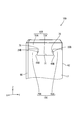
- Front view of terminal in embodiment 2 AA sectional view in FIG.
- FIG. 12 is a view corresponding to FIG. 12 in a state where the insulating member is separated from the main body.
- FIG. 15 is a view corresponding to FIG. 15, showing a state in which the insulating member is separated from the main body.
- FIG. 17 is a view corresponding to FIG. 17 with the insulating member separated from the main body.
- FIG. 19 corresponds to FIG. 19 and shows a state in which the insulating member is separated from the main body.
- FIG. 21 is a view corresponding to FIG. 21 with the insulating member separated from the main body.
- FIG. 23 is a view corresponding to FIG. 23 in a state where the insulating member is separated from the main body.
- FIG. 25 corresponds to FIG. 25 and shows a state in which the insulating member is separated from the main body.
- the direction toward the upper side in FIG. 6 (the Z direction in FIG. 6) is the front direction which is the fitting direction of the plate terminal 10, the direction toward the lower side in FIG. 6 is the rear direction, and the direction toward the right side in FIG.
- the direction (Y direction in FIG. 6) is defined as one of the width directions of the plate terminal 10, and the direction toward the left side in FIG.
- the direction toward the right side of FIG. 3 (the X direction in FIG. 3) is defined as one of the thickness directions of the plate terminals 10, and the direction toward the left side of FIG.
- the plate terminal 10 is attached to a resin housing (not shown), and as shown in FIGS. 1 and 2, a metal body 12 having a long plate shape in the front-rear direction, and a body
- the main body 12 includes a plate-shaped mounting portion 16 protruding forward from a front end surface 14 of the main body 12, and a separate insulating member 18 mounted on the mounting portion 16.
- the insulating member 18 is located on the front side of the front end face 14 of the main body 12. As described above, since the insulating member 18 is separate from the housing (not shown) to which the plate terminal 10 is attached, the insulating member 18 is compared with a conventional configuration in which the insulating member and the housing are integrally formed. Since it is not necessary to extend the insulating member 18 to the resin portion of the housing via the main body 12, the width of the main body 12 can be reduced.
- the front end face 14 of the main body 12 includes a first front end face 14A and a second front end face 14B, as shown in FIG.
- the length L1 in the width direction of the mounting portion 16 is set smaller than the length L2 in the width direction of the main body portion 12, and the first front end face 14 ⁇ / b> A sandwiches the mounting portion 16.
- One side in the width direction is set, and the second front end surface 14B is set to the other side in the width direction across the mounting portion 16.
- the first side surface 20, which is one side surface in the width direction of the mounting portion 16, is provided with a groove-shaped first concave portion 22.
- the second side surface 24, which is the other side surface, is provided with a groove-shaped second concave portion 26.
- a first inclined surface 30 that is inclined toward the front end surface 28 of the attachment portion 16 is provided at the front end of the plate surface of the attachment portion 16.
- a second inclined surface 32 that is inclined toward the first side surface 20 of the mounting portion 16 is provided at one side end of the mounting portion 16 in the width direction of the plate surface.
- a third inclined surface 34 that is inclined toward the second side surface 24 of the mounting portion 16 is provided at the other end of the mounting portion 16 in the width direction of the plate surface.
- the insulating member 18 is formed of resin, and as shown in FIG. 5, a first insulating member 36 that is attached to the mounting portion 16 from the first side surface 20 side of the mounting portion 16, and a second side surface 24 of the mounting portion 16. And a second insulating member 38 attached to the attaching portion 16 from the side. As shown in FIG. 2, the first insulating member 36 and the second insulating member 38 have a contact surface 40A and a contact surface 40B that are in contact with each other.
- the first insulating member 36 has a shape that is long in the front-rear direction, and the other side surface of the first insulating member 36 in the width direction (the first side surface 20 of the mounting portion 16).
- a first convex portion 42 and a second groove portion 44 are provided on the opposite side surface).
- the first convex portion 42 is provided at a position corresponding to the first concave portion 22 of the mounting portion 16 as shown in FIG. 6, and the first convex portion 42 of the first insulating member 36 as shown in FIG. Are fitted in the first recesses 22 of the mounting portion 16.
- the first protrusion 42 contacts the inner surface of the first recess 22, so that the displacement of the first insulating member 36 in the front-rear direction is restricted.
- the second groove portion 44 is provided at a position corresponding to the second inclined surface 32 and the first side surface 20 of the mounting portion 16 as shown in FIG. 6, and as shown in FIG.
- the second inclined surface 32 and the first side surface 20 of the mounting portion 16 are covered in the front-rear direction of the mounting portion 16.
- the inner surface of the second groove portion 44 is provided so as to face the second inclined surface 32 and the first side surface 20 of the mounting portion 16 and is in contact with the mounting portion 16 in the front-rear direction. Thereby, the displacement of the first insulating member 36 in the thickness direction is suppressed.
- the inner surface of the second groove portion is in contact with the second inclined surface 32 of the mounting portion 16 in the front-rear direction, the inner surface of the second groove portion is part of the second inclined surface of the mounting portion.
- the contact area between the second groove portion 44 and the mounting portion 16 is larger than in the configuration in which the first insulating member 36 is in contact with the contact portion, and the displacement of the first insulating member 36 in the thickness direction can be suppressed.
- the second groove portion 44 may be configured to cover a part of the second inclined surface 32 and a part of the first side surface 20 of the attachment portion 16 as long as the touch finger to the attachment portion 16 can be suppressed.
- a configuration that covers a part of the second inclined surface 32 and the first side surface 20 in the front-rear direction or a configuration that covers a part of the second inclined surface 32 and the first side surface 20 in a direction intersecting the front-rear direction is provided. Is also good.
- the inner surface of the second groove portion 44 may be configured to contact a part of the second inclined surface 32 of the mounting portion 16.
- the contact surface 40A of the first insulating member 36 is provided on the other side surface in the width direction, and the contact surface 40A is provided with an opening 46 opened. ing.
- the second insulating member 38 has a first covering portion 48 having a long shape in the front-rear direction and a long shape in the width direction, and one side of the first covering portion 48 in the width direction. And a second covering portion 50 protruding from the side surface of the second member in the width direction.
- a second convex portion 52 and a third groove portion 54 are provided on one side surface in the width direction of the first cover portion 48 (the side surface facing the second side surface 24 of the mounting portion 16). Is provided.
- the second convex portion 52 of the first cover portion 48 is provided at a position corresponding to the second concave portion 26 of the mounting portion 16, and as shown in FIG.
- the second convex portion 52 is fitted with the second concave portion 26 of the mounting portion 16.
- the third groove portion 54 of the first cover portion 48 is provided at a position corresponding to the third inclined surface 34 and the second side surface 24 of the mounting portion 16, and as shown in FIG.
- the third groove portion 54 covers the third inclined surface 34 and the second side surface 24 of the mounting portion 16 in the front-rear direction of the mounting portion 16.
- the inner surface of the third groove portion 54 is provided to face the third inclined surface 34 and the second side surface 24 of the mounting portion 16 and is in contact with the mounting portion 16 in the front-rear direction. Thereby, the displacement of the second insulating member 38 in the thickness direction is suppressed.
- the inner surface of the third groove portion 54 is in contact with the third inclined surface 34 of the mounting portion 16 in the front-rear direction, the inner surface of the third groove portion is part of the third inclined surface of the mounting portion.
- the contact area between the third groove portion 54 and the mounting portion 16 is increased as compared with the configuration in which the first insulating member 36 contacts the first insulating member 36, and the displacement of the first insulating member 36 in the thickness direction can be suppressed.
- the third groove 54 may be configured to cover a part of the third inclined surface 34 and the second side surface 24 of the mounting portion 16 as long as the touch finger to the mounting portion 16 can be suppressed.
- the inner surface of the third groove 54 may be configured to contact a part of the third inclined surface 34 of the mounting portion 16.
- a first groove 56 that is long in the width direction is provided on the rear surface of the second cover 50.
- the first groove portion 56 is provided at a position corresponding to the first inclined surface 30 of the mounting portion 16 and the front end surface 28 of the mounting portion 16.
- the first inclined surface 30 and the front end surface 28 are covered over the width direction of the mounting portion 16.
- the inner surface of the first groove portion 56 is provided to face the first inclined surface 30 of the mounting portion 16 and the front end surface 28 of the mounting portion 16, and is in contact with the surface across the width direction of the mounting portion 16. I have. Thereby, the displacement of the second insulating member 38 in the thickness direction is suppressed.
- the inner surface of the first groove portion 56 is in contact with the first inclined surface 30 of the mounting portion 16 across the width direction, the inner surface of the first groove portion is a part of the first inclined surface of the mounting portion.
- the contact area between the first groove portion 56 and the mounting portion 16 is larger than in the configuration in which the first insulating member 36 contacts the first insulating member 36, and the displacement of the first insulating member 36 in the thickness direction can be suppressed.
- the first groove portion 56 may be configured to cover a part of the first inclined surface 30 and the front end surface 28 of the attachment portion 16 as long as the touch finger to the attachment portion 16 can be suppressed.
- a configuration that covers a part of the first inclined surface 30 and the front end surface 28 in the front-rear direction or a configuration that covers a part of the first inclined surface 30 and the front end surface 28 that intersects the front-rear direction may be used.
- the inner surface of the first groove portion 56 may be configured to contact a part of the first inclined surface 30 of the mounting portion 16.
- the contact surface 40 ⁇ / b> B of the second insulating member 38 is provided on one side surface in the width direction of the second cover 50, and the contact surface 40 ⁇ / b> B has the first surface.
- a protrusion 58 is provided to protrude.
- the first protrusion 58 of the second insulating member 38 is press-fitted into the opening 46 of the first insulating member 36, and the first insulating member 36 and the second insulating member 38 are joined.
- the insulating member 18 is attached by attaching the separate insulating member 18 to the mounting portion 16, a configuration in which the insulating member is formed in the mounting portion by insert molding as in the related art (the plate terminal is attached to the mold). 10 metal parts are set, the resin is poured into a mold, and the resin is cooled and solidified), thereby assembling faster. Further, since a dedicated mold is not required, it is possible to contribute to cost reduction.
- a side surface 60 on one side in the width direction of the first insulating member 36 and a side surface 62 on one side in the width direction of the main body 12 are flush with each other.
- the side surface 64 on the other side in the width direction is flush with the side surface 66 on the other side in the width direction of the main body 12.
- the first insulating member 36 covers the entire first front end face 14A of the main body 12 from the front.
- the first covering portion 48 of the second insulating member 38 covers the entire second front end face 14B of the main body 12 from the front.
- the second covering portion 50 of the second insulating member 38 covers the front end face 28 of the mounting portion 16 from the front.
- the insulating member 18 covers the front end surface 28 of the mounting portion 16 and a part of the front end surface 14 of the main body portion 12, the insulating member 18 is provided from the front of the plate terminal (terminal) 10. Touching the metal part (the mounting part 16 and the main body part 12) of the plate terminal (terminal) 10 is suppressed. Further, since the insulating member 18 is separate from the housing to which the plate terminal (terminal) 10 is attached, the insulating member 18 is compared with a conventional configuration in which the insulating member and the housing are integrally formed. Does not need to extend to the resin portion of the housing via the main body 12, so that the width of the plate terminal (terminal) 10 can be reduced.
- the first insulating member 36 is attached to the attaching portion 16 from the first side surface (one side surface) 20 of the attaching portion 16, and then the second insulating member 38 is attached to the second side surface (the other side) of the attaching portion 16.
- the insulating member 18 can be mounted to the mounting portion 16. Therefore, as in the prior art, a configuration in which the insulating member is formed in the mounting portion by insert molding (the metal portion of the plate terminal (terminal) 10 is set in the mold, the resin is poured into the mold, and the resin is cooled and solidified. ), And can be assembled faster. Further, since a dedicated mold is not required, it is possible to contribute to cost reduction.
- the width of the entire plate terminal (terminal) 10 can be reduced. Can be.
- first convex portion 42 of the first insulating member 36 is fitted into the first concave portion 22 of the mounting portion 16, and the second convex portion 52 of the second insulating member 38 is fitted into the second concave portion 26 of the mounting portion 16.
- first convex portion 42 of the first insulating member 36 hits the inner surface of the first concave portion 22 of the mounting portion 16, and the second convex portion of the second insulating member 38. Since the convex portion 52 hits the inner surface of the second concave portion 26 of the mounting portion 16, the displacement of the insulating member 18 in the front-rear direction is restricted.
- first insulating member 36 and the second insulating member 38 can be joined by press-fitting the first projecting portion 58 of the second insulating member 38 into the opening 46 of the first insulating member 36.
- the insulating member 18 has the thickness of the plate terminal (terminal) 10. The displacement in the direction can be suppressed.
- the 1st slope 30 of the attachment part 16 of the main-body part 12 is provided over the width direction of the attachment part 16 as shown in FIG. 5, for example.
- the first groove portion 56 is also provided across the width direction of the mounting portion 16. The above configuration is preferable from the viewpoint that a larger contact area between the first groove 56 and the first inclined surface 30 can be ensured.
- “provided over the width direction of the mounting portion 16” means that, for example, in the case of the first inclined surface 30, the first inclined surface 30 is formed from one end side to the other end side in the width direction of the mounting portion 16. means.
- the inner surface of the second groove portion 44 of the first insulating member 36 is in contact with the first side surface (one side surface) 20 of the mounting portion 16 and the second inclined surface 32, and the second insulating member. Since the inner surface of the third groove portion 54 of the first covering portion 48 of the first 38 is in contact with the second side surface (the side surface on the other side) 24 and the third inclined surface 34, the insulating member 18 is Displacement in the thickness direction of the terminal (terminal) 10 can be suppressed. In addition, it is preferable that the 2nd slope 32 and the 3rd slope 34 are provided over the front-back direction of the attachment part 16, as shown in FIG. 5, for example.
- the second groove portion 44 and the third groove portion 54 are preferably provided in the front-rear direction of the mounting portion 16.
- the above configuration is preferable from the viewpoint that a larger contact area between the second groove 44 and the second inclined surface 32 and a larger contact area between the third groove 54 and the third inclined surface 34 can be secured.
- the plate terminal 10A of the present embodiment will be described with reference to FIGS.
- the plate terminal 10A is different from the plate terminal 10 of the first embodiment, and the insulating member 18A is formed by one member.
- the plate terminal 10 ⁇ / b> A is a metal body 12 having a long plate shape in the front-rear direction, and a plate that is connected to the body 12 and protrudes forward from a front end surface 14 of the body 12. It comprises a mounting portion 16A in the shape of a letter, and a separate insulating member 18A mounted on the mounting portion 16A from the front.
- a first inclined surface 30 that is inclined toward the front end surface 28 of the mounting portion 16A is provided.
- the insulating member 18A includes a first insulating member 36A and a second insulating member 38A provided integrally with the first insulating member 36A.
- the first insulating member 36A has a long shape in the front-rear direction, is attached to the one side surface 20 of the mounting portion 16A, and has a second side surface in the width direction of the first insulating member 36A (the second side surface of the mounting portion 16A).
- a first convex portion 42 is provided on the side surface facing the first side surface 20).
- the first convex portion 42 is provided at a position corresponding to the first concave portion 22 of the mounting portion 16A.
- the first convex portion 42 becomes the first of the mounting portion 16A.
- the recess 22 is fitted.
- the first protrusion 42 is in contact with the inner surface of the first concave portion 22, so that the displacement of the first insulating member 36A in the front-rear direction is restricted.
- the second insulating member 38A has a long shape in the width direction, and has a second covering portion 50 connected to an upper end portion of the first insulating member 36A, and a first covering portion 50 of the second covering portion 50.
- a first cover 48 projecting rearward from an end opposite to the end connected to the insulating member 36A.
- a second convex portion 52 is provided on one side surface of the first cover portion 48 in the width direction (a side surface facing the second side surface 24 of the mounting portion 16A).
- the second convex portion 52 is provided at a position corresponding to the second concave portion 26 of the mounting portion 16A.
- the first protrusion 42 When the first protrusion 42 is fitted in the first recess 22 and the second protrusion 52 is fitted in the second recess 26, when the insulating member 18A is displaced in the front-rear direction, the first protrusion 42 is Since the second protrusion 52 abuts against the inner surface of the second recess 26 and the inner surface of the second recess 26, the displacement of the insulating member 18A in the front-rear direction is restricted.
- a first groove portion 56 that is long in the width direction is provided on the rear surface of the second cover portion 50.
- the first groove portion 56 is provided at a position corresponding to the first inclined surface 30 of the attachment portion 16A and the front end surface 28 of the attachment portion 16A, and the inner surface of the first groove portion 56 is provided with the first inclined surface 30 of the attachment portion 16A. And is in surface contact with the front end surface 28 of the mounting portion 16A. This suppresses displacement of the insulating member 18A in the thickness direction.
- the first insulating member 36A and the first cover part 48 are elastically displaceable in the width direction. Thereby, when attaching the insulating member 18A to the attaching portion 16A from the front, the front end of the attaching portion 16A hits the rear end of the first insulating member 36A and the rear end of the first cover portion 48, and the first insulating member 36A and the first The cover portions 48 are elastically displaced in directions away from each other. In this state, the insulating member 18A is displaced backward until the first convex portion 42 is fitted into the first concave portion 42 and the second convex portion 52 is fitted into the second concave portion 26. It can be attached to the attachment portion 16A.
- the insulating member 18A can be attached to the attaching portion 16A by the assembling, it is possible to attach the insulating member 18A more easily than in the case where the insulating member 18A is attached to the attaching portion 16A by insert molding.
- Other configurations are the same as those of the plate terminal 10 of the first embodiment.
- the first fitting portion (first convex portion) 42 of the first insulating member 36A fits with the first concave portion (third fitting portion) 22 of the mounting portion 16A.
- the second convex portion (second fitting portion) 52 of the first covering portion 48 of the second insulating member 38A is fitted to the second concave portion (fourth fitting portion) 26 of the mounting portion 16A, thereby providing insulation.
- the member 18A is restricted from being displaced in the front-rear direction from the main body 12, and the insulating member 18A is prevented from coming off the main body 12.
- first convex portion 42 of the first insulating member 36A is fitted into the first concave portion 22 of the mounting portion 16A
- second convex portion 52 of the first covering portion 48 of the second insulating member 38A is formed by the second convex portion 52 of the mounting portion 16A.
- the first covering portion 48 of the first insulating member 36A and the second insulating member 38A is elastically displaceable in the width direction, the first fitting portion (first convex portion) 42 of the insulating member 18A and the first covering portion 48 are formed.
- the second convex portion (second fitting portion) 52 is fitted into the first concave portion (third fitting portion) 22 and the second concave portion (fourth fitting portion) 26 of the mounting portion 16A, the first insulation
- the first fitting portion (first convex portion) 42 and the second convex portion (second fitting portion) of the insulating member 18A are provided.
- the insulating member 18A can be attached to the attaching portion 16A by assembling, so that the attaching can be easily performed as compared with the case where the insulating member is attached to the attaching portion by insert molding.
- the insulating member 18A has a thickness equal to the thickness of the plate terminal (terminal) 10A. The displacement in the direction can be suppressed.
- the plate terminal 10B of the present embodiment will be described with reference to FIGS.
- the insulating member 18B of the plate terminal 10B is formed of one member as in the case of the plate terminal 10A of the second embodiment. However, unlike the plate terminal 10A of the second embodiment, the insulating member 18B is attached to the mounting portion 16A by insert molding.
- the first insulating member 36B of the insulating member 18B and the first covering portion 48A of the second insulating member 38B are configured to be unable to elastically displace in the width direction.
- the insulating member 18B is less likely to come off the mounting portion 16A than the second plate terminal 10A.
- Other configurations are the same as those of the plate terminal 10A of the second embodiment, and therefore, the same reference numerals as those of the second embodiment are given and the description is omitted.
- the plate terminal 10C of the present embodiment will be described with reference to FIGS.
- the insulating member 18C of the plate terminal 10C of the present embodiment is attached to the mounting portion 16B by insert molding similarly to the plate terminal 10B of the third embodiment, but the shape of the insulating member 18C and the shape of the mounting portion 16B are different. It is different from the shapes of the insulating member 18B and the mounting portion 16A in the third embodiment.
- the mounting portion 16 ⁇ / b> B extends from the first mounting portion 68 protruding forward from one end in the width direction of the front end surface 14 of the main body 12, and from the other end in the width direction of the front end surface 14 of the main body 12. And a second mounting portion 70 protruding forward.
- the first mounting portion 68 and the second mounting portion 70 are arranged at a predetermined interval in the width direction.
- the insulating member 18C has a long shape in the width direction and is provided from the first mounting portion 68 to the second mounting portion 70, and the front end surfaces 28 of the first mounting portion 68 and the second mounting portion 70, and the main body portion.
- a second covering portion 50A that covers the front end surface 14 of the second 12; and a second projecting portion 72 that projects from the rear surface of the second covering portion 50 toward between the first mounting portion 68 and the second mounting portion 70. It is configured.
- first convex portion (first fitting portion) 42A protrudes from one side surface 60A, and a second convex portion (first fitting portion) 42A from the other side surface 64A.
- a second fitting part) 52A is protruded.
- a first concave portion (third fitting portion) 22A that fits with the first convex portion 42A is provided on a first side surface 20A of the first mounting portion 68 that faces the side surface 60A on one side of the second projecting portion 72.
- the second mounting portion 70 has a surface 24A facing the other side surface 64A of the second projecting portion 72, and a second concave portion (fourth engaging portion) 52A fitted with the second convex portion (second fitting portion) 52A. (Fitting portion) 26A is provided.
- the insulating member 18C is displaced in the front-rear direction with respect to the mounting portion 16B. Is restricted, and the detachment of the insulating member 18C from the mounting portion 16B is suppressed.
- Other configurations are the same as those of the plate terminal 10 ⁇ / b> B of the third embodiment.
- the first convex portion (first fitting portion) 42A of the insulating member 18C is fitted to the first concave portion (third fitting portion) 22A of the mounting portion 16B, and the insulating member 18C is insulated.
- the second convex portion (second fitting portion) 52A of the member 18C With the second concave portion (fourth fitting portion) 26A of the mounting portion 16B, the insulating member 18C is moved from the mounting portion 16B in the front-rear direction. Is prevented from coming off from the mounting portion 16B.
- the plate terminal 10D of the present embodiment will be described with reference to FIGS.
- the plate terminal 10D differs from the plate terminal 10C of the fourth embodiment in that the insulating member 18D is attached to the attachment portion 16C by press fitting.
- the mounting portion 16 ⁇ / b> C is formed from a first mounting portion 68 ⁇ / b> A protruding forward from one widthwise end of the front end face 14 of the main body 12 and the other end in the widthwise direction of the front end face 14 of the main body 12. And a second mounting portion 70A protruding forward.
- the first mounting portion 68A and the second mounting portion 70A are arranged at predetermined intervals in the width direction.
- a pair of protrusions 76 are provided on the first side surface 20B and the second side surface 24B of the first mounting portion 68A and the second mounting portion 70A, which face each other.
- the insulating member 18D has a long shape in the width direction, is provided from the first mounting portion 68A to the second mounting portion 70A, and has a front end surface 28 of the first mounting portion 68A and the second mounting portion 70A, and a main body portion.
- a second covering portion 50A that covers the front end surface 14 of the second mounting portion 12, and a second projecting portion 72A that projects from the rear surface of the second covering portion 50A toward between the first mounting portion 68A and the second mounting portion 70A. It is configured.
- the length between the tips of the pair of protrusions 76 is shorter than the length in the width direction of the second protrusion 72A of the insulating member 18D, and the insulating member 18D is attached to the attachment 16C by press fitting.
- Other configurations are the same as those of the plate terminal 10 ⁇ / b> C of the fourth embodiment.
- the plate terminal 10E of the present embodiment will be described with reference to FIGS.
- the plate terminal 10E is different from the plate terminal 10B of the third embodiment in that the insulating member 18E is mounted to the mounting portion 16D by press fitting.
- the mounting portion 16D is provided so as to protrude forward from the front end surface 14 of the main body portion 12, and the first side surface 20 on one side and the second side surface 24 on the other side of the mounting portion 16D have a pair of protrusions. 76A protrudes.
- the insulating member 18E includes a first insulating member 36C, and a second insulating member 38C provided integrally with the first insulating member 36C.
- the first insulating member 36C has a long shape in the front-rear direction, and is attached to the first side surface 20 on one side of the attaching portion 16D.
- the second insulating member 38C has a shape elongated in the width direction, and is opposite to the second covering portion 50B connected to the upper end portion of the first insulating member 36C and the end portion of the second covering portion 50B connected to the first insulating member 36C.
- a first cover portion 48B protruding rearward from the end of the first cover portion 48B.
- the length between the tips of the pair of protrusions 76A is longer than the length between the first insulating member 36C of the insulating member 18E and the first covering portion 48B of the second insulating member 38C, and the insulating member 18E Is mounted on the mounting portion 16D by press fitting.
- Other configurations are the same as those of the plate terminal 10 ⁇ / b> B of the third embodiment.
- the plate terminal 10F of the present embodiment will be described with reference to FIGS.
- the plate terminal 10F has a configuration in which the insulating member 18F is attached to the mounting portion 16E by press-fitting, similarly to the plate terminal 10E of Embodiment 6, but the insulating member 18F is provided with a third convex portion 80,
- the mounting portion 18F is different from the plate terminal 10E of the sixth embodiment in that a fourth concave portion 82 fitted with the third convex portion 80 is provided.
- the third convex portion 80 is provided between the first insulating member 36C of the insulating member 18F and the first covering portion 48B of the second insulating member 38C, and is provided so as to project rearward from the rear surface of the second covering portion 50B. ing.
- the fourth concave portion 82 is provided to open at a position corresponding to the third convex portion 80 at the front end of the mounting portion 16E.
- the technology disclosed in this specification is not limited to the embodiments described above and illustrated in the drawings, and includes, for example, the following various aspects.
- the first protruding portion 58 of the second covering portion 50 of the second insulating member 38 is press-fitted into the opening 46 of the first insulating member 36 so that the first insulating member 36 and the second Although the insulating member 38 is joined, for example, the first insulating member and the second insulating member may be joined by welding, or may be joined by ultrasonic joining.
- the first convex portion 42 provided on the first insulating member 36 is fitted into the first concave portion 22 provided on the mounting portion 16, so that the first insulating member 36 can be moved in the front-rear direction.
- the first insulating member may be provided with a concave portion
- the mounting portion may be provided with a convex portion
- the concave portion of the first insulating member may be fitted with the convex portion of the mounting portion.
- the second convex portion 52 provided on the second insulating member 38 is fitted into the second concave portion 26 provided on the mounting portion 16, so that the front-back direction of the second insulating member 38.
- a configuration may be adopted in which a concave portion is provided in the second insulating member, a convex portion is provided in the mounting portion, and the concave portion of the second insulating member is fitted to the convex portion of the mounting portion.
- the first insulating member 36 is mounted from the first side surface 20 side of the mounting portion 16
- the second insulating member 38 is mounted from the second side surface 24 side of the mounting portion 16.
- the insulating member may be attached to the attachment portion by press fitting.
- the first insulating member 36 and the second insulating member 38 are configured to entirely cover the first front end face 14A and the second front end face 14B of the main body 12, but a part thereof is used.
- the length L2 in the width direction of the main body portion and the sum L3 of the lengths in the width direction of the first insulating member 36 and the second insulating member 38 are set to be the same length. May be L2 or less.
- the insulating member 18 includes the first insulating portion 36 and the second insulating member 38 has been described, but the present invention is not limited thereto.
- the first insulating member and the second insulating member can be integrated.
- 10A, 10B, 10C, 10D, 10E, 10F Plate terminal (terminal) 12: body part 14: front end face 14A: first front end face 14B: second front end face 16, 16A, 16B, 16C, 16D, 16E: mounting part 18, 18A, 18B, 18C, 18D, 18E, 18F: insulating member 20, 20A, 20B: 1st side surface (one side surface) 22, 22A: first concave portion (third fitting portion) 24, 24A, 24B: second side surface (the other side surface) 26, 26A: second concave portion (fourth fitting portion) 28: front end surface 30: first inclined surface 32: second inclined surface 34: third inclined surface 36, 36A, 36B, 36C: first insulating member 38, 38A, 38B, 38C: second insulating member 40A: contact surface 40B: contact surface 42, 42A: first convex portion (first fitting portion) 44: 2nd groove part 46: Opening part 48, 48A, 48B: 1st covering part 50, 50A
- first groove portion 56 first groove portion 58: first projecting portion 60, 60A, 60B: one side surface 62: one side surface 64, 64A, 64B: the other side surface 66: the other side surface 72, 72A: second protrusion
Abstract
本明細書によって開示される板端子(端子)10は、前後方向に長い金属製の板状をなす本体部12と、本体部12と連なり、別体の絶縁部材18が取付けられる取付部16であって、本体部12の前端面14から前方に突出する板状の取付部16と、を備え、絶縁部材18は、本体部12の前端面14より前方に位置しており、取付部16の前端面28、及び本体部12の前端面14の少なくとも一部を覆っている。
Description
本明細書によって開示される技術は、端子に関する。
従来の端子の一例として、特表2016-522550号公報(下記特許文献1)に記載のピンコンタクト要素が知られている。ピンコンタクト要素は、扁平コンタクトの形状をなしており、コンタクト部材と、コンタクト部材と一体に形成されたコンタクト保護部材と、を備える。コンタクト保護部材は、コンタクト部材の上部及び両側縁を覆っており、コンタクト部材のコンタクト面は、外部に露出している。
ピンコンタクト要素は、コネクタ要素に備えられるものであり、コネクタ要素には、コンタクト保護部材と一体に成形されたハウジングが設けられている。ハウジングには、ピンコンタクト要素の周囲を囲むようにコンタクト保護カラーが設けられており、コンタクト保護カラーの上部は開口している。また、コンタクト保護カラーとピンコンタクト要素の間の隙間は、試験指が入らない程度の隙間となっており、試験指がコンタクト部材のコンタクト面に直接接触することは抑制される。
コンタクト保護部材は、ハウジングと一体に成形されているため、コンタクト部材の両側縁がコンタクト保護部材に覆われており、ピンコンタクト要素の幅が大きくなるという問題がある。
本明細書で開示される端子は、前後方向に長い金属製の板状をなす本体部と、前記本体部と連なり、別体の絶縁部材が取付けられる取付部と、を備え、前記取付部は板状をなし、前記本体部の前端面から前方に突出するものとされ、前記絶縁部材は、前記本体部の前端面より前方に位置しており、前記取付部の前端面、及び本体部の前端面の少なくとも一部を覆っている。
絶縁部材は、取付部の前端面、及び本体部の前端面の少なくとも一部を覆っているため、端子の前方から端子の金属部位(取付部及び本体部)へ触指することが抑制される。また、絶縁部材は、端子が取付けられるハウジングとは別体であるため、従来のように、絶縁部材とハウジングとが一体に成形される構成と比較して、絶縁部材を、本体部を介してハウジングの樹脂部まで延在させる必要がないことから、端子の幅を抑えることができる。
また、前記取付部は、前記取付部の前端部に前記取付部の前端面に向けて板厚が薄くなる第1傾斜面を有し、前記絶縁部材は、前記絶縁部材の後方に前記第1傾斜面の少なくとも一部を覆う第1溝部を有する構成としても良い。
絶縁部材の第1溝部が、取付部の第1傾斜面の少なくとも一部を覆うことで、絶縁部材が端子の厚さ方向に変位した際に、第1溝部の内面が第1傾斜面に当たるため、絶縁部材が端子の厚さ方向に変位することを抑制することができる。
また、前記第1溝部は、前記第1傾斜面を前記取付部の幅方向に亘って覆う構成としても良い。
第1溝部が第1傾斜面を取付部の幅方向に亘って覆うことで、第1溝部が第1傾斜面を幅方向について一部を覆う構成と比較して、絶縁部材が端子の厚さ方向に変位することをさらに抑制することができる。
また、前記取付部の板面の幅方向の両側端部のうち、一方側の側端部には、前記取付部の前記一方側の側面に向けて板厚が薄くなる第2傾斜面を有し、他方側の側端部には、前記取付部の前記他方側の側面に向けて板厚が薄くなる第3傾斜面を有し、前記絶縁部材は、前記絶縁部材に前記第2傾斜面の少なくとも一部を覆う第2溝部と、前記絶縁部材に前記第3傾斜面の少なくとも一部を覆う第3溝部と、を有する構成としても良い。
絶縁部材の第2溝部が、取付部の第2傾斜面の少なくとも一部を覆い、絶縁部材の第3溝部が取付部の第3傾斜面の少なくとも一部を覆うことで、絶縁部材が端子の厚さ方向に変位した際に、第2溝部の内面が第2傾斜面に当たり、第3溝部の内面が第3傾斜面に当たるため、絶縁部材が端子の厚さ方向に変位することを抑制することができる。
また、前記第2溝部は、前記第2傾斜面を前記取付部の前後方向に亘って覆い、前記第3溝部は、前記第3傾斜面を前記取付部の前後方向に亘って覆う構成としても良い。
第2溝部が第2傾斜面を前後方向に亘って覆い、第3溝部が第3傾斜面を前後方向に亘って覆うことで、第2溝部が第2傾斜面を前後方向について一部を覆い、第3溝部が第3傾斜面を前後方向について一部を覆う構成と比較して、絶縁部材が端子の厚さ方向に変位することをさらに抑制することができる。
また、前記取付部の幅方向の長さは、前記本体部の幅方向の長さよりも小さく設定されており、前記本体部の前端面は、前記取付部を挟んで、幅方向の一方側に位置する第1前端面と、幅方向の他方側に位置する第2前端面と、から構成されており、前記絶縁部材は、前記取付部の幅方向の両側面のうち、前記一方側の側面から、前記取付部に取付けられる第1絶縁部材と、前記他方側の側面から、前記取付部に取付けられる第2絶縁部材と、から構成され、前記第1絶縁部材及び前記第2絶縁部材は、互いに接合されており、前記第1絶縁部材は、前後方向に長い形状をなし、前記本体部の前記第1前端面の前方に位置し、前記本体部の前記第1前端面の少なくとも一部を覆っており、前記第2絶縁部材は、前後方向に長い形状をなし、前記本体部の前記第2前端面の前方に位置し、前記本体部の前記第2前端面の少なくとも一部を覆う第1覆い部と、幅方向に長い形状をなし、前記取付部の前端面の前方に位置し、前記取付部の前端面を覆う第2覆い部と、を有している構成としても良い。
例えば、第1絶縁部材を取付部の一方側の側面から取付部に取付け、次に、第2絶縁部材を取付部の他方側の側面から取付部に取付け、さらに、第1絶縁部材と第2絶縁部材とを接合することで、絶縁部材を取付部に組付けることができる。このため、従来のように、インサート成形により絶縁部材を取付部に形成する構成(金型に端子の金属部をセットし、金型に樹脂を流し込み、樹脂を冷却して固化させる構成)と比較して、早く組立てることができる。また、専用の金型が不要となるため、コストの低減に寄与することができる。
また、前記取付部に取付けられた前記第1絶縁部材及び前記第2絶縁部材の幅方向の長さの和が、前記本体部の幅方向の長さ以下である構成としても良い。
第1絶縁部材及び第2絶縁部材の幅方向の長さの和が、本体部の幅方向の長さ以下であるため、端子全体の幅を抑えることができる。
また、前記取付部の前記一方側の側面には、第1凹部が開口して設けられ、前記第1絶縁部材の、前記取付部の前記一方側の側面と対向する面には、前記第1凹部と嵌合する第1凸部が突設され、第1凹部と第1凸部とが嵌合することで、前記第1絶縁部材は、前後方向への変位が規制されており、前記取付部の前記他方側の側面には、第2凹部が開口して設けられ、前記第2絶縁部材の前記第1覆い部の、前記取付部の前記他方側の側面と対向する面には、前記第2凹部と嵌合する第2凸部が突設され、第2凹部と第2凸部とが嵌合することで、前記第2絶縁部材は、前後方向への変位が規制される構成としても良い。
第1絶縁部材の第1凸部を取付部の第1凹部に嵌合し、第2絶縁部材の第2凸部を、取付部の第2凹部に嵌合することで、絶縁部材が前後方向に変位しようとすると、第1絶縁部材の第1凸部が、取付部の第1凹部の内面に当たり、第2絶縁部材の第2凸部が取付部の第2凹部の内面に当たるため、絶縁部材が前後方向に変位することが規制される。
また、前記第1絶縁部材、及び、前記第2絶縁部材の前記第2覆い部は、互いに接触する接触面をそれぞれ有しており、前記第1絶縁部材側の前記接触面には、開口部が設けられており、前記第2絶縁部材の前記第2覆い部側の前記接触面には、第1突出部が突設されており、前記第1突出部が前記開口部に圧入されることで、前記第1絶縁部材と前記第2覆い部とは互いに接合される構成としても良い。
第1絶縁部材の第1突出部を第2絶縁部材の開口部に圧入することで、第1絶縁部材と第2絶縁部材とを接合することができる。
また、前記取付部の板面の前端部には、前記取付部の前端面に向けて板厚が薄くなる第1傾斜面が設けられており、前記第2絶縁部材の前記第2覆い部の後面には、幅方向に長い第1溝部が開口して設けられており、前記第1溝部の内面は、前記取付部の前端面及び前記第1傾斜面に面で接触している構成としても良い。
第1溝部の内面は、本体部の取付部の前端面及び第1傾斜面に面で接触しているため、絶縁部材が、端子の厚さ方向に変位することを抑制することができる。
また、前記取付部の板面の幅方向の両側端部のうち、前記一方側の側端部には、前記取付部の前記一方側の側面に向けて板厚が薄くなる第2傾斜面が設けられており、前記第1絶縁部材の、前記取付部の前記一方側の側面と対向する面には、前後方向に長い第2溝部が開口して設けられ、前記第2溝部の内面は、前記取付部の前記一方側の側面、及び、前記第2傾斜面と面で接触しており、前記取付部の板面の幅方向の両側端部のうち、前記他方側の側端部には、前記取付部の前記他方側の側面に向けて板厚が薄くなる第3傾斜面が設けられており、前記第2絶縁部材の前記第1覆い部の、前記取付部の前記一方側の側面と対向する面には、前後方向に長い第3溝部が開口して設けられ、前記第3溝部の内面は、前記取付部の前記他方側の側面、及び、前記第3傾斜面と面で接触している構成としても良い。
第1絶縁部材の第2溝部の内面は、取付部の一方側の側面、及び、第2傾斜面と面で接触しており、第2絶縁部材の第1覆い部の第3溝部の内面は、他方側の側面、及び、第3傾斜面と面で接触していることから、絶縁部材が、端子の厚さ方向に変位することを抑制することができる。
また、前記取付部の幅方向の長さは、前記本体部の幅方向の長さよりも小さく設定されており、前記本体部の前端面は、前記取付部を挟んで、幅方向の一方側に位置する第1前端面と、幅方向の他方側に位置する第2前端面と、から構成されており、前記絶縁部材は、前後方向に長い形状をなし、前記本体部の前記第1前端面の前方に位置し、前記本体部の前記第1前端面の少なくとも一部を覆う第1絶縁部材と、前記第1絶縁部材と一体をなす第2絶縁部材と、から構成されており、前記第2絶縁部材は前記第1絶縁部材と連なっており、前後方向に長い形状をなし、前記本体部の前記第2前端面の前方に位置し、前記本体部の前記第2前端面の少なくとも一部を覆う第1覆い部、及び、幅方向に長い形状をなし、前記取付部の前端面の前方に位置し、前記取付部の前端面を覆う第2覆い部を有しており、前記第1絶縁部材は、前記取付部の一方側の側面と対向する第1対向面を有し、前記第1対向面には、第1嵌合部が設けられ、前記第2絶縁部材の前記第1覆い部は、前記取付部の他方側の側面と対向する第2対向面を有し、前記第2対向面には、第2嵌合部が設けられ、前記取付部の前記一方側の側面には、前記第1嵌合部と嵌合する第3嵌合部が設けられ、前記取付部の前記他方側の側面には、前記第2嵌合部と嵌合する第4嵌合部が設けられており、前記第1嵌合部と前記第3嵌合部とが嵌合し、前記第2嵌合部と前記第4嵌合部とが嵌合することで、前記絶縁部材の前後方向への変位が規制される構成としても良い。
第1絶縁部材の第1嵌合部が、取付部の第3嵌合部と嵌合し、第2絶縁部材の第1覆い部の第2嵌合部が、取付部の第4嵌合部と嵌合することで、絶縁部材は、取付部から前後方向に変位することが規制され、絶縁部材が取付部から外れることが抑制される。
また、前記第1嵌合部は、前記第1対向面から前記取付部の前記一方側の側面に向けて突出する第1凸部とされ、前記第2嵌合部は、前記第2対向面から前記取付部の前記他方側の側面に向けて突出する第2凸部とされ、前記第3嵌合部は、前記取付部の前記一方側の側面に開口して設けられ、前記第1凸部と嵌合する第1凹部とされ、前記第4嵌合部は、前記取付部の前記他方側の側面に開口して設けられ、前記第2凸部と嵌合する第4凹部とされる構成としても良い。
第1絶縁部材の第1凸部が取付部の第1凹部と嵌合し、第2絶縁部材の第1覆い部の第2凸部が取付部の第2凹部と嵌合することで、絶縁部材は、取付部から前後方向に変位することが規制され、絶縁部材が取付部から外れることが抑制される。
また、前記第1絶縁部材及び前記第2絶縁部材の前記第1覆い部は、前記幅方向に弾性変位可能とされる構成としても良い。
第1絶縁部材及び第2絶縁部材の第1覆い部は幅方向に弾性変位可能となっているため、絶縁部材の第1嵌合部及び第2嵌合部を、取付部の第3嵌合部及び第4嵌合部に嵌合する際に、第1絶縁部材及び第2絶縁部材の第1覆い部を幅方向に弾性変位させることで、絶縁部材の第1嵌合部及び第2嵌合部を、取付部の第3嵌合部及び第4嵌合部の位置に変位させることができる。このように、組付けにより絶縁部材を取付部に取付けることが可能となるため、インサート成形により絶縁部材を取付部に取付ける場合と比較して、容易に取付けることができる。
また、前記取付部の板面の前端部には、前記取付部の前端面に向けて板厚が薄くなる第1傾斜面が設けられており、前記第2覆い部の後面には、幅方向に長い第1溝部が開口して設けられており、前記第1溝部の内面は、前記取付部の前端面及び前記第1傾斜面に面で接触している構成としても良い。
第1溝部の内面は、本体部の取付部の前端面及び第1傾斜面に面で接触しているため、絶縁部材が、端子の厚さ方向に変位することを抑制することができる。
第1溝部の内面は、本体部の取付部の前端面及び第1傾斜面に面で接触しているため、絶縁部材が、端子の厚さ方向に変位することを抑制することができる。
また、前記取付部は、前記本体部の前端面の一方側の端部から前方に突出する第1取付部と、前記本体部の前端面の他方側の端部から前方に突出する第2取付部と、を備え、前記絶縁部材は、前記第1取付部から前記第2取付部に亘って設けられ、前記第1取付部の前端面及び前記第2取付部の前端面、並びに前記本体部の前端面を覆う第2覆い部と、前記第2覆い部の後面から前記第1取付部と前記第2取付部との間に向けて突出する第2突出部と、を備え、前記第2突出部の幅方向の両側面のうち、一方の側面には第1嵌合部が設けられ、他方の側面には第2嵌合部が設けられており、前記第1取付部の前記第2突出部の一方の側面と対向する面には、前記第1嵌合部と嵌合する第3嵌合部が設けられ、前記第2取付部の前記第2突出部の他方の側面と対向する面には、前記第2嵌合部と嵌合する第4嵌合部が設けられており、前記第1嵌合部が前記第3嵌合部と嵌合し、前記第2嵌合部が前記第4嵌合部と嵌合することで、前記絶縁部材の前後方向への変位が規制される構成としても良い。
絶縁部材の第1嵌合部が、取付部の第3嵌合部と嵌合し、絶縁部材の第2嵌合部が、取付部の第4嵌合部と嵌合することで、絶縁部材は、取付部から前後方向に変位することが規制され、取付部から外れることが抑制される。
本明細書に開示される端子によれば、前端に絶縁部材を有する板状の端子の幅を抑えることができる。
<実施形態1>
図1から図11を参照して本実施形態の板端子(端子)10を説明する。以降の説明では、図6の上側に向かう方向(図6のZ方向)を板端子10の嵌合方向である前方向、図6の下側に向かう方向を後方向、図6の右側に向かう方向(図6のY方向)を板端子10の幅方向の一方、図6の左側に向かう方向を板端子10の幅方向の他方とする。また、図3の右側に向かう方向(図3のX方向)を板端子10の厚さ方向の一方、図3の左側に向かう方向を板端子10の厚さ方向の他方とする。
図1から図11を参照して本実施形態の板端子(端子)10を説明する。以降の説明では、図6の上側に向かう方向(図6のZ方向)を板端子10の嵌合方向である前方向、図6の下側に向かう方向を後方向、図6の右側に向かう方向(図6のY方向)を板端子10の幅方向の一方、図6の左側に向かう方向を板端子10の幅方向の他方とする。また、図3の右側に向かう方向(図3のX方向)を板端子10の厚さ方向の一方、図3の左側に向かう方向を板端子10の厚さ方向の他方とする。
板端子10は、樹脂製のハウジング(図示せず)に取付けられるものであって、図1、図2に示すように、前後方向に長い板状をなす金属製の本体部12と、本体部12と連なり、本体部12の前端面14から前方に突出する板状の取付部16と、取付部16に取付けられる別体の絶縁部材18と、から構成されている。絶縁部材18は、本体部12の前端面14よりも前側に位置している。このように、絶縁部材18は、板端子10が取付けられるハウジング(図示せず)とは別体であるため、従来のように、絶縁部材とハウジングとが一体に成形される構成と比較して、絶縁部材18を、本体部12を介してハウジングの樹脂部まで延在させる必要がないことから、本体部12の幅を抑えることができる。
本体部12の前端面14は、図5に示すように、第1前端面14Aと、第2前端面14Bとから構成されている。図6に示すように、取付部16の幅方向の長さL1は、本体部12の幅方向の長さL2よりも小さく設定されており、第1前端面14Aは、取付部16を挟んで幅方向の一方側とされ、第2前端面14Bは、取付部16を挟んで幅方向の他方側とされる。
図5、図6に示すように、取付部16の幅方向の一方側の側面である第1側面20には、溝状の第1凹部22が設けられており、取付部16の幅方向の他方側の側面である第2側面24には、溝状の第2凹部26が設けられている。
図5、図6、図7に示すように、取付部16の、板面の前端部には、取付部16の前端面28に向けて傾斜する第1傾斜面30が設けられている。
取付部16の、板面の幅方向の一方側の側端部には、取付部16の第1側面20に向けて傾斜する第2傾斜面32が設けられている。
取付部16の、板面の幅方向の他方側の側端部には、取付部16の第2側面24に向けて傾斜する第3傾斜面34が設けられている。
絶縁部材18は、樹脂により形成されており、図5に示すように、取付部16の第1側面20側から取付部16に取付けられる第1絶縁部材36と、取付部16の第2側面24側から取付部16に取付けられる第2絶縁部材38と、から構成されている。第1絶縁部材36及び第2絶縁部材38は、図2に示すように、互いに接触する接触面40A及び接触面40Bをそれぞれ有している。
第1絶縁部材36は、図8、図9に示すように、前後方向に長い形状をなしており、第1絶縁部材36の幅方向の他方側の側面(取付部16の第1側面20と対向する側面)には、第1凸部42、及び、第2溝部44が設けられている。
第1凸部42は、図6に示すように、取付部16の第1凹部22と対応する位置に設けられており、図2に示すように、第1絶縁部材36の第1凸部42は、取付部16の第1凹部22と嵌合している。これにより、第1絶縁部材36が前後方向に変位しようとすると、第1凸部42が第1凹部22の内面に当接するため、第1絶縁部材36の前後方向への変位が規制される。
第2溝部44は、図6に示すように、取付部16の第2傾斜面32及び第1側面20と対応する位置に設けられており、図2に示すように、第2溝部44は、取付部16の第2傾斜面32及び第1側面20を取付部16の前後方向に亘って覆っている。また、第2溝部44の内面は、取付部16の第2傾斜面32及び第1側面20と対向して設けられており、取付部16の前後方向に亘って面で接触している。これにより、第1絶縁部材36が厚さ方向に変位することが抑制される。また、第2溝部の内面は、取付部16の第2傾斜面32に前後方向に亘って面で接触していることから、第2溝部の内面が取付部の第2傾斜面の一部に接触する構成と比較して、第2溝部44と取付部16との接触面積が大きくなり、さらに第1絶縁部材36が厚さ方向に変位することを抑制できる。なお、第2溝部44は、取付部16への触指を抑制できる範囲であれば、取付部16の第2傾斜面32及び第1側面20の一部を覆う構成としても良い。例えば、第2傾斜面32及び第1側面20の前後方向の一部を覆う構成や第2傾斜面32及び第1側面20の前後方向に対して交差する方向の一部を覆う構成であっても良い。また、第2溝部44の内面が、取付部16の第2傾斜面32の一部に接触する構成としても良い。
図8、図9に示すように、第1絶縁部材36の接触面40Aは、幅方向の他方側の側面上に設けられており、接触面40Aには、開口部46が開口して設けられている。
第2絶縁部材38は、図10、図11に示すように、前後方向に長い形状をなす第1覆い部48と、幅方向に長い形状をなし、第1覆い部48の幅方向の一方側の側面から幅方向の一方に突出する第2覆い部50と、から構成されている。
図6に示すように、第1覆い部48の幅方向の一方側の側面(取付部16の第2側面24と対向する側面)には、第2凸部52、及び、第3溝部54が設けられている。
図6に示すように、第1覆い部48の第2凸部52は、取付部16の第2凹部26と対応する位置に設けられており、図2に示すように、第1覆い部48の第2凸部52は、取付部16の第2凹部26と嵌合している。これにより、第2絶縁部材38が前後方向に変位しようとすると、第2凸部52が第2凹部26の内面に当接するため、第2絶縁部材38の前後方向への変位が規制される。
図6に示すように、第1覆い部48の第3溝部54は、取付部16の第3傾斜面34及び第2側面24と対応する位置に設けられており、図2に示すように、第3溝部54は、取付部16の第3傾斜面34及び第2側面24を取付部16の前後方向に亘って覆っている。また、第3溝部54の内面は、取付部16の第3傾斜面34及び第2側面24と対向して設けられており、取付部16の前後方向に亘って面で接触している。これにより、第2絶縁部材38が厚さ方向に変位することが抑制される。また、第3溝部54の内面は、取付部16の第3傾斜面34に前後方向に亘って面で接触していることから、第3溝部の内面が取付部の第3傾斜面の一部に接触する構成と比較して、第3溝部54と取付部16との接触面積が大きくなり、さらに第1絶縁部材36が厚さ方向に変位することを抑制できる。なお、第3溝部54は、取付部16への触指を抑制できる範囲であれば、取付部16の第3傾斜面34及び第2側面24の一部を覆う構成としても良い。例えば、第3傾斜面34及び第2側面24の前後方向の一部を覆う構成や第3傾斜面34及び第2側面24の前後方向に対して交差する方向の一部を覆う構成であっても良い。また、第3溝部54の内面が、取付部16の第3傾斜面34の一部に接触する構成としても良い。
図10、図11に示すように、第2覆い部50の後面には、幅方向に長い第1溝部56が開口して設けられている。第1溝部56は、図2に示すように、取付部16の第1傾斜面30及び取付部16の前端面28と対応する位置に設けられており、第1溝部56は、取付部16の第1傾斜面30及び前端面28を取付部16の幅方向に亘って覆っている。また、第1溝部56の内面は、取付部16の第1傾斜面30及び取付部16の前端面28と対向して設けられており、取付部16の幅方向に亘って面で接触している。これにより、第2絶縁部材38が厚さ方向に変位することが抑制される。また、第1溝部56の内面は、取付部16の第1傾斜面30に幅方向に亘って面で接触していることから、第1溝部の内面が取付部の第1傾斜面の一部に接触する構成と比較して、第1溝部56と取付部16との接触面積が大きくなり、さらに第1絶縁部材36が厚さ方向に変位することを抑制できる。なお、第1溝部56は、取付部16への触指を抑制できる範囲であれば、取付部16の第1傾斜面30及び前端面28の一部を覆う構成としても良い。例えば、第1傾斜面30及び前端面28の前後方向の一部を覆う構成や第1傾斜面30及び前端面28の前後方向に対して交差する方向の一部を覆う構成であっても良い。また、第1溝部56の内面が、取付部16の第1傾斜面30の一部に接触する構成としても良い。
図10、図11に示すように、第2絶縁部材38の接触面40Bは、第2覆い部50の幅方向の一方側の側面に設けられており、また、接触面40Bには、第1突出部58が突設されている。第2絶縁部材38の第1突出部58は、図2に示すように、第1絶縁部材36の開口部46に圧入され、第1絶縁部材36と第2絶縁部材38とは接合される。このように、別体の絶縁部材18を取付部16に組み付けることで、絶縁部材18は取付けられるため、従来のように、インサート成形により絶縁部材を取付部に形成する構成(金型に板端子10の金属部をセットし、金型に樹脂を流し込み、樹脂を冷却して固化させる構成)と比較して、早く組み立てることができる。また、専用の金型が不要となるため、コストの低減に寄与することができる。
図2に示すように、第1絶縁部材36の幅方向の一方側の側面60と、本体部12の幅方向の一方側の側面62とは、面一となっており、第2絶縁部材38の幅方向の他方側の側面64と、本体部12の幅方向の他方側の側面66とは、面一となっている。これにより、図4、図6に示すように、第1絶縁部材36及び第2絶縁部材38の幅方向の長さの和L3は、本体部12の幅方向の長さL2と同じ長さとなり、板端子10全体の幅を抑えることができる。
図2、図4に示すように、第1絶縁部材36は、本体部12の第1前端面14A全体を前方から覆っている。また、第2絶縁部材38の第1覆い部48は、本体部12の第2前端面14B全体を前方から覆っている。また、第2絶縁部材38の第2覆い部50は、取付部16の前端面28を前方から覆っている。これにより、板端子10の前方から板端子10の金属部位(取付部16及び本体部12)へ触指することが抑制される。
以上のように本実施形態によれば、絶縁部材18は、取付部16の前端面28、及び本体部12の前端面14の一部を覆っているため、板端子(端子)10の前方から板端子(端子)10の金属部位(取付部16及び本体部12)へ触指することが抑制される。また、絶縁部材18は、板端子(端子)10が取付けられるハウジングとは別体であるため、従来のように、絶縁部材とハウジングとが一体に成形される構成と比較して、絶縁部材18を、本体部12を介してハウジングの樹脂部まで延在させる必要がないことから、板端子(端子)10の幅を抑えることができる。
また、例えば、第1絶縁部材36を取付部16の第1側面(一方側の側面)20から取付部16に取付け、次に、第2絶縁部材38を取付部16の第2側面(他方側の側面)24から取付部16に取付け、さらに、第1絶縁部材36と第2絶縁部材38とを接合することで、絶縁部材18を取付部16に組付けることができる。このため、従来のように、インサート成形により絶縁部材を取付部に形成する構成(金型に板端子(端子)10の金属部をセットし、金型に樹脂を流し込み、樹脂を冷却して固化させる構成)と比較して、早く組立てることができる。また、専用の金型が不要となるため、コストの低減に寄与することができる。
また、第1絶縁部材36及び第2絶縁部材38の幅方向の長さの和L3が、本体部の幅方向の長さL2以下であるため、板端子(端子)10全体の幅を抑えることができる。
また、第1絶縁部材36の第1凸部42を取付部16の第1凹部22に嵌合し、第2絶縁部材38の第2凸部52を、取付部16の第2凹部26に嵌合することで、絶縁部材18が前後方向に変位しようとすると、第1絶縁部材36の第1凸部42が、取付部16の第1凹部22の内面に当たり、第2絶縁部材38の第2凸部52が取付部16の第2凹部26の内面に当たるため、絶縁部材18が前後方向に変位することが規制される。
また、第2絶縁部材38の第1突出部58を第1絶縁部材36の開口部46に圧入することで、第1絶縁部材36と第2絶縁部材38とを接合することができる。
また、第1溝部56の内面は、本体部12の取付部16の前端面28及び第1傾斜面30に面で接触しているため、絶縁部材18が、板端子(端子)10の厚さ方向に変位することを抑制することができる。
なお、本体部12の取付部16の第1傾斜面30は、例えば図5の通り、取付部16の幅方向に亘って設けられていることが好ましい。また、同様に第1溝部56も取付部16の幅方向に亘って設けられていることが好ましい。上記構成としておくと、第1溝部56と第1傾斜面30との接触面積をより多く確保できる観点から好ましい。
なお、取付部16の幅方向に亘って設けられるとは、例えば第1傾斜面30の場合、第1傾斜面30が取付部16の幅方向の一端側から他端側まで形成されることを意味する。
なお、本体部12の取付部16の第1傾斜面30は、例えば図5の通り、取付部16の幅方向に亘って設けられていることが好ましい。また、同様に第1溝部56も取付部16の幅方向に亘って設けられていることが好ましい。上記構成としておくと、第1溝部56と第1傾斜面30との接触面積をより多く確保できる観点から好ましい。
なお、取付部16の幅方向に亘って設けられるとは、例えば第1傾斜面30の場合、第1傾斜面30が取付部16の幅方向の一端側から他端側まで形成されることを意味する。
また、第1絶縁部材36の第2溝部44の内面は、取付部16の第1側面(一方側の側面)20、及び、第2傾斜面32と面で接触しており、第2絶縁部材38の第1覆い部48の第3溝部54の内面は、第2側面(他方側の側面)24、及び、第3傾斜面34と面で接触していることから、絶縁部材18が、板端子(端子)10の厚さ方向に変位することを抑制することができる。
なお、第2傾斜面32、及び第3傾斜面34は、例えば図5の通り、取付部16の前後方向に亘って設けられていることが好ましい。また同様に第2溝部44、及び第3溝部54も取付部16の前後方向に亘って設けられていることが好ましい。上記構成としておくと、第2溝部44と第2傾斜面32との接触面積、及び第3溝部54と第3傾斜面34との接触面積をより多く確保できる観点から好ましい。
なお、第2傾斜面32、及び第3傾斜面34は、例えば図5の通り、取付部16の前後方向に亘って設けられていることが好ましい。また同様に第2溝部44、及び第3溝部54も取付部16の前後方向に亘って設けられていることが好ましい。上記構成としておくと、第2溝部44と第2傾斜面32との接触面積、及び第3溝部54と第3傾斜面34との接触面積をより多く確保できる観点から好ましい。
<実施形態2>
図12から図16を参照して本実施形態の板端子10Aを説明する。板端子10Aは、実施形態1の板端子10と異なり、絶縁部材18Aは、1部材により構成されている。
図12から図16を参照して本実施形態の板端子10Aを説明する。板端子10Aは、実施形態1の板端子10と異なり、絶縁部材18Aは、1部材により構成されている。
板端子10Aは、図15、図16に示すように、前後方向に長い板状をなす金属製の本体部12と、本体部12と連なり、本体部12の前端面14から前方に突出する板状の取付部16Aと、取付部16Aに前方から取付けられる別体の絶縁部材18Aと、から構成されている。
取付部16Aの幅方向の一方側の側面である第1側面20には、溝状の第1凹部22が設けられており、取付部16Aの幅方向の他方側の側面である第2側面24には、溝状の第2凹部26が設けられている。
取付部16Aの板面の前端部には、取付部16Aの前端面28に向けて傾斜する第1傾斜面30が設けられている。
絶縁部材18Aは、第1絶縁部材36Aと、第1絶縁部材36Aと一体に設けられた第2絶縁部材38Aと、から構成されている。
第1絶縁部材36Aは、前後方向に長い形状をなしており、取付部16Aの一方側の側面20側に取付けられ、第1絶縁部材36Aの幅方向の他方側の側面(取付部16Aの第1側面20と対向する側面)には、第1凸部42が突設されている。
第1絶縁部材36Aは、前後方向に長い形状をなしており、取付部16Aの一方側の側面20側に取付けられ、第1絶縁部材36Aの幅方向の他方側の側面(取付部16Aの第1側面20と対向する側面)には、第1凸部42が突設されている。
第1凸部42は、取付部16Aの第1凹部22と対応する位置に設けられており、絶縁部材18Aが取付部16Aに取付けられると、第1凸部42は、取付部16Aの第1凹部22と嵌合する。これにより、絶縁部材18Aが前後方向に変位しようとすると、第1凸部42が第1凹部22の内面に当接するため、第1絶縁部材36Aの前後方向への変位が規制される。
第2絶縁部材38Aは、図15、図16に示すように、幅方向に長い形状をなし、第1絶縁部材36Aの上端部と連なる第2覆い部50と、第2覆い部50の第1絶縁部材36Aと連なる端部と反対側の端部から後方に突出する第1覆い部48と、から構成されている。
第1覆い部48の幅方向の一方側の側面(取付部16Aの第2側面24と対向する側面)には、第2凸部52が突設されている。
第2凸部52は、取付部16Aの第2凹部26と対応する位置に設けられており、絶縁部材18Aが取付部16Aに取付けられると、第1覆い部48の第2凸部52は、取付部16Aの第2凹部26と嵌合する。
第2凸部52は、取付部16Aの第2凹部26と対応する位置に設けられており、絶縁部材18Aが取付部16Aに取付けられると、第1覆い部48の第2凸部52は、取付部16Aの第2凹部26と嵌合する。
第1凸部42が第1凹部22と嵌合し、第2凸部52が第2凹部26と嵌合することで、絶縁部材18Aが前後方向に変位しようとすると、第1凸部42が第凹部22の内面に当接し、第2凸部52が第2凹部26の内面に当接するため、絶縁部材18Aの前後方向への変位が規制される。
図13に示すように、第2覆い部50の後面には、幅方向に長い第1溝部56が開口して設けられている。第1溝部56は、取付部16Aの第1傾斜面30及び取付部16Aの前端面28と対応する位置に設けられており、第1溝部56の内面は、取付部16Aの第1傾斜面30及び取付部16Aの前端面28と面で接触している。これにより、絶縁部材18Aが厚さ方向に変位することが抑制される。
第1絶縁部材36A、及び、第1覆い部48は、幅方向に弾性変位可能となっている。これにより、絶縁部材18Aを取付部16Aに前方から取付ける際に、取付部16Aの前端が第1絶縁部材36Aの後端及び第1覆い部48の後端に当たり、第1絶縁部材36A及び第1覆い部48は、互いに離れる方向に弾性変位する。この状態で、絶縁部材18Aを、第1凸部42が第1凹部42と嵌合し、第2凸部52が第2凹部26と嵌合するまで後方に変位させることで、絶縁部材18Aを取付部16Aに取付けることができる。このように、組付けにより絶縁部材18Aを取付部16Aに取付けることが可能となるため、インサート成形により絶縁部材18Aを取付部16Aに取付ける場合と比較して、容易に取付けることができる。
その他の構成については、実施形態1の板端子10と同じ構成のため、実施形態1と同じ符号を付して説明を省略する。
その他の構成については、実施形態1の板端子10と同じ構成のため、実施形態1と同じ符号を付して説明を省略する。
以上のように本実施形態によれば、第1絶縁部材36Aの第1嵌合部(第1凸部)42が、取付部16Aの第1凹部(第3嵌合部)22と嵌合し、第2絶縁部材38Aの第1覆い部48の第2凸部(第2嵌合部)52が、取付部16Aの第2凹部(第4嵌合部)26と嵌合することで、絶縁部材18Aは、本体部12から前後方向に変位することが規制され、絶縁部材18Aが本体部12から外れることが抑制される。
また、第1絶縁部材36Aの第1凸部42が取付部16Aの第1凹部22と嵌合し、第2絶縁部材38Aの第1覆い部48の第2凸部52が取付部16Aの第2凹部26と嵌合することで、絶縁部材18Aは、本体部12から前後方向に変位することが規制され、絶縁部材18Aが本体部12から外れることが抑制される。
また、第1絶縁部材36A及び第2絶縁部材38Aの第1覆い部48は幅方向に弾性変位可能となっているため、絶縁部材18Aの第1嵌合部(第1凸部)42及び第2凸部(第2嵌合部)52を、取付部16Aの第1凹部(第3嵌合部)22及び第2凹部(第4嵌合部)26に嵌合する際に、第1絶縁部材36A及び第2絶縁部材38Aの第1覆い部48を幅方向に弾性変位させることで、絶縁部材18Aの第1嵌合部(第1凸部)42及び第2凸部(第2嵌合部)52を、取付部16Aの第1凹部(第3嵌合部)22及び第2凹部(第4嵌合部)26の位置に変位させることができる。このように、組付けにより絶縁部材18Aを取付部16Aに取付けることが可能となるため、インサート成形により絶縁部材を取付部に取付ける場合と比較して、容易に取付けることができる。
また、第1溝部56の内面は、本体部12の取付部16Aの前端面28及び第1傾斜面30に面で接触しているため、絶縁部材18Aが、板端子(端子)10Aの厚さ方向に変位することを抑制することができる。
<実施形態3>
図17、図18を参照して本実施形態の板端子10Bを説明する。板端子10Bの絶縁部材18Bは、実施形態2の板端子10Aと同様、1部材により構成されているが、実施形態2の板端子10Aと異なり、インサート成形により取付部16Aに取付けられている。
図17、図18を参照して本実施形態の板端子10Bを説明する。板端子10Bの絶縁部材18Bは、実施形態2の板端子10Aと同様、1部材により構成されているが、実施形態2の板端子10Aと異なり、インサート成形により取付部16Aに取付けられている。
絶縁部材18Bの第1絶縁部材36B及び第2絶縁部材38Bの第1覆い部48Aは、実施形態2における板端子10Aと異なり、幅方向に弾性変位することができない構成となっており、実施形態2の板端子10Aよりも、絶縁部材18Bが取付部16Aから外れ難くなっている。
その他の構成については、実施形態2の板端子10Aと同じ構成のため、実施形態2と同じ符号を付して説明を省略する。
その他の構成については、実施形態2の板端子10Aと同じ構成のため、実施形態2と同じ符号を付して説明を省略する。
<実施形態4>
図19、図20を参照して本実施形態の板端子10Cを説明する。本実施形態の板端子10Cの絶縁部材18Cは、実施形態3の板端子10Bと同様、インサート成形により取付部16Bに取付けられているが、絶縁部材18C、及び、取付部16Bの形状が、実施形態3における絶縁部材18B、及び、取付部16Aの形状と異なる。
図19、図20を参照して本実施形態の板端子10Cを説明する。本実施形態の板端子10Cの絶縁部材18Cは、実施形態3の板端子10Bと同様、インサート成形により取付部16Bに取付けられているが、絶縁部材18C、及び、取付部16Bの形状が、実施形態3における絶縁部材18B、及び、取付部16Aの形状と異なる。
取付部16Bは、本体部12の前端面14の幅方向の一方側の端部から前方に突出する第1取付部68と、本体部12の前端面14の幅方向の他方側の端部から前方に突出する第2取付部70と、から構成されている。第1取付部68と第2取付部70とは、幅方向に所定の間隔を開けて配されている。
絶縁部材18Cは、幅方向に長い形状をなし、第1取付部68から第2取付部70に亘って設けられ、第1取付部68及び第2取付部70の前端面28、及び、本体部12の前端面14を覆う第2覆い部50Aと、第2覆い部50の後面から第1取付部68と前記第2取付部70との間に向けて突出する第2突出部72と、から構成されている。
第2突出部72の幅方向の両側面のうち、一方側の側面60Aには第1凸部(第1嵌合部)42Aが突設され、他方側の側面64Aには第2凸部(第2嵌合部)52Aが突設されている。
第1取付部68の、第2突出部72の一方側の側面60Aと対向する第1側面20Aには、第1凸部42Aと嵌合する第1凹部(第3嵌合部)22Aが設けられ、第2取付部70の、第2突出部72の他方側の側面64Aと対向する面24Aには、第2凸部(第2嵌合部)52Aと嵌合する第2凹部(第4嵌合部)26Aが設けられている。第1凸部42Aと第1凹部22Aとが嵌合し、第2凸部52Aと第2凹部26Aとが嵌合することで、絶縁部材18Cは、取付部16Bに対して前後方向に変位することが規制され、絶縁部材18Cが、取付部16Bから外れることが抑制される。
その他の構成については、実施形態3の板端子10Bと同じ構成のため、実施形態3と同じ符号を付して説明を省略する。
その他の構成については、実施形態3の板端子10Bと同じ構成のため、実施形態3と同じ符号を付して説明を省略する。
以上のように本実施形態によれば、絶縁部材18Cの第1凸部(第1嵌合部)42Aが、取付部16Bの第1凹部(第3嵌合部)22Aと嵌合し、絶縁部材18Cの第2凸部(第2嵌合部)52Aが、取付部16Bの第2凹部(第4嵌合部)26Aと嵌合することで、絶縁部材18Cは、取付部16Bから前後方向に変位することが規制され、取付部16Bから外れることが抑制される。
<実施形態5>
図21、図22を参照して本実施形態の板端子10Dを説明する。板端子10Dは、絶縁部材18Dを取付部16Cに圧入により取付ける構成となっている点が、実施形態4の板端子10Cと異なる。
図21、図22を参照して本実施形態の板端子10Dを説明する。板端子10Dは、絶縁部材18Dを取付部16Cに圧入により取付ける構成となっている点が、実施形態4の板端子10Cと異なる。
取付部16Cは、本体部12の前端面14の幅方向の一方側の端部から前方に突出する第1取付部68Aと、本体部12の前端面14の幅方向の他方側の端部から前方に突出する第2取付部70Aと、から構成されている。第1取付部68Aと第2取付部70Aとは、幅方向に所定の間隔を開けて配されている。第1取付部68A、及び、第2取付部70Aの互いに対向する第1側面20B、及び、第2側面24Bには、一対の突起部76が突設されている。
絶縁部材18Dは、幅方向に長い形状をなし、第1取付部68Aから第2取付部70Aに亘って設けられ、第1取付部68A及び第2取付部70Aの前端面28、及び、本体部12の前端面14を覆う第2覆い部50Aと、第2覆い部50Aの後面から第1取付部68Aと前記第2取付部70Aとの間に向けて突出する第2突出部72Aと、から構成されている。
一対の突起部76の先端の間の長さは、絶縁部材18Dの第2突出部72Aの幅方向の長さよりも短くなっており、絶縁部材18Dは、取付部16Cに圧入により取付けられる。
その他の構成については、実施形態4の板端子10Cと同じ構成のため、実施形態4と同じ符号を付して説明を省略する。
その他の構成については、実施形態4の板端子10Cと同じ構成のため、実施形態4と同じ符号を付して説明を省略する。
<実施形態6>
図23、図24を参照して本実施形態の板端子10Eを説明する。板端子10Eは、絶縁部材18Eを取付部16Dに圧入により取付ける構成となっている点が、実施形態3の板端子10Bと異なる。
図23、図24を参照して本実施形態の板端子10Eを説明する。板端子10Eは、絶縁部材18Eを取付部16Dに圧入により取付ける構成となっている点が、実施形態3の板端子10Bと異なる。
取付部16Dは、本体部12の前端面14から前方に突出して設けられており、取付部16Dの一方側の第1側面20、及び、他方側の第2側面24には、一対の突起部76Aが突設されている。
絶縁部材18Eは、第1絶縁部材36Cと、第1絶縁部材36Cと一体に設けられた第2絶縁部材38Cと、から構成されている。第1絶縁部材36Cは、前後方向に長い形状をなしており、取付部16Dの一方側の第1側面20側に取付けられている。第2絶縁部材38Cは、幅方向に長い形状をなし、第1絶縁部材36Cの上端部と連なる第2覆い部50Bと、第2覆い部50Bの第1絶縁部材36Cと連なる端部と反対側の端部から後方に突出する第1覆い部48Bと、から構成されている。
一対の突起部76Aの先端の間の長さは、絶縁部材18Eの第1絶縁部材36Cと第2絶縁部材38Cの第1覆い部48Bとの間の長さよりも長くなっており、絶縁部材18Eは、取付部16Dに圧入により取付けられる。
その他の構成については、実施形態3の板端子10Bと同じ構成のため、実施形態3と同じ符号を付して説明を省略する。
その他の構成については、実施形態3の板端子10Bと同じ構成のため、実施形態3と同じ符号を付して説明を省略する。
<実施形態7>
図25、図26を参照して本実施形態の板端子10Fを説明する。板端子10Fは、実施形態6の板端子10Eと同様、圧入により絶縁部材18Fを取付部16Eに取付ける構成となっているが、絶縁部材18Fには、第3凸部80が設けられており、取付部18Fには、第3凸部80と嵌合する第4凹部82が設けられている点が、実施形態6の板端子10Eと異なる。
図25、図26を参照して本実施形態の板端子10Fを説明する。板端子10Fは、実施形態6の板端子10Eと同様、圧入により絶縁部材18Fを取付部16Eに取付ける構成となっているが、絶縁部材18Fには、第3凸部80が設けられており、取付部18Fには、第3凸部80と嵌合する第4凹部82が設けられている点が、実施形態6の板端子10Eと異なる。
第3凸部80は、絶縁部材18Fの第1絶縁部材36Cと、第2絶縁部材38Cの第1覆い部48Bとの間に設けられ、第2覆い部50Bの後面から後方に突出して設けられている。第4凹部82は、取付部16Eの前端の第3凸部80と対応する位置に開口して設けられている。第3凸部80及び第4凹部82を設けることで、絶縁部材18Fを取付部16Eに取付ける際の位置決めがし易くなり、実施形態6の板端子10Eと比較して、絶縁部材18Fを取付部16Eに容易に取付けることができる。
その他の構成については、実施形態6の板端子10Eと同じ構成のため、実施形態6と同じ符号を付して説明を省略する。
その他の構成については、実施形態6の板端子10Eと同じ構成のため、実施形態6と同じ符号を付して説明を省略する。
<他の実施形態>
本明細書によって開示される技術は上記記述及び図面によって説明した実施形態に限定されるものではなく、例えば次のような種々の態様も含まれる。
(1)実施形態1では、第2絶縁部材38の第2覆い部50の第1突出部58を、第1絶縁部材36の開口部46に圧入することで、第1絶縁部材36と第2絶縁部材38とは接合されていたが、例えば、第1絶縁部材と第2絶縁部材とを溶接により接合する構成としても良いし、超音波接合により接合する構成としても良い。
(2)実施形態1では、第1絶縁部材36に設けられた第1凸部42を、取付部16に設けられた第1凹部22に嵌合することで、第1絶縁部材36の前後方向への変位を規制していたが、第1絶縁部材に凹部を設け、取付部に凸部を設け、第1絶縁部材の凹部を取付部の凸部に嵌合する構成としても良い。
(3)実施形態1では、第2絶縁部材38に設けられた第2凸部52を、取付部16に設けられた第2凹部26に嵌合することで、第2絶縁部材38の前後方向への変位を規制していたが、第2絶縁部材に凹部を設け、取付部に凸部を設け、第2絶縁部材の凹部を取付部の凸部に嵌合する構成としても良い。
(4)実施形態1では、取付部16の第1側面20側から第1絶縁部材36を取付け、取付部16の第2側面24側から第2絶縁部材38を取付ける構成としていたが、1つの絶縁部材を、取付部に圧入により取付ける構成としても良い。
(5)実施形態1では、第1絶縁部材36及び第2絶縁部材38は、本体部12の第1前端面14A及び第2前端面14Bの全体を覆っている構成としたが、一部を覆っている構成としても良い。
(6)実施形態1では、本体部の幅方向の長さL2と、第1絶縁部材36及び第2絶縁部材38の幅方向の長さの和L3は同じ長さとする構成としたが、L3はL2以下となる構成としても良い。
(7)実施形態1では、絶縁部材18を第1絶縁部36材及び第2絶縁部材38から構成されるものを例示したがこれに限定されない。例えば、第1絶縁部材と第2絶縁部材を一体の部材とすることもできる。
10、10A、10B、10C、10D、10E、10F:板端子(端子)
12:本体部
14:前端面
14A:第1前端面
14B:第2前端面
16、16A、16B、16C、16D、16E:取付部
18、18A、18B、18C、18D、18E、18F:絶縁部材
20、20A、20B:第1側面(一方側の側面)
22、22A:第1凹部(第3嵌合部)
24、24A、24B:第2側面(他方側の側面)
26、26A:第2凹部(第4嵌合部)
28:前端面
30:第1傾斜面
32:第2傾斜面
34:第3傾斜面
36、36A、36B、36C:第1絶縁部材
38、38A、38B、38C:第2絶縁部材
40A:接触面
40B:接触面
42、42A:第1凸部(第1嵌合部)
44:第2溝部
46:開口部
48、48A、48B:第1覆い部
50、50A、50B:第2覆い部
52、52A:第2凸部(第2嵌合部)
54:第3溝部
56:第1溝部
58:第1突出部
60、60A、60B:一方側の側面
62:一方側の側面
64、64A、64B:他方側の側面
66:他方側の側面
72、72A:第2突出部
L1:長さ
L2:長さ
Claims (16)
- 前後方向に長い金属製の板状をなす本体部と、
前記本体部と連なり、別体の絶縁部材が取付けられる取付部と、を備え、
前記取付部は板状をなし、前記本体部の前端面から前方に突出するものとされ、
前記絶縁部材は、前記本体部の前端面より前方に位置しており、前記取付部の前端面、及び前記本体部の前端面の少なくとも一部を覆っている端子。 - 前記取付部は、
前記取付部の前端部に前記取付部の前端面に向けて板厚が薄くなる第1傾斜面を有し、
前記絶縁部材は、
前記絶縁部材の後方に前記第1傾斜面の少なくとも一部を覆う第1溝部を有する請求項1に記載の端子。 - 前記第1溝部は、前記第1傾斜面を前記取付部の幅方向に亘って覆う請求項2に記載の端子。
- 前記取付部の板面の幅方向の両側端部のうち、
一方側の側端部には、
前記取付部の前記一方側の側面に向けて板厚が薄くなる第2傾斜面を有し、
他方側の側端部には、
前記取付部の前記他方側の側面に向けて板厚が薄くなる第3傾斜面を有し、
前記絶縁部材は、
前記絶縁部材に前記第2傾斜面の少なくとも一部を覆う第2溝部と、
前記絶縁部材に前記第3傾斜面の少なくとも一部を覆う第3溝部と、を有する請求項1から請求項3のいずれか一項に記載の端子。 - 前記第2溝部は、前記第2傾斜面を前記取付部の前後方向に亘って覆い、
前記第3溝部は、前記第3傾斜面を前記取付部の前後方向に亘って覆う請求項4に記載の端子。 - 前記取付部の幅方向の長さは、前記本体部の幅方向の長さよりも小さく設定されており、
前記本体部の前端面は、前記取付部を挟んで、幅方向の一方側に位置する第1前端面と、幅方向の他方側に位置する第2前端面と、から構成されており、
前記絶縁部材は、前記取付部の幅方向の両側面のうち、前記一方側の側面から、前記取付部に取付けられる第1絶縁部材と、前記他方側の側面から、前記取付部に取付けられる第2絶縁部材と、から構成され、前記第1絶縁部材及び前記第2絶縁部材は、互いに接合されており、
前記第1絶縁部材は、前後方向に長い形状をなし、前記本体部の前記第1前端面の前方に位置し、前記本体部の前記第1前端面の少なくとも一部を覆っており、
前記第2絶縁部材は、前後方向に長い形状をなし、前記本体部の前記第2前端面の前方に位置し、前記本体部の前記第2前端面の少なくとも一部を覆う第1覆い部と、幅方向に長い形状をなし、前記取付部の前端面の前方に位置し、前記取付部の前端面を覆う第2覆い部と、を有している請求項1から請求項5のいずれか一項に記載の端子。 - 前記取付部に取付けられた前記第1絶縁部材及び前記第2絶縁部材の幅方向の長さの和が、前記本体部の幅方向の長さ以下である請求項6に記載の端子。
- 前記取付部の前記一方側の側面には、第1凹部が開口して設けられ、
前記第1絶縁部材の、前記取付部の前記一方側の側面と対向する面には、前記第1凹部と嵌合する第1凸部が突設され、第1凹部と第1凸部とが嵌合することで、前記第1絶縁部材は、前後方向への変位が規制されており、
前記取付部の前記他方側の側面には、第2凹部が開口して設けられ、
前記第2絶縁部材の前記第1覆い部の、前記取付部の前記他方側の側面と対向する面には、前記第2凹部と嵌合する第2凸部が突設され、第2凹部と第2凸部とが嵌合することで、前記第2絶縁部材は、前後方向への変位が規制される請求項6又は請求項7に記載の端子。 - 前記第1絶縁部材、及び、前記第2絶縁部材の前記第2覆い部は、互いに接触する接触面をそれぞれ有しており、
前記第1絶縁部材側の前記接触面には、開口部が設けられており、
前記第2絶縁部材の前記第2覆い部側の前記接触面には、第1突出部が突設されており、
前記第1突出部が前記開口部に圧入されることで、前記第1絶縁部材と前記第2覆い部とは互いに接合される請求項6から請求項8のいずれか一項に記載の端子。 - 前記取付部の板面の前端部には、前記取付部の前端面に向けて板厚が薄くなる第1傾斜面が設けられており、
前記第2絶縁部材の前記第2覆い部の後面には、幅方向に長い第1溝部が開口して設けられており、
前記第1溝部の内面は、前記取付部の前端面及び前記第1傾斜面に面で接触している請求項6から請求項9のいずれか一項に記載の端子。 - 前記取付部の板面の幅方向の両側端部のうち、前記一方側の側端部には、前記取付部の前記一方側の側面に向けて板厚が薄くなる第2傾斜面が設けられており、
前記第1絶縁部材の、前記取付部の前記一方側の側面と対向する面には、前後方向に長い第2溝部が開口して設けられ、
前記第2溝部の内面は、前記取付部の前記一方側の側面、及び、前記第2傾斜面と面で接触しており、
前記取付部の板面の幅方向の両側端部のうち、前記他方側の側端部には、前記取付部の前記他方側の側面に向けて板厚が薄くなる第3傾斜面が設けられており、
前記第2絶縁部材の前記第1覆い部の、前記取付部の前記一方側の側面と対向する面には、前後方向に長い第3溝部が開口して設けられ、
前記第3溝部の内面は、前記取付部の前記他方側の側面、及び、前記第3傾斜面と面で接触している請求項6から請求項10のいずれか一項に記載の端子。 - 前記取付部の幅方向の長さは、前記本体部の幅方向の長さよりも小さく設定されており、
前記本体部の前端面は、前記取付部を挟んで、幅方向の一方側に位置する第1前端面と、幅方向の他方側に位置する第2前端面と、から構成されており、
前記絶縁部材は、
前後方向に長い形状をなし、前記本体部の前記第1前端面の前方に位置し、前記本体部の前記第1前端面の少なくとも一部を覆う第1絶縁部材と、
前記第1絶縁部材と一体をなす第2絶縁部材と、から構成されており、
前記第2絶縁部材は前記第1絶縁部材と連なっており、前後方向に長い形状をなし、前記本体部の前記第2前端面の前方に位置し、前記本体部の前記第2前端面の少なくとも一部を覆う第1覆い部、及び、幅方向に長い形状をなし、前記取付部の前端面の前方に位置し、前記取付部の前端面を覆う第2覆い部を有しており、
前記第1絶縁部材は、前記取付部の一方側の側面と対向する第1対向面を有し、前記第1対向面には、第1嵌合部が設けられ、
前記第2絶縁部材の前記第1覆い部は、前記取付部の他方側の側面と対向する第2対向面を有し、前記第2対向面には、第2嵌合部が設けられ、
前記取付部の前記一方側の側面には、前記第1嵌合部と嵌合する第3嵌合部が設けられ、
前記取付部の前記他方側の側面には、前記第2嵌合部と嵌合する第4嵌合部が設けられており、
前記第1嵌合部と前記第3嵌合部とが嵌合し、前記第2嵌合部と前記第4嵌合部とが嵌合することで、前記絶縁部材の前後方向への変位が規制される請求項1に記載の端子。 - 前記第1嵌合部は、前記第1対向面から前記取付部の前記一方側の側面に向けて突出する第1凸部とされ、
前記第2嵌合部は、前記第2対向面から前記取付部の前記他方側の側面に向けて突出する第2凸部とされ、
前記第3嵌合部は、前記取付部の前記一方側の側面に開口して設けられ、前記第1凸部と嵌合する第1凹部とされ、
前記第4嵌合部は、前記取付部の前記他方側の側面に開口して設けられ、前記第2凸部と嵌合する第4凹部とされる請求項12に記載の端子。 - 前記第1絶縁部材及び前記第2絶縁部材の前記第1覆い部は、前記幅方向に弾性変位可能とされる請求項12又は請求項13に記載の端子。
- 前記取付部の板面の前端部には、前記取付部の前端面に向けて板厚が薄くなる第1傾斜面が設けられており、
前記第2覆い部の後面には、幅方向に長い第1溝部が開口して設けられており、
前記第1溝部の内面は、前記取付部の前端面及び前記第1傾斜面に面で接触している請求項12から請求項14のいずれか一項に記載の端子。 - 前記取付部は、前記本体部の前端面の一方側の端部から前方に突出する第1取付部と、前記本体部の前端面の他方側の端部から前方に突出する第2取付部と、を備え、
前記絶縁部材は、前記第1取付部から前記第2取付部に亘って設けられ、前記第1取付部の前端面及び前記第2取付部の前端面、並びに前記本体部の前端面を覆う第2覆い部と、
前記第2覆い部の後面から前記第1取付部と前記第2取付部との間に向けて突出する第2突出部と、を備え、
前記第2突出部の幅方向の両側面のうち、一方の側面には第1嵌合部が設けられ、他方の側面には第2嵌合部が設けられており、
前記第1取付部の前記第2突出部の一方の側面と対向する面には、前記第1嵌合部と嵌合する第3嵌合部が設けられ、
前記第2取付部の前記第2突出部の他方の側面と対向する面には、前記第2嵌合部と嵌合する第4嵌合部が設けられており、
前記第1嵌合部が前記第3嵌合部と嵌合し、前記第2嵌合部が前記第4嵌合部と嵌合することで、前記絶縁部材の前後方向への変位が規制される請求項1に記載の端子。
Priority Applications (4)
| Application Number | Priority Date | Filing Date | Title |
|---|---|---|---|
| DE112019003253.4T DE112019003253T5 (de) | 2018-06-25 | 2019-01-21 | Anschluss |
| CN201980041413.5A CN112313841B (zh) | 2018-06-25 | 2019-01-21 | 端子 |
| JP2020527175A JP7006790B2 (ja) | 2018-06-25 | 2019-01-21 | 端子 |
| US16/973,975 US11387589B2 (en) | 2018-06-25 | 2019-01-21 | Terminal |
Applications Claiming Priority (4)
| Application Number | Priority Date | Filing Date | Title |
|---|---|---|---|
| JP2018-119823 | 2018-06-25 | ||
| JP2018119823 | 2018-06-25 | ||
| JP2018-170432 | 2018-09-12 | ||
| JP2018170432 | 2018-09-12 |
Publications (1)
| Publication Number | Publication Date |
|---|---|
| WO2020003566A1 true WO2020003566A1 (ja) | 2020-01-02 |
Family
ID=68986228
Family Applications (1)
| Application Number | Title | Priority Date | Filing Date |
|---|---|---|---|
| PCT/JP2019/001624 WO2020003566A1 (ja) | 2018-06-25 | 2019-01-21 | 端子 |
Country Status (5)
| Country | Link |
|---|---|
| US (1) | US11387589B2 (ja) |
| JP (1) | JP7006790B2 (ja) |
| CN (1) | CN112313841B (ja) |
| DE (1) | DE112019003253T5 (ja) |
| WO (1) | WO2020003566A1 (ja) |
Cited By (4)
| Publication number | Priority date | Publication date | Assignee | Title |
|---|---|---|---|---|
| WO2021149531A1 (ja) * | 2020-01-21 | 2021-07-29 | 株式会社オートネットワーク技術研究所 | 感電防止キャップおよび感電防止キャップ付きコネクタ |
| WO2022074924A1 (ja) * | 2020-10-06 | 2022-04-14 | 住友電装株式会社 | 端子ユニット |
| WO2022202447A1 (ja) * | 2021-03-26 | 2022-09-29 | 株式会社オートネットワーク技術研究所 | 保護キャップ付端子 |
| DE102021108628A1 (de) | 2021-04-07 | 2022-10-13 | WAGO Verwaltungsgesellschaft mit beschränkter Haftung | Berührschutzelement und elektrischer Steckverbinder |
Families Citing this family (1)
| Publication number | Priority date | Publication date | Assignee | Title |
|---|---|---|---|---|
| CN112970151B (zh) * | 2018-11-16 | 2023-01-03 | 株式会社自动网络技术研究所 | 连接器 |
Citations (7)
| Publication number | Priority date | Publication date | Assignee | Title |
|---|---|---|---|---|
| US2537370A (en) * | 1948-10-12 | 1951-01-09 | Abraham D Parnes | Male safety plug member |
| GB2090077A (en) * | 1980-12-17 | 1982-06-30 | Hayes Derek | Multi-pin electrical plug |
| JPH0745329A (ja) * | 1993-08-02 | 1995-02-14 | Nitsupo Denki Kk | 差込接続器 |
| JP2003178830A (ja) * | 2000-11-28 | 2003-06-27 | Auto Network Gijutsu Kenkyusho:Kk | 低アーク性端子及びその製造方法並びにコネクタ |
| WO2011030712A1 (ja) * | 2009-09-08 | 2011-03-17 | 矢崎総業株式会社 | 端子金具及びこの端子金具の組み立て方法 |
| US20130090012A1 (en) * | 2011-10-10 | 2013-04-11 | Lear Corporation | Connector having optimized tip |
| JP2014179290A (ja) * | 2013-03-15 | 2014-09-25 | Japan Aviation Electronics Industry Ltd | コネクタ |
Family Cites Families (13)
| Publication number | Priority date | Publication date | Assignee | Title |
|---|---|---|---|---|
| DE29613737U1 (de) * | 1996-08-08 | 1996-09-19 | Weidmueller Interface | Kontaktstift |
| JP2001266986A (ja) * | 2000-03-24 | 2001-09-28 | Fujikura Ltd | オス型端子並びにこれを用いたコネクタ及び電気接続構造 |
| US6537091B2 (en) | 2000-11-28 | 2003-03-25 | Autonetworks Technologies, Ltd. | Arc discharge suppressive terminal, method for producing such terminal, and arc discharge suppressive connector |
| US7632115B1 (en) * | 2008-07-18 | 2009-12-15 | Hon Hai Precision Ind. Co., Ltd. | Electrical connector assembly having pick up cap with adjustable sections |
| JP5018740B2 (ja) * | 2008-11-10 | 2012-09-05 | 日立電線株式会社 | コネクタ |
| TWM357092U (en) * | 2008-12-09 | 2009-05-11 | Advanced Connectek Inc | Electrical plug connector |
| CN202111336U (zh) * | 2011-07-04 | 2012-01-11 | 莫列斯公司 | 电连接装置 |
| DE102013209690B4 (de) | 2013-05-24 | 2023-08-03 | Te Connectivity Germany Gmbh | HV-Fingerschutz |
| JP6605333B2 (ja) * | 2016-01-05 | 2019-11-13 | 日本航空電子工業株式会社 | コネクタ及びコネクタ組立体 |
| JP6534421B2 (ja) * | 2017-06-12 | 2019-06-26 | 矢崎総業株式会社 | コネクタ |
| US10355389B2 (en) * | 2017-08-01 | 2019-07-16 | Delphi Technologies, Llc | High-current electrical terminal |
| CN112368385A (zh) * | 2018-06-15 | 2021-02-12 | 株式会社钟化 | 突变型聚羟基烷酸酯合成酶、其基因及转化体、以及聚羟基烷酸酯的制造方法 |
| DE102018211043A1 (de) * | 2018-07-04 | 2020-01-09 | Te Connectivity Germany Gmbh | Berührgeschützte Kontaktanordnung |
-
2019
- 2019-01-21 JP JP2020527175A patent/JP7006790B2/ja active Active
- 2019-01-21 WO PCT/JP2019/001624 patent/WO2020003566A1/ja active Application Filing
- 2019-01-21 DE DE112019003253.4T patent/DE112019003253T5/de active Pending
- 2019-01-21 US US16/973,975 patent/US11387589B2/en active Active
- 2019-01-21 CN CN201980041413.5A patent/CN112313841B/zh active Active
Patent Citations (7)
| Publication number | Priority date | Publication date | Assignee | Title |
|---|---|---|---|---|
| US2537370A (en) * | 1948-10-12 | 1951-01-09 | Abraham D Parnes | Male safety plug member |
| GB2090077A (en) * | 1980-12-17 | 1982-06-30 | Hayes Derek | Multi-pin electrical plug |
| JPH0745329A (ja) * | 1993-08-02 | 1995-02-14 | Nitsupo Denki Kk | 差込接続器 |
| JP2003178830A (ja) * | 2000-11-28 | 2003-06-27 | Auto Network Gijutsu Kenkyusho:Kk | 低アーク性端子及びその製造方法並びにコネクタ |
| WO2011030712A1 (ja) * | 2009-09-08 | 2011-03-17 | 矢崎総業株式会社 | 端子金具及びこの端子金具の組み立て方法 |
| US20130090012A1 (en) * | 2011-10-10 | 2013-04-11 | Lear Corporation | Connector having optimized tip |
| JP2014179290A (ja) * | 2013-03-15 | 2014-09-25 | Japan Aviation Electronics Industry Ltd | コネクタ |
Cited By (8)
| Publication number | Priority date | Publication date | Assignee | Title |
|---|---|---|---|---|
| WO2021149531A1 (ja) * | 2020-01-21 | 2021-07-29 | 株式会社オートネットワーク技術研究所 | 感電防止キャップおよび感電防止キャップ付きコネクタ |
| JP2021114456A (ja) * | 2020-01-21 | 2021-08-05 | 株式会社オートネットワーク技術研究所 | 感電防止キャップおよび感電防止キャップ付きコネクタ |
| JP7341398B2 (ja) | 2020-01-21 | 2023-09-11 | 株式会社オートネットワーク技術研究所 | 感電防止キャップおよび感電防止キャップ付きコネクタ |
| WO2022074924A1 (ja) * | 2020-10-06 | 2022-04-14 | 住友電装株式会社 | 端子ユニット |
| JP7480664B2 (ja) | 2020-10-06 | 2024-05-10 | 住友電装株式会社 | 端子ユニット |
| WO2022202447A1 (ja) * | 2021-03-26 | 2022-09-29 | 株式会社オートネットワーク技術研究所 | 保護キャップ付端子 |
| DE102021108628A1 (de) | 2021-04-07 | 2022-10-13 | WAGO Verwaltungsgesellschaft mit beschränkter Haftung | Berührschutzelement und elektrischer Steckverbinder |
| US11955746B2 (en) | 2021-04-07 | 2024-04-09 | Wago Verwaltungsgesellschaft Mbh | Protective cover element and electrical plug-and-socket connector |
Also Published As
| Publication number | Publication date |
|---|---|
| US11387589B2 (en) | 2022-07-12 |
| JPWO2020003566A1 (ja) | 2021-02-15 |
| DE112019003253T5 (de) | 2021-05-27 |
| JP7006790B2 (ja) | 2022-01-24 |
| CN112313841B (zh) | 2022-05-31 |
| CN112313841A (zh) | 2021-02-02 |
| US20210257768A1 (en) | 2021-08-19 |
Similar Documents
| Publication | Publication Date | Title |
|---|---|---|
| WO2020003566A1 (ja) | 端子 | |
| US20050270753A1 (en) | Casing unit for electronic device | |
| JP6352237B2 (ja) | 係合構造、電子部品モジュール、および電気接続箱 | |
| JP2000067978A (ja) | コネクタ | |
| JP5741608B2 (ja) | 樹脂部品の結合構造及びバンパカバー構造 | |
| JP4985498B2 (ja) | 基板用コネクタ | |
| WO2018021057A1 (ja) | 雌端子 | |
| JP6788651B2 (ja) | コネクタ | |
| WO2022085397A1 (ja) | シールドコネクタ | |
| JP7087986B2 (ja) | 分割コネクタ | |
| JPH10162877A (ja) | 端子金具 | |
| JP2002238204A (ja) | モータブラシ保持構造 | |
| CN111937247B (zh) | 连接器 | |
| JP5888811B2 (ja) | バスバ組付け構造 | |
| WO2022249558A1 (ja) | 自動車用制御装置 | |
| WO2023276663A1 (ja) | 端子 | |
| JP4045151B2 (ja) | プラグ型コネクタ | |
| JP2002289289A (ja) | コネクタ及び端子 | |
| JP2023172667A (ja) | コネクタ | |
| JPH0635426Y2 (ja) | 印刷配線板用コネクタ | |
| JP2001110519A (ja) | コネクタ | |
| JP3220838B2 (ja) | 二段式ジャック | |
| JPH0124821Y2 (ja) | ||
| JP3921963B2 (ja) | コネクタ | |
| JPH0722828Y2 (ja) | スライド式スイッチのつまみ組付け構造 |
Legal Events
| Date | Code | Title | Description |
|---|---|---|---|
| 121 | Ep: the epo has been informed by wipo that ep was designated in this application |
Ref document number: 19826039 Country of ref document: EP Kind code of ref document: A1 |
|
| ENP | Entry into the national phase |
Ref document number: 2020527175 Country of ref document: JP Kind code of ref document: A |
|
| 122 | Ep: pct application non-entry in european phase |
Ref document number: 19826039 Country of ref document: EP Kind code of ref document: A1 |