WO2019087945A1 - 電動パワーステアリング装置用ギヤハウジングおよびその製造方法、並びに、電動パワーステアリング装置 - Google Patents
電動パワーステアリング装置用ギヤハウジングおよびその製造方法、並びに、電動パワーステアリング装置 Download PDFInfo
- Publication number
- WO2019087945A1 WO2019087945A1 PCT/JP2018/039780 JP2018039780W WO2019087945A1 WO 2019087945 A1 WO2019087945 A1 WO 2019087945A1 JP 2018039780 W JP2018039780 W JP 2018039780W WO 2019087945 A1 WO2019087945 A1 WO 2019087945A1
- Authority
- WO
- WIPO (PCT)
- Prior art keywords
- worm
- worm wheel
- electric power
- power steering
- housing
- Prior art date
- Legal status (The legal status is an assumption and is not a legal conclusion. Google has not performed a legal analysis and makes no representation as to the accuracy of the status listed.)
- Ceased
Links
Images


Classifications
-
- B—PERFORMING OPERATIONS; TRANSPORTING
- B62—LAND VEHICLES FOR TRAVELLING OTHERWISE THAN ON RAILS
- B62D—MOTOR VEHICLES; TRAILERS
- B62D5/00—Power-assisted or power-driven steering
- B62D5/04—Power-assisted or power-driven steering electrical, e.g. using an electric servo-motor connected to, or forming part of, the steering gear
- B62D5/0442—Conversion of rotational into longitudinal movement
- B62D5/0454—Worm gears
-
- B—PERFORMING OPERATIONS; TRANSPORTING
- B62—LAND VEHICLES FOR TRAVELLING OTHERWISE THAN ON RAILS
- B62D—MOTOR VEHICLES; TRAILERS
- B62D5/00—Power-assisted or power-driven steering
- B62D5/04—Power-assisted or power-driven steering electrical, e.g. using an electric servo-motor connected to, or forming part of, the steering gear
- B62D5/0403—Power-assisted or power-driven steering electrical, e.g. using an electric servo-motor connected to, or forming part of, the steering gear characterised by constructional features, e.g. common housing for motor and gear box
-
- B—PERFORMING OPERATIONS; TRANSPORTING
- B22—CASTING; POWDER METALLURGY
- B22C—FOUNDRY MOULDING
- B22C9/00—Moulds or cores; Moulding processes
- B22C9/22—Moulds for peculiarly-shaped castings
- B22C9/24—Moulds for peculiarly-shaped castings for hollow articles
-
- B—PERFORMING OPERATIONS; TRANSPORTING
- B62—LAND VEHICLES FOR TRAVELLING OTHERWISE THAN ON RAILS
- B62D—MOTOR VEHICLES; TRAILERS
- B62D1/00—Steering controls, i.e. means for initiating a change of direction of the vehicle
- B62D1/02—Steering controls, i.e. means for initiating a change of direction of the vehicle vehicle-mounted
- B62D1/16—Steering columns
- B62D1/18—Steering columns yieldable or adjustable, e.g. tiltable
- B62D1/187—Steering columns yieldable or adjustable, e.g. tiltable with tilt adjustment; with tilt and axial adjustment
- B62D1/189—Steering columns yieldable or adjustable, e.g. tiltable with tilt adjustment; with tilt and axial adjustment the entire column being tiltable as a unit
-
- B—PERFORMING OPERATIONS; TRANSPORTING
- B62—LAND VEHICLES FOR TRAVELLING OTHERWISE THAN ON RAILS
- B62D—MOTOR VEHICLES; TRAILERS
- B62D5/00—Power-assisted or power-driven steering
- B62D5/04—Power-assisted or power-driven steering electrical, e.g. using an electric servo-motor connected to, or forming part of, the steering gear
- B62D5/0409—Electric motor acting on the steering column
Definitions
- the present invention relates to an electric power steering apparatus, and more particularly to a gear housing for an electric power steering apparatus for housing a worm reduction gear that constitutes the electric power steering apparatus.
- FIG. 13 shows an example of a conventional structure of an electric power steering apparatus.
- the electric power steering apparatus includes a steering shaft 2 and a cylindrical steering column 3 rotatably supporting the steering shaft 2 inward, and auxiliary power for reducing the force required for the driver to operate the steering wheel 1.
- a universal joint 5a, an intermediate shaft 6, and a universal joint 5b for transmitting the rotation of the steering shaft 2 to the pinion shaft 8 of the steering gear unit 7 are provided.
- the steering wheel 1 is fixed to the rear end of the steering shaft 2. The movement of the steering wheel 1 at the time of steering is transmitted to the pinion shaft 8 via the steering shaft 2, the electric assist device 4, the universal joint 5a, the intermediate shaft 6, and the universal joint 5b.
- the rotation of the pinion shaft 8 pushes and pulls the pair of tie rods 9 arranged on both sides of the steering gear unit 7, and a steering angle according to the amount of operation of the steering wheel 1 is given to the pair of left and right steered wheels.
- the front-rear direction refers to the front-rear direction of the vehicle body on which the electric power steering apparatus is assembled.
- FIG. 14 shows a specific structure of the electric assist device described in WO 2016/084659.
- the electric assist device 4a is disposed in front of the steering column 3, and controls the energization based on measurement signals from the torque sensor 10 and the torque sensor 10 that measure the steering torque input from the steering wheel 1 to the steering shaft 2. It is fixed to the front end of the electric motor 11 and the worm reduction gear 12 which applies the auxiliary power from the electric motor 11 to the output shaft 13 to generate the auxiliary power in a fixed state, the torque sensor 10 and the worm A gear housing 14 is provided to accommodate the reduction gear 12.
- the gear housing 14 includes a front housing 15 and a rear housing 16 disposed in the front-rear direction and coupled by a plurality of bolts.
- the front housing 15 is a cylindrical worm disposed at a part in the circumferential direction (upper end in the illustrated example) of the cup-shaped worm wheel accommodating portion 17 whose rear is open and the outer diameter side portion of the worm wheel accommodating portion 17 And a housing portion 18.
- the worm wheel accommodating portion 17 is provided with a mounting stay 19 which protrudes forward and supports the gear housing 14 with respect to the vehicle body.
- the worm reduction gear 12 includes a worm wheel 20 externally fitted and fixed to the output shaft 13 and a worm shaft 21 coupled to the output shaft of the electric motor 11.
- the worm wheel 20 is accommodated inside the worm wheel accommodating portion 17.
- the worm shaft 21 is accommodated inside the worm accommodating portion 18.
- the worm shaft 21 includes a worm 22 at an intermediate portion thereof, and the worm 22 and the worm wheel 20 mesh with each other.
- the output shaft 13 is rotatably supported in the gear housing 14, and is connected to the input shaft 23 coaxially disposed with each other via a torsion bar 24.
- the front end portion of the output shaft 13 is connected to the pinion shaft 8 through a pair of universal joints 5a, 5b and an intermediate shaft 6, as shown in FIG.
- the rear end of the input shaft 23 is connected to the front end of the steering shaft 2.
- the input shaft 23 and the output shaft 13 twist the torsion bar 24 by the steering torque applied to the input shaft 23 via the steering shaft 2 and the resistance to the rotation of the output shaft 13. Relative to the rotational direction while being elastically deformed.
- the relative displacement between the input shaft 23 and the output shaft 13 is measured by the torque sensor 10.
- a controller (not shown) controls the electric motor 11 according to the measurement signal of the torque sensor 10, and the auxiliary power (auxiliary torque) from the electric motor 11 is applied to the output shaft 13 via the worm reduction gear 12. .
- the gear housing is a cast product or an injection-molded product
- the front housing is provided with a mounting stay having a large amount of forward protrusion, there is a possibility that the space for forming the mounting stay may not be sufficiently supplied with the material.
- thinning of the gear housing has problems such as the deterioration of the quality and the reduction of the product strength.
- An object of the present invention is to provide a gear for an electric power steering apparatus, which can ensure rigidity even when it is thinned and can ensure formability (flowability of material) at the time of manufacture. It is about realizing the structure of a housing.
- the gear housing for an electric power steering apparatus constitutes an electric power steering apparatus, and includes a front housing and a rear housing which are combined in the front-rear direction directly or through other members such as an intermediate plate. Prepare.
- the front side housing includes a worm wheel receiving portion for receiving a worm wheel inside, a worm receiving portion for receiving a worm shaft inside, and one or more reinforcing ribs.
- the worm wheel accommodating portion has a worm wheel cylindrical portion disposed around the worm wheel, and a circular worm wheel bottom portion bent radially inward from a front end portion of the worm wheel cylindrical portion. .
- the worm accommodating portion is provided on a part of the outer diameter side of the worm wheel accommodating portion in the circumferential direction.
- the reinforcing rib is provided on the front side surface of the front housing, extends in the acting direction of the engagement reaction force between the worm wheel and the worm provided on the worm shaft, and the worm accommodating portion and the worm wheel bottom portion To be
- At least one reinforcing rib extending in the acting direction of the meshing reaction force is provided on the front side surface of the front housing, and the worm housing portion and the worm wheel bottom portion
- the front housing is provided at any other position on the front side of the front housing, for example, at a portion diametrically opposite to the portion where the reinforcing rib is installed, It is also possible to provide a rib (thick portion) having a large thickness dimension.
- An attachment stay may be further provided which protrudes forward from the worm wheel bottom and supports the front housing on a vehicle body.
- at least one reinforcing rib of the one or more reinforcing ribs can be continued to the mounting stay.
- the bottom portion for the worm wheel has a bearing holding hole at the radial center portion, and an annular ring protruding forward from the radially intermediate portion and the outer portion of the bottom portion for the worm wheel at the opening edge of the bearing holding hole.
- a protrusion can be provided.
- the front side surface of at least one of the one or more reinforcing ribs is disposed at the same position as the front side surface of the annular projection, or behind the front side surface of the annular projection It can be done.
- at least one reinforcing rib of the one or more reinforcing ribs is bridged between a portion of the annular projection closest to the worm housing and the worm housing. I can talk.
- the front housing may further include, on the front side, at least one boss projecting forward than a portion present in the periphery.
- the electric power steering apparatus comprises a worm reduction gear having a worm shaft rotationally driven by an electric motor, a worm provided at an intermediate portion of the worm shaft, and a worm wheel meshing with the worm.
- a gear housing is provided for receiving the worm reduction gear inside.
- the gear housing is configured by the gear housing for the electric power steering apparatus of the present invention.
- the front housing is manufactured by injection molding of cast or synthetic resin using a mold having a cavity. At this time, the material is made to flow from the side of the worm accommodating portion forming space for forming the worm accommodating portion to the worm wheel accommodating portion forming space for forming the worm wheel accommodating portion in the cavity.
- the rigidity can be secured and the formability at the time of manufacture can be secured, even when thinning the front housing.
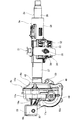
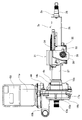
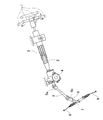
- FIG. 1 is a side view of an electric power steering apparatus according to a first example of the embodiment.
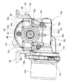
- FIG. 2 is a front view of the electric power steering apparatus according to the first example of the embodiment.
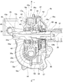
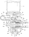
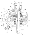
- FIG. 3 is a cross-sectional view of an essential part of the electric power steering apparatus according to the first example of the embodiment.
- FIG. 4 is a cross-sectional view taken along line AA of FIG.
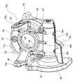
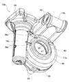
- FIG. 5 is a perspective view showing the front housing of the electric power steering apparatus according to the first example of the embodiment.
- FIG. 6 is a schematic view of a mold shown to explain a process of manufacturing the front housing of the first example of the embodiment by casting or injection molding.
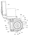
- FIG. 7 is a side view of an electric power steering apparatus according to a second example of the embodiment.
- FIG. 1 is a side view of an electric power steering apparatus according to a first example of the embodiment.
- FIG. 2 is a front view of the electric power steering apparatus according to the first example of the embodiment.
- FIG. 3 is a
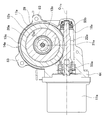
- FIG. 8 is a front view of an electric power steering apparatus according to a second example of the embodiment.
- FIG. 9 is a cross-sectional view of main parts of an electric power steering apparatus according to a second example of the embodiment.
- FIG. 10 is a cross-sectional view corresponding to FIG. 4 regarding the electric power steering apparatus according to the second example of the embodiment.
- FIG. 11 is a front view showing the front housing taken out of the electric power steering apparatus according to the second example of the embodiment.
- FIG. 12 is a perspective view showing the front housing of the electric power steering apparatus according to the second example of the embodiment.
- FIG. 13 is a partially cutaway side view showing an example of a conventional electric power steering apparatus.
- FIG. 14 is a cross-sectional view corresponding to FIG. 3 regarding the electric assist device of the conventional structure.
- the electric power steering apparatus includes a tilt / telescopic mechanism capable of adjusting the vertical position and the front / rear position of the steering wheel 1 (see FIG. 13) in accordance with the driver's physical constitution and driving posture;
- An electric assist device 4b is provided to reduce the force required for the operation.
- the steering shaft 2a is rotatably supported inside the steering column 3a via a plurality of rolling bearings (not shown).
- the steering wheel 1 is fixed to a portion of the rear end portion of the steering shaft 2a that protrudes rearward beyond the rear end opening of the steering column 3a.
- the steering shaft 2a includes an inner shaft 25 and an outer shaft 26, which can transmit a rotational force and allow relative displacement in the axial direction by spline engagement or the like.
- the inner shaft 25 and the outer shaft 26 are axially displaced relative to each other to adjust the longitudinal position of the steering wheel 1 and to reduce the overall length of the steering shaft 2a in the event of a collision.
- the steering column 3a has a hollow cylindrical shape as a whole, and includes an inner column 27 and an outer column 28. A front portion of the outer column 28 is fitted loosely to allow a relative displacement in the axial direction to a rear portion of the inner column 27 Have a structure that The steering column 3a has a function of enabling adjustment of the front-rear position of the steering wheel 1, and a function of shortening the total length of the steering column 3a together with the steering shaft 2a in the event of a collision.
- the gear housing 14a which comprises the electrically-driven assist apparatus 4b is fixed to the front end part (left end part of FIG. 1) of the inner column 27. As shown in FIG.
- the gear housing 14a is supported so as to be able to pivot about a tilt shaft 30 disposed in the width direction with respect to the lower bracket 29 fixed to the vehicle body.
- the width direction refers to the width direction of the vehicle body on which the electric power steering apparatus is assembled, and corresponds to the left-right direction.
- the outer column 28 is supported by the upper bracket 31 on the vehicle body.
- the upper bracket 31 is configured to be detachable forward from the vehicle body when a strong impact directed to the front is applied.
- the outer column 28 is supported movably in the front and rear direction and in the up and down direction with respect to the upper bracket 31, and the front and rear position and the up and down position of the steering wheel 1 can be adjusted.
- the pair of held portions 32 constituting the outer column 28 are provided with telescopic adjustment long holes 33 which are long in the front-rear direction.
- the pair of support plate portions 34 constituting the upper bracket 31 disposed on both sides in the width direction of the pair of held portions 32 are provided with long tilt adjustment long holes 35 in the vertical direction.
- the adjustment rod 36 is inserted in the width direction into the telescopic adjustment long hole 33 and the tilt adjustment long hole 35.
- a lever (not shown) fixed to the end of the adjustment rod 36 and expanding / contracting the expansion / contraction device (not shown) arranged around the adjustment rod 36 in the width direction, a pair of support plates 34 hold a pair of clamped
- the force holding the portion 32 from both sides in the width direction can be adjusted.
- the outer column 28 can be fixed to the upper bracket 31 or can be released from the fixing.
- the outer column 28 moves back and forth within the range in which the adjustment rod 36 can be displaced inside the telescopic adjustment long hole 33, and the longitudinal position of the steering wheel 1 can be adjusted. Further, the vertical position of the steering wheel 1 can be adjusted by vertically moving the steering column 3a within a range in which the adjusting rod 36 can be displaced inside the tilt adjusting long hole 35. At this time, the steering column 3 a swings in the vertical direction about the tilt shaft 30.
- An electric assist device 4b for reducing the operation force of the steering wheel 1 is disposed in front of the steering column 3a, and includes a torque sensor 10a, an electric motor 11a, a worm reduction gear 12a, an output shaft 13a, and a gear housing 14a. Equipped with
- the worm reduction gear 12a has a worm shaft 21a rotationally driven by the electric motor 11a, a worm 22a provided at an intermediate portion of the worm shaft 21a, and a worm wheel 20a meshing with the worm 22a.
- the gear housing 14a includes a front housing 15a and a rear housing 16a combined in the front-rear direction via an intermediate plate 37, and accommodates the worm reduction gear 12a inside.
- the front housing 15a and the rear housing 16a are both cast products (including die cast molded products) of light alloys such as iron-based alloys or aluminum alloys, or injection molded products of synthetic resin.
- the front housing 15a includes a worm wheel receiving portion 17a receiving the worm wheel 20a inside, a worm receiving portion 18a receiving the worm shaft 21a inside, and a plurality of (three in the illustrated example) reinforcing ribs 38a and 38b, And 38c.
- the worm wheel accommodating portion 17a has a cup shape opened at the rear and a central axis extending in a substantially horizontal direction.
- the worm wheel accommodating portion 17a is disposed around the worm wheel 20a, and is disposed forward of the worm wheel cylindrical portion 39 and the worm wheel 20a, and radially from the front end portion of the worm wheel cylindrical portion 39.
- an annular worm wheel bottom 40 bent substantially at a right angle toward the inside.
- the worm wheel bottom portion 40 is provided with a substantially cylindrical inner diameter side cylindrical portion 41 at an inner peripheral edge portion.
- the bottom portion 40 for the worm wheel is provided with a bearing holding hole 42 at a radially inner portion of the inner diameter side cylindrical portion 41 which is a radially central portion.
- the worm wheel bottom portion 40 is provided with an annular projection 43 at the opening edge portion on the front side of the bearing holding hole 42, which protrudes forward more than the radial direction intermediate portion and the outer portion of the worm wheel bottom portion 40.
- the annular projection 43 is constituted by the front end portion of the inner diameter side cylindrical portion 41.
- the worm accommodating portion 18a has a substantially bottomed cylindrical shape.
- the worm accommodating portion 18a is a part of the outer diameter side of the worm wheel accommodating portion 17a in the circumferential direction, and is disposed at a portion located below in the assembled state of the electric power steering apparatus.
- the internal space of the worm accommodating portion 18a communicates with the internal space of the worm wheel accommodating portion 17a.
- the worm accommodating portion 18a extends in a substantially horizontal direction, but has a central axis which is in a twisted positional relationship with the central axis of the worm wheel accommodating portion 17a.
- the worm accommodating portion 18 a includes a motor mounting flange 44 protruding radially outward at an opening side end.
- the gear housing 14a of this embodiment protrudes forward from the vertical middle portion of the front side surface of the bottom portion 40 for the worm wheel, and is a pair for supporting the gear housing 14a to be able to perform swing displacement on the vehicle body via the lower bracket 29.
- the mounting stay 19a is provided. Specifically, the pair of mounting stays 19a are arranged at positions mutually sandwiching the bearing holding holes 42 in the width direction of the vehicle body in the worm wheel bottom portion 40 of the front housing 15a, being mutually separated. .
- Each of the pair of mounting stays 19a has mounting holes 45 at its tip end, which pass through in the width direction and into which the tilt shaft 30 is inserted.
- the front half portion of the mounting stay 19a has a tapered shape in which the dimension in the vertical direction decreases toward the tip end, whereas the base half portion of the mounting stay 19a does not change in the dimension in the vertical direction. It has a shape that increases in size toward the proximal side (projects inward in the width direction).
- the widthwise outer surface of the base end portion of the mounting stay 19a is continuous with the outer peripheral surface of the worm wheel cylindrical portion 39, while the widthwise inner surface of the base end portion of the mounting stay 19a is annular projection 43 To be continuous. Further, the lower end portion of the widthwise outer surface of the mounting stay 19a positioned on the opening side (left side in FIGS.
- the pair of mounting stays 19 a is disposed between the pair of side plate portions 46 that constitute the lower bracket 29.
- Each of the three reinforcing ribs 38a, 38b and 38c is solid, has a thickness dimension in the front-rear direction larger than a portion present in the periphery, and on the front side surface of the front housing 15a, the worm accommodating portion 18a and the worm wheel It is arranged to be bridged with the bottom 40.
- the thickness dimension of the portion of the front housing 15a where the reinforcing ribs 38a, 38b and 38c are installed is the thickness of the portion of the front housing 15a which exists around the reinforcing ribs 38a, 38b and 38c. It is set sufficiently large within a range of, for example, 10 times or less of the dimension.
- the thickness dimension of the portion where the reinforcing ribs 38a, 38b, 38c are installed is set such that the reinforcing ribs 38a, 38b, 38c do not project axially from the annular projection 43 preferable.
- the reinforcing ribs 38a, 38b, and 38c are in the alignment direction of the worm wheel accommodating portion 17a and the worm accommodating portion 18a, and are the engagement reaction force between the worm wheel 20a and the worm 22a provided on the worm shaft 21a. It extends in the direction of action (vertical direction in FIGS. 2 and 4).
- the reinforcing ribs 38a, 38b, 38c are substantially parallel to the imaginary straight line L that is perpendicular to the central axis O 11a of the central axis O 20 and the electric motor 11a of the worm wheel 20a.
- substantially parallel includes the case where the forming direction of the reinforcing ribs 38a, 38b and 38c is inclined with respect to the imaginary straight line L due to a manufacturing error or an assembly error of the electric power steering apparatus. As will be described later, the extending direction of the reinforcing ribs 38a, 38b and 38c is inclined with respect to the imaginary straight line L as long as the rigidity of the front housing 15a against the engagement reaction force between the worm wheel 20a and the worm 22a can be improved. It can also be done.
- the angle between the extension direction of the reinforcing ribs 38a, 38b, 38c and the imaginary straight line L can be set to any angle of 45 degrees or less, that is, 0 degrees, that is, the reinforcing ribs 38a, 38b, 38c. It is preferable to make it parallel to the formation direction of and the imaginary straight line L. Further, the angle between the extension direction of the reinforcing ribs 38b and 38c and the virtual straight line Lto can be an arbitrary angle of 45 degrees or less, where the angle between the extension direction of the reinforcing rib 38a and the virtual straight line L is 0 degrees. .
- the meshing reaction force is a force acting in the opposite direction so that the worm wheel 20a and the worm shaft 21 are separated.
- the reinforcing ribs 38a, 38b and 38c are extended in the acting direction of the meshing reaction force, the rigidity of the front housing 15a with respect to the meshing reaction force can be effectively improved. For this reason, even when the front housing 15a is thinned, it is possible to prevent the occurrence of harmful deformation or the like due to the meshing reaction force in the front housing 15a.
- the reinforcing ribs 38a, 38b, and 38c have a cross-sectional shape such as a trapezoidal shape or a convex arc shape, in which the dimension in the width direction (short direction) decreases toward the front.
- a cross-sectional shape such as a trapezoidal shape or a convex arc shape, in which the dimension in the width direction (short direction) decreases toward the front.
- the reinforcing rib 38a installed at the widthwise intermediate portion is the lower end portion of the annular projection 43 closest to the worm accommodating portion 18a, and the axial intermediate intermediate portion of the worm accommodating portion 18a. It is arranged to be bridged with the department. Therefore, the upper end of the reinforcing rib 38 a is connected to the lower end of the annular projection 43.
- the two reinforcing ribs 38b and 38c installed on both sides in the width direction are bridged by the lower surface of the base end of the pair of mounting stays 19a and the two axial sides of the worm accommodating portion 18a. Will be placed.
- the upper ends of the reinforcing ribs 38b and 38c are connected to the lower surface of the base end of the mounting stay 19a. That is, the reinforcing ribs 38b and 38c and the pair of mounting stays 19a are arranged to be continuous in the vertical direction.
- the thickness dimension of the reinforcing rib 38a in the width direction is substantially constant over the entire length, while the thickness dimension in the width direction of the reinforcing ribs 38b and 38c approaches the mounting stay 19a. It is getting bigger.
- the front housing 15a is provided with a plurality of (three in the illustrated example) bosses 47 projecting forward relative to a portion present in the periphery at a plurality of locations on the front side.
- bosses 47 project more forward than the portions present around them, and are thus thicker.
- the two bosses 47 arranged at the outer peripheral edge of the worm wheel housing 17a are continuous with the reinforcing ribs 38b and 38c, respectively.
- the front housing 15a having the above-described configuration is produced by casting or injection molding using a mold (casting mold, injection molding mold) 60 having a cavity 61.
- the gate G for the mold 60 serving as a supply port for the material (molten metal, synthetic resin), a worm accommodation portion forming space 62 for forming the worm accommodation portion 18a.
- the gate G is disposed on the opposite side of the worm wheel accommodating portion forming space 63 for forming the worm wheel accommodating portion 17a. That is, the gate G is disposed such that the worm accommodating portion forming space 62 is on the upstream side.
- the material that has passed through the worm accommodating portion forming space 62 flows to the worm wheel accommodating portion forming space 63 side.
- the worm accommodating portion 18a is positioned upstream of the worm wheel accommodating portion 17a in the material flow direction.
- the rear housing 16 a is formed of a cast or a synthetic resin injection-molded article having a hollow cylindrical shape as a whole, and includes a fixed cylindrical portion 48, a large diameter cylindrical portion 49 and a continuous portion 50.
- the fixed cylindrical portion 48 has a cylindrical shape and is fixedly fitted to the front end portion of the inner column 27.
- the large diameter cylindrical portion 49 is disposed around the torque sensor 10 a and abuts on the rear end opening of the front housing 15 a via the intermediate plate 37.
- the continuous portion 50 connects the front end portion of the fixed cylindrical portion 48 and the rear end portion of the large diameter cylindrical portion 49.
- the front housing 15a and the rear housing 16a are connected to each other by a plurality of (three in the illustrated example) bolts 57 in a state where they are combined via the intermediate plate 37.
- the front fitting portion 51 provided on the outer diameter side portion of the front side surface of the intermediate plate 37 which is generally formed in a substantially annular shape
- the front housing 15a (cylindrical portion 39 for worm wheel
- the front end portion of the rear housing 16 large diameter cylindrical portion 49) is externally fitted to the rear fitting portion 52 provided on the outer diameter side portion of the rear side.
- a plurality of (three in the illustrated example) rear coupling flanges 58 formed on the outer peripheral surface are coupled to one another by bolts 57, respectively.
- the output shaft 13a is rotatably supported by the pair of rolling bearings 54a and 54b inside the gear housing 14a having the above-described configuration.
- the rolling bearing 54a on the front side is internally fitted and held in the bearing holding hole 42 constituting the front housing 15a, and the rolling bearing 54b on the rear side is on the inner circumferential surface of the intermediate plate 37. Internally held.
- the outer ring forming the front side rolling bearing 54 a is fitted and fixed to the axially intermediate portion of the inner peripheral surface of the bearing holding hole 42 by press-fitting.
- the outer ring constituting the rolling bearing 54 a on the front side is provided at a portion near the front end of the bearing holding hole 42 and is formed at a step surface facing rearward and a portion near the rear end of the inner circumferential surface of the bearing holding hole 42 It is clamped from both sides by the snap ring locked by the locking groove.
- the output shaft 13a is coupled to the front end portion of the inner shaft 25 constituting the steering shaft 2a via a torsion bar 24a.
- a universal joint 5a (see FIG. 13) is coupled to a portion of the front end portion of the output shaft 13a that protrudes to the outside of the gear housing 14a.
- a worm wheel 20a constituting the worm reduction gear 12a is externally fitted and fixed between the pair of rolling bearings 54a and 54b. In this state, the worm wheel 20a is disposed inside the worm wheel receiving portion 17a that constitutes the front housing 15a.
- the worm shaft 21a constituting the worm reduction gear 12a is rotatably supported inside the worm accommodating portion 18a via a pair of rolling bearings 55a and 55b.
- the worm 22a provided at the middle portion of the worm shaft 21a meshes with the worm wheel 20a.
- the output shaft of the electric motor 11a is connected to the proximal end of the worm shaft 21a. Thereby, the auxiliary power of the electric motor 11a can be transmitted to the worm wheel 20a.
- the electric motor 11a is supported and fixed to the gear housing 14a via a motor mounting flange 44 that constitutes the front housing 15a.
- the tip end of the worm shaft 21a is directed to the worm wheel 20a side between the rolling bearing 55a externally fitted to the tip end of the worm shaft 21a and the inner peripheral surface of the worm accommodating portion 18a.
- a torque sensor 10a is disposed around the front end of the inner shaft 25 inside the large diameter cylindrical portion 49 that constitutes the rear housing 16a.
- the electric motor 11a rotationally drives the worm shaft 21a according to the direction and the magnitude of the steering torque applied from the steering wheel 1 to the steering shaft 2a detected by the torque sensor 10a, and the auxiliary power (assist torque Give).
- the operation force of the steering wheel 1, which is necessary when giving the steering angle to the pair of left and right steered wheels is reduced.
- rigidity can be secured even when thinning the front housing 15a constituting the gear housing 14a, and formability at the time of manufacture is secured. it can. That is, in the present embodiment, reinforcing ribs 38a, 38b, 38c are arranged on the front side of the front housing 15a so as to bridge between the worm accommodating portion 18a and the worm wheel bottom 40 and the reinforcing ribs 38a, The extending directions of 38b and 38c are made to coincide with the acting direction of the meshing reaction force between the worm wheel 20a and the worm 22a. Therefore, the rigidity of the front housing 15a against the engagement reaction force can be effectively improved. Therefore, even when the front housing 15a is thinned, the occurrence of harmful deformation or the like due to the meshing reaction force is prevented in the front housing 15a.
- the reinforcing ribs 38a, 38b and 38c are made with respect to the cavity 61 of the mold 60 used when producing the front side housing 15a by casting or injection molding.
- the cross-sectional area of the space through which the material flows can be increased by the space for forming.
- the extending direction of the reinforcing ribs 38a, 38b, 38c is the same as the acting direction of the meshing reaction force directed in the arrangement direction of the worm wheel accommodating portion 17a and the worm accommodating portion 18a, the material shown in FIG.
- the material supplied from the gate G is efficiently supplied to the worm wheel container forming space 63 through the space for forming the reinforcing ribs 38a, 38b and 38c in the cavity 61, as indicated by the arrows in FIG. be able to.
- the flowability (flowability of the material) of the material can be improved, and the formability at the time of manufacture can be improved.
- a material is formed in the space for forming the mounting stay 19a through the space for forming the reinforcing ribs 38b and 38c. It can be supplied directly. Therefore, the material can be sufficiently supplied to the space for forming the mounting stay 19a, and the strength and rigidity of the mounting stay 19a can be improved. Also, the material can be directly supplied to the space for forming the inner diameter side cylindrical portion 41, particularly to the portion for forming the annular projection 43 in the space, through the space for forming the reinforcing rib 38a. . Therefore, according to this embodiment, the deterioration of the quality of the front housing 15a is prevented.
- the rigidity can be secured, and the formability at the time of manufacture can be secured, so weight reduction by thinning can be achieved.
- the rigidity of the front housing 15a and the rigidity of the mounting stay 19a can be improved. Therefore, the operation feeling and operation efficiency of the electric power steering apparatus can be improved, and the generation of vibration and noise can be suppressed. Further, since the rigidity of the mounting stay 19a can be improved, the behavior of the contraction operation of the steering shaft 2a and the steering column 3a can be stabilized, and the absorption characteristic of collision energy can also be improved.
- the front housing 15a includes the three reinforcing ribs 38a, 38b, and 38c. However, even when only one reinforcing rib is provided, the above-described operation and effects of the present invention can be achieved.
- the number, installation position, and shape of the reinforcing ribs are arbitrarily and appropriately selected from the viewpoint of securing the rigidity of the front housing and the arrangement and shape of the parts constituting the front housing, the flow of materials at the time of production thereof, and the rigidity of the front housing. Be done.
- the structure of the front housing 15b is changed from the structure of the first example of the embodiment.
- the worm accommodating portion 18b is a part of the outer diameter side of the worm wheel accommodating portion 17a in the circumferential direction, and in the assembled state of the electric power steering apparatus, the output shaft 13a It is arranged in a laterally located part. For this reason, the central axis of the worm accommodating portion 18b is directed in the vertical direction. Further, the opening of the worm accommodating portion 18b is directed upward in the assembled state of the electric power steering apparatus.
- the bottom portion 40 for the worm wheel is provided with one mounting stay 19b having a shape in which the pair of mounting stays 19a shown in the first example of the embodiment are continued in the width direction at the upper end portion of the front side surface.
- the widthwise outer side surface of the mounting stay 19b is continuous with the widthwise side surface of the motor mounting flange 44 provided at the open end of the worm housing 18b.
- the motor mounting flange 44 supports the electric motor 11 a and the control device 59 which incorporates a substrate.
- the bottom portion 40 for the worm wheel has two reinforcing ribs 38a, 38d on the front side surface, corresponding to the change in the arrangement of the worm accommodating portion 18b and the change in the shape of the mounting stay 19b.
- the reinforcing rib 38a is disposed so as to bridge the end of the annular projection 43 closest to the worm accommodating portion 18b and the vertically intermediate portion of the worm accommodating portion 18b, and the mounting stay
- a reinforcing rib 38d is disposed so as to bridge the widthwise outer surface of the proximal end portion 19b and a portion near the upper end of the worm accommodating portion 18b.
- the mounting stay is not disposed at a portion corresponding to the portion closer to the lower end of the worm accommodating portion 18b, so only two reinforcing ribs 38a and 38d are provided as described above.
- the reinforcing ribs 38a and 38d extend in the acting direction of the meshing reaction force between the worm wheel 20a and the worm 22a.
- the gear housing 14b is configured by combining the front housing 15b and the rear housing 16b directly in the front-rear direction without the intermediate plate.
- the rear housing 16 b includes a fixed cylindrical portion 48 fixed to the front end of the inner column 27 and an annular cover 56 bent radially outward from the front end of the fixed cylindrical portion 48.
- the lid 56 closes the rear end opening of the front housing 15b.
- the rigidity of the front housing 15b with respect to the engagement reaction force can be effectively improved.
- the material can be efficiently supplied to the space for forming the worm wheel receiving portion 17a (in particular, the space for forming the mounting stay 19b) through the spaces for forming the reinforcing ribs 38a and 38d. Therefore, the rigidity can be secured and the formability at the time of manufacture can be secured even when the front housing 15b constituting the gear housing 14b is to be thinned.
- Other configurations and effects are the same as the first example of the embodiment.
Landscapes
- Engineering & Computer Science (AREA)
- Mechanical Engineering (AREA)
- Chemical & Material Sciences (AREA)
- Combustion & Propulsion (AREA)
- Transportation (AREA)
- Power Steering Mechanism (AREA)
- Molds, Cores, And Manufacturing Methods Thereof (AREA)
- Moulds For Moulding Plastics Or The Like (AREA)
Priority Applications (4)
| Application Number | Priority Date | Filing Date | Title |
|---|---|---|---|
| JP2019550304A JP6911933B2 (ja) | 2017-10-30 | 2018-10-25 | 電動パワーステアリング装置用ギヤハウジングおよび電動パワーステアリング装置 |
| EP18873158.2A EP3705375B1 (en) | 2017-10-30 | 2018-10-25 | Gear housing for electric power steering device, manufacturing method thereof, and electric power steering device |
| US16/758,483 US11377138B2 (en) | 2017-10-30 | 2018-10-25 | Gear housing for electric power steering device, manufacturing method thereof, and electric power steering device |
| CN201880067542.7A CN111247050B (zh) | 2017-10-30 | 2018-10-25 | 电动助力转向装置用齿轮箱及其制造方法、电动助力转向装置 |
Applications Claiming Priority (2)
| Application Number | Priority Date | Filing Date | Title |
|---|---|---|---|
| JP2017209665 | 2017-10-30 | ||
| JP2017-209665 | 2017-10-30 |
Publications (1)
| Publication Number | Publication Date |
|---|---|
| WO2019087945A1 true WO2019087945A1 (ja) | 2019-05-09 |
Family
ID=66331970
Family Applications (1)
| Application Number | Title | Priority Date | Filing Date |
|---|---|---|---|
| PCT/JP2018/039780 Ceased WO2019087945A1 (ja) | 2017-10-30 | 2018-10-25 | 電動パワーステアリング装置用ギヤハウジングおよびその製造方法、並びに、電動パワーステアリング装置 |
Country Status (5)
| Country | Link |
|---|---|
| US (1) | US11377138B2 (enExample) |
| EP (1) | EP3705375B1 (enExample) |
| JP (2) | JP6911933B2 (enExample) |
| CN (1) | CN111247050B (enExample) |
| WO (1) | WO2019087945A1 (enExample) |
Cited By (2)
| Publication number | Priority date | Publication date | Assignee | Title |
|---|---|---|---|---|
| KR20220017044A (ko) * | 2020-08-03 | 2022-02-11 | (주)케이에이씨 | 차량용 웜하우징 |
| WO2023074304A1 (ja) | 2021-10-25 | 2023-05-04 | 日本精工株式会社 | ギヤハウジングおよび電動アシスト装置 |
Families Citing this family (3)
| Publication number | Priority date | Publication date | Assignee | Title |
|---|---|---|---|---|
| DE102019212213A1 (de) * | 2019-08-14 | 2021-02-18 | Volkswagen Aktiengesellschaft | Zahnstangen-Lenkung sowie Kraftfahrzeug mit einer solchen Zahnstangen-Lenkung |
| CN112517882B (zh) * | 2020-12-22 | 2022-09-20 | 荆州荆龙汽车零部件科技有限公司 | 一种转向器壳体的压铸模具 |
| CN115401182A (zh) * | 2022-09-23 | 2022-11-29 | 荆州荆龙航天科技有限公司 | 一种转向器壳体及其压铸加工方法 |
Citations (4)
| Publication number | Priority date | Publication date | Assignee | Title |
|---|---|---|---|---|
| JP2002517694A (ja) * | 1998-06-11 | 2002-06-18 | プレシジョン プロダクツ システムズ, エルエルシー | ギヤハウジング |
| JP2012020647A (ja) * | 2010-07-14 | 2012-02-02 | Jtekt Corp | 電動パワーステアリング装置 |
| WO2016084659A1 (ja) | 2014-11-25 | 2016-06-02 | 日本精工株式会社 | 電動式パワーステアリング装置用ハウジング |
| JP2017024702A (ja) * | 2015-04-16 | 2017-02-02 | 日本精工株式会社 | 減速機及び電動式パワーステアリング装置 |
Family Cites Families (6)
| Publication number | Priority date | Publication date | Assignee | Title |
|---|---|---|---|---|
| US6628026B2 (en) * | 2000-03-30 | 2003-09-30 | Asmo Co., Ltd. | Geared motor including ribbed gear housing |
| JP2003072562A (ja) * | 2001-08-30 | 2003-03-12 | Koyo Seiko Co Ltd | 電動式動力舵取装置 |
| JP2012176632A (ja) * | 2011-02-25 | 2012-09-13 | Nsk Ltd | 電動パワーステアリング装置 |
| JP2015013638A (ja) * | 2013-06-03 | 2015-01-22 | 株式会社ジェイテクト | 電動パワーステアリング装置 |
| JP2015094375A (ja) * | 2013-11-08 | 2015-05-18 | 株式会社ジェイテクト | 減速装置 |
| CN107284515A (zh) * | 2017-06-14 | 2017-10-24 | 奇瑞汽车股份有限公司 | 转向系统的助力装置 |
-
2018
- 2018-10-25 CN CN201880067542.7A patent/CN111247050B/zh active Active
- 2018-10-25 WO PCT/JP2018/039780 patent/WO2019087945A1/ja not_active Ceased
- 2018-10-25 US US16/758,483 patent/US11377138B2/en active Active
- 2018-10-25 EP EP18873158.2A patent/EP3705375B1/en active Active
- 2018-10-25 JP JP2019550304A patent/JP6911933B2/ja active Active
-
2021
- 2021-02-12 JP JP2021021296A patent/JP7099567B2/ja active Active
Patent Citations (4)
| Publication number | Priority date | Publication date | Assignee | Title |
|---|---|---|---|---|
| JP2002517694A (ja) * | 1998-06-11 | 2002-06-18 | プレシジョン プロダクツ システムズ, エルエルシー | ギヤハウジング |
| JP2012020647A (ja) * | 2010-07-14 | 2012-02-02 | Jtekt Corp | 電動パワーステアリング装置 |
| WO2016084659A1 (ja) | 2014-11-25 | 2016-06-02 | 日本精工株式会社 | 電動式パワーステアリング装置用ハウジング |
| JP2017024702A (ja) * | 2015-04-16 | 2017-02-02 | 日本精工株式会社 | 減速機及び電動式パワーステアリング装置 |
Non-Patent Citations (1)
| Title |
|---|
| See also references of EP3705375A4 |
Cited By (4)
| Publication number | Priority date | Publication date | Assignee | Title |
|---|---|---|---|---|
| KR20220017044A (ko) * | 2020-08-03 | 2022-02-11 | (주)케이에이씨 | 차량용 웜하우징 |
| KR102381668B1 (ko) * | 2020-08-03 | 2022-04-06 | (주)케이에이씨 | 차량용 웜하우징 |
| WO2023074304A1 (ja) | 2021-10-25 | 2023-05-04 | 日本精工株式会社 | ギヤハウジングおよび電動アシスト装置 |
| US12466467B2 (en) | 2021-10-25 | 2025-11-11 | Nsk Steering & Control, Inc. | Gear housing and electric assist device |
Also Published As
| Publication number | Publication date |
|---|---|
| JP6911933B2 (ja) | 2021-07-28 |
| EP3705375B1 (en) | 2022-08-24 |
| CN111247050A (zh) | 2020-06-05 |
| EP3705375A4 (en) | 2021-10-27 |
| CN111247050B (zh) | 2022-05-03 |
| US20200255057A1 (en) | 2020-08-13 |
| JPWO2019087945A1 (ja) | 2020-10-22 |
| JP2021073137A (ja) | 2021-05-13 |
| EP3705375A1 (en) | 2020-09-09 |
| JP7099567B2 (ja) | 2022-07-12 |
| US11377138B2 (en) | 2022-07-05 |
Similar Documents
| Publication | Publication Date | Title |
|---|---|---|
| JP7099567B2 (ja) | 電動パワーステアリング装置用ギヤハウジングの製造方法 | |
| JP2021073137A5 (enExample) | ||
| JP7103455B2 (ja) | 電動パワーステアリング装置用ギヤハウジングの製造方法 | |
| JP4277798B2 (ja) | 電動パワーステアリング装置 | |
| JP2021073138A5 (enExample) | ||
| KR101488016B1 (ko) | 자동차 시트 슬라이딩 장치의 기어박스 | |
| JP3698605B2 (ja) | 電動パワーステアリング装置 | |
| JP2007309512A (ja) | ウォームホイール、ウォーム減速機構、電動式パワーステアリング装置及びウォームホイールの製造方法 | |
| JP5970992B2 (ja) | 電動パワーステアリング装置 | |
| JP2001141033A (ja) | ウォームホイール及びその製造方法 | |
| CN206900466U (zh) | 齿轮齿条副式转向齿轮单元用壳体 | |
| JP2011046310A (ja) | 車両用操舵装置 | |
| JP6402617B2 (ja) | 電動パワーステアリング装置 | |
| JP5970989B2 (ja) | 電動パワーステアリング装置 | |
| JP5966700B2 (ja) | 電動パワーステアリング装置 | |
| JP5970991B2 (ja) | 電動パワーステアリング装置 | |
| JP2023104054A (ja) | ギヤハウジングおよび電動アシスト装置 | |
| JP4640435B2 (ja) | ステアリング装置 | |
| JP2009073379A (ja) | ラックアンドピニオン式ステアリング装置 | |
| JPH11291920A (ja) | 電動パワーステアリング装置 | |
| JP2024053983A (ja) | ステアリング装置 | |
| JPH11294544A (ja) | ウォームホイールおよびその製造方法 | |
| JP2006192965A (ja) | ステアリング装置 |
Legal Events
| Date | Code | Title | Description |
|---|---|---|---|
| 121 | Ep: the epo has been informed by wipo that ep was designated in this application |
Ref document number: 18873158 Country of ref document: EP Kind code of ref document: A1 |
|
| ENP | Entry into the national phase |
Ref document number: 2019550304 Country of ref document: JP Kind code of ref document: A |
|
| NENP | Non-entry into the national phase |
Ref country code: DE |
|
| ENP | Entry into the national phase |
Ref document number: 2018873158 Country of ref document: EP Effective date: 20200602 |