WO2019087945A1 - Gear housing for electric power steering device, manufacturing method thereof, and electric power steering device - Google Patents
Gear housing for electric power steering device, manufacturing method thereof, and electric power steering device Download PDFInfo
- Publication number
- WO2019087945A1 WO2019087945A1 PCT/JP2018/039780 JP2018039780W WO2019087945A1 WO 2019087945 A1 WO2019087945 A1 WO 2019087945A1 JP 2018039780 W JP2018039780 W JP 2018039780W WO 2019087945 A1 WO2019087945 A1 WO 2019087945A1
- Authority
- WO
- WIPO (PCT)
- Prior art keywords
- worm
- worm wheel
- electric power
- power steering
- housing
- Prior art date
Links
Images


Classifications
-
- B—PERFORMING OPERATIONS; TRANSPORTING
- B62—LAND VEHICLES FOR TRAVELLING OTHERWISE THAN ON RAILS
- B62D—MOTOR VEHICLES; TRAILERS
- B62D5/00—Power-assisted or power-driven steering
- B62D5/04—Power-assisted or power-driven steering electrical, e.g. using an electric servo-motor connected to, or forming part of, the steering gear
- B62D5/0442—Conversion of rotational into longitudinal movement
- B62D5/0454—Worm gears
-
- B—PERFORMING OPERATIONS; TRANSPORTING
- B62—LAND VEHICLES FOR TRAVELLING OTHERWISE THAN ON RAILS
- B62D—MOTOR VEHICLES; TRAILERS
- B62D5/00—Power-assisted or power-driven steering
- B62D5/04—Power-assisted or power-driven steering electrical, e.g. using an electric servo-motor connected to, or forming part of, the steering gear
- B62D5/0403—Power-assisted or power-driven steering electrical, e.g. using an electric servo-motor connected to, or forming part of, the steering gear characterised by constructional features, e.g. common housing for motor and gear box
-
- B—PERFORMING OPERATIONS; TRANSPORTING
- B22—CASTING; POWDER METALLURGY
- B22C—FOUNDRY MOULDING
- B22C9/00—Moulds or cores; Moulding processes
- B22C9/22—Moulds for peculiarly-shaped castings
- B22C9/24—Moulds for peculiarly-shaped castings for hollow articles
-
- B—PERFORMING OPERATIONS; TRANSPORTING
- B62—LAND VEHICLES FOR TRAVELLING OTHERWISE THAN ON RAILS
- B62D—MOTOR VEHICLES; TRAILERS
- B62D1/00—Steering controls, i.e. means for initiating a change of direction of the vehicle
- B62D1/02—Steering controls, i.e. means for initiating a change of direction of the vehicle vehicle-mounted
- B62D1/16—Steering columns
- B62D1/18—Steering columns yieldable or adjustable, e.g. tiltable
- B62D1/187—Steering columns yieldable or adjustable, e.g. tiltable with tilt adjustment; with tilt and axial adjustment
- B62D1/189—Steering columns yieldable or adjustable, e.g. tiltable with tilt adjustment; with tilt and axial adjustment the entire column being tiltable as a unit
-
- B—PERFORMING OPERATIONS; TRANSPORTING
- B62—LAND VEHICLES FOR TRAVELLING OTHERWISE THAN ON RAILS
- B62D—MOTOR VEHICLES; TRAILERS
- B62D5/00—Power-assisted or power-driven steering
- B62D5/04—Power-assisted or power-driven steering electrical, e.g. using an electric servo-motor connected to, or forming part of, the steering gear
- B62D5/0409—Electric motor acting on the steering column
Definitions
- the present invention relates to an electric power steering apparatus, and more particularly to a gear housing for an electric power steering apparatus for housing a worm reduction gear that constitutes the electric power steering apparatus.
- FIG. 13 shows an example of a conventional structure of an electric power steering apparatus.
- the electric power steering apparatus includes a steering shaft 2 and a cylindrical steering column 3 rotatably supporting the steering shaft 2 inward, and auxiliary power for reducing the force required for the driver to operate the steering wheel 1.
- a universal joint 5a, an intermediate shaft 6, and a universal joint 5b for transmitting the rotation of the steering shaft 2 to the pinion shaft 8 of the steering gear unit 7 are provided.
- the steering wheel 1 is fixed to the rear end of the steering shaft 2. The movement of the steering wheel 1 at the time of steering is transmitted to the pinion shaft 8 via the steering shaft 2, the electric assist device 4, the universal joint 5a, the intermediate shaft 6, and the universal joint 5b.
- the rotation of the pinion shaft 8 pushes and pulls the pair of tie rods 9 arranged on both sides of the steering gear unit 7, and a steering angle according to the amount of operation of the steering wheel 1 is given to the pair of left and right steered wheels.
- the front-rear direction refers to the front-rear direction of the vehicle body on which the electric power steering apparatus is assembled.
- FIG. 14 shows a specific structure of the electric assist device described in WO 2016/084659.
- the electric assist device 4a is disposed in front of the steering column 3, and controls the energization based on measurement signals from the torque sensor 10 and the torque sensor 10 that measure the steering torque input from the steering wheel 1 to the steering shaft 2. It is fixed to the front end of the electric motor 11 and the worm reduction gear 12 which applies the auxiliary power from the electric motor 11 to the output shaft 13 to generate the auxiliary power in a fixed state, the torque sensor 10 and the worm A gear housing 14 is provided to accommodate the reduction gear 12.
- the gear housing 14 includes a front housing 15 and a rear housing 16 disposed in the front-rear direction and coupled by a plurality of bolts.
- the front housing 15 is a cylindrical worm disposed at a part in the circumferential direction (upper end in the illustrated example) of the cup-shaped worm wheel accommodating portion 17 whose rear is open and the outer diameter side portion of the worm wheel accommodating portion 17 And a housing portion 18.
- the worm wheel accommodating portion 17 is provided with a mounting stay 19 which protrudes forward and supports the gear housing 14 with respect to the vehicle body.
- the worm reduction gear 12 includes a worm wheel 20 externally fitted and fixed to the output shaft 13 and a worm shaft 21 coupled to the output shaft of the electric motor 11.
- the worm wheel 20 is accommodated inside the worm wheel accommodating portion 17.
- the worm shaft 21 is accommodated inside the worm accommodating portion 18.
- the worm shaft 21 includes a worm 22 at an intermediate portion thereof, and the worm 22 and the worm wheel 20 mesh with each other.
- the output shaft 13 is rotatably supported in the gear housing 14, and is connected to the input shaft 23 coaxially disposed with each other via a torsion bar 24.
- the front end portion of the output shaft 13 is connected to the pinion shaft 8 through a pair of universal joints 5a, 5b and an intermediate shaft 6, as shown in FIG.
- the rear end of the input shaft 23 is connected to the front end of the steering shaft 2.
- the input shaft 23 and the output shaft 13 twist the torsion bar 24 by the steering torque applied to the input shaft 23 via the steering shaft 2 and the resistance to the rotation of the output shaft 13. Relative to the rotational direction while being elastically deformed.
- the relative displacement between the input shaft 23 and the output shaft 13 is measured by the torque sensor 10.
- a controller (not shown) controls the electric motor 11 according to the measurement signal of the torque sensor 10, and the auxiliary power (auxiliary torque) from the electric motor 11 is applied to the output shaft 13 via the worm reduction gear 12. .
- the gear housing is a cast product or an injection-molded product
- the front housing is provided with a mounting stay having a large amount of forward protrusion, there is a possibility that the space for forming the mounting stay may not be sufficiently supplied with the material.
- thinning of the gear housing has problems such as the deterioration of the quality and the reduction of the product strength.
- An object of the present invention is to provide a gear for an electric power steering apparatus, which can ensure rigidity even when it is thinned and can ensure formability (flowability of material) at the time of manufacture. It is about realizing the structure of a housing.
- the gear housing for an electric power steering apparatus constitutes an electric power steering apparatus, and includes a front housing and a rear housing which are combined in the front-rear direction directly or through other members such as an intermediate plate. Prepare.
- the front side housing includes a worm wheel receiving portion for receiving a worm wheel inside, a worm receiving portion for receiving a worm shaft inside, and one or more reinforcing ribs.
- the worm wheel accommodating portion has a worm wheel cylindrical portion disposed around the worm wheel, and a circular worm wheel bottom portion bent radially inward from a front end portion of the worm wheel cylindrical portion. .
- the worm accommodating portion is provided on a part of the outer diameter side of the worm wheel accommodating portion in the circumferential direction.
- the reinforcing rib is provided on the front side surface of the front housing, extends in the acting direction of the engagement reaction force between the worm wheel and the worm provided on the worm shaft, and the worm accommodating portion and the worm wheel bottom portion To be
- At least one reinforcing rib extending in the acting direction of the meshing reaction force is provided on the front side surface of the front housing, and the worm housing portion and the worm wheel bottom portion
- the front housing is provided at any other position on the front side of the front housing, for example, at a portion diametrically opposite to the portion where the reinforcing rib is installed, It is also possible to provide a rib (thick portion) having a large thickness dimension.
- An attachment stay may be further provided which protrudes forward from the worm wheel bottom and supports the front housing on a vehicle body.
- at least one reinforcing rib of the one or more reinforcing ribs can be continued to the mounting stay.
- the bottom portion for the worm wheel has a bearing holding hole at the radial center portion, and an annular ring protruding forward from the radially intermediate portion and the outer portion of the bottom portion for the worm wheel at the opening edge of the bearing holding hole.
- a protrusion can be provided.
- the front side surface of at least one of the one or more reinforcing ribs is disposed at the same position as the front side surface of the annular projection, or behind the front side surface of the annular projection It can be done.
- at least one reinforcing rib of the one or more reinforcing ribs is bridged between a portion of the annular projection closest to the worm housing and the worm housing. I can talk.
- the front housing may further include, on the front side, at least one boss projecting forward than a portion present in the periphery.
- the electric power steering apparatus comprises a worm reduction gear having a worm shaft rotationally driven by an electric motor, a worm provided at an intermediate portion of the worm shaft, and a worm wheel meshing with the worm.
- a gear housing is provided for receiving the worm reduction gear inside.
- the gear housing is configured by the gear housing for the electric power steering apparatus of the present invention.
- the front housing is manufactured by injection molding of cast or synthetic resin using a mold having a cavity. At this time, the material is made to flow from the side of the worm accommodating portion forming space for forming the worm accommodating portion to the worm wheel accommodating portion forming space for forming the worm wheel accommodating portion in the cavity.
- the rigidity can be secured and the formability at the time of manufacture can be secured, even when thinning the front housing.
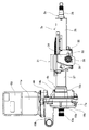
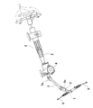
- FIG. 1 is a side view of an electric power steering apparatus according to a first example of the embodiment.
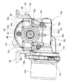
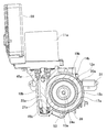
- FIG. 2 is a front view of the electric power steering apparatus according to the first example of the embodiment.
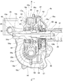
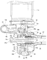
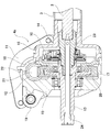
- FIG. 3 is a cross-sectional view of an essential part of the electric power steering apparatus according to the first example of the embodiment.
- FIG. 4 is a cross-sectional view taken along line AA of FIG.
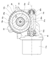
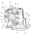
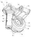
- FIG. 5 is a perspective view showing the front housing of the electric power steering apparatus according to the first example of the embodiment.
- FIG. 6 is a schematic view of a mold shown to explain a process of manufacturing the front housing of the first example of the embodiment by casting or injection molding.
- FIG. 7 is a side view of an electric power steering apparatus according to a second example of the embodiment.
- FIG. 1 is a side view of an electric power steering apparatus according to a first example of the embodiment.
- FIG. 2 is a front view of the electric power steering apparatus according to the first example of the embodiment.
- FIG. 3 is a
- FIG. 8 is a front view of an electric power steering apparatus according to a second example of the embodiment.
- FIG. 9 is a cross-sectional view of main parts of an electric power steering apparatus according to a second example of the embodiment.
- FIG. 10 is a cross-sectional view corresponding to FIG. 4 regarding the electric power steering apparatus according to the second example of the embodiment.
- FIG. 11 is a front view showing the front housing taken out of the electric power steering apparatus according to the second example of the embodiment.
- FIG. 12 is a perspective view showing the front housing of the electric power steering apparatus according to the second example of the embodiment.
- FIG. 13 is a partially cutaway side view showing an example of a conventional electric power steering apparatus.
- FIG. 14 is a cross-sectional view corresponding to FIG. 3 regarding the electric assist device of the conventional structure.
- the electric power steering apparatus includes a tilt / telescopic mechanism capable of adjusting the vertical position and the front / rear position of the steering wheel 1 (see FIG. 13) in accordance with the driver's physical constitution and driving posture;
- An electric assist device 4b is provided to reduce the force required for the operation.
- the steering shaft 2a is rotatably supported inside the steering column 3a via a plurality of rolling bearings (not shown).
- the steering wheel 1 is fixed to a portion of the rear end portion of the steering shaft 2a that protrudes rearward beyond the rear end opening of the steering column 3a.
- the steering shaft 2a includes an inner shaft 25 and an outer shaft 26, which can transmit a rotational force and allow relative displacement in the axial direction by spline engagement or the like.
- the inner shaft 25 and the outer shaft 26 are axially displaced relative to each other to adjust the longitudinal position of the steering wheel 1 and to reduce the overall length of the steering shaft 2a in the event of a collision.
- the steering column 3a has a hollow cylindrical shape as a whole, and includes an inner column 27 and an outer column 28. A front portion of the outer column 28 is fitted loosely to allow a relative displacement in the axial direction to a rear portion of the inner column 27 Have a structure that The steering column 3a has a function of enabling adjustment of the front-rear position of the steering wheel 1, and a function of shortening the total length of the steering column 3a together with the steering shaft 2a in the event of a collision.
- the gear housing 14a which comprises the electrically-driven assist apparatus 4b is fixed to the front end part (left end part of FIG. 1) of the inner column 27. As shown in FIG.
- the gear housing 14a is supported so as to be able to pivot about a tilt shaft 30 disposed in the width direction with respect to the lower bracket 29 fixed to the vehicle body.
- the width direction refers to the width direction of the vehicle body on which the electric power steering apparatus is assembled, and corresponds to the left-right direction.
- the outer column 28 is supported by the upper bracket 31 on the vehicle body.
- the upper bracket 31 is configured to be detachable forward from the vehicle body when a strong impact directed to the front is applied.
- the outer column 28 is supported movably in the front and rear direction and in the up and down direction with respect to the upper bracket 31, and the front and rear position and the up and down position of the steering wheel 1 can be adjusted.
- the pair of held portions 32 constituting the outer column 28 are provided with telescopic adjustment long holes 33 which are long in the front-rear direction.
- the pair of support plate portions 34 constituting the upper bracket 31 disposed on both sides in the width direction of the pair of held portions 32 are provided with long tilt adjustment long holes 35 in the vertical direction.
- the adjustment rod 36 is inserted in the width direction into the telescopic adjustment long hole 33 and the tilt adjustment long hole 35.
- a lever (not shown) fixed to the end of the adjustment rod 36 and expanding / contracting the expansion / contraction device (not shown) arranged around the adjustment rod 36 in the width direction, a pair of support plates 34 hold a pair of clamped
- the force holding the portion 32 from both sides in the width direction can be adjusted.
- the outer column 28 can be fixed to the upper bracket 31 or can be released from the fixing.
- the outer column 28 moves back and forth within the range in which the adjustment rod 36 can be displaced inside the telescopic adjustment long hole 33, and the longitudinal position of the steering wheel 1 can be adjusted. Further, the vertical position of the steering wheel 1 can be adjusted by vertically moving the steering column 3a within a range in which the adjusting rod 36 can be displaced inside the tilt adjusting long hole 35. At this time, the steering column 3 a swings in the vertical direction about the tilt shaft 30.
- An electric assist device 4b for reducing the operation force of the steering wheel 1 is disposed in front of the steering column 3a, and includes a torque sensor 10a, an electric motor 11a, a worm reduction gear 12a, an output shaft 13a, and a gear housing 14a. Equipped with
- the worm reduction gear 12a has a worm shaft 21a rotationally driven by the electric motor 11a, a worm 22a provided at an intermediate portion of the worm shaft 21a, and a worm wheel 20a meshing with the worm 22a.
- the gear housing 14a includes a front housing 15a and a rear housing 16a combined in the front-rear direction via an intermediate plate 37, and accommodates the worm reduction gear 12a inside.
- the front housing 15a and the rear housing 16a are both cast products (including die cast molded products) of light alloys such as iron-based alloys or aluminum alloys, or injection molded products of synthetic resin.
- the front housing 15a includes a worm wheel receiving portion 17a receiving the worm wheel 20a inside, a worm receiving portion 18a receiving the worm shaft 21a inside, and a plurality of (three in the illustrated example) reinforcing ribs 38a and 38b, And 38c.
- the worm wheel accommodating portion 17a has a cup shape opened at the rear and a central axis extending in a substantially horizontal direction.
- the worm wheel accommodating portion 17a is disposed around the worm wheel 20a, and is disposed forward of the worm wheel cylindrical portion 39 and the worm wheel 20a, and radially from the front end portion of the worm wheel cylindrical portion 39.
- an annular worm wheel bottom 40 bent substantially at a right angle toward the inside.
- the worm wheel bottom portion 40 is provided with a substantially cylindrical inner diameter side cylindrical portion 41 at an inner peripheral edge portion.
- the bottom portion 40 for the worm wheel is provided with a bearing holding hole 42 at a radially inner portion of the inner diameter side cylindrical portion 41 which is a radially central portion.
- the worm wheel bottom portion 40 is provided with an annular projection 43 at the opening edge portion on the front side of the bearing holding hole 42, which protrudes forward more than the radial direction intermediate portion and the outer portion of the worm wheel bottom portion 40.
- the annular projection 43 is constituted by the front end portion of the inner diameter side cylindrical portion 41.
- the worm accommodating portion 18a has a substantially bottomed cylindrical shape.
- the worm accommodating portion 18a is a part of the outer diameter side of the worm wheel accommodating portion 17a in the circumferential direction, and is disposed at a portion located below in the assembled state of the electric power steering apparatus.
- the internal space of the worm accommodating portion 18a communicates with the internal space of the worm wheel accommodating portion 17a.
- the worm accommodating portion 18a extends in a substantially horizontal direction, but has a central axis which is in a twisted positional relationship with the central axis of the worm wheel accommodating portion 17a.
- the worm accommodating portion 18 a includes a motor mounting flange 44 protruding radially outward at an opening side end.
- the gear housing 14a of this embodiment protrudes forward from the vertical middle portion of the front side surface of the bottom portion 40 for the worm wheel, and is a pair for supporting the gear housing 14a to be able to perform swing displacement on the vehicle body via the lower bracket 29.
- the mounting stay 19a is provided. Specifically, the pair of mounting stays 19a are arranged at positions mutually sandwiching the bearing holding holes 42 in the width direction of the vehicle body in the worm wheel bottom portion 40 of the front housing 15a, being mutually separated. .
- Each of the pair of mounting stays 19a has mounting holes 45 at its tip end, which pass through in the width direction and into which the tilt shaft 30 is inserted.
- the front half portion of the mounting stay 19a has a tapered shape in which the dimension in the vertical direction decreases toward the tip end, whereas the base half portion of the mounting stay 19a does not change in the dimension in the vertical direction. It has a shape that increases in size toward the proximal side (projects inward in the width direction).
- the widthwise outer surface of the base end portion of the mounting stay 19a is continuous with the outer peripheral surface of the worm wheel cylindrical portion 39, while the widthwise inner surface of the base end portion of the mounting stay 19a is annular projection 43 To be continuous. Further, the lower end portion of the widthwise outer surface of the mounting stay 19a positioned on the opening side (left side in FIGS.
- the pair of mounting stays 19 a is disposed between the pair of side plate portions 46 that constitute the lower bracket 29.
- Each of the three reinforcing ribs 38a, 38b and 38c is solid, has a thickness dimension in the front-rear direction larger than a portion present in the periphery, and on the front side surface of the front housing 15a, the worm accommodating portion 18a and the worm wheel It is arranged to be bridged with the bottom 40.
- the thickness dimension of the portion of the front housing 15a where the reinforcing ribs 38a, 38b and 38c are installed is the thickness of the portion of the front housing 15a which exists around the reinforcing ribs 38a, 38b and 38c. It is set sufficiently large within a range of, for example, 10 times or less of the dimension.
- the thickness dimension of the portion where the reinforcing ribs 38a, 38b, 38c are installed is set such that the reinforcing ribs 38a, 38b, 38c do not project axially from the annular projection 43 preferable.
- the reinforcing ribs 38a, 38b, and 38c are in the alignment direction of the worm wheel accommodating portion 17a and the worm accommodating portion 18a, and are the engagement reaction force between the worm wheel 20a and the worm 22a provided on the worm shaft 21a. It extends in the direction of action (vertical direction in FIGS. 2 and 4).
- the reinforcing ribs 38a, 38b, 38c are substantially parallel to the imaginary straight line L that is perpendicular to the central axis O 11a of the central axis O 20 and the electric motor 11a of the worm wheel 20a.
- substantially parallel includes the case where the forming direction of the reinforcing ribs 38a, 38b and 38c is inclined with respect to the imaginary straight line L due to a manufacturing error or an assembly error of the electric power steering apparatus. As will be described later, the extending direction of the reinforcing ribs 38a, 38b and 38c is inclined with respect to the imaginary straight line L as long as the rigidity of the front housing 15a against the engagement reaction force between the worm wheel 20a and the worm 22a can be improved. It can also be done.
- the angle between the extension direction of the reinforcing ribs 38a, 38b, 38c and the imaginary straight line L can be set to any angle of 45 degrees or less, that is, 0 degrees, that is, the reinforcing ribs 38a, 38b, 38c. It is preferable to make it parallel to the formation direction of and the imaginary straight line L. Further, the angle between the extension direction of the reinforcing ribs 38b and 38c and the virtual straight line Lto can be an arbitrary angle of 45 degrees or less, where the angle between the extension direction of the reinforcing rib 38a and the virtual straight line L is 0 degrees. .
- the meshing reaction force is a force acting in the opposite direction so that the worm wheel 20a and the worm shaft 21 are separated.
- the reinforcing ribs 38a, 38b and 38c are extended in the acting direction of the meshing reaction force, the rigidity of the front housing 15a with respect to the meshing reaction force can be effectively improved. For this reason, even when the front housing 15a is thinned, it is possible to prevent the occurrence of harmful deformation or the like due to the meshing reaction force in the front housing 15a.
- the reinforcing ribs 38a, 38b, and 38c have a cross-sectional shape such as a trapezoidal shape or a convex arc shape, in which the dimension in the width direction (short direction) decreases toward the front.
- a cross-sectional shape such as a trapezoidal shape or a convex arc shape, in which the dimension in the width direction (short direction) decreases toward the front.
- the reinforcing rib 38a installed at the widthwise intermediate portion is the lower end portion of the annular projection 43 closest to the worm accommodating portion 18a, and the axial intermediate intermediate portion of the worm accommodating portion 18a. It is arranged to be bridged with the department. Therefore, the upper end of the reinforcing rib 38 a is connected to the lower end of the annular projection 43.
- the two reinforcing ribs 38b and 38c installed on both sides in the width direction are bridged by the lower surface of the base end of the pair of mounting stays 19a and the two axial sides of the worm accommodating portion 18a. Will be placed.
- the upper ends of the reinforcing ribs 38b and 38c are connected to the lower surface of the base end of the mounting stay 19a. That is, the reinforcing ribs 38b and 38c and the pair of mounting stays 19a are arranged to be continuous in the vertical direction.
- the thickness dimension of the reinforcing rib 38a in the width direction is substantially constant over the entire length, while the thickness dimension in the width direction of the reinforcing ribs 38b and 38c approaches the mounting stay 19a. It is getting bigger.
- the front housing 15a is provided with a plurality of (three in the illustrated example) bosses 47 projecting forward relative to a portion present in the periphery at a plurality of locations on the front side.
- bosses 47 project more forward than the portions present around them, and are thus thicker.
- the two bosses 47 arranged at the outer peripheral edge of the worm wheel housing 17a are continuous with the reinforcing ribs 38b and 38c, respectively.
- the front housing 15a having the above-described configuration is produced by casting or injection molding using a mold (casting mold, injection molding mold) 60 having a cavity 61.
- the gate G for the mold 60 serving as a supply port for the material (molten metal, synthetic resin), a worm accommodation portion forming space 62 for forming the worm accommodation portion 18a.
- the gate G is disposed on the opposite side of the worm wheel accommodating portion forming space 63 for forming the worm wheel accommodating portion 17a. That is, the gate G is disposed such that the worm accommodating portion forming space 62 is on the upstream side.
- the material that has passed through the worm accommodating portion forming space 62 flows to the worm wheel accommodating portion forming space 63 side.
- the worm accommodating portion 18a is positioned upstream of the worm wheel accommodating portion 17a in the material flow direction.
- the rear housing 16 a is formed of a cast or a synthetic resin injection-molded article having a hollow cylindrical shape as a whole, and includes a fixed cylindrical portion 48, a large diameter cylindrical portion 49 and a continuous portion 50.
- the fixed cylindrical portion 48 has a cylindrical shape and is fixedly fitted to the front end portion of the inner column 27.
- the large diameter cylindrical portion 49 is disposed around the torque sensor 10 a and abuts on the rear end opening of the front housing 15 a via the intermediate plate 37.
- the continuous portion 50 connects the front end portion of the fixed cylindrical portion 48 and the rear end portion of the large diameter cylindrical portion 49.
- the front housing 15a and the rear housing 16a are connected to each other by a plurality of (three in the illustrated example) bolts 57 in a state where they are combined via the intermediate plate 37.
- the front fitting portion 51 provided on the outer diameter side portion of the front side surface of the intermediate plate 37 which is generally formed in a substantially annular shape
- the front housing 15a (cylindrical portion 39 for worm wheel
- the front end portion of the rear housing 16 large diameter cylindrical portion 49) is externally fitted to the rear fitting portion 52 provided on the outer diameter side portion of the rear side.
- a plurality of (three in the illustrated example) rear coupling flanges 58 formed on the outer peripheral surface are coupled to one another by bolts 57, respectively.
- the output shaft 13a is rotatably supported by the pair of rolling bearings 54a and 54b inside the gear housing 14a having the above-described configuration.
- the rolling bearing 54a on the front side is internally fitted and held in the bearing holding hole 42 constituting the front housing 15a, and the rolling bearing 54b on the rear side is on the inner circumferential surface of the intermediate plate 37. Internally held.
- the outer ring forming the front side rolling bearing 54 a is fitted and fixed to the axially intermediate portion of the inner peripheral surface of the bearing holding hole 42 by press-fitting.
- the outer ring constituting the rolling bearing 54 a on the front side is provided at a portion near the front end of the bearing holding hole 42 and is formed at a step surface facing rearward and a portion near the rear end of the inner circumferential surface of the bearing holding hole 42 It is clamped from both sides by the snap ring locked by the locking groove.
- the output shaft 13a is coupled to the front end portion of the inner shaft 25 constituting the steering shaft 2a via a torsion bar 24a.
- a universal joint 5a (see FIG. 13) is coupled to a portion of the front end portion of the output shaft 13a that protrudes to the outside of the gear housing 14a.
- a worm wheel 20a constituting the worm reduction gear 12a is externally fitted and fixed between the pair of rolling bearings 54a and 54b. In this state, the worm wheel 20a is disposed inside the worm wheel receiving portion 17a that constitutes the front housing 15a.
- the worm shaft 21a constituting the worm reduction gear 12a is rotatably supported inside the worm accommodating portion 18a via a pair of rolling bearings 55a and 55b.
- the worm 22a provided at the middle portion of the worm shaft 21a meshes with the worm wheel 20a.
- the output shaft of the electric motor 11a is connected to the proximal end of the worm shaft 21a. Thereby, the auxiliary power of the electric motor 11a can be transmitted to the worm wheel 20a.
- the electric motor 11a is supported and fixed to the gear housing 14a via a motor mounting flange 44 that constitutes the front housing 15a.
- the tip end of the worm shaft 21a is directed to the worm wheel 20a side between the rolling bearing 55a externally fitted to the tip end of the worm shaft 21a and the inner peripheral surface of the worm accommodating portion 18a.
- a torque sensor 10a is disposed around the front end of the inner shaft 25 inside the large diameter cylindrical portion 49 that constitutes the rear housing 16a.
- the electric motor 11a rotationally drives the worm shaft 21a according to the direction and the magnitude of the steering torque applied from the steering wheel 1 to the steering shaft 2a detected by the torque sensor 10a, and the auxiliary power (assist torque Give).
- the operation force of the steering wheel 1, which is necessary when giving the steering angle to the pair of left and right steered wheels is reduced.
- rigidity can be secured even when thinning the front housing 15a constituting the gear housing 14a, and formability at the time of manufacture is secured. it can. That is, in the present embodiment, reinforcing ribs 38a, 38b, 38c are arranged on the front side of the front housing 15a so as to bridge between the worm accommodating portion 18a and the worm wheel bottom 40 and the reinforcing ribs 38a, The extending directions of 38b and 38c are made to coincide with the acting direction of the meshing reaction force between the worm wheel 20a and the worm 22a. Therefore, the rigidity of the front housing 15a against the engagement reaction force can be effectively improved. Therefore, even when the front housing 15a is thinned, the occurrence of harmful deformation or the like due to the meshing reaction force is prevented in the front housing 15a.
- the reinforcing ribs 38a, 38b and 38c are made with respect to the cavity 61 of the mold 60 used when producing the front side housing 15a by casting or injection molding.
- the cross-sectional area of the space through which the material flows can be increased by the space for forming.
- the extending direction of the reinforcing ribs 38a, 38b, 38c is the same as the acting direction of the meshing reaction force directed in the arrangement direction of the worm wheel accommodating portion 17a and the worm accommodating portion 18a, the material shown in FIG.
- the material supplied from the gate G is efficiently supplied to the worm wheel container forming space 63 through the space for forming the reinforcing ribs 38a, 38b and 38c in the cavity 61, as indicated by the arrows in FIG. be able to.
- the flowability (flowability of the material) of the material can be improved, and the formability at the time of manufacture can be improved.
- a material is formed in the space for forming the mounting stay 19a through the space for forming the reinforcing ribs 38b and 38c. It can be supplied directly. Therefore, the material can be sufficiently supplied to the space for forming the mounting stay 19a, and the strength and rigidity of the mounting stay 19a can be improved. Also, the material can be directly supplied to the space for forming the inner diameter side cylindrical portion 41, particularly to the portion for forming the annular projection 43 in the space, through the space for forming the reinforcing rib 38a. . Therefore, according to this embodiment, the deterioration of the quality of the front housing 15a is prevented.
- the rigidity can be secured, and the formability at the time of manufacture can be secured, so weight reduction by thinning can be achieved.
- the rigidity of the front housing 15a and the rigidity of the mounting stay 19a can be improved. Therefore, the operation feeling and operation efficiency of the electric power steering apparatus can be improved, and the generation of vibration and noise can be suppressed. Further, since the rigidity of the mounting stay 19a can be improved, the behavior of the contraction operation of the steering shaft 2a and the steering column 3a can be stabilized, and the absorption characteristic of collision energy can also be improved.
- the front housing 15a includes the three reinforcing ribs 38a, 38b, and 38c. However, even when only one reinforcing rib is provided, the above-described operation and effects of the present invention can be achieved.
- the number, installation position, and shape of the reinforcing ribs are arbitrarily and appropriately selected from the viewpoint of securing the rigidity of the front housing and the arrangement and shape of the parts constituting the front housing, the flow of materials at the time of production thereof, and the rigidity of the front housing. Be done.
- the structure of the front housing 15b is changed from the structure of the first example of the embodiment.
- the worm accommodating portion 18b is a part of the outer diameter side of the worm wheel accommodating portion 17a in the circumferential direction, and in the assembled state of the electric power steering apparatus, the output shaft 13a It is arranged in a laterally located part. For this reason, the central axis of the worm accommodating portion 18b is directed in the vertical direction. Further, the opening of the worm accommodating portion 18b is directed upward in the assembled state of the electric power steering apparatus.
- the bottom portion 40 for the worm wheel is provided with one mounting stay 19b having a shape in which the pair of mounting stays 19a shown in the first example of the embodiment are continued in the width direction at the upper end portion of the front side surface.
- the widthwise outer side surface of the mounting stay 19b is continuous with the widthwise side surface of the motor mounting flange 44 provided at the open end of the worm housing 18b.
- the motor mounting flange 44 supports the electric motor 11 a and the control device 59 which incorporates a substrate.
- the bottom portion 40 for the worm wheel has two reinforcing ribs 38a, 38d on the front side surface, corresponding to the change in the arrangement of the worm accommodating portion 18b and the change in the shape of the mounting stay 19b.
- the reinforcing rib 38a is disposed so as to bridge the end of the annular projection 43 closest to the worm accommodating portion 18b and the vertically intermediate portion of the worm accommodating portion 18b, and the mounting stay
- a reinforcing rib 38d is disposed so as to bridge the widthwise outer surface of the proximal end portion 19b and a portion near the upper end of the worm accommodating portion 18b.
- the mounting stay is not disposed at a portion corresponding to the portion closer to the lower end of the worm accommodating portion 18b, so only two reinforcing ribs 38a and 38d are provided as described above.
- the reinforcing ribs 38a and 38d extend in the acting direction of the meshing reaction force between the worm wheel 20a and the worm 22a.
- the gear housing 14b is configured by combining the front housing 15b and the rear housing 16b directly in the front-rear direction without the intermediate plate.
- the rear housing 16 b includes a fixed cylindrical portion 48 fixed to the front end of the inner column 27 and an annular cover 56 bent radially outward from the front end of the fixed cylindrical portion 48.
- the lid 56 closes the rear end opening of the front housing 15b.
- the rigidity of the front housing 15b with respect to the engagement reaction force can be effectively improved.
- the material can be efficiently supplied to the space for forming the worm wheel receiving portion 17a (in particular, the space for forming the mounting stay 19b) through the spaces for forming the reinforcing ribs 38a and 38d. Therefore, the rigidity can be secured and the formability at the time of manufacture can be secured even when the front housing 15b constituting the gear housing 14b is to be thinned.
- Other configurations and effects are the same as the first example of the embodiment.
Abstract
A gear housing structure is achieved, with which rigidity and moldability can be ensured with respect to a front-side housing constituting the gear housing, even when the gear housing is made thinner. Reinforcing ribs 38a, 38b, 38c are disposed on a front-side surface of a front-side housing 15a so as to span between a worm accommodation part 18a and a worm wheel bottom part 40 constituting a worm wheel accommodation part 17a. The direction in which the reinforcing ribs 38a, 38b, 38c extend is made to coincide with the direction in which meshing reactive force between a worm wheel and a worm acts.
Description
本発明は、電動パワーステアリング装置、特に、この電動パワーステアリング装置を構成するウォーム減速機を収容するための電動パワーステアリング装置用ギヤハウジングに関する。
The present invention relates to an electric power steering apparatus, and more particularly to a gear housing for an electric power steering apparatus for housing a worm reduction gear that constitutes the electric power steering apparatus.
図13は、電動パワーステアリング装置の従来構造の1例を示している。電動パワーステアリング装置は、ステアリングシャフト2、ステアリングシャフト2を内側に回転自在に支持する、円筒状のステアリングコラム3、運転者がステアリングホイール1を操作するために要する力を軽減するための補助動力を付与する、電動アシスト装置4、並びに、ステアリングシャフト2の回転をステアリングギヤユニット7のピニオン軸8に伝達する、自在継手5a、中間シャフト6、および、自在継手5bを備える。ステアリングホイール1は、ステアリングシャフト2の後端部に固定される。操舵時のステアリングホイール1の動きは、ステアリングシャフト2、電動アシスト装置4、自在継手5a、中間シャフト6、および、自在継手5bを介して、ピニオン軸8に伝達される。ピニオン軸8の回転により、ステアリングギヤユニット7の両側に配置された1対のタイロッド9が押し引きされて、左右1対の操舵輪に、ステアリングホイール1の操作量に応じた舵角が付与される。なお、前後方向とは、電動パワーステアリング装置が組み付けられる車体の前後方向をいう。
FIG. 13 shows an example of a conventional structure of an electric power steering apparatus. The electric power steering apparatus includes a steering shaft 2 and a cylindrical steering column 3 rotatably supporting the steering shaft 2 inward, and auxiliary power for reducing the force required for the driver to operate the steering wheel 1. A universal joint 5a, an intermediate shaft 6, and a universal joint 5b for transmitting the rotation of the steering shaft 2 to the pinion shaft 8 of the steering gear unit 7 are provided. The steering wheel 1 is fixed to the rear end of the steering shaft 2. The movement of the steering wheel 1 at the time of steering is transmitted to the pinion shaft 8 via the steering shaft 2, the electric assist device 4, the universal joint 5a, the intermediate shaft 6, and the universal joint 5b. The rotation of the pinion shaft 8 pushes and pulls the pair of tie rods 9 arranged on both sides of the steering gear unit 7, and a steering angle according to the amount of operation of the steering wheel 1 is given to the pair of left and right steered wheels. Ru. The front-rear direction refers to the front-rear direction of the vehicle body on which the electric power steering apparatus is assembled.
図14は、国際公開第2016/084659号に記載された、電動アシスト装置の具体的な構造を示している。電動アシスト装置4aは、ステアリングコラム3の前方に配置され、ステアリングホイール1からステアリングシャフト2に入力された操舵トルクを測定する、トルクセンサ10、トルクセンサ10からの測定信号に基づいて通電が制御された状態で補助動力を発生する、電動モータ11、電動モータ11からの補助動力を出力軸13に付与する、ウォーム減速機12、および、ステアリングコラム3の前端部に固定され、トルクセンサ10およびウォーム減速機12を収容する、ギヤハウジング14を備える。
FIG. 14 shows a specific structure of the electric assist device described in WO 2016/084659. The electric assist device 4a is disposed in front of the steering column 3, and controls the energization based on measurement signals from the torque sensor 10 and the torque sensor 10 that measure the steering torque input from the steering wheel 1 to the steering shaft 2. It is fixed to the front end of the electric motor 11 and the worm reduction gear 12 which applies the auxiliary power from the electric motor 11 to the output shaft 13 to generate the auxiliary power in a fixed state, the torque sensor 10 and the worm A gear housing 14 is provided to accommodate the reduction gear 12.
ギヤハウジング14は、前後方向に配置され、複数本のボルトにより結合される、前側ハウジング15および後側ハウジング16を備える。前側ハウジング15は、後方が開口したカップ状のウォームホイール収容部17と、ウォームホイール収容部17の外径側部分の周方向一部(図示の例では上端部)に配置された円筒状のウォーム収容部18とを備える。ウォームホイール収容部17には、前方に突出して、ギヤハウジング14を車体に対し支持するための取付ステー19を備える。
The gear housing 14 includes a front housing 15 and a rear housing 16 disposed in the front-rear direction and coupled by a plurality of bolts. The front housing 15 is a cylindrical worm disposed at a part in the circumferential direction (upper end in the illustrated example) of the cup-shaped worm wheel accommodating portion 17 whose rear is open and the outer diameter side portion of the worm wheel accommodating portion 17 And a housing portion 18. The worm wheel accommodating portion 17 is provided with a mounting stay 19 which protrudes forward and supports the gear housing 14 with respect to the vehicle body.
ウォーム減速機12は、出力軸13に外嵌固定されたウォームホイール20、および、電動モータ11の出力軸に連結されたウォーム軸21を備える。ウォームホイール20は、ウォームホイール収容部17の内側に収容される。ウォーム軸21は、ウォーム収容部18の内側に収容される。ウォーム軸21は、その中間部にウォーム22を備え、ウォーム22とウォームホイール20とが噛合する。
The worm reduction gear 12 includes a worm wheel 20 externally fitted and fixed to the output shaft 13 and a worm shaft 21 coupled to the output shaft of the electric motor 11. The worm wheel 20 is accommodated inside the worm wheel accommodating portion 17. The worm shaft 21 is accommodated inside the worm accommodating portion 18. The worm shaft 21 includes a worm 22 at an intermediate portion thereof, and the worm 22 and the worm wheel 20 mesh with each other.
出力軸13は、ギヤハウジング14内に回転自在に支持されており、互いに同軸に配置された入力軸23に対し、トーションバー24を介して連結される。出力軸13の前端部は、図13に示すように、1対の自在継手5a、5bおよび中間シャフト6を介してピニオン軸8に接続される。入力軸23の後端部は、ステアリングシャフト2の前端部に接続される。ステアリングホイール1を操作すると、ステアリングシャフト2を介して入力軸23に加えられる操舵トルクと出力軸13が回転することに対する抵抗とにより、入力軸23と出力軸13とが、トーションバー24を捩り方向に弾性変形させつつ、回転方向に相対変位する。入力軸23と出力軸13との相対変位量は、トルクセンサ10により測定される。図示しない制御器が、トルクセンサ10の測定信号に応じて電動モータ11を制御し、電動モータ11からの補助動力(補助トルク)は、ウォーム減速機12を介して、出力軸13に付与される。
The output shaft 13 is rotatably supported in the gear housing 14, and is connected to the input shaft 23 coaxially disposed with each other via a torsion bar 24. The front end portion of the output shaft 13 is connected to the pinion shaft 8 through a pair of universal joints 5a, 5b and an intermediate shaft 6, as shown in FIG. The rear end of the input shaft 23 is connected to the front end of the steering shaft 2. When the steering wheel 1 is operated, the input shaft 23 and the output shaft 13 twist the torsion bar 24 by the steering torque applied to the input shaft 23 via the steering shaft 2 and the resistance to the rotation of the output shaft 13. Relative to the rotational direction while being elastically deformed. The relative displacement between the input shaft 23 and the output shaft 13 is measured by the torque sensor 10. A controller (not shown) controls the electric motor 11 according to the measurement signal of the torque sensor 10, and the auxiliary power (auxiliary torque) from the electric motor 11 is applied to the output shaft 13 via the worm reduction gear 12. .
近年、自動車の低燃費化に対する要求が高まっており、自動車の構成部品のさらなる軽量化が進められている。このような事情に鑑みて、電動パワーステアリング装置に組み込まれるギヤハウジングを、薄肉化によって軽量化することが検討されている。しかしながら、薄肉化によってギヤハウジングの剛性が低下すると、ギヤハウジングが、電動モータの駆動時にギヤハウジングに作用する、ウォームホイールとウォームとの噛み合い反力を十分に支承できなくなる可能性がある。
In recent years, the demand for low fuel consumption of automobiles has been increasing, and weight reduction of components of automobiles has been promoted. In view of such circumstances, it is considered to reduce the weight of the gear housing incorporated in the electric power steering apparatus by thinning. However, if the rigidity of the gear housing is reduced due to the thinning, the gear housing may not be able to sufficiently support the mesh wheel reaction force between the worm wheel and the worm acting on the gear housing when the electric motor is driven.
また、ギヤハウジングは、鋳造品や射出成形品であることから、ギヤハウジングを薄肉化するためには、材料が流れる空間(キャビティ)の断面積を小さくする必要がある。このため、材料の流れが悪くなり、ギヤハウジングの成形性が低下する可能性がある。特に、前側ハウジングが、前方への突出量が大きい取付ステーを備える場合には、取付ステーを形成するための空間に材料が十分に供給されない可能性がある。このように、ギヤハウジングの薄肉化には、その品質の低下や製品強度の低下といった課題が存在する。
Further, since the gear housing is a cast product or an injection-molded product, in order to thin the gear housing, it is necessary to reduce the cross-sectional area of the space (cavity) through which the material flows. For this reason, the flow of material may be deteriorated, and the formability of the gear housing may be reduced. In particular, when the front housing is provided with a mounting stay having a large amount of forward protrusion, there is a possibility that the space for forming the mounting stay may not be sufficiently supplied with the material. As described above, thinning of the gear housing has problems such as the deterioration of the quality and the reduction of the product strength.
本発明の目的は、上述のような事情に鑑みて、薄肉化した場合にも、剛性を確保でき、かつ、製造時の成形性(材料の流動性)を確保できる、電動パワーステアリング装置用ギヤハウジングの構造を実現することにある。
SUMMARY OF THE INVENTION An object of the present invention is to provide a gear for an electric power steering apparatus, which can ensure rigidity even when it is thinned and can ensure formability (flowability of material) at the time of manufacture. It is about realizing the structure of a housing.
本発明の電動パワーステアリング装置用ギヤハウジングは、電動パワーステアリング装置を構成するもので、直接または中間プレートなどの他の部材を介して、前後方向に組み合わされた、前側ハウジングと後側ハウジングとを備える。
The gear housing for an electric power steering apparatus according to the present invention constitutes an electric power steering apparatus, and includes a front housing and a rear housing which are combined in the front-rear direction directly or through other members such as an intermediate plate. Prepare.
前記前側ハウジングは、内側にウォームホイールを収容するウォームホイール収容部と、内側にウォーム軸を収容するウォーム収容部と、1個以上の補強リブとを備える。
The front side housing includes a worm wheel receiving portion for receiving a worm wheel inside, a worm receiving portion for receiving a worm shaft inside, and one or more reinforcing ribs.
前記ウォームホイール収容部は、前記ウォームホイールの周囲に配置されるウォームホイール用筒部と、前記ウォームホイール用筒部の前端部から径方向内方に折れ曲がった円輪状のウォームホイール用底部とを有する。
The worm wheel accommodating portion has a worm wheel cylindrical portion disposed around the worm wheel, and a circular worm wheel bottom portion bent radially inward from a front end portion of the worm wheel cylindrical portion. .
前記ウォーム収容部は、前記ウォームホイール収容部の外径側部分の周方向一部に備えられている。
The worm accommodating portion is provided on a part of the outer diameter side of the worm wheel accommodating portion in the circumferential direction.
前記補強リブは、前記前側ハウジングの前側面に備えられ、前記ウォームホイールと前記ウォーム軸に備えられたウォームとの噛み合い反力の作用方向に伸長し、前記ウォーム収容部と前記ウォームホイール用底部とに架けわたされる。
The reinforcing rib is provided on the front side surface of the front housing, extends in the acting direction of the engagement reaction force between the worm wheel and the worm provided on the worm shaft, and the worm accommodating portion and the worm wheel bottom portion To be
なお、本発明の電動パワーステアリング装置用ギヤハウジングは、前記前側ハウジングの前側面に、前記噛み合い反力の作用方向に伸長する1個以上の補強リブを、前記ウォーム収容部と前記ウォームホイール用底部とに架けわたすように備えている限り、前記前側ハウジングの前側面のその他の任意の位置、たとえば前記補強リブが設置された部分とは直径方向反対側部分などに、周囲に存在する部分に比べて厚さ寸法の大きいリブ(厚肉部)を備えることもできる。
In the gear housing for an electric power steering apparatus according to the present invention, at least one reinforcing rib extending in the acting direction of the meshing reaction force is provided on the front side surface of the front housing, and the worm housing portion and the worm wheel bottom portion As long as the front housing is provided at any other position on the front side of the front housing, for example, at a portion diametrically opposite to the portion where the reinforcing rib is installed, It is also possible to provide a rib (thick portion) having a large thickness dimension.
前記ウォームホイール用底部から前方に突出し、前記前側ハウジングを車体に支持するための取付ステーをさらに備えることができる。この場合、前記1個以上の補強リブのうちの少なくとも1個の補強リブを、前記取付ステーに連続させることができる。
An attachment stay may be further provided which protrudes forward from the worm wheel bottom and supports the front housing on a vehicle body. In this case, at least one reinforcing rib of the one or more reinforcing ribs can be continued to the mounting stay.
前記ウォームホイール用底部は、径方向中央部に軸受保持孔を備え、かつ、該軸受保持孔の開口縁部に、前記ウォームホイール用底部の径方向中間部および外側部よりも前方に突出した環状突部を備えることができる。この場合、前記1個以上補強リブのうちの少なくとも1個の補強リブの前側面を、前記環状突部の前側面と同じ位置に、または、前記環状突部の前側面よりも後方に、配置させることができる。代替的あるいは追加的に、前記1個以上の補強リブのうちの少なくとも1個の補強リブを、前記環状突部のうちで前記ウォーム収容部に最も近接した部分と、前記ウォーム収容部とに架けわたすことができる。
The bottom portion for the worm wheel has a bearing holding hole at the radial center portion, and an annular ring protruding forward from the radially intermediate portion and the outer portion of the bottom portion for the worm wheel at the opening edge of the bearing holding hole. A protrusion can be provided. In this case, the front side surface of at least one of the one or more reinforcing ribs is disposed at the same position as the front side surface of the annular projection, or behind the front side surface of the annular projection It can be done. Alternatively or additionally, at least one reinforcing rib of the one or more reinforcing ribs is bridged between a portion of the annular projection closest to the worm housing and the worm housing. I can talk.
前記前側ハウジングは、前記前側面に、周囲に存在する部分よりも前方に突出した、少なくとも1個のボス部をさらに備えることができる。
The front housing may further include, on the front side, at least one boss projecting forward than a portion present in the periphery.
本発明の電動パワーステアリング装置は、電動モータにより回転駆動されるウォーム軸と、該ウォーム軸の中間部に備えられたウォームと、該ウォームと噛合するウォームホイールとを有するウォーム減速機、および、該ウォーム減速機を内側に収容するギヤハウジングを備える。本発明の電動パワーステアリング装置は、前記ギヤハウジングを、本発明の電動パワーステアリング装置用ギヤハウジングにより構成する。
The electric power steering apparatus according to the present invention comprises a worm reduction gear having a worm shaft rotationally driven by an electric motor, a worm provided at an intermediate portion of the worm shaft, and a worm wheel meshing with the worm. A gear housing is provided for receiving the worm reduction gear inside. In the electric power steering apparatus of the present invention, the gear housing is configured by the gear housing for the electric power steering apparatus of the present invention.
本発明の電動パワーステアリング装置用ギヤハウジングの製造方法では、前記前側ハウジングを、キャビティを有する金型を用いた、鋳造または合成樹脂の射出成形により作製する。この際に、材料を、前記キャビティのうち、前記ウォーム収容部を形成するためのウォーム収容部形成空間側から前記ウォームホイール収容部を形成するためのウォームホイール収容部形成空間側へと流動させる。
In the method of manufacturing a gear housing for an electric power steering apparatus according to the present invention, the front housing is manufactured by injection molding of cast or synthetic resin using a mold having a cavity. At this time, the material is made to flow from the side of the worm accommodating portion forming space for forming the worm accommodating portion to the worm wheel accommodating portion forming space for forming the worm wheel accommodating portion in the cavity.
上述のように構成する本発明によれば、前側ハウジングに関して、薄肉化を図る場合にも、剛性を確保できるとともに、製造時の成形性を確保できる。
According to the present invention configured as described above, the rigidity can be secured and the formability at the time of manufacture can be secured, even when thinning the front housing.
[実施の形態の第1例]
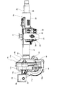
本発明の実施の形態の第1例について、図1~図6を用いて説明する。本例の電動パワーステアリング装置は、運転者の体格や運転姿勢に合わせて、ステアリングホイール1(図13参照)の上下位置および前後位置を調節可能とするチルト・テレスコピック機構、および、ステアリングホイール1の操作に要する力を軽減するための電動アシスト装置4bを備える。 First Example of Embodiment
A first example of an embodiment of the present invention will be described with reference to FIGS. The electric power steering apparatus according to the present embodiment includes a tilt / telescopic mechanism capable of adjusting the vertical position and the front / rear position of the steering wheel 1 (see FIG. 13) in accordance with the driver's physical constitution and driving posture; Anelectric assist device 4b is provided to reduce the force required for the operation.
本発明の実施の形態の第1例について、図1~図6を用いて説明する。本例の電動パワーステアリング装置は、運転者の体格や運転姿勢に合わせて、ステアリングホイール1(図13参照)の上下位置および前後位置を調節可能とするチルト・テレスコピック機構、および、ステアリングホイール1の操作に要する力を軽減するための電動アシスト装置4bを備える。 First Example of Embodiment
A first example of an embodiment of the present invention will be described with reference to FIGS. The electric power steering apparatus according to the present embodiment includes a tilt / telescopic mechanism capable of adjusting the vertical position and the front / rear position of the steering wheel 1 (see FIG. 13) in accordance with the driver's physical constitution and driving posture; An
ステアリングシャフト2aは、ステアリングコラム3aの内側に、図示しない複数の転がり軸受を介して、回転自在に支持される。ステアリングシャフト2aの後端部で、ステアリングコラム3aの後端開口よりも後方に突出した部分には、ステアリングホイール1が固定される。ステアリングシャフト2aは、スプライン係合などにより、回転力の伝達可能に、かつ、軸方向に関する相対変位を可能に組み合わされた、インナシャフト25およびアウタシャフト26を備える。インナシャフト25およびアウタシャフト26は、軸方向に相対変位して、ステアリングホイール1の前後位置の調節を可能にする機能、および、衝突事故の際にステアリングシャフト2aの全長を縮める機能を有する。
The steering shaft 2a is rotatably supported inside the steering column 3a via a plurality of rolling bearings (not shown). The steering wheel 1 is fixed to a portion of the rear end portion of the steering shaft 2a that protrudes rearward beyond the rear end opening of the steering column 3a. The steering shaft 2a includes an inner shaft 25 and an outer shaft 26, which can transmit a rotational force and allow relative displacement in the axial direction by spline engagement or the like. The inner shaft 25 and the outer shaft 26 are axially displaced relative to each other to adjust the longitudinal position of the steering wheel 1 and to reduce the overall length of the steering shaft 2a in the event of a collision.
ステアリングコラム3aは、全体として中空筒状で、インナコラム27およびアウタコラム28を備え、インナコラム27の後側部分に、アウタコラム28の前側部分が、軸方向に関する相対変位を可能に緩く嵌合する構造を有している。ステアリングコラム3aは、ステアリングホイール1の前後位置の調節を可能にする機能、および、衝突事故の際にステアリングシャフト2aとともにステアリングコラム3aの全長を縮める機能を有する。インナコラム27の前端部(図1の左端部)には、電動アシスト装置4bを構成するギヤハウジング14aが固定される。ギヤハウジング14aは、車体に固定されるロアブラケット29に対して、幅方向に配置されたチルト軸30を中心とする揺動を可能に支持される。なお、幅方向とは、電動パワーステアリング装置が組み付けられる車体の幅方向をいい、左右方向に相当する。
The steering column 3a has a hollow cylindrical shape as a whole, and includes an inner column 27 and an outer column 28. A front portion of the outer column 28 is fitted loosely to allow a relative displacement in the axial direction to a rear portion of the inner column 27 Have a structure that The steering column 3a has a function of enabling adjustment of the front-rear position of the steering wheel 1, and a function of shortening the total length of the steering column 3a together with the steering shaft 2a in the event of a collision. The gear housing 14a which comprises the electrically-driven assist apparatus 4b is fixed to the front end part (left end part of FIG. 1) of the inner column 27. As shown in FIG. The gear housing 14a is supported so as to be able to pivot about a tilt shaft 30 disposed in the width direction with respect to the lower bracket 29 fixed to the vehicle body. The width direction refers to the width direction of the vehicle body on which the electric power steering apparatus is assembled, and corresponds to the left-right direction.
アウタコラム28は、アッパブラケット31により車体に支持される。アッパブラケット31は、前方に向いた強い衝撃が加わった際に、車体から前方に離脱可能に構成される。アウタコラム28は、アッパブラケット31に対して、前後方向および上下方向に移動可能に支持されており、ステアリングホイール1の前後位置および上下位置を調節可能としている。このために、アウタコラム28を構成する1対の被挟持部32は、前後方向に長いテレスコ調節用長孔33を備える。また、1対の被挟持部32の幅方向両側に配置される、アッパブラケット31を構成する1対の支持板部34は、上下方向に長いチルト調節用長孔35を備える。テレスコ調節用長孔33およびチルト調節用長孔35に、調節ロッド36が幅方向に挿通される。調節ロッド36の端部に固定した図示しないレバーを操作し、調節ロッド36の周囲に配置した図示しない拡縮装置を幅方向に拡縮させることで、1対の支持板部34によって1対の被挟持部32を幅方向両側から挟持する力を調節可能としている。これにより、アウタコラム28をアッパブラケット31に対して固定したり、固定を解除したりすることが可能となっている。
The outer column 28 is supported by the upper bracket 31 on the vehicle body. The upper bracket 31 is configured to be detachable forward from the vehicle body when a strong impact directed to the front is applied. The outer column 28 is supported movably in the front and rear direction and in the up and down direction with respect to the upper bracket 31, and the front and rear position and the up and down position of the steering wheel 1 can be adjusted. For this purpose, the pair of held portions 32 constituting the outer column 28 are provided with telescopic adjustment long holes 33 which are long in the front-rear direction. Further, the pair of support plate portions 34 constituting the upper bracket 31 disposed on both sides in the width direction of the pair of held portions 32 are provided with long tilt adjustment long holes 35 in the vertical direction. The adjustment rod 36 is inserted in the width direction into the telescopic adjustment long hole 33 and the tilt adjustment long hole 35. By operating a lever (not shown) fixed to the end of the adjustment rod 36 and expanding / contracting the expansion / contraction device (not shown) arranged around the adjustment rod 36 in the width direction, a pair of support plates 34 hold a pair of clamped The force holding the portion 32 from both sides in the width direction can be adjusted. Thereby, the outer column 28 can be fixed to the upper bracket 31 or can be released from the fixing.
固定を解除した状態では、調節ロッド36がテレスコ調節用長孔33の内側で変位できる範囲で、アウタコラム28が前後移動して、ステアリングホイール1の前後位置が調節可能である。また、調節ロッド36がチルト調節用長孔35の内側で変位できる範囲で、ステアリングコラム3aが上下移動して、ステアリングホイール1の上下位置が調節可能である。この際、ステアリングコラム3aは、チルト軸30を中心に上下方向に揺動変位する。
When the fixation is released, the outer column 28 moves back and forth within the range in which the adjustment rod 36 can be displaced inside the telescopic adjustment long hole 33, and the longitudinal position of the steering wheel 1 can be adjusted. Further, the vertical position of the steering wheel 1 can be adjusted by vertically moving the steering column 3a within a range in which the adjusting rod 36 can be displaced inside the tilt adjusting long hole 35. At this time, the steering column 3 a swings in the vertical direction about the tilt shaft 30.
ステアリングホイール1の操作力を軽減するための電動アシスト装置4bは、ステアリングコラム3aの前方に配置されており、トルクセンサ10a、電動モータ11a、ウォーム減速機12a、出力軸13a、および、ギヤハウジング14aを備える。
An electric assist device 4b for reducing the operation force of the steering wheel 1 is disposed in front of the steering column 3a, and includes a torque sensor 10a, an electric motor 11a, a worm reduction gear 12a, an output shaft 13a, and a gear housing 14a. Equipped with
ウォーム減速機12aは、電動モータ11aにより回転駆動されるウォーム軸21aと、ウォーム軸21aの中間部に備えられたウォーム22aと、ウォーム22aと噛合するウォームホイール20aとを有する。
The worm reduction gear 12a has a worm shaft 21a rotationally driven by the electric motor 11a, a worm 22a provided at an intermediate portion of the worm shaft 21a, and a worm wheel 20a meshing with the worm 22a.
ギヤハウジング14aは、中間プレート37を介して前後方向に組み合わされた、前側ハウジング15aおよび後側ハウジング16aを備え、ウォーム減速機12aを内側に収容する。前側ハウジング15aおよび後側ハウジング16aはいずれも、鉄系合金もしくはアルミニウム合金などの軽合金の鋳造品(ダイキャスト成形品を含む)、または、合成樹脂の射出成形品である。
The gear housing 14a includes a front housing 15a and a rear housing 16a combined in the front-rear direction via an intermediate plate 37, and accommodates the worm reduction gear 12a inside. The front housing 15a and the rear housing 16a are both cast products (including die cast molded products) of light alloys such as iron-based alloys or aluminum alloys, or injection molded products of synthetic resin.
前側ハウジング15aは、内側にウォームホイール20aを収容するウォームホイール収容部17aと、内側にウォーム軸21aを収容するウォーム収容部18aと、複数(図示の例では3個)の補強リブ38a、38b、38cとを有する。
The front housing 15a includes a worm wheel receiving portion 17a receiving the worm wheel 20a inside, a worm receiving portion 18a receiving the worm shaft 21a inside, and a plurality of (three in the illustrated example) reinforcing ribs 38a and 38b, And 38c.
ウォームホイール収容部17aは、後方が開口したカップ形状および略水平方向に伸長する中心軸を有する。ウォームホイール収容部17aは、ウォームホイール20aの周囲に配置され、円筒状のウォームホイール用筒部39と、ウォームホイール20aの前方に配置され、かつ、ウォームホイール用筒部39の前端部から径方向内方に向けて略直角に折れ曲がった、円輪状のウォームホイール用底部40とを有する。
The worm wheel accommodating portion 17a has a cup shape opened at the rear and a central axis extending in a substantially horizontal direction. The worm wheel accommodating portion 17a is disposed around the worm wheel 20a, and is disposed forward of the worm wheel cylindrical portion 39 and the worm wheel 20a, and radially from the front end portion of the worm wheel cylindrical portion 39. And an annular worm wheel bottom 40 bent substantially at a right angle toward the inside.
ウォームホイール用底部40は、内周縁部に、略円筒状の内径側筒部41を備える。ウォームホイール用底部40は、径方向中央部である、内径側筒部41の径方向内側部分に、軸受保持孔42を備える。また、ウォームホイール用底部40は、軸受保持孔42の前方側の開口縁部に、ウォームホイール用底部40の径方向中間部および外側部よりも前方に突出した環状突部43を備える。環状突部43は、内径側筒部41の前端部により構成される。
The worm wheel bottom portion 40 is provided with a substantially cylindrical inner diameter side cylindrical portion 41 at an inner peripheral edge portion. The bottom portion 40 for the worm wheel is provided with a bearing holding hole 42 at a radially inner portion of the inner diameter side cylindrical portion 41 which is a radially central portion. Further, the worm wheel bottom portion 40 is provided with an annular projection 43 at the opening edge portion on the front side of the bearing holding hole 42, which protrudes forward more than the radial direction intermediate portion and the outer portion of the worm wheel bottom portion 40. The annular projection 43 is constituted by the front end portion of the inner diameter side cylindrical portion 41.
ウォーム収容部18aは、略有底円筒形状を有する。ウォーム収容部18aは、ウォームホイール収容部17aの外径側部分の周方向一部で、電動パワーステアリング装置の組付状態で下方に位置する部分に配置される。ウォーム収容部18aの内部空間は、ウォームホイール収容部17aの内部空間に連通する。ウォーム収容部18aは、略水平方向に伸長するが、ウォームホイール収容部17aの中心軸とは捩れの位置関係にある中心軸を有する。ウォーム収容部18aは、開口側端部に、径方向外方に張り出したモータ取付フランジ44を備える。
The worm accommodating portion 18a has a substantially bottomed cylindrical shape. The worm accommodating portion 18a is a part of the outer diameter side of the worm wheel accommodating portion 17a in the circumferential direction, and is disposed at a portion located below in the assembled state of the electric power steering apparatus. The internal space of the worm accommodating portion 18a communicates with the internal space of the worm wheel accommodating portion 17a. The worm accommodating portion 18a extends in a substantially horizontal direction, but has a central axis which is in a twisted positional relationship with the central axis of the worm wheel accommodating portion 17a. The worm accommodating portion 18 a includes a motor mounting flange 44 protruding radially outward at an opening side end.
本例のギヤハウジング14aは、ウォームホイール用底部40の前側面の上下方向中間部から前方に突出し、ギヤハウジング14aをロアブラケット29を介して車体に揺動変位を可能に支持するための1対の取付ステー19aを備える。具体的には、1対の取付ステー19aは、前側ハウジング15aのウォームホイール用底部40のうちの、車体の幅方向に関して軸受保持孔42を両側から挟む位置に、互いに離隔した状態で配置される。1対の取付ステー19aは、先端部に、幅方向に貫通する、チルト軸30を挿通するための取付孔45をそれぞれ備える。取付ステー19aの先半部は、先端側に向かうほど上下方向に関する寸法が小さくなる先細形状を有するのに対し、取付ステー19aの基半部は、上下方向に関する寸法は変わらずに、幅方向に関する寸法が基端側に向かうほど増大する(幅方向に関して内側に張り出す)形状を有する。また、取付ステー19aの基端部の幅方向外側面は、ウォームホイール用筒部39の外周面に連続するのに対し、取付ステー19aの基端部の幅方向内側面は、環状突部43に連続する。また、幅方向に関してウォーム収容部18aの開口側(図2および図5の左側)に位置する取付ステー19aの幅方向外側面の下端部は、モータ取付フランジ44の幅方向内側面の上端部に連続する。1対の取付ステー19aは、ロアブラケット29を構成する1対の側板部46の間に配置される。
The gear housing 14a of this embodiment protrudes forward from the vertical middle portion of the front side surface of the bottom portion 40 for the worm wheel, and is a pair for supporting the gear housing 14a to be able to perform swing displacement on the vehicle body via the lower bracket 29. The mounting stay 19a is provided. Specifically, the pair of mounting stays 19a are arranged at positions mutually sandwiching the bearing holding holes 42 in the width direction of the vehicle body in the worm wheel bottom portion 40 of the front housing 15a, being mutually separated. . Each of the pair of mounting stays 19a has mounting holes 45 at its tip end, which pass through in the width direction and into which the tilt shaft 30 is inserted. The front half portion of the mounting stay 19a has a tapered shape in which the dimension in the vertical direction decreases toward the tip end, whereas the base half portion of the mounting stay 19a does not change in the dimension in the vertical direction. It has a shape that increases in size toward the proximal side (projects inward in the width direction). The widthwise outer surface of the base end portion of the mounting stay 19a is continuous with the outer peripheral surface of the worm wheel cylindrical portion 39, while the widthwise inner surface of the base end portion of the mounting stay 19a is annular projection 43 To be continuous. Further, the lower end portion of the widthwise outer surface of the mounting stay 19a positioned on the opening side (left side in FIGS. 2 and 5) of the worm accommodating portion 18a in the width direction is the upper end portion of the inner surface of the motor mounting flange 44 in the width direction. Be continuous. The pair of mounting stays 19 a is disposed between the pair of side plate portions 46 that constitute the lower bracket 29.
3本の補強リブ38a、38b、38cは、それぞれ中実状で、周囲に存在する部分よりも大きな前後方向に関する厚さ寸法を有し、前側ハウジング15aの前側面に、ウォーム収容部18aとウォームホイール用底部40とに架けわたされるように配置される。具体的には、前側ハウジング15aのうち、補強リブ38a、38b、38cを設置した部分における厚さ寸法は、前側ハウジング15aのうち、補強リブ38a、38b、38cの周囲に存在する部分における厚さ寸法のたとえば10倍以下となる範囲で、十分に大きく設定される。ただし、前側ハウジング15aのうち、補強リブ38a、38b、38cを設置した部分における厚さ寸法は、補強リブ38a、38b、38cが環状突部43から軸方向に突出しないように設定されることが好ましい。
Each of the three reinforcing ribs 38a, 38b and 38c is solid, has a thickness dimension in the front-rear direction larger than a portion present in the periphery, and on the front side surface of the front housing 15a, the worm accommodating portion 18a and the worm wheel It is arranged to be bridged with the bottom 40. Specifically, the thickness dimension of the portion of the front housing 15a where the reinforcing ribs 38a, 38b and 38c are installed is the thickness of the portion of the front housing 15a which exists around the reinforcing ribs 38a, 38b and 38c. It is set sufficiently large within a range of, for example, 10 times or less of the dimension. However, in the front housing 15a, the thickness dimension of the portion where the reinforcing ribs 38a, 38b, 38c are installed is set such that the reinforcing ribs 38a, 38b, 38c do not project axially from the annular projection 43 preferable.
本例では、補強リブ38a、38b、38cは、ウォームホイール収容部17aとウォーム収容部18aとの配列方向に一致する、ウォームホイール20aとウォーム軸21aに備えられたウォーム22aとの噛み合い反力の作用方向(図2および図4の上下方向)に伸長する。すなわち、補強リブ38a、38b、38cは、ウォームホイール20aの中心軸O20と電動モータ11aの中心軸O11aとに直交する仮想直線Lに対して実質的に平行に配置される。なお、実質的に平行とは、電動パワーステアリング装置の製造誤差や組立誤差に起因して、補強リブ38a、38b、38cの形成方向が仮想直線Lに対し傾斜する場合を含む。なお、後述するように、ウォームホイール20aとウォーム22aとの噛み合い反力に対する前側ハウジング15aの剛性を向上させられる限りにおいて、補強リブ38a、38b、38cの伸長方向を仮想直線Lに対して傾斜させることもできる。具体的には、補強リブ38a、38b、38cの伸長方向と仮想直線Lとがなす角度は、45度以下の任意の角度に設定可能であり、0度、すなわち、補強リブ38a、38b、38cの形成方向と仮想直線Lと平行にすることが好ましい。また、補強リブ38aの伸長方向と仮想直線Lとがなす角度を0度として、補強リブ38b、38cの伸長方向と仮想直線Ltoがなす角度を、45度以下の任意の角度とすることもできる。
In this example, the reinforcing ribs 38a, 38b, and 38c are in the alignment direction of the worm wheel accommodating portion 17a and the worm accommodating portion 18a, and are the engagement reaction force between the worm wheel 20a and the worm 22a provided on the worm shaft 21a. It extends in the direction of action (vertical direction in FIGS. 2 and 4). In other words, the reinforcing ribs 38a, 38b, 38c are substantially parallel to the imaginary straight line L that is perpendicular to the central axis O 11a of the central axis O 20 and the electric motor 11a of the worm wheel 20a. The term "substantially parallel" includes the case where the forming direction of the reinforcing ribs 38a, 38b and 38c is inclined with respect to the imaginary straight line L due to a manufacturing error or an assembly error of the electric power steering apparatus. As will be described later, the extending direction of the reinforcing ribs 38a, 38b and 38c is inclined with respect to the imaginary straight line L as long as the rigidity of the front housing 15a against the engagement reaction force between the worm wheel 20a and the worm 22a can be improved. It can also be done. Specifically, the angle between the extension direction of the reinforcing ribs 38a, 38b, 38c and the imaginary straight line L can be set to any angle of 45 degrees or less, that is, 0 degrees, that is, the reinforcing ribs 38a, 38b, 38c. It is preferable to make it parallel to the formation direction of and the imaginary straight line L. Further, the angle between the extension direction of the reinforcing ribs 38b and 38c and the virtual straight line Lto can be an arbitrary angle of 45 degrees or less, where the angle between the extension direction of the reinforcing rib 38a and the virtual straight line L is 0 degrees. .
噛み合い反力とは、ウォームホイール20aとウォーム軸21とが離れるように互いに反対向きに作用する力をいう。本例では、補強リブ38a、38b、38cを、噛み合い反力の作用方向に伸長させているため、噛み合い反力に対する前側ハウジング15aの剛性を効果的に向上させることができる。このため、前側ハウジング15aを薄肉化した場合にも、前側ハウジング15aに、噛み合い反力に起因して有害な変形などが生じることが防止される。
The meshing reaction force is a force acting in the opposite direction so that the worm wheel 20a and the worm shaft 21 are separated. In this example, since the reinforcing ribs 38a, 38b and 38c are extended in the acting direction of the meshing reaction force, the rigidity of the front housing 15a with respect to the meshing reaction force can be effectively improved. For this reason, even when the front housing 15a is thinned, it is possible to prevent the occurrence of harmful deformation or the like due to the meshing reaction force in the front housing 15a.
補強リブ38a、38b、38cは、台形状または凸円弧形状など、前方に向かうほど幅方向(短手方向)に関する寸法が小さくなる断面形状を有する。補強リブ38a、38b、38cの幅方向側面のそれぞれに抜き勾配を持たせることにより、鋳造型または射出成形型からの離型性が確保される。また、補強リブ38a、38b、38cの前側面は、環状突部43の前側面と同じ位置、あるいは、環状突部43の前側面よりも後方に配置される。これにより、補強リブ38a、38b、38cに起因して、前側ハウジング15aの前方に配置する他の部材のレイアウト性が悪くなることが防止される。
The reinforcing ribs 38a, 38b, and 38c have a cross-sectional shape such as a trapezoidal shape or a convex arc shape, in which the dimension in the width direction (short direction) decreases toward the front. By making each of the widthwise side surfaces of the reinforcing ribs 38a, 38b, 38c have a draft, releasability from the casting mold or the injection mold is secured. Further, the front side surfaces of the reinforcing ribs 38 a, 38 b and 38 c are disposed at the same position as the front side surface of the annular projection 43 or at the rear of the front side surface of the annular projection 43. This prevents the deterioration of the layout of the other members disposed in front of the front housing 15a due to the reinforcing ribs 38a, 38b and 38c.
補強リブ38a、38b、38cのうち、幅方向中間部に設置された補強リブ38aは、環状突部43のうちでウォーム収容部18aに最も近接した下端部と、ウォーム収容部18aの軸方向中間部とに架けわたされるように配置される。このため、補強リブ38aの上端部は、環状突部43の下端部に連結する。これに対し、幅方向両側に設置された2本の補強リブ38b、38cは、1対の取付ステー19aの基端部の下面と、ウォーム収容部18aの軸方向両側部とに架けわたされるように配置される。このため、補強リブ38b、38cのそれぞれの上端部は、取付ステー19aの基端部の下面に連結する。すなわち、補強リブ38b、38cと1対の取付ステー19aとは、それぞれ上下方向に連続するように配置される。
Of the reinforcing ribs 38a, 38b, 38c, the reinforcing rib 38a installed at the widthwise intermediate portion is the lower end portion of the annular projection 43 closest to the worm accommodating portion 18a, and the axial intermediate intermediate portion of the worm accommodating portion 18a. It is arranged to be bridged with the department. Therefore, the upper end of the reinforcing rib 38 a is connected to the lower end of the annular projection 43. On the other hand, the two reinforcing ribs 38b and 38c installed on both sides in the width direction are bridged by the lower surface of the base end of the pair of mounting stays 19a and the two axial sides of the worm accommodating portion 18a. Will be placed. Therefore, the upper ends of the reinforcing ribs 38b and 38c are connected to the lower surface of the base end of the mounting stay 19a. That is, the reinforcing ribs 38b and 38c and the pair of mounting stays 19a are arranged to be continuous in the vertical direction.
補強リブ38aの幅方向に関する厚さ寸法(短手方向に関する厚さ寸法)は、全長にわたりほぼ一定であるのに対し、補強リブ38b、38cの幅方向に関する厚さ寸法は、取付ステー19aに近づくほど大きくなっている。
The thickness dimension of the reinforcing rib 38a in the width direction (thickness dimension in the lateral direction) is substantially constant over the entire length, while the thickness dimension in the width direction of the reinforcing ribs 38b and 38c approaches the mounting stay 19a. It is getting bigger.
本例では、前側ハウジング15aは、前側面の複数箇所に、周囲に存在する部分よりも前方に突出した複数(図示の例では3個)のボス部47を備える。具体的には、ウォームホイール用底部40の前側面の上端部中央部、および、ウォームホイール収容部17aの外周縁部のうちウォーム収容部18aとの連続部である2個所位置に、それぞれが円筒状のボス部47が配置される。ボス部47は、周囲に存在する部分よりも、前方に突出しており、これにより厚肉になっている。なお、ウォームホイール収容部17aの外周縁部に配置された2つのボス部47は、それぞれ補強リブ38b、38cと連続する。ボス部47は、ギヤハウジング14aを、ウォーム減速機12aの周囲に組み付ける際に、ボス部47を組立装置や治具により把持するなどして、ギヤハウジング14aを組み立てる作業の効率を向上させる機能を有する。
In the present embodiment, the front housing 15a is provided with a plurality of (three in the illustrated example) bosses 47 projecting forward relative to a portion present in the periphery at a plurality of locations on the front side. Specifically, at the center of the upper end portion of the front side of the bottom portion 40 for the worm wheel, and at the outer peripheral edge portion of the worm wheel accommodating portion 17a at two positions which are continuous portions with the worm accommodating portion 18a, respectively The bosses 47 are arranged. The bosses 47 project more forward than the portions present around them, and are thus thicker. The two bosses 47 arranged at the outer peripheral edge of the worm wheel housing 17a are continuous with the reinforcing ribs 38b and 38c, respectively. When assembling the gear housing 14a around the worm reduction gear 12a, the boss portion 47 has a function of improving the efficiency of the work of assembling the gear housing 14a by gripping the boss portion 47 with an assembly device or jig or the like. Have.
本例では、上述のような構成を有する前側ハウジング15aを、キャビティ61を有する金型(鋳造型、射出成形型)60を用いて、鋳造または射出成形により作製する際に、図6に示すように、材料(溶湯、合成樹脂)の供給口となる金型60のゲートGを、前側ハウジング15aを形成するためのキャビティ61のうち、ウォーム収容部18aを形成するためのウォーム収容部形成空間62を挟んで、ウォームホイール収容部17aを形成するためのウォームホイール収容部形成空間63の反対側に配置する。すなわち、ゲートGを、ウォーム収容部形成空間62が上流側となるように配置する。これにより、ウォーム収容部形成空間62を通過した材料が、ウォームホイール収容部形成空間63側に流動する。このため、本例の前側ハウジング15aでは、ウォーム収容部18aが、材料の流れ方向に関してウォームホイール収容部17aよりも上流側に位置する。
In this example, as shown in FIG. 6, the front housing 15a having the above-described configuration is produced by casting or injection molding using a mold (casting mold, injection molding mold) 60 having a cavity 61. In the cavity 61 for forming the front housing 15a, the gate G for the mold 60 serving as a supply port for the material (molten metal, synthetic resin), a worm accommodation portion forming space 62 for forming the worm accommodation portion 18a. , And is disposed on the opposite side of the worm wheel accommodating portion forming space 63 for forming the worm wheel accommodating portion 17a. That is, the gate G is disposed such that the worm accommodating portion forming space 62 is on the upstream side. Thus, the material that has passed through the worm accommodating portion forming space 62 flows to the worm wheel accommodating portion forming space 63 side. For this reason, in the front side housing 15a of this example, the worm accommodating portion 18a is positioned upstream of the worm wheel accommodating portion 17a in the material flow direction.
これに対し、後側ハウジング16aは、全体として中空筒状を有する、鋳造品または合成樹脂の射出成形品からなり、固定筒部48と、大径筒部49と、連続部50とを備える。固定筒部48は、円筒状で、インナコラム27の前端部に内嵌固定される。大径筒部49は、トルクセンサ10aの周囲に配置され、中間プレート37を介して前側ハウジング15aの後端開口部に突き合わされる。連続部50は、固定筒部48の前端部と大径筒部49の後端部とを接続する。
On the other hand, the rear housing 16 a is formed of a cast or a synthetic resin injection-molded article having a hollow cylindrical shape as a whole, and includes a fixed cylindrical portion 48, a large diameter cylindrical portion 49 and a continuous portion 50. The fixed cylindrical portion 48 has a cylindrical shape and is fixedly fitted to the front end portion of the inner column 27. The large diameter cylindrical portion 49 is disposed around the torque sensor 10 a and abuts on the rear end opening of the front housing 15 a via the intermediate plate 37. The continuous portion 50 connects the front end portion of the fixed cylindrical portion 48 and the rear end portion of the large diameter cylindrical portion 49.
本例では、前側ハウジング15aおよび後側ハウジング16aは、中間プレート37を介して組み合わされた状態で、複数本(図示の例では3本)のボルト57により互いに連結される。具体的には、全体が略円輪状に構成された中間プレート37のうち、前側面の外径側部分に備えられた前側嵌合部51に対して、前側ハウジング15a(ウォームホイール用筒部39)の後端部が外嵌し、かつ、後側面の外径側部分に備えられた後側嵌合部52に対し、後側ハウジング16(大径筒部49)の前端部が外嵌する。この状態で、前側ハウジング15aを構成するウォームホイール用筒部39の外周面に形成された複数(図示の例では3つ)の前側結合フランジ53と、後側ハウジング16aの大径筒部49の外周面に形成された複数(図示の例では3つ)後側結合フランジ58とが、それぞれボルト57により互いに結合される。
In the present embodiment, the front housing 15a and the rear housing 16a are connected to each other by a plurality of (three in the illustrated example) bolts 57 in a state where they are combined via the intermediate plate 37. Specifically, with respect to the front fitting portion 51 provided on the outer diameter side portion of the front side surface of the intermediate plate 37 which is generally formed in a substantially annular shape, the front housing 15a (cylindrical portion 39 for worm wheel And the front end portion of the rear housing 16 (large diameter cylindrical portion 49) is externally fitted to the rear fitting portion 52 provided on the outer diameter side portion of the rear side. . In this state, a plurality of (three in the illustrated example) front coupling flanges 53 formed on the outer peripheral surface of the worm wheel cylindrical portion 39 constituting the front housing 15a and the large diameter cylindrical portion 49 of the rear housing 16a A plurality of (three in the illustrated example) rear coupling flanges 58 formed on the outer peripheral surface are coupled to one another by bolts 57, respectively.
本例では、上述のような構成を有するギヤハウジング14aの内側に、出力軸13aが、1対の転がり軸受54a、54bにより回転自在に支持される。1対の転がり軸受54a、54bのうち、前側の転がり軸受54aは、前側ハウジング15aを構成する軸受保持孔42に内嵌保持され、後側の転がり軸受54bは、中間プレート37の内周面に内嵌保持される。また、前側の転がり軸受54aを構成する外輪は、軸受保持孔42の内周面の軸方向中間部に圧入により内嵌固定される。さらに、前側の転がり軸受54aを構成する外輪は、軸受保持孔42の前端寄り部分に備えられ、後方を向いた段差面と、軸受保持孔42の内周面の後端寄り部分に形成された係止溝に係止された止め輪とにより、両側から挟持される。出力軸13aは、ステアリングシャフト2aを構成するインナシャフト25の前端部に対し、トーションバー24aを介して連結される。また、出力軸13aの前端部で、ギヤハウジング14aの外部に突出した部分には、自在継手5a(図13参照)が結合される。
In this example, the output shaft 13a is rotatably supported by the pair of rolling bearings 54a and 54b inside the gear housing 14a having the above-described configuration. Of the pair of rolling bearings 54a and 54b, the rolling bearing 54a on the front side is internally fitted and held in the bearing holding hole 42 constituting the front housing 15a, and the rolling bearing 54b on the rear side is on the inner circumferential surface of the intermediate plate 37. Internally held. Further, the outer ring forming the front side rolling bearing 54 a is fitted and fixed to the axially intermediate portion of the inner peripheral surface of the bearing holding hole 42 by press-fitting. Furthermore, the outer ring constituting the rolling bearing 54 a on the front side is provided at a portion near the front end of the bearing holding hole 42 and is formed at a step surface facing rearward and a portion near the rear end of the inner circumferential surface of the bearing holding hole 42 It is clamped from both sides by the snap ring locked by the locking groove. The output shaft 13a is coupled to the front end portion of the inner shaft 25 constituting the steering shaft 2a via a torsion bar 24a. Further, a universal joint 5a (see FIG. 13) is coupled to a portion of the front end portion of the output shaft 13a that protrudes to the outside of the gear housing 14a.
出力軸13aの中間部で、1対の転がり軸受54a、54bの間には、ウォーム減速機12aを構成するウォームホイール20aが外嵌固定される。この状態で、ウォームホイール20aは、前側ハウジング15aを構成するウォームホイール収容部17aの内側に配置される。
At an intermediate portion of the output shaft 13a, a worm wheel 20a constituting the worm reduction gear 12a is externally fitted and fixed between the pair of rolling bearings 54a and 54b. In this state, the worm wheel 20a is disposed inside the worm wheel receiving portion 17a that constitutes the front housing 15a.
ウォーム減速機12aを構成するウォーム軸21aは、ウォーム収容部18aの内側に、1対の転がり軸受55a、55bを介して回転自在に支持される。この状態で、ウォーム軸21aの中間部に備えられたウォーム22aは、ウォームホイール20aと噛合する。ウォーム軸21aの基端部には、電動モータ11aの出力軸が連結される。これにより、電動モータ11aの補助動力を、ウォームホイール20aに伝達可能としている。電動モータ11aは、前側ハウジング15aを構成するモータ取付フランジ44を介して、ギヤハウジング14aに支持固定される。なお、本例では、ウォーム軸21aの先端部に外嵌された転がり軸受55aと、ウォーム収容部18aの内周面との間に、ウォーム軸21aの先端部を、ウォームホイール20a側に向けて弾性的に付勢する予圧付与機構64を設けることにより、ウォームホイール20aとウォーム22aとの噛合部に存在するバックラッシュを抑えている。
The worm shaft 21a constituting the worm reduction gear 12a is rotatably supported inside the worm accommodating portion 18a via a pair of rolling bearings 55a and 55b. In this state, the worm 22a provided at the middle portion of the worm shaft 21a meshes with the worm wheel 20a. The output shaft of the electric motor 11a is connected to the proximal end of the worm shaft 21a. Thereby, the auxiliary power of the electric motor 11a can be transmitted to the worm wheel 20a. The electric motor 11a is supported and fixed to the gear housing 14a via a motor mounting flange 44 that constitutes the front housing 15a. In this example, the tip end of the worm shaft 21a is directed to the worm wheel 20a side between the rolling bearing 55a externally fitted to the tip end of the worm shaft 21a and the inner peripheral surface of the worm accommodating portion 18a. By providing the elastically biasing preloading mechanism 64, the backlash present in the meshing portion between the worm wheel 20a and the worm 22a is suppressed.
後側ハウジング16aを構成する大径筒部49の内側で、インナシャフト25の前端部の周囲に、トルクセンサ10aが配置される。電動モータ11aは、トルクセンサ10aが検出する、ステアリングホイール1からステアリングシャフト2aに加えられる操舵トルクの方向および大きさに応じて、ウォーム軸21aを回転駆動し、出力軸13aに補助動力(補助トルク)を付与する。この結果、左右1対の操舵輪に舵角を付与する際に必要になる、ステアリングホイール1の操作力が軽減される。
A torque sensor 10a is disposed around the front end of the inner shaft 25 inside the large diameter cylindrical portion 49 that constitutes the rear housing 16a. The electric motor 11a rotationally drives the worm shaft 21a according to the direction and the magnitude of the steering torque applied from the steering wheel 1 to the steering shaft 2a detected by the torque sensor 10a, and the auxiliary power (assist torque Give). As a result, the operation force of the steering wheel 1, which is necessary when giving the steering angle to the pair of left and right steered wheels, is reduced.
以上のような構成を有する本例の電動パワーステアリング装置によれば、ギヤハウジング14aを構成する前側ハウジング15aに関して、薄肉化を図る場合にも、剛性を確保できるとともに、製造時の成形性を確保できる。すなわち、本例では、前側ハウジング15aの前側面に、補強リブ38a、38b、38cを、ウォーム収容部18aとウォームホイール用底部40との間に架けわたすように配置し、かつ、補強リブ38a、38b、38cの伸長方向を、ウォームホイール20aとウォーム22aとの噛み合い反力の作用方向に一致させている。このため、噛み合い反力に対する前側ハウジング15aの剛性を効果的に向上させることができる。したがって、前側ハウジング15aを薄肉化した場合にも、前側ハウジング15aに、噛み合い反力に起因して有害な変形などが発生してしまうことが防止される。
According to the electric power steering apparatus of this example having the above-described configuration, rigidity can be secured even when thinning the front housing 15a constituting the gear housing 14a, and formability at the time of manufacture is secured. it can. That is, in the present embodiment, reinforcing ribs 38a, 38b, 38c are arranged on the front side of the front housing 15a so as to bridge between the worm accommodating portion 18a and the worm wheel bottom 40 and the reinforcing ribs 38a, The extending directions of 38b and 38c are made to coincide with the acting direction of the meshing reaction force between the worm wheel 20a and the worm 22a. Therefore, the rigidity of the front housing 15a against the engagement reaction force can be effectively improved. Therefore, even when the front housing 15a is thinned, the occurrence of harmful deformation or the like due to the meshing reaction force is prevented in the front housing 15a.
本例では、前側ハウジング15aに補強リブ38a、38b、38cを形成するため、前側ハウジング15aを鋳造または射出成形により作製する際に用いる金型60のキャビティ61に関して、補強リブ38a、38b、38cを形成するための空間分だけ、材料が流れる空間の断面積を大きくすることができる。さらに、補強リブ38a、38b、38cの伸長方向を、ウォームホイール収容部17aとウォーム収容部18aとの配列方向に向いた、前記噛み合い反力の作用方向に一致させているため、図6に材料の流れを矢印で示したように、ゲートGから供給した材料を、キャビティ61のうちで補強リブ38a、38b、38cを形成するための空間を通じて、ウォームホイール収容部形成空間63に効率よく供給することができる。このように、本例の構造によれば、材料の流動性(湯流れ性)を良好にすることができ、製造時における成形性を向上させることができる。
In this example, in order to form the reinforcing ribs 38a, 38b and 38c in the front side housing 15a, the reinforcing ribs 38a, 38b and 38c are made with respect to the cavity 61 of the mold 60 used when producing the front side housing 15a by casting or injection molding. The cross-sectional area of the space through which the material flows can be increased by the space for forming. Furthermore, since the extending direction of the reinforcing ribs 38a, 38b, 38c is the same as the acting direction of the meshing reaction force directed in the arrangement direction of the worm wheel accommodating portion 17a and the worm accommodating portion 18a, the material shown in FIG. The material supplied from the gate G is efficiently supplied to the worm wheel container forming space 63 through the space for forming the reinforcing ribs 38a, 38b and 38c in the cavity 61, as indicated by the arrows in FIG. be able to. As described above, according to the structure of this example, the flowability (flowability of the material) of the material can be improved, and the formability at the time of manufacture can be improved.
しかも、2本の補強リブ38b、38cをそれぞれ取付ステー19aに連続するように形成するため、補強リブ38b、38cを形成するための空間を通じて、取付ステー19aを形成するための空間に、材料を直接供給することができる。このため、取付ステー19aを形成するための空間に材料を十分に供給することができ、取付ステー19aの強度および剛性を向上させることができる。また、補強リブ38aを形成するための空間を通じて、内径側筒部41を形成するための空間、特にこの空間のうち環状突部43を形成するための部分に、材料を直接供給することもできる。したがって、本例によれば、前側ハウジング15aの品質の低下が防止される。すなわち、不良品の発生が低減される。また、前側ハウジング15aの実体強度を向上させることもできる。さらに、以上のように、剛性を確保できるとともに、製造時の成形性を確保できるため、薄肉化による軽量化を図ることができる。
Moreover, in order to form the two reinforcing ribs 38b and 38c so as to be continuous with the mounting stay 19a, a material is formed in the space for forming the mounting stay 19a through the space for forming the reinforcing ribs 38b and 38c. It can be supplied directly. Therefore, the material can be sufficiently supplied to the space for forming the mounting stay 19a, and the strength and rigidity of the mounting stay 19a can be improved. Also, the material can be directly supplied to the space for forming the inner diameter side cylindrical portion 41, particularly to the portion for forming the annular projection 43 in the space, through the space for forming the reinforcing rib 38a. . Therefore, according to this embodiment, the deterioration of the quality of the front housing 15a is prevented. That is, the occurrence of defective products is reduced. Also, the substantial strength of the front housing 15a can be improved. Furthermore, as described above, the rigidity can be secured, and the formability at the time of manufacture can be secured, so weight reduction by thinning can be achieved.
また、補強リブ38a、38b、38cを備えることにより、前側ハウジング15aの剛性および取付ステー19aの剛性を向上させることができる。このため、電動パワーステアリング装置の作動フィーリングや作動効率を向上させることができ、かつ、振動や異音の発生を抑制することができる。また、取付ステー19aの剛性を向上できるため、ステアリングシャフト2aおよびステアリングコラム3aの収縮動作の挙動を安定させることができ、衝突エネルギの吸収特性を良好にすることもできる。なお、本例では、前側ハウジング15aは、3個の補強リブ38a、38b、38cを備えるが、1個の補強リブのみを備えた場合でも、上記の本発明の作用および効果は奏される。補強リブの個数、設置位置、および形状は、前側ハウジングを構成する各部の配置および形状、および、その作製時における材料の流動、並びに、前側ハウジングの剛性の確保の観点から、任意かつ適切に選択される。
Further, by providing the reinforcing ribs 38a, 38b, 38c, the rigidity of the front housing 15a and the rigidity of the mounting stay 19a can be improved. Therefore, the operation feeling and operation efficiency of the electric power steering apparatus can be improved, and the generation of vibration and noise can be suppressed. Further, since the rigidity of the mounting stay 19a can be improved, the behavior of the contraction operation of the steering shaft 2a and the steering column 3a can be stabilized, and the absorption characteristic of collision energy can also be improved. In the present embodiment, the front housing 15a includes the three reinforcing ribs 38a, 38b, and 38c. However, even when only one reinforcing rib is provided, the above-described operation and effects of the present invention can be achieved. The number, installation position, and shape of the reinforcing ribs are arbitrarily and appropriately selected from the viewpoint of securing the rigidity of the front housing and the arrangement and shape of the parts constituting the front housing, the flow of materials at the time of production thereof, and the rigidity of the front housing. Be done.
[実施の形態の第2例]
実施の形態の第2例について、図7~図12を用いて説明する。本例では、前側ハウジング15bの構造を、実施の形態の第1例の構造から変更している。本例の前側ハウジング15bでは、ウォーム収容部18bは、ウォームホイール収容部17aの外径側部分の周方向一部で、電動パワーステアリング装置の組付状態で、車体の幅方向に関して出力軸13aの側方に位置する部分に配置される。このため、ウォーム収容部18bの中心軸は、上下方向に向いている。また、ウォーム収容部18bの開口部は、電動パワーステアリング装置の組付状態で上方を向いている。さらに、ウォームホイール用底部40は、前側面の上端部に、実施の形態の第1例で示した1対の取付ステー19aを幅方向に連続させた形状を有する、1つの取付ステー19bを備える。本例では、取付ステー19bの幅方向外側面は、ウォーム収容部18bの開口側端部に備えられたモータ取付フランジ44の幅方向側面に連続する。また、モータ取付フランジ44は、電動モータ11a、および、基板を内蔵した制御装置59を支持する。 Second Example of Embodiment
A second example of the embodiment will be described using FIG. 7 to FIG. In this example, the structure of thefront housing 15b is changed from the structure of the first example of the embodiment. In the front housing 15b of this example, the worm accommodating portion 18b is a part of the outer diameter side of the worm wheel accommodating portion 17a in the circumferential direction, and in the assembled state of the electric power steering apparatus, the output shaft 13a It is arranged in a laterally located part. For this reason, the central axis of the worm accommodating portion 18b is directed in the vertical direction. Further, the opening of the worm accommodating portion 18b is directed upward in the assembled state of the electric power steering apparatus. Furthermore, the bottom portion 40 for the worm wheel is provided with one mounting stay 19b having a shape in which the pair of mounting stays 19a shown in the first example of the embodiment are continued in the width direction at the upper end portion of the front side surface. . In this example, the widthwise outer side surface of the mounting stay 19b is continuous with the widthwise side surface of the motor mounting flange 44 provided at the open end of the worm housing 18b. In addition, the motor mounting flange 44 supports the electric motor 11 a and the control device 59 which incorporates a substrate.
実施の形態の第2例について、図7~図12を用いて説明する。本例では、前側ハウジング15bの構造を、実施の形態の第1例の構造から変更している。本例の前側ハウジング15bでは、ウォーム収容部18bは、ウォームホイール収容部17aの外径側部分の周方向一部で、電動パワーステアリング装置の組付状態で、車体の幅方向に関して出力軸13aの側方に位置する部分に配置される。このため、ウォーム収容部18bの中心軸は、上下方向に向いている。また、ウォーム収容部18bの開口部は、電動パワーステアリング装置の組付状態で上方を向いている。さらに、ウォームホイール用底部40は、前側面の上端部に、実施の形態の第1例で示した1対の取付ステー19aを幅方向に連続させた形状を有する、1つの取付ステー19bを備える。本例では、取付ステー19bの幅方向外側面は、ウォーム収容部18bの開口側端部に備えられたモータ取付フランジ44の幅方向側面に連続する。また、モータ取付フランジ44は、電動モータ11a、および、基板を内蔵した制御装置59を支持する。 Second Example of Embodiment
A second example of the embodiment will be described using FIG. 7 to FIG. In this example, the structure of the
本例では、ウォーム収容部18bの配置を変更したこと、および、取付ステー19bの形状を変更したことに対応して、ウォームホイール用底部40は、前側面に、2本の補強リブ38a、38dだけを備える。具体的には、環状突部43のうちでウォーム収容部18bに最も近接した端部とウォーム収容部18bの上下方向中間部とに架けわたすように、補強リブ38aが配置され、かつ、取付ステー19bの基端部の幅方向外側面とウォーム収容部18bの上端寄り部分とに架けわたすように、補強リブ38dが配置される。本例では、ウォーム収容部18bの下端寄り部分と対応する部分には、取付ステーが配置されていないため、上述のように2本の補強リブ38a、38dのみが備えられる。補強リブ38a、38dは、ウォームホイール20aとウォーム22aとの噛み合い反力の作用方向に伸長する。
In this example, the bottom portion 40 for the worm wheel has two reinforcing ribs 38a, 38d on the front side surface, corresponding to the change in the arrangement of the worm accommodating portion 18b and the change in the shape of the mounting stay 19b. Just have. Specifically, the reinforcing rib 38a is disposed so as to bridge the end of the annular projection 43 closest to the worm accommodating portion 18b and the vertically intermediate portion of the worm accommodating portion 18b, and the mounting stay A reinforcing rib 38d is disposed so as to bridge the widthwise outer surface of the proximal end portion 19b and a portion near the upper end of the worm accommodating portion 18b. In the present embodiment, the mounting stay is not disposed at a portion corresponding to the portion closer to the lower end of the worm accommodating portion 18b, so only two reinforcing ribs 38a and 38d are provided as described above. The reinforcing ribs 38a and 38d extend in the acting direction of the meshing reaction force between the worm wheel 20a and the worm 22a.
また、ギヤハウジング14bは、前側ハウジング15bおよび後側ハウジング16bを、中間プレートを介さずに直接前後方向に組み合わすことにより構成される。後側ハウジング16bは、インナコラム27の前端部に固定される固定筒部48と、固定筒部48の前端部から径方向外方に向けて折れ曲がった円輪状の蓋部56とを備える。蓋部56により、前側ハウジング15bの後端開口部は塞がれる。
Also, the gear housing 14b is configured by combining the front housing 15b and the rear housing 16b directly in the front-rear direction without the intermediate plate. The rear housing 16 b includes a fixed cylindrical portion 48 fixed to the front end of the inner column 27 and an annular cover 56 bent radially outward from the front end of the fixed cylindrical portion 48. The lid 56 closes the rear end opening of the front housing 15b.
本例の場合にも、前記噛み合い反力の作用方向に2本の補強リブ38a、38dを伸長させているため、噛み合い反力に対する前側ハウジング15bの剛性を効果的に向上させることができる。また、補強リブ38a、38dを形成するための空間を通じて、ウォームホイール収容部17aを形成するための空間(特に取付ステー19bを形成するための空間)に、材料を効率よく供給することができる。したがって、ギヤハウジング14bを構成する前側ハウジング15bに関して、薄肉化を図る場合にも、剛性を確保でき、また、製造時の成形性を確保できる。その他の構成および作用効果については、実施の形態の第1例と同じである。
Also in the case of this example, since the two reinforcing ribs 38a and 38d are extended in the acting direction of the engagement reaction force, the rigidity of the front housing 15b with respect to the engagement reaction force can be effectively improved. Further, the material can be efficiently supplied to the space for forming the worm wheel receiving portion 17a (in particular, the space for forming the mounting stay 19b) through the spaces for forming the reinforcing ribs 38a and 38d. Therefore, the rigidity can be secured and the formability at the time of manufacture can be secured even when the front housing 15b constituting the gear housing 14b is to be thinned. Other configurations and effects are the same as the first example of the embodiment.
1 ステアリングホイール
2、2a ステアリングシャフト
3、3a ステアリングコラム
4、4a、4b 電動アシスト装置
5a、5b 自在継手
6 中間シャフト
7 ステアリングギヤユニット
8 ピニオン軸
9 タイロッド
10、10a トルクセンサ
11、11a 電動モータ
12、12a ウォーム減速機
13、13a 出力軸
14、14a、14b ギヤハウジング
15、15a、15b 前側ハウジング
16、16a 後側ハウジング
17、17a ウォームホイール収容部
18、18a、18b ウォーム収容部
19、19a、19b 取付ステー
20、20a ウォームホイール
21、21a ウォーム軸
22、22a ウォーム
23 入力軸
24 トーションバー
25 インナシャフト
26 アウタシャフト
27 インナコラム
28 アウタコラム
29 ロアブラケット
30 チルト軸
31 アッパブラケット
32 被挟持部
33 テレスコ調節用長孔
34 支持板部
35 チルト調節用長孔
36 調節ロッド
37 中間プレート
38a、38b、38c、38d 補強リブ
39 ウォームホイール用筒部
40 ウォームホイール用底部
41 内径側筒部
42 軸受保持孔
43 環状突部
44 モータ取付フランジ
45 取付孔
46 側板部
47 ボス部
48 固定筒部
49 大径筒部
50 連続部
51 前側嵌合部
52 後側嵌合部
53 前側結合フランジ
54a、54b 転がり軸受
55a、55b 転がり軸受
56 蓋部
57 ボルト
58 後側結合フランジ
59 制御装置
60 金型
61 キャビティ
62 ウォーム収容部形成空間
63 ウォームホイール収容部形成空間 1 steering wheel 2, 2a steering shaft 3, 3a steering column 4, 4a, 4b electric assist device 5a, 5b universal joint 6 middle shaft 7 steering gear unit 8 pinion shaft 9 tie rod 10, 10a torque sensor 11, 11a electric motor 12, 12a Worm reduction gear 13, 13a Output shaft 14, 14a, 14b Gear housing 15, 15a, 15b Front housing 16, 16a Rear housing 17, 17a Worm wheel housing 18, 18a, 18b Worm housing 19, 19a, 19b mounting Stay 20, 20a Worm wheel 21, 21a Worm shaft 22, 22a Worm 23 Input shaft 24 Torsion bar 25 Inner shaft 26 Outer shaft 27 Inner column 28 A Ta column 29 lower bracket 30 tilt shaft 31 upper bracket 32 supported portion 33 telescopic adjustment long hole 34 support plate 35 tilt adjustment long hole 36 adjustment rod 37 middle plate 38a, 38b, 38c, 38d reinforcement rib 39 cylinder for worm wheel Part 40 Bottom part for worm wheel 41 Inner diameter side cylindrical part 42 Bearing holding hole 43 Annular projection 44 Motor mounting flange 45 Mounting hole 46 Side plate part 47 Boss part 48 Fixed cylindrical part 49 Large diameter cylindrical part 50 Continuous part 51 Front fitting part 52 Rear side fitting portion 53 Front side coupling flange 54a, 54b Rolling bearing 55a, 55b Rolling bearing 56 Lid portion 57 Bolt 58 Rear side coupling flange 59 Control device 60 Mold 61 Cavity 62 Worm housing portion forming space 63 Worm wheel housing portion forming space
Claims (9)
- 前後方向に組み合わされた、前側ハウジングおよび後側ハウジングを備え、
前記前側ハウジングは、内側にウォームホイールを収容するウォームホイール収容部と、内側にウォーム軸を収容するウォーム収容部と、1個以上の補強リブとを備え、
前記ウォームホイール収容部は、前記ウォームホイールの周囲に配置されるウォームホイール用筒部と、前記ウォームホイール用筒部の前端部から径方向内方に折れ曲がった円輪状のウォームホイール用底部とを有しており、
前記ウォーム収容部は、前記ウォームホイール収容部の外径側部分の周方向一部に備えられており、
前記補強リブは、前記前側ハウジングの前側面に備えられ、前記ウォームホイールと前記ウォーム軸に備えられたウォームとの噛み合い反力の作用方向に伸長し、前記ウォーム収容部と前記ウォームホイール用底部とに架けわたされる、
電動パワーステアリング装置用ギヤハウジング。 Front and rear housings combined in a longitudinal direction,
The front housing includes a worm wheel receiving portion for receiving a worm wheel inside, a worm receiving portion for receiving a worm shaft inside, and one or more reinforcing ribs.
The worm wheel accommodating portion has a worm wheel cylindrical portion disposed around the worm wheel, and an annular worm wheel bottom portion bent radially inward from a front end portion of the worm wheel cylindrical portion. Yes,
The worm accommodating portion is provided on a part in the circumferential direction of an outer diameter side portion of the worm wheel accommodating portion,
The reinforcing rib is provided on the front side surface of the front housing, extends in the acting direction of the engagement reaction force between the worm wheel and the worm provided on the worm shaft, and the worm accommodating portion and the worm wheel bottom portion To be
Gear housing for electric power steering device. - 前記ウォームホイール用底部から前方に突出し、前記前側ハウジングを車体に支持するための取付ステーをさらに備える、請求項1に記載した電動パワーステアリング装置用ギヤハウジング。 The gear housing for an electric power steering apparatus according to claim 1, further comprising a mounting stay that protrudes forward from the bottom portion for the worm wheel and supports the front housing on the vehicle body.
- 前記1個以上の補強リブのうちの少なくとも1個の補強リブは、前記取付ステーに連続する、請求項2に記載した電動パワーステアリング装置用ギヤハウジング。 The gear housing for an electric power steering apparatus according to claim 2, wherein at least one reinforcing rib of the one or more reinforcing ribs is continuous with the mounting stay.
- 前記ウォームホイール用底部は、径方向中央部に軸受保持孔を備え、かつ、該軸受保持孔の開口縁部に、前記ウォームホイール用底部の径方向中間部および外側部よりも前方に突出した環状突部を備える、請求項1~3のうちのいずれかに記載した電動パワーステアリング装置用ギヤハウジング。 The bottom portion for the worm wheel has a bearing holding hole at the radial center portion, and an annular ring protruding forward from the radially intermediate portion and the outer portion of the bottom portion for the worm wheel at the opening edge of the bearing holding hole. The gear housing for an electric power steering apparatus according to any one of claims 1 to 3, further comprising a protrusion.
- 前記1個以上の補強リブのうちの少なくとも1個の補強リブの前側面は、前記環状突部の前側面と同じ位置に、または、前記環状突部の前側面よりも後方に、配置される、請求項4に記載した電動パワーステアリング装置用ギヤハウジング。 The front side surface of at least one of the one or more reinforcing ribs is disposed at the same position as the front side surface of the annular projection or at the rear of the front side surface of the annular projection A gear housing for an electric power steering apparatus according to claim 4.
- 前記1個以上の補強リブのうちの少なくとも1個の補強リブを、前記環状突部のうちで前記ウォーム収容部に最も近接した部分と、前記ウォーム収容部とに架けわたされる、請求項4または5に記載した電動パワーステアリング装置用ギヤハウジング。 5. The at least one reinforcing rib of the one or more reinforcing ribs is bridged between a portion of the annular projection closest to the worm accommodating portion and the worm accommodating portion. Gear housing for electric power steering device described in 5.
- 前記前側ハウジングは、前記前側面に、周囲に存在する部分よりも前方に突出した、少なくとも1個のボス部をさらに備える、請求項1~6のうちのいずれかに記載した電動パワーステアリング装置用ギヤハウジング。 The electric power steering apparatus according to any one of claims 1 to 6, wherein the front housing further comprises, on the front side surface, at least one boss projecting forward than a portion present in the periphery. Gear housing.
- 電動モータにより回転駆動されるウォーム軸と、該ウォーム軸の中間部に備えられたウォームと、該ウォームと噛合するウォームホイールとを有するウォーム減速機、および、
該ウォーム減速機を内側に収容するギヤハウジング、
を備え、
前記ギヤハウジングが、請求項1~7のうちのいずれかに記載した電動パワーステアリング装置用ギヤハウジングにより構成される、
電動パワーステアリング装置。 A worm reduction gear having a worm shaft rotationally driven by an electric motor, a worm provided at an intermediate portion of the worm shaft, and a worm wheel meshing with the worm;
A gear housing for receiving the worm reduction gear inside;
Equipped with
The gear housing is constituted by the gear housing for an electric power steering apparatus according to any one of claims 1 to 7.
Electric power steering device. - 請求項1~7のうちのいずれかに記載した電動パワーステアリング装置用ギヤハウジングの製造方法であって、
前記前側ハウジングを、キャビティを有する金型を用いた、鋳造または合成樹脂の射出成形により作製する際に、材料を、前記キャビティのうち、前記ウォーム収容部を形成するためのウォーム収容部形成空間側から前記ウォームホイール収容部を形成するためのウォームホイール収容部形成空間側へと流動させる、
電動パワーステアリング装置用ギヤハウジングの製造方法。 A method of manufacturing a gear housing for an electric power steering apparatus according to any one of claims 1 to 7, comprising:
When the front housing is manufactured by injection molding of a cast or synthetic resin using a mold having a cavity, a material is formed on the side of a worm accommodating portion forming space for forming the worm accommodating portion in the cavity. Flow from the side toward the worm wheel storage space to form the worm wheel storage space,
A method of manufacturing a gear housing for an electric power steering apparatus.
Priority Applications (4)
| Application Number | Priority Date | Filing Date | Title |
|---|---|---|---|
| EP18873158.2A EP3705375B1 (en) | 2017-10-30 | 2018-10-25 | Gear housing for electric power steering device, manufacturing method thereof, and electric power steering device |
| CN201880067542.7A CN111247050B (en) | 2017-10-30 | 2018-10-25 | Gear box for electric power steering device, method for manufacturing gear box for electric power steering device, and electric power steering device |
| JP2019550304A JP6911933B2 (en) | 2017-10-30 | 2018-10-25 | Gear housing for electric power steering device and electric power steering device |
| US16/758,483 US11377138B2 (en) | 2017-10-30 | 2018-10-25 | Gear housing for electric power steering device, manufacturing method thereof, and electric power steering device |
Applications Claiming Priority (2)
| Application Number | Priority Date | Filing Date | Title |
|---|---|---|---|
| JP2017-209665 | 2017-10-30 | ||
| JP2017209665 | 2017-10-30 |
Publications (1)
| Publication Number | Publication Date |
|---|---|
| WO2019087945A1 true WO2019087945A1 (en) | 2019-05-09 |
Family
ID=66331970
Family Applications (1)
| Application Number | Title | Priority Date | Filing Date |
|---|---|---|---|
| PCT/JP2018/039780 WO2019087945A1 (en) | 2017-10-30 | 2018-10-25 | Gear housing for electric power steering device, manufacturing method thereof, and electric power steering device |
Country Status (5)
| Country | Link |
|---|---|
| US (1) | US11377138B2 (en) |
| EP (1) | EP3705375B1 (en) |
| JP (2) | JP6911933B2 (en) |
| CN (1) | CN111247050B (en) |
| WO (1) | WO2019087945A1 (en) |
Cited By (1)
| Publication number | Priority date | Publication date | Assignee | Title |
|---|---|---|---|---|
| KR20220017044A (en) * | 2020-08-03 | 2022-02-11 | (주)케이에이씨 | Worm housing for vehicle |
Families Citing this family (3)
| Publication number | Priority date | Publication date | Assignee | Title |
|---|---|---|---|---|
| DE102019212213A1 (en) * | 2019-08-14 | 2021-02-18 | Volkswagen Aktiengesellschaft | Rack and pinion steering and a motor vehicle with such a rack and pinion steering |
| CN112517882B (en) * | 2020-12-22 | 2022-09-20 | 荆州荆龙汽车零部件科技有限公司 | Die casting die of steering gear shell |
| CN115401182A (en) * | 2022-09-23 | 2022-11-29 | 荆州荆龙航天科技有限公司 | Steering gear shell and die-casting processing method thereof |
Citations (4)
| Publication number | Priority date | Publication date | Assignee | Title |
|---|---|---|---|---|
| JP2002517694A (en) * | 1998-06-11 | 2002-06-18 | プレシジョン プロダクツ システムズ, エルエルシー | Gear housing |
| JP2012020647A (en) * | 2010-07-14 | 2012-02-02 | Jtekt Corp | Electric power steering device |
| WO2016084659A1 (en) | 2014-11-25 | 2016-06-02 | 日本精工株式会社 | Housing for electric power steering device |
| JP2017024702A (en) * | 2015-04-16 | 2017-02-02 | 日本精工株式会社 | Reduction gear and electric power steering device |
Family Cites Families (6)
| Publication number | Priority date | Publication date | Assignee | Title |
|---|---|---|---|---|
| US6628026B2 (en) | 2000-03-30 | 2003-09-30 | Asmo Co., Ltd. | Geared motor including ribbed gear housing |
| JP2003072562A (en) * | 2001-08-30 | 2003-03-12 | Koyo Seiko Co Ltd | Electric power steering device |
| JP2012176632A (en) * | 2011-02-25 | 2012-09-13 | Nsk Ltd | Electric power steering system |
| JP2015013638A (en) * | 2013-06-03 | 2015-01-22 | 株式会社ジェイテクト | Electric power steering device |
| JP2015094375A (en) * | 2013-11-08 | 2015-05-18 | 株式会社ジェイテクト | Reduction gear |
| CN107284515A (en) * | 2017-06-14 | 2017-10-24 | 奇瑞汽车股份有限公司 | The power assisting device of steering |
-
2018
- 2018-10-25 EP EP18873158.2A patent/EP3705375B1/en active Active
- 2018-10-25 JP JP2019550304A patent/JP6911933B2/en active Active
- 2018-10-25 US US16/758,483 patent/US11377138B2/en active Active
- 2018-10-25 CN CN201880067542.7A patent/CN111247050B/en active Active
- 2018-10-25 WO PCT/JP2018/039780 patent/WO2019087945A1/en unknown
-
2021
- 2021-02-12 JP JP2021021296A patent/JP7099567B2/en active Active
Patent Citations (4)
| Publication number | Priority date | Publication date | Assignee | Title |
|---|---|---|---|---|
| JP2002517694A (en) * | 1998-06-11 | 2002-06-18 | プレシジョン プロダクツ システムズ, エルエルシー | Gear housing |
| JP2012020647A (en) * | 2010-07-14 | 2012-02-02 | Jtekt Corp | Electric power steering device |
| WO2016084659A1 (en) | 2014-11-25 | 2016-06-02 | 日本精工株式会社 | Housing for electric power steering device |
| JP2017024702A (en) * | 2015-04-16 | 2017-02-02 | 日本精工株式会社 | Reduction gear and electric power steering device |
Non-Patent Citations (1)
| Title |
|---|
| See also references of EP3705375A4 |
Cited By (2)
| Publication number | Priority date | Publication date | Assignee | Title |
|---|---|---|---|---|
| KR20220017044A (en) * | 2020-08-03 | 2022-02-11 | (주)케이에이씨 | Worm housing for vehicle |
| KR102381668B1 (en) * | 2020-08-03 | 2022-04-06 | (주)케이에이씨 | Worm housing for vehicle |
Also Published As
| Publication number | Publication date |
|---|---|
| JP7099567B2 (en) | 2022-07-12 |
| CN111247050B (en) | 2022-05-03 |
| EP3705375A1 (en) | 2020-09-09 |
| JP6911933B2 (en) | 2021-07-28 |
| JPWO2019087945A1 (en) | 2020-10-22 |
| EP3705375B1 (en) | 2022-08-24 |
| US11377138B2 (en) | 2022-07-05 |
| EP3705375A4 (en) | 2021-10-27 |
| US20200255057A1 (en) | 2020-08-13 |
| CN111247050A (en) | 2020-06-05 |
| JP2021073137A (en) | 2021-05-13 |
Similar Documents
| Publication | Publication Date | Title |
|---|---|---|
| WO2019087945A1 (en) | Gear housing for electric power steering device, manufacturing method thereof, and electric power steering device | |
| JP2021073137A5 (en) | ||
| JP4277798B2 (en) | Electric power steering device | |
| KR101488016B1 (en) | a gear box of seat sliding device for a car | |
| US20080156138A1 (en) | Steering apparatus | |
| JP2007309512A (en) | Worm wheel, worm type speed-reducing mechanism, electric power steering device, and manufacturing method for worm wheel | |
| JP3698605B2 (en) | Electric power steering device | |
| JP7103455B2 (en) | Manufacturing method of gear housing for electric power steering device | |
| JP2021073138A5 (en) | ||
| JP5970992B2 (en) | Electric power steering device | |
| JP2001141033A (en) | Worm wheel and its manufacturing method | |
| WO2015162952A1 (en) | Housing for rack and pinion type steering gear unit | |
| JP5966700B2 (en) | Electric power steering device | |
| WO2023136355A1 (en) | Gear housing and electric assist device | |
| JP6402617B2 (en) | Electric power steering device | |
| JP2011046310A (en) | Vehicular steering device | |
| JP5970991B2 (en) | Electric power steering device | |
| JP5970989B2 (en) | Electric power steering device | |
| JP4640435B2 (en) | Steering device | |
| JPH11291920A (en) | Motor-driven power steering device | |
| JP2009073379A (en) | Rack and pinion type steering device | |
| JP2024053983A (en) | Steering system | |
| JPH11294544A (en) | Worm wheel and manufacture thereof | |
| JPH11291919A (en) | Motor-driven power steering device | |
| JP2006192965A (en) | Steering device |
Legal Events
| Date | Code | Title | Description |
|---|---|---|---|
| 121 | Ep: the epo has been informed by wipo that ep was designated in this application |
Ref document number: 18873158 Country of ref document: EP Kind code of ref document: A1 |
|
| ENP | Entry into the national phase |
Ref document number: 2019550304 Country of ref document: JP Kind code of ref document: A |
|
| NENP | Non-entry into the national phase |
Ref country code: DE |
|
| ENP | Entry into the national phase |
Ref document number: 2018873158 Country of ref document: EP Effective date: 20200602 |