WO2019039423A1 - リッドの付勢構造 - Google Patents
リッドの付勢構造 Download PDFInfo
- Publication number
- WO2019039423A1 WO2019039423A1 PCT/JP2018/030624 JP2018030624W WO2019039423A1 WO 2019039423 A1 WO2019039423 A1 WO 2019039423A1 JP 2018030624 W JP2018030624 W JP 2018030624W WO 2019039423 A1 WO2019039423 A1 WO 2019039423A1
- Authority
- WO
- WIPO (PCT)
- Prior art keywords
- lid
- spring
- open position
- distance
- linked
- Prior art date
- Legal status (The legal status is an assumption and is not a legal conclusion. Google has not performed a legal analysis and makes no representation as to the accuracy of the status listed.)
- Ceased
Links
Images


Classifications
-
- E—FIXED CONSTRUCTIONS
- E05—LOCKS; KEYS; WINDOW OR DOOR FITTINGS; SAFES
- E05F—DEVICES FOR MOVING WINGS INTO OPEN OR CLOSED POSITION; CHECKS FOR WINGS; WING FITTINGS NOT OTHERWISE PROVIDED FOR, CONCERNED WITH THE FUNCTIONING OF THE WING
- E05F1/00—Closers or openers for wings, not otherwise provided for in this subclass
- E05F1/08—Closers or openers for wings, not otherwise provided for in this subclass spring-actuated, e.g. for horizontally sliding wings
- E05F1/10—Closers or openers for wings, not otherwise provided for in this subclass spring-actuated, e.g. for horizontally sliding wings for swinging wings, e.g. counterbalance
- E05F1/14—Closers or openers for wings, not otherwise provided for in this subclass spring-actuated, e.g. for horizontally sliding wings for swinging wings, e.g. counterbalance with double-acting springs, e.g. for closing and opening or checking and closing no material
-
- E—FIXED CONSTRUCTIONS
- E05—LOCKS; KEYS; WINDOW OR DOOR FITTINGS; SAFES
- E05F—DEVICES FOR MOVING WINGS INTO OPEN OR CLOSED POSITION; CHECKS FOR WINGS; WING FITTINGS NOT OTHERWISE PROVIDED FOR, CONCERNED WITH THE FUNCTIONING OF THE WING
- E05F1/00—Closers or openers for wings, not otherwise provided for in this subclass
- E05F1/08—Closers or openers for wings, not otherwise provided for in this subclass spring-actuated, e.g. for horizontally sliding wings
- E05F1/10—Closers or openers for wings, not otherwise provided for in this subclass spring-actuated, e.g. for horizontally sliding wings for swinging wings, e.g. counterbalance
- E05F1/12—Mechanisms in the shape of hinges or pivots, operated by springs
-
- B—PERFORMING OPERATIONS; TRANSPORTING
- B60—VEHICLES IN GENERAL
- B60K—ARRANGEMENT OR MOUNTING OF PROPULSION UNITS OR OF TRANSMISSIONS IN VEHICLES; ARRANGEMENT OR MOUNTING OF PLURAL DIVERSE PRIME-MOVERS IN VEHICLES; AUXILIARY DRIVES FOR VEHICLES; INSTRUMENTATION OR DASHBOARDS FOR VEHICLES; ARRANGEMENTS IN CONNECTION WITH COOLING, AIR INTAKE, GAS EXHAUST OR FUEL SUPPLY OF PROPULSION UNITS IN VEHICLES
- B60K15/00—Arrangement in connection with fuel supply of combustion engines or other fuel consuming energy converters, e.g. fuel cells; Mounting or construction of fuel tanks
- B60K15/03—Fuel tanks
- B60K15/04—Tank inlets
- B60K15/05—Inlet covers
-
- B—PERFORMING OPERATIONS; TRANSPORTING
- B62—LAND VEHICLES FOR TRAVELLING OTHERWISE THAN ON RAILS
- B62D—MOTOR VEHICLES; TRAILERS
- B62D25/00—Superstructure or monocoque structure sub-units; Parts or details thereof not otherwise provided for
- B62D25/24—Superstructure sub-units with access or drainage openings having movable or removable closures; Sealing means therefor
-
- E—FIXED CONSTRUCTIONS
- E05—LOCKS; KEYS; WINDOW OR DOOR FITTINGS; SAFES
- E05F—DEVICES FOR MOVING WINGS INTO OPEN OR CLOSED POSITION; CHECKS FOR WINGS; WING FITTINGS NOT OTHERWISE PROVIDED FOR, CONCERNED WITH THE FUNCTIONING OF THE WING
- E05F1/00—Closers or openers for wings, not otherwise provided for in this subclass
- E05F1/08—Closers or openers for wings, not otherwise provided for in this subclass spring-actuated, e.g. for horizontally sliding wings
- E05F1/10—Closers or openers for wings, not otherwise provided for in this subclass spring-actuated, e.g. for horizontally sliding wings for swinging wings, e.g. counterbalance
- E05F1/12—Mechanisms in the shape of hinges or pivots, operated by springs
- E05F1/1207—Mechanisms in the shape of hinges or pivots, operated by springs with a coil spring parallel with the pivot axis
- E05F1/1215—Mechanisms in the shape of hinges or pivots, operated by springs with a coil spring parallel with the pivot axis with a canted-coil torsion spring
-
- E—FIXED CONSTRUCTIONS
- E05—LOCKS; KEYS; WINDOW OR DOOR FITTINGS; SAFES
- E05F—DEVICES FOR MOVING WINGS INTO OPEN OR CLOSED POSITION; CHECKS FOR WINGS; WING FITTINGS NOT OTHERWISE PROVIDED FOR, CONCERNED WITH THE FUNCTIONING OF THE WING
- E05F1/00—Closers or openers for wings, not otherwise provided for in this subclass
- E05F1/08—Closers or openers for wings, not otherwise provided for in this subclass spring-actuated, e.g. for horizontally sliding wings
- E05F1/10—Closers or openers for wings, not otherwise provided for in this subclass spring-actuated, e.g. for horizontally sliding wings for swinging wings, e.g. counterbalance
- E05F1/12—Mechanisms in the shape of hinges or pivots, operated by springs
- E05F1/123—Mechanisms in the shape of hinges or pivots, operated by springs with a torsion bar
-
- B—PERFORMING OPERATIONS; TRANSPORTING
- B60—VEHICLES IN GENERAL
- B60K—ARRANGEMENT OR MOUNTING OF PROPULSION UNITS OR OF TRANSMISSIONS IN VEHICLES; ARRANGEMENT OR MOUNTING OF PLURAL DIVERSE PRIME-MOVERS IN VEHICLES; AUXILIARY DRIVES FOR VEHICLES; INSTRUMENTATION OR DASHBOARDS FOR VEHICLES; ARRANGEMENTS IN CONNECTION WITH COOLING, AIR INTAKE, GAS EXHAUST OR FUEL SUPPLY OF PROPULSION UNITS IN VEHICLES
- B60K15/00—Arrangement in connection with fuel supply of combustion engines or other fuel consuming energy converters, e.g. fuel cells; Mounting or construction of fuel tanks
- B60K15/03—Fuel tanks
- B60K15/04—Tank inlets
- B60K15/05—Inlet covers
- B60K2015/0515—Arrangements for closing or opening of inlet cover
- B60K2015/053—Arrangements for closing or opening of inlet cover with hinged connection to the vehicle body
-
- B—PERFORMING OPERATIONS; TRANSPORTING
- B60—VEHICLES IN GENERAL
- B60K—ARRANGEMENT OR MOUNTING OF PROPULSION UNITS OR OF TRANSMISSIONS IN VEHICLES; ARRANGEMENT OR MOUNTING OF PLURAL DIVERSE PRIME-MOVERS IN VEHICLES; AUXILIARY DRIVES FOR VEHICLES; INSTRUMENTATION OR DASHBOARDS FOR VEHICLES; ARRANGEMENTS IN CONNECTION WITH COOLING, AIR INTAKE, GAS EXHAUST OR FUEL SUPPLY OF PROPULSION UNITS IN VEHICLES
- B60K15/00—Arrangement in connection with fuel supply of combustion engines or other fuel consuming energy converters, e.g. fuel cells; Mounting or construction of fuel tanks
- B60K15/03—Fuel tanks
- B60K15/04—Tank inlets
- B60K15/05—Inlet covers
- B60K2015/0561—Locking means for the inlet cover
- B60K2015/0576—Locking means for the inlet cover with actuator fixed to the vehicle body
-
- E—FIXED CONSTRUCTIONS
- E05—LOCKS; KEYS; WINDOW OR DOOR FITTINGS; SAFES
- E05Y—INDEXING SCHEME ASSOCIATED WITH SUBCLASSES E05D AND E05F, RELATING TO CONSTRUCTION ELEMENTS, ELECTRIC CONTROL, POWER SUPPLY, POWER SIGNAL OR TRANSMISSION, USER INTERFACES, MOUNTING OR COUPLING, DETAILS, ACCESSORIES, AUXILIARY OPERATIONS NOT OTHERWISE PROVIDED FOR, APPLICATION THEREOF
- E05Y2201/00—Constructional elements; Accessories therefor
- E05Y2201/40—Motors; Magnets; Springs; Weights; Accessories therefor
- E05Y2201/404—Function thereof
- E05Y2201/41—Function thereof for closing
- E05Y2201/414—Function thereof for closing for the initial closing movement
-
- E—FIXED CONSTRUCTIONS
- E05—LOCKS; KEYS; WINDOW OR DOOR FITTINGS; SAFES
- E05Y—INDEXING SCHEME ASSOCIATED WITH SUBCLASSES E05D AND E05F, RELATING TO CONSTRUCTION ELEMENTS, ELECTRIC CONTROL, POWER SUPPLY, POWER SIGNAL OR TRANSMISSION, USER INTERFACES, MOUNTING OR COUPLING, DETAILS, ACCESSORIES, AUXILIARY OPERATIONS NOT OTHERWISE PROVIDED FOR, APPLICATION THEREOF
- E05Y2201/00—Constructional elements; Accessories therefor
- E05Y2201/40—Motors; Magnets; Springs; Weights; Accessories therefor
- E05Y2201/47—Springs
- E05Y2201/484—Torsion springs
- E05Y2201/486—Torsion rods
-
- E—FIXED CONSTRUCTIONS
- E05—LOCKS; KEYS; WINDOW OR DOOR FITTINGS; SAFES
- E05Y—INDEXING SCHEME ASSOCIATED WITH SUBCLASSES E05D AND E05F, RELATING TO CONSTRUCTION ELEMENTS, ELECTRIC CONTROL, POWER SUPPLY, POWER SIGNAL OR TRANSMISSION, USER INTERFACES, MOUNTING OR COUPLING, DETAILS, ACCESSORIES, AUXILIARY OPERATIONS NOT OTHERWISE PROVIDED FOR, APPLICATION THEREOF
- E05Y2800/00—Details, accessories and auxiliary operations not otherwise provided for
- E05Y2800/20—Combinations of elements
- E05Y2800/22—Combinations of elements of not identical elements of the same category, e.g. combinations of not identical springs
-
- E—FIXED CONSTRUCTIONS
- E05—LOCKS; KEYS; WINDOW OR DOOR FITTINGS; SAFES
- E05Y—INDEXING SCHEME ASSOCIATED WITH SUBCLASSES E05D AND E05F, RELATING TO CONSTRUCTION ELEMENTS, ELECTRIC CONTROL, POWER SUPPLY, POWER SIGNAL OR TRANSMISSION, USER INTERFACES, MOUNTING OR COUPLING, DETAILS, ACCESSORIES, AUXILIARY OPERATIONS NOT OTHERWISE PROVIDED FOR, APPLICATION THEREOF
- E05Y2900/00—Application of doors, windows, wings or fittings thereof
- E05Y2900/50—Application of doors, windows, wings or fittings thereof for vehicles
- E05Y2900/53—Type of wing
- E05Y2900/534—Fuel lids, charger lids
Definitions
- the present invention relates to the improvement of the biasing structure of a lid.
- the fuel filler lid pivotally supported openably and closably on the adapter forming the fuel filler of the automobile is biased by the resilient member in the opening and closing directions across the neutral position between the open and closed positions.
- a torque directed in the direction of the largest possible opening with respect to the lid is provided so that the lid is not easily moved to the closed position only when some unexpected external force is applied to the lid. It is desirable to make If the biasing force of the resilient member is increased, the holding state of the lid in the open position can be made strong, but simply doing this makes it difficult to perform the lid closing operation and after the neutral position is exceeded. Will cause the lid to close quickly. If this occurs, impact noise may be generated, which may impair the luxury feeling of the car.
- the main problem to be solved by the present invention is to ensure that the torque for the lid of this type is largely secured at the maximum open position, while reducing the torque at the time of lid closing operation to suddenly close the lid The point is to make it not occur.
- the biasing structure of the lid is rotatably combined with the refill opening forming body provided on the vehicle to form the energy refill opening in the closed position. It is an energizing structure of a lid that closes the supply port, and One end of the spring is linked to the opening formation body, and the other end is linked to the lid, and is provided so as to be most elastically deformed at an intermediate position between the closed position and the maximum open position of the lid.
- a spring body for biasing the lid is linked to the lid so as to change the distance between the other end of the spring and the center of rotation of the lid, The distance is constant when the lid is at the closed position and at the intermediate position, and is increased in the process from the intermediate position toward the maximum open position so as to be at the maximum open position. It was supposed to be.
- the distance can be reduced, thereby reducing the torque of the spring between the intermediate position and the closed position.
- the lid can be prevented from being suddenly closed.
- the other end of the spring of the spring is accommodated in an elongated hole formed in the lid to link the spring and the lid.
- the torque is reduced at the time of lid closing operation so that the situation where the lid is suddenly closed is not generated as much as possible.
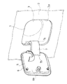
- FIG. 1 is a perspective view showing a state of use of an embodiment of the present invention, in which the lid is in a closed position.
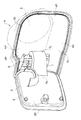
- FIG. 2 is a perspective view showing the state of use of the embodiment of the present invention, in which the lid is in the maximum open position.
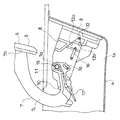
- FIG. 3 is a perspective view of an embodiment of the present invention, in which the lid is in the maximum open position.
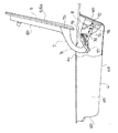
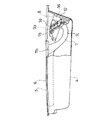
- FIG. 4 is a fragmentary side view of an essential part of one embodiment of the present invention, wherein the lid is in the maximum open position.
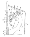
- FIG. 5 is a fragmentary side view of an essential part of an embodiment of the present invention, in which the lid is in the closed position.
- FIG. 6 is an enlarged view of an essential part of the state of FIG. FIG.
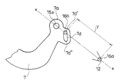
- FIG. 7 is an enlarged view of a main part of the state of FIG.
- FIG. 8 is a perspective view of an essential part of an embodiment of the present invention.
- FIG. 9 is a perspective view of a spring body.
- FIG. 10 is a side view of the main part when the lid is in the maximum open position.
- FIG. 11 is a side view of the main part when the lid is in the middle position.
- FIG. 12 is a side view of the main part when the lid is in the closed position.
- the biasing structure of the lid according to this embodiment is rotatably combined with the supply port forming body 4 provided in the automobile and forming the energy supply port 1 to close the energy supply port 1 in the closed position. While ensuring a large torque for the lid 5 at the maximum open position, the torque is reduced when the lid 5 is closed to minimize the situation where the lid 5 is suddenly closed.
- the biasing structure of the lid 5 is configured to bias the lid 5 in the closing direction in the closing position and in the opening direction in the maximum opening position with a single spring 16. The torque for the lid 5 is secured as large as possible in the maximum open position, and the torque is reduced when the lid 5 is closed, so that both the first and second requirements are satisfied. is there.
- the lid 5 blocks the energy supply port 1 (car's filler, car's power supply port of EV (electric car) or PHEV (plug-in hybrid car), hydrogen filling port of FCV (fuel cell car)) .
- the supply port forming body 4 is attached to a body of a car to form the energy supply port 1.
- the supply port forming body 4 has a bottom portion 4a and four side walls 4b surrounding the bottom portion 4a, and the bottom portion 4a of the fuel gun to the upper end of the fuel tube
- the inlet (not shown) of the nozzle is positioned, the side opposite to the bottom 4a is opened, and the opening 4c having a substantially square opening edge is communicated with the opening 2a of the body panel 2. It is designed to be attached to the body of a car.
- reference numeral 3 denotes a cap for closing the introduction port.
- the lid 5 closes the opening 4c in the closed position, and the outer surface 6a of the lid main body 6 is continuous with the outer surface of the body panel 2 (FIG. 1).
- the lid 5 is a quadrangular plate-like lid main body 6 having an outer shape following the opening edge of the open portion 4 c, the lid main body 6 and the supply port forming body 4 And an arm 7 for linking the
- the arm 7 locates the arm end 7a on one side of the two vertical sides of the lid main body 6, and the other end 7b of the arm 7 on one side of the two vertical sides. Integral to the inner surface of 6 and bending the bottom 4a side of the supply port forming body 4 in a state where the lid 5 is in the closing position with the intermediate portion 7c between the arm one end 7a and the arm other end 7b closed (FIG. 5) It has a form that is curved to be outside.
- the arm one end 7a and the arm other end 7b of the arm 7 are both positioned on the side of the opening 4c of the supply port forming body 4 when the lid 5 is in the closed position (FIG. 5).
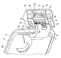
- a support 8 of an arm end 7 a of the arm 7 is formed on the inside of one of the two vertical side walls 4 b in the supply port forming body 4.
- the support portion 8 is one of two longitudinal side portions of the lid main body 6 in a state where the lid 5 is in the closed position (FIG. 5) and the fixing portion 9 for one of the two vertical side walls 4 b. And a bearing portion 11 formed on the side of the end portion 10, and a spring receiving portion 12 formed on the side of the fixed portion 9 (FIG. 6).
- the bearing portion 11 is rotatably combined with the support portion 8, that is, the supply port forming body 4, with the arm end 7a of the arm 7 by a shaft 15 having an axial center line arranged in the vertical direction. .
- the spring receiving portion 12 is formed between the bearing portion 11 and the fixing portion 9 in the supporting portion 8 and is provided on the first wall 12 a facing the bottom 4 a of the supply port forming body 4 and the first wall 12 a. On the other hand, it is formed by the second wall 12 b located on the bottom 4 a side and facing the opening 4 c of the supply port forming body 4.
- the first wall 12a and the second wall 12b are formed so as to gradually decrease the distance between the two as they approach the fixed portion 9 from the bearing 11 side, and the first wall 12a and the second wall 12b are formed.
- the wall 12 b intersects with the wall 9 so as to form a V-shape in plan view on the side of the fixing portion 9.
- the spring receiving portion 12 is formed by the intersection between the first wall 12a and the second wall 12b.
- the inside of the support part 8 is vertically divided into three by the two partitions 13 and 13 formed along the horizontal direction.
- the upper and lower dimensions of the intermediate chamber 14 between the two partitions 13 and 13 inside the support portion 8 are substantially equal to the upper and lower dimensions of the arm 7, and the arm end 7a of the arm 7 is accommodated in the intermediate chamber 14 and supported
- the portion 8 is rotatably combined with the shaft 15.
- the first wall 12a, the second wall 12b, and the spring receiver 12 are formed in the intermediate chamber 14, and the spring 16 is accommodated.
- the spring 16 links a spring end 16a to the supply port forming body 4 and links the other end 16b to the lid 5, and an intermediate position between the closed position and the maximum open position of the lid 5. In order to be most elastically deformed, the lid 5 is biased.
- the spring 16 is formed by forming a wire into an S shape (FIG. 9).
- the spring 16 is disposed between the arm end 7 a of the arm 7 and the support portion 8 in a state in which both the spring end 16 a and the spring other end 16 b are substantially parallel to the axial center line of the shaft 15. Interposed ( Figure 8).
- the spring end 16 a of the spring 16 is placed on the spring receiving portion 12 so as to be pressed from the side of the bearing portion 11 and positioned in the spring receiving portion 12.
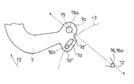
- the other spring end 16b of the spring 16 is accommodated in an elongated hole 7d formed on the side of the insertion hole 15a of the shaft 15 formed at the arm end 7a. In the illustrated example, thereby, the spring 16 and the lid 5 are linked.
- long hole 7d in arm end 7a is divided up and down, and long hole 7d is formed in upper part 7e and lower part 7f, respectively.
- the other spring end 16b of the spring 16 is inserted into the elongated hole 7d of the lower portion 7f through the elongated hole 7d of the upper portion 7e (FIG. 8).
- the spring 16 is linked to the lid 5 so as to change the distance between the other end 16 b of the spring and the rotation center of the lid 5, that is, the shaft 15.
- the width of the elongated hole 7d is substantially equal to the thickness of the other spring end 16b of the spring 16, but the length of the elongated hole 7d is larger than the thickness of the other spring end 16b.
- one end 7d 'of the long hole 7d is positioned on the arc of the virtual first circle r1 centered on the insertion hole 15a, while the other end 7d' 'of the long hole 7d is centered on the insertion hole 15a It is positioned on the arc of a virtual second circle r2 whose diameter is made larger than the virtual first circle r1 (FIG. 12).
- the distance is constant when the lid 5 is at the closed position and at the intermediate position, and increases in the course from the intermediate position to the maximum opening position and becomes maximum when the lid 5 is at the maximum opening position. It is like that.
- the one end 7d 'of the long hole 7d is positioned between the insertion hole 15a and the spring receiving portion 12 with the insertion hole 15a, the one end 7d' of the long hole 7d and the spring receiving portion 12 So that the distance y between the spring end 16a with the spring body 16 and the spring other end 16b is minimized. It has become ( Figure 11). Therefore, the most elastically deformed spring 16 presses the other end 16b of the spring against one end 7d 'of the long hole 7d.
- the long hole 7d When the lid 5 is in the closed position, the long hole 7d is located on the right side in FIG. 12 across the virtual straight line x, but in this case the distance between one end 7d 'of the long hole 7d and the spring receiving portion 12 is long The distance between the other end 7d ′ ′ of 7d and the spring receiving portion 12 is set larger (FIG. 12). Therefore, also at this time, the spring 16 presses the other end 16b of the spring against one end 7d ′ of the long hole 7d. Since the distance between one end 7d 'of the long hole 7d and the spring receiving portion 12 is narrowed as the lid 5 in the closed position is moved to the intermediate position, the lid 5 is in the closed position. A force in a closing direction indicated by a symbol f 1 in FIG. 12 is exerted on the lid 5 by the spring 16.
- the long hole 7d When the lid 5 is at the maximum open position, the long hole 7d is located on the left side in FIG. 10 across the virtual straight line, but at this time, one end 7d 'of the long hole 7d and the other end are both spring receiving portions 12 Is positioned substantially on the arc of a virtual circle r3 centered on (FIG. 10). Since the distance between the elongated hole 7d and the spring receiving portion 12 is narrowed as the lid 5 in the maximum opening position is moved to the middle position, when the lid 5 is in the maximum opening position, the spring body 16 is closed. Thus, an opening direction force indicated by a symbol f2 in FIG. 10 is applied to the lid 5.
- the spring other end 16b of the spring 16 is moved from one end 7d 'of the long hole 7d to the other end by the force in the opening direction.
- the spring 16 presses the other end 16b of the spring 16 against the other end 7d "of the elongated hole 7d by the force in the direction of opening.
- the distance between the other end 7d '' of the long hole 7d and the insertion hole 15a is larger than the distance between one end 7d 'of the long hole 7d and the insertion hole 15a. Therefore, the torque applied to the lid 5 at the maximum open position is maximum And the first request is satisfied.
- the long hole 7d is turned to gradually reduce the distance between the other end 7d of the long hole 7d and the spring receiving portion 12, and when the lid 5 reaches the middle position, the long hole The distance between one end 7d 'of 7d and the spring receiving portion 12 is larger than the distance between the other end 7d' 'of the long hole 7d and the spring receiving portion 12.
- the other spring end 16b of the spring 16 returns to one end 7d 'of the long hole 7d, and the distance between the other spring end 16b and the insertion hole 15a decreases. Therefore, between the intermediate position and the closed position, the torque of the spring 16 is reduced and the second requirement is satisfied.
- the lid 5 when the lid 5 is in the closed position, the lid 5 is locked by locking means (not shown).
- the lock means When the lock means is unlocked, the biasing force of the additional spring indicated by reference numeral 17 in FIG. 4 causes the lid 5 to float slightly at its free end side.
- the opening operation of the lid 5 in the closed position is performed by putting a finger on the free end of the lid 5 which is slightly lifted as described above.
Landscapes
- Engineering & Computer Science (AREA)
- Chemical & Material Sciences (AREA)
- Combustion & Propulsion (AREA)
- Transportation (AREA)
- Mechanical Engineering (AREA)
- Life Sciences & Earth Sciences (AREA)
- Sustainable Development (AREA)
- Sustainable Energy (AREA)
- Cooling, Air Intake And Gas Exhaust, And Fuel Tank Arrangements In Propulsion Units (AREA)
- Closures For Containers (AREA)
- Closing And Opening Devices For Wings, And Checks For Wings (AREA)
Priority Applications (4)
| Application Number | Priority Date | Filing Date | Title |
|---|---|---|---|
| CN201880052868.2A CN111032410B (zh) | 2017-08-25 | 2018-08-20 | 盖的施力结构 |
| EP18848794.6A EP3674126A4 (en) | 2017-08-25 | 2018-08-20 | STRUCTURE REQUESTED FOR COVER |
| MX2020001914A MX2020001914A (es) | 2017-08-25 | 2018-08-20 | Estructura de impulso para tapa. |
| US16/638,286 US11125000B2 (en) | 2017-08-25 | 2018-08-20 | Urging structure for lid |
Applications Claiming Priority (2)
| Application Number | Priority Date | Filing Date | Title |
|---|---|---|---|
| JP2017161817A JP6752182B2 (ja) | 2017-08-25 | 2017-08-25 | リッドの付勢構造 |
| JP2017-161817 | 2017-08-25 |
Publications (1)
| Publication Number | Publication Date |
|---|---|
| WO2019039423A1 true WO2019039423A1 (ja) | 2019-02-28 |
Family
ID=65439874
Family Applications (1)
| Application Number | Title | Priority Date | Filing Date |
|---|---|---|---|
| PCT/JP2018/030624 Ceased WO2019039423A1 (ja) | 2017-08-25 | 2018-08-20 | リッドの付勢構造 |
Country Status (6)
| Country | Link |
|---|---|
| US (1) | US11125000B2 (enExample) |
| EP (1) | EP3674126A4 (enExample) |
| JP (1) | JP6752182B2 (enExample) |
| CN (1) | CN111032410B (enExample) |
| MX (1) | MX2020001914A (enExample) |
| WO (1) | WO2019039423A1 (enExample) |
Cited By (1)
| Publication number | Priority date | Publication date | Assignee | Title |
|---|---|---|---|---|
| CN111556683A (zh) * | 2020-06-02 | 2020-08-18 | 巩国一 | 一种建筑工程给水排水监控装置 |
Families Citing this family (4)
| Publication number | Priority date | Publication date | Assignee | Title |
|---|---|---|---|---|
| JP7050539B2 (ja) * | 2018-03-15 | 2022-04-08 | 本田技研工業株式会社 | フューエルリッド構造および車体構造 |
| JP7238409B2 (ja) * | 2019-01-09 | 2023-03-14 | トヨタ自動車株式会社 | 水素充填構造 |
| WO2022075283A1 (ja) * | 2020-10-08 | 2022-04-14 | 三菱自動車工業株式会社 | 車両のリッド装置 |
| USD1044403S1 (en) * | 2022-05-17 | 2024-10-01 | Lg Electronics Inc. | Hinge for cooking appliance |
Citations (6)
| Publication number | Priority date | Publication date | Assignee | Title |
|---|---|---|---|---|
| EP0806317A1 (de) * | 1996-05-08 | 1997-11-12 | ED. SCHARWÄCHTER GmbH & Co. KG | Tankklappe mit integrierter Aufspringmechanik |
| JP2004009809A (ja) * | 2002-06-05 | 2004-01-15 | Nissan Motor Co Ltd | 車両のフューエルフィラーリッド構造 |
| JP2006264513A (ja) * | 2005-03-24 | 2006-10-05 | Nishikawa Kasei Co Ltd | 車両用収納部構造 |
| JP3959074B2 (ja) | 2004-05-11 | 2007-08-15 | 本田技研工業株式会社 | 車両のフュエルフィラーリッド構造 |
| JP2014121985A (ja) * | 2012-12-21 | 2014-07-03 | Mitsubishi Motors Corp | リッド装置 |
| JP2017161817A (ja) | 2016-03-11 | 2017-09-14 | シャープ株式会社 | 定着装置および画像形成装置 |
Family Cites Families (30)
| Publication number | Priority date | Publication date | Assignee | Title |
|---|---|---|---|---|
| US1634358A (en) * | 1925-09-05 | 1927-07-05 | Roper Corp Geo D | Oven-door mounting |
| DE952769C (de) | 1954-04-02 | 1956-11-22 | Daimler Benz Ag | Vorrichtung zum Erleichtern des OEffnens von Behaelterdeckeln, insbesondere an Kraftfahrzeugen |
| US3103693A (en) * | 1960-04-27 | 1963-09-17 | Revco Inc | Hinge mechanism |
| US3785006A (en) * | 1971-11-08 | 1974-01-15 | Audi Ag | Hinge for a cover |
| US3906587A (en) * | 1973-12-07 | 1975-09-23 | Weber Knapp Co | Lid mounting hinge and counterbalance mechanism |
| US4406379A (en) * | 1982-06-11 | 1983-09-27 | Westinghouse Electric Corp. | Cable manager |
| US4527825A (en) * | 1983-11-17 | 1985-07-09 | General Motors Corporation | Fuel filler door with dual hinge |
| US4782978A (en) * | 1987-09-03 | 1988-11-08 | General Motors Corporation | Remotely releasable fuel filler door with controlled opening |
| JP2564902B2 (ja) * | 1988-07-28 | 1996-12-18 | スズキ株式会社 | 車両のフューエルフィラドア構造 |
| US5272789A (en) * | 1992-06-09 | 1993-12-28 | Quest Engineering, Ltd. | Self-closing door hinge |
| US5488757A (en) * | 1994-09-27 | 1996-02-06 | Pitney Bowes Inc. | Counterbalance device for mail processing system cover |
| US5896619A (en) * | 1997-08-29 | 1999-04-27 | General Electric Company | Refrigerator door hinge and closure mechanism |
| JP4210923B2 (ja) * | 2003-11-21 | 2009-01-21 | 住友電装株式会社 | 車両用コンセントカバー |
| DE102004010294B4 (de) * | 2004-03-03 | 2007-05-03 | Itw Automotive Products Gmbh & Co. Kg | Tankmulde für Automobile |
| US7430785B2 (en) * | 2005-03-31 | 2008-10-07 | Honda Motor Co., Ltd. | Integrated hinge and temporary door checker |
| CA2516139C (en) * | 2005-08-15 | 2011-03-15 | Van-Rob Inc. | Automotive fuel door assembly |
| JP4947570B2 (ja) * | 2006-02-13 | 2012-06-06 | 下西技研工業株式会社 | 原稿圧着板の開閉装置 |
| JP4951550B2 (ja) * | 2008-02-22 | 2012-06-13 | 本田技研工業株式会社 | 車両の燃料給油口蓋構造 |
| JP5026594B2 (ja) * | 2008-09-01 | 2012-09-12 | 株式会社パイオラックス | フューエルリッド開閉装置 |
| KR100970472B1 (ko) * | 2008-12-12 | 2010-07-16 | 주식회사 다이아벨 | 스윙 힌지모듈 |
| DE102009034428B4 (de) * | 2009-07-23 | 2011-03-31 | Temtec Fahrzeugtechnik Entwicklungsgesellschaft Mbh | Verschluss |
| JP5585363B2 (ja) * | 2010-10-01 | 2014-09-10 | 日産自動車株式会社 | 充電ポート用カバーの配設構造 |
| CN202389200U (zh) * | 2011-12-12 | 2012-08-22 | 宁波敏实汽车零部件技术研发有限公司 | 一种加油口盖总成结构 |
| CN202573789U (zh) * | 2012-05-07 | 2012-12-05 | 神龙汽车有限公司 | 车内电动控制开启的塑料加油口盖 |
| JP6178071B2 (ja) * | 2012-12-13 | 2017-08-09 | 株式会社東海理化電機製作所 | ロック装置 |
| CN204136771U (zh) * | 2014-09-24 | 2015-02-04 | 北京长安汽车工程技术研究有限责任公司 | 一种汽车及其加油口盖结构 |
| US9227509B1 (en) * | 2014-10-06 | 2016-01-05 | Nissan North America, Inc. | Spring mounting structures for a fuel lid |
| JP6187524B2 (ja) * | 2015-04-01 | 2017-08-30 | マツダ株式会社 | 車両のフィラーリッド部構造 |
| DE102015212838A1 (de) | 2015-07-09 | 2017-01-12 | Volkswagen Aktiengesellschaft | Federkinematik zur Geräuschdämpfung beim Schließen einer Tankklappe |
| CH711418A2 (de) * | 2015-08-15 | 2017-02-15 | Schwanden Kunststoff | Tankanschluss eines Kraftfahrzeuges. |
-
2017
- 2017-08-25 JP JP2017161817A patent/JP6752182B2/ja active Active
-
2018
- 2018-08-20 US US16/638,286 patent/US11125000B2/en active Active
- 2018-08-20 EP EP18848794.6A patent/EP3674126A4/en not_active Withdrawn
- 2018-08-20 CN CN201880052868.2A patent/CN111032410B/zh active Active
- 2018-08-20 WO PCT/JP2018/030624 patent/WO2019039423A1/ja not_active Ceased
- 2018-08-20 MX MX2020001914A patent/MX2020001914A/es unknown
Patent Citations (6)
| Publication number | Priority date | Publication date | Assignee | Title |
|---|---|---|---|---|
| EP0806317A1 (de) * | 1996-05-08 | 1997-11-12 | ED. SCHARWÄCHTER GmbH & Co. KG | Tankklappe mit integrierter Aufspringmechanik |
| JP2004009809A (ja) * | 2002-06-05 | 2004-01-15 | Nissan Motor Co Ltd | 車両のフューエルフィラーリッド構造 |
| JP3959074B2 (ja) | 2004-05-11 | 2007-08-15 | 本田技研工業株式会社 | 車両のフュエルフィラーリッド構造 |
| JP2006264513A (ja) * | 2005-03-24 | 2006-10-05 | Nishikawa Kasei Co Ltd | 車両用収納部構造 |
| JP2014121985A (ja) * | 2012-12-21 | 2014-07-03 | Mitsubishi Motors Corp | リッド装置 |
| JP2017161817A (ja) | 2016-03-11 | 2017-09-14 | シャープ株式会社 | 定着装置および画像形成装置 |
Non-Patent Citations (1)
| Title |
|---|
| See also references of EP3674126A4 |
Cited By (1)
| Publication number | Priority date | Publication date | Assignee | Title |
|---|---|---|---|---|
| CN111556683A (zh) * | 2020-06-02 | 2020-08-18 | 巩国一 | 一种建筑工程给水排水监控装置 |
Also Published As
| Publication number | Publication date |
|---|---|
| MX2020001914A (es) | 2020-07-13 |
| JP2019038369A (ja) | 2019-03-14 |
| CN111032410B (zh) | 2022-11-25 |
| EP3674126A4 (en) | 2021-06-02 |
| US11125000B2 (en) | 2021-09-21 |
| CN111032410A (zh) | 2020-04-17 |
| EP3674126A1 (en) | 2020-07-01 |
| JP6752182B2 (ja) | 2020-09-09 |
| US20200173215A1 (en) | 2020-06-04 |
Similar Documents
| Publication | Publication Date | Title |
|---|---|---|
| WO2019039423A1 (ja) | リッドの付勢構造 | |
| KR20090102046A (ko) | 자동차용 도어래치의 댐핑장치 | |
| US9969308B2 (en) | Lock device | |
| JP2019209834A (ja) | リッド付勢構造 | |
| CN110271412B (zh) | 燃料箱盖构造以及车身构造 | |
| CN102561869A (zh) | 限位式加油门 | |
| JP2007106233A (ja) | アームレスト構造 | |
| JP6517410B1 (ja) | リッドロック機構およびコンソールボックス | |
| JP2017071338A (ja) | 車両用ドアトリム構造 | |
| JP2008189076A (ja) | 車両用ドア構造 | |
| JP2018021318A (ja) | 車両用ロック装置 | |
| JP5894893B2 (ja) | 収容構造体装置 | |
| JP2007274882A (ja) | 給電ユニット | |
| JP6091966B2 (ja) | コンソールドア用操作装置 | |
| JP5613479B2 (ja) | 給油口フラップ開閉装置 | |
| JP2015009578A (ja) | 車両用ポップアップフード装置 | |
| JP2018076017A (ja) | 自動車の内装ボックス | |
| JP6887782B2 (ja) | 自動車の内装ボックス | |
| JP2018047844A (ja) | 車両用収納ボックス | |
| JP6087582B2 (ja) | 車両用ドア | |
| JP2018075964A (ja) | 車両用ドアヒンジ装置 | |
| JP2024104353A (ja) | ワイヤハーネス | |
| JP2006103388A (ja) | グローブボックス構造 | |
| JP2025136326A (ja) | 蓋の取付構造 | |
| JP5586266B2 (ja) | リッド取付構造 |
Legal Events
| Date | Code | Title | Description |
|---|---|---|---|
| 121 | Ep: the epo has been informed by wipo that ep was designated in this application |
Ref document number: 18848794 Country of ref document: EP Kind code of ref document: A1 |
|
| NENP | Non-entry into the national phase |
Ref country code: DE |
|
| ENP | Entry into the national phase |
Ref document number: 2018848794 Country of ref document: EP Effective date: 20200325 |