WO2018097212A1 - 非水系二次電池用負極材、非水系二次電池用負極及び非水系二次電池 - Google Patents
非水系二次電池用負極材、非水系二次電池用負極及び非水系二次電池 Download PDFInfo
- Publication number
- WO2018097212A1 WO2018097212A1 PCT/JP2017/042108 JP2017042108W WO2018097212A1 WO 2018097212 A1 WO2018097212 A1 WO 2018097212A1 JP 2017042108 W JP2017042108 W JP 2017042108W WO 2018097212 A1 WO2018097212 A1 WO 2018097212A1
- Authority
- WO
- WIPO (PCT)
- Prior art keywords
- negative electrode
- particles
- silicon oxide
- secondary battery
- oxide particles
- Prior art date
- Legal status (The legal status is an assumption and is not a legal conclusion. Google has not performed a legal analysis and makes no representation as to the accuracy of the status listed.)
- Ceased
Links
Classifications
-
- H—ELECTRICITY
- H01—ELECTRIC ELEMENTS
- H01M—PROCESSES OR MEANS, e.g. BATTERIES, FOR THE DIRECT CONVERSION OF CHEMICAL ENERGY INTO ELECTRICAL ENERGY
- H01M4/00—Electrodes
- H01M4/02—Electrodes composed of, or comprising, active material
- H01M4/36—Selection of substances as active materials, active masses, active liquids
- H01M4/48—Selection of substances as active materials, active masses, active liquids of inorganic oxides or hydroxides
-
- H—ELECTRICITY
- H01—ELECTRIC ELEMENTS
- H01M—PROCESSES OR MEANS, e.g. BATTERIES, FOR THE DIRECT CONVERSION OF CHEMICAL ENERGY INTO ELECTRICAL ENERGY
- H01M4/00—Electrodes
- H01M4/02—Electrodes composed of, or comprising, active material
- H01M4/36—Selection of substances as active materials, active masses, active liquids
- H01M4/362—Composites
- H01M4/364—Composites as mixtures
-
- H—ELECTRICITY
- H01—ELECTRIC ELEMENTS
- H01M—PROCESSES OR MEANS, e.g. BATTERIES, FOR THE DIRECT CONVERSION OF CHEMICAL ENERGY INTO ELECTRICAL ENERGY
- H01M4/00—Electrodes
- H01M4/02—Electrodes composed of, or comprising, active material
- H01M4/13—Electrodes for accumulators with non-aqueous electrolyte, e.g. for lithium-accumulators; Processes of manufacture thereof
- H01M4/131—Electrodes based on mixed oxides or hydroxides, or on mixtures of oxides or hydroxides, e.g. LiCoOx
-
- H—ELECTRICITY
- H01—ELECTRIC ELEMENTS
- H01M—PROCESSES OR MEANS, e.g. BATTERIES, FOR THE DIRECT CONVERSION OF CHEMICAL ENERGY INTO ELECTRICAL ENERGY
- H01M10/00—Secondary cells; Manufacture thereof
- H01M10/05—Accumulators with non-aqueous electrolyte
- H01M10/052—Li-accumulators
-
- H—ELECTRICITY
- H01—ELECTRIC ELEMENTS
- H01M—PROCESSES OR MEANS, e.g. BATTERIES, FOR THE DIRECT CONVERSION OF CHEMICAL ENERGY INTO ELECTRICAL ENERGY
- H01M10/00—Secondary cells; Manufacture thereof
- H01M10/05—Accumulators with non-aqueous electrolyte
- H01M10/056—Accumulators with non-aqueous electrolyte characterised by the materials used as electrolytes, e.g. mixed inorganic/organic electrolytes
- H01M10/0564—Accumulators with non-aqueous electrolyte characterised by the materials used as electrolytes, e.g. mixed inorganic/organic electrolytes the electrolyte being constituted of organic materials only
- H01M10/0566—Liquid materials
- H01M10/0567—Liquid materials characterised by the additives
-
- H—ELECTRICITY
- H01—ELECTRIC ELEMENTS
- H01M—PROCESSES OR MEANS, e.g. BATTERIES, FOR THE DIRECT CONVERSION OF CHEMICAL ENERGY INTO ELECTRICAL ENERGY
- H01M4/00—Electrodes
- H01M4/02—Electrodes composed of, or comprising, active material
- H01M4/13—Electrodes for accumulators with non-aqueous electrolyte, e.g. for lithium-accumulators; Processes of manufacture thereof
- H01M4/133—Electrodes based on carbonaceous material, e.g. graphite-intercalation compounds or CFx
-
- H—ELECTRICITY
- H01—ELECTRIC ELEMENTS
- H01M—PROCESSES OR MEANS, e.g. BATTERIES, FOR THE DIRECT CONVERSION OF CHEMICAL ENERGY INTO ELECTRICAL ENERGY
- H01M4/00—Electrodes
- H01M4/02—Electrodes composed of, or comprising, active material
- H01M4/36—Selection of substances as active materials, active masses, active liquids
-
- H—ELECTRICITY
- H01—ELECTRIC ELEMENTS
- H01M—PROCESSES OR MEANS, e.g. BATTERIES, FOR THE DIRECT CONVERSION OF CHEMICAL ENERGY INTO ELECTRICAL ENERGY
- H01M4/00—Electrodes
- H01M4/02—Electrodes composed of, or comprising, active material
- H01M4/36—Selection of substances as active materials, active masses, active liquids
- H01M4/38—Selection of substances as active materials, active masses, active liquids of elements or alloys
-
- H—ELECTRICITY
- H01—ELECTRIC ELEMENTS
- H01M—PROCESSES OR MEANS, e.g. BATTERIES, FOR THE DIRECT CONVERSION OF CHEMICAL ENERGY INTO ELECTRICAL ENERGY
- H01M4/00—Electrodes
- H01M4/02—Electrodes composed of, or comprising, active material
- H01M4/36—Selection of substances as active materials, active masses, active liquids
- H01M4/38—Selection of substances as active materials, active masses, active liquids of elements or alloys
- H01M4/386—Silicon or alloys based on silicon
-
- H—ELECTRICITY
- H01—ELECTRIC ELEMENTS
- H01M—PROCESSES OR MEANS, e.g. BATTERIES, FOR THE DIRECT CONVERSION OF CHEMICAL ENERGY INTO ELECTRICAL ENERGY
- H01M4/00—Electrodes
- H01M4/02—Electrodes composed of, or comprising, active material
- H01M4/36—Selection of substances as active materials, active masses, active liquids
- H01M4/48—Selection of substances as active materials, active masses, active liquids of inorganic oxides or hydroxides
- H01M4/483—Selection of substances as active materials, active masses, active liquids of inorganic oxides or hydroxides for non-aqueous cells
-
- H—ELECTRICITY
- H01—ELECTRIC ELEMENTS
- H01M—PROCESSES OR MEANS, e.g. BATTERIES, FOR THE DIRECT CONVERSION OF CHEMICAL ENERGY INTO ELECTRICAL ENERGY
- H01M4/00—Electrodes
- H01M4/02—Electrodes composed of, or comprising, active material
- H01M4/36—Selection of substances as active materials, active masses, active liquids
- H01M4/58—Selection of substances as active materials, active masses, active liquids of inorganic compounds other than oxides or hydroxides, e.g. sulfides, selenides, tellurides, halogenides or LiCoFy; of polyanionic structures, e.g. phosphates, silicates or borates
- H01M4/583—Carbonaceous material, e.g. graphite-intercalation compounds or CFx
- H01M4/587—Carbonaceous material, e.g. graphite-intercalation compounds or CFx for inserting or intercalating light metals
-
- H—ELECTRICITY
- H01—ELECTRIC ELEMENTS
- H01M—PROCESSES OR MEANS, e.g. BATTERIES, FOR THE DIRECT CONVERSION OF CHEMICAL ENERGY INTO ELECTRICAL ENERGY
- H01M10/00—Secondary cells; Manufacture thereof
- H01M10/05—Accumulators with non-aqueous electrolyte
- H01M10/052—Li-accumulators
- H01M10/0525—Rocking-chair batteries, i.e. batteries with lithium insertion or intercalation in both electrodes; Lithium-ion batteries
-
- H—ELECTRICITY
- H01—ELECTRIC ELEMENTS
- H01M—PROCESSES OR MEANS, e.g. BATTERIES, FOR THE DIRECT CONVERSION OF CHEMICAL ENERGY INTO ELECTRICAL ENERGY
- H01M4/00—Electrodes
- H01M4/02—Electrodes composed of, or comprising, active material
- H01M2004/021—Physical characteristics, e.g. porosity, surface area
-
- H—ELECTRICITY
- H01—ELECTRIC ELEMENTS
- H01M—PROCESSES OR MEANS, e.g. BATTERIES, FOR THE DIRECT CONVERSION OF CHEMICAL ENERGY INTO ELECTRICAL ENERGY
- H01M4/00—Electrodes
- H01M4/02—Electrodes composed of, or comprising, active material
- H01M2004/026—Electrodes composed of, or comprising, active material characterised by the polarity
- H01M2004/027—Negative electrodes
-
- Y—GENERAL TAGGING OF NEW TECHNOLOGICAL DEVELOPMENTS; GENERAL TAGGING OF CROSS-SECTIONAL TECHNOLOGIES SPANNING OVER SEVERAL SECTIONS OF THE IPC; TECHNICAL SUBJECTS COVERED BY FORMER USPC CROSS-REFERENCE ART COLLECTIONS [XRACs] AND DIGESTS
- Y02—TECHNOLOGIES OR APPLICATIONS FOR MITIGATION OR ADAPTATION AGAINST CLIMATE CHANGE
- Y02E—REDUCTION OF GREENHOUSE GAS [GHG] EMISSIONS, RELATED TO ENERGY GENERATION, TRANSMISSION OR DISTRIBUTION
- Y02E60/00—Enabling technologies; Technologies with a potential or indirect contribution to GHG emissions mitigation
- Y02E60/10—Energy storage using batteries
Definitions
- the present invention relates to a negative electrode material for a non-aqueous secondary battery, a negative electrode for a non-aqueous secondary battery using the same, and a non-aqueous secondary battery including the negative electrode.
- non-aqueous secondary batteries having higher energy density and excellent rapid charge / discharge characteristics are attracting attention as compared to nickel / cadmium batteries and nickel / hydrogen batteries.
- positive and negative electrodes capable of receiving and releasing lithium ions and nonaqueous lithium secondary batteries made of a nonaqueous electrolyte solution in which lithium salts such as LiPF 6 and LiBF 4 are dissolved have been developed and put into practical use.
- Various negative electrode materials have been proposed for this non-aqueous lithium secondary battery.
- natural graphite and coke can be graphitized.
- Graphitic carbonaceous particles such as artificial graphite, graphitized mesophase pitch, and graphitized carbon fiber are used.
- Amorphous carbon materials are also used because they are relatively stable with respect to some electrolyte solutions.
- the amorphous carbon is coated or adhered to the surface of the graphite particles, and there are two characteristics: a high capacity and low irreversible capacity due to graphite, and excellent stability with an electrolyte solution due to amorphous carbon. Carbon materials with combined characteristics are also used.
- Patent Document 1 describes a carbonaceous particle using carbonaceous particles having a carbon layer on at least a part of the surface of graphite particles.
- Patent Document 2 describes a carbonaceous particle using a mixture of spheroidized graphite and scaly graphite.
- Patent Document 3 describes a negative electrode active material using a combination of graphite and a silicon oxide material in which a silicon oxide material is blended in a large amount of 17 to 40% by mass.
- Patent Document 4 describes a combination of graphite and non-graphitizable carbon particles as carbonaceous particles and a silicon oxide material.
- an object of the present invention is to provide a non-aqueous secondary battery negative electrode material that can provide a non-aqueous secondary battery having high capacity and excellent rate characteristics during discharging, and a non-aqueous secondary battery using the same. It is providing the negative electrode for batteries and a non-aqueous secondary battery. Another object of the present invention is to provide a non-aqueous secondary battery having excellent charge / discharge efficiency.
- the gist of the present invention is as follows.
- a negative electrode material for a non-aqueous secondary battery that includes carbonaceous particles (A) and silicon oxide particles (B) and satisfies the following a) to c).
- a) Average particle diameter (particle diameter of 50% integrated part from the small particle side) (d50) is 3 ⁇ m or more and 30 ⁇ m or less, and particle diameter (d10) of 10% integrated part from the small particle side is 0.1 ⁇ m or more and 10 ⁇ m or less
- the d50 a of the carbonaceous particles (A) is 5 ⁇ m or more and 30 ⁇ m or less, the particle diameter of the 90% integration part from the small particle side (d90 a ) and the particle diameter of the 10% integration part from the small particle side (d10 a )
- the d50 b of the silicon oxide particles (B) is 0.1 ⁇ m or more and 20 ⁇ m or less, the particle diameter (d90 b ) of the 90% integrated part from the small particle side and the particle diameter (d10) of the 10% integrated part from the small particle side.
- the negative electrode material for a non-aqueous secondary battery according to any one of [6].
- the ratio (M O / M Si ) of the number of oxygen atoms (M O ) to the number of silicon atoms (M Si ) in the silicon oxide particles (B) is 0.5 to 1.6, [1] to [ 9]
- the negative electrode material for nonaqueous secondary batteries according to any one of [9].
- a negative electrode for a non-aqueous secondary battery comprising a current collector and an active material layer formed on the current collector, wherein the active material layer is any one of [1] to [12]
- a negative electrode for a nonaqueous secondary battery comprising the negative electrode material for a nonaqueous secondary battery described.
- a nonaqueous secondary battery comprising a positive electrode and a negative electrode, and an electrolyte, wherein the negative electrode is the negative electrode for a nonaqueous secondary battery according to [13].
- the negative electrode material for non-aqueous secondary batteries which is high capacity
- the average particle size of the negative electrode material for non-aqueous secondary batteries of the present invention (particle size of 50% integration part from the small particle side). ) Is simply referred to as “d50”, the particle diameter of the 10% integration part from the small particle side is simply referred to as “d10”, and the particle diameter of the 90% integration part from the small particle side is simply referred to as “d90”.
- d50 particle size of the negative electrode material for non-aqueous secondary batteries of the present invention
- the average particle diameter of the carbonaceous particles (A) used in the present invention (the particle diameter of the 50% integrated part from the small particle side) is simply referred to as “d50 a ”, and the particle diameter of the 10% integrated part from the small particle side is In some cases, it is simply referred to as “d10 a ”, and the particle diameter of the 90% integration portion from the small particle side is simply referred to as “d90 a ”.
- the average particle diameter of the silicon oxide particles (B) used in the present invention (the particle diameter of the 50% integrated part from the small particle side) is simply referred to as “d50 b ”, and the particle diameter of the 10% integrated part from the small particle side is In some cases, it is simply referred to as “d10 b ”, and the particle diameter of the 90% integrating portion from the small particle side is simply referred to as “d90 b ”.
- d50, d10, d90, d50 a , d10 a, d90 a, d50 b, d10 b, d90 b is the method described in the Examples given later, as measured in accordance with volume-based particle size distribution Value.
- the negative electrode material of the present invention contains carbonaceous particles (A) and silicon oxide particles (B) and satisfies the following a) to c).
- a) Average particle diameter (particle diameter of 50% integrated part from the small particle side) (d50) is 3 ⁇ m or more and 30 ⁇ m or less, and particle diameter (d10) of 10% integrated part from the small particle side is 0.1 ⁇ m or more and 10 ⁇ m or less
- the negative electrode material of the present invention satisfying the above a) to c) has the characteristics that the particle size distribution is broad and there are many fine powders (in the particle size distribution chart, a band is drawn on the fine powder side).
- the particle size distribution broad it is possible to obtain a large discharge capacity because the contact between the particles increases when the small particles are present between the large particles, and the conduction path is cut off.
- the fine powder side is large (distributed shape with a strip), the effect of improving the contact property is improved, and even if the silicon oxide particles (B) are greatly expanded and contracted, the conductive path is hardly cut and a large discharge capacity is obtained.
- the negative electrode material of the present invention includes not only a large amount of fine powder but also a material having a large particle diameter, and the particle size distribution is broad, so that an electrolyte channel is appropriately formed inside the negative electrode active material layer. Therefore, the discharge rate characteristics are good.
- ⁇ Operational effect based on containing silicon oxide particles (B)> By including high-capacity silicon oxide particles (B), a high-capacity negative electrode material can be obtained.
- the ratio (M O / M Si ) of the number of oxygen atoms (M O ) to the number of silicon atoms (M Si ) in the silicon oxide particles (B) is 0.5 to 1.6, resulting in high capacity.
- the volume change amount due to the reception and release of Li ions is small, close to the volume change amount of the carbonaceous particles (A), and the performance deterioration due to the loss of contact with the carbonaceous particles (A) is reduced. It becomes possible.
- the silicon oxide particles (B) contain zero-valent silicon atoms, the potential range for accepting and releasing Li ions is close to that of the carbonaceous particles (A), and the volume change associated with accepting and releasing Li ions. Occurs at the same time as the carbonaceous particles (A), so that the interface between the carbonaceous particles (A) and the silicon oxide particles (B) is less likely to be displaced, and the contact with the carbonaceous particles (A) is impaired. Can be reduced.
- d50 of the negative electrode material of the present invention is 3 ⁇ m or more, an increase in irreversible capacity due to an increase in specific surface area can be prevented.
- d50 is 30 ⁇ m or less, it is possible to prevent the rapid charge / discharge performance from being lowered due to the decrease in the contact area between the electrolyte and the negative electrode material particles.
- d50 is preferably 8 to 27 ⁇ m, more preferably 10 to 25 ⁇ m, and particularly preferably 12 to 23 ⁇ m.
- d10 of the negative electrode material of the present invention is 0.1 ⁇ m or more, an increase in specific surface area due to excessive inclusion of fine particles can be suppressed, and irreversible capacity can be reduced.
- d10 is 10 ⁇ m or less, the above-described effects due to containing a large amount of fine powder can be obtained.
- d10 is preferably 0.5 to 9 ⁇ m, more preferably 1 to 8 ⁇ m, and still more preferably 3 to 7 ⁇ m.
- the d90 of the negative electrode material of the present invention can prevent generation of process defects such as electrode striation due to increase of coarse particles, deterioration of high current density charge / discharge characteristics, and deterioration of low temperature input / output characteristics, and is reasonably large. From the viewpoint of ensuring a space where small particles can be present by making particles present to improve discharge capacity, and preventing a decrease in negative electrode strength and a decrease in initial charge / discharge efficiency, it is 10 ⁇ m or more and 100 ⁇ m or less. Is more preferably 15 to 60 ⁇ m, still more preferably 20 to 40 ⁇ m.
- the tap density of the negative electrode material of the present invention is preferably 0.8 to 1.8 g / cm 3 , more preferably 0.9 to 1.7 g / cm 3 , still more preferably 1.0 to 1.6 g ⁇ cm 3. It is.
- the tap density is within the above range, the electrolyte and the silicon oxide particles (B) can be present in the gaps formed by the carbonaceous particles (A) when the negative electrode is formed. Characterization can be made easier.
- the tap density is measured by the method described in the example section below.
- the specific surface area by the BET method of the negative electrode material of the present invention is usually 0.5 m 2 / g or more, preferably 2 m 2 / g or more, more preferably 3 m 2 / g or more, still more preferably 4 m 2 / g or more, particularly preferably. Is 5 m 2 / g or more.
- it is 11 m ⁇ 2 > / g or less normally, Preferably it is 9 m ⁇ 2 > / g or less, More preferably, it is 8 m ⁇ 2 > / g or less, More preferably, it is 7 m ⁇ 2 > / g or less, Especially preferably, it is 6.5 m ⁇ 2 > / g or less.
- the specific surface area is not less than the above lower limit, it is easy to secure a site where Li enters and exits, which is preferable from the viewpoint of high-speed charge / discharge characteristics, output characteristics, and low-temperature input / output characteristics of the lithium ion secondary battery.
- the specific surface area is less than or equal to the above upper limit, the activity of the active material with respect to the electrolytic solution is suppressed to an appropriate range, and the initial charge / discharge efficiency of the battery is reduced due to an increase in side reaction with the electrolytic solution and the amount of gas generated is increased. It tends to be easy to prevent the battery capacity from decreasing.
- the specific surface area by the BET method is measured by the method described in the Examples section below.
- the volume change of the silicon oxide particles (B) due to the acceptance / release of alkali ions such as Li ions due to charge / discharge is absorbed by the gap formed by the carbonaceous particles (A), so the volume of the silicon oxide particles (B). It is possible to suppress disconnection of the conductive path due to the change, and as a result, it is possible to improve cycle characteristics, rapid charge / discharge characteristics, and increase in capacity.
- R3 d50 b / d50 a is more preferably 0.05 to 0.9, further preferably 0.1 to 0.85, and particularly preferably 0.15 to 0.8 from the above viewpoint.
- R4 d50 b / d10 a is such that the average particle diameter d50 b of the silicon oxide particles (B) is not more than twice the d10 a of the carbonaceous particles (A) within the above range, the carbonaceous particles ( A) It becomes easy to obtain the above-mentioned effect due to the carbonaceous particles (A) entering the gaps between them.
- R1 b d90 b / d10 b >
- R1 b d90 b / d10 b is more preferably 5 to 12 and even more preferably 5.5 to 10 from the above viewpoint.
- the d50 a of the carbonaceous particles (A) used in the present invention is preferably 5 ⁇ m or more and 30 ⁇ m or less.
- the d50 a of the carbonaceous particles (A) is 5 ⁇ m or more, an increase in irreversible capacity due to an increase in specific surface area can be prevented.
- the d50 a of the carbonaceous particles (A) is 30 ⁇ m or less, in the lithium ion secondary battery, it is possible to prevent a rapid charge / discharge deterioration due to a decrease in the contact area between the electrolyte and the negative electrode material particles. it can.
- D50 a carbonaceous particle (A) from the viewpoint described above more preferably 8 ⁇ 27 [mu] m, more preferably 10 ⁇ 25 [mu] m, particularly preferably 12 ⁇ 23 .mu.m.
- the d10 a of the carbonaceous particles (A) used in the present invention is preferably 1 ⁇ m or more and 15 ⁇ m or less.
- d10 a is 1 ⁇ m or more, process inconveniences such as an increase in slurry viscosity, electrode strength and initial charge / discharge efficiency can be prevented.
- it is 15 ⁇ m or less, high current density charge / discharge of the battery is prevented. It is possible to prevent deterioration of characteristics and low temperature input / output characteristics.
- d10 a of the carbonaceous particles (A) is more preferably 3 to 10 ⁇ m, further preferably 5 to 9 ⁇ m, and particularly preferably 6 to 8 ⁇ m.
- D90 a carbonaceous particle (A) used in the present invention is preferably 10 ⁇ m or more 100 ⁇ m or less.
- d90 a is 10 ⁇ m or more, it is possible to prevent a decrease in negative electrode strength and a decrease in initial charge / discharge efficiency.
- d90 a is 100 ⁇ m or less, process inconveniences such as stringing occur, and high current density charge / discharge characteristics of the battery. And lowering of low temperature input / output characteristics can be prevented.
- From viewpoint d90 a of the carbonaceous particles (A) more preferably from 15 ⁇ 60 [mu] m, more preferably 17 ⁇ 40 [mu] m, particularly preferably 20 ⁇ 30 [mu] m.
- D50 b of the silicon oxide particles (B) used in the present invention is preferably 0.1 ⁇ m or more 20 ⁇ m or less. If d50 b of the silicon oxide particles (B) is in the above range, the silicon oxide particles (B) are present in the gaps formed by the carbonaceous particles (A) in the case of an electrode, and Li ions and the like due to charge / discharge The gap absorbs the volume change of the silicon oxide particles (B) accompanying the acceptance / release of alkali ions, and the conduction path cut off due to the volume change is suppressed, and as a result, the cycle characteristics can be improved.
- the d50 b of the silicon oxide particles (B) From these viewpoints, more preferably 0.3 ⁇ 15 [mu] m, more preferably 0.4 ⁇ 10 [mu] m, particularly preferably 0.5 ⁇ 8 [mu] m.
- D10 b of the silicon oxide particles (B) used in the present invention is preferably at 6 ⁇ m inclusive 0.001 [mu] m.
- an appropriate fine powder is present, so that the silicon oxide particles (B) existing in the gaps between the carbonaceous particles (A) provide a good conductive path. It can be formed, the cycle characteristics become good, and the irreversible capacity can be reduced by suppressing an increase in specific surface area.
- D90 b of the silicon oxide particles (B) used in the present invention is preferably 0.5 ⁇ m or more 30 ⁇ m or less.
- the silicon oxide particles (B) is likely to exist in the gap between the carbonaceous particles (A), it is possible to form good electrically conductive paths, the cycle characteristics can be improved.
- the d90 b of the silicon oxide particles (B) From these viewpoints, more preferably 0.8 ⁇ 20 [mu] m, more preferably 1 ⁇ 15 [mu] m, particularly preferably 1.2 ⁇ 12 [mu] m.
- the carbonaceous particles (A) used in the present invention preferably have a circularity of 0.88 or more determined by flow-type particle image analysis measured by the method described in the Examples section below.
- the carbonaceous particles (A) having a high degree of circularity the high current density charge / discharge characteristics can be enhanced.
- the method for improving the degree of circularity of the carbonaceous particles (A) is not particularly limited, but a spherical shape obtained by applying a spheroidizing treatment is preferable because the shape of the interparticle voids when the electrode body is formed.
- spheroidizing methods include mechanically approaching a sphere by applying shearing force and compressive force, mechanical / physical processing method that granulates a plurality of fine particles by the adhesive force of the binder or the particles themselves, etc. Is mentioned.
- the circularity of the carbonaceous particles (A) is preferably 0.9 or more, particularly preferably 0.92 or more. Also, it is usually 1 or less, preferably 0.98 or less, more preferably 0.95 or less. If the circularity is too low, the high current density charge / discharge characteristics tend to decrease. On the other hand, if the circularity is too high, it becomes a true sphere, so that the contact area between the carbonaceous particles (A) decreases, and the cycle characteristics of the lithium ion secondary battery obtained by using it may deteriorate. There is.
- the tap density of the carbonaceous particles (A) used in the present invention is usually 0.50 g / cm 3 or more, preferably 0.75 g / cm 3 or more, more preferably 0.85 g / cm 3 or more, and still more preferably 0. .90 g / cm 3 or more. Also, typically 1.40 g / cm 3 or less, preferably 1.35 g / cm 3 or less, more preferably 1.20 g / cm 3 or less, still more preferably at 1.10 g / cm 3 or less.
- the packing density of the carbonaceous particles (A) used in the present invention is hardly increased, and it tends to be difficult to obtain a high-capacity lithium ion secondary battery.
- the tap density is less than or equal to the above upper limit value, voids between particles in the electrode do not decrease too much, and it becomes easy to ensure conductivity between particles, and it is easy to obtain preferable battery characteristics.
- the tap density is measured by the method described in the example section below.
- BET specific surface area of the carbonaceous particles (A) used in the present invention is usually 0.5 m 2 / g or more, preferably 1 m 2 / g or more, more preferably 2m 2 / g or more, more preferably 3m 2 / g or more, particularly preferably 4 m 2 / g or more.
- it is 30 m ⁇ 2 > / g or less normally, Preferably it is 20 m ⁇ 2 > / g or less, More preferably, it is 10 m ⁇ 2 > / g or less, More preferably, it is 7 m ⁇ 2 > / g or less, Especially preferably, it is 6.5 m ⁇ 2 > / g or less.
- the specific surface area is below this range, there are few sites where Li enters and exits, and the high-speed charge / discharge characteristics, output characteristics, and low-temperature input / output characteristics of the lithium ion secondary battery are poor.
- the specific surface area exceeds this range, the active material The activity with respect to the electrolyte solution becomes excessive, and an increase in the side reaction with the electrolyte solution causes a decrease in the initial charge / discharge efficiency of the battery and an increase in the amount of gas generated, and the battery capacity tends to decrease.
- the specific surface area by the BET method is measured by the method described in the Examples section below.
- the carbonaceous particles (A) used in the present invention preferably have an interplanar spacing d value (interlayer distance (d002)) of 0.338 nm or less of the lattice plane (002 plane) determined by X-ray wide angle diffraction by the Gakushin method. More preferably, it is 0.337 or less.
- d002 value is too large, it indicates that the crystallinity of the carbonaceous particles (A) is low, and the initial irreversible capacity of the lithium ion secondary battery may increase.
- the theoretical value of the interplanar spacing of the 002 plane of the carbonaceous particles (A) is 0.335 nm, and is usually 0.335 nm or more.
- the crystallite size (Lc) of the carbonaceous particles (A) used in the present invention determined by X-ray wide angle diffraction by the Gakushin method is usually in the range of 1.5 nm or more, preferably 3.0 nm or more. Below this range, the particles have low crystallinity and the reversible capacity of the lithium ion secondary battery may be reduced. The lower limit is the theoretical value of graphite. (D002) and (Lc) can be measured by the method described in Examples below.
- the Raman R value of the carbonaceous particles (A) used in the present invention is usually 0.01 or more, preferably 0.05 or more, more preferably 0.10 or more, and further preferably 0.20 or more. Moreover, it is 1.00 or less normally, Preferably it is 0.70 or less, More preferably, it is 0.40 or less, More preferably, it is 0.35 or less.
- the Raman R value is too small, the particle surface is not sufficiently damaged in the mechanical energy treatment of the graphite particles and the like in the production process of the carbonaceous particles (A) used in the present invention. For this reason, in the carbonaceous particles (A), the amount of Li ion accepting or releasing sites such as fine cracks and defects on the surface of the graphite particles and the like due to damage and structural defects is small. In this case, the rapid charge / discharge property of Li ions may deteriorate.
- the large Raman R value means that, for example, the amount of amorphous carbon covering the graphite particles or the like is large, and / or the surface of the graphite particles or the like due to excessive mechanical energy treatment is fine. This indicates that the amount of cracks, defects, and structural defects is too large. If the Raman R value is too large, the influence of irreversible capacity of amorphous carbon increases, and side reactions with the electrolyte increase. The initial charge / discharge efficiency of the secondary battery is reduced and the amount of gas generated is increased, and the battery capacity tends to decrease.
- the Raman spectrum can be measured with a Raman spectrometer. Specifically, the sample particles are naturally dropped into the measurement cell to fill the sample, and the measurement cell is rotated in a plane perpendicular to the laser beam while irradiating the measurement cell with an argon ion laser beam. Measure. Argon ion laser light wavelength: 514.5 nm Laser power on sample: 25 mW Resolution: 4cm -1 Measurement range: 1100 cm ⁇ 1 to 1730 cm ⁇ 1 Peak intensity measurement, peak half-width measurement: background processing, smoothing processing (convolution 5 points by simple averaging)
- the specific surface area by the BET method of the silicon oxide particles (B) used in the present invention is preferably 80 m 2 / g or less, and more preferably 60 m 2 / g or less. Moreover, it is preferable that it is 0.5 m ⁇ 2 > / g or more, It is more preferable that it is 1 m ⁇ 2 > / g or more, It is still more preferable that it is 1.5 m ⁇ 2 > / g or more.
- the specific surface area of the silicon oxide particles (B) by the BET method is within the above range, the input / output efficiency of alkali ions such as lithium ions can be maintained well, and the silicon oxide particles (B) have a suitable size. And can be present in the gap formed by the carbonaceous particles (A), and a conductive path with the carbonaceous particles (A) can be ensured. Further, since the silicon oxide particles (B) have a suitable size, an increase in irreversible capacity can be suppressed and a high capacity can be secured.
- the specific surface area by the BET method is measured by the method described in the Examples section below.
- the ratio (M O / M Si ) of the number of oxygen atoms (M O ) to the number of silicon atoms (M Si ) in the silicon oxide particles (B) used in the present invention is 0.5. It is preferable that it is -1.6. Further, it preferably contains a zero-valent silicon atom. Further, it is preferable to include crystallized silicon microcrystals.
- M O / M Si is more preferably 0.7 to 1.3, and particularly preferably 0.8 to 1.2.
- the capacity is higher than that of the carbonaceous particles (A) due to particles made of highly active amorphous silicon oxide in which alkaline ions such as Li ions easily enter and exit. And a high cycle retention ratio can be achieved by the amorphous structure.
- the silicon oxide particles (B) are filled while ensuring the contact with the carbonaceous particles (A) in the gaps formed by the carbonaceous particles (A), so that alkali ions such as Li ions by charging and discharging are provided. It is possible to absorb the change in volume of the silicon oxide particles (B) accompanying the acceptance / release of the silicon oxide through the gap. As a result, it is possible to suppress the conduction path interruption due to the volume change of the silicon oxide particles (B).
- the silicon oxide particles (B) containing a zero-valent silicon atom usually have a peak of ⁇ 100 to ⁇ 120 ppm, especially in the vicinity of ⁇ 110 ppm present in silicon oxide in solid-state NMR ( 29 Si-DDMAS) measurement.
- the broad peak (P1) in the range it is preferable that there is a broad peak (P2) centered at -70 ppm, and in particular the peak apex is in the range of -65 to -85 ppm.
- the area ratio (P2) / (P1) of these peaks is preferably 0.1 ⁇ (P2) / (P1) ⁇ 1.0, and 0.2 ⁇ (P2) / (P1) ⁇ 0.
- a range of 8 is more preferable.
- the silicon oxide particles (B) containing zero-valent silicon atoms generate hydrogen when an alkali hydroxide is allowed to act thereon.
- the amount of zero-valent silicon atoms in the silicon oxide particles (B) converted from the amount of hydrogen generated at this time is preferably 2 to 45% by weight, more preferably about 5 to 36% by weight. More preferably, it is about ⁇ 30% by weight. If the amount of zero-valent silicon atoms is less than 2% by weight, the charge / discharge capacity may be small, and conversely if it exceeds 45% by weight, the cycle characteristics may be deteriorated.
- the silicon oxide particles (B) containing silicon microcrystals preferably have the following properties.
- the particle diameter of the silicon crystal determined by the Scherrer equation is preferably 1 to 500 nm, more preferably 2 to 200 nm, and still more preferably 2 to 20 nm. If the size of the silicon fine particles is smaller than 1 nm, the charge / discharge capacity may be reduced. Conversely, if the silicon fine particle is larger than 500 nm, expansion / contraction during charge / discharge is increased, and the cycle characteristics may be deteriorated. The size of the silicon fine particles can be measured by a transmission electron micrograph.
- the amount of silicon microcrystals in the silicon oxide particles (B) is preferably 2 to 45% by weight, more preferably about 5 to 36% by weight, and still more preferably about 10 to 30% by weight.
- the amount of microcrystals of silicon is less than 2% by weight, the charge / discharge capacity may be reduced.
- the cycle characteristics may be inferior.
- the carbonaceous particles (A) used in the present invention may be constituted by one kind of carbonaceous particles as follows, or may be constituted by mixing two or more kinds of carbonaceous particles. However, carbonaceous particles (A) having high circularity containing spheroidized graphite can be obtained.
- the carbonaceous particles (A) used in the present invention include graphite particles containing natural graphite and / or artificial graphite as raw materials, or coal-based coke, petroleum-based coke, furnace black having a slightly lower crystallinity than these. It is preferable to use a material containing a fired product and / or graphitized material selected from the group consisting of acetylene black and pitch-based carbon fiber, and other commercially available anode active materials that are readily available commercially. It is more preferable to use graphitic particles containing natural graphite as a raw material in that the effect of improving the charge / discharge characteristics at a high current density is remarkably greater than in the case of using the natural graphite.
- the carbonaceous particles (A) used in the present invention having a broad particle size distribution can be produced by performing the following steps 1 and 2 using these raw materials.
- Process 1 Process of producing scaly graphite having different average particle diameter (d50) by pulverization and classification
- Process 2 Spherical graphite produced in step 1 from a small particle size product (for example, an average particle size (d50) of 5 to 50 ⁇ m) to a large particle size product (for example, an average particle size (d50) of 51 to 500 ⁇ m) Process of spheroidizing while sequentially feeding into the sizing device
- a small particle size product for example, an average particle size (d50) of 5 to 50 ⁇ m
- a large particle size product for example, an average particle size (d50) of 51 to 500 ⁇ m
- the apparatus used for the pulverization process in step 1 is not particularly limited.
- the coarse pulverizer include a shearing mill, a jaw crusher, an impact crusher, and a cone crusher.
- Examples of the intermediate pulverizer include a roll crusher and a hammer mill.
- Examples of the pulverizer include a ball mill, a vibration mill, a pin mill, a stirring mill, and a jet mill. As appropriate, classification treatment is performed to produce flake graphite having different particle sizes.
- step 2 is performed on the scaly graphite obtained in step 1.
- an apparatus used for the spheroidizing treatment in step 2 for example, an apparatus that repeatedly gives mechanical action such as compression, friction, shearing force and the like including mainly the impact force and the interaction of particles to the particles can be used. Specifically, it has a rotor with a large number of blades installed inside the casing, and when the rotor rotates at high speed, mechanical properties such as impact compression, friction, and shear force are applied to the flake graphite introduced inside. An apparatus that imparts an action and performs surface treatment is preferable.
- the device has a mechanism that repeatedly gives mechanical action by circulating scale-like graphite.
- Preferred devices include, for example, a hybridization system (manufactured by Nara Machinery Co., Ltd.), a kryptron (manufactured by Earth Technica), a CF mill (manufactured by Ube Industries), a mechano-fusion system (manufactured by Hosokawa Micron), and a theta composer (Tokuju Kosakusho). Etc.).
- a hybridization system manufactured by Nara Machinery Co., Ltd. is preferable.
- the flaky graphite is folded, and spheroidized graphite having a high degree of circularity is obtained.
- the peripheral speed of the rotating rotor is preferably set to 30 to 100 m / sec, more preferably set to 40 to 100 m / sec, and more preferably 50 to 100 m / sec. More preferably, it is set to.
- the treatment can be performed simply by passing the flake graphite through the apparatus, but it is preferable to circulate or stay in the apparatus for 30 seconds or more, and circulate or stay in the apparatus for 1 minute or more.
- the treatment is more preferable because the circularity of the obtained spheroidized graphite is improved.
- carbonaceous particles (A) having a broad particle size distribution can be produced by using the spheroidized graphite as a raw material and coating at least a part of its surface with amorphous carbon or graphite. Since the spheroidized graphite to be coated has a high degree of circularity, the coated spheroidized graphite also has a high degree of circularity.
- the spheroidized graphite is mixed with a petroleum or coal-based tar or pitch, a resin such as polyvinyl alcohol, polyacrylonitrile, phenol resin, or cellulose, if necessary, using a solvent or the like.
- a resin such as polyvinyl alcohol, polyacrylonitrile, phenol resin, or cellulose
- it is usually 600 ° C. or higher, preferably 800 ° C. or higher, more preferably 900 ° C. or higher, more preferably 1000 ° C. or higher, usually 2600 ° C. or lower, preferably 2200 ° C. or lower, more preferably 1800 ° C. or lower,
- it may be fired at 1500 ° C. or lower. If necessary, pulverization and classification may be performed after firing.
- the weight ratio of the amorphous carbon covering the spheroidized graphite is preferably 1: 0.001 or more, and 1: 0.01 or more. It is more preferable.
- the weight ratio is preferably 1: 1 or less. That is, it is preferably in the range of 1: 0.001 to 1: 1.
- the weight ratio of the coating can be determined from the firing yield by a known method.
- the weight ratio of the coating By setting the weight ratio of the coating to 1: 0.001 or more, the high acceptability of Li ions possessed by amorphous carbon can be fully utilized, and good rapid chargeability can be obtained in a lithium ion secondary battery. . On the other hand, by setting the weight ratio of the coating to 1: 1 or less, it is possible to prevent a decrease in battery capacity due to an increase in the irreversible capacity of amorphous carbon.
- a resin or the like is added to the spheroidized graphite with a resin such as petroleum-based or coal-based tar or pitch, polyvinyl alcohol, polyacrylonitrile, phenol resin, cellulose or the like.
- the mixture may be used and baked in a non-oxidizing atmosphere at a temperature of usually 2000 ° C. or higher, preferably 2500 ° C. or higher and usually 3200 ° C. or lower.
- the spheroidized graphite is coated with graphite. Note that pulverization and classification may be performed as necessary after firing.
- the weight ratio between the spheroidized graphite and the graphite covering it is preferably 1: 0.001 or more, and more preferably 1: 0.01 or more.
- the weight ratio is preferably 1: 1 or less. That is, it is preferably in the range of 1: 0.001 to 1: 1.
- the said weight ratio can be calculated
- the weight ratio is preferably 1: 1.
- the following is preferable because the charge / discharge capacity is improved and a high-capacity battery tends to be obtained.
- the carbonaceous particles (A) used in the present invention can be constituted by mixing two or more types of carbonaceous particles having high circularity and different particle sizes. In this case, carbonaceous particles having different particle sizes are used. By doing so, it is easy to broaden the particle size distribution as a whole.
- Such carbonaceous particles (hereinafter also referred to as “carbonaceous particles X”) used as the raw material of the carbonaceous particles (A) used in the present invention are not limited as long as they have the above properties when mixed. Although there is no problem even if it is produced by the production method, for example, the multilayer carbon material for electrodes described in Japanese Patent No. 3534391 can be used as the carbonaceous particles X.
- multi-layer structure carbonaceous particles 2 formed by coating at least a part of graphite with graphite and use any two or more of these to obtain carbonaceous particles (A) used in the present invention.
- the “any two types” includes a case where two types of different multi-layered carbonaceous particles 1 are used and a case where two types of different multi-layered carbonaceous particles 2 are used.
- the graphite particles are produced by heating, for example, naturally produced graphite in the form of scales, scales, plates, or blocks, or petroleum coke, coal pitch coke, coal needle coke, or mesophase pitch to 2500 ° C. or higher. It can be produced by applying mechanical energy treatment to artificial graphite.
- mechanical energy treatment for example, a device having a rotor with a large number of blades installed in a casing is used, and the rotor is rotated at a high speed, whereby the natural graphite or artificial graphite introduced therein is subjected to impact compression. , By repeatedly applying mechanical actions such as friction and shearing force.
- the multi-layered carbonaceous particles 1 may be made of the above-mentioned spheroidized natural graphite or spheroidized graphite particles, if necessary with a resin such as petroleum-based or coal-based tar or pitch, polyvinyl alcohol, polyacrylonitrile, phenol resin, or cellulose.
- a resin such as petroleum-based or coal-based tar or pitch, polyvinyl alcohol, polyacrylonitrile, phenol resin, or cellulose.
- a resin such as petroleum-based or coal-based tar or pitch, polyvinyl alcohol, polyacrylonitrile, phenol resin, or cellulose.
- a resin such as petroleum-based or coal-based tar or pitch, polyvinyl alcohol, polyacrylonitrile, phenol resin, or cellulose.
- it is usually 600 ° C. or higher, preferably 800 ° C. or higher, more preferably 900 ° C. or higher, further preferably 1000 ° C. or higher, usually 2600 ° C. or
- the weight ratio of spheroidized natural graphite or spheroidized graphite particles and amorphous carbon covering them is 1: 0.001 or more. It is preferable that the ratio is 1: 0.01 or more.
- the weight ratio is preferably 1: 1 or less. That is, it is preferably in the range of 1: 0.001 to 1: 1.
- the weight ratio of the coating can be determined from the firing yield by a known method.
- the weight ratio of the coating By setting the weight ratio of the coating to 1: 0.001 or more, the high acceptability of Li ions possessed by amorphous carbon can be fully utilized, and good rapid chargeability can be obtained in a lithium ion secondary battery. . On the other hand, by setting the weight ratio of the coating to 1: 1 or less, it is possible to prevent a decrease in battery capacity due to an increase in the irreversible capacity of amorphous carbon.
- the multi-layered carbonaceous particles 2 are mixed with the spheroidized graphite particles using petroleum or coal-based tars or pitches, resins such as polyvinyl alcohol, polyacrylonitrile, phenol resin, cellulose, etc., if necessary using a solvent. It is produced by firing in a non-oxidizing atmosphere usually at 2000 ° C. or higher, preferably 2500 ° C. or higher, usually 3200 ° C. or lower.
- the spheroidized graphite particles are coated with graphite.
- the multilayer structure carbonaceous particle 2 has a high degree of circularity. Note that pulverization and classification may be performed as necessary after firing.
- the weight ratio of the spheroidized graphite particles and the graphite covering the particles is preferably 1: 0.001 or more, and preferably 1: 0.01 or more. More preferred.
- the weight ratio is preferably 1: 1 or less. That is, it is preferably in the range of 1: 0.001 to 1: 1.
- the said weight ratio can be calculated
- the weight ratio is preferably 1: 1.
- the following is preferable because the charge / discharge capacity is improved and a high-capacity battery tends to be obtained.
- the multilayered carbonaceous particles 1 and 2 are different in average particle diameter d50, and the absolute value of the difference is preferably 6 ⁇ m or more.
- the carbonaceous particles (A) used in the present invention have a broad particle size distribution by including the multi-layered carbonaceous particles 1 and 2 having different particle sizes of a certain value or more and sharp particle size distributions. In a lithium ion secondary battery using the same, it is possible to achieve an excellent balance between cycle characteristics and discharge load characteristics.
- the carbonaceous particles (A) used in the present invention include two or more of the multilayered carbonaceous particles 1 or 2, and of the two or more multilayered carbonaceous particles 1 (or 2).
- the absolute value of the difference in d50 between any two types of multilayer structure carbonaceous particles 1 (or 2) may be 6 ⁇ m or more.
- the carbonaceous particles (A) used in the present invention have a broad particle size distribution as a whole. By making it sharper and having a higher degree of circularity, it is possible to improve the circularity evenly in each distribution band of the broad particle size distribution, and prevent mixing of a particle size distribution band with a low degree of circularity. be able to.
- the average particle diameter (d50) of the multilayered carbonaceous particles 1 and 2 is preferably in the range of 2 to 30 ⁇ m, more preferably in the range of 4 to 20 ⁇ m, and further in the range of 6 to 15 ⁇ m. preferable.
- d50 When d50 is 2 ⁇ m or more, an increase in irreversible capacity due to an increase in the specific surface area of the carbonaceous particles (A) used in the present invention can be prevented.
- d50 by setting d50 to 30 ⁇ m or less, in lithium ion secondary batteries, it is possible to prevent a rapid charge / discharge deterioration due to a decrease in contact area between the electrolyte and the carbonaceous particles (A) used in the present invention. Can do.
- the multi-layered carbonaceous particles 1 and 2 have a circularity of 0.88 or more obtained from flow-type particle image analysis.
- the carbonaceous particles having a circularity higher than a certain level provide a lithium ion secondary battery excellent in high current density charge / discharge characteristics.
- the method for improving the degree of circularity is not particularly limited, but a spheroidized sphere is preferable because the shape of the interparticle void when the electrode body is formed is preferable.
- spheroidizing methods include mechanically approaching a sphere by applying shearing force and compressive force, mechanical / physical processing method that granulates a plurality of fine particles by the adhesive force of the binder or the particles themselves, etc. Is mentioned.
- the circularity is more preferably 0.9 or more, and particularly preferably 0.92 or more. Also, it is usually 1 or less, preferably 0.98 or less, more preferably 0.95 or less.
- the degree of circularity is too high, it becomes a true sphere, so that the contact area between the carbonaceous particles is reduced, and the cycle characteristics of the battery may be deteriorated.
- the multi-layered carbonaceous particles 1 and 2 have an interplanar spacing d value (interlayer distance (d002)) of a lattice plane (002 plane) determined by X-ray wide angle diffraction by the Gakushin method, preferably 0.338 nm or less. Preferably it is 0.337 or less.
- An excessively high d002 value indicates that the crystallinity of the carbonaceous particles is low, and the initial irreversible capacity of the lithium ion secondary battery may increase.
- the theoretical value of the interplanar spacing of the 002 plane of the carbonaceous particles is 0.335 nm, it is usually 0.335 nm or more.
- the measuring method of (d002) is as described above.
- the crystallite size (Lc) of the multi-layered carbonaceous particles 1 and 2 obtained by X-ray wide angle diffraction by the Gakushin method is usually 1.5 nm or more, preferably 3.0 nm or more. Below this range, the particles have low crystallinity, which may reduce the reversible capacity of the battery. The lower limit is the theoretical value of graphite.
- the method for measuring (Lc) is as described above.
- the Raman R value of the multilayer structure carbonaceous particle 1 is usually 0.10 or more, preferably 0.15 or more, more preferably 0.20 or more, and further preferably 0.25 or more. Moreover, it is 1.00 or less normally, Preferably it is 0.70 or less, More preferably, it is 0.40 or less, More preferably, it is 0.35 or less.
- the Raman R value of the multi-layered carbonaceous particles 2 is usually 0.01 or more, preferably 0.05 or more, more preferably 0.07 or more, and further preferably 0.10 or more. Moreover, it is 0.70 or less normally, Preferably it is 0.40 or less, More preferably, it is 0.35 or less, More preferably, it is 0.30 or less.
- the Raman R value is too small, sufficient damage is not given to the particle surface in the mechanical energy treatment such as graphite particles in the production process of the carbonaceous particles (A) used in the present invention. Therefore, in the above-mentioned carbonaceous particles, since there are few amounts of accepting or releasing Li ions such as fine cracks and defects on the surface of graphite particles due to damage, structural defects, etc., in lithium ion secondary batteries, lithium ions In some cases, the rapid charge / discharge performance of the battery becomes poor.
- the large Raman R value means that the amount of amorphous carbon covering the graphite particles is large and / or fine cracks on the surface of the graphite particles and the like due to excessive mechanical energy treatment, This indicates that the amount of defects and structural defects is too large. If the Raman R value is too large, the effect of the irreversible capacity of amorphous carbon increases and the side reaction with the electrolyte increases. The battery capacity tends to decrease due to a decrease and an increase in gas generation amount.
- the method for measuring the Raman R value is as described above.
- the tap density of the multi-layer structure carbonaceous particles 1 and 2 is usually 0.50 g / cm 3 or more, preferably 0.75 g / cm 3 or more, more preferably 0.85 g / cm 3 or more, still more preferably 0.8. 90 g / cm 3 or more. Also, typically 1.40 g / cm 3 or less, preferably 1.35 g / cm 3 or less, more preferably 1.20 g / cm 3 or less, still more preferably at 1.10 g / cm 3 or less. The method for measuring the tap density is as described later.
- the packing density of the carbonaceous particles (A) used in the present invention is difficult to increase, and it tends to be difficult to obtain a high-capacity battery.
- the tap density is too high, there are too few voids between the particles in the electrode, and it is difficult to ensure conductivity between the particles, and it is difficult to obtain preferable battery characteristics.
- the specific surface area by the BET method of the multi-layered carbonaceous particles 1 and 2 is usually 0.5 m 2 / g or more, preferably 2 m 2 / g or more, more preferably 3 m 2 / g or more, further preferably 4 m 2 / g or more. Particularly preferably, it is 5 m 2 / g or more.
- it is 11 m ⁇ 2 > / g or less normally, Preferably it is 9 m ⁇ 2 > / g or less, More preferably, it is 8 m ⁇ 2 > / g or less, More preferably, it is 7 m ⁇ 2 > / g or less, Especially preferably, it is 6.5 m ⁇ 2 > / g or less.
- the amount of the carbonaceous particles (A) used in the present invention of the multi-layered carbonaceous particles 1 and 2 described above is the multi-layered carbonaceous particles 1 and 2 with respect to the entire carbonaceous particles (100% by weight).
- the total of 2 is usually in the range of 50 wt% to 100 wt%.
- the carbonaceous particles (A) used in the present invention may be composed of only the multilayered carbonaceous particles 1 and 2, for example, the multilayered carbon material for electrodes described in the above-mentioned Japanese Patent No. 3534391, It is good also as a structural component of the carbonaceous particle (A) used by this invention.
- the carbonaceous particles (A) used in the present invention may be constituted by two or more kinds of different multilayer structure carbonaceous particles 1 or two or more kinds of different multilayer structure carbonaceous particles 2. It is.
- the carbonaceous particles (A) used in the present invention having a broad particle size distribution by mixing various carbonaceous particles X prepared so as to have different particle sizes, such as the multi-layered carbonaceous particles 1 and 2 described above. Can be manufactured. Since the carbonaceous particles X as the constituent materials are materials having a high degree of circularity, the carbonaceous particles (A) used in the present invention have a high degree of circularity as a whole, and are usually 0.88 or more.
- the mixing method is not particularly limited, and a known method can be employed.
- the silicon oxide particles (B) used in the present invention are usually obtained by using silicon dioxide (SiO 2 ) as a raw material and thermally reducing SiO 2 using metallic silicon (Si) and / or carbon.
- SiO 2 silicon dioxide
- Si metallic silicon
- the composition formula is different from that of SiOx, but this is also included in the silicon oxide particles (B) used in the present invention.
- Silicon (Si) has a larger theoretical capacity than that of graphite, and amorphous silicon oxide allows easy entry and exit of alkali ions such as lithium ions, so that a high capacity can be obtained.
- the silicon oxide particles (B) used in the present invention are oxidized with a ratio of the number of oxygen atoms (M O ) to the number of silicon atoms (M Si ) (M O / M Si ) of 0.5 to 1.6. Silicon particles (B) are preferable.
- the silicon oxide particles (B) used in the present invention may be composite silicon oxide particles having silicon oxide particles as nuclei and a carbon layer made of amorphous carbon on at least a part of the surface.
- the silicon oxide particles (B) one kind selected from the group consisting of silicon oxide particles (B1) not including a carbon layer made of amorphous carbon and composite silicon oxide particles (B2) may be used alone.
- two or more kinds may be used in combination.
- “having a carbon layer made of amorphous carbon on at least a part of the surface” means that the carbon layer covers not only a part or all of the surface of the silicon oxide particles in a layered manner, It includes forms that adhere to or adhere to part or all of the surface.
- the carbon layer may be provided so as to cover the entire surface, or a part of the carbon layer may be coated, attached, or attached.
- the silicon oxide particles (B1) may be produced by any method as long as they satisfy the characteristics of the present invention.
- silicon oxide particles produced by a method described in Japanese Patent No. 3952118 are used. Can do. Specifically, silicon dioxide powder and metal silicon powder or carbon powder are mixed at a specific ratio, and after the mixture is charged into the reactor, the pressure is reduced to normal pressure or a specific pressure, and the temperature is increased to 1000 ° C. or higher.
- the silicon oxide particles represented by the general formula SiOx (x is 0.5 ⁇ x ⁇ 1.6) can be obtained by heating and holding to generate SiOx gas and cooling and depositing. The precipitate can be made into particles by applying mechanical energy treatment.
- silicon oxide particles (B) satisfying the above physical properties can be formed by a method that gives a combined movement.
- the composite type silicon oxide particles (B2) having a carbon layer made of amorphous carbon on at least a part of the surface of the silicon oxide particles are manufactured by firing at a temperature of 2,000 to 2,000 ° C., more preferably 800 to 1,500 ° C. can do.
- the silicon oxide particles (B) used in the present invention are those obtained by further heat-treating the silicon oxide particles (B1) and composite silicon oxide particles (B2) produced as described above.
- disproportionation treatment a structure in which zero-valent silicon atoms are unevenly distributed as Si fine crystals in amorphous SiOx is formed, and the negative electrode of the present invention is formed by such Si fine crystals in amorphous SiOx.
- the potential range for accepting and releasing Li ions is close to that of the carbonaceous particles, and the volume change accompanying the acceptance and release of Li ions occurs simultaneously with the carbonaceous particles (A).
- the relative positional relationship at the interface between the carbonaceous particles (A) and the silicon oxide particles (B) is maintained, and it is possible to reduce performance degradation due to the loss of contact with the carbonaceous particles. .
- This disproportionation treatment can be performed by heating the silicon oxide particles (B1) or the composite type silicon oxide particles (B2) described above in an inert gas atmosphere in the temperature range of 900 to 1400 ° C. .
- the heat treatment temperature of the disproportionation treatment is lower than 900 ° C., disproportionation does not proceed at all or it takes a very long time to form fine silicon cells (silicon microcrystals), which is not efficient and conversely
- the heat treatment temperature for the disproportionation treatment is preferably 1000 to 1300 ° C, more preferably 1100 to 1250 ° C.
- the treatment time (disproportionation time) can be appropriately controlled within the range of about 10 minutes to 20 hours, particularly about 30 minutes to 12 hours, depending on the disproportionation treatment temperature. Is preferably about 5 hours.
- the disproportionation treatment is not particularly limited as long as a reaction apparatus having a heating mechanism is used in an inert gas atmosphere, and treatment by a continuous method or a batch method is possible.
- a fluidized bed A reaction furnace, a rotary furnace, a vertical moving bed reaction furnace, a tunnel furnace, a batch furnace, a rotary kiln and the like can be appropriately selected according to the purpose.
- the (treatment) gas an inert gas alone or a mixed gas thereof such as Ar, He, H 2 , and N 2 can be used.
- the silicon oxide particles (B) used in the present invention may be composite silicon oxide particles obtained by coating the surface of silicon oxide particles containing silicon microcrystals with carbon.
- the method for producing such composite silicon oxide particles is not particularly limited, but for example, the following methods I to III can be suitably employed.
- a silicon oxide powder represented by the general formula SiOx (0.5 ⁇ x ⁇ 1.6) is preliminarily 900 to 1400 ° C., preferably 1000 to 1400 ° C., more preferably 1100 to 1300 in an inert gas atmosphere.
- the heat treatment temperature is lower than 800 ° C. , Fusion of conductive carbon film and silicon composite, alignment of carbon atoms (crystallization) is insufficient, and conversely, when the temperature is higher than 1400 ° C., the structure of the silicon dioxide part is advanced and the passage of lithium ions is inhibited. Therefore, the function as a lithium ion secondary battery may be reduced.
- the chemical vapor deposition (CVD) treatment temperature is lower than 800 ° C. Even in the treatment in the region, a conductive carbon film in which carbon atoms are aligned (crystallized) and a silicon composite are finally fused on the surface.
- the carbon film is preferably formed by performing thermal CVD (chemical vapor deposition at 800 ° C. or higher), and the thermal CVD time is appropriately set in relation to the amount of carbon.
- thermal CVD chemical vapor deposition at 800 ° C. or higher
- particles may be aggregated, and the aggregate is crushed with a ball mill or the like.
- thermal CVD is repeated again in the same manner.
- the processing temperature, processing time, type of raw material for generating organic gas, and organic matter for proceeding chemical vapor deposition and disproportionation It is necessary to select the gas concentration appropriately.
- the heat treatment time ((CVD / disproportionation) time) is usually selected from the range of 0.5 to 12 hours, preferably 1 to 8 hours, particularly 2 to 6 hours. For example, when the treatment temperature is 1000 ° C., it is preferable to carry out the treatment for at least 5 hours or more.
- the heat treatment time (CVD treatment time) in the case of heat treatment in an atmosphere containing an organic gas and / or vapor is usually 0.5 to 12 hours, particularly 1 to 6 hours. Can do.
- the heat treatment time (disproportionation time) in the case of disproportionating the silicon oxide of SiOx in advance can be usually 0.5 to 6 hours, particularly 0.5 to 3 hours.
- the processing time (CVD processing time) when SiOx is preliminarily chemically vapor-deposited can be usually 0.5 to 12 hours, particularly 1 to 6 hours.
- the heat treatment time (disproportionation time) in can usually be 0.5 to 6 hours, particularly 0.5 to 3 hours.
- organic substance used as a raw material for generating an organic gas those capable of generating carbon (graphite) by pyrolysis at the above heat treatment temperature are selected, particularly in a non-oxidizing atmosphere.
- the thermal CVD (thermochemical vapor deposition) and / or disproportionation may be performed using a reactor having a heating mechanism in a non-oxidizing atmosphere, and is not particularly limited.
- a fluidized bed reaction furnace, a rotary furnace, a vertical moving bed reaction furnace, a tunnel furnace, a batch furnace, a rotary kiln, and the like can be appropriately selected according to the purpose.
- the (treatment) gas the organic gas alone or a mixed gas of the organic gas and a non-oxidizing gas such as Ar, He, H 2 , or N 2 can be used.
- a reactor having a structure in which a furnace core tube such as a rotary furnace, a rotary kiln and the like is disposed in the horizontal direction and the furnace core tube rotates is preferable, thereby performing chemical vapor deposition while rolling silicon oxide particles. Stable production is possible without causing aggregation between the silicon oxide particles.
- the rotation speed of the furnace core tube is preferably 0.5 to 30 rpm, particularly 1 to 10 rpm.
- the reactor is not particularly limited as long as it has a furnace core tube capable of maintaining an atmosphere, a rotating machine groove for rotating the furnace core tube, and a heating mechanism capable of raising and maintaining the temperature.
- a raw material supply mechanism for example, a feeder
- a product recovery mechanism for example, a hopper
- the furnace core tube can be inclined, or a baffle plate can be provided in the furnace core tube.
- the material of the furnace core tube is not particularly limited, and ceramics such as silicon carbide, alumina, mullite, and silicon nitride, refractory metals such as molybdenum and tungsten, SUS, and quartz are appropriately selected depending on the processing conditions and processing purpose. Can be used.
- the flow gas linear velocity u (m / sec) is more efficiently achieved by setting the ratio u / u mf to the fluidization start velocity u mf to be in a range where 1.5 ⁇ u / u mf ⁇ 5.
- a conductive film can be formed. If u / u mf is less than 1.5, fluidization may be insufficient and the conductive film may vary. If u / u mf exceeds 5, conversely, secondary aggregation of particles occurs. In some cases, a uniform conductive film cannot be formed.
- the fluidization start speed varies depending on the size of the particles, the processing temperature, the processing atmosphere, etc., and the fluidizing gas (linear velocity) is gradually increased, and the powder pressure loss at that time is W (powder weight) / It can be defined as the value of the fluidized gas linear velocity when A (fluidized bed cross-sectional area) is reached.
- u mf can be generally 0.1 to 30 cm / sec, preferably about 0.5 to 10 cm / sec.
- the particle size giving this u mf is generally 0.5 to 10 cm / sec.
- the thickness may be 100 ⁇ m, preferably 5 to 50 ⁇ m. When the particle diameter is smaller than 0.5 ⁇ m, secondary aggregation occurs, and the surface of each particle may not be treated effectively.
- the silicon oxide particles (B) may be doped with elements other than silicon and oxygen.
- the silicon oxide particles (B) doped with elements other than silicon and oxygen are expected to improve the initial charge / discharge efficiency and cycle characteristics by stabilizing the chemical structure inside the particles. Further, since such silicon oxide particles (B) improve the lithium ion acceptability and approach the lithium ion acceptability of the carbonaceous particles (A), the carbonaceous particles (A) and the silicon oxide particles (B) By using a negative electrode material containing both, lithium ions are not extremely concentrated in the negative electrode even during rapid charging, and a battery in which metallic lithium is difficult to deposit can be manufactured.
- the element to be doped can be selected from any element as long as it is an element other than Group 18 of the periodic table, but silicon oxide particles (B) doped with an element other than silicon and oxygen are more stable.
- elements up to the fourth period of the periodic table are used. Specifically, it can be selected from elements such as alkali metals, alkaline earth metals, Al, Ga, Ge, N, P, As, and Se up to the fourth period of the periodic table.
- the doped elements In order to improve the lithium ion acceptability of silicon oxide particles (B) doped with elements other than silicon and oxygen, the doped elements must be alkali metals and alkaline earth metals up to the fourth period of the periodic table. Is preferable, Mg, Ca, and Li are more preferable, and Li is still more preferable. These can be used alone or in combination of two or more.
- the ratio of the number of atoms of the doped element (M D ) to the number of silicon atoms (M Si ) in the silicon oxide particles (B) doped with elements other than silicon and oxygen, (M D / M Si ) is 0 0.01 to 5 is preferable, 0.05 to 4 is more preferable, and 0.1 to 3 is still more preferable. If M D / M Si is below this range, silicon, not elemental doped effect other than oxygen is obtained, above this range, the silicon is not consumed in the doped reactions, elements other than oxygen silicon oxide particles It may remain on the surface of the metal and cause a reduction in the capacity of the silicon oxide particles.
- Examples of a method for producing silicon oxide particles (B) doped with elements other than silicon and oxygen include, for example, mixing silicon oxide particles and doped elemental simple substance or compound powder, and an inert gas atmosphere. Below, a method of heating at a temperature of 50 to 1200 ° C. may be mentioned. Also, for example, silicon dioxide powder and metal silicon powder or carbon powder are mixed at a specific ratio, and a simple substance or compound powder of an element to be doped is added thereto, and this mixture is charged into a reactor. Thereafter, the pressure is reduced to normal pressure or a specific pressure, the temperature is raised to 1000 ° C. or higher, and the generated gas is cooled and precipitated to obtain silicon oxide particles doped with elements other than silicon and oxygen. It is done.
- a negative electrode for a non-aqueous secondary battery of the present invention (hereinafter sometimes referred to as “negative electrode of the present invention”) includes a current collector and an active material layer formed on the current collector, The active material layer contains the negative electrode material of the present invention.
- a mixture of a negative electrode material and a binder resin is made into a slurry with an aqueous or organic medium, and if necessary, a thickener is added thereto and applied to a current collector. And then dry.
- the binder resin it is preferable to use a resin that is stable with respect to the non-aqueous electrolyte and water-insoluble.
- rubbery polymers such as styrene / butadiene rubber, isoprene rubber and ethylene / propylene rubber; synthetic resins such as polyethylene, polypropylene, polyethylene terephthalate, polyimide, polyacrylic acid, and aromatic polyamide; Polymers and hydrogenated products thereof, thermoplastic elastomers such as styrene / ethylene / butadiene, styrene copolymers, styrene / isoprene and styrene block copolymers and hydrides thereof; syndiotactic-1,2-polybutadiene, ethylene Soft resinous polymers such as vinyl acetate copolymer, and copolymer of ethylene and ⁇ -olefin having 3 to 12 carbon atoms; polytetrafluoroethylene
- the binder resin is usually used in an amount of 0.1 parts by weight or more, preferably 0.2 parts by weight or more, based on 100 parts by weight of the negative electrode material.
- the binder resin in an amount of 0.1 part by weight or more with respect to 100 parts by weight of the negative electrode material, the binding force between the negative electrode constituent materials such as the active material layer and between the negative electrode constituent material and the current collector.
- the amount of the binder resin used is preferably 10 parts by weight or less, more preferably 7 parts by weight or less with respect to 100 parts by weight of the negative electrode material.
- the thickener added to the slurry examples include water-soluble celluloses such as carboxymethyl cellulose, methyl cellulose, hydroxyethyl cellulose, and hydroxypropyl cellulose, polyvinyl alcohol, and polyethylene glycol. Of these, carboxymethylcellulose is preferred.
- the thickener is preferably used in an amount of usually 0.1 to 10 parts by weight, particularly 0.2 to 7 parts by weight with respect to 100 parts by weight of the negative electrode material.
- the negative electrode current collector conventionally known to be usable for this purpose, for example, copper, copper alloy, stainless steel, nickel, titanium and carbon may be used.
- the shape of the current collector is usually a sheet, and it is also preferable to use a surface with irregularities, a net, a punching metal, or the like.
- Density of the active material layer is preferably in the range of 1.2 ⁇ 1.8g / cm 3, more preferably 1.3 ⁇ 1.6g / cm 3.
- the density of the active material layer By setting the density of the active material layer to 1.2 g / cm 3 or more, it is possible to prevent a decrease in battery capacity accompanying an increase in electrode thickness. In addition, by setting the density of the active material layer to 1.8 g / cm 3 or less, the amount of the electrolyte solution retained in the voids decreases as the interparticle voids in the electrodes decrease, and the mobility of alkali ions such as lithium ions decreases. It becomes possible to prevent the rapid charge / discharge performance from being reduced.
- the negative electrode active material layer is preferably composed of silicon oxide particles (B) in the gaps formed by the carbonaceous particles (A). Since the silicon oxide particles (B) are present in the gaps formed by the carbonaceous particles (A), the capacity can be increased and the rate characteristics can be improved.
- the pore volume of the negative electrode material of the present invention in the range of 10 nm to 100000 nm according to the mercury intrusion method is preferably 0.05 ml / g, more preferably 0.1 ml / g or more.
- the non-aqueous secondary battery of the present invention is a non-aqueous secondary battery including a positive electrode, a negative electrode, and an electrolyte, and uses the negative electrode of the present invention as the negative electrode.
- the non-aqueous secondary battery of the present invention can be prepared according to a conventional method except that the negative electrode of the present invention is used.
- Examples of the positive electrode material serving as the positive electrode active material of the non-aqueous secondary battery of the present invention include a lithium cobalt composite oxide whose basic composition is represented by LiCoO 2 , a lithium nickel composite oxide represented by LiNiO 2 , and LiMnO.
- a lithium transition metal composite oxide such as lithium manganese composite oxide represented by 2 and LiMn 2 O 4 , a transition metal oxide such as manganese dioxide, a mixture of these composite oxides, or the like may be used.
- TiS 2 , FeS 2 , Nb 3 S 4 , Mo 3 S 4 , CoS 2 , V 2 O 5 , CrO 3 , V 3 O 3 , FeO 2 , GeO 2 and LiNi 0.33 Mn 0.33 Co 0.33 O 2 , LiFePO 4, or the like may be used.
- the positive electrode material can be produced by slurrying a mixture of the positive electrode material with a binder resin with an appropriate solvent, and applying and drying to a current collector.
- the slurry preferably contains a conductive material such as acetylene black and ketjen black. Moreover, you may contain a thickener as desired.
- the thickening material and the binder resin those well-known for this application, for example, those exemplified as those used for the production of the negative electrode may be used.
- the blending ratio with respect to 100 parts by weight of the positive electrode material is preferably 0.5 to 20 parts by weight of the conductive material, and more preferably 1 to 15 parts by weight.
- the thickener is preferably 0.2 to 10 parts by weight, particularly 0.5 to 7 parts by weight.
- the blending ratio of the binder resin to 100 parts by weight of the positive electrode material is preferably 0.2 to 10 parts by weight, particularly preferably 0.5 to 7 parts by weight when the binder resin is slurried with water.
- the amount is preferably 0.5 to 20 parts by weight, particularly 1 to 15 parts by weight.
- Examples of the positive electrode current collector include aluminum, titanium, zirconium, hafnium, niobium and tantalum, and alloys thereof. Of these, aluminum, titanium and tantalum and their alloys are preferred, and aluminum and its alloys are most preferred.
- the electrolyte used in the non-aqueous secondary battery of the present invention may be an all-solid electrolyte or an electrolyte containing an electrolyte in a non-aqueous solvent, but preferably the electrolyte is contained in a non-aqueous solvent. Electrolytic solution.
- Nonaqueous solvents include, for example, cyclic carbonates such as ethylene carbonate, fluoroethylene carbonate, propylene carbonate, butylene carbonate and vinylene carbonate, chain carbonates such as dimethyl carbonate, ethyl methyl carbonate and diethyl carbonate, methyl acetate, methyl propionate, Chain carboxylic acid esters such as ethyl propionate, ethyl acetate and n-propyl acetate, cyclic esters such as ⁇ -butyrolactone, crown ether, 2-methyltetrahydrofuran, tetrahydrofuran, 1,2-dimethyltetrahydrofuran and 1,3-dioxolane And cyclic ethers such as 1,2-dimethoxyethane and the like.
- cyclic carbonates such as ethylene carbonate, fluoroethylene carbonate, propylene carbonate, butylene carbonate and vinylene carbonate
- chain carbonates such as dimethyl
- a mixture of two or more of these is used.
- a cyclic carbonate ethylene carbonate and fluoroethylene carbonate are preferable from the viewpoint of improving cycle characteristics.
- chain carbonate dimethyl carbonate and ethyl methyl carbonate are preferable from the viewpoint of lowering the viscosity of the electrolytic solution.
- chain carboxylic acid ester methyl acetate and methyl propionate are preferable from the viewpoint of lowering the viscosity of the electrolytic solution and from the viewpoint of cycle characteristics.
- Examples of the electrolyte dissolved in the non-aqueous solvent include LiClO 4 , LiPF 6 , LiBF 4 , LiCF 3 SO 3 , LiN (CF 3 SO 2 ) 2 , LiN (CF 3 CF 2 SO 2 ) 2 , LiN ( CF 3 SO 2 ) (C 4 F 9 SO 2 ), LiC (CF 3 SO 2 ) 3 and the like.
- the concentration of the electrolyte in the electrolytic solution is usually 0.5 to 2 mol / L, preferably 0.6 to 1.5 mol / L.
- the electrolyte includes compounds such as vinylene carbonate, vinyl ethylene carbonate, fluoroethylene carbonate, methylphenyl carbonate, succinic anhydride, maleic anhydride, propane sultone and diethyl sulfone, and difluorophosphates such as lithium difluorophosphate. It may be added. Furthermore, an overcharge inhibitor such as diphenyl ether and cyclohexylbenzene may be added. Among these, at least one selected from vinylene carbonate, vinyl ethylene carbonate, fluoroethylene carbonate, methylphenyl carbonate and lithium difluorophosphate is preferable from the viewpoint of charge / discharge efficiency, and lithium difluorophosphate is particularly preferable.
- lithium difluorophosphate When lithium difluorophosphate is contained in the electrolytic solution, the content thereof is preferably 0.01% by weight or more, more preferably 0.1% by weight or more, and still more preferably 0.2% by weight with respect to the total amount of the electrolytic solution. On the other hand, it is preferably 2% by weight or less, more preferably 1.5% by weight or less, and further preferably 1.4% by weight or less.
- the content of lithium difluorophosphate in the electrolyte is within the above range, the non-aqueous electrolyte secondary battery is likely to exhibit sufficient cycle characteristics improvement effect, and the high-temperature storage characteristics are decreased, and the gas generation amount is increased. It is easy to avoid situations such as a decrease in discharge capacity maintenance rate.
- lithium difluorophosphate has a polarized PF bond, it is susceptible to nucleophilic attack.
- silicon oxide particles are doped with lithium, Li 22 Si 5 and Li 4 SiO 4 are produced, and Li 22 Si 5 having nucleophilicity undergoes a nucleophilic substitution reaction with lithium difluorophosphate on the particle surface. At this time, it is not a reaction by electrochemical reductive decomposition but a nucleophilic substitution reaction that does not involve consumption of electricity, so that loss of electricity can be suppressed.
- Si—P ( ⁇ O) OLi a Si—P ( ⁇ O) OLi structure is formed on the surface of the particle that has undergone a nucleophilic substitution reaction, and this component becomes a passive film, and decomposition of the electrolyte component during charging is suppressed.
- Si—P ( ⁇ O) OLi since Si—P ( ⁇ O) OLi has a structure containing lithium, it is possible to suppress the occurrence of overvoltage without inhibiting lithium ion doping. Therefore, an extreme potential drop on the surface is suppressed, and as a result, decomposition of the electrolyte component is suppressed.
- separator As the separator interposed between the positive electrode and the negative electrode, it is preferable to use a porous sheet or nonwoven fabric of polyolefin such as polyethylene or polypropylene.
- the negative electrode / positive electrode capacity ratio is preferably designed to be 1.01 to 1.5, more preferably 1.2 to 1.4.
- the non-aqueous secondary battery of the present invention is preferably a lithium ion secondary battery including a positive electrode and a negative electrode capable of receiving and releasing Li ions, and an electrolyte.
- the present invention is not limited to the following examples unless it exceeds the gist.
- the values of various production conditions and evaluation results in the following examples have meanings as preferable values of the upper limit or the lower limit in the embodiment of the present invention, and preferable ranges are the above-described upper limit or lower limit values and the following values: It may be a range defined by a combination of values of the examples or values between the examples.
- ⁇ Tap density> Measurement is performed using a powder density measuring instrument Tap Denser KYT-3000 (manufactured by Seishin Enterprise Co., Ltd.). After dropping the sample into a 20 cc tap cell and filling the cell fully, tap with a stroke length of 10 mm was performed 1000 times, and the density at that time was defined as the tap density.
- ⁇ Circularity> Using a flow type particle image analyzer (FPIA-2000 manufactured by Toa Medical Electronics Co., Ltd.), the particle size distribution was measured by the equivalent circle diameter and the average circularity was calculated. Ion exchange water was used as a dispersion medium, and polyoxyethylene (20) monolaurate was used as a surfactant.
- the equivalent circle diameter is the diameter of a circle (equivalent circle) having the same projected area as the photographed particle image, and the circularity is the circumference of the equivalent particle as a molecule and the circumference of the photographed particle projection image.
- the ratio is the denominator.
- the circularity of particles having a measured equivalent diameter in the range of 10 to 40 ⁇ m was averaged to obtain the circularity.
- the negative electrode active material layer was roll-pressed so as to have a density of 1.2 to 1.4 g / cm 3 to obtain a negative electrode sheet, and the negative electrode sheet was punched into a circular shape having a diameter of 12.5 mm, and at 90 ° C. for 8 hours. It vacuum-dried and set it as the negative electrode for evaluation.
- the coin-type battery for performance evaluation I was produced.
- the charge capacity (mAh / g) and discharge capacity (mAh / g) during battery charge / discharge were measured by the following measurement method. Charge to 5 mV with respect to the lithium counter electrode at a current density of 0.05 C, and further charge to a current density of 0.005 C at a constant voltage of 5 mV. After doping lithium into the negative electrode, the current density of 0.1 C Then, the lithium counter electrode was discharged to 1.5V. The combination operation of the above charging and discharging was defined as one cycle, and charging and discharging for 3 cycles were performed. The charge capacity and discharge capacity were determined as follows.
- the weight of the negative electrode active material is determined by subtracting the weight of the copper foil punched out in the same area as the negative electrode from the weight of the negative electrode and multiplying by the coefficient determined from the composition ratio of the negative electrode active material and the binder.
- the charge capacity and discharge capacity per weight were determined by dividing the charge capacity and discharge capacity at the cycle.
- the charge capacity (mAh / g) at this time was defined as the 1st charge capacity (mAh / g) of the present negative electrode material, and the discharge capacity (mAh / g) was defined as the 1st discharge capacity (mAh / g).
- the first cycle discharge capacity (mAh / g) obtained here was divided by the charge capacity (mAh / g), and the value multiplied by 100 was defined as the 1st efficiency (%).
- the battery is charged again to 5 mV with respect to the lithium counter electrode at a current density of 0.05 C, further charged to a current value of 0.005 C at a constant voltage of 5 mV, and after doping lithium in the negative electrode, a current of 3 C Discharge was carried out to a density of 1.5V.
- a value obtained by dividing the discharge capacity at 3C by the discharge capacity at 0.2C was defined as discharge rate characteristics (3C / 0.2C, unit:%).
- the primary particle diameter was 24 nm
- the BET specific surface area (SA) was 115 m 2 / g
- the DBP oil absorption was 110 ml / 100 parts of carbon black (2.0 parts by weight) was added and mixed and stirred.
- the weight ratio of spheroidized graphite particles to amorphous carbon is 1: 0.015.
- D10, d50, d90, tap density, specific surface area, and circularity were measured by the above measurement methods. The results are shown in Table 1.
- Carbon black having a primary particle diameter of 24 nm, a BET specific surface area (SA) of 115 m 2 / g, and a DBP oil absorption of 110 ml / 100 g is added to the spherical graphite particles (1) obtained by the above method and having a d50 of 7.5 ⁇ m. Then, 2.0% by weight was added to the graphite particles (1) and mixed and stirred.
- SA BET specific surface area
- the weight ratio of spheroidized graphite particles to amorphous carbon is 1: 0.015.
- 40 parts by weight of the obtained composite carbon particles (A2x) and 60 parts by weight of the spheroidized graphite particles (2) having a d50 of 18.9 ⁇ m obtained by the above method were mixed and stirred to obtain carbon particles (A2).
- D10, d50, d90, tap density, specific surface area, and circularity were measured by the above measurement methods. The results are shown in Table 1.
- ⁇ Carbonaceous particles (A3)> Spherical graphite particles (1) having a d50 of 7.5 ⁇ m obtained by the above method and a petroleum heavy oil obtained at the time of naphtha pyrolysis as a carbonaceous material precursor are mixed at 1300 ° C. in an inert gas. After the heat treatment, the fired product was pulverized and classified to obtain carbonaceous particles (A3) in which amorphous carbon was attached to the surfaces of the graphite particles.
- the weight ratio of spheroidized graphite particles to amorphous carbon is 1: 0.015.
- D10, d50, d90, tap density, specific surface area, and circularity were measured by the above measurement methods. The results are shown in Table 1.
- the weight ratio of spheroidized graphite particles to amorphous carbon is 1: 0.015.
- D10, d50, d90, tap density, specific surface area, and circularity were measured by the above measurement methods. The results are shown in Table 1.
- ⁇ Silicon oxide particles (B3)> As silicon oxide particles (B3), a silicon oxide reagent (d50: 15 ⁇ m) manufactured by Aldrich was used. The silicon oxide particles (B3) had a d50 of 16.8 ⁇ m and a BET specific surface area of 0.9 m 2 / g. From the X-ray diffraction pattern of the silicon oxide particles (B3), a diffraction line attributed to Si (111) near 2 ⁇ 28.4 ° cannot be confirmed, and the silicon oxide particles (B3) have zero valence. It was confirmed that silicon atoms were not included as microcrystals.
- Table 2 summarizes the physical properties of the silicon oxide particles (B1) to (B3).
- Example 1-1 10 parts by weight of silicon oxide particles (B1) were dry mixed with 90 parts by weight of carbonaceous particles (A1) to obtain a mixture. Each evaluation was performed by the measurement method.
- Example 1-2 10 parts by weight of silicon oxide particles (B1) were dry mixed with 90 parts by weight of carbonaceous particles (A2) to obtain a mixture. The same measurement as in Example 1-1 was performed.
- Example 1-3 10 parts by weight of silicon oxide particles (B2) were dry mixed with 90 parts by weight of carbonaceous particles (A1) to obtain a mixture. The same measurement as in Example 1-1 was performed.
- Example 1-4 10 parts by weight of silicon oxide particles (B3) were dry mixed with 90 parts by weight of carbonaceous particles (A1) to obtain a mixture. The same measurement as in Example 1-1 was performed.
- Example 1-1 10 parts by weight of silicon oxide particles (B1) were dry-mixed with 90 parts by weight of carbonaceous particles (A3) to obtain a mixture. The same measurement as in Example 1-1 was performed.
- Example 1-2 10 parts by weight of silicon oxide particles (B3) were dry mixed with 90 parts by weight of carbonaceous particles (A4) to obtain a mixture. The same measurement as in Example 1-1 was performed.
- Table 3 summarizes the physical properties of the mixtures obtained in Examples 1-1 to 1-4 and Comparative Examples 1-1 and 1-2.
- a mixture of carbonaceous particles and silicon oxide particles weight ratio 9: 1
- CMC carboxymethylcellulose
- SBR styrene-butadiene rubber
- the negative electrode active material layer was roll-pressed so as to have a density of 1.2 to 1.4 g / cm 3 to obtain a negative electrode sheet, and the negative electrode sheet was punched into a circular shape having a diameter of 12.5 mm, and at 90 ° C. for 8 hours. It vacuum-dried and set it as the negative electrode for evaluation.
- the electrode sheet produced by the above method was used as a negative electrode for evaluation, and a lithium metal foil was punched into a disk shape having a diameter of 15 mm as a counter electrode. Between the two electrodes, a separator (made of a porous polyethylene film) impregnated with the above-described electrolytic solution was placed, and coin-type performance evaluation batteries II were respectively produced.
- the efficiency improvement was measured by the following measurement method. Charge to 5 mV with respect to the lithium counter electrode at a current density of 0.05 C, and further charge to a current density of 0.005 C at a constant voltage of 5 mV. After doping lithium into the negative electrode, the current density of 0.1 C Then, the lithium counter electrode was discharged to 1.5V. The value obtained by dividing the discharge capacity (mAh) of the first cycle obtained here by the charge capacity (mAh) was defined as the efficiency. A value obtained by subtracting the efficiency in the case of using the reference electrolytic solution from the efficiency in the case of using the electrolytic solutions E2 and E3 was defined as the efficiency improvement degree.
- Table 5 shows the following. 1) It can be seen from the comparison between Reference Example 2-1 and Reference Example 2-2 that the effect of improving the charge / discharge efficiency was improved by changing the carbonaceous particles (A1) to carbonaceous particles (A2). 2) From the comparison between Reference Example 2-3 and Reference Example 2-4, it can be seen that the charge / discharge efficiency can be improved even if the electrolyte contains a component other than lithium difluorophosphate.
Landscapes
- Chemical & Material Sciences (AREA)
- Chemical Kinetics & Catalysis (AREA)
- Electrochemistry (AREA)
- General Chemical & Material Sciences (AREA)
- Inorganic Chemistry (AREA)
- Engineering & Computer Science (AREA)
- Manufacturing & Machinery (AREA)
- Composite Materials (AREA)
- Materials Engineering (AREA)
- Physics & Mathematics (AREA)
- Condensed Matter Physics & Semiconductors (AREA)
- General Physics & Mathematics (AREA)
- Battery Electrode And Active Subsutance (AREA)
- Secondary Cells (AREA)
Abstract
Description
即ち、本発明の課題は、高容量であり、放電時のレート特性に優れた非水系二次電池を与えることができる非水系二次電池用負極材、並びにこれを用いた非水系二次電池用負極及び非水系二次電池を提供することにある。
また、本発明のもう1つの課題は充放電の効率に優れた非水系二次電池を提供することにある。
即ち、本発明の要旨は以下の通りである。
a)平均粒子径(小粒子側から50%積算部の粒子径)(d50)が3μm以上30μm以下、小粒子側から10%積算部の粒子径(d10)が0.1μm以上10μm以下
b)小粒子側から90%積算部の粒子径(d90)とd10の比(R1=d90/d10)が3以上20以下
c)d50とd10の比(R2=d50/d10)が1.7以上5以下
また、本発明で用いる炭素質粒子(A)の平均粒子径(小粒子側から50%積算部の粒子径)を単に「d50a」と称し、小粒子側から10%積算部の粒子径を単に「d10a」と称し、小粒子側から90%積算部の粒子径を単に「d90a」と称す場合がある。
また、本発明で用いる酸化珪素粒子(B)の平均粒子径(小粒子側から50%積算部の粒子径)を単に「d50b」と称し、小粒子側から10%積算部の粒子径を単に「d10b」と称し、小粒子側から90%積算部の粒子径を単に「d90b」と称す場合がある。
d50、d10、d90、d50a、d10a、d90a、d50b、d10b、d90bは、後掲の実施例の項に記載される方法で、体積基準の粒度分布に基づいて測定された値である。
本発明の負極材は、炭素質粒子(A)と酸化珪素粒子(B)を含み、下記a)~c)を満たすものである。
a)平均粒子径(小粒子側から50%積算部の粒子径)(d50)が3μm以上30μm以下、小粒子側から10%積算部の粒子径(d10)が0.1μm以上10μm以下
b)小粒子側から90%積算部の粒子径(d90)とd10の比(R1=d90/d10)が3以上20以下
c)d50とd10の比(R2=d50/d10)が1.7以上5以下
<負極材の粒度分布に基づく作用効果>
上記a)~c)を満たす本発明の負極材は、粒度分布がブロードで、微粉が多い(粒度分布のチャートにおいて、微粉側に帯を引いている)という特徴を有する。
粒度分布をブロードにすることにより、大きい粒子の間に小さな粒子が存在すると粒子同士の接点が増えて導電パス切れが抑制されるため大きな放電容量を得ることが可能となる。特に、微粉側が多いことにより(帯を引いた分布形状)、特に接触性向上効果が上がり、酸化珪素粒子(B)が大きく膨張収縮しても導電パスを切れにくくし、大きな放電容量を得ることができるようになる。
また、本発明の負極材は、単に微粉が多いだけではなく、粒子径の大きいものも含み、粒度分布がブロードであることによって、負極活物質層の内部に電解液の流路を適切に形成することができるため、放電レート特性が良好となる。
高容量の酸化珪素粒子(B)を含むことによって、高容量な負極材を得ることが可能となる。
特に、酸化珪素粒子(B)における珪素原子数(MSi)に対する酸素原子数(MO)の比(MO/MSi)が0.5~1.6であることによって、高容量であると同時に、Liイオンの受け入れ・放出に伴う体積変化量が小さく、炭素質粒子(A)の体積変化量と近くなり、炭素質粒子(A)との接触が損なわれることによる性能低下を低減させることが可能となる。
また、酸化珪素粒子(B)がゼロ価の珪素原子を含むことによって、Liイオンを受け入れ・放出する電位の範囲が炭素質粒子(A)と近くなり、Liイオンの受け入れ・放出に伴う体積変化が炭素質粒子(A)と同時に起こるため、炭素質粒子(A)と酸化珪素粒子(B)の界面のズレが生じにくくなり、炭素質粒子(A)との接触が損なわれることによる性能低下を低減させることが可能となる。
炭素質粒子(A)及び酸化珪素粒子(B)の粒度分布自体もブロードであり、かつ、酸化珪素粒子(B)が微粉を多く含むことで、上記負極材における粒度分布に基づく作用効果と同様の作用効果を得ることができる。
<d50>
本発明の負極材のd50が3μm以上であると、比表面積が大きくなることによる不可逆容量の増加を防ぐことができる。一方、d50が30μm以下であると、電解液と負極材の粒子との接触面積が減ることによる急速充放電性の低下を防ぐことができる。d50はこれらの観点から、好ましくは8~27μm、更に好ましくは10~25μm、特に好ましくは12~23μmである。
本発明の負極材のd10が0.1μm以上であることにより、微小粒子が過剰に含まれることによる比表面積の増大を抑制し、不可逆容量を低減することが出来る。一方、d10が10μm以下であることにより、微粉を多く含むことによる前述の作用効果を得ることができる。d10は好ましくは0.5~9μm、より好ましくは1~8μm、更に好ましくは3~7μmである。
負極材のd90とd10との比(R1=d90/d10)が3以上であると、粒度分布をブロードにすることにより、大きい粒子の間に小さな粒子が存在するようになり、粒子同士の接点が増えて導電パス切れが抑制されるため放電容量が良好となり、また、放電レート特性が良好となる。特に、下記d50とd10の比(R2=d50/d10)を満たすように微粉側が多い(帯を引いた分布形状)ことにより、接触性向上効果がより向上し、酸化珪素粒子(B)が大きく膨張、収縮しても導電パス切れしにくい良好な放電容量を得ることができるようになる。
一方、d90とd10の比(R1=d90/d10)が20以下であると、粗大粒子の増大(d90が大きすぎる場合)による電極筋引きなどの工程不具合の発生や高電流密度充放電特性の低下および低温入出力特性の低下を防止することができるとともに、極小微粒子の存在や微小粒子の過剰量含有(d10が小さすぎる場合)による比表面積の増大を抑制し、不可逆容量を低減することができるようになる。
この比(R1=d90/d10)は上記の理由により、好ましくは3.2~15であり、より好ましくは3.4~10、更に好ましくは3.5~8である。
上記d90とd10との比(R1=d90/d10)と同様な理由から、d50とd10との比(R2=d50/d10)は1.7以上であり、一方5以下である。
この比(R2=d50/d10)は好ましくは1.8~4であり、より好ましくは1.9~3である。
本発明の負極材のd90は、粗大粒子の増大による電極筋引きなどの工程不具合の発生や高電流密度充放電特性の低下および低温入出力特性の低下を防止することができるとともに、適度に大きい粒子を存在させることで小さな粒子が存在できる空間を確保して放電容量を向上させ、負極強度の低下や初期充放電効率の低下を防止することができるという観点から、10μm以上100μm以下であることが好ましく、より好ましくは15~60μm、更に好ましくは特に好ましくは20~40μmである。
<タップ密度>
本発明の負極材のタップ密度は、好ましくは0.8~1.8g/cm3、より好ましくは0.9~1.7g/cm3、更に好ましくは1.0~1.6g・cm3である。タップ密度が上記範囲内であると、負極とした場合に、炭素質粒子(A)によって形成される間隙に電解液及び酸化珪素粒子(B)を存在させることができ、高容量化、高レート特性化をより実現しやすくすることができる。
タップ密度は、後掲の実施例の項に記載の方法で測定される。
本発明の負極材のBET法による比表面積は、通常0.5m2/g以上、好ましくは2m2/g以上、より好ましくは3m2/g以上、さらに好ましくは4m2/g以上、特に好ましくは5m2/g以上である。また通常11m2/g以下、好ましくは9m2/g以下、より好ましくは8m2/g以下、更に好ましくは7m2/g以下、特に好ましくは6.5m2/g以下である。比表面積が上記下限値以上であると、Liが出入りする部位が確保されやすく、リチウムイオン二次電池の高速充放電特性、出力特性や低温入出力特性の観点で好ましい。一方、比表面積が上記上限値以下であると活物質の電解液に対する活性が適度な範囲で抑えられ、電解液との副反応の増大による電池の初期充放電効率の低下やガス発生量の増大を防ぎやすく、電池容量の低下を抑えやすくなる傾向がある。
BET法による比表面積は、後掲の実施例の項に記載の方法で測定される。
本発明の負極材は、以下に記載する本発明に好適な粒度分布及び物性を備える炭素質粒子(A)と酸化珪素粒子(B)とを[炭素質粒子(A)の重量]:[酸化珪素粒子(B)の重量]=30:70~99:1、特に40:60~98:3、とりわけ50:50~95:5の割合で含むことが好ましく、このような割合で炭素質粒子(A)と酸化珪素粒子(B)とを混合して用いることにより、炭素質粒子(A)同士によって形成された間隙に、高容量かつLiイオンの受け入れ・放出に伴う体積変化が小さい酸化珪素粒子(B)が存在することで、炭素質粒子(A)との接触が損なわれることによる性能低下が小さく、高容量な負極材を得ることが可能となる。
<R3=d50b/d50a>
本発明で用いる酸化珪素粒子(B)のd50bと本発明で用いる炭素質粒子(A)のd50aとの比(R3=d50b/d50a)は、0.01以上1以下であることが好ましい。R3=d50b/d50aが上記範囲内であると、炭素質粒子(A)同士の間隙に酸化珪素粒子(B)を存在させることができ、理論容量が炭素質粒子(A)よりも大きい酸化珪素粒子(B)の存在によって、さらなる高容量化を実現することができる。充放電によるLiイオン等のアルカリイオンの受け入れ・放出に伴う酸化珪素粒子(B)の体積変化は、炭素質粒子(A)により形成された間隙が吸収するため、酸化珪素粒子(B)の体積変化に伴う導電パス切れを抑制し、結果としてサイクル特性向上、急速充放電特性、高容量化を実現することができる。R3=d50b/d50aは上記の観点から、より好ましくは0.05~0.9であり、更に好ましくは0.1~0.85、特に好ましくは0.15~0.8である。
本発明で用いる酸化珪素粒子(B)のd50bと本発明で用いる炭素質粒子(A)のd10aとの比(R4=d50b/d10a)は、0.01以上2以下であることが好ましい。R4=d50b/d10aが、上記範囲内で酸化珪素粒子(B)の平均粒径d50bが炭素質粒子(A)のd10aの2倍以下という小さいものであると、炭素質粒子(A)同士の間隙に炭素質粒子(A)が入り込むことによる前述の効果を得やすくなる。R4=d50b/d10aは上記の観点から、より好ましくは0.1~1.7であり、更に好ましくは0.2~1.5、特に好ましくは0.3~1.0である。
本発明で用いる炭素質粒子(A)は、後述のd50a、更にはd90a、d10aを満たし、かつ、d90aとd10aとの比(R1a=d90a/d10a)が3以上10以下であることが好ましい。R1a=d90a/d10aの上記範囲内での粒度分布がブロードであることで、負極材の粒度分布がブロードとなり、負極材の粒度分布の項で説明した作用効果を確実に得ることができるようになる。R1a=d90a/d10aは上記の観点から、より好ましくは3.3~8であり、更に好ましくは3.5~6である。
本発明で用いる酸化珪素粒子(B)は、後述のd50b、更にはd90b、d10bを満たし、かつ、d90bとd10bとの比(R1b=d90b/d10b)が3以上15以下であることが好ましい。R1b=d90b/d10bの上記範囲内での粒度分布がブロードであることで、負極材の粒度分布がブロードとなり、負極材の粒度分布の項で説明した作用効果を確実に得ることができるようになる。R1b=d90b/d10bは上記の観点から、より好ましくは5~12であり、更に好ましくは5.5~10である。
本発明で用いる炭素質粒子(A)は、後述のd50a、更にはd90a、d10aを満たし、かつ、d50aとd10aとの比(R2a=d50a/d10a)が1.6以上5以下であることが好ましい。R2a=d50a/d10aの上記範囲内での粒度分布がブロードであることで、負極材の粒度分布がブロードとなり、負極材の粒度分布の項で説明した作用効果を確実に得ることができるようになる。R2a=d50a/d10aは上記の観点から、より好ましくは1.7~4であり、更に好ましくは1.8~3である。
本発明で用いる酸化珪素粒子(B)は、後述のd50b、更にはd90b、d10bを満たし、かつ、d50bとd10bとの比(R2b=d50b/d10b)が2以上8以下であることが好ましい。R2b=d50b/d10bの上記範囲内での粒度分布がブロードであることで、負極材の粒度分布がブロードとなり、負極材の粒度分布の項で説明した作用効果を確実に得ることができるようになる。R2b=d50b/d10bは上記の観点から、より好ましくは2.6~7であり、更に好ましくは3~6である。
本発明で用いる炭素質粒子(A)のd50aは、5μm以上30μm以下であることが好ましい。炭素質粒子(A)のd50aが5μm以上であると、比表面積が大きくなることによる不可逆容量の増加を防ぐことができる。また、炭素質粒子(A)のd50aが30μm以下であると、リチウムイオン二次電池において、電解液と負極材の粒子との接触面積が減ることによる急速充放電性の低下を防ぐことができる。炭素質粒子(A)のd50aは上記の観点から、より好ましくは8~27μmであり、更に好ましくは10~25μm、特に好ましくは12~23μmである。
本発明で用いる酸化珪素粒子(B)のd50bは、0.1μm以上20μm以下であることが好ましい。酸化珪素粒子(B)のd50bが上記範囲であれば、電極にした場合、炭素質粒子(A)によって形成された間隙に酸化珪素粒子(B)が存在し、充放電によるLiイオン等のアルカリイオンの受け入れ・放出に伴う酸化珪素粒子(B)の体積変化を間隙が吸収して、体積変化による導電パス切れを抑制し、結果としてサイクル特性を向上させることができる。酸化珪素粒子(B)のd50bはこれらの観点から、より好ましくは0.3~15μmであり、更に好ましくは0.4~10μm、特に好ましくは0.5~8μmである。
<円形度>
本発明で用いる炭素質粒子(A)は、後述の実施例の項に記載の方法で測定されるフロー式粒子像分析より求められる円形度が0.88以上であることが好ましい。このように円形度が高い炭素質粒子(A)を用いることで、高電流密度充放電特性を高めることができる。
本発明で用いる炭素質粒子(A)のタップ密度は、通常0.50g/cm3以上、好ましくは0.75g/cm3以上、より好ましくは0.85g/cm3以上、更に好ましくは、0.90g/cm3以上である。また、通常1.40g/cm3以下、好ましくは1.35g/cm3以下、より好ましくは1.20g/cm3以下、さらに好ましくは1.10g/cm3以下である。
タップ密度は、後掲の実施例の項に記載の方法で測定される。
本発明で用いる炭素質粒子(A)のBET法による比表面積は、通常0.5m2/g以上、好ましくは1m2/g以上、より好ましくは2m2/g以上、さらに好ましくは3m2/g以上、特に好ましくは4m2/g以上である。また通常30m2/g以下、好ましくは20m2/g以下、より好ましくは10m2/g以下、更に好ましくは7m2/g以下、特に好ましくは6.5m2/g以下である。比表面積がこの範囲を下回ると、Liが出入りする部位が少なく、リチウムイオン二次電池の高速充放電特性、出力特性や低温入出力特性が劣り、一方、比表面積がこの範囲を上回ると活物質の電解液に対する活性が過剰になり、電解液との副反応の増大により電池の初期充放電効率の低下やガス発生量の増大を招き、電池容量が低下する傾向がある。
BET法による比表面積は、後掲の実施例の項に記載の方法で測定される。
本発明で用いる炭素質粒子(A)は、その学振法によるX線広角回折で求めた格子面(002面)の面間隔d値(層間距離(d002))が、好ましくは0.338nm以下、より好ましくは0.337以下である。d002値が大きすぎるということは炭素質粒子(A)の結晶性が低いことを示し、リチウムイオン二次電池の初期不可逆容量が増加する場合がある。一方、炭素質粒子(A)の002面の面間隔の理論値は0.335nmであるため、通常0.335nm以上である。
(d002)及び(Lc)は、後掲の実施例に記載の方法により測定することができる。
ラマンR値は、ラマン分光法で求めたラマンスペクトルにおける1580cm-1付近のピークPAの強度IAと、1360cm-1付近のピークPBの強度IBとを測定したときの、その強度比R(R=IB/IA)として定義する。なお、「1580cm-1付近」とは1580~1620cm-1の範囲を、「1360cm-1付近」とは1350~1370cm-1の範囲を指す。
アルゴンイオンレーザー光の波長 :514.5nm
試料上のレーザーパワー :25mW
分解能 :4cm-1
測定範囲 :1100cm-1~1730cm-1
ピーク強度測定、ピーク半値幅測定:バックグラウンド処理、スムージング処理(単純平均によるコンボリューション5ポイント)
<比表面積>
本発明で用いる酸化珪素粒子(B)のBET法による比表面積は80m2/g以下であることが好ましく、60m2/g以下であることがより好ましい。また、0.5m2/g以上であることが好ましく、1m2/g以上であることがより好ましく、1.5m2/g以上であることが更に好ましい。酸化珪素粒子(B)のBET法による比表面積が前記範囲内であると、リチウムイオン等のアルカリイオンの入出力の効率を良好に維持でき、酸化珪素粒子(B)が好適な大きさとなるため、炭素質粒子(A)によって形成された間隙に存在させることができ、炭素質粒子(A)との導電パスを確保することができる。また、酸化珪素粒子(B)が好適な大きさとなるため、不可逆容量の増大を抑制し、高容量を確保することができる。
BET法による比表面積は、後掲の実施例の項に記載の方法で測定される。
前述のメカニズムの項に説明したように、本発明で用いる酸化珪素粒子(B)における珪素原子数(MSi)に対する酸素原子数(MO)の比(MO/MSi)が0.5~1.6であることが好ましい。また、ゼロ価の珪素原子を含むことが好ましい。また、結晶化した珪素の微結晶を含むことが好ましい。
本発明で用いる炭素質粒子(A)の製造方法には特に制限はないが、前述の粒度分布や物性を満たす炭素質粒子(A)を製造し易いことから、以下の方法で製造することが好ましい。
本発明で用いる炭素質粒子(A)としては、その原料として天然黒鉛及び/又は人造黒鉛を含有する黒鉛質粒子、又は、これらよりもやや結晶性の低い石炭系コークス、石油系コークス、ファーネスブラック、アセチレンブラック及びピッチ系炭素繊維からなる群から選ばれる材料の焼成物及び/又は黒鉛化物を含有するものを用いることが好ましく、商業的にも容易に入手可能であり他の負極活物質を用いた場合よりも高電流密度での充放電特性の改善効果が著しく大きい点で、天然黒鉛を原料として含有する黒鉛質粒子を用いることがより好ましい。
本発明で用いる炭素質粒子(A)は、円形度が高い、粒径の異なる2種以上の炭素質粒子を混合して構成することもでき、この場合、粒径の異なる炭素質粒子を使用することにより、全体として粒度分布をブロードにすることが容易である。
前記球形化天然黒鉛及び球形化黒鉛質粒子を製造するための天然黒鉛及び黒鉛質粒子の球形化処理の方法は公知であり、例えば特許第3945928号公報に記載の方法により実施することができる。この球形化処理により、円形度の高い粒子が得られ、これの表面の少なくとも一部を非晶質炭素で被覆してなる複層構造炭素質粒子1も、円形度の高いものとなる。
上記複層構造炭素質粒子2は、前記球形化黒鉛質粒子に、石油系や石炭系のタールやピッチ、ポリビニルアルコール、ポリアクリロニトリル、フェノール樹脂、セルロース等の樹脂を必要により溶媒等を使い混合し、非酸化性雰囲気で通常2000℃以上、好ましくは2500℃以上、通常3200℃以下で焼成を行うことにより製造される。
前記複層構造炭素質粒子1及び2は、平均粒径d50が異なり、その差の絶対値が6μm以上であることが好ましい。
複層構造炭素質粒子1及び2の平均粒径(d50)は2~30μmの範囲であることが好ましく、4~20μmの範囲であることがより好ましく、6~15μmの範囲であることがさらに好ましい。
複層構造炭素質粒子1及び2は、そのフロー式粒子像分析より求められる円形度が0.88以上であることが好ましい。このように、円形度が一定以上に高い炭素質粒子は、高電流密度充放電特性に優れたリチウムイオン二次電池を与える。
複層構造炭素質粒子1及び2は、学振法によるX線広角回折で求めた格子面(002面)の面間隔d値(層間距離(d002))が、好ましくは0.338nm以下、より好ましくは0.337以下である。d002値が大きすぎるということは、炭素質粒子の結晶性が低いことを示し、リチウムイオン二次電池の初期不可逆容量が増加する場合がある。一方、炭素質粒子の002面の面間隔の理論値は0.335nmであるため、通常0.335nm以上である。(d002)の測定方法は、前述の通りである。
複層構造炭素質粒子1のラマンR値は、通常0.10以上、好ましくは0.15以上、より好ましくは0.20以上、更に好ましくは、0.25以上である。また、通常1.00以下、好ましくは0.70以下、より好ましくは0.40以下、更に好ましくは0.35以下である。
ラマンR値の測定方法は、前述の通りである。
複層構造炭素質粒子1及び2のタップ密度は、通常0.50g/cm3以上、好ましくは0.75g/cm3以上、より好ましくは0.85g/cm3以上、更に好ましくは、0.90g/cm3以上である。また、通常1.40g/cm3以下、好ましくは1.35g/cm3以下、より好ましくは1.20g/cm3以下、さらに好ましくは1.10g/cm3以下である。タップ密度の測定方法は、後述の通りである。
複層構造炭素質粒子1及び2のBET法による比表面積は通常0.5m2/g以上、好ましくは2m2/g以上、より好ましくは3m2/g以上、さらに好ましくは4m2/g以上、特に好ましくは5m2/g以上である。また通常11m2/g以下、好ましくは9m2/g以下、より好ましくは8m2/g以下、更に好ましくは7m2/g以下、特に好ましくは6.5m2/g以下である。比表面積がこの範囲を下回ると、Liが出入りする部位が少なく、リチウムイオン二次電池の高速充放電特性、出力特性や低温入出力特性が低下し、一方、比表面積がこの範囲を上回ると、活物質の電解液に対する活性が過剰になり、電解液との副反応の増大により初期充放電効率の低下やガス発生量の増大を招き、電池容量が低下する傾向がある。BET法による比表面積は、後述する実施例の方法により測定する。
以上説明した複層構造炭素質粒子1及び2の本発明で用いる炭素質粒子(A)の配合量は、前記炭素質粒子全体(100重量%)に対して、複層構造炭素質粒子1及び2の合計が通常50重量%以上100重量%以下となる範囲である。本発明で用いる炭素質粒子(A)を複層構造炭素質粒子1及び2のみで構成してもよいが、例えば、上述の特許第3534391号公報に記載の電極用複層構造炭素材料を、本発明で用いる炭素質粒子(A)の構成成分としてもよい。なお、異なる複層構造炭素質粒子1の2種以上又は異なる複層構造炭素質粒子2の2種以上によって本発明で用いる炭素質粒子(A)を構成してもよいことは、前述の通りである。
以上説明した複層構造炭素質粒子1及び2などの、粒径が異なるように調製した種々の炭素質粒子Xを混合することによって、粒度分布がブロードな本発明で用いる炭素質粒子(A)を製造することができる。各構成材料である炭素質粒子Xは、それぞれ円形度が高い材料であるので、本発明で用いる炭素質粒子(A)全体としても円形度が高く、通常、0.88以上のものとなる。前記混合の方法は特に限定されず、公知の方法を採用することができる。
本発明で用いる酸化珪素粒子(B)は、通常、二酸化珪素(SiO2)を原料とし、金属珪素(Si)及び/又は炭素を用いてSiO2を熱還元させることにより得られる、SiOxのxの値が0<x<2で表される珪素酸化物からなる粒子の総称である(ただし、後述するように、珪素及び炭素以外の他の元素をドープすることも可能であり、この場合は、SiOxとは異なる組成式となるが、このようなものも本発明で用いる酸化珪素粒子(B)に含まれる。)。珪素(Si)は、黒鉛と比較して理論容量が大きく、更に非晶質珪素酸化物は、リチウムイオン等のアルカリイオンの出入りがしやすく、高容量を得ることが可能となる。本発明で用いる酸化珪素粒子(B)としては、前述の通り珪素原子数(MSi)に対する酸素原子数(MO)の比(MO/MSi)が0.5~1.6の酸化珪素粒子(B)であることが好ましい。
酸化珪素粒子(B1)は、本発明の特性を満たすものであれば、製法は問わないが、例えば、特許第3952118号公報に記載されたような方法によって製造された酸化珪素粒子を使用することができる。具体的には、二酸化珪素粉末と、金属珪素粉末あるいは炭素粉末とを特定の割合で混合し、この混合物を反応器に充填した後、常圧あるいは特定の圧力に減圧し、1000℃以上に昇温し、保持してSiOxガスを発生させ、冷却析出させて、一般式SiOx(xは0.5≦x≦1.6)で示される酸化珪素粒子を得ることができる。析出物は、力学的エネルギー処理を与えることで、粒子とすることができる。
酸化珪素粒子の表面の少なくとも一部に非晶質炭素からなる炭素層を備えた複合型の酸化珪素粒子(B2)を製造する方法としては、特に制限はないが、酸化珪素粒子(B1)に石油系や石炭系のタールやピッチ、ポリビニルアルコール、ポリアクリルニトリル、フェノール樹脂、セルロース等の樹脂を必要により溶媒等を用いて混合した後、非酸化性雰囲気で500℃~3000℃、好ましくは700℃~2000℃、より好ましくは800~1500℃で焼成することで、酸化珪素粒子の表面の少なくとも一部に非晶質炭素からなる炭素層を備えた複合型の酸化珪素粒子(B2)を製造することができる。
本発明で用いる酸化珪素粒子(B)は、上記のようにして製造された酸化珪素粒子(B1)や複合型の酸化珪素粒子(B2)を更に熱処理を施して不均化処理したものであってもよく、不均化処理を施すことで、アモルファスSiOx中にゼロ価の珪素原子がSi微細結晶として偏在する構造が形成され、このようなアモルファスSiOx中のSi微細結晶により、本発明の負極材のメカニズムの項に記載した通り、Liイオンを受け入れ・放出する電位の範囲が炭素質粒子と近くなり、Liイオンの受け入れ・放出に伴う体積変化が炭素質粒子(A)と同時に起こるため、炭素質粒子(A)と酸化珪素粒子(B)との界面における相対位置関係が維持され、炭素質粒子との接触が損なわれることによる性能低下を低減させることが可能となる。
本発明で用いる酸化珪素粒子(B)は、珪素の微結晶を含む酸化珪素粒子の表面を炭素でコーティングした複合型の酸化珪素粒子であってもよい。
I:一般式SiOx(0.5≦x<1.6)で表される酸化珪素粉末を原料として、少なくとも有機物ガス及び/又は蒸気を含む雰囲気下900~1400℃、好ましくは1000~1400℃、より好ましくは1050~1300℃、更に好ましくは1100~1200℃の温度域で熱処理することにより、原料の酸化珪素粉末を珪素と二酸化珪素との複合体に不均化すると共に、その表面を化学蒸着する方法
II:一般式SiOx(0.5≦x<1.6)で表される酸化珪素粉末をあらかじめ不活性ガス雰囲気下900~1400℃、好ましくは1000~1400℃、より好ましくは1100~1300℃で熱処理を施して不均化してなる珪素複合物、シリコン微粒子をゾルゲル法により二酸化珪素でコーティングした複合物、シリコン微粉末を煙霧状シリカ、沈降シリカのような微粉状シリカと水を介して凝固させたものを焼結して得られる複合物、又は珪素及びこの部分酸化物もしくは窒化物等の好ましくは0.1~50μmの粒度まで粉砕したものをあらかじめ不活性ガス気流下で800~1400℃で加熱したものを原料に、少なくとも有機物ガス及び/又は蒸気を含む雰囲気下、800~1400℃、好ましくは900~1300℃、より好ましくは1000~1200℃の温度域で熱処理して表面を化学蒸着する方法
III:一般式SiOx(0.5≦x<1.6)で表される酸化珪素粉末をあらかじめ500~1200℃、好ましくは500~1000℃、より好ましくは500~900℃の温度域で有機物ガス及び/又は蒸気で化学蒸着処理したものを原料として、不活性ガス雰囲気下900~1400℃、好ましくは1000~1400℃、より好ましくは1100~1300℃の温度域で熱処理を施して不均化する方法
酸化珪素粒子(B)は、珪素、酸素以外の元素がドープされていてもよい。珪素、酸素以外の元素がドープされた酸化珪素粒子(B)は、粒子内部の化学構造が安定化することにより初期充放電効率、サイクル特性の向上が見込まれる。さらに、このような酸化珪素粒子(B)は、リチウムイオン受け入れ性が向上して炭素質粒子(A)のリチウムイオン受け入れ性に近づくので、炭素質粒子(A)と酸化珪素粒子(B)とを共に含む負極材を用いることで、急速充電時にも負極電極内でリチウムイオンが極端に濃縮されることがなく、金属リチウムが析出しにくい電池を作製することができる。
本発明の非水系二次電池用負極(以下、「本発明の負極」と称す場合がある。)は、集電体と、該集電体上に形成された活物質層とを備え、該活物質層が本発明の負極材を含有するものである。
本発明の非水系二次電池は、正極及び負極、並びに電解質を備える非水系二次電池であって、負極として、本発明の負極を用いたものである。
本発明の非水系二次電池の正極の活物質となる正極材料としては、例えば、基本組成がLiCoO2で表されるリチウムコバルト複合酸化物、LiNiO2で表されるリチウムニッケル複合酸化物、LiMnO2及びLiMn2O4で表されるリチウムマンガン複合酸化物等のリチウム遷移金属複合酸化物、二酸化マンガン等の遷移金属酸化物、並びにこれらの複合酸化物混合物等を用いればよい。更には、TiS2、FeS2、Nb3S4、Mo3S4、CoS2、V2O5、CrO3、V3O3、FeO2、GeO2及びLiNi0.33Mn0.33Co0.33O2、LiFePO4等を用いればよい。
本発明の非水系二次電池に用いる電解質は、全固体電解質であっても、電解質が非水溶媒中に含まれる電解液であってもよいが、好ましくは電解質が非水溶媒中に含まれる電解液である。
ジフルオロリン酸リチウムは、分極したP-F結合を有するため、求核剤の攻撃を受けやすい。酸化珪素粒子はリチウムがドープされるとLi22Si5とLi4SiO4が生じ、求核性を有するLi22Si5は、粒子表面においてジフルオロリン酸リチウムと求核置換反応が起きる。このとき、電気化学的な還元分解による反応ではなく、電気量の消費を伴わない求核置換反応であることで電気量の損失を抑えられる。また、求核置換反応を起こした粒子表面ではSi-P(=O)OLi構造が形成され、本成分が不動態被膜となり、充電時における電解液成分の分解が抑えられる。また、Si-P(=O)OLiはリチウムを含む構造であるため、リチウムイオンのドープを阻害せず、過電圧の発生を抑えることができる。そのため、表面における極端な電位降下を抑え、結果的に電解液成分の分解を抑える。これらの効果により、充放電の効率が改善すると考えられる。
特に、アモルファスSiOx中にゼロ価の珪素原子がSi微細結晶として偏在する構造を有する不均化処理された酸化珪素粒子を用いた場合には、リチウムドープされた際のLi22Si5比率が多くなり、より上述の効果が強まる。
ジフルオロリン酸リチウムにより酸化珪素粒子における過電圧の発生を抑えることで充電のムラを抑えることができ、Liイオンの受け入れ・放出に伴う体積変化量が抑えられる。その結果、炭素粒子と酸化珪素粒子の界面のずれをより生じにくくでき、放電容量の低下を抑えられる。特に粒度分布がブロードである炭素粒子において、より導電パスを切れにくくし、その効果を強く享受できる。
正極と負極との間に介在させるセパレータとしては、ポリエチレンやポリプロピレン等のポリオレフィンの多孔性シートや不織布を用いるのが好ましい。
本発明の非水系二次電池は、負極/正極の容量比を1.01~1.5に設計することが好ましく、1.2~1.4に設計することがより好ましい。
[炭素質粒子(A)、酸化珪素粒子(B)、負極材の物性の測定]
<粒度分布>
体積基準の粒度分布は、界面活性剤であるポリオキシエチレン(20)ソルビタンモノラウレートの0.2重量%水溶液(約10mL)に試料を分散させて、レーザー回折・散乱式粒度分布計LA-700(堀場製作所社製)を用いて測定した。
粉体密度測定器タップデンサーKYT-3000((株)セイシン企業社製)を用いて測定する。20ccのタップセルに試料を落下させ、セルに満杯に充填した後、ストローク長10mmのタップを1000回行って、そのときの密度をタップ密度とした。
マイクロメリティックスックス社製 トライスターII3000を用いて測定した。150℃で1時間の減圧乾燥を実施した後、窒素ガス吸着によるBET多点法(相対圧0.05~0.30の範囲において5点)により測定した。
フロー式粒子像分析装置(東亜医療電子社製FPIA-2000)を使用し、円相当径による粒径分布の測定および平均円形度の算出を行った。分散媒としてイオン交換水を使用し、界面活性剤としてポリオキシエチレン(20)モノラウレートを使用した。円相当径とは、撮影した粒子像と同じ投影面積を持つ円(相当円)の直径であり、円形度とは、相当円の周囲長を分子とし、撮影された粒子投影像の周囲長を分母とした比率である。測定した相当径が10~40μmの範囲の粒子の円形度を平均し、円形度とした。
<性能評価用電池Iの作製>
後述する炭素質粒子(A)と酸化珪素粒子(B)との混合物97.5重量%と、バインダーとしてカルボキシメチルセルロース(CMC)1重量%及びスチレン・ブタジエンゴム(SBR)48重量%水性ディスパージョン3.1重量%とを、ハイブリダイズミキサーにて混練し、スラリーとした。このスラリーを厚さ20μmの銅箔上にブレード法で、目付け4~5mg/cm2となるように塗布し、乾燥させた。
上記方法で作製した電極シートを評価用負極とし、リチウム金属箔を直径15mmの円板状に打ち抜き対極とした。両極の間には、エチレンカーボネートとエチルメチルカーボネートの混合溶媒(容積比=3:7)に、LiPF6を1mol/Lになるように溶解させた電解液を含浸させたセパレータ(多孔性ポリエチレンフィルム製)を置き、コイン型の性能評価用電池Iをそれぞれ作製した。
前述の方法で作製した非水系二次電池(コイン型電池)を用いて、下記の測定方法で電池充放電時の充電容量(mAh/g)及び放電容量(mAh/g)を測定した。
0.05Cの電流密度でリチウム対極に対して5mVまで充電し、さらに5mVの一定電圧で電流密度が0.005Cになるまで充電し、負極中にリチウムをドープした後、0.1Cの電流密度でリチウム対極に対して1.5Vまで放電を行った。上記の充電と放電の組合せ操作を1サイクルとし、3サイクルの充電と放電を行った。
充電容量、放電容量は以下のように求めた。負極重量から負極と同面積に打ち抜いた銅箔の重量を差し引き、負極活物質とバインダーとの組成比から求められる係数を乗ずることで負極活物質の重量を求め、この負極活物質の重量で1サイクル目の充電容量、放電容量を除して、重量当りの充電容量、放電容量を求めた。
このときの充電容量(mAh/g)を本負極材の1st充電容量(mAh/g)とし、放電容量(mAh/g)を1st放電容量(mAh/g)とした。
また、ここで得られた1サイクル目の放電容量(mAh/g)を充電容量(mAh/g)で割り返し、100倍した値を1st効率(%)とした。
上記3サイクルの充放電操作を経た性能評価用電池Iを用い、0.05Cの電流密度でリチウム対極に対して5mVまで充電し、更に5mVの一定電圧で電流値が0.005Cになるまで充電し、負極中にリチウムをドープした後、0.2Cの電流密度で1.5Vまで放電を実施した。その後、0.1Cにて残存したLiを追加で放電した。次に再度0.05Cの電流密度でリチウム対極に対して5mVまで充電し、更に5mVの一定電圧で電流値が0.005Cになるまで充電し、負極中にリチウムをドープした後、3Cの電流密度で1.5Vまで放電を実施した。3Cでの放電容量を0.2Cでの放電容量で除した値を放電レート特性(3C/0.2C、単位:%)とした。
<炭素質粒子(A1)>
d50が100μmの鱗片状天然黒鉛を、奈良機械製作所製ハイブリダイゼーションシステムNHS-1型にて、ローター周速度85m/秒で5分間の機械的作用による球形化処理を行った。このサンプルを分級により処理し、d50が7.5μmの球形化黒鉛粒子(1)を得た。また、d50が100μmの鱗片状天然黒鉛を、奈良機械製作所製ハイブリダイゼーションシステムNHS-1型にて、ローター周速度80m/秒で10分間の機械的作用による球形化処理を行った。このサンプルを分級により処理し、d50が18.9μmの球形化黒鉛粒子(2)を得た。
前記方法で得られたd50が7.5μmの球形化黒鉛粒子(1)に、一次粒子径が24nm、BET比表面積(SA)が115m2/g、DBP吸油量が110ml/100gのカーボンブラックを、黒鉛粒子(1)に対して2.0重量%添加し、混合・攪拌した。その混合粉体と炭素質物前駆体としてナフサ熱分解時に得られる石油系重質油を混合し、不活性ガス中にて1300℃で熱処理を施した後、焼成物を粉砕・分級処理することにより、黒鉛粒子の表面にカーボンブラック微粒子と非晶質炭素とが添着された複合炭素粒子(A2x)を得た。
前記方法で得られたd50が7.5μmの球形化黒鉛粒子(1)と、炭素質物前駆体としてナフサ熱分解時に得られる石油系重質油を混合し、不活性ガス中にて1300℃で熱処理を施した後、焼成物を粉砕・分級処理することにより、黒鉛質粒子の表面に非晶質炭素が添着された炭素質粒子(A3)を得た。
前記方法で得られたd50が18.9μmの球形化黒鉛粒子(2)と、炭素質物前駆体としてナフサ熱分解時に得られる石油系重質油とを混合し、不活性ガス中にて1300℃で熱処理を施した後、焼成物を粉砕・分級処理することにより、黒鉛質粒子の表面に非晶質炭素が添着された炭素質粒子(A4)を得た。
<酸化珪素粒子(B1)>
市販の酸化珪素粒子(SiOx、x=1)(大阪チタニウムテクノロジーズ社製)を用いた。酸化珪素粒子(B1)は、d50が5.6μm、BET法比表面積が3.5m2/gであった。酸化珪素粒子(B1)のX線回折パターンからは、2θ=28.4°付近のSi(111)に帰属される回折線を確認することができず、酸化珪素粒子(B1)はゼロ価の珪素原子を微結晶として含まないことが確認された。
酸化珪素粒子(B1)を不活性雰囲気下において、1000℃で6時間加熱処理して酸化珪素粒子(B2)を得た。酸化珪素粒子(B2)のX線回折パターンからは、2θ=28.4°付近のSi(111)に帰属される回折線を確認することが可能であり、酸化珪素粒子(B2)がゼロ価の珪素原子を微結晶として含むことを確認した。なお、上記の回折線の広がりをもとに、シェーラーの式によって求めた珪素の結晶の粒子径は3.2nmであった。
酸化珪素粒子(B3)として、アルドリッチ社製酸化珪素試薬(d50:15μm)を使用した。酸化珪素粒子(B3)は、d50が16.8μm、BET法比表面積が0.9m2/gであった。酸化珪素粒子(B3)のX線回折パターンからは、2θ=28.4°付近のSi(111)に帰属される回折線を確認することができず、酸化珪素粒子(B3)はゼロ価の珪素原子を微結晶として含まないことが確認された。
炭素質粒子(A1)90重量部に対して、酸化珪素粒子(B1)10重量部を乾式混合し、混合物とした。前記測定法で各評価を行った。
炭素質粒子(A2)90重量部に対して、酸化珪素粒子(B1)10重量部を乾式混合し、混合物とした。実施例1-1と同様の測定を行った。
炭素質粒子(A1)90重量部に対して、酸化珪素粒子(B2)10重量部を乾式混合し、混合物とした。実施例1-1と同様の測定を行った。
炭素質粒子(A1)90重量部に対して、酸化珪素粒子(B3)10重量部を乾式混合し、混合物とした。実施例1-1と同様の測定を行った。
炭素質粒子(A3)90重量部に対して、酸化珪素粒子(B1)10重量部を乾式混合し、混合物とした。実施例1-1と同様の測定を行った。
炭素質粒子(A4)90重量部に対して、酸化珪素粒子(B3)10重量部を乾式混合し、混合物とした。実施例1-1と同様の測定を行った。
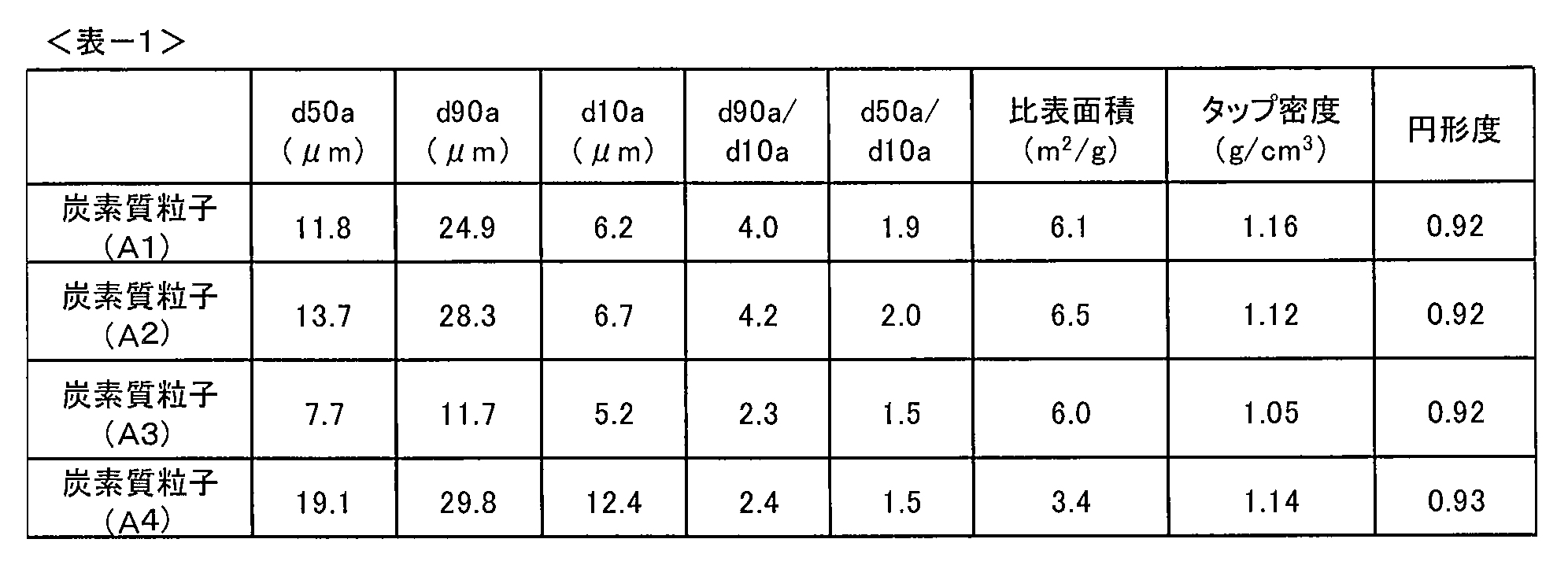
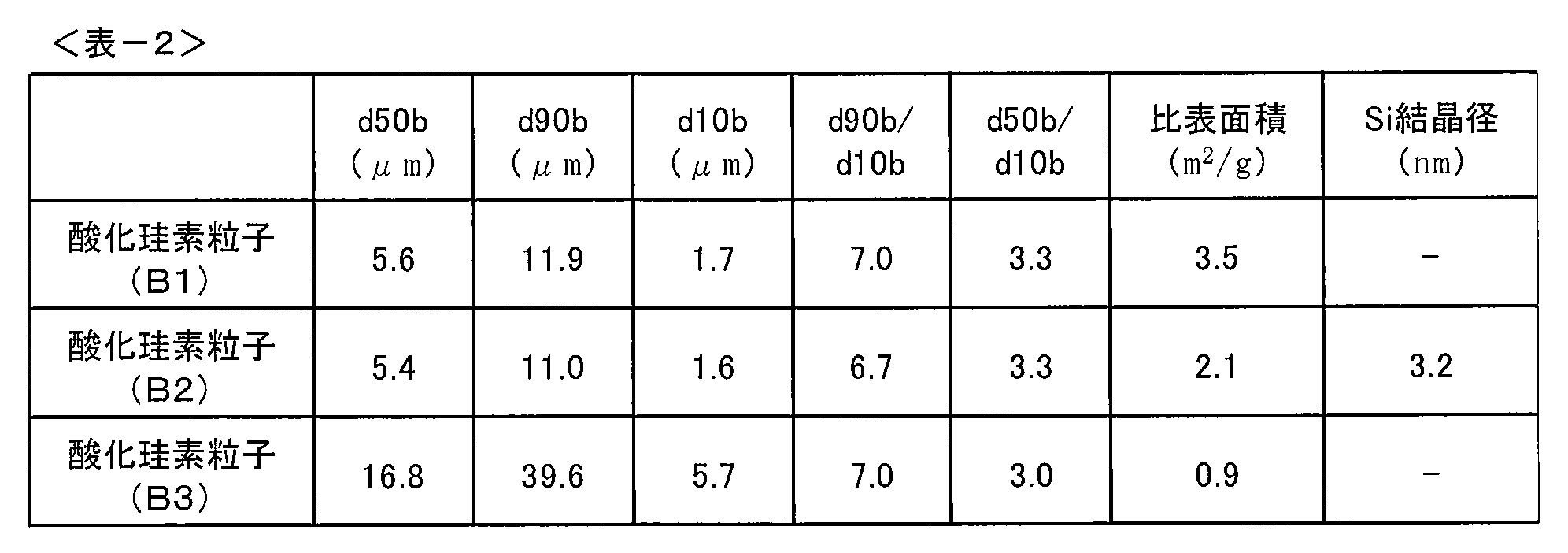

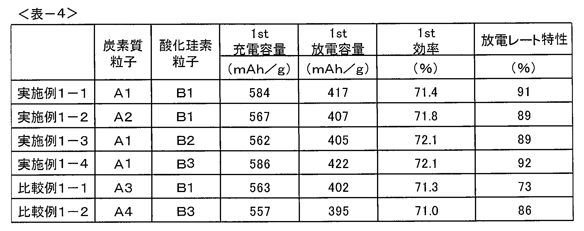
1)実施例1-1及び1-2と、比較例1-1との対比により、酸化珪素粒子(B1)と混合する炭素質粒子を、炭素質粒子(A3)とした場合(R1=2.5、R2=1.6)よりも、炭素質粒子(A1)とした場合(R1=4.3、R2=2.1)又は(A2)とした場合(R1=4.8、R2=2.2)の方が、充放電容量、効率及び放電レート特性、特に放電レート特性に優れることがわかる。
2)実施例1-4と比較例1-2との対比により、酸化珪素粒子(B3)と混合する炭素質粒子を、炭素質粒子(A4)とした場合(R1=2.6、R2=1.6)よりも、炭素質粒子(A1)とした場合(R1=4.3、R2=2.0)の方が、充放電容量、効率及び放電レート特性に優れることがわかる。
炭素質粒子と酸化珪素粒子の混合物(重量比9:1)97.5重量%と、バインダーとしてカルボキシメチルセルロース(CMC)1重量%及びスチレン・ブタジエンゴム(SBR)48重量%水性ディスパージョン3.1重量%とを、ハイブリダイズミキサーにて混練し、スラリーとした。このスラリーを厚さ20μmの銅箔上にブレード法で、目付け4~5mg/cm2となるように塗布し、乾燥させた。
乾燥アルゴン雰囲気下、エチレンカーボネート、エチルメチルカーボネートの混合物(体積比3:7)に、乾燥したLiPF6を1.0mol/Lの割合となるように溶解し、基準電解液とした。基準電解液にジフルオロリン酸リチウムを0.50質量%となるように混合し、電解液(E2)を得た。
上記方法で作製した電極シートを評価用負極とし、リチウム金属箔を直径15mmの円板状に打ち抜き対極とした。両極の間には、上述の電解液を含浸させたセパレータ(多孔性ポリエチレンフィルム製)を置き、コイン型の性能評価用電池IIをそれぞれ作製した。
前述の方法で作製した非水系二次電池(コイン型電池)を用いて、下記の測定方法で効率改善度を測定した。
0.05Cの電流密度でリチウム対極に対して5mVまで充電し、さらに5mVの一定電圧で電流密度が0.005Cになるまで充電し、負極中にリチウムをドープした後、0.1Cの電流密度でリチウム対極に対して1.5Vまで放電を行った。
ここで得られた1サイクル目の放電容量(mAh)を充電容量(mAh)で割り返した値を効率とした。電解液E2及びE3を用いた場合の効率から基準電解液を用いた場合の効率を引いた値を効率改善度とした。
炭素質粒子として炭素質粒子(A1)、酸化珪素粒子として酸化珪素粒子(B1)を用いて、基準電解液に対する電解液E2の効率改善度を測定した。なお、後述する実施例および比較例の効率改善度は、本測定値を100とした場合の相対値として算出した。その結果を表-5に示す。
炭素質粒子として炭素質粒子(A2)、酸化珪素粒子として酸化珪素粒子(B1)を用いて、基準電解液に対する電解液E2の効率改善度を測定した。その結果を表-5に示す。
炭素質粒子として炭素質粒子(A1)、酸化珪素粒子として酸化珪素粒子(B2)を用いて、基準電解液に対する電解液E2の効率改善度を測定した。その結果を表-5に示す。
炭素質粒子として炭素質粒子(A1)、酸化珪素粒子として酸化珪素粒子(B2)を用いて、基準電解液に対する電解液E3の効率改善度を測定した。その結果を表-5に示す。
炭素質粒子として炭素質粒子(A3)、酸化珪素粒子として酸化珪素粒子(B1)を用いて、基準電解液に対する電解液E2の効率改善度を測定した。その結果を表-5に示す。
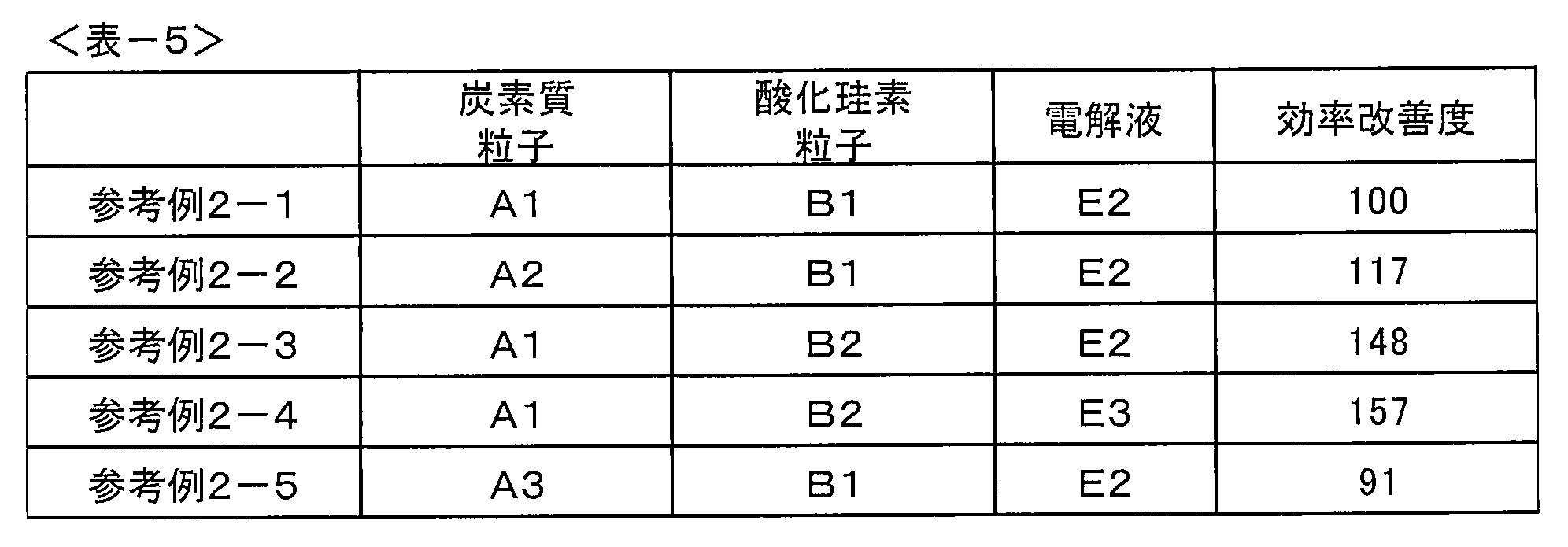
1)参考例2-1と参考例2-2の対比により、炭素質粒子(A1)を炭素質粒子(A2)に変更することで充放電効率の改善効果が向上したことがわかる。
2)参考例2-3と参考例2-4の対比により、電解液中にジフルオロリン酸リチウム以外の成分を含有しても充放電効率の改善効果が得られることがわかる。
Claims (16)
- 炭素質粒子(A)と酸化珪素粒子(B)を含み、下記a)~c)を満たす非水系二次電池用負極材。
a)平均粒子径(小粒子側から50%積算部の粒子径)(d50)が3μm以上30μm以下、小粒子側から10%積算部の粒子径(d10)が0.1μm以上10μm以下
b)小粒子側から90%積算部の粒子径(d90)とd10の比(R1=d90/d10)が3以上20以下
c)d50とd10の比(R2=d50/d10)が1.7以上5以下 - 酸化珪素粒子(B)の平均粒子径(小粒子側から50%積算部の粒子径)(d50b)と炭素質粒子(A)の平均粒子径(小粒子側から50%積算部の粒子径)(d50a)との比(R3=d50b/d50a)が0.01以上1以下である、請求項1に記載の非水系二次電池用負極材。
- 酸化珪素粒子(B)のd50bと炭素質粒子(A)の小粒子側から10%積算部の粒子径(d10a)との比(R4=d50b/d10a)が0.01以上2以下である、請求項1又は2に記載の非水系二次電池用負極材。
- 炭素質粒子(A)のd50aが5μm以上30μm以下で、小粒子側から90%積算部の粒子径(d90a)と小粒子側から10%積算部の粒子径(d10a)の比(R1a=d90a/d10a)が3以上10以下である、請求項1乃至3のいずれか1項に記載の非水系二次電池用負極材。
- 酸化珪素粒子(B)のd50bが0.1μm以上20μm以下で、小粒子側から90%積算部の粒子径(d90b)と小粒子側から10%積算部の粒子径(d10b)の比(R1b=d90b/d10b)が3以上15以下である、請求項1乃至4のいずれか1項に記載の非水系二次電池用負極材。
- 酸化珪素粒子(B)の小粒子側から10%積算部の粒子径(d10b)が0.001μm以上6μm以下である、請求項1乃至5のいずれか1項に記載の非水系二次電池用負極材。
- 炭素質粒子(A)と酸化珪素粒子(B)を[炭素質粒子(A)の重量]:[酸化珪素粒子(B)の重量]=30:70~99:1で含む、請求項1乃至6のいずれか1項に記載の非水系二次電池用負極材。
- 炭素質粒子(A)のフロー式粒子像分析より求められる円形度が0.88以上である、請求項1乃至7のいずれか1項に記載の非水系二次電池用負極材。
- 炭素質粒子(A)が球形化黒鉛を含む、請求項1乃至8のいずれか1項に記載の非水系二次電池用負極材。
- 酸化珪素粒子(B)における珪素原子数(MSi)に対する酸素原子数(MO)の比(MO/MSi)が0.5~1.6である、請求項1乃至9のいずれか1項に記載の非水系二次電池用負極材。
- 酸化珪素粒子(B)がゼロ価の珪素原子を含む、請求項1乃至10のいずれか1項に記載の非水系二次電池用負極材。
- 酸化珪素粒子(B)中に珪素の微結晶を含む、請求項1乃至11のいずれか1項に記載の非水系二次電池用負極材。
- 集電体と、該集電体上に形成された活物質層とを備える非水系二次電池用負極であって、該活物質層が請求項1乃至12のいずれか1項に記載の非水系二次電池用負極材を含有する、非水系二次電池用負極。
- 正極及び負極、並びに電解質を備える非水系二次電池であって、該負極が請求項13に記載の非水系二次電池用負極である、非水系二次電池。
- 前記電解質が非水溶媒中に含まれる電解液である、請求項14に記載の非水系二次電池。
- 前記電解液中にジフルオロリン酸リチウムを含み、その含有量が電解液全体に対して0.01重量%以上2重量%以下である、請求項15に記載の非水系二次電池。
Priority Applications (7)
| Application Number | Priority Date | Filing Date | Title |
|---|---|---|---|
| CN202211130303.6A CN115483391B (zh) | 2016-11-22 | 2017-11-22 | 非水二次电池用负极材料、非水二次电池用负极及非水二次电池 |
| JP2018552952A JP7099325B2 (ja) | 2016-11-22 | 2017-11-22 | 非水系二次電池用負極材、非水系二次電池用負極及び非水系二次電池 |
| CN201780072248.0A CN110024189B (zh) | 2016-11-22 | 2017-11-22 | 非水二次电池用负极材料、非水二次电池用负极及非水二次电池 |
| KR1020197015064A KR102412700B1 (ko) | 2016-11-22 | 2017-11-22 | 비수계 2 차 전지용 부극재, 비수계 2 차 전지용 부극 및 비수계 2 차 전지 |
| US16/419,744 US11961996B2 (en) | 2016-11-22 | 2019-05-22 | Negative electrode material for nonaqueous secondary batteries, negative electrode for nonaqueous secondary batteries, and nonaqueous secondary battery |
| US18/602,456 US20240258500A1 (en) | 2016-11-22 | 2024-03-12 | Negative electrode material for nonaqueous secondary batteries, negative electrode for nonaqueous secondary batteries, and nonaqueous secondary battery |
| US19/417,652 US20260112610A1 (en) | 2016-11-22 | 2025-12-12 | Negative electrode material for nonaqueous secondary batteries, negative electrode for nonaqueous secondary batteries, and nonaqueous secondary battery |
Applications Claiming Priority (2)
| Application Number | Priority Date | Filing Date | Title |
|---|---|---|---|
| JP2016227259 | 2016-11-22 | ||
| JP2016-227259 | 2016-11-22 |
Related Child Applications (1)
| Application Number | Title | Priority Date | Filing Date |
|---|---|---|---|
| US16/419,744 Continuation US11961996B2 (en) | 2016-11-22 | 2019-05-22 | Negative electrode material for nonaqueous secondary batteries, negative electrode for nonaqueous secondary batteries, and nonaqueous secondary battery |
Publications (1)
| Publication Number | Publication Date |
|---|---|
| WO2018097212A1 true WO2018097212A1 (ja) | 2018-05-31 |
Family
ID=62195026
Family Applications (1)
| Application Number | Title | Priority Date | Filing Date |
|---|---|---|---|
| PCT/JP2017/042108 Ceased WO2018097212A1 (ja) | 2016-11-22 | 2017-11-22 | 非水系二次電池用負極材、非水系二次電池用負極及び非水系二次電池 |
Country Status (5)
| Country | Link |
|---|---|
| US (3) | US11961996B2 (ja) |
| JP (1) | JP7099325B2 (ja) |
| KR (1) | KR102412700B1 (ja) |
| CN (2) | CN110024189B (ja) |
| WO (1) | WO2018097212A1 (ja) |
Cited By (17)
| Publication number | Priority date | Publication date | Assignee | Title |
|---|---|---|---|---|
| WO2020107927A1 (zh) * | 2018-11-29 | 2020-06-04 | 贝特瑞新材料集团股份有限公司 | 天然石墨及由其制备得到的改性天然石墨材料、制备方法和应用 |
| WO2020130465A1 (ko) * | 2018-12-17 | 2020-06-25 | 주식회사 엘지화학 | 이차전지용 음극 활물질, 이를 포함하는 음극 및 이의 제조방법 |
| WO2020135110A1 (zh) * | 2018-12-29 | 2020-07-02 | 宁德时代新能源科技股份有限公司 | 负极活性材料、电池及装置 |
| JP2020119855A (ja) * | 2019-01-28 | 2020-08-06 | 三菱ケミカル株式会社 | 非水系電解液電池 |
| EP3754761A4 (en) * | 2018-10-24 | 2021-05-19 | Lg Chem, Ltd. | ANODE WITH GRAPHITE AND SILICONE BASED MATERIAL WITH DIFFERENT DIAMETERS AND LITHIUM SECONDARY BATTERY WITH IT |
| TWI747740B (zh) * | 2020-02-21 | 2021-11-21 | 日商杰富意化學股份有限公司 | 球狀化石墨、經被覆之球狀化石墨、鋰離子二次電池用負極及鋰二次電池 |
| JP2022513678A (ja) * | 2019-01-18 | 2022-02-09 | エルジー エナジー ソリューション リミテッド | 二次電池用負極活物質の製造方法、二次電池用負極及びこれを含むリチウム二次電池 |
| EP3869586A4 (en) * | 2018-10-17 | 2022-07-13 | Murata Manufacturing Co., Ltd. | NEGATIVE ELECTRODE FOR SECONDARY LITHIUM-ION BATTERY AND SECONDARY LITHIUM-ION BATTERY |
| EP4024512A4 (en) * | 2019-10-04 | 2022-11-02 | Lg Energy Solution, Ltd. | CARBON-BASED GLOBULAR ACTIVE ANODE MATERIAL, PROCESS FOR ITS MANUFACTURE, AND ANOD AND LITHIUM SECONDARY BATTERY WITH THEM |
| JPWO2023037841A1 (ja) * | 2021-09-10 | 2023-03-16 | ||
| US12095037B2 (en) | 2018-07-26 | 2024-09-17 | Mitsui Chemicals, Inc. | Non-aqueous electrolyte solution for battery and lithium secondary battery |
| WO2024202300A1 (ja) | 2023-03-29 | 2024-10-03 | 株式会社Aescジャパン | 非水電解質二次電池用負極およびそれを用いた非水電解質二次電池 |
| WO2024202302A1 (ja) | 2023-03-29 | 2024-10-03 | 株式会社Aescジャパン | 非水電解質二次電池用負極およびそれを用いた非水電解質二次電池 |
| EP4535453A1 (en) * | 2018-10-24 | 2025-04-09 | LG Energy Solution, Ltd. | Anode including graphite and silicon-based material having different diameters and lithium secondary battery including the same |
| WO2025205672A1 (ja) * | 2024-03-29 | 2025-10-02 | 株式会社Aescジャパン | 負極活物質、負極、リチウムイオン二次電池およびリチウムイオン二次電池モジュール |
| WO2025205673A1 (ja) * | 2024-03-29 | 2025-10-02 | 株式会社Aescジャパン | 負極活物質、負極、リチウムイオン二次電池およびリチウムイオン二次電池モジュール |
| WO2026142013A1 (ko) * | 2024-12-24 | 2026-07-02 | 주식회사 엘지에너지솔루션 | 리튬 이차 전지 |
Families Citing this family (16)
| Publication number | Priority date | Publication date | Assignee | Title |
|---|---|---|---|---|
| EP4044289A4 (en) * | 2019-10-10 | 2024-10-02 | Kuraray Co., Ltd. | CARBON MATERIAL FOR ELECTROCHEMICAL DEVICE, PRODUCTION METHOD THEREOF, NEGATIVE ELECTRODE FOR ELECTROCHEMICAL DEVICE, AND ELECTROCHEMICAL DEVICE |
| WO2021092868A1 (zh) | 2019-11-14 | 2021-05-20 | 宁德新能源科技有限公司 | 负极材料及包含其的电化学装置和电子装置 |
| CN110911636B (zh) * | 2019-11-14 | 2021-08-31 | 宁德新能源科技有限公司 | 负极材料及包含其的电化学装置和电子装置 |
| JP7265636B2 (ja) * | 2019-11-28 | 2023-04-26 | 寧徳新能源科技有限公司 | 負極材料、並びに、それを含む電気化学装置及び電子装置 |
| US12330946B2 (en) | 2020-02-19 | 2025-06-17 | Jfe Chemical Corporation | Carbon material for negative electrode of lithium ion secondary battery and method of producing the same, and negative electrode and lithium ion secondary battery using the carbon material |
| WO2022140902A1 (zh) * | 2020-12-28 | 2022-07-07 | 宁德时代新能源科技股份有限公司 | 负极极片及其制备方法、二次电池、电池模块、电池包和装置 |
| KR102852650B1 (ko) * | 2021-01-29 | 2025-08-29 | 주식회사 엘지에너지솔루션 | 음극 및 이를 포함하는 이차전지 |
| JP7286697B2 (ja) * | 2021-03-17 | 2023-06-05 | プライムプラネットエナジー&ソリューションズ株式会社 | リチウムイオン二次電池の製造方法 |
| EP4148832A4 (en) * | 2021-04-05 | 2023-09-06 | Resonac Corporation | NEGATIVE ELECTRODE MATERIAL FOR LITHIUM-ION SECONDARY BATTERY, NEGATIVE ELECTRODE FOR LITHIUM-ION SECONDARY BATTERY AND LITHIUM-ION SECONDARY BATTERY |
| WO2022264384A1 (ja) | 2021-06-17 | 2022-12-22 | 昭和電工マテリアルズ株式会社 | リチウムイオン二次電池用負極材、リチウムイオン二次電池用負極及びリチウムイオン二次電池 |
| KR20220169155A (ko) * | 2021-06-18 | 2022-12-27 | 에스케이온 주식회사 | 음극 활물질, 이를 포함하는 음극용 조성물 및 이로부터 제조된 이차 전지 |
| CN115863617B (zh) * | 2022-12-12 | 2026-04-14 | 瑞浦兰钧能源股份有限公司 | 一种硅基电池负极材料及二次电池 |
| JP7731924B2 (ja) * | 2023-02-01 | 2025-09-01 | プライムプラネットエナジー&ソリューションズ株式会社 | 非水電解液二次電池 |
| CN119092701A (zh) * | 2023-10-31 | 2024-12-06 | 贝特瑞新材料集团股份有限公司 | 负极材料及其制备方法、电池 |
| CN121439769A (zh) * | 2023-10-31 | 2026-01-30 | 贝特瑞新材料集团股份有限公司 | 负极材料及负极极片、锂离子电池 |
| US12351462B1 (en) | 2024-10-25 | 2025-07-08 | Urbix, Inc. | Graphite shaping and coating devices, systems, and methods |
Citations (8)
| Publication number | Priority date | Publication date | Assignee | Title |
|---|---|---|---|---|
| JP2013101921A (ja) * | 2011-10-12 | 2013-05-23 | Toyota Industries Corp | リチウムイオン二次電池用負極及びその負極を用いたリチウムイオン二次電池 |
| JP2013200984A (ja) * | 2012-03-23 | 2013-10-03 | Mitsubishi Chemicals Corp | 非水系二次電池用負極材、非水系二次電池用負極及び非水系二次電池 |
| JP2013200983A (ja) * | 2012-03-23 | 2013-10-03 | Mitsubishi Chemicals Corp | 非水系二次電池用負極材、非水系二次電池用負極及び非水系二次電池 |
| JP2015106437A (ja) * | 2013-11-28 | 2015-06-08 | 株式会社デンソー | 非水電解質電池 |
| JP2015191853A (ja) * | 2014-03-28 | 2015-11-02 | トヨタ自動車株式会社 | リチウムイオン二次電池の製造方法 |
| JP2016062810A (ja) * | 2014-09-19 | 2016-04-25 | 株式会社東芝 | 非水電解質二次電池用負極およびそれを備えた非水電解質二次電池 |
| JP2016103337A (ja) * | 2014-11-27 | 2016-06-02 | 株式会社日立製作所 | リチウムイオン二次電池及びリチウムイオン二次電池の製造方法 |
| WO2017155021A1 (ja) * | 2016-03-10 | 2017-09-14 | 日本電気株式会社 | リチウムイオン二次電池 |
Family Cites Families (16)
| Publication number | Priority date | Publication date | Assignee | Title |
|---|---|---|---|---|
| JP5555978B2 (ja) * | 2008-02-28 | 2014-07-23 | 信越化学工業株式会社 | 非水電解質二次電池用負極活物質、及びそれを用いた非水電解質二次電池 |
| JP5458689B2 (ja) | 2008-06-25 | 2014-04-02 | 三菱化学株式会社 | 非水系二次電池用複合黒鉛粒子、それを含有する負極材料、負極及び非水系二次電池 |
| JP5659696B2 (ja) * | 2009-12-24 | 2015-01-28 | ソニー株式会社 | リチウムイオン二次電池、リチウムイオン二次電池用負極、電動工具、電気自動車および電力貯蔵システム |
| EP2571084A4 (en) * | 2010-05-11 | 2013-10-02 | Route Jj Co Ltd | ANODEACTIVE MATERIAL FOR A LITHIUM SUBSTANCE BATTERY, METHOD OF MANUFACTURING THEREOF AND LITHIUM SUBSTITUTING BATTERY THEREWITH |
| WO2013054500A1 (ja) | 2011-10-14 | 2013-04-18 | 株式会社豊田自動織機 | 蓄電装置用負極材料、蓄電装置用負極、蓄電装置ならびに車両 |
| JP6334195B2 (ja) * | 2013-02-21 | 2018-05-30 | Connexx Systems株式会社 | リチウム二次電池用複合活物質およびその製造方法 |
| CN105050952A (zh) * | 2013-03-26 | 2015-11-11 | 三菱化学株式会社 | 碳材料、使用该碳材料的非水系二次电池 |
| PL2989671T3 (pl) | 2013-04-27 | 2019-12-31 | Shanghai Jiaotong University | MATERIAŁ KOMPOZYTOWY SiOx/Si/C I SPOSÓB JEGO WYTWARZANIA, I ANODA DO AKUMULATORA LITOWO-JONOWEGO ZAWIERAJĄCA WSPOMNIANY MATERIAŁ KOMPOZYTOWY |
| EP2824750B1 (en) * | 2013-07-08 | 2019-01-30 | Samsung SDI Co., Ltd. | Silicon-containing compound used in electrolytes for lithium secondary batteries |
| JP6508870B2 (ja) * | 2013-08-14 | 2019-05-08 | 東ソー株式会社 | リチウム二次電池用複合活物質およびその製造方法 |
| JP6359836B2 (ja) * | 2014-02-07 | 2018-07-18 | 信越化学工業株式会社 | 非水電解質二次電池用負極材、非水電解質二次電池用負極及びその製造方法並びに非水電解質二次電池 |
| CN104916841A (zh) * | 2014-03-13 | 2015-09-16 | 新日铁住金化学株式会社 | 锂离子二次电池用负极活性物质及使用其的锂离子二次电池负极以及锂离子二次电池 |
| CN107112536B (zh) * | 2015-01-16 | 2021-11-16 | 三菱化学株式会社 | 碳材料及使用了碳材料的非水系二次电池 |
| CN104638237B (zh) * | 2015-01-20 | 2018-03-13 | 深圳市贝特瑞新能源材料股份有限公司 | 一种锂离子电池氧化亚硅复合材料、制备方法及其用途 |
| JP6794982B2 (ja) | 2015-03-24 | 2020-12-02 | 日本電気株式会社 | リチウムイオン二次電池 |
| TW201826607A (zh) * | 2016-09-08 | 2018-07-16 | 日商麥克賽爾控股股份有限公司 | 鋰離子二次電池及其製造方法 |
-
2017
- 2017-11-22 JP JP2018552952A patent/JP7099325B2/ja active Active
- 2017-11-22 CN CN201780072248.0A patent/CN110024189B/zh active Active
- 2017-11-22 CN CN202211130303.6A patent/CN115483391B/zh active Active
- 2017-11-22 KR KR1020197015064A patent/KR102412700B1/ko active Active
- 2017-11-22 WO PCT/JP2017/042108 patent/WO2018097212A1/ja not_active Ceased
-
2019
- 2019-05-22 US US16/419,744 patent/US11961996B2/en active Active
-
2024
- 2024-03-12 US US18/602,456 patent/US20240258500A1/en not_active Abandoned
-
2025
- 2025-12-12 US US19/417,652 patent/US20260112610A1/en active Pending
Patent Citations (8)
| Publication number | Priority date | Publication date | Assignee | Title |
|---|---|---|---|---|
| JP2013101921A (ja) * | 2011-10-12 | 2013-05-23 | Toyota Industries Corp | リチウムイオン二次電池用負極及びその負極を用いたリチウムイオン二次電池 |
| JP2013200984A (ja) * | 2012-03-23 | 2013-10-03 | Mitsubishi Chemicals Corp | 非水系二次電池用負極材、非水系二次電池用負極及び非水系二次電池 |
| JP2013200983A (ja) * | 2012-03-23 | 2013-10-03 | Mitsubishi Chemicals Corp | 非水系二次電池用負極材、非水系二次電池用負極及び非水系二次電池 |
| JP2015106437A (ja) * | 2013-11-28 | 2015-06-08 | 株式会社デンソー | 非水電解質電池 |
| JP2015191853A (ja) * | 2014-03-28 | 2015-11-02 | トヨタ自動車株式会社 | リチウムイオン二次電池の製造方法 |
| JP2016062810A (ja) * | 2014-09-19 | 2016-04-25 | 株式会社東芝 | 非水電解質二次電池用負極およびそれを備えた非水電解質二次電池 |
| JP2016103337A (ja) * | 2014-11-27 | 2016-06-02 | 株式会社日立製作所 | リチウムイオン二次電池及びリチウムイオン二次電池の製造方法 |
| WO2017155021A1 (ja) * | 2016-03-10 | 2017-09-14 | 日本電気株式会社 | リチウムイオン二次電池 |
Cited By (31)
| Publication number | Priority date | Publication date | Assignee | Title |
|---|---|---|---|---|
| US12095037B2 (en) | 2018-07-26 | 2024-09-17 | Mitsui Chemicals, Inc. | Non-aqueous electrolyte solution for battery and lithium secondary battery |
| EP3869586A4 (en) * | 2018-10-17 | 2022-07-13 | Murata Manufacturing Co., Ltd. | NEGATIVE ELECTRODE FOR SECONDARY LITHIUM-ION BATTERY AND SECONDARY LITHIUM-ION BATTERY |
| US11929490B2 (en) | 2018-10-24 | 2024-03-12 | Lg Energy Solution, Ltd. | Anode including graphite and silicon-based material having different diameters and lithium secondary battery including the same |
| EP3754761A4 (en) * | 2018-10-24 | 2021-05-19 | Lg Chem, Ltd. | ANODE WITH GRAPHITE AND SILICONE BASED MATERIAL WITH DIFFERENT DIAMETERS AND LITHIUM SECONDARY BATTERY WITH IT |
| EP4535453A1 (en) * | 2018-10-24 | 2025-04-09 | LG Energy Solution, Ltd. | Anode including graphite and silicon-based material having different diameters and lithium secondary battery including the same |
| EP3780181A4 (en) * | 2018-11-29 | 2022-01-26 | Btr New Material Group Co., Ltd. | NATURAL GRAPHITE, MODIFIED NATURAL GRAPHITE MATERIAL PREPARED THEREOF, PREPARATION METHOD AND APPLICATIONS |
| WO2020107927A1 (zh) * | 2018-11-29 | 2020-06-04 | 贝特瑞新材料集团股份有限公司 | 天然石墨及由其制备得到的改性天然石墨材料、制备方法和应用 |
| JP7105910B2 (ja) | 2018-12-17 | 2022-07-25 | エルジー エナジー ソリューション リミテッド | 二次電池用負極活物質、それを含む負極及びその製造方法 |
| JP2021518042A (ja) * | 2018-12-17 | 2021-07-29 | エルジー・ケム・リミテッド | 二次電池用負極活物質、それを含む負極及びその製造方法 |
| US11862799B2 (en) | 2018-12-17 | 2024-01-02 | Lg Energy Solution, Ltd. | Anode active material for secondary battery, anode comprising same, and method for manufacturing same |
| WO2020130465A1 (ko) * | 2018-12-17 | 2020-06-25 | 주식회사 엘지화학 | 이차전지용 음극 활물질, 이를 포함하는 음극 및 이의 제조방법 |
| WO2020135110A1 (zh) * | 2018-12-29 | 2020-07-02 | 宁德时代新能源科技股份有限公司 | 负极活性材料、电池及装置 |
| US12401024B2 (en) | 2018-12-29 | 2025-08-26 | Contemporary Amperex Technology (Hong Kong) Limited | Negative electrode active material, negative electrode plate and battery |
| JP2022513678A (ja) * | 2019-01-18 | 2022-02-09 | エルジー エナジー ソリューション リミテッド | 二次電池用負極活物質の製造方法、二次電池用負極及びこれを含むリチウム二次電池 |
| JP7143006B2 (ja) | 2019-01-18 | 2022-09-28 | エルジー エナジー ソリューション リミテッド | 二次電池用負極活物質の製造方法、二次電池用負極及びこれを含むリチウム二次電池 |
| US12087934B2 (en) | 2019-01-18 | 2024-09-10 | Lg Energy Solution, Ltd. | Method of producing negative electrode active material for secondary battery, negative electrode for secondary battery, and lithium secondary battery including the same |
| JP2020119855A (ja) * | 2019-01-28 | 2020-08-06 | 三菱ケミカル株式会社 | 非水系電解液電池 |
| EP4024512A4 (en) * | 2019-10-04 | 2022-11-02 | Lg Energy Solution, Ltd. | CARBON-BASED GLOBULAR ACTIVE ANODE MATERIAL, PROCESS FOR ITS MANUFACTURE, AND ANOD AND LITHIUM SECONDARY BATTERY WITH THEM |
| US12476251B2 (en) | 2019-10-04 | 2025-11-18 | Lg Energy Solution, Ltd. | Globular carbon-based anode active material, method for manufacturing same, and anode and lithium secondary battery comprising same |
| TWI747740B (zh) * | 2020-02-21 | 2021-11-21 | 日商杰富意化學股份有限公司 | 球狀化石墨、經被覆之球狀化石墨、鋰離子二次電池用負極及鋰二次電池 |
| WO2023037841A1 (ja) * | 2021-09-10 | 2023-03-16 | 三菱ケミカル株式会社 | 炭素材、炭素材の製造方法、球状炭素材の製造方法、複合炭素材の製造方法及び二次電池の製造方法 |
| EP4401172A4 (en) * | 2021-09-10 | 2025-03-19 | Mitsubishi Chemical Corporation | Carbon material, method for producing carbon material, method for producing spherical carbon material, method for producing composite carbon material, and method for producing secondary battery |
| JPWO2023037841A1 (ja) * | 2021-09-10 | 2023-03-16 | ||
| JP7779321B2 (ja) | 2021-09-10 | 2025-12-03 | 三菱ケミカル株式会社 | 炭素材、炭素材の製造方法、球状炭素材の製造方法、複合炭素材の製造方法及び二次電池の製造方法 |
| WO2024202302A1 (ja) | 2023-03-29 | 2024-10-03 | 株式会社Aescジャパン | 非水電解質二次電池用負極およびそれを用いた非水電解質二次電池 |
| WO2024202300A1 (ja) | 2023-03-29 | 2024-10-03 | 株式会社Aescジャパン | 非水電解質二次電池用負極およびそれを用いた非水電解質二次電池 |
| EP4693461A1 (en) | 2023-03-29 | 2026-02-11 | AESC Japan Ltd. | Negative electrode for nonaqueous electrolyte secondary battery, and nonaqueous electrolyte secondary battery using same |
| EP4693459A1 (en) | 2023-03-29 | 2026-02-11 | AESC Japan Ltd. | Negative electrode for nonaqueous electrolyte secondary battery, and nonaqueous electrolyte secondary battery using same |
| WO2025205672A1 (ja) * | 2024-03-29 | 2025-10-02 | 株式会社Aescジャパン | 負極活物質、負極、リチウムイオン二次電池およびリチウムイオン二次電池モジュール |
| WO2025205673A1 (ja) * | 2024-03-29 | 2025-10-02 | 株式会社Aescジャパン | 負極活物質、負極、リチウムイオン二次電池およびリチウムイオン二次電池モジュール |
| WO2026142013A1 (ko) * | 2024-12-24 | 2026-07-02 | 주식회사 엘지에너지솔루션 | 리튬 이차 전지 |
Also Published As
| Publication number | Publication date |
|---|---|
| KR102412700B1 (ko) | 2022-06-23 |
| CN115483391A (zh) | 2022-12-16 |
| JP7099325B2 (ja) | 2022-07-12 |
| CN110024189A (zh) | 2019-07-16 |
| CN115483391B (zh) | 2026-06-16 |
| US20260112610A1 (en) | 2026-04-23 |
| KR20190077446A (ko) | 2019-07-03 |
| US20240258500A1 (en) | 2024-08-01 |
| US20190273248A1 (en) | 2019-09-05 |
| JPWO2018097212A1 (ja) | 2019-10-17 |
| US11961996B2 (en) | 2024-04-16 |
| CN110024189B (zh) | 2022-08-30 |
Similar Documents
| Publication | Publication Date | Title |
|---|---|---|
| JP7099325B2 (ja) | 非水系二次電池用負極材、非水系二次電池用負極及び非水系二次電池 | |
| JP7192499B2 (ja) | 非水系二次電池用負極材、非水系二次電池用負極及び非水系二次電池 | |
| KR101970023B1 (ko) | 비수계 이차 전지용 탄소재, 그 탄소재를 사용한 부극 및 비수계 이차 전지 | |
| JP6977504B2 (ja) | 非水系二次電池用負極材、非水系二次電池用負極及び非水系二次電池 | |
| JP6981203B2 (ja) | 非水系二次電池用負極材、非水系二次電池用負極及び非水系二次電池 | |
| JP6060506B2 (ja) | 非水系二次電池用負極材、非水系二次電池用負極及び非水系二次電池 | |
| JP5994319B2 (ja) | 非水系二次電池用複合黒鉛粒子の製造方法及びその製造方法で得られた複合黒鉛粒子、負極並びに非水系二次電池 | |
| JP2012216545A (ja) | 非水系二次電池用黒鉛粒子及びその製造方法、負極並びに非水系二次電池 | |
| JP7127275B2 (ja) | 非水系二次電池用負極材、非水系二次電池用負極及び非水系二次電池 | |
| JP7334735B2 (ja) | 非水系二次電池用負極材、非水系二次電池用負極及び非水系二次電池 | |
| JP2014060124A (ja) | 非水系二次電池用負極材、非水系二次電池用負極及び非水系二次電池 | |
| WO2019189800A1 (ja) | 非水系二次電池用負極材、非水系二次電池用負極及び非水系二次電池 | |
| JP2016186912A (ja) | 非水系二次電池用複合炭素材、及び、非水系二次電池 | |
| JP6379565B2 (ja) | 非水系二次電池負極用炭素材、及び、非水系二次電池 | |
| JP2022095866A (ja) | 非水系二次電池用負極材、非水系二次電池用負極及び非水系二次電池 | |
| JP7077721B2 (ja) | 非水系二次電池用負極材、非水系二次電池用負極及び非水系二次電池 | |
| JP2017126425A (ja) | 非水系二次電池用炭素材、及び、リチウムイオン二次電池 | |
| JP2016189319A (ja) | 炭素材、及び、非水系二次電池 | |
| JP2015185444A (ja) | 非水系二次電池負極用炭素材、及び、非水系二次電池 | |
| JP2014067642A (ja) | 非水系二次電池用複合炭素材及びその製造方法、負極並びに非水系二次電池 | |
| JP2014165079A (ja) | 非水系二次電池用炭素材及びその製造方法、それを用いた負極及び非水系二次電池 |
Legal Events
| Date | Code | Title | Description |
|---|---|---|---|
| 121 | Ep: the epo has been informed by wipo that ep was designated in this application |
Ref document number: 17874711 Country of ref document: EP Kind code of ref document: A1 |
|
| ENP | Entry into the national phase |
Ref document number: 2018552952 Country of ref document: JP Kind code of ref document: A |
|
| NENP | Non-entry into the national phase |
Ref country code: DE |
|
| ENP | Entry into the national phase |
Ref document number: 20197015064 Country of ref document: KR Kind code of ref document: A |
|
| 122 | Ep: pct application non-entry in european phase |
Ref document number: 17874711 Country of ref document: EP Kind code of ref document: A1 |