WO2017175557A1 - トルクコンバータ - Google Patents
トルクコンバータ Download PDFInfo
- Publication number
- WO2017175557A1 WO2017175557A1 PCT/JP2017/010597 JP2017010597W WO2017175557A1 WO 2017175557 A1 WO2017175557 A1 WO 2017175557A1 JP 2017010597 W JP2017010597 W JP 2017010597W WO 2017175557 A1 WO2017175557 A1 WO 2017175557A1
- Authority
- WO
- WIPO (PCT)
- Prior art keywords
- spring
- damper
- holding
- output shaft
- clutch piston
- Prior art date
Links
Images


Classifications
-
- F—MECHANICAL ENGINEERING; LIGHTING; HEATING; WEAPONS; BLASTING
- F16—ENGINEERING ELEMENTS AND UNITS; GENERAL MEASURES FOR PRODUCING AND MAINTAINING EFFECTIVE FUNCTIONING OF MACHINES OR INSTALLATIONS; THERMAL INSULATION IN GENERAL
- F16F—SPRINGS; SHOCK-ABSORBERS; MEANS FOR DAMPING VIBRATION
- F16F15/00—Suppression of vibrations in systems; Means or arrangements for avoiding or reducing out-of-balance forces, e.g. due to motion
- F16F15/10—Suppression of vibrations in rotating systems by making use of members moving with the system
- F16F15/12—Suppression of vibrations in rotating systems by making use of members moving with the system using elastic members or friction-damping members, e.g. between a rotating shaft and a gyratory mass mounted thereon
- F16F15/121—Suppression of vibrations in rotating systems by making use of members moving with the system using elastic members or friction-damping members, e.g. between a rotating shaft and a gyratory mass mounted thereon using springs as elastic members, e.g. metallic springs
- F16F15/123—Wound springs
- F16F15/1232—Wound springs characterised by the spring mounting
- F16F15/1234—Additional guiding means for springs, e.g. for support along the body of springs that extend circumferentially over a significant length
-
- F—MECHANICAL ENGINEERING; LIGHTING; HEATING; WEAPONS; BLASTING
- F16—ENGINEERING ELEMENTS AND UNITS; GENERAL MEASURES FOR PRODUCING AND MAINTAINING EFFECTIVE FUNCTIONING OF MACHINES OR INSTALLATIONS; THERMAL INSULATION IN GENERAL
- F16F—SPRINGS; SHOCK-ABSORBERS; MEANS FOR DAMPING VIBRATION
- F16F15/00—Suppression of vibrations in systems; Means or arrangements for avoiding or reducing out-of-balance forces, e.g. due to motion
- F16F15/10—Suppression of vibrations in rotating systems by making use of members moving with the system
- F16F15/12—Suppression of vibrations in rotating systems by making use of members moving with the system using elastic members or friction-damping members, e.g. between a rotating shaft and a gyratory mass mounted thereon
- F16F15/131—Suppression of vibrations in rotating systems by making use of members moving with the system using elastic members or friction-damping members, e.g. between a rotating shaft and a gyratory mass mounted thereon the rotating system comprising two or more gyratory masses
- F16F15/133—Suppression of vibrations in rotating systems by making use of members moving with the system using elastic members or friction-damping members, e.g. between a rotating shaft and a gyratory mass mounted thereon the rotating system comprising two or more gyratory masses using springs as elastic members, e.g. metallic springs
- F16F15/134—Wound springs
-
- F—MECHANICAL ENGINEERING; LIGHTING; HEATING; WEAPONS; BLASTING
- F16—ENGINEERING ELEMENTS AND UNITS; GENERAL MEASURES FOR PRODUCING AND MAINTAINING EFFECTIVE FUNCTIONING OF MACHINES OR INSTALLATIONS; THERMAL INSULATION IN GENERAL
- F16F—SPRINGS; SHOCK-ABSORBERS; MEANS FOR DAMPING VIBRATION
- F16F15/00—Suppression of vibrations in systems; Means or arrangements for avoiding or reducing out-of-balance forces, e.g. due to motion
- F16F15/30—Flywheels
-
- F—MECHANICAL ENGINEERING; LIGHTING; HEATING; WEAPONS; BLASTING
- F16—ENGINEERING ELEMENTS AND UNITS; GENERAL MEASURES FOR PRODUCING AND MAINTAINING EFFECTIVE FUNCTIONING OF MACHINES OR INSTALLATIONS; THERMAL INSULATION IN GENERAL
- F16H—GEARING
- F16H45/00—Combinations of fluid gearings for conveying rotary motion with couplings or clutches
- F16H45/02—Combinations of fluid gearings for conveying rotary motion with couplings or clutches with mechanical clutches for bridging a fluid gearing of the hydrokinetic type
-
- F—MECHANICAL ENGINEERING; LIGHTING; HEATING; WEAPONS; BLASTING
- F16—ENGINEERING ELEMENTS AND UNITS; GENERAL MEASURES FOR PRODUCING AND MAINTAINING EFFECTIVE FUNCTIONING OF MACHINES OR INSTALLATIONS; THERMAL INSULATION IN GENERAL
- F16F—SPRINGS; SHOCK-ABSORBERS; MEANS FOR DAMPING VIBRATION
- F16F2230/00—Purpose; Design features
- F16F2230/0005—Attachment, e.g. to facilitate mounting onto confer adjustability
-
- F—MECHANICAL ENGINEERING; LIGHTING; HEATING; WEAPONS; BLASTING
- F16—ENGINEERING ELEMENTS AND UNITS; GENERAL MEASURES FOR PRODUCING AND MAINTAINING EFFECTIVE FUNCTIONING OF MACHINES OR INSTALLATIONS; THERMAL INSULATION IN GENERAL
- F16H—GEARING
- F16H45/00—Combinations of fluid gearings for conveying rotary motion with couplings or clutches
- F16H45/02—Combinations of fluid gearings for conveying rotary motion with couplings or clutches with mechanical clutches for bridging a fluid gearing of the hydrokinetic type
- F16H2045/0221—Combinations of fluid gearings for conveying rotary motion with couplings or clutches with mechanical clutches for bridging a fluid gearing of the hydrokinetic type with damping means
- F16H2045/0226—Combinations of fluid gearings for conveying rotary motion with couplings or clutches with mechanical clutches for bridging a fluid gearing of the hydrokinetic type with damping means comprising two or more vibration dampers
- F16H2045/0231—Combinations of fluid gearings for conveying rotary motion with couplings or clutches with mechanical clutches for bridging a fluid gearing of the hydrokinetic type with damping means comprising two or more vibration dampers arranged in series
-
- F—MECHANICAL ENGINEERING; LIGHTING; HEATING; WEAPONS; BLASTING
- F16—ENGINEERING ELEMENTS AND UNITS; GENERAL MEASURES FOR PRODUCING AND MAINTAINING EFFECTIVE FUNCTIONING OF MACHINES OR INSTALLATIONS; THERMAL INSULATION IN GENERAL
- F16H—GEARING
- F16H45/00—Combinations of fluid gearings for conveying rotary motion with couplings or clutches
- F16H45/02—Combinations of fluid gearings for conveying rotary motion with couplings or clutches with mechanical clutches for bridging a fluid gearing of the hydrokinetic type
- F16H2045/0221—Combinations of fluid gearings for conveying rotary motion with couplings or clutches with mechanical clutches for bridging a fluid gearing of the hydrokinetic type with damping means
- F16H2045/0263—Combinations of fluid gearings for conveying rotary motion with couplings or clutches with mechanical clutches for bridging a fluid gearing of the hydrokinetic type with damping means the damper comprising a pendulum
-
- F—MECHANICAL ENGINEERING; LIGHTING; HEATING; WEAPONS; BLASTING
- F16—ENGINEERING ELEMENTS AND UNITS; GENERAL MEASURES FOR PRODUCING AND MAINTAINING EFFECTIVE FUNCTIONING OF MACHINES OR INSTALLATIONS; THERMAL INSULATION IN GENERAL
- F16H—GEARING
- F16H45/00—Combinations of fluid gearings for conveying rotary motion with couplings or clutches
- F16H45/02—Combinations of fluid gearings for conveying rotary motion with couplings or clutches with mechanical clutches for bridging a fluid gearing of the hydrokinetic type
- F16H2045/0273—Combinations of fluid gearings for conveying rotary motion with couplings or clutches with mechanical clutches for bridging a fluid gearing of the hydrokinetic type characterised by the type of the friction surface of the lock-up clutch
- F16H2045/0278—Combinations of fluid gearings for conveying rotary motion with couplings or clutches with mechanical clutches for bridging a fluid gearing of the hydrokinetic type characterised by the type of the friction surface of the lock-up clutch comprising only two co-acting friction surfaces
Definitions
- the present invention provides a torque transmission path for transmitting torque between the clutch piston and an output shaft in a connected state of a lockup clutch having a clutch piston frictionally connected to a transmission cover coupled to a pump impeller.
- a pair of holding plates arranged to be spaced apart in the axial direction of the output shaft while rotating together with a rotational transmission member constituting a part thereof, and an inertial rotating body having an inertial plate sandwiched between the holding plates
- a dynamic damper mechanism having a dynamic damper spring provided between the holding plate and the inertia plate is provided, and a plurality of damper springs and the damper springs are traversed so as to be held between the clutch pistons.
- Spring cover formed in a circular arc shape and its A spring holding member fixed to the clutch piston with a plurality of notches disposed between the spring covers, and the damper spring inserted between the notches and the spring holding member.
- a damper mechanism including a plurality of abutting claw portions integrally provided on one of the pair of holding plates while sandwiching them is related to a torque converter interposed in the torque transmission path.
- Such a torque converter is known from Patent Document 1.
- a notch portion of the spring holding member is inserted with a contact claw portion provided integrally with the holding plate on the clutch piston side of the pair of holding plates, and the contact claw portion is connected to the clutch piston.
- the clutch piston is formed so as to be inclined outwardly along the radial direction of the clutch piston.
- the contact claw portion is formed integrally with the holding plate on the clutch piston side of the pair of holding plates, and the contact claw portion is formed to be inclined and extend to the clutch piston side. If the axial distance between the dynamic damper mechanism and the dynamic damper mechanism is shortened, the contact claw is arranged more inward in the radial direction of the output shaft in order to avoid interference of the contact claw with the spring cover of the spring holding member. I have to.
- the present invention has been made in view of such circumstances, and a torque converter capable of shortening the axial distance between the clutch piston and the dynamic damper mechanism while maintaining the holding function of the damper spring by the spring holding member.
- the purpose is to provide.
- the present invention provides a torque transmission for transmitting torque between the clutch piston and an output shaft in a connected state of a lockup clutch having a clutch piston frictionally connectable to a transmission cover coupled to a pump impeller.
- a pair of holding plates that are arranged in the path with an interval in the axial direction of the output shaft while being rotated together with a rotation transmission member that constitutes a part of the torque transmission path, and sandwiched between the holding plates
- a dynamic damper mechanism having an inertia rotating body having an inertia plate, and a dynamic damper spring provided between the holding plate and the inertia plate is provided, and a plurality of damper springs and the damper springs are connected to the clutch piston.
- the notch portion is formed so that the inner end of the notch portion along the radial direction is positioned outward from the inner end of the damper spring in the radial direction, and the contact claw portion is It is formed so that a part of the contact claw portion is overlapped with the inertia plate on a projection view on a plane passing through the axis of the contact claw portion and the output shaft.
- the inertia restriction plate includes a rotation restriction hole that accommodates a part of the contact claw portion and extends long in the circumferential direction.
- a second feature is that the relative rotation angle of the pair of holding plates and the inertial rotating body is regulated by the contact of the contact claw portion with the portion.
- the other part of the pair of holding plates is disposed in the rotation restricting hole and abutted on the abutting claw portion and fixed by caulking. Is the third feature.
- the present invention provides a torque transmission path for transmitting torque between the clutch piston and the output shaft in a connected state of a lockup clutch having a clutch piston frictionally connected to a transmission cover coupled to a pump impeller.
- An inertial rotating body having a pair of holding plates arranged to be spaced apart in the axial direction of the output shaft while rotating together with a rotary transmission member that constitutes a part of the rotating shaft, and an inertial plate sandwiched between the holding plates
- a dynamic damper mechanism having a dynamic damper spring provided between the holding plate and the inertia plate, and a plurality of damper springs and the damper springs are held between the clutch pistons.
- the inner end of the notch portion along the radial direction of the output shaft is located outside the inner end of the damper spring in the radial direction, and a part of the contact claw portion is Since it overlaps with the inertia plate on the projection on the plane passing through the axis of the contact claw and the output shaft, the contact claw is more outward in the radial direction of the output shaft while avoiding interference with the spring cover.
- the pair of holding plates and the inertial rotating body have a simple configuration in which a part of the contact claw portion is accommodated in the rotation restricting hole formed in the inertial plate.
- the relative rotation angle is restricted, and it is possible to prevent an excessive load from being applied to the dynamic damper spring of the dynamic damper mechanism.
- a part of the holding plate on the side of the pair of holding plates on which the contact claw portion is not provided is caulked and fixed while contacting the contact claw portion in the rotation restricting hole. Therefore, a spacer disposed so as to be interposed between the pair of holding plates is not necessary, and the cost can be reduced.
- At least a part of the spring cover portion is located outward of the inner end of the damper spring in the radial direction of the output shaft, and the outer side of the spring cover portion along the radial direction is arranged.
- a part of the abutment claw part that can abut against the damper spring overlaps with the inertia plate on a projection view on a plane passing through the abutment claw part and the axis of the output shaft. It is possible to maintain the damper spring holding function by the spring holding member while avoiding the interference, and to shorten the axial distance between the clutch piston and the dynamic damper mechanism.
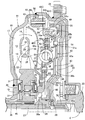
- FIG. 1 is a longitudinal sectional view of the torque converter according to the first embodiment.
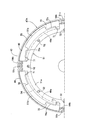
- FIG. 2 is a view of the damper mechanism as seen from the direction of arrows 2-2 in FIG.
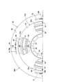
- FIG. 3 is a view of the dynamic damper mechanism as seen from the direction of arrows 3-3 in FIG.
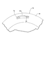
- FIG. 4 is a perspective view of the state in which the contact claw portion is inserted through the rotation restricting hole of the inertia plate as viewed from the lockup clutch side.
- FIG. 5 is a view showing the main part of FIG. 3 in a state where the relative rotation angle of the holding plate and the inertial rotating body is restricted.
- FIG. 5 is a view showing the main part of FIG. 3 in a state where the relative rotation angle of the holding plate and the inertial rotating body is restricted.
- FIG. 6 is a longitudinal sectional view of the torque converter according to the second embodiment.
- FIG. 7 is a longitudinal sectional view of the torque converter according to the third embodiment.
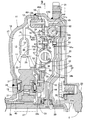
- FIG. 8 is a longitudinal sectional view of the torque converter of the fourth embodiment.
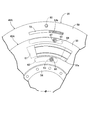
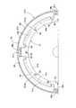
- FIG. 9 is a view of the damper mechanism as seen from the direction of arrows 9-9 in FIG. (Fourth embodiment)
- the torque converter includes a pump impeller 11 and a turbine runner disposed opposite to the pump impeller 11. 12 and a stator 13 disposed between the inner periphery of the pump impeller 11 and the turbine runner 12, as indicated by an arrow 14 between the pump impeller 11, the turbine runner 12 and the stator 13.
- a circulation circuit 15 for circulating the working oil is formed.
- the pump impeller 11 includes a bowl-shaped pump shell 16, a plurality of pump blades 17 provided on the inner surface of the pump shell 16, a pump core ring 18 that connects the pump blades 17, and an inner portion of the pump shell 16.
- a flange-shaped transmission cover 20 that covers the turbine runner 12 from the outside is joined to the outer periphery of the pump shell 16 by welding, and a ring gear 21 is fixed to the outer periphery of the transmission cover 20 by welding.
- a drive plate 22 is fastened to the ring gear 21.
- a crankshaft 23 of a vehicle engine E is coaxially fastened to the drive plate 22, and rotational power is input to the pump impeller 11 from the vehicle engine E.
- the turbine runner 12 has a bowl-shaped turbine shell 24, a plurality of turbine blades 25 provided on the inner surface of the turbine shell 24, and a turbine core ring 26 that connects the turbine blades 25.
- the end portion of the output shaft 27 that transmits the rotational power from the vehicle engine E to a transmission is connected to the bearing bush 28 on the bottomed cylindrical support cylinder portion 20a that the transmission cover 20 has integrally at the center thereof. Supported through.
- the output shaft 27 is spline-coupled to an output hub 29 disposed at a position spaced apart from the pump hub 19 in the axial direction, and a needle thrust bearing is provided between the output hub 29 and the transmission cover 20. 30 is interposed.
- the stator 13 includes a stator hub 31 disposed between the pump hub 19 and the output hub 29, a plurality of stator blades 32 provided on the outer periphery of the stator hub 31, and a stator core ring 33 that connects the outer periphery of the stator blades 32.
- a thrust bearing 34 is interposed between the pump hub 19 and the stator hub 31, and a thrust bearing 35 is interposed between the output hub 29 and the stator hub 31.
- a one-way clutch 37 is interposed between the stator hub 31 and a stator shaft 36 that surrounds the output shaft 27 that rotates together with the output hub 29 in a relatively rotatable manner. (Not shown) is supported in a non-rotatable manner.
- a clutch chamber 38 communicating with the circulation circuit 15 is formed between the transmission cover 20 and the turbine shell 24, and a lockup clutch 40 and an outer periphery of the output hub 29 are rotatable in the clutch chamber 38.
- the inertial rotating body 56 to be supported and the spring holder 42 ⁇ / b> A that sandwiches a part of the inertial rotating body 56 from both sides while allowing relative rotation within a limited range with respect to the inertial rotating body 56 are accommodated.
- the lockup clutch 40 has a clutch piston 43 that can be frictionally connected to the transmission cover 20 and switches between a connected state in which the clutch piston 43 is frictionally connected to the transmission cover 20 and a non-connected state in which the frictional connection is released.
- the inner periphery of the clutch piston 43 formed in a disc shape is supported by the output hub 29 so as to be axially movable and slidable.
- the clutch chamber 38 is partitioned by the clutch piston 43 into an inner chamber 38 a on the turbine runner 12 side and an outer chamber 38 b on the transmission cover 20 side, and is adjacent to the needle thrust bearing 30.
- An oil groove 44 formed in the output hub 29 communicates with the outer chamber 38 b, and the oil groove 44 communicates with the cylindrical output shaft 27.
- An oil passage 45 communicating with the inner periphery of the circulation circuit 15 is formed between the pump hub 19 and the stator shaft 36.
- the oil pump 44 and the oil reservoir (not shown) are alternately connected to the oil groove 44 and the oil passage 45.
- the pump impeller 11, the turbine runner 12, and the stator 13 circulate in the circulation circuit 15 in this order, and the rotational torque of the pump impeller 11 passes through the turbine runner 12, the spring holder 42 ⁇ / b> A, and the output hub 29 to the output shaft. 27.
- stator 13 In a state where a torque amplifying action is generated between the pump impeller 11 and the turbine runner 12, the accompanying reaction force is borne by the stator 13, and the stator 13 is fixed by the locking action of the one-way clutch 37. Further, when the torque amplification action is finished, the stator 13 rotates in the same direction together with the pump impeller 11 and the turbine runner 12 while idling the one-way clutch 37 by reversing the torque direction received by the stator 13.
- the damper mechanism 47 ⁇ / b> A is a plurality of damper mechanisms disposed at equal intervals in the circumferential direction between the spring holding member 51 fixed to the clutch piston 43 and the spring holder 42 ⁇ / b> A.
- the damper mechanism 47 ⁇ / b> A is a plurality of damper mechanisms disposed at equal intervals in the circumferential direction between the spring holding member 51 fixed to the clutch piston 43 and the spring holder 42 ⁇ / b> A.
- four coil-shaped damper springs 49 are interposed.
- An annular housing recess 50 is formed on the outer surface of the clutch piston 43 opposite to the transmission cover 20, and the damper is housed in the housing recess 50 at equal intervals in the circumferential direction.
- the spring holding member 51 that holds the spring 49 between the clutch piston 43 is fixed to the clutch piston 43.
- the spring holding member 51 has an outer periphery substantially corresponding to the inner periphery of the housing recess 50 and is disposed coaxially with the clutch piston 43, and the damper along the radial direction of the clutch piston 43. It is formed in a circular arc cross section so as to cover the inner side of the spring 49, and is continuously provided at four locations spaced at equal intervals in the circumferential direction of the outer periphery of the ring plate portion 51a and in the circumferential direction of the clutch piston 43.
- a spring cover portion 51b formed long along the spring cover portion 51b is disposed between the spring cover portions 51b and protrudes radially outward from the spring cover portion 51b on the outer periphery of the ring plate portion 51a.
- the ring plate portion 51 a is formed by a plurality of rivets 52 so as to integrally have a spring contact portion 51 c provided continuously. It is fixed to the Tchipisuton 43.
- the spring contact portion 51c is disposed between the four damper springs 49, and when the lock-up clutch 40 is in a disconnected state, the spring contact portion 51c is disposed on the dampers on both sides thereof. It contacts the end of the spring 49.
- the dynamic damper mechanism 48 ⁇ / b> A includes a spring holder 42 ⁇ / b> A that rotates together with the output hub 29 that is a rotation transmission member that constitutes a part of the torque transmission path 46 ⁇ / b> A, and an inertia rotating body 56.
- a plurality of, for example, six dynamic damper springs 57 having a coil shape are interposed therebetween.
- the spring holder 42A is composed of a pair of holding plates 54 and 55 that are connected to each other so as not to rotate relative to each other.
- the holding plates 54 and 55 are arranged at intervals in the axial direction of the output shaft 27 while rotating together with the output hub 29 which is a rotational transmission member constituting a part of the torque transmission path 46A.
- the holding plate 54 on the turbine runner 12 side is fixed to the output hub 29 by a plurality of rivets 53 together with the inner peripheral portion of the turbine shell 24 in the turbine runner 12.
- the inertia rotating body 56 is sandwiched between a pair of holding plates 54 and 55 constituting the spring holder 42A, and an inner peripheral portion is rotatably supported by the output hub 29. , And an additional weight member 59 fixed to the outer periphery of the inertia plate 58 with a rivet 60.
- Spring holding portions 54a and 55a for holding the dynamic damper spring 57 are provided at a plurality of places, for example, four places, at equal intervals in the circumferential direction of the holding plates 54 and 55. It is formed to face the outside.
- a portion of the inertia plate 58 corresponding to the spring holding portions 54a and 55a has a spring accommodation hole 61 for accommodating a part of the dynamic damper spring 57.
- the inertia plate 58 is formed so that both end portions of the spring accommodating hole 61 along the circumferential direction 58 are in contact with both end portions of the dynamic damper spring 57.
- the inertia plate 58 is formed such that an outer peripheral portion thereof protrudes radially outward from the holding plates 54 and 55, and the additional weight member 59 is fixed to the outer peripheral portion of the inertia plate 58.
- a plurality of locations for example, four spaced apart in the circumferential direction of the inertial plate 58.
- Cylindrical spacers 63 that are respectively inserted into the long holes 62 provided in the places are interposed, and a pair of the holding plates is provided on the outer side of the spring accommodating hole 61 along the radial direction of the inertial rotating body 56.
- Cylindrical spacers 65 are inserted between the long holes 64 provided at a plurality of locations, for example, at four locations spaced at equal intervals in the circumferential direction of the inertia plate 58.
- the holding plates 54 and 55 are connected by rivets 66 and 67 that penetrate the spacers 63 and 65, respectively. That is, the inertia plate 58 can rotate relative to the spring holder 42A within a limited range in which the spacers 63 and 64 move within the long holes 62 and 64.
- One of the pair of holding plates 54 and 55 constituting the spring holder 42A in this embodiment, the holding plate 54 on the side opposite to the clutch piston 43 of the lockup clutch 40 of the holding plates 54 and 55 is provided on the holding plate 54.
- a plurality of contact claw portions 54b that sandwich the damper spring 49 with the spring contact portion 51c of the spring holding member 51 are integrally provided, and the damper mechanism 47A is connected to the clutch piston 43.
- a damper spring 49 is interposed between the spring contact portion 51c of the spring holding member 51 to be fixed and the contact claw portion 54b of the holding plate 54 in the spring holder 42A.
- the four contact claws 54b which is the same number as the number of the damper springs 49, are bent so as to swell from the outer periphery of the holding plate 54 to the side opposite to the damper springs 49, and the bent It is integrally provided on the holding plate 54 so as to extend in a direction along the axis of the output shaft 27 from the portion.
- the plate thickness of the holding plate 54 on the side where the contact claw portion 54 b is provided in the pair of holding plates 54 and 55 is set to be larger than the plate thickness of the other holding plate 55.
- the spring holding member 51 fixed to the clutch piston 43 is formed with a plurality of notches 70 arranged between the plurality of spring cover portions 51b.
- the claw portion 54 b is inserted through the notch portion 70.
- the notches 70 are formed at a plurality of, for example, four places that are long in the circumferential direction and are equally spaced in the circumferential direction of the spring holding member 51 so as to open to the front end side of the spring cover 51b. Moreover, the notch 70 is arranged such that the inner end 70a of the notch 70 along the radial direction of the output shaft 27 is located outward from the inner end 49a of the damper spring 49 in the radial direction.
- the spring holding member 51 is formed. That is, as shown in FIG. 1, on the projection onto the plane passing through the axis of the contact claw 54 b and the output shaft 27, it passes through the inner end 49 a of the damper spring 49 and is parallel to the axis of the output shaft 27.
- the inner end 70a of the cutout portion 70 is disposed at an outer position along the radial direction with respect to an imaginary straight line L extending in the vertical direction.
- the spring contact portion 51c is disposed so as to be located at the center in the circumferential direction of the notch portion 70 when viewed from the spring holder 42A side, and both sides of the base portion of the spring contact portion 51c.
- a recess 71 for forming the spring cover portion 51b in an arc shape in cross section so as to cover the damper spring 49 is formed to be continuous with the notch portion 70.
- the contact claw portion 54 b is a part of the contact claw portion 54 b on the projection view on the plane passing through the axis of the contact claw portion 54 b and the output shaft 27.
- a rotation restricting hole 72 extending in the circumferential direction is formed in the inertia plate 58, as shown in FIGS.
- the contact claw portion 54 b is inserted into the rotation restriction hole 72 so that a part of the contact claw part 54 b is accommodated in the rotation restriction hole 72.
- the rotation restricting hole 72 has a pair of the holding plates 54 and 55 and the inertia as a result of the contact pawl portion 54b coming into contact with the circumferential end of the rotation restricting hole 72. It is formed so as to regulate the relative rotation angle of the rotating body 56.
- the damper mechanism 47A has a plurality of damper springs 49 and a circular arc cross section so that the damper springs 49 are held between the clutch pistons 43.
- a pair of spring holding members 51 that are fixed to the clutch piston 43 while having a plurality of spring cover portions 51b formed on the same, and a part of the dynamic damper mechanism 48A that sandwich the inertia plate 58 of the inertia rotating body 56.
- a plurality of contact claw portions 54b sandwiching the damper spring 49 with the spring holding member 51, and the contact claw portions 54b are inserted therethrough.
- the radial direction of the output shaft 27 of the notch 70 formed in the spring holding member 51 is along.
- the end 70a is disposed outward from the inner end 49a of the damper spring 49 in the radial direction, and the contact claw portion 54b is in a plane passing through the contact claw portion 54b and the axis of the output shaft 27. Is formed so that a part of the contact claw portion 54b overlaps the inertia plate 58, so that the contact claw portion 54b can avoid the interference with the spring cover portion 51b and the radius of the output shaft 27 can be avoided. It is possible to dispose the damper spring 49 to the outer side in the direction, and to reduce the axial distance between the clutch piston 43 and the dynamic damper mechanism 48A while maintaining the holding function of the damper spring 49 by the spring holding member 51. Become.
- the abutment claw portion 54b is provided integrally with the holding plate 54 of the pair of holding plates 54, 55 opposite to the clutch piston 43 of the lockup clutch 40, and the clutch piston 43 and the dynamic damper.
- the axial distance between the mechanisms 48A can be further shortened.
- the tip of the abutment claw 54b passes through the center C of the damper spring 49 or is disposed at a position outward from the center C of the output shaft 27 in the radial direction.
- the damper spring 49 is compressed, the damper spring 49 is prevented from bending so as to bulge outward in the radial direction of the output shaft 27, and a frictional force is generated by the frictional contact between the damper spring 49 and the clutch piston 43. Can be suppressed.
- the inertia plate 58 accommodates a part of the contact claw portion 54 b and extends in the circumferential direction so that the rotation restriction hole 72 extends to the circumferential end of the rotation restriction hole 72. Since the relative rotation angle between the pair of holding plates 54 and 55 and the inertial rotating body 56 is regulated by the contact, the relative rotation angle between the pair of holding plates 54 and 55 and the inertial rotating body 56 can be simplified. Therefore, it is possible to prevent an excessive load from being applied to the dynamic damper spring 57 of the dynamic damper mechanism 48A.
- the torque transmission path 46B is provided with at least one (in this embodiment, one) damper mechanism 47B and a dynamic damper mechanism 48B.
- the damper mechanism 47B includes a plurality of, for example, four coil-shaped dampers arranged at equal intervals in the circumferential direction between the spring holding member 51 fixed to the clutch piston 43 and the spring holder 42B.
- a spring 49 is interposed.
- the dynamic damper mechanism 48B includes a plurality of, for example, six coils between a spring holder 42B that rotates together with the output hub 29 that is a rotational transmission member that constitutes a part of the torque transmission path 46B, and the inertia rotating body 56.
- a dynamic damper spring 57 having a shape is interposed.
- the spring holder 42B includes a pair of holding plates 74 and 75 that are connected to each other so as not to be relatively rotatable.
- the holding plates 74 and 75 constitute a part of the torque transmission path 46B. While being rotated together with the output hub 29 which is a rotation transmission member, the output shaft 27 is arranged at an interval in the axial direction.
- the holding plate 74 on the turbine runner 12 side of the pair of holding plates 74 and 75 is fixed to the output hub 29 by a plurality of rivets 53 together with the inner peripheral portion of the turbine shell 24 in the turbine runner 12.
- the inertia rotating body 56 is sandwiched between a pair of holding plates 74 and 75 constituting the spring holder 42B, and an inner peripheral portion is rotatably supported by the output hub 29. And an additional weight member 59 fixed to the outer periphery of the inertia plate 58.
- Spring holding parts 74a and 75a for holding the dynamic damper spring 57 are provided at a plurality of places, for example, four places, at equal intervals in the circumferential direction of the holding plates 74 and 75. It is formed to face the outside.
- a portion of the inertia plate 58 corresponding to the spring holding portions 74a and 75a has a spring accommodation hole 61 for accommodating a part of the dynamic damper spring 57.
- the inertia plate 58 is formed so that both end portions of the spring accommodating hole 61 along the circumferential direction 58 are in contact with both end portions of the dynamic damper spring 57.
- a plurality of locations for example, 4 spaced apart at equal intervals in the circumferential direction of the inertial plate 58.
- Cylindrical spacers 63 that are respectively inserted into the long holes 62 provided in the places are interposed, and the holding plates 74 and 75 are connected by a rivet 66 that penetrates the spacer 63.
- the holding plate 74 on the opposite side of the lock-up clutch 40 from the clutch piston 43 is included in the holding plate 74 and 75.
- the damper spring 49 is inserted into the notch portion 70 formed in the spring holding member 51 fixed to the clutch piston 43 so as to sandwich the damper spring 49 between the spring holding portion 51c of the spring holding member 51.
- a plurality of abutting claw portions 74b are integrally provided, and the damper mechanism 47B is configured to abut the spring abutting portion 51c of the spring holding member 51 fixed to the clutch piston 43 and the holding plate 74 in the spring holder 42B.
- a damper spring 49 is interposed between the claw portions 74b.
- the plate thickness of the holding plate 74 on the side where the contact claw portion 74b is provided in the pair of holding plates 74 and 75 is set larger than the plate thickness of the other holding plate 75.
- the contact claw portion 74b is bent so that a part of the contact claw portion 74b overlaps the inertia plate 58 on a projection view on a plane passing through the corresponding contact claw portion 74b and the axis of the output shaft 27.
- the inertia plate 58 is formed with a rotation restricting hole 76 that extends long in the circumferential direction, and a part of the contact claw portion 74b is the rotation restricting hole.
- the rotation restricting hole 76 is inserted so as to be accommodated in 76.
- the other of the pair of holding plates 74 and 75 that is, a part of the holding plate 75 is disposed in the rotation restricting hole 76 and abutted and fixed to the contact claw portion 74b.
- a mounting plate portion 75 b that is integrally connected to the outer periphery of the holding plate 75 and is disposed in the rotation restricting hole 76 is disposed in the rotation restricting hole 76 and is in contact with the contact claw. It abuts on the portion 74 b and is caulked and fixed to the abutment claw portion 74 b with a rivet 77.
- the same effect as that of the first embodiment can be obtained, and the pair of holding plates 74 can be provided on the outer side of the dynamic damper spring 57 in the radial direction of the output shaft 27. , 75 is not required, and a spacer arranged so as to be interposed between the two holding plates 74, 75 is not necessary, and the cost can be reduced.
- torque transmitted from the vehicle engine E to the transmission cover 20 passes through the torque transmission path 46C including the clutch piston 43, the spring holder 42C and the output hub 29 to the output shaft 27.
- the torque transmission path 46C is provided with at least one (one in this embodiment) damper mechanism 47C and a dynamic damper mechanism 48C.
- the damper mechanism 47C includes a plurality of, for example, four coil-shaped dampers arranged at equal intervals in the circumferential direction between the spring holding member 51 fixed to the clutch piston 43 and the spring holder 42C.
- a spring 49 is interposed.
- the dynamic damper mechanism 48C includes a plurality of, for example, six coils between the spring holder 42C that rotates together with the output hub 29 that is a rotation transmission member that constitutes a part of the torque transmission path 46C, and the inertia rotating body 56.
- a dynamic damper spring 57 having a shape is interposed.
- the spring holder 42C includes a pair of holding plates 84 and 85 that constitute a part of the torque transmission path 46C, and the holding plates 84 and 85 constitute a part of the torque transmission path 46C.
- the output shaft 27 is arranged with an interval in the axial direction while rotating together with the output hub 29 which is a rotational transmission member.
- the holding plate 84 on the turbine runner 12 side of the pair of holding plates 84 and 85 is fixed to the output hub 29 by a plurality of rivets 53 together with the inner peripheral portion of the turbine shell 24 in the turbine runner 12.
- the inertia rotator 56 is sandwiched between a pair of the holding plates 84 and 85 constituting the spring holder 42C, and an inner peripheral portion is rotatably supported by the output hub 29. And an additional weight member 59 fixed to the outer periphery of the inertia plate 58.
- Spring holding portions 84a and 85a for holding the dynamic damper spring 57 are provided at a plurality of, for example, four places at equal intervals in the circumferential direction of the holding plates 84 and 85. It is formed to face the outside.
- a portion of the inertia plate 58 corresponding to the spring holding portions 84a and 85a has a spring accommodation hole 61 for accommodating a part of the dynamic damper spring 57.
- the inertia plate 58 is formed so that both end portions of the spring accommodating hole 61 along the circumferential direction 58 are in contact with both end portions of the dynamic damper spring 57.
- a plurality of locations for example, 4 spaced at equal intervals in the circumferential direction of the inertial plate 58.
- Cylindrical spacers 63 that are respectively inserted into the long holes 62 provided in the places are interposed, and a pair of the holding plates is provided on the outer side of the spring accommodating hole 61 along the radial direction of the inertial rotating body 56.
- Cylindrical spacers 65 that are respectively inserted into a plurality of long holes 64 provided at a plurality of, for example, four places at equal intervals in the circumferential direction of the inertia plate 58 are interposed between the 84 and 85.
- the holding plates 84 and 85 are connected by rivets 66 and 67 that penetrate the spacers 63 and 65.
- the holding plate 85 on the clutch piston 43 side of the lock-up clutch 40 of the holding plates 84 and 85 is included in the clutch.
- the damper spring 49 is inserted into a notch portion 70 formed in the spring holding member 51 fixed to the piston 43 so as to sandwich the damper spring 49 between the spring abutting portion 51 c of the spring holding member 51.
- a contact claw portion 85b is integrally provided, and the damper mechanism 47C includes a spring contact portion 51c of a spring holding member 51 fixed to the clutch piston 43 and a contact claw portion 85b of the holding plate 85 in the spring holder 42C.
- a damper spring 49 is interposed therebetween.
- the plate thickness of the holding plate 85 on the side of the pair of holding plates 84 and 85 where the contact claw portion 85b is provided is set to be larger than the plate thickness of the other holding plate 84.
- the contact claw portion 85b is bent so that a part of the contact claw portion 85b overlaps the inertia plate 58 on a projection view on a plane passing through the corresponding contact claw portion 85b and the axis of the output shaft 27.
- a rotation restricting hole 86 extending in the circumferential direction is formed in the inertia plate 58, and a part of the contact claw 85b is formed in the rotation restricting hole 86.
- the contact claw portion 85b is integrally provided on the holding plate 85 on the clutch piston 43 side of the lock-up clutch 40 of the pair of holding plates 84 and 85.
- the axial distance between the clutch piston 43 and the dynamic damper mechanism 48C can be shortened while maintaining the function of holding the damper spring 49 by the spring holding member 51.
- a fourth embodiment of the present invention will be described with reference to FIG. 8 and FIG. 9, but the portions corresponding to the first to third embodiments are only shown with the same reference numerals. Detailed description will be omitted.
- the torque transmission path 46A including the clutch piston 43, the spring holder 42A and the output hub 29 to the output shaft 27.
- the torque transmission path 46A is provided with at least one (one in this embodiment) damper mechanism 47D and a dynamic damper mechanism 48A.
- the damper mechanism 47D includes a plurality of, for example, four coil-shaped dampers arranged at equal intervals in the circumferential direction between a spring holding member 91 fixed to the clutch piston 43 and the spring holder 42A.
- a spring 49 is interposed.
- An annular housing recess 50 is formed on the outer surface of the clutch piston 43 opposite to the transmission cover 20, and the damper is housed in the housing recess 50 at equal intervals in the circumferential direction.
- the spring holding member 91 that holds the spring 49 between the clutch piston 43 is fixed to the clutch piston 43.
- the spring holding member 91 has an outer periphery substantially corresponding to the inner periphery of the housing recess 50 and is disposed coaxially with the clutch piston 43, and the damper along the radial direction of the clutch piston 43.
- a circular cross section is formed so as to cover the inner side of the spring 49, and is continuously provided at four locations at equal intervals in the circumferential direction of the outer periphery of the ring plate portion 91 a and in the circumferential direction of the clutch piston 43.
- a spring cover portion 91b that is formed along the length of the ring plate portion 91b.
- the spring cover portion 91b is disposed between the spring cover portions 91b and protrudes radially outward from the spring cover portion 91b.
- the ring plate portion 91a is formed by a plurality of rivets 52 so as to have a spring contact portion 91c provided continuously. It is fixed to the Tchipisuton 43.
- the spring abutting portion 91c is disposed between the four damper springs 49, and when the lock-up clutch 40 is in a disconnected state, the spring abutting portion 91c It contacts the end of the spring 49.
- the holding plate 54 is integrally provided with a plurality of contact claw portions 54 b that sandwich the damper spring 49 with the spring contact portion 91 c of the spring holding member 91.
- the spring cover portion 91b is formed so that at least a part of the spring cover portion 91b is positioned outward from the inner end 49a of the damper spring 49 in the radial direction of the output shaft 27.
- the outer end 91ba of the spring cover portion 91b along the radial direction is located at an outer position along the radial direction, and the contact claw portion 54b is formed of the spring cover portion along the radial direction. It can abut against the damper spring 49 outside 91b.
- concave portions 92 are formed so as to cover the damper spring 49 and to form the spring cover portion 91b in a cross-sectional arc shape.
- the contact claw portion 54b is configured such that a part of the contact claw portion 54b overlaps the inertia plate 58 on a projection view on a plane passing through the contact claw portion 54b and the axis of the output shaft 27.
- a part of the contact claw 54b is accommodated in the rotation restricting hole 72 formed in the inertia plate 58 so as to extend long in the circumferential direction. It is inserted like this.
- the spring holding member 91 does not have a function of restricting the circumferential relative position of the contact claw portion 54b with respect to the clutch piston 43, the damper spring 49 is brought into a close contact state in the axial direction thereof.
- the relative position in the circumferential direction of the abutment claw portion 54b with respect to the piston 43 is restricted, and there is an advantage that the spring holding member 91 is not required to have a large strength and the spring holding member 91 can be made thin.
- the axial distance between the clutch piston 43 and the dynamic damper mechanism 48A while maintaining the holding function of the damper spring 49 by the spring holding member 91, as in the first embodiment. Can be shortened.
Abstract
ダイナミックダンパ機構の一部を構成する一対の保持板の一方に一体に設けられる当接爪部が、クラッチピストンに固定されるスプリング保持部材が有する切欠き部に挿通されるトルクコンバータにおいて、出力シャフト(27)の半径方向に沿う切欠き部(70)の内端(70a)が、前記半径方向でダンパスプリング(49)の内側端(49a)よりも外方に位置するようにして切欠き部(70)が形成され、当接爪部(54b)が、該当接爪部(54b)および出力シャフト(27)の軸線を通る平面への投影図上で当接爪部(54b)の一部を慣性プレート(58)に重ねるように形成される。これにより、スプリング保持部材によるダンパスプリングの保持機能を維持しつつ、クラッチピストンおよびダイナミックダンパ機構間の軸方向距離を短くすることができる。
Description
本発明は、ポンプインペラに結合される伝動カバーに摩擦接続可能なクラッチピストンを有するロックアップクラッチの接続状態で前記クラッチピストンおよび出力シャフト間でトルクを伝達するトルク伝達経路に、当該トルク伝達経路の一部を構成する回転伝動部材とともに回転するようにしつつ前記出力シャフトの軸線方向に間隔をあけて配置される一対の保持板と、それらの保持板間に挟まれる慣性プレートを有する慣性回転体と、前記保持板および前記慣性プレート間に設けられるダイナミックダンパスプリングとを有するダイナミックダンパ機構が付設され、複数個のダンパスプリングと、それらのダンパスプリングを前記クラッチピストンとの間に保持するようにして横断面円弧状に形成されるスプリングカバー部ならびにそれらのスプリングカバー間に配置される複数の切欠き部を有しつつ前記クラッチピストンに固定されるスプリング保持部材と、前記切欠き部に挿通されて前記ダンパスプリングを前記スプリング保持部材との間に挟むようにしつつ一対の前記保持板の一方に一体に設けられる複数の当接爪部とから成るダンパ機構が、前記トルク伝達経路に介設されるトルクコンバータに関する。
このようなトルクコンバータは、特許文献1で知られている。このものでは、スプリング保持部材が有する切欠き部に、一対の保持板のうちクラッチピストン側の保持板に一体に設けられた当接爪部が挿通され、この当接爪部は、前記クラッチピストン側に近接するにつれて該クラッチピストンの半径方向に沿う外方位置となるように傾斜して形成されている。
ところで、前記クラッチピストンおよびトルクコンバータの軸線方向でのコンパクト化を図るためには、前記クラッチピストンおよびダイナミックダンパ機構間の軸方向距離を短くすることが望ましいが、上記特許文献1で開示されるものでは、一対の保持板のうちクラッチピストン側の保持板に当接爪部が一体に形成され、この当接爪部が傾斜してクラッチピストン側に延びるように形成されているので、前記クラッチピストンおよびダイナミックダンパ機構間の軸方向距離を短くすると、スプリング保持部材のスプリングカバー部との当接爪部の干渉を回避すべく、当接爪部を出力シャフトの半径方向でより内方側に配置せざるを得ない。そうすると、当接爪部を挿通させるようにしてスプリング保持部材に形成される切欠き部の前記半径方向に沿う内端を、前記半径方向に沿ってより内方側に配置する必要が生じ、スプリング保持部材によるダンパスプリングの保持機能が低下する可能性がある。
本発明は、かかる事情に鑑みてなされたものであり、スプリング保持部材によるダンパスプリングの保持機能を維持しつつ、クラッチピストンおよびダイナミックダンパ機構間の軸方向距離を短くすることを可能としたトルクコンバータを提供することを目的とする。
上記目的を達成するために、本発明は、ポンプインペラに結合される伝動カバーに摩擦接続可能なクラッチピストンを有するロックアップクラッチの接続状態で前記クラッチピストンおよび出力シャフト間でトルクを伝達するトルク伝達経路に、当該トルク伝達経路の一部を構成する回転伝動部材とともに回転するようにしつつ前記出力シャフトの軸線方向に間隔をあけて配置される一対の保持板と、それらの保持板間に挟まれる慣性プレートを有する慣性回転体と、前記保持板および前記慣性プレート間に設けられるダイナミックダンパスプリングとを有するダイナミックダンパ機構が付設され、複数個のダンパスプリングと、それらのダンパスプリングを前記クラッチピストンとの間に保持するようにして横断面円弧状に形成されるスプリングカバー部ならびにそれらのスプリングカバー部間に配置される複数の切欠き部を有しつつ前記クラッチピストンに固定されるスプリング保持部材と、前記切欠き部に挿通されて前記ダンパスプリングを前記スプリング保持部材との間に挟むようにしつつ一対の前記保持板の一方に一体に設けられる複数の当接爪部とから成るダンパ機構が、前記トルク伝達経路に介設されるトルクコンバータにおいて、前記出力シャフトの半径方向に沿う前記切欠き部の内端が、前記半径方向で前記ダンパスプリングの内側端よりも外方に位置するようにして前記切欠き部が形成され、前記当接爪部が、その当接爪部および前記出力シャフトの軸線を通る平面への投影図上で前記当接爪部の一部を前記慣性プレートに重ねるように形成されることを第1の特徴とする。
また本発明は、第1の特徴の構成に加えて、前記慣性プレートに、前記当接爪部の一部を収容して周方向に長く延びる回転規制孔が、当該回転規制孔の周方向端部への前記当接爪部の当接によって一対の前記保持板および前記慣性回転体の相対回転角度を規制するようにして形成されることを第2の特徴とする。
本発明は、第2の特徴の構成に加えて、一対の前記保持板の他方の一部が、前記回転規制孔内に配置されるとともに前記当接爪部に当接してかしめ固定されることを第3の特徴とする。
さらに本発明は、ポンプインペラに結合される伝動カバーに摩擦接続可能なクラッチピストンを有するロックアップクラッチの接続状態で前記クラッチピストンおよび出力シャフト間でトルクを伝達するトルク伝達経路に、当該トルク伝達経路の一部を構成する回転伝動部材とともに回転するようにしつつ前記出力シャフトの軸線方向に間隔をあけて配置される一対の保持板と、それらの保持板間に挟まれる慣性プレートを有する慣性回転体と、前記保持板および前記慣性プレート間に設けられるダイナミックダンパスプリングとを有するダイナミックダンパ機構が付設され、複数個のダンパスプリングと、それらのダンパスプリングを前記クラッチピストンとの間に保持するようにして横断面円弧状に形成される複数のスプリングカバー部を有しつつ前記クラッチピストンに固定されるスプリング保持部材と、前記ダンパスプリングを前記スプリング保持部材との間に挟むようにしつつ一対の前記保持板の一方に一体に設けられる複数の当接爪部とから成るダンパ機構が、前記トルク伝達経路に介設されるトルクコンバータにおいて、前記スプリングカバー部は、その少なくとも一部が前記半径方向で前記ダンパスプリングの内側端よりも外方に位置するように形成され、前記半径方向に沿う前記スプリングカバー部の外方で前記ダンパスプリングに当接し得る前記当接爪部が、その当接爪部および前記出力シャフトの軸線を通る平面への投影図上で前記当接爪部の一部を前記慣性プレートに重ねるように形成されることを第4の特徴とする。
本発明の第1の特徴によれば、出力シャフトの半径方向に沿う切欠き部の内端が前記半径方向でダンパスプリングの内側端よりも外方に在り、当接爪部の一部が、当接爪部および出力シャフトの軸線を通る平面への投影図上で慣性プレートに重なるので、当接爪部をスプリングカバー部との干渉を回避しつつ出力シャフトの半径方向でより外方側に配置することが可能となり、スプリング保持部材によるダンパスプリングの保持機能を維持しつつ、クラッチピストンおよびダイナミックダンパ機構間の軸方向距離を短くすることが可能となる。
また本発明の第2の特徴によれば、前記慣性プレートに形成された回転規制孔に当接爪部の一部が収容されるようにした簡単な構成で、一対の保持板および慣性回転体の相対回転角度が規制され、ダイナミックダンパ機構のダイナミックダンパスプリングに過大な荷重がかかることを防止することができる。
本発明の第3の特徴によれば、一対の保持板のうち当接爪部が設けられていない側の保持板の一部が回転規制孔内で当接爪部に当接しつつかしめ固定されるので、一対の保持板間に介在するように配置されるスペーサが不要となり、コストダウンを図ることができる。
さらに本発明の第4の特徴によれば、スプリングカバー部の少なくとも一部が出力シャフトの半径方向でダンパスプリングの内側端よりも外方に在り、前記半径方向に沿う前記スプリングカバー部の外方でダンパスプリングに当接し得る前記当接爪部の一部が、当接爪部および出力シャフトの軸線を通る平面への投影図上で慣性プレートに重なるので、当接爪部のスプリングカバー部との干渉を回避しつつスプリング保持部材によるダンパスプリングの保持機能を維持し、クラッチピストンおよびダイナミックダンパ機構間の軸方向距離を短くすることが可能となる。
11・・・ポンプインペラ
20・・・伝動カバー
27・・・出力シャフト
29・・・回転伝動部材である出力ハブ
40・・・ロックアップクラッチ
43・・・クラッチピストン
46A,46B,46C・・・トルク伝達経路
47A,47B,47C,47D・・・ダンパ機構
48A,48B,48C・・・ダイナミックダンパ機構
49・・・ダンパスプリング
49a・・・ダンパスプリングの内側端
51,91・・・スプリング保持部材
51b,91b・・・スプリングカバー部
54,55,74,75,84,85・・・保持板
54b,74b,85b・・・当接爪部
56・・・慣性回転体
57・・・ダイナミックダンパスプリング
58・・・慣性プレート
70・・・切欠き部
70a・・・切欠き部の内端
72,76,86・・・回転規制孔
以下、本発明の実施の形態を、添付の図面を参照しながら説明する。
本発明の第1の実施の形態について図1~図5を参照しながら説明すると、先ず図1において、このトルクコンバータは、ポンプインペラ11と、このポンプインペラ11に対向して配置されるタービンランナ12と、前記ポンプインペラ11および前記タービンランナ12の内周部間に配置されるステータ13とを備え、前記ポンプインペラ11、前記タービンランナ12および前記ステータ13間には、矢印14で示すように作動オイルを循環させる循環回路15が形成される。
前記ポンプインペラ11は、椀状のポンプシェル16と、該ポンプシェル16の内面に設けられる複数のポンプブレード17と、それらのポンプブレード17を連結するポンプコアリング18と、前記ポンプシェル16の内周部にたとえば溶接によって固定されるポンプハブ19とを有し、前記ポンプハブ19には、トルクコンバータに作動オイルを供給するオイルポンプ(図示せず)が連動、連結される。
また前記ポンプシェル16の外周部には、前記タービンランナ12を外側から覆う椀状の伝動カバー20が溶接によって結合されており、この伝動カバー20の外周部にリングギヤ21が溶接によって固着され、前記リングギヤ21には駆動板22が締結される。また駆動板22には、車両用エンジンEのクランクシャフト23が同軸に締結されており、前記ポンプインペラ11には、車両用エンジンEから回転動力が入力される。
前記タービンランナ12は、椀状のタービンシェル24と、該タービンシェル24の内面に設けられる複数のタービンブレード25と、それらのタービンブレード25を連結するタービンコアリング26とを有する。
前記車両用エンジンEからの回転動力を図示しないミッションに伝達する出力シャフト27の端部は、前記伝動カバー20がその中心部に一体に有する有底円筒状の支持筒部20aに、軸受ブッシュ28を介して支持される。前記出力シャフト27は、前記ポンプハブ19との間に軸方向の間隔をあけた位置に配置される出力ハブ29にスプライン結合されており、前記出力ハブ29および前記伝動カバー20間にはニードルスラストベアリング30が介装される。
前記ステータ13は、前記ポンプハブ19および前記出力ハブ29間に配置されるステータハブ31と、このステータハブ31の外周に設けられる複数のステータブレード32と、それらのステータブレード32の外周を連結するステータコアリング33とを有し、前記ポンプハブ19および前記ステータハブ31間にはスラストベアリング34が介装され、前記出力ハブ29および前記ステータハブ31間にはスラストベアリング35が介装される。
前記ステータハブ31と、前記出力ハブ29とともに回転する前記出力シャフト27を相対回転自在に囲繞するステータシャフト36との間には、一方向クラッチ37が介設され、前記ステータシャフト36は、ミッションケース(図示せず)に回転不能に支持される。
前記伝動カバー20および前記タービンシェル24間には、前記循環回路15に連通するクラッチ室38が形成され、このクラッチ室38内に、ロックアップクラッチ40と、前記出力ハブ29の外周に回転自在に支持される慣性回転体56と、当該慣性回転体56に対して制限された範囲での相対回転を可能としつつ前記慣性回転体56の一部を両側から挟むスプリングホルダ42Aとが収容される。
前記ロックアップクラッチ40は、前記伝動カバー20に摩擦接続可能なクラッチピストン43を有するとともに該クラッチピストン43を前記伝動カバー20に摩擦接続させた接続状態ならびに摩擦接続を解除した非接続状態を切替えることが可能であり、円板状に形成される前記クラッチピストン43の内周部は、前記出力ハブ29に軸方向移動を可能として摺動可能に支持される。
前記クラッチ室38内は、前記クラッチピストン43によって、前記タービンランナ12側の内側室38aと、前記伝動カバー20側の外側室38bとに区画されており、前記ニードルスラストベアリング30に隣接して前記出力ハブ29に形成される油溝44が前記外側室38bに連通され、前記油溝44は円筒状の前記出力シャフト27内に連通する。また前記ポンプハブ19および前記ステータシャフト36間には、前記循環回路15の内周部に通じる油路45が形成される。前記油溝44および前記油路45には、前記オイルポンプおよびオイル溜め(図示せず)が交互に接続される。
車両用エンジンEのアイドリング時や、極低速運転域では、前記油溝44から前記外側室38bに作動油が供給され、前記油路45から作動油が導出されており、この状態では外側室38bの方が内側室38aよりも高圧となり、前記クラッチピストン43は前記伝動カバー20の内面から離反する側に押されており、ロックアップクラッチ40は非接続状態となっている。この状態では、ポンプインペラ11およびタービンランナ12の相対回転は許容されており、車両用エンジンEによってポンプインペラ11が回転駆動されることで前記循環回路15内の作動油が、矢印14で示すように、ポンプインペラ11、タービンランナ12、ステータ13の順に循環回路15内を循環し、前記ポンプインペラ11の回転トルクが前記タービンランナ12、前記スプリングホルダ42Aおよび前記出力ハブ29を介して前記出力シャフト27に伝達される。
前記ポンプインペラ11および前記タービンランナ12間でトルクの増幅作用が生じている状態では、それに伴う反力がステータ13で負担され、ステータ13は、前記一方向クラッチ37のロック作用によって固定される。またトルク増幅作用を終えたときに、前記ステータ13は、該ステータ13が受けるトルク方向の反転によって一方向クラッチ37を空転させながらポンプインペラ11およびタービンランナ12とともに同一方向に回転する。
このようなトルクコンバータがカップリング状態となったとき、もしくはカップリング状態に近づいたときには、前記油路45から前記内側室38aに作動油が供給され、前記油溝44から作動油が導出されるように、前記油溝44および前記油路45と、前記オイルポンプおよびオイル溜めとの接続状態が切替えられる。その結果、クラッチ室38内では内側室38aの方が外側室38bよりも高圧となり、その圧力差によってクラッチピストン43が前記伝動カバー20側に押圧され、前記クラッチピストン43の外周部が前記伝動カバー20の内面に圧接して伝動カバー20に摩擦接続され、ロックアップクラッチ40が接続状態となる。
前記ロックアップクラッチ40が接続状態となったときに、前記車両用エンジンEから前記伝動カバー20に伝わるトルクは、前記クラッチピストン43、前記スプリングホルダ42Aおよび前記出力ハブ29を含むトルク伝達経路46Aを経て、前記出力シャフト27に機械的に伝達されるものであり、このトルク伝達経路46Aには、少なくとも1つ(この実施の形態では1つ)のダンパ機構47Aが介設されるとともに、ダイナミックダンパ機構48Aが付設される。
図2を併せて参照して、前記ダンパ機構47Aは、前記クラッチピストン43に固定されるスプリング保持部材51と、前記スプリングホルダ42Aとの間に、周方向に等間隔をあけて配置される複数個たとえば4個のコイル状のダンパスプリング49が介設されて成る。
前記クラッチピストン43の外周部の前記伝動カバー20とは反対側の面には、環状の収容凹部50が形成されており、その収容凹部50内に周方向に等間隔をあけて収容されるダンパスプリング49を、前記クラッチピストン43との間に保持する前記スプリング保持部材51が前記クラッチピストン43に固定される。
前記スプリング保持部材51は、前記収容凹部50の内周にほぼ対応した外周を有して前記クラッチピストン43と同軸に配置されるリング板部51aと、前記クラッチピストン43の半径方向に沿う前記ダンパスプリング49の内方側を覆うように横断面円弧状に形成されて前記リング板部51aの外周の周方向に等間隔をあけた4箇所に連設されるとともに前記クラッチピストン43の周方向に沿って長く形成されるスプリングカバー部51bと、それらのスプリングカバー部51b相互間に配置されるとともに前記スプリングカバー部51bよりも半径方向外方に突出するようにして前記リング板部51aの外周に連設されるばね当接部51cとを一体に有するように形成され、前記リング板部51aが複数のリベット52で前記クラッチピストン43に固定される。
前記ばね当接部51cは、4個の前記ダンパスプリング49相互間に配置されており、前記ロックアップクラッチ40が非接続状態にあるときに、前記ばね当接部51cは、その両側の前記ダンパスプリング49の端部に当接する。
図3を併せて参照して、前記ダイナミックダンパ機構48Aは、前記トルク伝達経路46Aの一部を構成する回転伝動部材である前記出力ハブ29とともに回転するスプリングホルダ42Aと、慣性回転体56との間に、複数個たとえば6個のコイル状であるダイナミックダンパスプリング57が介設されて成る。
前記スプリングホルダ42Aは、相互に相対回転不能に連結される一対の保持板54,55で構成される。それらの保持板54,55は、前記トルク伝達経路46Aの一部を構成する回転伝動部材である前記出力ハブ29とともに回転するようにしつつ前記出力シャフト27の軸線方向に間隔をあけて配置され、一対の前記保持板54,55のうち前記タービンランナ12側の保持板54は、前記タービンランナ12における前記タービンシェル24の内周部とともに前記出力ハブ29に複数のリベット53で固定される。
前記慣性回転体56は、前記スプリングホルダ42Aを構成する一対の前記保持板54,55間に挟まれるとともに前記出力ハブ29に内周部が回転自在に支持される円板状の慣性プレート58と、その慣性プレート58の外周にリベット60で固定される付加重量部材59とから成る。
前記保持板54,55の周方向に等間隔をあけた複数箇所たとえば4箇所には、前記ダイナミックダンパスプリング57を保持するためのばね保持部54a,55aが、前記ダイナミックダンパスプリング57の一部を外部に臨ませるようにして形成される。前記慣性プレート58の前記ばね保持部54a,55aに対応する部分には、前記ダイナミックダンパスプリング57の一部を収容するばね収容孔61が、前記ロックアップクラッチ40の非接続状態では、前記慣性プレート58の周方向に沿う前記ばね収容孔61の両端部が前記ダイナミックダンパスプリング57の両端部に当接するようにして形成される。
前記慣性プレート58は、その外周部が前記保持板54,55よりも半径方向外方に突出するように形成されており、前記付加重量部材59が前記慣性プレート58の外周部に固定される。
前記慣性回転体56の半径方向に沿って前記ばね収容孔61の内方側で一対の前記保持板54,55間には、前記慣性プレート58の周方向に等間隔をあけた複数箇所たとえば4箇所に設けられた長孔62にそれぞれ挿通される円筒状のスペーサ63が介装され、また前記慣性回転体56の半径方向に沿って前記ばね収容孔61の外方側で一対の前記保持板54,55間には、前記慣性プレート58の周方向に等間隔をあけた複数箇所たとえば4箇所に設けられた長孔64にそれぞれ挿通される円筒状のスペーサ65が介装される。前記保持板54,55は、前記スペーサ63,65をそれぞれ貫通するリベット66,67で連結される。すなわち前記慣性プレート58は、前記長孔62,64内を前記スペーサ63,64が移動するだけの制限された範囲で、前記スプリングホルダ42Aに対して相対回転することが可能である。
前記スプリングホルダ42Aを構成する一対の前記保持板54,55の一方、この実施の形態では前記保持板54,55のうち前記ロックアップクラッチ40のクラッチピストン43とは反対側の保持板54には、前記ダンパスプリング49を前記スプリング保持部材51の前記ばね当接部51cとの間に挟むようにした複数の当接爪部54bが一体に設けられ、前記ダンパ機構47Aは、前記クラッチピストン43に固定されるスプリング保持部材51のばね当接部51cと、前記スプリングホルダ42Aにおける保持板54の当接爪部54bとの間にダンパスプリング49が介設されて成る。
この実施の形態では、前記ダンパスプリング49の個数と同数である4個の当接爪部54bが、前記保持板54の外周から前記ダンパスプリング49とは反対側に膨らむように屈曲し、その屈曲部から前記出力シャフト27の軸線に沿う方向に延びるようにして前記保持板54に一体に設けられる。しかも前記当接爪部54bの先端は、前記ダンパスプリング49の横断面中心Cを通るか、もしくは前記出力シャフト27の半径方向で前記横断面中心Cよりも外方位置に配置されることが望ましい。さらに一対の前記保持板54,55のうち前記当接爪部54bが設けられる側の保持板54の板厚は、他方の保持板55の板厚よりも大きく設定される。
図2に注目して、前記クラッチピストン43に固定されたスプリング保持部材51には、複数の前記スプリングカバー部51b相互間に配置される複数の切欠き部70が形成されており、前記当接爪部54bは前記切欠き部70に挿通される。
前記切欠き部70は、周方向に長く、かつスプリングカバー部51bの先端側に開放するようにして前記スプリング保持部材51の周方向に等間隔をあけた複数箇所たとえば4箇所に形成される。しかも前記切欠き部70は、前記出力シャフト27の半径方向に沿う該切欠き部70の内端70aが、前記半径方向で前記ダンパスプリング49の内側端49aよりも外方に位置するようにして前記スプリング保持部材51に形成される。すなわち図1で示すように、前記当接爪部54bおよび前記出力シャフト27の軸線を通る平面への投影図上で、前記ダンパスプリング49の内側端49aを通って前記出力シャフト27の軸線と平行に延びる仮想直線Lよりも前記半径方向に沿う外方位置に、前記切欠き部70の前記内端70aが配置される。
一方、前記ばね当接部51cは、前記スプリングホルダ42A側から見て前記切欠き部70の周方向中央部に位置するように配置されるものであり、前記ばね当接部51cの基部の両側には、前記ダンパスプリング49を覆うように前記スプリングカバー部51bを横断面円弧状に形成するための凹部71が、前記切欠き部70に連なるように形成される。
ところで前記当接爪部54bは、図1で明示するように、その当接爪部54bおよび前記出力シャフト27の軸線を通る平面への投影図上で前記当接爪部54bの一部を前記慣性プレート58に重ねるようにして屈曲形成されるものであり、この実施の形態では、図1および図4で示すように、前記慣性プレート58に周方向に長く延びる回転規制孔72が形成され、前記当接爪部54bは、その一部が前記回転規制孔72に収容されるようにして該回転規制孔72に挿通される。
しかも前記回転規制孔72は、図5で示すように、当該回転規制孔72の周方向端部への前記当接爪部54bが当接することによって、一対の前記保持板54,55および前記慣性回転体56の相対回転角度を規制するように形成される。
前記ロックアップクラッチ40が接続状態となって前記クラッチピストン43および前記スプリング保持部材51が回転すると、前記ばね当接部51cが、前記ダンパスプリング49を前記当接爪部54bとの間で圧縮し、ダンパスプリング49から前記当接爪部54bに連なるスプリングホルダ42Aおよび前記出力ハブ29を経て前記出力シャフト27に動力が伝達される。すなわち前記クラッチピストン43および前記出力シャフト27間でトルク伝達経路46Aを介してトルクが機械的に伝達されることになる。
次にこの第1の実施の形態の作用について説明すると、ダンパ機構47Aが、複数個のダンパスプリング49と、それらのダンパスプリング49をクラッチピストン43との間に保持するようにして横断面円弧状に形成される複数のスプリングカバー部51bを有しつつ前記クラッチピストン43に固定されるスプリング保持部材51と、ダイナミックダンパ機構48Aの一部を構成して慣性回転体56の慣性プレート58を挟む一対の保持板54、55の一方54に一体に設けられるとともに前記ダンパスプリング49を前記スプリング保持部材51との間に挟む複数の当接爪部54bとから成り、前記当接爪部54bを挿通させるようにして前記スプリング保持部材51に形成される切欠き部70の出力シャフト27の半径方向に沿う内端70aが、前記半径方向で前記ダンパスプリング49の内側端49aよりも外方に配置されており、前記当接爪部54bが、該当接爪部54bおよび前記出力シャフト27の軸線を通る平面への投影図上で前記当接爪部54bの一部を前記慣性プレート58に重ねるように形成されるので、当接爪部54bをスプリングカバー部51bとの干渉を回避しつつ出力シャフト27の半径方向でより外方側に配置することが可能となり、スプリング保持部材51によるダンパスプリング49の保持機能を維持しつつ、クラッチピストン43およびダイナミックダンパ機構48A間の軸方向距離を短くすることが可能となる。
しかも前記当接爪部54bは、一対の保持板54,55のうち前記ロックアップクラッチ40のクラッチピストン43とは反対側の保持板54に一体に設けられるものであり、クラッチピストン43およびダイナミックダンパ機構48A間の軸方向距離をより短くすることができる。
また前記当接爪部54bの先端が、前記ダンパスプリング49の横断面中心Cを通るか、もしくは前記出力シャフト27の半径方向で前記横断面中心Cよりも外方位置に配置されることによって、前記ダンパスプリング49の圧縮時に当該ダンパスプリング49が前記出力シャフト27の半径方向外方側に膨らむように湾曲することを抑制し、ダンパスプリング49がクラッチピストン43に摩擦接触することによる摩擦力が生じるのを抑制することができる。
また前記慣性プレート58に、前記当接爪部54bの一部を収容して周方向に長く延びる回転規制孔72が、当該回転規制孔72の周方向端部への前記当接爪部54bの当接によって一対の前記保持板54,55および前記慣性回転体56の相対回転角度を規制するようにして形成されるので、一対の保持板54,55および慣性回転体56の相対回転角度を簡単な構成で規制することができ、ダイナミックダンパ機構48Aのダイナミックダンパスプリング57に過大な荷重がかかることを防止することができる。
本発明の第2の実施の形態について図6を参照しながら説明するが、上記第1の実施の形態に対応する部分には同一の参照符号を付して図示するのみとし、詳細な説明は省略する。
前記ロックアップクラッチ40が接続状態となったときに、車両用エンジンEから伝動カバー20に伝わるトルクは、クラッチピストン43、スプリングホルダ42Bおよび出力ハブ29を含むトルク伝達経路46Bを経て出力シャフト27に機械的に伝達されるものであり、このトルク伝達経路46Bには、少なくとも1つ(この実施の形態では1つ)のダンパ機構47Bが介設されるとともに、ダイナミックダンパ機構48Bが付設される。
前記ダンパ機構47Bは、前記クラッチピストン43に固定されるスプリング保持部材51と、前記スプリングホルダ42Bとの間に、周方向に等間隔をあけて配置される複数個たとえば4個のコイル状のダンパスプリング49が介設されて成るものである。
前記ダイナミックダンパ機構48Bは、前記トルク伝達経路46Bの一部を構成する回転伝動部材である出力ハブ29とともに回転するスプリングホルダ42Bと、慣性回転体56との間に、複数個たとえば6個のコイル状であるダイナミックダンパスプリング57が介設されて成る。
前記スプリングホルダ42Bは、相互に相対回転不能に連結される一対の保持板74,75で構成されるものであり、それらの保持板74,75は、前記トルク伝達経路46Bの一部を構成する回転伝動部材である前記出力ハブ29とともに回転するようにしつつ前記出力シャフト27の軸線方向に間隔をあけて配置される。しかも一対の前記保持板74,75のうちタービンランナ12側の保持板74は、前記タービンランナ12におけるタービンシェル24の内周部とともに前記出力ハブ29に複数のリベット53で固定される。
前記慣性回転体56は、前記スプリングホルダ42Bを構成する一対の前記保持板74,75間に挟まれるとともに前記出力ハブ29に内周部が回転自在に支持される円板状の慣性プレート58と、その慣性プレート58の外周に固定される付加重量部材59とから成る。
前記保持板74,75の周方向に等間隔をあけた複数箇所たとえば4箇所には、前記ダイナミックダンパスプリング57を保持するためのばね保持部74a,75aが、前記ダイナミックダンパスプリング57の一部を外部に臨ませるようにして形成される。前記慣性プレート58の前記ばね保持部74a,75aに対応する部分には、前記ダイナミックダンパスプリング57の一部を収容するばね収容孔61が、前記ロックアップクラッチ40の非接続状態では、前記慣性プレート58の周方向に沿う前記ばね収容孔61の両端部が前記ダイナミックダンパスプリング57の両端部に当接するようにして形成される。
前記慣性回転体56の半径方向に沿って前記ばね収容孔61の内方側で一対の前記保持板74,75間には、前記慣性プレート58の周方向に等間隔をあけた複数箇所たとえば4箇所に設けられた長孔62にそれぞれ挿通される円筒状のスペーサ63が介装され、前記保持板74,75は、前記スペーサ63を貫通するリベット66で連結される。
前記スプリングホルダ42Bを構成する一対の前記保持板74,75の一方、この実施の形態では前記保持板74,75のうち前記ロックアップクラッチ40のクラッチピストン43とは反対側の保持板74には、前記クラッチピストン43に固定されたスプリング保持部材51に形成される切欠き部70に挿通されて前記ダンパスプリング49を前記スプリング保持部材51の前記ばね当接部51cとの間に挟むようにした複数の当接爪部74bが一体に設けられ、前記ダンパ機構47Bは、前記クラッチピストン43に固定されるスプリング保持部材51のばね当接部51cと、前記スプリングホルダ42Bにおける保持板74の当接爪部74bとの間にダンパスプリング49が介設されて成る。
一対の前記保持板74,75のうち前記当接爪部74bが設けられる側の保持板74の板厚は、他方の保持板75の板厚よりも大きく設定される。
ところで前記当接爪部74bは、該当接爪部74bおよび前記出力シャフト27の軸線を通る平面への投影図上で前記当接爪部74bの一部を前記慣性プレート58に重ねるようにして屈曲形成されるものであり、この第2の実施の形態では、前記慣性プレート58に周方向に長く延びる回転規制孔76が形成され、前記当接爪部74bは、その一部が前記回転規制孔76に収容されるようにして該回転規制孔76に挿通される。
しかも一対の前記保持板74,75の他方すなわち保持板75の一部が、前記回転規制孔76内に配置されるとともに前記当接爪部74bに当接してかしめ固定されるものであり、この第2の実施の形態では、保持板75の外周に一体に連設されて前記回転規制孔76内に配置される取付け板部75bが、前記回転規制孔76内に配置されて前記当接爪部74bに当接され、リベット77で前記当接爪部74bにかしめ固定される。
この第2の実施の形態によれば、上記第1の実施の形態と同様の効果を奏した上に、出力シャフト27の半径方向で前記ダイナミックダンパスプリング57よりも外方で一対の保持板74,75を固定するために両保持板74,75間に介在するように配置されるスペーサが不要となり、コストダウンを図ることができる。
本発明の第3の実施の形態について図7を参照しながら説明するが、上記第1の実施の形態に対応する部分には同一の参照符号を付して図示するのみとし、詳細な説明は省略する。
前記ロックアップクラッチ40が接続状態となったときに、車両用エンジンEから伝動カバー20に伝わるトルクは、クラッチピストン43、スプリングホルダ42Cおよび出力ハブ29を含むトルク伝達経路46Cを経て出力シャフト27に機械的に伝達されるものであり、このトルク伝達経路46Cには、少なくとも1つ(この実施の形態では1つ)のダンパ機構47Cが介設されるとともに、ダイナミックダンパ機構48Cが付設される。
前記ダンパ機構47Cは、前記クラッチピストン43に固定されるスプリング保持部材51と、前記スプリングホルダ42Cとの間に、周方向に等間隔をあけて配置される複数個たとえば4個のコイル状のダンパスプリング49が介設されて成るものである。
前記ダイナミックダンパ機構48Cは、前記トルク伝達経路46Cの一部を構成する回転伝動部材である出力ハブ29とともに回転するスプリングホルダ42Cと、慣性回転体56との間に、複数個たとえば6個のコイル状であるダイナミックダンパスプリング57が介設されて成る。
前記スプリングホルダ42Cは、前記トルク伝達経路46Cの一部を構成する一対の保持板84,85で構成されるものであり、それらの保持板84,85は、前記トルク伝達経路46Cの一部を構成する回転伝動部材である前記出力ハブ29とともに回転するようにしつつ前記出力シャフト27の軸線方向に間隔をあけて配置される。しかも一対の前記保持板84,85のうちタービンランナ12側の保持板84は、前記タービンランナ12におけるタービンシェル24の内周部とともに前記出力ハブ29に複数のリベット53で固定される。
前記慣性回転体56は、前記スプリングホルダ42Cを構成する一対の前記保持板84,85間に挟まれるとともに前記出力ハブ29に内周部が回転自在に支持される円板状の慣性プレート58と、その慣性プレート58の外周に固定される付加重量部材59とから成る。
前記保持板84,85の周方向に等間隔をあけた複数箇所たとえば4箇所には、前記ダイナミックダンパスプリング57を保持するためのばね保持部84a,85aが、前記ダイナミックダンパスプリング57の一部を外部に臨ませるようにして形成される。前記慣性プレート58の前記ばね保持部84a,85aに対応する部分には、前記ダイナミックダンパスプリング57の一部を収容するばね収容孔61が、前記ロックアップクラッチ40の非接続状態では、前記慣性プレート58の周方向に沿う前記ばね収容孔61の両端部が前記ダイナミックダンパスプリング57の両端部に当接するようにして形成される。
前記慣性回転体56の半径方向に沿って前記ばね収容孔61の内方側で一対の前記保持板84,85間には、前記慣性プレート58の周方向に等間隔をあけた複数箇所たとえば4箇所に設けられた長孔62にそれぞれ挿通される円筒状のスペーサ63が介装され、また前記慣性回転体56の半径方向に沿って前記ばね収容孔61の外方側で一対の前記保持板84,85間には、前記慣性プレート58の周方向に等間隔をあけた複数箇所たとえば4箇所に設けられた長孔64にそれぞれ挿通される円筒状のスペーサ65が介装される。前記保持板84,85は、前記スペーサ63,65を貫通するリベット66,67で連結される。
前記スプリングホルダ42Cを構成する一対の前記保持板84,85の一方、この実施の形態では前記保持板84,85のうち前記ロックアップクラッチ40のクラッチピストン43側の保持板85には、前記クラッチピストン43に固定されたスプリング保持部材51に形成される切欠き部70に挿通されて前記ダンパスプリング49を前記スプリング保持部材51の前記ばね当接部51cとの間に挟むようにした複数の当接爪部85bが一体に設けられ、前記ダンパ機構47Cは、前記クラッチピストン43に固定されるスプリング保持部材51のばね当接部51cと、前記スプリングホルダ42Cにおける保持板85の当接爪部85bとの間にダンパスプリング49が介設されて成る。
一対の前記保持板84,85のうち前記当接爪部85bが設けられる側の保持板85の板厚は、他方の保持板84の板厚よりも大きく設定される。
ところで前記当接爪部85bは、該当接爪部85bおよび前記出力シャフト27の軸線を通る平面への投影図上で前記当接爪部85bの一部を前記慣性プレート58に重ねるようにして屈曲形成されるものであり、この第3の実施の形態では、前記慣性プレート58に周方向に長く延びる回転規制孔86が形成され、前記当接爪部85bの一部が前記回転規制孔86に収容される。すなわち前記当接爪部85bの中間部は前記ダンパ機構47Cと反対側に膨出するように屈曲して形成されており、その当接爪部85bの中間屈曲部が前記回転規制孔86に収容される。
この第3の実施の形態によれば、一対の保持板84,85のうち前記ロックアップクラッチ40のクラッチピストン43側の保持板85に当接爪部85bが一体に設けられるにもかかわらず、上記第1の実施の形態と同様に、スプリング保持部材51によるダンパスプリング49の保持機能を維持しつつ、クラッチピストン43およびダイナミックダンパ機構48C間の軸方向距離を短くすることが可能となる。
本発明の第4の実施の形態について図8および図9を参照しながら説明するが、上記第1~第3の実施の形態に対応する部分には同一の参照符号を付して図示するのみとし、詳細な説明は省略する。
前記ロックアップクラッチ40が接続状態となったときに、車両用エンジンEから伝動カバー20に伝わるトルクは、クラッチピストン43、スプリングホルダ42Aおよび出力ハブ29を含むトルク伝達経路46Aを経て出力シャフト27に機械的に伝達されるものであり、このトルク伝達経路46Aには、少なくとも1つ(この実施の形態では1つ)のダンパ機構47Dが介設されるとともに、ダイナミックダンパ機構48Aが付設される。
前記ダンパ機構47Dは、前記クラッチピストン43に固定されるスプリング保持部材91と、前記スプリングホルダ42Aとの間に、周方向に等間隔をあけて配置される複数個たとえば4個のコイル状のダンパスプリング49が介設されて成るものである。
前記クラッチピストン43の外周部の前記伝動カバー20とは反対側の面には、環状の収容凹部50が形成されており、その収容凹部50内に周方向に等間隔をあけて収容されるダンパスプリング49を、前記クラッチピストン43との間に保持する前記スプリング保持部材91が前記クラッチピストン43に固定される。
前記スプリング保持部材91は、前記収容凹部50の内周にほぼ対応した外周を有して前記クラッチピストン43と同軸に配置されるリング板部91aと、前記クラッチピストン43の半径方向に沿う前記ダンパスプリング49の内方側を覆うように横断面円弧状に形成されて前記リング板部91aの外周の周方向に等間隔をあけた4箇所に連設されるとともに前記クラッチピストン43の周方向に沿って長く形成されるスプリングカバー部91bと、それらのスプリングカバー部91b相互間に配置されるとともに前記スプリングカバー部91bよりも半径方向外方に突出するようにして前記リング板部91aの外周に連設されるばね当接部91cとを一体に有するように形成され、前記リング板部91aが複数のリベット52で前記クラッチピストン43に固定される。
前記ばね当接部91cは、4個の前記ダンパスプリング49相互間に配置されており、前記ロックアップクラッチ40が非接続状態にあるときに、前記ばね当接部91cは、その両側の前記ダンパスプリング49の端部に当接する。
前記ダイナミックダンパ機構48Aのスプリングホルダ42Aを構成する一対の前記保持板54,55の一方、この実施の形態では前記保持板54,55のうち前記ロックアップクラッチ40のクラッチピストン43とは反対側の保持板54には、前記ダンパスプリング49を前記スプリング保持部材91の前記ばね当接部91cとの間に挟むようにした複数の当接爪部54bが一体に設けられる。
前記スプリングカバー部91bは、その少なくとも一部が前記出力シャフト27の半径方向で前記ダンパスプリング49の内側端49aよりも外方に位置するように形成されるものであり、この実施の形態では、前記当接爪部54bおよび前記出力シャフト27の軸線を通る平面への投影図上で、前記ダンパスプリング49の内側端49aを通って前記出力シャフト27の軸線と平行に延びる仮想直線Lよりも前記半径方向に沿う外方位置に、前記スプリングカバー部91bの前記半径方向に沿う外端91baの全体が位置するように形成され、前記当接爪部54bは、前記半径方向に沿う前記スプリングカバー部91bの外方で前記ダンパスプリング49に当接可能である。
また前記ばね当接部91cの基部の両側には、前記ダンパスプリング49を覆うようにして前記スプリングカバー部91bを横断面円弧状に形成するための凹部92が形成される。
ところで前記当接爪部54bは、その当接爪部54bおよび前記出力シャフト27の軸線を通る平面への投影図上で前記当接爪部54bの一部を前記慣性プレート58に重ねるようにして屈曲形成されるものであり、前記当接爪部54bは、周方向に長く延びるようにして前記慣性プレート58に形成された回転規制孔72に、当該当接爪部54bの一部が収容されるようにして挿通される。
前記ロックアップクラッチ40が接続状態となって前記クラッチピストン43および前記スプリング保持部材91が回転すると、前記ばね当接部91cが、前記ダンパスプリング49を前記当接爪部54bとの間で圧縮し、ダンパスプリング49から前記当接爪部54bに連なるスプリングホルダ42Aおよび前記出力ハブ29を経て前記出力シャフト27に動力が伝達される。すなわち前記クラッチピストン43および前記出力シャフト27間でトルク伝達経路46Aを介してトルクが機械的に伝達されることになる。
なお前記クラッチピストン43に対する前記当接爪部54bの周方向相対位置を規制する機能を前記ばね保持部材91が有していないので、ダンパスプリング49がその軸方向で密着状態となることで前記クラッチピストン43に対する前記当接爪部54bの周方向相対位置が規制されることになり、前記ばね保持部材91に大きな強度が不要となってばね保持部材91の板厚を薄くできる利点がある。
この第4の実施の形態によっても、上記第1の実施の形態と同様に、スプリング保持部材91によるダンパスプリング49の保持機能を維持しつつ、クラッチピストン43およびダイナミックダンパ機構48A間の軸方向距離を短くすることが可能となる。
以上、本発明の実施の形態について説明したが、本発明は上記実施の形態に限定されるものではなく、その要旨を逸脱することなく種々の設計変更を行うことが可能である。
Claims (4)
- ポンプインペラ(11)に結合される伝動カバー(20)に摩擦接続可能なクラッチピストン(43)を有するロックアップクラッチ(40)の接続状態で前記クラッチピストン(43)および出力シャフト(27)間でトルクを伝達するトルク伝達経路(46A,46B,46C)に、当該トルク伝達経路(46A~46C)の一部を構成する回転伝動部材(29)とともに回転するようにしつつ前記出力シャフト(27)の軸線方向に間隔をあけて配置される一対の保持板(54,55;74,75;84,85)と、それらの保持板(54,55;74,75;84,85)間に挟まれる慣性プレート(58)を有する慣性回転体(56)と、前記保持板(54,55;74,75;84,85)および前記慣性プレート(58)間に設けられるダイナミックダンパスプリング(57)とを有するダイナミックダンパ機構(48A,48B,48C)が付設され、複数個のダンパスプリング(49)と、それらのダンパスプリング(49)を前記クラッチピストン(43)との間に保持するようにして横断面円弧状に形成される複数のスプリングカバー部(51b)ならびにそれらのスプリングカバー部(51b)相互間に配置される複数の切欠き部(70)を有しつつ前記クラッチピストン(43)に固定されるスプリング保持部材(51)と、前記切欠き部(70)に挿通されて前記ダンパスプリング(49)を前記スプリング保持部材(51)との間に挟むようにしつつ一対の前記保持板(54,55;74,75;84,85)の一方に一体に設けられる複数の当接爪部(54b,74b,85b)とから成るダンパ機構(47A,47B,47C)が、前記トルク伝達経路(46A~46C)に介設されるトルクコンバータにおいて、前記出力シャフト(27)の半径方向に沿う前記切欠き部(70)の内端(70a)が、前記半径方向で前記ダンパスプリング(49)の内側端(49a)よりも外方に位置するようにして前記切欠き部(70)が形成され、前記当接爪部(54b,74b,85b)が、その当接爪部(54b,74b,85b)および前記出力シャフト(27)の軸線を通る平面への投影図上で前記当接爪部(54b,74b,85b)の一部を前記慣性プレート(58)に重ねるように形成されることを特徴とするトルクコンバータ。
- 前記慣性プレート(58)に、前記当接爪部(54b,74b,85b)の一部を収容して周方向に長く延びる回転規制孔(72,76,86)が、当該回転規制孔(72,76,86)の周方向端部への前記当接爪部(54b,74b,85b)の当接によって一対の前記保持板(54,55;74,75;84,85)および前記慣性回転体(56)の相対回転角度を規制するようにして形成されることを特徴とする請求項1に記載のトルクコンバータ。
- 一対の前記保持板(74,75)の他方(75)の一部が、前記回転規制孔(76)内に配置されるとともに前記当接爪部(74b)に当接してかしめ固定されることを特徴とする請求項2に記載のトルクコンバータ。
- ポンプインペラ(11)に結合される伝動カバー(20)に摩擦接続可能なクラッチピストン(43)を有するロックアップクラッチ(40)の接続状態で前記クラッチピストン(43)および出力シャフト(27)間でトルクを伝達するトルク伝達経路(46A)に、当該トルク伝達経路(46A)の一部を構成する回転伝動部材(29)とともに回転するようにしつつ前記出力シャフト(27)の軸線方向に間隔をあけて配置される一対の保持板(54,55)と、それらの保持板(54,55)間に挟まれる慣性プレート(58)を有する慣性回転体(56)と、前記保持板(54,55)および前記慣性プレート(58)間に設けられるダイナミックダンパスプリング(57)とを有するダイナミックダンパ機構(48A)が付設され、複数個のダンパスプリング(49)と、それらのダンパスプリング(49)を前記クラッチピストン(43)との間に保持するようにして横断面円弧状に形成される複数のスプリングカバー部(91b)を有しつつ前記クラッチピストン(43)に固定されるスプリング保持部材(91)と、前記ダンパスプリング(49)を前記スプリング保持部材(91)との間に挟むようにしつつ一対の前記保持板(54,55)の一方に一体に設けられる複数の当接爪部(54b) とから成るダンパ機構(47D)が、前記トルク伝達経路(46A)に介設されるトルクコンバータにおいて、前記スプリングカバー部(91b)は、その少なくとも一部が前記半径方向で前記ダンパスプリング(49)の内側端(49a)よりも外方に位置するように形成され、前記半径方向に沿う前記スプリングカバー部(91b)の外方で前記ダンパスプリング(49)に当接し得る前記当接爪部(54b)が、その当接爪部(54b)および前記出力シャフト(27)の軸線を通る平面への投影図上で前記当接爪部(54b)の一部を前記慣性プレート(58)に重ねるように形成されることを特徴とするトルクコンバータ。
Priority Applications (2)
| Application Number | Priority Date | Filing Date | Title |
|---|---|---|---|
| CN201780028102.6A CN109154373B (zh) | 2015-10-30 | 2017-03-16 | 变矩器 |
| US16/090,950 US10683908B2 (en) | 2015-10-30 | 2017-03-16 | Torque converter |
Applications Claiming Priority (3)
| Application Number | Priority Date | Filing Date | Title |
|---|---|---|---|
| JP2015213855 | 2015-10-30 | ||
| JP2016-077970 | 2016-04-08 | ||
| JP2016077970A JP6345200B2 (ja) | 2015-10-30 | 2016-04-08 | トルクコンバータ |
Publications (1)
| Publication Number | Publication Date |
|---|---|
| WO2017175557A1 true WO2017175557A1 (ja) | 2017-10-12 |
Family
ID=58712929
Family Applications (1)
| Application Number | Title | Priority Date | Filing Date |
|---|---|---|---|
| PCT/JP2017/010597 WO2017175557A1 (ja) | 2015-10-30 | 2017-03-16 | トルクコンバータ |
Country Status (4)
| Country | Link |
|---|---|
| US (1) | US10683908B2 (ja) |
| JP (1) | JP6345200B2 (ja) |
| CN (1) | CN109154373B (ja) |
| WO (1) | WO2017175557A1 (ja) |
Families Citing this family (5)
| Publication number | Priority date | Publication date | Assignee | Title |
|---|---|---|---|---|
| JP2020200908A (ja) * | 2019-06-12 | 2020-12-17 | 株式会社ユタカ技研 | 動力伝達装置 |
| US11767899B2 (en) | 2019-06-12 | 2023-09-26 | Yutaka Giken Co., Ltd. | Power transmission device |
| JP7215983B2 (ja) * | 2019-09-25 | 2023-01-31 | 株式会社ユタカ技研 | 動力伝達装置 |
| JP7451307B2 (ja) | 2020-06-01 | 2024-03-18 | 株式会社エクセディ | ロックアップ装置 |
| JP7303230B2 (ja) | 2021-02-08 | 2023-07-04 | 株式会社ユタカ技研 | ダイナミックダンパ付き伝動装置及びトルクコンバータ |
Citations (3)
| Publication number | Priority date | Publication date | Assignee | Title |
|---|---|---|---|---|
| JP2007113659A (ja) * | 2005-10-19 | 2007-05-10 | Exedy Corp | 流体式トルク伝達装置およびそれに用いられるロックアップ装置 |
| JP2009115112A (ja) * | 2007-11-01 | 2009-05-28 | Honda Motor Co Ltd | 流体伝動装置 |
| WO2015005379A1 (ja) * | 2013-07-11 | 2015-01-15 | 株式会社エクセディ | トルクコンバータのロックアップ装置 |
Family Cites Families (9)
| Publication number | Priority date | Publication date | Assignee | Title |
|---|---|---|---|---|
| JP4648428B2 (ja) | 2008-06-03 | 2011-03-09 | 株式会社エクセディ | 流体式動力伝達装置 |
| JP5594369B2 (ja) * | 2010-11-24 | 2014-09-24 | トヨタ自動車株式会社 | 車両用動力伝達装置 |
| JP5418531B2 (ja) * | 2011-03-28 | 2014-02-19 | アイシン・エィ・ダブリュ株式会社 | ダンパ装置 |
| JP6050388B2 (ja) * | 2013-01-30 | 2016-12-21 | アイシン・エィ・ダブリュ株式会社 | ダンパ装置および発進装置 |
| JP5684846B2 (ja) * | 2013-03-21 | 2015-03-18 | 株式会社エクセディ | トルクコンバータのロックアップ装置 |
| JP6110192B2 (ja) * | 2013-04-11 | 2017-04-05 | 株式会社エクセディ | トルクコンバータのロックアップ装置 |
| JP5734365B2 (ja) * | 2013-06-04 | 2015-06-17 | 株式会社エクセディ | トルクコンバータのロックアップ装置 |
| US9534641B2 (en) * | 2014-02-28 | 2017-01-03 | Schaeffler Technologies AG & Co. KG | Folded seal retention plate with thrust surface |
| JP5791773B1 (ja) * | 2014-08-29 | 2015-10-07 | 株式会社エクセディ | 流体式動力伝達装置 |
-
2016
- 2016-04-08 JP JP2016077970A patent/JP6345200B2/ja active Active
-
2017
- 2017-03-16 CN CN201780028102.6A patent/CN109154373B/zh not_active Expired - Fee Related
- 2017-03-16 WO PCT/JP2017/010597 patent/WO2017175557A1/ja active Application Filing
- 2017-03-16 US US16/090,950 patent/US10683908B2/en active Active
Patent Citations (3)
| Publication number | Priority date | Publication date | Assignee | Title |
|---|---|---|---|---|
| JP2007113659A (ja) * | 2005-10-19 | 2007-05-10 | Exedy Corp | 流体式トルク伝達装置およびそれに用いられるロックアップ装置 |
| JP2009115112A (ja) * | 2007-11-01 | 2009-05-28 | Honda Motor Co Ltd | 流体伝動装置 |
| WO2015005379A1 (ja) * | 2013-07-11 | 2015-01-15 | 株式会社エクセディ | トルクコンバータのロックアップ装置 |
Also Published As
| Publication number | Publication date |
|---|---|
| US10683908B2 (en) | 2020-06-16 |
| CN109154373B (zh) | 2021-06-18 |
| JP6345200B2 (ja) | 2018-06-20 |
| CN109154373A (zh) | 2019-01-04 |
| US20190120322A1 (en) | 2019-04-25 |
| JP2017083004A (ja) | 2017-05-18 |
Similar Documents
| Publication | Publication Date | Title |
|---|---|---|
| WO2017175557A1 (ja) | トルクコンバータ | |
| JP5685304B2 (ja) | トルクコンバータのロックアップ装置 | |
| KR101803952B1 (ko) | 차량용 토크 컨버터 | |
| JP6269244B2 (ja) | ダンパ装置 | |
| JP5832472B2 (ja) | トルクダンパ装置 | |
| JP2015014360A (ja) | ダンパ装置及びトルクコンバータのロックアップ装置 | |
| JP6182434B2 (ja) | トルクコンバータのロックアップ装置 | |
| JP5407947B2 (ja) | ダンパ装置および流体伝動装置 | |
| WO2018155357A1 (ja) | トルクコンバータ | |
| JP2003269573A (ja) | ピストン連結機構及びそれを備えた流体式トルク伝達装置のロックアップ装置 | |
| JP4073749B2 (ja) | 流体式トルク伝達装置のロックアップ装置 | |
| JP2006162054A5 (ja) | ||
| JP6636972B2 (ja) | トルクコンバータ | |
| JP6660331B2 (ja) | トルクコンバータ | |
| JP2007132522A (ja) | 流体式トルク伝達装置のロックアップ装置 | |
| JP6161047B2 (ja) | トルクコンバータ | |
| JP5986868B2 (ja) | クラッチ | |
| JP6976775B2 (ja) | トルクコンバータ | |
| JP2003269575A (ja) | 流体式トルク伝達装置のロックアップ装置 | |
| JP6263801B2 (ja) | トルクコンバータ | |
| WO2020158174A1 (ja) | 発進装置 | |
| JP6360714B2 (ja) | トルクコンバータのロックアップ装置 | |
| JP2014055642A (ja) | トルクコンバータのロックアップ装置 | |
| JP2011196489A (ja) | ロックアップクラッチ装置 | |
| JP2011208750A (ja) | エンジンのフライホイール装置及びその製造方法 |
Legal Events
| Date | Code | Title | Description |
|---|---|---|---|
| NENP | Non-entry into the national phase |
Ref country code: DE |
|
| 121 | Ep: the epo has been informed by wipo that ep was designated in this application |
Ref document number: 17778936 Country of ref document: EP Kind code of ref document: A1 |
|
| 122 | Ep: pct application non-entry in european phase |
Ref document number: 17778936 Country of ref document: EP Kind code of ref document: A1 |