WO2017175557A1 - Convertisseur de couple - Google Patents
Convertisseur de couple Download PDFInfo
- Publication number
- WO2017175557A1 WO2017175557A1 PCT/JP2017/010597 JP2017010597W WO2017175557A1 WO 2017175557 A1 WO2017175557 A1 WO 2017175557A1 JP 2017010597 W JP2017010597 W JP 2017010597W WO 2017175557 A1 WO2017175557 A1 WO 2017175557A1
- Authority
- WO
- WIPO (PCT)
- Prior art keywords
- spring
- damper
- holding
- output shaft
- clutch piston
- Prior art date
Links
Images


Classifications
-
- F—MECHANICAL ENGINEERING; LIGHTING; HEATING; WEAPONS; BLASTING
- F16—ENGINEERING ELEMENTS AND UNITS; GENERAL MEASURES FOR PRODUCING AND MAINTAINING EFFECTIVE FUNCTIONING OF MACHINES OR INSTALLATIONS; THERMAL INSULATION IN GENERAL
- F16F—SPRINGS; SHOCK-ABSORBERS; MEANS FOR DAMPING VIBRATION
- F16F15/00—Suppression of vibrations in systems; Means or arrangements for avoiding or reducing out-of-balance forces, e.g. due to motion
- F16F15/10—Suppression of vibrations in rotating systems by making use of members moving with the system
- F16F15/12—Suppression of vibrations in rotating systems by making use of members moving with the system using elastic members or friction-damping members, e.g. between a rotating shaft and a gyratory mass mounted thereon
- F16F15/121—Suppression of vibrations in rotating systems by making use of members moving with the system using elastic members or friction-damping members, e.g. between a rotating shaft and a gyratory mass mounted thereon using springs as elastic members, e.g. metallic springs
- F16F15/123—Wound springs
- F16F15/1232—Wound springs characterised by the spring mounting
- F16F15/1234—Additional guiding means for springs, e.g. for support along the body of springs that extend circumferentially over a significant length
-
- F—MECHANICAL ENGINEERING; LIGHTING; HEATING; WEAPONS; BLASTING
- F16—ENGINEERING ELEMENTS AND UNITS; GENERAL MEASURES FOR PRODUCING AND MAINTAINING EFFECTIVE FUNCTIONING OF MACHINES OR INSTALLATIONS; THERMAL INSULATION IN GENERAL
- F16F—SPRINGS; SHOCK-ABSORBERS; MEANS FOR DAMPING VIBRATION
- F16F15/00—Suppression of vibrations in systems; Means or arrangements for avoiding or reducing out-of-balance forces, e.g. due to motion
- F16F15/10—Suppression of vibrations in rotating systems by making use of members moving with the system
- F16F15/12—Suppression of vibrations in rotating systems by making use of members moving with the system using elastic members or friction-damping members, e.g. between a rotating shaft and a gyratory mass mounted thereon
- F16F15/131—Suppression of vibrations in rotating systems by making use of members moving with the system using elastic members or friction-damping members, e.g. between a rotating shaft and a gyratory mass mounted thereon the rotating system comprising two or more gyratory masses
- F16F15/133—Suppression of vibrations in rotating systems by making use of members moving with the system using elastic members or friction-damping members, e.g. between a rotating shaft and a gyratory mass mounted thereon the rotating system comprising two or more gyratory masses using springs as elastic members, e.g. metallic springs
- F16F15/134—Wound springs
-
- F—MECHANICAL ENGINEERING; LIGHTING; HEATING; WEAPONS; BLASTING
- F16—ENGINEERING ELEMENTS AND UNITS; GENERAL MEASURES FOR PRODUCING AND MAINTAINING EFFECTIVE FUNCTIONING OF MACHINES OR INSTALLATIONS; THERMAL INSULATION IN GENERAL
- F16F—SPRINGS; SHOCK-ABSORBERS; MEANS FOR DAMPING VIBRATION
- F16F15/00—Suppression of vibrations in systems; Means or arrangements for avoiding or reducing out-of-balance forces, e.g. due to motion
- F16F15/30—Flywheels
-
- F—MECHANICAL ENGINEERING; LIGHTING; HEATING; WEAPONS; BLASTING
- F16—ENGINEERING ELEMENTS AND UNITS; GENERAL MEASURES FOR PRODUCING AND MAINTAINING EFFECTIVE FUNCTIONING OF MACHINES OR INSTALLATIONS; THERMAL INSULATION IN GENERAL
- F16H—GEARING
- F16H45/00—Combinations of fluid gearings for conveying rotary motion with couplings or clutches
- F16H45/02—Combinations of fluid gearings for conveying rotary motion with couplings or clutches with mechanical clutches for bridging a fluid gearing of the hydrokinetic type
-
- F—MECHANICAL ENGINEERING; LIGHTING; HEATING; WEAPONS; BLASTING
- F16—ENGINEERING ELEMENTS AND UNITS; GENERAL MEASURES FOR PRODUCING AND MAINTAINING EFFECTIVE FUNCTIONING OF MACHINES OR INSTALLATIONS; THERMAL INSULATION IN GENERAL
- F16F—SPRINGS; SHOCK-ABSORBERS; MEANS FOR DAMPING VIBRATION
- F16F2230/00—Purpose; Design features
- F16F2230/0005—Attachment, e.g. to facilitate mounting onto confer adjustability
-
- F—MECHANICAL ENGINEERING; LIGHTING; HEATING; WEAPONS; BLASTING
- F16—ENGINEERING ELEMENTS AND UNITS; GENERAL MEASURES FOR PRODUCING AND MAINTAINING EFFECTIVE FUNCTIONING OF MACHINES OR INSTALLATIONS; THERMAL INSULATION IN GENERAL
- F16H—GEARING
- F16H45/00—Combinations of fluid gearings for conveying rotary motion with couplings or clutches
- F16H45/02—Combinations of fluid gearings for conveying rotary motion with couplings or clutches with mechanical clutches for bridging a fluid gearing of the hydrokinetic type
- F16H2045/0221—Combinations of fluid gearings for conveying rotary motion with couplings or clutches with mechanical clutches for bridging a fluid gearing of the hydrokinetic type with damping means
- F16H2045/0226—Combinations of fluid gearings for conveying rotary motion with couplings or clutches with mechanical clutches for bridging a fluid gearing of the hydrokinetic type with damping means comprising two or more vibration dampers
- F16H2045/0231—Combinations of fluid gearings for conveying rotary motion with couplings or clutches with mechanical clutches for bridging a fluid gearing of the hydrokinetic type with damping means comprising two or more vibration dampers arranged in series
-
- F—MECHANICAL ENGINEERING; LIGHTING; HEATING; WEAPONS; BLASTING
- F16—ENGINEERING ELEMENTS AND UNITS; GENERAL MEASURES FOR PRODUCING AND MAINTAINING EFFECTIVE FUNCTIONING OF MACHINES OR INSTALLATIONS; THERMAL INSULATION IN GENERAL
- F16H—GEARING
- F16H45/00—Combinations of fluid gearings for conveying rotary motion with couplings or clutches
- F16H45/02—Combinations of fluid gearings for conveying rotary motion with couplings or clutches with mechanical clutches for bridging a fluid gearing of the hydrokinetic type
- F16H2045/0221—Combinations of fluid gearings for conveying rotary motion with couplings or clutches with mechanical clutches for bridging a fluid gearing of the hydrokinetic type with damping means
- F16H2045/0263—Combinations of fluid gearings for conveying rotary motion with couplings or clutches with mechanical clutches for bridging a fluid gearing of the hydrokinetic type with damping means the damper comprising a pendulum
-
- F—MECHANICAL ENGINEERING; LIGHTING; HEATING; WEAPONS; BLASTING
- F16—ENGINEERING ELEMENTS AND UNITS; GENERAL MEASURES FOR PRODUCING AND MAINTAINING EFFECTIVE FUNCTIONING OF MACHINES OR INSTALLATIONS; THERMAL INSULATION IN GENERAL
- F16H—GEARING
- F16H45/00—Combinations of fluid gearings for conveying rotary motion with couplings or clutches
- F16H45/02—Combinations of fluid gearings for conveying rotary motion with couplings or clutches with mechanical clutches for bridging a fluid gearing of the hydrokinetic type
- F16H2045/0273—Combinations of fluid gearings for conveying rotary motion with couplings or clutches with mechanical clutches for bridging a fluid gearing of the hydrokinetic type characterised by the type of the friction surface of the lock-up clutch
- F16H2045/0278—Combinations of fluid gearings for conveying rotary motion with couplings or clutches with mechanical clutches for bridging a fluid gearing of the hydrokinetic type characterised by the type of the friction surface of the lock-up clutch comprising only two co-acting friction surfaces
Definitions
- the present invention provides a torque transmission path for transmitting torque between the clutch piston and an output shaft in a connected state of a lockup clutch having a clutch piston frictionally connected to a transmission cover coupled to a pump impeller.
- a pair of holding plates arranged to be spaced apart in the axial direction of the output shaft while rotating together with a rotational transmission member constituting a part thereof, and an inertial rotating body having an inertial plate sandwiched between the holding plates
- a dynamic damper mechanism having a dynamic damper spring provided between the holding plate and the inertia plate is provided, and a plurality of damper springs and the damper springs are traversed so as to be held between the clutch pistons.
- Spring cover formed in a circular arc shape and its A spring holding member fixed to the clutch piston with a plurality of notches disposed between the spring covers, and the damper spring inserted between the notches and the spring holding member.
- a damper mechanism including a plurality of abutting claw portions integrally provided on one of the pair of holding plates while sandwiching them is related to a torque converter interposed in the torque transmission path.
- Such a torque converter is known from Patent Document 1.
- a notch portion of the spring holding member is inserted with a contact claw portion provided integrally with the holding plate on the clutch piston side of the pair of holding plates, and the contact claw portion is connected to the clutch piston.
- the clutch piston is formed so as to be inclined outwardly along the radial direction of the clutch piston.
- the contact claw portion is formed integrally with the holding plate on the clutch piston side of the pair of holding plates, and the contact claw portion is formed to be inclined and extend to the clutch piston side. If the axial distance between the dynamic damper mechanism and the dynamic damper mechanism is shortened, the contact claw is arranged more inward in the radial direction of the output shaft in order to avoid interference of the contact claw with the spring cover of the spring holding member. I have to.
- the present invention has been made in view of such circumstances, and a torque converter capable of shortening the axial distance between the clutch piston and the dynamic damper mechanism while maintaining the holding function of the damper spring by the spring holding member.
- the purpose is to provide.
- the present invention provides a torque transmission for transmitting torque between the clutch piston and an output shaft in a connected state of a lockup clutch having a clutch piston frictionally connectable to a transmission cover coupled to a pump impeller.
- a pair of holding plates that are arranged in the path with an interval in the axial direction of the output shaft while being rotated together with a rotation transmission member that constitutes a part of the torque transmission path, and sandwiched between the holding plates
- a dynamic damper mechanism having an inertia rotating body having an inertia plate, and a dynamic damper spring provided between the holding plate and the inertia plate is provided, and a plurality of damper springs and the damper springs are connected to the clutch piston.
- the notch portion is formed so that the inner end of the notch portion along the radial direction is positioned outward from the inner end of the damper spring in the radial direction, and the contact claw portion is It is formed so that a part of the contact claw portion is overlapped with the inertia plate on a projection view on a plane passing through the axis of the contact claw portion and the output shaft.
- the inertia restriction plate includes a rotation restriction hole that accommodates a part of the contact claw portion and extends long in the circumferential direction.
- a second feature is that the relative rotation angle of the pair of holding plates and the inertial rotating body is regulated by the contact of the contact claw portion with the portion.
- the other part of the pair of holding plates is disposed in the rotation restricting hole and abutted on the abutting claw portion and fixed by caulking. Is the third feature.
- the present invention provides a torque transmission path for transmitting torque between the clutch piston and the output shaft in a connected state of a lockup clutch having a clutch piston frictionally connected to a transmission cover coupled to a pump impeller.
- An inertial rotating body having a pair of holding plates arranged to be spaced apart in the axial direction of the output shaft while rotating together with a rotary transmission member that constitutes a part of the rotating shaft, and an inertial plate sandwiched between the holding plates
- a dynamic damper mechanism having a dynamic damper spring provided between the holding plate and the inertia plate, and a plurality of damper springs and the damper springs are held between the clutch pistons.
- the inner end of the notch portion along the radial direction of the output shaft is located outside the inner end of the damper spring in the radial direction, and a part of the contact claw portion is Since it overlaps with the inertia plate on the projection on the plane passing through the axis of the contact claw and the output shaft, the contact claw is more outward in the radial direction of the output shaft while avoiding interference with the spring cover.
- the pair of holding plates and the inertial rotating body have a simple configuration in which a part of the contact claw portion is accommodated in the rotation restricting hole formed in the inertial plate.
- the relative rotation angle is restricted, and it is possible to prevent an excessive load from being applied to the dynamic damper spring of the dynamic damper mechanism.
- a part of the holding plate on the side of the pair of holding plates on which the contact claw portion is not provided is caulked and fixed while contacting the contact claw portion in the rotation restricting hole. Therefore, a spacer disposed so as to be interposed between the pair of holding plates is not necessary, and the cost can be reduced.
- At least a part of the spring cover portion is located outward of the inner end of the damper spring in the radial direction of the output shaft, and the outer side of the spring cover portion along the radial direction is arranged.
- a part of the abutment claw part that can abut against the damper spring overlaps with the inertia plate on a projection view on a plane passing through the abutment claw part and the axis of the output shaft. It is possible to maintain the damper spring holding function by the spring holding member while avoiding the interference, and to shorten the axial distance between the clutch piston and the dynamic damper mechanism.
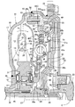
- FIG. 1 is a longitudinal sectional view of the torque converter according to the first embodiment.
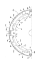
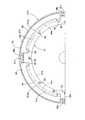
- FIG. 2 is a view of the damper mechanism as seen from the direction of arrows 2-2 in FIG.
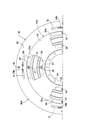
- FIG. 3 is a view of the dynamic damper mechanism as seen from the direction of arrows 3-3 in FIG.
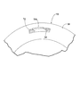
- FIG. 4 is a perspective view of the state in which the contact claw portion is inserted through the rotation restricting hole of the inertia plate as viewed from the lockup clutch side.
- FIG. 5 is a view showing the main part of FIG. 3 in a state where the relative rotation angle of the holding plate and the inertial rotating body is restricted.
- FIG. 5 is a view showing the main part of FIG. 3 in a state where the relative rotation angle of the holding plate and the inertial rotating body is restricted.
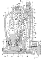
- FIG. 6 is a longitudinal sectional view of the torque converter according to the second embodiment.
- FIG. 7 is a longitudinal sectional view of the torque converter according to the third embodiment.
- FIG. 8 is a longitudinal sectional view of the torque converter of the fourth embodiment.
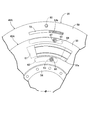
- FIG. 9 is a view of the damper mechanism as seen from the direction of arrows 9-9 in FIG. (Fourth embodiment)
- the torque converter includes a pump impeller 11 and a turbine runner disposed opposite to the pump impeller 11. 12 and a stator 13 disposed between the inner periphery of the pump impeller 11 and the turbine runner 12, as indicated by an arrow 14 between the pump impeller 11, the turbine runner 12 and the stator 13.
- a circulation circuit 15 for circulating the working oil is formed.
- the pump impeller 11 includes a bowl-shaped pump shell 16, a plurality of pump blades 17 provided on the inner surface of the pump shell 16, a pump core ring 18 that connects the pump blades 17, and an inner portion of the pump shell 16.
- a flange-shaped transmission cover 20 that covers the turbine runner 12 from the outside is joined to the outer periphery of the pump shell 16 by welding, and a ring gear 21 is fixed to the outer periphery of the transmission cover 20 by welding.
- a drive plate 22 is fastened to the ring gear 21.
- a crankshaft 23 of a vehicle engine E is coaxially fastened to the drive plate 22, and rotational power is input to the pump impeller 11 from the vehicle engine E.
- the turbine runner 12 has a bowl-shaped turbine shell 24, a plurality of turbine blades 25 provided on the inner surface of the turbine shell 24, and a turbine core ring 26 that connects the turbine blades 25.
- the end portion of the output shaft 27 that transmits the rotational power from the vehicle engine E to a transmission is connected to the bearing bush 28 on the bottomed cylindrical support cylinder portion 20a that the transmission cover 20 has integrally at the center thereof. Supported through.
- the output shaft 27 is spline-coupled to an output hub 29 disposed at a position spaced apart from the pump hub 19 in the axial direction, and a needle thrust bearing is provided between the output hub 29 and the transmission cover 20. 30 is interposed.
- the stator 13 includes a stator hub 31 disposed between the pump hub 19 and the output hub 29, a plurality of stator blades 32 provided on the outer periphery of the stator hub 31, and a stator core ring 33 that connects the outer periphery of the stator blades 32.
- a thrust bearing 34 is interposed between the pump hub 19 and the stator hub 31, and a thrust bearing 35 is interposed between the output hub 29 and the stator hub 31.
- a one-way clutch 37 is interposed between the stator hub 31 and a stator shaft 36 that surrounds the output shaft 27 that rotates together with the output hub 29 in a relatively rotatable manner. (Not shown) is supported in a non-rotatable manner.
- a clutch chamber 38 communicating with the circulation circuit 15 is formed between the transmission cover 20 and the turbine shell 24, and a lockup clutch 40 and an outer periphery of the output hub 29 are rotatable in the clutch chamber 38.
- the inertial rotating body 56 to be supported and the spring holder 42 ⁇ / b> A that sandwiches a part of the inertial rotating body 56 from both sides while allowing relative rotation within a limited range with respect to the inertial rotating body 56 are accommodated.
- the lockup clutch 40 has a clutch piston 43 that can be frictionally connected to the transmission cover 20 and switches between a connected state in which the clutch piston 43 is frictionally connected to the transmission cover 20 and a non-connected state in which the frictional connection is released.
- the inner periphery of the clutch piston 43 formed in a disc shape is supported by the output hub 29 so as to be axially movable and slidable.
- the clutch chamber 38 is partitioned by the clutch piston 43 into an inner chamber 38 a on the turbine runner 12 side and an outer chamber 38 b on the transmission cover 20 side, and is adjacent to the needle thrust bearing 30.
- An oil groove 44 formed in the output hub 29 communicates with the outer chamber 38 b, and the oil groove 44 communicates with the cylindrical output shaft 27.
- An oil passage 45 communicating with the inner periphery of the circulation circuit 15 is formed between the pump hub 19 and the stator shaft 36.
- the oil pump 44 and the oil reservoir (not shown) are alternately connected to the oil groove 44 and the oil passage 45.
- the pump impeller 11, the turbine runner 12, and the stator 13 circulate in the circulation circuit 15 in this order, and the rotational torque of the pump impeller 11 passes through the turbine runner 12, the spring holder 42 ⁇ / b> A, and the output hub 29 to the output shaft. 27.
- stator 13 In a state where a torque amplifying action is generated between the pump impeller 11 and the turbine runner 12, the accompanying reaction force is borne by the stator 13, and the stator 13 is fixed by the locking action of the one-way clutch 37. Further, when the torque amplification action is finished, the stator 13 rotates in the same direction together with the pump impeller 11 and the turbine runner 12 while idling the one-way clutch 37 by reversing the torque direction received by the stator 13.
- the damper mechanism 47 ⁇ / b> A is a plurality of damper mechanisms disposed at equal intervals in the circumferential direction between the spring holding member 51 fixed to the clutch piston 43 and the spring holder 42 ⁇ / b> A.
- the damper mechanism 47 ⁇ / b> A is a plurality of damper mechanisms disposed at equal intervals in the circumferential direction between the spring holding member 51 fixed to the clutch piston 43 and the spring holder 42 ⁇ / b> A.
- four coil-shaped damper springs 49 are interposed.
- An annular housing recess 50 is formed on the outer surface of the clutch piston 43 opposite to the transmission cover 20, and the damper is housed in the housing recess 50 at equal intervals in the circumferential direction.
- the spring holding member 51 that holds the spring 49 between the clutch piston 43 is fixed to the clutch piston 43.
- the spring holding member 51 has an outer periphery substantially corresponding to the inner periphery of the housing recess 50 and is disposed coaxially with the clutch piston 43, and the damper along the radial direction of the clutch piston 43. It is formed in a circular arc cross section so as to cover the inner side of the spring 49, and is continuously provided at four locations spaced at equal intervals in the circumferential direction of the outer periphery of the ring plate portion 51a and in the circumferential direction of the clutch piston 43.
- a spring cover portion 51b formed long along the spring cover portion 51b is disposed between the spring cover portions 51b and protrudes radially outward from the spring cover portion 51b on the outer periphery of the ring plate portion 51a.
- the ring plate portion 51 a is formed by a plurality of rivets 52 so as to integrally have a spring contact portion 51 c provided continuously. It is fixed to the Tchipisuton 43.
- the spring contact portion 51c is disposed between the four damper springs 49, and when the lock-up clutch 40 is in a disconnected state, the spring contact portion 51c is disposed on the dampers on both sides thereof. It contacts the end of the spring 49.
- the dynamic damper mechanism 48 ⁇ / b> A includes a spring holder 42 ⁇ / b> A that rotates together with the output hub 29 that is a rotation transmission member that constitutes a part of the torque transmission path 46 ⁇ / b> A, and an inertia rotating body 56.
- a plurality of, for example, six dynamic damper springs 57 having a coil shape are interposed therebetween.
- the spring holder 42A is composed of a pair of holding plates 54 and 55 that are connected to each other so as not to rotate relative to each other.
- the holding plates 54 and 55 are arranged at intervals in the axial direction of the output shaft 27 while rotating together with the output hub 29 which is a rotational transmission member constituting a part of the torque transmission path 46A.
- the holding plate 54 on the turbine runner 12 side is fixed to the output hub 29 by a plurality of rivets 53 together with the inner peripheral portion of the turbine shell 24 in the turbine runner 12.
- the inertia rotating body 56 is sandwiched between a pair of holding plates 54 and 55 constituting the spring holder 42A, and an inner peripheral portion is rotatably supported by the output hub 29. , And an additional weight member 59 fixed to the outer periphery of the inertia plate 58 with a rivet 60.
- Spring holding portions 54a and 55a for holding the dynamic damper spring 57 are provided at a plurality of places, for example, four places, at equal intervals in the circumferential direction of the holding plates 54 and 55. It is formed to face the outside.
- a portion of the inertia plate 58 corresponding to the spring holding portions 54a and 55a has a spring accommodation hole 61 for accommodating a part of the dynamic damper spring 57.
- the inertia plate 58 is formed so that both end portions of the spring accommodating hole 61 along the circumferential direction 58 are in contact with both end portions of the dynamic damper spring 57.
- the inertia plate 58 is formed such that an outer peripheral portion thereof protrudes radially outward from the holding plates 54 and 55, and the additional weight member 59 is fixed to the outer peripheral portion of the inertia plate 58.
- a plurality of locations for example, four spaced apart in the circumferential direction of the inertial plate 58.
- Cylindrical spacers 63 that are respectively inserted into the long holes 62 provided in the places are interposed, and a pair of the holding plates is provided on the outer side of the spring accommodating hole 61 along the radial direction of the inertial rotating body 56.
- Cylindrical spacers 65 are inserted between the long holes 64 provided at a plurality of locations, for example, at four locations spaced at equal intervals in the circumferential direction of the inertia plate 58.
- the holding plates 54 and 55 are connected by rivets 66 and 67 that penetrate the spacers 63 and 65, respectively. That is, the inertia plate 58 can rotate relative to the spring holder 42A within a limited range in which the spacers 63 and 64 move within the long holes 62 and 64.
- One of the pair of holding plates 54 and 55 constituting the spring holder 42A in this embodiment, the holding plate 54 on the side opposite to the clutch piston 43 of the lockup clutch 40 of the holding plates 54 and 55 is provided on the holding plate 54.
- a plurality of contact claw portions 54b that sandwich the damper spring 49 with the spring contact portion 51c of the spring holding member 51 are integrally provided, and the damper mechanism 47A is connected to the clutch piston 43.
- a damper spring 49 is interposed between the spring contact portion 51c of the spring holding member 51 to be fixed and the contact claw portion 54b of the holding plate 54 in the spring holder 42A.
- the four contact claws 54b which is the same number as the number of the damper springs 49, are bent so as to swell from the outer periphery of the holding plate 54 to the side opposite to the damper springs 49, and the bent It is integrally provided on the holding plate 54 so as to extend in a direction along the axis of the output shaft 27 from the portion.
- the plate thickness of the holding plate 54 on the side where the contact claw portion 54 b is provided in the pair of holding plates 54 and 55 is set to be larger than the plate thickness of the other holding plate 55.
- the spring holding member 51 fixed to the clutch piston 43 is formed with a plurality of notches 70 arranged between the plurality of spring cover portions 51b.
- the claw portion 54 b is inserted through the notch portion 70.
- the notches 70 are formed at a plurality of, for example, four places that are long in the circumferential direction and are equally spaced in the circumferential direction of the spring holding member 51 so as to open to the front end side of the spring cover 51b. Moreover, the notch 70 is arranged such that the inner end 70a of the notch 70 along the radial direction of the output shaft 27 is located outward from the inner end 49a of the damper spring 49 in the radial direction.
- the spring holding member 51 is formed. That is, as shown in FIG. 1, on the projection onto the plane passing through the axis of the contact claw 54 b and the output shaft 27, it passes through the inner end 49 a of the damper spring 49 and is parallel to the axis of the output shaft 27.
- the inner end 70a of the cutout portion 70 is disposed at an outer position along the radial direction with respect to an imaginary straight line L extending in the vertical direction.
- the spring contact portion 51c is disposed so as to be located at the center in the circumferential direction of the notch portion 70 when viewed from the spring holder 42A side, and both sides of the base portion of the spring contact portion 51c.
- a recess 71 for forming the spring cover portion 51b in an arc shape in cross section so as to cover the damper spring 49 is formed to be continuous with the notch portion 70.
- the contact claw portion 54 b is a part of the contact claw portion 54 b on the projection view on the plane passing through the axis of the contact claw portion 54 b and the output shaft 27.
- a rotation restricting hole 72 extending in the circumferential direction is formed in the inertia plate 58, as shown in FIGS.
- the contact claw portion 54 b is inserted into the rotation restriction hole 72 so that a part of the contact claw part 54 b is accommodated in the rotation restriction hole 72.
- the rotation restricting hole 72 has a pair of the holding plates 54 and 55 and the inertia as a result of the contact pawl portion 54b coming into contact with the circumferential end of the rotation restricting hole 72. It is formed so as to regulate the relative rotation angle of the rotating body 56.
- the damper mechanism 47A has a plurality of damper springs 49 and a circular arc cross section so that the damper springs 49 are held between the clutch pistons 43.
- a pair of spring holding members 51 that are fixed to the clutch piston 43 while having a plurality of spring cover portions 51b formed on the same, and a part of the dynamic damper mechanism 48A that sandwich the inertia plate 58 of the inertia rotating body 56.
- a plurality of contact claw portions 54b sandwiching the damper spring 49 with the spring holding member 51, and the contact claw portions 54b are inserted therethrough.
- the radial direction of the output shaft 27 of the notch 70 formed in the spring holding member 51 is along.
- the end 70a is disposed outward from the inner end 49a of the damper spring 49 in the radial direction, and the contact claw portion 54b is in a plane passing through the contact claw portion 54b and the axis of the output shaft 27. Is formed so that a part of the contact claw portion 54b overlaps the inertia plate 58, so that the contact claw portion 54b can avoid the interference with the spring cover portion 51b and the radius of the output shaft 27 can be avoided. It is possible to dispose the damper spring 49 to the outer side in the direction, and to reduce the axial distance between the clutch piston 43 and the dynamic damper mechanism 48A while maintaining the holding function of the damper spring 49 by the spring holding member 51. Become.
- the abutment claw portion 54b is provided integrally with the holding plate 54 of the pair of holding plates 54, 55 opposite to the clutch piston 43 of the lockup clutch 40, and the clutch piston 43 and the dynamic damper.
- the axial distance between the mechanisms 48A can be further shortened.
- the tip of the abutment claw 54b passes through the center C of the damper spring 49 or is disposed at a position outward from the center C of the output shaft 27 in the radial direction.
- the damper spring 49 is compressed, the damper spring 49 is prevented from bending so as to bulge outward in the radial direction of the output shaft 27, and a frictional force is generated by the frictional contact between the damper spring 49 and the clutch piston 43. Can be suppressed.
- the inertia plate 58 accommodates a part of the contact claw portion 54 b and extends in the circumferential direction so that the rotation restriction hole 72 extends to the circumferential end of the rotation restriction hole 72. Since the relative rotation angle between the pair of holding plates 54 and 55 and the inertial rotating body 56 is regulated by the contact, the relative rotation angle between the pair of holding plates 54 and 55 and the inertial rotating body 56 can be simplified. Therefore, it is possible to prevent an excessive load from being applied to the dynamic damper spring 57 of the dynamic damper mechanism 48A.
- the torque transmission path 46B is provided with at least one (in this embodiment, one) damper mechanism 47B and a dynamic damper mechanism 48B.
- the damper mechanism 47B includes a plurality of, for example, four coil-shaped dampers arranged at equal intervals in the circumferential direction between the spring holding member 51 fixed to the clutch piston 43 and the spring holder 42B.
- a spring 49 is interposed.
- the dynamic damper mechanism 48B includes a plurality of, for example, six coils between a spring holder 42B that rotates together with the output hub 29 that is a rotational transmission member that constitutes a part of the torque transmission path 46B, and the inertia rotating body 56.
- a dynamic damper spring 57 having a shape is interposed.
- the spring holder 42B includes a pair of holding plates 74 and 75 that are connected to each other so as not to be relatively rotatable.
- the holding plates 74 and 75 constitute a part of the torque transmission path 46B. While being rotated together with the output hub 29 which is a rotation transmission member, the output shaft 27 is arranged at an interval in the axial direction.
- the holding plate 74 on the turbine runner 12 side of the pair of holding plates 74 and 75 is fixed to the output hub 29 by a plurality of rivets 53 together with the inner peripheral portion of the turbine shell 24 in the turbine runner 12.
- the inertia rotating body 56 is sandwiched between a pair of holding plates 74 and 75 constituting the spring holder 42B, and an inner peripheral portion is rotatably supported by the output hub 29. And an additional weight member 59 fixed to the outer periphery of the inertia plate 58.
- Spring holding parts 74a and 75a for holding the dynamic damper spring 57 are provided at a plurality of places, for example, four places, at equal intervals in the circumferential direction of the holding plates 74 and 75. It is formed to face the outside.
- a portion of the inertia plate 58 corresponding to the spring holding portions 74a and 75a has a spring accommodation hole 61 for accommodating a part of the dynamic damper spring 57.
- the inertia plate 58 is formed so that both end portions of the spring accommodating hole 61 along the circumferential direction 58 are in contact with both end portions of the dynamic damper spring 57.
- a plurality of locations for example, 4 spaced apart at equal intervals in the circumferential direction of the inertial plate 58.
- Cylindrical spacers 63 that are respectively inserted into the long holes 62 provided in the places are interposed, and the holding plates 74 and 75 are connected by a rivet 66 that penetrates the spacer 63.
- the holding plate 74 on the opposite side of the lock-up clutch 40 from the clutch piston 43 is included in the holding plate 74 and 75.
- the damper spring 49 is inserted into the notch portion 70 formed in the spring holding member 51 fixed to the clutch piston 43 so as to sandwich the damper spring 49 between the spring holding portion 51c of the spring holding member 51.
- a plurality of abutting claw portions 74b are integrally provided, and the damper mechanism 47B is configured to abut the spring abutting portion 51c of the spring holding member 51 fixed to the clutch piston 43 and the holding plate 74 in the spring holder 42B.
- a damper spring 49 is interposed between the claw portions 74b.
- the plate thickness of the holding plate 74 on the side where the contact claw portion 74b is provided in the pair of holding plates 74 and 75 is set larger than the plate thickness of the other holding plate 75.
- the contact claw portion 74b is bent so that a part of the contact claw portion 74b overlaps the inertia plate 58 on a projection view on a plane passing through the corresponding contact claw portion 74b and the axis of the output shaft 27.
- the inertia plate 58 is formed with a rotation restricting hole 76 that extends long in the circumferential direction, and a part of the contact claw portion 74b is the rotation restricting hole.
- the rotation restricting hole 76 is inserted so as to be accommodated in 76.
- the other of the pair of holding plates 74 and 75 that is, a part of the holding plate 75 is disposed in the rotation restricting hole 76 and abutted and fixed to the contact claw portion 74b.
- a mounting plate portion 75 b that is integrally connected to the outer periphery of the holding plate 75 and is disposed in the rotation restricting hole 76 is disposed in the rotation restricting hole 76 and is in contact with the contact claw. It abuts on the portion 74 b and is caulked and fixed to the abutment claw portion 74 b with a rivet 77.
- the same effect as that of the first embodiment can be obtained, and the pair of holding plates 74 can be provided on the outer side of the dynamic damper spring 57 in the radial direction of the output shaft 27. , 75 is not required, and a spacer arranged so as to be interposed between the two holding plates 74, 75 is not necessary, and the cost can be reduced.
- torque transmitted from the vehicle engine E to the transmission cover 20 passes through the torque transmission path 46C including the clutch piston 43, the spring holder 42C and the output hub 29 to the output shaft 27.
- the torque transmission path 46C is provided with at least one (one in this embodiment) damper mechanism 47C and a dynamic damper mechanism 48C.
- the damper mechanism 47C includes a plurality of, for example, four coil-shaped dampers arranged at equal intervals in the circumferential direction between the spring holding member 51 fixed to the clutch piston 43 and the spring holder 42C.
- a spring 49 is interposed.
- the dynamic damper mechanism 48C includes a plurality of, for example, six coils between the spring holder 42C that rotates together with the output hub 29 that is a rotation transmission member that constitutes a part of the torque transmission path 46C, and the inertia rotating body 56.
- a dynamic damper spring 57 having a shape is interposed.
- the spring holder 42C includes a pair of holding plates 84 and 85 that constitute a part of the torque transmission path 46C, and the holding plates 84 and 85 constitute a part of the torque transmission path 46C.
- the output shaft 27 is arranged with an interval in the axial direction while rotating together with the output hub 29 which is a rotational transmission member.
- the holding plate 84 on the turbine runner 12 side of the pair of holding plates 84 and 85 is fixed to the output hub 29 by a plurality of rivets 53 together with the inner peripheral portion of the turbine shell 24 in the turbine runner 12.
- the inertia rotator 56 is sandwiched between a pair of the holding plates 84 and 85 constituting the spring holder 42C, and an inner peripheral portion is rotatably supported by the output hub 29. And an additional weight member 59 fixed to the outer periphery of the inertia plate 58.
- Spring holding portions 84a and 85a for holding the dynamic damper spring 57 are provided at a plurality of, for example, four places at equal intervals in the circumferential direction of the holding plates 84 and 85. It is formed to face the outside.
- a portion of the inertia plate 58 corresponding to the spring holding portions 84a and 85a has a spring accommodation hole 61 for accommodating a part of the dynamic damper spring 57.
- the inertia plate 58 is formed so that both end portions of the spring accommodating hole 61 along the circumferential direction 58 are in contact with both end portions of the dynamic damper spring 57.
- a plurality of locations for example, 4 spaced at equal intervals in the circumferential direction of the inertial plate 58.
- Cylindrical spacers 63 that are respectively inserted into the long holes 62 provided in the places are interposed, and a pair of the holding plates is provided on the outer side of the spring accommodating hole 61 along the radial direction of the inertial rotating body 56.
- Cylindrical spacers 65 that are respectively inserted into a plurality of long holes 64 provided at a plurality of, for example, four places at equal intervals in the circumferential direction of the inertia plate 58 are interposed between the 84 and 85.
- the holding plates 84 and 85 are connected by rivets 66 and 67 that penetrate the spacers 63 and 65.
- the holding plate 85 on the clutch piston 43 side of the lock-up clutch 40 of the holding plates 84 and 85 is included in the clutch.
- the damper spring 49 is inserted into a notch portion 70 formed in the spring holding member 51 fixed to the piston 43 so as to sandwich the damper spring 49 between the spring abutting portion 51 c of the spring holding member 51.
- a contact claw portion 85b is integrally provided, and the damper mechanism 47C includes a spring contact portion 51c of a spring holding member 51 fixed to the clutch piston 43 and a contact claw portion 85b of the holding plate 85 in the spring holder 42C.
- a damper spring 49 is interposed therebetween.
- the plate thickness of the holding plate 85 on the side of the pair of holding plates 84 and 85 where the contact claw portion 85b is provided is set to be larger than the plate thickness of the other holding plate 84.
- the contact claw portion 85b is bent so that a part of the contact claw portion 85b overlaps the inertia plate 58 on a projection view on a plane passing through the corresponding contact claw portion 85b and the axis of the output shaft 27.
- a rotation restricting hole 86 extending in the circumferential direction is formed in the inertia plate 58, and a part of the contact claw 85b is formed in the rotation restricting hole 86.
- the contact claw portion 85b is integrally provided on the holding plate 85 on the clutch piston 43 side of the lock-up clutch 40 of the pair of holding plates 84 and 85.
- the axial distance between the clutch piston 43 and the dynamic damper mechanism 48C can be shortened while maintaining the function of holding the damper spring 49 by the spring holding member 51.
- a fourth embodiment of the present invention will be described with reference to FIG. 8 and FIG. 9, but the portions corresponding to the first to third embodiments are only shown with the same reference numerals. Detailed description will be omitted.
- the torque transmission path 46A including the clutch piston 43, the spring holder 42A and the output hub 29 to the output shaft 27.
- the torque transmission path 46A is provided with at least one (one in this embodiment) damper mechanism 47D and a dynamic damper mechanism 48A.
- the damper mechanism 47D includes a plurality of, for example, four coil-shaped dampers arranged at equal intervals in the circumferential direction between a spring holding member 91 fixed to the clutch piston 43 and the spring holder 42A.
- a spring 49 is interposed.
- An annular housing recess 50 is formed on the outer surface of the clutch piston 43 opposite to the transmission cover 20, and the damper is housed in the housing recess 50 at equal intervals in the circumferential direction.
- the spring holding member 91 that holds the spring 49 between the clutch piston 43 is fixed to the clutch piston 43.
- the spring holding member 91 has an outer periphery substantially corresponding to the inner periphery of the housing recess 50 and is disposed coaxially with the clutch piston 43, and the damper along the radial direction of the clutch piston 43.
- a circular cross section is formed so as to cover the inner side of the spring 49, and is continuously provided at four locations at equal intervals in the circumferential direction of the outer periphery of the ring plate portion 91 a and in the circumferential direction of the clutch piston 43.
- a spring cover portion 91b that is formed along the length of the ring plate portion 91b.
- the spring cover portion 91b is disposed between the spring cover portions 91b and protrudes radially outward from the spring cover portion 91b.
- the ring plate portion 91a is formed by a plurality of rivets 52 so as to have a spring contact portion 91c provided continuously. It is fixed to the Tchipisuton 43.
- the spring abutting portion 91c is disposed between the four damper springs 49, and when the lock-up clutch 40 is in a disconnected state, the spring abutting portion 91c It contacts the end of the spring 49.
- the holding plate 54 is integrally provided with a plurality of contact claw portions 54 b that sandwich the damper spring 49 with the spring contact portion 91 c of the spring holding member 91.
- the spring cover portion 91b is formed so that at least a part of the spring cover portion 91b is positioned outward from the inner end 49a of the damper spring 49 in the radial direction of the output shaft 27.
- the outer end 91ba of the spring cover portion 91b along the radial direction is located at an outer position along the radial direction, and the contact claw portion 54b is formed of the spring cover portion along the radial direction. It can abut against the damper spring 49 outside 91b.
- concave portions 92 are formed so as to cover the damper spring 49 and to form the spring cover portion 91b in a cross-sectional arc shape.
- the contact claw portion 54b is configured such that a part of the contact claw portion 54b overlaps the inertia plate 58 on a projection view on a plane passing through the contact claw portion 54b and the axis of the output shaft 27.
- a part of the contact claw 54b is accommodated in the rotation restricting hole 72 formed in the inertia plate 58 so as to extend long in the circumferential direction. It is inserted like this.
- the spring holding member 91 does not have a function of restricting the circumferential relative position of the contact claw portion 54b with respect to the clutch piston 43, the damper spring 49 is brought into a close contact state in the axial direction thereof.
- the relative position in the circumferential direction of the abutment claw portion 54b with respect to the piston 43 is restricted, and there is an advantage that the spring holding member 91 is not required to have a large strength and the spring holding member 91 can be made thin.
- the axial distance between the clutch piston 43 and the dynamic damper mechanism 48A while maintaining the holding function of the damper spring 49 by the spring holding member 91, as in the first embodiment. Can be shortened.
Landscapes
- Engineering & Computer Science (AREA)
- General Engineering & Computer Science (AREA)
- Mechanical Engineering (AREA)
- Physics & Mathematics (AREA)
- Acoustics & Sound (AREA)
- Aviation & Aerospace Engineering (AREA)
- Mechanical Operated Clutches (AREA)
- Hydraulic Clutches, Magnetic Clutches, Fluid Clutches, And Fluid Joints (AREA)
Abstract
L'invention concerne un convertisseur de couple dans lequel des saillies de contact disposées intégralement sur l'une d'une paire de plaques de retenue qui constituent des parties d'un mécanisme amortisseur dynamique sont insérées à travers les découpes d'un élément de retenue de ressort fixé à un piston d'embrayage. Les découpes (70) sont formées de telle sorte que les extrémités intérieures (70a) des découpes (70) s'étendant dans la direction radiale d'un arbre de sortie (27) soient situées à l'extérieur, dans la direction radiale, des extrémités intérieures (49a) de ressorts amortisseurs (49). Les saillies de contact (54b) sont chacune formées de telle sorte qu'une partie de la saillie de contact (54b) chevauche une plaque d'inertie (58) dans une vue projetée sur un plan passant à travers la saillie de contact (54b) et l'axe de l'arbre de sortie (27). En conséquence, la distance axiale entre le piston d'embrayage et le mécanisme amortisseur dynamique peut être réduite tandis que la fonction de retenue de ressort amortisseur de l'élément de retenue de ressort est maintenue.
Priority Applications (2)
| Application Number | Priority Date | Filing Date | Title |
|---|---|---|---|
| CN201780028102.6A CN109154373B (zh) | 2015-10-30 | 2017-03-16 | 变矩器 |
| US16/090,950 US10683908B2 (en) | 2015-10-30 | 2017-03-16 | Torque converter |
Applications Claiming Priority (3)
| Application Number | Priority Date | Filing Date | Title |
|---|---|---|---|
| JP2015213855 | 2015-10-30 | ||
| JP2016077970A JP6345200B2 (ja) | 2015-10-30 | 2016-04-08 | トルクコンバータ |
| JP2016-077970 | 2016-04-08 |
Publications (1)
| Publication Number | Publication Date |
|---|---|
| WO2017175557A1 true WO2017175557A1 (fr) | 2017-10-12 |
Family
ID=58712929
Family Applications (1)
| Application Number | Title | Priority Date | Filing Date |
|---|---|---|---|
| PCT/JP2017/010597 WO2017175557A1 (fr) | 2015-10-30 | 2017-03-16 | Convertisseur de couple |
Country Status (4)
| Country | Link |
|---|---|
| US (1) | US10683908B2 (fr) |
| JP (1) | JP6345200B2 (fr) |
| CN (1) | CN109154373B (fr) |
| WO (1) | WO2017175557A1 (fr) |
Families Citing this family (5)
| Publication number | Priority date | Publication date | Assignee | Title |
|---|---|---|---|---|
| US11767899B2 (en) | 2019-06-12 | 2023-09-26 | Yutaka Giken Co., Ltd. | Power transmission device |
| JP7215983B2 (ja) * | 2019-09-25 | 2023-01-31 | 株式会社ユタカ技研 | 動力伝達装置 |
| JP2020200908A (ja) * | 2019-06-12 | 2020-12-17 | 株式会社ユタカ技研 | 動力伝達装置 |
| JP7451307B2 (ja) | 2020-06-01 | 2024-03-18 | 株式会社エクセディ | ロックアップ装置 |
| JP7303230B2 (ja) * | 2021-02-08 | 2023-07-04 | 株式会社ユタカ技研 | ダイナミックダンパ付き伝動装置及びトルクコンバータ |
Citations (3)
| Publication number | Priority date | Publication date | Assignee | Title |
|---|---|---|---|---|
| JP2007113659A (ja) * | 2005-10-19 | 2007-05-10 | Exedy Corp | 流体式トルク伝達装置およびそれに用いられるロックアップ装置 |
| JP2009115112A (ja) * | 2007-11-01 | 2009-05-28 | Honda Motor Co Ltd | 流体伝動装置 |
| WO2015005379A1 (fr) * | 2013-07-11 | 2015-01-15 | 株式会社エクセディ | Dispositif de verrouillage pour convertisseur de couple |
Family Cites Families (9)
| Publication number | Priority date | Publication date | Assignee | Title |
|---|---|---|---|---|
| JP4648428B2 (ja) | 2008-06-03 | 2011-03-09 | 株式会社エクセディ | 流体式動力伝達装置 |
| EP2644944B1 (fr) * | 2010-11-24 | 2019-06-05 | Toyota Jidosha Kabushiki Kaisha | Dispositif de transmission de puissance pour véhicule |
| JP5418531B2 (ja) * | 2011-03-28 | 2014-02-19 | アイシン・エィ・ダブリュ株式会社 | ダンパ装置 |
| US9732824B2 (en) * | 2013-01-30 | 2017-08-15 | Aisin Aw Co., Ltd. | Damper device and starting device |
| JP5684846B2 (ja) * | 2013-03-21 | 2015-03-18 | 株式会社エクセディ | トルクコンバータのロックアップ装置 |
| JP6110192B2 (ja) * | 2013-04-11 | 2017-04-05 | 株式会社エクセディ | トルクコンバータのロックアップ装置 |
| JP5734365B2 (ja) * | 2013-06-04 | 2015-06-17 | 株式会社エクセディ | トルクコンバータのロックアップ装置 |
| US9534641B2 (en) * | 2014-02-28 | 2017-01-03 | Schaeffler Technologies AG & Co. KG | Folded seal retention plate with thrust surface |
| JP5791773B1 (ja) * | 2014-08-29 | 2015-10-07 | 株式会社エクセディ | 流体式動力伝達装置 |
-
2016
- 2016-04-08 JP JP2016077970A patent/JP6345200B2/ja active Active
-
2017
- 2017-03-16 CN CN201780028102.6A patent/CN109154373B/zh not_active Expired - Fee Related
- 2017-03-16 US US16/090,950 patent/US10683908B2/en active Active
- 2017-03-16 WO PCT/JP2017/010597 patent/WO2017175557A1/fr active Application Filing
Patent Citations (3)
| Publication number | Priority date | Publication date | Assignee | Title |
|---|---|---|---|---|
| JP2007113659A (ja) * | 2005-10-19 | 2007-05-10 | Exedy Corp | 流体式トルク伝達装置およびそれに用いられるロックアップ装置 |
| JP2009115112A (ja) * | 2007-11-01 | 2009-05-28 | Honda Motor Co Ltd | 流体伝動装置 |
| WO2015005379A1 (fr) * | 2013-07-11 | 2015-01-15 | 株式会社エクセディ | Dispositif de verrouillage pour convertisseur de couple |
Also Published As
| Publication number | Publication date |
|---|---|
| US20190120322A1 (en) | 2019-04-25 |
| JP6345200B2 (ja) | 2018-06-20 |
| CN109154373A (zh) | 2019-01-04 |
| CN109154373B (zh) | 2021-06-18 |
| US10683908B2 (en) | 2020-06-16 |
| JP2017083004A (ja) | 2017-05-18 |
Similar Documents
| Publication | Publication Date | Title |
|---|---|---|
| WO2017175557A1 (fr) | Convertisseur de couple | |
| JP5685304B2 (ja) | トルクコンバータのロックアップ装置 | |
| KR101803952B1 (ko) | 차량용 토크 컨버터 | |
| JP6269244B2 (ja) | ダンパ装置 | |
| JP5832472B2 (ja) | トルクダンパ装置 | |
| JP2015014360A (ja) | ダンパ装置及びトルクコンバータのロックアップ装置 | |
| JP6182434B2 (ja) | トルクコンバータのロックアップ装置 | |
| JP5407947B2 (ja) | ダンパ装置および流体伝動装置 | |
| WO2018155357A1 (fr) | Convertisseur de couple | |
| JP2003269573A (ja) | ピストン連結機構及びそれを備えた流体式トルク伝達装置のロックアップ装置 | |
| JP4073749B2 (ja) | 流体式トルク伝達装置のロックアップ装置 | |
| JP2006162054A5 (fr) | ||
| JP6636972B2 (ja) | トルクコンバータ | |
| JP6660331B2 (ja) | トルクコンバータ | |
| JP2007132522A (ja) | 流体式トルク伝達装置のロックアップ装置 | |
| JP6161047B2 (ja) | トルクコンバータ | |
| JP5986868B2 (ja) | クラッチ | |
| JP6976775B2 (ja) | トルクコンバータ | |
| JP2003269575A (ja) | 流体式トルク伝達装置のロックアップ装置 | |
| JP6263801B2 (ja) | トルクコンバータ | |
| WO2020158174A1 (fr) | Dispositif de démarrage | |
| JP6360714B2 (ja) | トルクコンバータのロックアップ装置 | |
| JP2014055642A (ja) | トルクコンバータのロックアップ装置 | |
| JP2011196489A (ja) | ロックアップクラッチ装置 | |
| JP2011208750A (ja) | エンジンのフライホイール装置及びその製造方法 |
Legal Events
| Date | Code | Title | Description |
|---|---|---|---|
| NENP | Non-entry into the national phase |
Ref country code: DE |
|
| 121 | Ep: the epo has been informed by wipo that ep was designated in this application |
Ref document number: 17778936 Country of ref document: EP Kind code of ref document: A1 |
|
| 122 | Ep: pct application non-entry in european phase |
Ref document number: 17778936 Country of ref document: EP Kind code of ref document: A1 |