WO2017175325A1 - 電動パワーステアリング装置 - Google Patents
電動パワーステアリング装置 Download PDFInfo
- Publication number
- WO2017175325A1 WO2017175325A1 PCT/JP2016/061211 JP2016061211W WO2017175325A1 WO 2017175325 A1 WO2017175325 A1 WO 2017175325A1 JP 2016061211 W JP2016061211 W JP 2016061211W WO 2017175325 A1 WO2017175325 A1 WO 2017175325A1
- Authority
- WO
- WIPO (PCT)
- Prior art keywords
- housing
- phase
- control unit
- winding
- power steering
- Prior art date
Links
Images


Classifications
-
- B—PERFORMING OPERATIONS; TRANSPORTING
- B62—LAND VEHICLES FOR TRAVELLING OTHERWISE THAN ON RAILS
- B62D—MOTOR VEHICLES; TRAILERS
- B62D5/00—Power-assisted or power-driven steering
- B62D5/04—Power-assisted or power-driven steering electrical, e.g. using an electric servo-motor connected to, or forming part of, the steering gear
- B62D5/0403—Power-assisted or power-driven steering electrical, e.g. using an electric servo-motor connected to, or forming part of, the steering gear characterised by constructional features, e.g. common housing for motor and gear box
- B62D5/0406—Power-assisted or power-driven steering electrical, e.g. using an electric servo-motor connected to, or forming part of, the steering gear characterised by constructional features, e.g. common housing for motor and gear box including housing for electronic control unit
-
- H—ELECTRICITY
- H02—GENERATION; CONVERSION OR DISTRIBUTION OF ELECTRIC POWER
- H02K—DYNAMO-ELECTRIC MACHINES
- H02K11/00—Structural association of dynamo-electric machines with electric components or with devices for shielding, monitoring or protection
- H02K11/30—Structural association with control circuits or drive circuits
- H02K11/33—Drive circuits, e.g. power electronics
-
- H—ELECTRICITY
- H02—GENERATION; CONVERSION OR DISTRIBUTION OF ELECTRIC POWER
- H02K—DYNAMO-ELECTRIC MACHINES
- H02K3/00—Details of windings
- H02K3/46—Fastening of windings on the stator or rotor structure
- H02K3/50—Fastening of winding heads, equalising connectors, or connections thereto
-
- H—ELECTRICITY
- H02—GENERATION; CONVERSION OR DISTRIBUTION OF ELECTRIC POWER
- H02K—DYNAMO-ELECTRIC MACHINES
- H02K5/00—Casings; Enclosures; Supports
- H02K5/04—Casings or enclosures characterised by the shape, form or construction thereof
-
- H—ELECTRICITY
- H02—GENERATION; CONVERSION OR DISTRIBUTION OF ELECTRIC POWER
- H02K—DYNAMO-ELECTRIC MACHINES
- H02K5/00—Casings; Enclosures; Supports
- H02K5/04—Casings or enclosures characterised by the shape, form or construction thereof
- H02K5/22—Auxiliary parts of casings not covered by groups H02K5/06-H02K5/20, e.g. shaped to form connection boxes or terminal boxes
- H02K5/225—Terminal boxes or connection arrangements
-
- B—PERFORMING OPERATIONS; TRANSPORTING
- B62—LAND VEHICLES FOR TRAVELLING OTHERWISE THAN ON RAILS
- B62D—MOTOR VEHICLES; TRAILERS
- B62D5/00—Power-assisted or power-driven steering
- B62D5/04—Power-assisted or power-driven steering electrical, e.g. using an electric servo-motor connected to, or forming part of, the steering gear
- B62D5/0457—Power-assisted or power-driven steering electrical, e.g. using an electric servo-motor connected to, or forming part of, the steering gear characterised by control features of the drive means as such
- B62D5/046—Controlling the motor
- B62D5/0463—Controlling the motor calculating assisting torque from the motor based on driver input
-
- H—ELECTRICITY
- H02—GENERATION; CONVERSION OR DISTRIBUTION OF ELECTRIC POWER
- H02K—DYNAMO-ELECTRIC MACHINES
- H02K11/00—Structural association of dynamo-electric machines with electric components or with devices for shielding, monitoring or protection
- H02K11/20—Structural association of dynamo-electric machines with electric components or with devices for shielding, monitoring or protection for measuring, monitoring, testing, protecting or switching
- H02K11/21—Devices for sensing speed or position, or actuated thereby
-
- H—ELECTRICITY
- H02—GENERATION; CONVERSION OR DISTRIBUTION OF ELECTRIC POWER
- H02K—DYNAMO-ELECTRIC MACHINES
- H02K11/00—Structural association of dynamo-electric machines with electric components or with devices for shielding, monitoring or protection
- H02K11/20—Structural association of dynamo-electric machines with electric components or with devices for shielding, monitoring or protection for measuring, monitoring, testing, protecting or switching
- H02K11/24—Devices for sensing torque, or actuated thereby
-
- H—ELECTRICITY
- H02—GENERATION; CONVERSION OR DISTRIBUTION OF ELECTRIC POWER
- H02P—CONTROL OR REGULATION OF ELECTRIC MOTORS, ELECTRIC GENERATORS OR DYNAMO-ELECTRIC CONVERTERS; CONTROLLING TRANSFORMERS, REACTORS OR CHOKE COILS
- H02P25/00—Arrangements or methods for the control of AC motors characterised by the kind of AC motor or by structural details
- H02P25/16—Arrangements or methods for the control of AC motors characterised by the kind of AC motor or by structural details characterised by the circuit arrangement or by the kind of wiring
- H02P25/22—Multiple windings; Windings for more than three phases
-
- H—ELECTRICITY
- H02—GENERATION; CONVERSION OR DISTRIBUTION OF ELECTRIC POWER
- H02P—CONTROL OR REGULATION OF ELECTRIC MOTORS, ELECTRIC GENERATORS OR DYNAMO-ELECTRIC CONVERTERS; CONTROLLING TRANSFORMERS, REACTORS OR CHOKE COILS
- H02P27/00—Arrangements or methods for the control of AC motors characterised by the kind of supply voltage
- H02P27/04—Arrangements or methods for the control of AC motors characterised by the kind of supply voltage using variable-frequency supply voltage, e.g. inverter or converter supply voltage
- H02P27/06—Arrangements or methods for the control of AC motors characterised by the kind of supply voltage using variable-frequency supply voltage, e.g. inverter or converter supply voltage using dc to ac converters or inverters
Definitions
- the present invention relates to an electric power steering device for a vehicle, and more particularly to an electric power steering device in which a motor and a control unit are integrated.
- an electric power steering device generates an auxiliary torque corresponding to a steering torque applied by a driver to a steering system of a vehicle by an electric motor, and adds the auxiliary torque to the steering system to assist the steering of the driver.
- an electric power steering apparatus having two sets of armature windings of the same configuration in an electric motor and two control circuit inverter circuits that can independently drive the two sets of armature windings has been put into practical use. ing.
- Such an electric power steering device controls two sets of inverter circuits in cooperation, and when an abnormality occurs in a control system including one inverter circuit, only the control system including the other normal inverter circuit is used. The driving of the electric motor is continued to prevent the vehicle from becoming unsteerable and ensure the safety of the vehicle.
- the electric motor and the control unit are arranged coaxially on the axis of the output shaft of the electric motor, and the control unit is arranged on the non-output side of the electric motor,
- the structure which integrated the electric motor and the control unit is disclosed (for example, refer patent document 1).
- the conventional electric power steering device disclosed in Patent Document 1 is an inverter in a control unit in which six winding end portions of two sets of armature windings of an electric motor are collectively extended from the electric motor into the control unit. Connected to the department. And the connection location of a coil
- the power supply system connector is arranged near the center of the cover that covers the control unit, and the capacitor, choke coil, stator winding end, etc. connected to the power supply system connector are located inside the cover of the control unit. Arranged in space.
- the inner space of the cover of the control unit is the winding end of the armature winding, the capacitor, and the choke coil. Large areas such as these occupy a large area, which hinders miniaturization of the electric power steering apparatus.
- the present invention has been made to solve the above-mentioned problems in the conventional electric power steering apparatus, and provides an electric power steering apparatus that can be miniaturized by optimizing the arrangement of components.
- the purpose is to do.
- the electric power steering device is: An electric motor having two sets of armature windings of the same configuration and generating an assist torque corresponding to a steering torque by a vehicle driver; It has two sets of control circuit units capable of individually controlling the two sets of armature windings, and is arranged at an end portion in the axial direction on the non-output side of the electric motor and fixed integrally with the electric motor.
- the control unit is A power connector for connecting the control unit and an external power source; A first connecting portion that connects a winding terminal of one armature winding of the two sets of armature windings and one control circuit portion of the two sets of control circuit portions; A second connecting portion for connecting a winding terminal of the other armature winding of the two sets of armature windings and the other control circuit portion of the two sets of control circuit portions;
- the power connector is fixed to the housing at or near the radial center of the housing.
- the first connection portion and the second connection portion are disposed substantially symmetrically at a position corresponding to the peripheral portion in the radial direction of the power connector. It is characterized by that.
- the control unit includes a power supply connector for connecting the control unit and an external power supply, and a winding terminal of one armature winding of the two sets of armature windings.
- a first connection portion that connects one control circuit portion of the two sets of control circuit portions, a winding terminal of the other armature winding of the two sets of armature windings, and two sets of A second connecting portion that connects the other control circuit portion of the control circuit portions, and the power connector is fixed to the housing at or near the central portion in the radial direction of the housing.
- the connecting portion and the second connecting portion are arranged so as to be substantially symmetrical at positions corresponding to the peripheral portion in the radial direction of the power connector, all parts of the control unit are arranged in the motor. It can arrange
- FIG. 1 is a cross-sectional view of an electric power steering device according to Embodiment 1 of the present invention. It is explanatory drawing of the control unit in the electric power steering apparatus by Embodiment 1 of this invention. It is sectional drawing of the electric power steering apparatus by Embodiment 2 of this invention. It is explanatory drawing of the control unit in the electric power steering apparatus by Embodiment 2 of this invention.
- FIG. Embodiment 1 is a circuit configuration diagram of an integrated electric power steering apparatus according to Embodiment 1 of the present invention, and shows a circuit configuration mainly including an electric motor and a control unit.
- the electric motor 2 in this Embodiment 1 is a field constituted by a stator having a first armature winding 201 and a second armature winding 202 which are independent from each other, and a permanent magnet. And a rotor having a magnetic pole.
- the first armature winding 201 is constituted by a three-phase winding in which a first U-phase winding U1, a first V-phase winding V1, and a first W-phase winding W1 are ⁇ -connected.
- the second armature winding 202 is constituted by a three-phase winding in which a second U-phase winding U2, a second V-phase winding V2, and a second W-phase winding W3 are ⁇ -connected.
- the electric motor 2 may be a motor with a brush, and the first armature winding 201 and the second armature winding 202 are each a multiphase winding of three or more phases. Also good. Further, the brushless motor may not be a three-phase ⁇ -connection brushless motor, but may be a Y-connection or a 2-pole 2-pair brushed motor. In addition, distributed winding and concentrated winding can be adopted as the winding specification as in the conventional apparatus. A so-called tandem motor having two stators may also be used.
- the electric motor 2 is a brushless motor in which the three-phase two sets of armature windings 201 and 202 are respectively ⁇ -connected as described above. Therefore, the rotational position of the rotor of the electric motor 2 is determined.
- the rotation sensor unit 16 to be detected is configured in a double system to ensure redundancy, and the first rotation sensor 16a, the second rotation sensor 16b, the first rotation sensor 16a, and the second rotation sensor 16b. And a common rotation sensor rotor 16c (see FIG. 2). As will be described later, the rotation sensor rotor 16 c is fixed to the opposite output side of the output shaft of the motor 2.
- the first rotation sensor 16a and the second rotation sensor 16b are arranged to face the rotation sensor rotor 16c in the axial direction with a predetermined gap therebetween.
- a battery 9 mounted on the vehicle an ignition switch 7, and various sensors 8 such as a vehicle speed sensor and a torque sensor for detecting steering torque of the steering wheel are installed.
- the first control unit 1a includes a first inverter circuit 3a for supplying power to the first armature winding 201 of the electric motor 2, a first control circuit unit 4a on which the first CPU 10a is mounted, 1 power relay 5a and filter unit 6 are mainly configured.
- the + B terminal and the GND terminal connected to the filter unit 6 and the battery 9 are also shared by the second control unit 1b described later.
- the first inverter circuit 3a includes a U-phase arm composed of a U-phase upper arm and a U-phase lower arm, a V-phase arm composed of a V-phase upper arm and a V-phase lower arm, a W-phase upper arm and a W-phase lower arm. And a three-phase bridge circuit having a W-phase arm.
- the U-phase upper arm includes a U-phase upper arm switching element 31U
- the U-phase lower arm includes a U-phase lower arm switching element 32U.
- the V-phase upper arm includes a V-phase upper arm switching element
- the V-phase lower arm includes a V-phase lower arm switching element
- the W-phase upper arm includes a W-phase upper arm switching element
- the W-phase lower arm A W-phase lower arm switching element is provided.
- symbol of switching elements other than the switching element of a U-phase arm is abbreviate
- Each of these switching elements is constituted by, for example, a MOSFET having a parasitic diode.
- the first inverter circuit 3a further includes a first capacitor 30a for noise suppression connected between a connection portion between the U-phase upper arm and the V-phase upper arm and GND, a V-phase upper arm, and a W-phase.
- a second capacitor 30b connected between the connection portion with the upper arm and GND is provided.
- the U-phase lower arm switching element 32U, the V-phase lower arm switching element, and the W-phase lower arm switching element include a first U for detecting the current flowing through the first phase windings U1, V1, and W1.
- a phase shunt resistor 33U, a first V-phase shunt resistor, and a first W-phase shunt resistor are connected to each other. Note that symbols of shunt resistors other than the shunt resistor 33U of the U-phase arm are omitted in order to avoid complication of the drawing.
- the U-phase output terminal derived from the connection point between the U-phase upper arm and the U-phase lower arm of the first inverter circuit 3a is connected to the first U-phase winding via the U-phase first motor switching element 34U. It is connected to the winding terminal of line U1.
- the V-phase output terminal derived from the connection point between the V-phase upper arm and the V-phase lower arm is wound by the first V-phase winding V1 via the V-phase first motor switching element 34V.
- the W-phase output terminal derived from the connection point between the W-phase upper arm and the W-phase lower arm is connected to the winding of the first W-phase winding W1 via the W-phase first motor switching element 34W. Connected to the terminal.
- the first motor switching elements 34U, 34V, 34W of each phase are configured by, for example, FETs having parasitic diodes, and open and close between the first armature winding 201 and the first inverter circuit 3a. Has the function of a motor relay.
- a power supply + B and GND are connected from a battery 9 mounted on the vehicle, and power is turned on by the ignition switch 7 via the first power supply circuit 13a of the first control circuit section 4a. Further, for example, a handle (not shown) Information such as a torque sensor for detecting the steering torque by the driver mounted in the vicinity of the vehicle and a speed sensor for detecting the traveling speed of the vehicle is input from the sensors 8.
- the filter unit 6 is shared by the first control unit 1a and the second control unit 1b as described above.
- a power supply 15 via the filter unit 6 is connected to the first control unit 1a and the second control unit 1b.
- the filter unit 6 includes a common mode coil 6a, a normal mode coil 6b, a capacitor, and the like. However, depending on the noise level of the apparatus, only one of the two coils can be used and the number of capacitors can be adjusted.
- the second control unit 1b includes a second inverter circuit 3b that supplies power to the second armature winding 202 of the electric motor 2, a second control circuit unit 4b that includes the second CPU 10b, 2 power supply relays 5b.
- the filter unit 6 provided in the first control unit 1a and the + B terminal and the GND terminal connected to the battery 9 are also shared by the second control unit 1b.
- the second inverter circuit 3b includes a U-phase arm composed of a U-phase upper arm and a U-phase lower arm, a V-phase arm composed of a V-phase upper arm and a V-phase lower arm, a W-phase upper arm and a W-phase lower arm. And a three-phase bridge circuit having a W-phase arm.
- the U-phase upper arm includes a U-phase upper arm switching element 311U
- the U-phase lower arm includes a U-phase lower arm switching element 321U.
- the V-phase upper arm includes a V-phase upper arm switching element
- the V-phase lower arm includes a V-phase lower arm switching element
- the W-phase upper arm includes a W-phase upper arm switching element
- the W-phase lower arm A W-phase lower arm switching element is provided.
- symbol of switching elements other than the switching element of a U-phase arm is abbreviate
- Each of these switching elements is constituted by, for example, a MOSFET having a parasitic diode.
- the second inverter circuit 3b further includes a third capacitor 301a for noise suppression connected between a connection portion between the U-phase upper arm and the V-phase upper arm and GND, a V-phase upper arm, and a W-phase.
- a fourth capacitor 301b is provided between the connection portion with the upper arm and GND.
- the U-phase lower arm switching element 32U, the V-phase lower arm switching element, and the W-phase lower arm switching element include a second U for detecting the current flowing in the second phase windings U2, V2, and W2.
- a phase shunt resistor 331U, a first V-phase shunt resistor, and a first W-phase shunt resistor are connected to each other. Note that symbols of shunt resistors other than the U-phase arm shunt resistor 331U are omitted in order to avoid complication of the drawing.
- the U-phase output terminal derived from the connection point between the U-phase upper arm and the U-phase lower arm of the second inverter circuit 3b is connected to the second U-phase winding via the U-phase second motor switching element 341U. It is connected to the winding terminal of line U2.
- the V-phase output terminal derived from the connection point between the V-phase upper arm and the V-phase lower arm is wound by the second V-phase winding V2 via the V-phase second motor switching element 341V.
- the W-phase output terminal derived from the connection point between the W-phase upper arm and the W-phase lower arm is connected to the winding of the second W-phase winding W2 via the W-phase second motor switching element 341W.
- the second motor switching elements 341U, 341V, and 341W of each phase are configured by, for example, FETs having parasitic diodes, and open and close between the second armature winding 202 and the second inverter circuit 3b. Has the function of a motor relay.
- a power supply + B and GND are connected from a battery 9 mounted on the vehicle, and power is turned on via the second power supply circuit 13b of the second control circuit unit 4b by the ignition switch 7, and further, for example, a handle (not shown) Information such as a torque sensor for detecting the steering torque by the driver mounted in the vicinity of the vehicle and a speed sensor for detecting the traveling speed of the vehicle is input from the sensors 8.
- the first power supply circuit 13a is supplied with power from the battery 9. Then, a predetermined DC constant voltage is generated, and the DC constant voltage is supplied to the first CPU 10a, the first input circuit 12a, and the first drive circuit 11a in the first control unit 1a.
- the second power supply circuit 13b is supplied with power from the battery 9 to generate a predetermined DC constant voltage, and the second CPU 10b, the second input circuit 12b, the second input circuit 12b in the second control unit 1b.
- a DC constant voltage is supplied to the drive circuit 11b.
- the first inverter circuit 3 a and the second inverter circuit 3 b are supplied with a DC voltage from the battery 9 via the filter unit 6.
- Information from various sensors 8 such as a vehicle speed sensor and a torque sensor is input to the first CPU 10a via the first input circuit 12a, and simultaneously input to the second CPU 10b via the second input circuit 12b. Is done.
- the first CPU 10a and the second CPU 10b calculate a control amount for supplying power to the electric motor 2 based on the input information, and a first control command based on the calculation result of the first CPU 10a. Is given to the first drive circuit 11a, and a second control command based on the calculation result of the second CPU 10b is given to the second drive circuit 11b.
- the first drive circuit 11a Based on the first control command from the first CPU 10a, the first drive circuit 11a includes each of the U-phase upper arm switching element 31U and the U-phase lower arm switching element 32U in the first inverter circuit 3a. The upper arm switching element of each phase and the lower arm switching element of each phase are PWM driven.
- the second drive circuit 11b based on the second control command from the second CPU 10b, uses the U-phase upper arm switching element 311U and the U-phase lower arm switching element 321U in the second inverter circuit 3b. PWM driving is performed on the upper arm switching element of each phase.
- the first inverter circuit 3a supplies power to the first armature winding 201 of the electric motor 2 via the U-phase switching switching element 34U, the V-phase switching switching element 34V, and the W-phase switching switching element 34W.
- the second inverter circuit 3b supplies the second armature winding 202 of the electric motor 2 via the U-phase switching switching element 341U, the V-phase switching switching element 341V, and the W-phase switching switching element 341W.
- the rotor of the electric motor 2 receives a rotating magnetic field generated by the first armature winding 201 and the second armature winding 202, generates a predetermined rotating torque, and uses the generated rotating torque as an auxiliary torque for steering. In addition to the shaft, it assists the driver's steering.
- Information on the voltage value or current value of each part of the first inverter circuit 3a and the second inverter circuit 3b, and the rotation angle of the rotor of the electric motor 2 from the first rotation sensor 16a and the second rotation sensor 16b Are transmitted to the first CPU 10a and the second CPU 10b via the first input circuit 12a and the second input circuit 12b. Based on the transmitted information, the first CPU 10a feedback-controls the first inverter circuit 3a, and the second CPU 10b feedback-controls the second inverter circuit 3b.
- the first power relay switching element 5a and / or the motor switching elements 34U, 34V , 34W can be forcibly turned off by a command from the first CPU 10a, and the first inverter circuit 3a and / or the first armature winding 201 can be disconnected from the battery 9.
- the second inverter circuit 3b when a failure occurs in the second inverter circuit 3b, or when a failure occurs in the second armature winding line 202, the second power relay switching element 5b and / or the motor switching element.
- the second inverter circuit 3b and / or the second armature winding 202 can be disconnected from the battery 9 by forcibly turning off 341U, 341V, and 341W by a command from the second CPU 10b.
- the first inverter circuit 3a and the second inverter are caused by the parasitic diodes of the first power relay switching element 5a and the second power relay switching element 5b.
- the first inverter circuit 3a and the second inverter circuit 3b can be protected by cutting off the line through which the current of the inverter circuit 3b flows.
- the switching elements of each phase such as the U-phase upper arm switching element 31U and the U-phase lower arm switching element 32U in the first inverter circuit 3a are PWM driven based on a command from the first CPU 10a. Is suppressed by the first capacitor 30a and the second capacitor 30b.
- the switching elements of each phase such as the U-phase upper arm switching element 311U and the U-phase lower arm switching element 321U in the second inverter circuit 3b are PWM-driven based on a command from the second CPU 10b. Noise generated by PWM driving is suppressed by the third capacitor 301a and the fourth capacitor 301b.
- the voltage at the connection point between the upper arm switching element and the lower arm switching element in each phase such as the connection point between the U-phase upper arm switching element 31U and the U-phase lower arm switching element 32U, and And / or current and voltage and / or current of each phase shunt resistor such as the U-phase shunt resistor 33U, and the first U-phase winding U1 and the first V-phase winding of the first armature winding 201.
- the voltage and / or current between the V1 and the winding terminal of the first W-phase winding W1 is transmitted to the first CPU 10a to grasp the difference between the control command value (target value) and the actual current and voltage value. So-called feedback control and failure determination are performed.
- Information on the rotation angle of the rotor of the electric motor 2 detected by the first rotation sensor 16a is transmitted to the first CPU 10a to calculate the rotation position and / or rotation speed of the electric motor, and the first inverter circuit 3a. This is used for feedback control and the like.
- the voltage at the connection point between the upper arm switching element and the lower arm switching element in each phase such as the connection point between the U-phase upper arm switching element 311U and the U-phase lower arm switching element 321U, and And / or current and voltage and / or current of each phase shunt resistor such as the U-phase shunt resistor 331U, and the second U-phase winding U2 and the second V-phase winding of the second armature winding 202.
- the voltage and / or current between the V2 and the winding terminal of the second W-phase winding W2 is transmitted to the second CPU 10b to grasp the difference between the control command value (target value) and the actual current and voltage value.
- first drive circuit 11a and the second drive circuit 11b flow only a small current, they are arranged in the first control circuit unit 4a and the second control circuit unit 4b in the first embodiment, respectively.
- first drive circuit 11a can be disposed in the first inverter circuit 3a
- second drive circuit 11b can be disposed in the second inverter circuit 3b. Since the first power relay switching element 5a and the second power relay switching element 5b also generate heat and generate heat, the first inverter circuit 3a and the second inverter circuit 3b are respectively connected. It may be included.
- the first control unit 1a and the second control unit 1b are configured to be able to independently drive the electric motor 2 by using the input information and the calculated value of the control amount independently.
- a communication line 14 is connected between the first control unit 1a and the second control unit 1b so that data and information can be exchanged.
- the communication line 14 can grasp the situation of the other party by connecting the first CPU 10a and the second CPU 10b.
- the first CPU 10a detects that a failure has occurred in the first inverter circuit 3a or the first armature winding line 201, and the first power supply relay switching element 5a and / or the motor switching element 34U. , 34V, and 34W are turned off, information on the contents of the abnormality detection, the parts, the motor drive contents, and the like can be transmitted to the second CPU 10b.
- the second CPU 10b detects that a failure has occurred in the second inverter circuit 3b or the second armature winding 202, and the second power supply relay switching element 5b and / or the motor switching is detected. Assuming that the elements 341U, 341V, and 341W are turned off, it is possible to transmit information such as the contents of the abnormality detection, the relevant parts, and the motor driving contents to the first CPU 10a.
- the first control circuit unit 4a, the second control circuit unit 4b, and the mounted components functionally include the first armature winding 201 and the second armature winding 202 of the electric motor 2.
- it may be a single configuration instead of two independent sets.
- the CPU and the power supply circuit may have a single configuration.
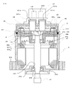
- FIG. 2 is a sectional view of the electric power steering apparatus according to Embodiment 1 of the present invention
- FIG. 3 is a plan view of a control unit in the electric power steering apparatus according to Embodiment 1 of the present invention.
- the electric motor 2 is arranged at the lower part in the figure
- the control unit 1 including the first control unit 1a and the second control unit 1b is arranged at the upper part in the figure.
- the electric motor 2 and the control unit 1 are arranged coaxially on the axis of the output shaft 21 of the electric motor 2 and integrated.
- a metal electric motor case 25 formed in a cylindrical shape is used for mechanically connecting an attachment flange portion 25a for attaching the electric power steering device to a mechanism portion or the like of a vehicle and a speed reducer (not shown).
- An end wall portion 250 integrally formed with the connecting portion 25b is provided.
- the electric motor case 25 is preferably formed of, for example, aluminum in consideration of heat dissipation and the shape of the outer shape.
- the stator 22 and the rotor 23 of the electric motor 2 are housed inside an electric motor case 25.
- An output side end portion of the output shaft 21 of the electric motor 2 in the axial direction is freely rotatable by a first bearing 29b mounted in an end wall portion through-hole 251 provided in the radial center portion of the end wall portion 250. And protrudes through the end wall through hole 251 to the speed reducer side.
- the rotor 23 is fixed to the output shaft 21, and a plurality of pairs of field magnetic poles composed of permanent magnets are arranged in the circumferential direction.
- the circumferential surface of the rotor 23 is disposed to face the inner circumferential surface of the stator 22 with a gap.
- the stator 22 is wound with a first armature winding 201 and a second armature winding 202.
- Three first winding terminals 26a of each phase winding of the first armature winding 201 are electrically connected to a connection conductor of a connection ring 27 arranged in the immediate vicinity of the armature winding.
- the ring 27 extends in the axial direction of the electric motor 2 from the axial end surface of the ring 27 toward the control unit 1.
- each phase winding of the second armature winding 202 are electrically connected to the connection conductor of the connection ring 27, and are connected to the first via the output shaft 21. Extending from the axial end face of the connection ring 27 in the direction of the control unit 1 in the axial direction of the electric motor 2 at a position facing the winding terminal 26a.
- the frame 28 is attached in a state inscribed in the end of the electric motor case 25 on the side opposite to the speed reducer in the axial direction.
- the frame 28 is also made of metal, and a second bearing 29a is mounted in a frame through hole 281 formed in the central portion in the radial direction.
- the opposite end of the output shaft 21 of the electric motor 2 is rotatably supported by the second bearing 29a.
- the rotation sensor rotor 16c described above is fixed to the end of the output shaft 21 of the electric motor 2 on the opposite side to the output side.
- the frame 28 has a first winding terminal through hole 28a for passing through the first winding terminal 26a and a second winding terminal penetration for passing through the second winding terminal 26b. And a through hole 28b.
- the first winding terminal 26 a described above passes through the first winding terminal through hole 28 a and extends in the direction of the control board 4 in the axial direction of the electric motor 2.
- the second winding terminal 26 b extends through the second winding terminal through hole through hole 28 b and extends in the axial direction of the electric motor 2 in the direction of the control board 4.
- the frame 28 has a plurality of functions such as a function as a partition wall that separates the electric motor 2 and the control unit 1 and a function of holding the second bearing 29a. Furthermore, a heat sink function for heat radiation of the control unit 1 is also provided. Thus, since the frame 28 has many functions, the number of parts can be reduced.
- the electric motor 2 includes the output shaft 21, the rotor 23, the stator 22, the first armature winding 201, the second armature winding 202, the connection ring 27, the frame 28, and the first bearing. 29 b and the second bearing 29 a are built in the electric motor case 25. Therefore, the electric motor 2 can be assembled separately from the control unit 1. The electric motor 2 and the control unit 1 are integrated with each other after being individually assembled.
- the control unit 1 is composed of a first control unit 1a and a second control unit 1b shown in FIG. 1, and is covered by a housing 40 fixed to an end portion in the axial direction of a metal electric motor case 25. Yes.
- the interior of the housing 40 is partitioned into a first chamber 41 and a second chamber 43 by an inner housing 46 described later.
- the first chamber 41 incorporates a control board 4 on which a control circuit unit including a first control circuit unit 4a and a second control circuit unit 4b is mounted.
- the CPU 10 constituted by the first CPU 10 a and the second CPU 10 b is mounted on the surface of the control board 4 on the counter-electric motor 2 side.
- both 1st CPU10a of FIG. 1 and 2nd CPU10b are built in one package.
- Each phase switching element such as U-phase upper arm switching element 31U and U-phase lower arm switching element 32U of first inverter circuit 3a, and U-phase upper arm switching element 311U, U of each phase of second inverter circuit 3b
- the switching elements of each phase such as the lower arm switching element 321U are mounted on the surface of the control board 4 on the electric motor 2 side (only the reference numeral 311U is shown in FIG. 2).
- the first motor switching elements 34U, 34V, 34W for each phase of the first inverter circuit 3a and the second motor switching elements 341U, 341V, 341W for each phase of the second inverter circuit 3b are controlled. It is mounted on the surface of the substrate 4 on the electric motor 2 side (in FIG. 2, only the symbol 34U is displayed).
- the first winding terminal 26a described above passes through the first winding terminal through hole through hole 28a, passes through the peripheral edge of the control board 4, and further passes through the through hole of the housing 40, so that the housing 40 It extends to the outside. It extends in the axial direction of the electric motor 2.
- the second winding terminal 26 b passes through the peripheral edge of the control board 4 through the second winding terminal through hole through hole 28 b, and further passes through the through hole of the housing 40 to the outside of the housing 40. It extends to.
- the inner housing 46 described above is disposed inside the housing 40 and is fixed to the axial end of the frame 28.
- the inner housing 46 is made of, for example, an insulating resin and has the filter unit 6 shown in FIG.
- the inner housing 46 includes switching elements of respective phases such as the U-phase upper arm switching element 31U and the U-phase lower arm switching element 32U of the first inverter circuit 3a, and the first motor switching elements 34U, 34V, 34W.
- the above-described filter unit 6 is incorporated in the second chamber 43 of the housing 40.
- the housing 40 is formed such that a portion corresponding to the second chamber 43 protrudes toward the counter electric motor 2 as shown in the drawing.
- a power connector 42 having a + B terminal and a GND terminal is disposed in a portion corresponding to the second chamber 43 of the housing 40.
- the power connector 42 and the housing 40 are made of an integrated resin.
- the power switching elements such as the switching elements 311U and 34U mounted on the surface of the control board 4 on the electric motor 2 side generate heat by switching control. Therefore, these power switching elements are arranged such that their surfaces abut against the surface of the frame 28 and are configured to be able to transfer heat to the frame 28. That is, the frame 28 also functions as a heat sink.
- first winding terminal 26 a and the second winding terminal 26 b pass through the peripheral portion of the control board 4, penetrate the housing 40, and extend to the outside of the housing 40.
- first conductor 451a and the second conductor 451b from the switching elements such as the switching elements 311U and 34U of the control board 4 penetrate the housing 40 and extend to the outside of the housing 40, respectively.
- the ends of the terminals 26a and 26b are electrically connected, for example, by welding. These connecting portions are covered by covers 47a and 47b.
- connection part of the 1st winding terminal 26a, the 2nd winding terminal 26b, the 1st conductor 451a, and the 2nd conductor 451b is arrange
- Workability for connection is improved. For example, it is not necessary to consider the spatter due to welding, the arrangement of welding tools, and the like, and the workability is remarkably improved as compared with the case where it is performed inside the control unit 1.
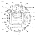
- FIG. 3 is an explanatory diagram of a control unit in the electric power steering apparatus according to Embodiment 1 of the present invention.
- the arrangement of the conductors from the + B terminal and the GND terminal in the power supply connector 42 to the control board 4 through the filter unit 6 is directly connected as shown in the circuit of FIG.
- the conductor also needs to have a width and thickness suitable for the current, which hinders miniaturization. Therefore, the power connector 42 is disposed at a substantially central portion of the housing 40 as shown in FIG.
- the power connector 42 has a + B terminal and a GND terminal. These terminals extend through the housing 40 and are connected to the bus bars 45a and 45b.
- bus bars 45a and 45b are connected to the components of the filter unit 6 in FIG.
- the common mode coil 6a and then the normal mode coil 6b are disposed below the power connector 42 and connected to the bus bars 45a and 45b.
- the power connector 42 and the parts of the large-sized filter unit 6 are three-dimensionally arranged to reduce the mounting area, thereby reducing the size.
- a first signal connector 48a and a second signal connector 48b for the sensors 8 are separately arranged on the left and right sides.
- the first signal connector 48a is connected to the first input circuit 12a of the first control circuit unit 4a
- the second signal connector 48b is the second input circuit 12b of the second control circuit unit 4b.
- the first winding terminal 26a and the second winding terminal 26b are disposed substantially symmetrically around the periphery of the housing 40 with the filter portion 6 interposed therebetween, and are connected to the first conductor 451a and the second conductor 451b. Each is connected.
- the connection position between the first winding terminal 26 a and the first conductor 451 a and the connection position between the second winding terminal 26 b and the second conductor 451 b are arranged substantially symmetrically with respect to the center of the housing 40. ing.
- the first signal connector 48a and the second signal connector 48b are arranged around the housing 40, and further, the first winding terminal 26a, the second winding terminal 26b, Since the respective connection positions of the conductor 451a and the second winding terminal 451b are arranged around the housing 40, the conductive wires extending from these are arranged at the peripheral edge of the control board 4 or at the periphery. Thus, the effective area of the control board 4 is not reduced.
- the electric power steering apparatus is integrated by mounting the control unit 1 at the axial end opposite to the output shaft 21 of the electric motor 2. Since the power supply connector is arranged at the approximate center of the housing and the filter unit 6 is arranged below it, the winding terminal and the signal connector are arranged at the peripheral part of the housing 40. Each component can be arranged within the diameter, and the size can be reduced. Also, with this arrangement, it is possible to shorten the wiring from the power supply terminal via the filter unit 6 as much as possible. Furthermore, since the connection position of each winding terminal 26a, 26b and the switching element is on the peripheral side of the housing, workability can be improved.
- FIG. 4 is a sectional view of an electric power steering apparatus according to Embodiment 2 of the present invention
- FIG. 5 is an explanatory view of a control unit in the electric power steering apparatus according to Embodiment 2 of the present invention.
- the same or corresponding parts as those in FIGS. 1, 2, and 3 are denoted by the same reference numerals.
- the differences from the first embodiment are the connection structure of the first winding terminal 26a and the second winding terminal 26b of the electric motor 2, the first capacitor 30a and the second capacitor in the control unit 1. 30b, the third capacitor 301a, and the fourth capacitor 301b.
- the control unit 1 is arranged coaxially with the output shaft 21 of the electric motor 2 and on the opposite side of the electric motor 2 in the axial direction.
- Three first winding terminals 26a of each phase winding of the first armature winding 201 are electrically connected to a connection conductor of a connection ring 27 arranged in the immediate vicinity of the armature winding.
- the ring 27 extends in the axial direction of the electric motor 2 from the axial end surface of the ring 27 toward the control unit 1, but the tip end of the ring 27 remains inside the housing 40 without penetrating the housing 40.
- the three second winding terminals 26 b of each phase winding of the second armature winding 202 are electrically connected to the connection conductor of the connection ring 27, and are connected to the first via the output shaft 21.
- the electric motor 2 extends in the axial direction from the axial end face of the connection ring 27 to the control unit 1 at a position facing the winding terminal 26 a, the tip of the electric motor 2 does not penetrate the housing 40. Stays inside.
- a terminal 50 is installed on the control board 4.
- the terminal 50 includes a conductive plate 50a and an insulating resin portion 50b.
- One end of the conductive plate 50a is connected to the switching elements 31U, 31V, 31W of each arm of the first inverter circuit 3a and the switching element 311U of each arm of the second inverter circuit 3b via the conductive pattern of the control board 4.
- 311V, 311W (only reference numeral 311U is shown in FIG. 4)
- the second motor switching elements 341U, 341V, and 341W of each phase 3b are connected.
- the other end of the conductive plate 50a is covered with an insulating resin portion 50b.
- the insulating resin portion 50b is provided with a window portion, and the conductive plate 50a is at least two in a fork shape in the window portion.
- the books are arranged separately.
- FIG. 5 shows that two fork-shaped conductive plates 50a are arranged.
- the first winding terminal 26a and the second winding terminal 26b are inserted between the portions of the conductive plate 50a that are separated in a fork shape, fitted into the conductive plate 50a, and electrically connected by press fitting. It is connected to the.
- Part of the insulating resin portion 50b is in contact with the inner housing 46, and the positioning of the terminal 50 and the insertion of the first winding terminal 26a and the second winding terminal 26b into the conductive plate 50a. When the pressure is received.
- the control board 4 includes a first capacitor 30a, a second capacitor 30b, and a switching circuit in the second inverter circuit 3b in order to suppress noise of the switching element in the first inverter circuit 3a shown in FIG.
- a third capacitor 301a and a fourth capacitor 301b are connected to suppress element noise.
- These capacitors 30a, 30b, 301a, and 301b are mounted on the control board 4, but these capacitors 30a, 30b, 301a, and 301b are relatively large components, and therefore, as shown in FIG. It extends through the through hole provided in the housing 46 so as to exceed the end face of the housing 40.
- the housing 40 includes cylindrical convex portions 41a, 411a, 41b, and 411b at positions corresponding to the capacitors 30a, 30b, 301a, and 301b.
- the convex portions 41a, 411a, 41b, and 411b , Part of capacitors 30a, 30b, 301a, 301b are housed.
- the convex portions 41a, 411a, 41b, and 411b for the capacitors can be disposed in a three-dimensional manner without overlapping with these.
- the capacitors 30a, 30b, 301a, 301b are disposed at substantially target positions as shown in FIG. This is because the first inverter circuit 3a and the second inverter circuit 3b have the same circuit configuration, and both have the same components, and as a result, the capacitors 30a, 30b, 301a, and 301b are also symmetric. Can be arranged. Due to this symmetrical arrangement, an electrical difference between the first inverter circuit 3a and the second inverter circuit 3b, for example, a difference in network impedance, is suppressed as much as possible.
- the connection between the winding terminal and the control circuit unit is performed in the control unit 1, so that the assembly can be simplified. Moreover, a tall capacitor can be accommodated in the convex part provided in the housing 40. As a result, all parts are arranged within the diameter of the electric motor 2 without increasing the diameter of the electric motor 2. Can be reduced and the size can be reduced.
- the present invention is not limited to the electric power steering drive device according to the first and second embodiments described above, and the configurations of the first and second embodiments may be combined as appropriate without departing from the spirit of the present invention. It is possible to add a part of the configuration or to omit a part of the configuration.
- SYMBOLS 1 Control unit 1a 1st control unit, 1b 1st control unit, 2 Electric motor, 3a 1st inverter circuit, 3b 2nd inverter circuit, 4 Control board, 4a 1st control circuit part, 4b 1st 2 control circuit section, 5a first power relay, 5b second power relay, 6 filter section, 8 sensors, 10a first CPU, 10b second CPU, 11a first drive circuit, 11b 2nd drive circuit, 12a 1st input circuit, 12b 2nd input circuit, 13a 1st power supply circuit, 13b 2nd power supply circuit, 16a 1st rotation sensor, 16b 2nd rotation sensor, 30a 2nd 1 capacitor, 30b second capacitor, 31U, 32U, 311U, 321U, 34U, 34V, 34W, 341U, 341V, 341W switching element, 40 housing 42 Power connector 46 inner housing 50 terminal.
Priority Applications (5)
| Application Number | Priority Date | Filing Date | Title |
|---|---|---|---|
| JP2018510166A JP6580251B2 (ja) | 2016-04-06 | 2016-04-06 | 電動パワーステアリング装置 |
| EP16897884.9A EP3441285B1 (de) | 2016-04-06 | 2016-04-06 | Elektrische servolenkvorrichtung |
| PCT/JP2016/061211 WO2017175325A1 (ja) | 2016-04-06 | 2016-04-06 | 電動パワーステアリング装置 |
| CN201680084252.4A CN109070933B (zh) | 2016-04-06 | 2016-04-06 | 电动助力转向装置 |
| US15/780,474 US10906577B2 (en) | 2016-04-06 | 2016-04-06 | Electric power steering apparatus |
Applications Claiming Priority (1)
| Application Number | Priority Date | Filing Date | Title |
|---|---|---|---|
| PCT/JP2016/061211 WO2017175325A1 (ja) | 2016-04-06 | 2016-04-06 | 電動パワーステアリング装置 |
Publications (1)
| Publication Number | Publication Date |
|---|---|
| WO2017175325A1 true WO2017175325A1 (ja) | 2017-10-12 |
Family
ID=60001015
Family Applications (1)
| Application Number | Title | Priority Date | Filing Date |
|---|---|---|---|
| PCT/JP2016/061211 WO2017175325A1 (ja) | 2016-04-06 | 2016-04-06 | 電動パワーステアリング装置 |
Country Status (5)
| Country | Link |
|---|---|
| US (1) | US10906577B2 (de) |
| EP (1) | EP3441285B1 (de) |
| JP (1) | JP6580251B2 (de) |
| CN (1) | CN109070933B (de) |
| WO (1) | WO2017175325A1 (de) |
Cited By (14)
| Publication number | Priority date | Publication date | Assignee | Title |
|---|---|---|---|---|
| CN109367376A (zh) * | 2018-11-26 | 2019-02-22 | 中国科学院电工研究所 | 一种电机和控制器的集成系统 |
| CN109510407A (zh) * | 2018-11-26 | 2019-03-22 | 中国科学院电工研究所 | 一种电机和控制器的集成系统 |
| WO2019073594A1 (ja) * | 2017-10-13 | 2019-04-18 | 三菱電機株式会社 | 電動パワーステアリング装置 |
| WO2019077647A1 (ja) * | 2017-10-16 | 2019-04-25 | 三菱電機株式会社 | 電動パワーステアリング装置 |
| WO2019181105A1 (ja) * | 2018-03-22 | 2019-09-26 | クノールブレムゼステアリングシステムジャパン株式会社 | 車両搭載機器 |
| WO2019198655A1 (ja) * | 2018-04-10 | 2019-10-17 | 株式会社デンソー | 駆動装置 |
| WO2019198658A1 (ja) * | 2018-04-10 | 2019-10-17 | 株式会社デンソー | 駆動装置および駆動ユニット |
| WO2020110261A1 (ja) * | 2018-11-29 | 2020-06-04 | 三菱電機株式会社 | 電動駆動装置 |
| JP2021520181A (ja) * | 2018-03-30 | 2021-08-12 | ハルデックス ヴィー(シャンハイ)エレクトロメカニカル ブレーキ システム シーオー.,エルティーディー. | 電気機械式ブレーキ及びその電動アクチュエータ |
| WO2021161947A1 (ja) * | 2020-02-14 | 2021-08-19 | 株式会社デンソー | 駆動装置 |
| WO2021192202A1 (ja) * | 2020-03-27 | 2021-09-30 | 三菱電機株式会社 | 回転電機装置および電動パワーステアリング装置 |
| JP7021383B1 (ja) | 2021-04-23 | 2022-02-16 | ナブテスコ株式会社 | 操舵装置 |
| WO2022097325A1 (ja) * | 2020-11-06 | 2022-05-12 | 日立Astemo株式会社 | 電動機駆動制御装置 |
| WO2023209787A1 (ja) * | 2022-04-26 | 2023-11-02 | 三菱電機株式会社 | 電動パワーステアリング装置 |
Families Citing this family (7)
| Publication number | Priority date | Publication date | Assignee | Title |
|---|---|---|---|---|
| JP6539997B2 (ja) * | 2014-11-25 | 2019-07-10 | 日本電産株式会社 | モータ |
| JP6691346B2 (ja) * | 2016-04-15 | 2020-04-28 | ミネベアミツミ株式会社 | モータ |
| WO2018211726A1 (ja) * | 2017-05-17 | 2018-11-22 | 日本電産株式会社 | モータ及び電動パワーステアリング装置 |
| JP6606780B1 (ja) * | 2018-10-09 | 2019-11-20 | 三菱電機株式会社 | 車両用電動制動装置およびその制御方法 |
| CN114945503B (zh) * | 2020-01-16 | 2024-04-19 | 海拉有限双合股份公司 | 用于车辆的电动设备 |
| CN115298935A (zh) * | 2020-03-27 | 2022-11-04 | 三菱电机株式会社 | 旋转电机装置及电动助力转向装置 |
| WO2023017828A1 (en) * | 2021-08-13 | 2023-02-16 | Valeo Japan Co., Ltd. | An electric machine |
Citations (6)
| Publication number | Priority date | Publication date | Assignee | Title |
|---|---|---|---|---|
| JP2013207963A (ja) * | 2012-03-29 | 2013-10-07 | Denso Corp | 駆動装置およびその製造方法 |
| JP2015089215A (ja) * | 2013-10-30 | 2015-05-07 | 株式会社デンソー | 回転電機 |
| JP2015122824A (ja) * | 2013-12-20 | 2015-07-02 | 日本精工株式会社 | 電子制御ユニット、電動パワーステアリング装置及び車両 |
| JP2015154673A (ja) * | 2014-02-18 | 2015-08-24 | 株式会社デンソー | 回転電機 |
| JP2016034201A (ja) * | 2014-07-31 | 2016-03-10 | 株式会社デンソー | 駆動装置 |
| JP2016036244A (ja) * | 2014-07-31 | 2016-03-17 | 株式会社デンソー | 駆動装置、および、これを用いた電動パワーステアリング装置 |
Family Cites Families (9)
| Publication number | Priority date | Publication date | Assignee | Title |
|---|---|---|---|---|
| JP3911671B2 (ja) * | 2002-05-30 | 2007-05-09 | ミネベア株式会社 | モータ |
| JP5003005B2 (ja) * | 2006-04-11 | 2012-08-15 | 日本精工株式会社 | 電動パワーステアリング装置 |
| US9586615B2 (en) * | 2012-01-25 | 2017-03-07 | Mitsubishi Electric Corporation | Electric power steering apparatus |
| EP2824807B1 (de) * | 2012-03-06 | 2017-08-23 | Mitsubishi Electric Corporation | Elektrische servolenk-antriebsvorrichtung |
| JP5827157B2 (ja) | 2012-03-21 | 2015-12-02 | 日立オートモティブシステムズ株式会社 | 電動アクチュエータの端子接続構造 |
| JP5853820B2 (ja) | 2012-03-29 | 2016-02-09 | 株式会社デンソー | 駆動装置 |
| EP2824014B1 (de) * | 2013-07-08 | 2015-10-21 | Fagor, S. Coop. | Elektrische antriebsvorrichtung |
| US10211709B2 (en) | 2014-03-26 | 2019-02-19 | Mitsubishi Electric Corporation | Electric power steering device |
| JP6172217B2 (ja) | 2014-07-31 | 2017-08-02 | 株式会社デンソー | 駆動装置、および、これを用いた電動パワーステアリング装置 |
-
2016
- 2016-04-06 EP EP16897884.9A patent/EP3441285B1/de active Active
- 2016-04-06 CN CN201680084252.4A patent/CN109070933B/zh active Active
- 2016-04-06 WO PCT/JP2016/061211 patent/WO2017175325A1/ja unknown
- 2016-04-06 JP JP2018510166A patent/JP6580251B2/ja active Active
- 2016-04-06 US US15/780,474 patent/US10906577B2/en active Active
Patent Citations (6)
| Publication number | Priority date | Publication date | Assignee | Title |
|---|---|---|---|---|
| JP2013207963A (ja) * | 2012-03-29 | 2013-10-07 | Denso Corp | 駆動装置およびその製造方法 |
| JP2015089215A (ja) * | 2013-10-30 | 2015-05-07 | 株式会社デンソー | 回転電機 |
| JP2015122824A (ja) * | 2013-12-20 | 2015-07-02 | 日本精工株式会社 | 電子制御ユニット、電動パワーステアリング装置及び車両 |
| JP2015154673A (ja) * | 2014-02-18 | 2015-08-24 | 株式会社デンソー | 回転電機 |
| JP2016034201A (ja) * | 2014-07-31 | 2016-03-10 | 株式会社デンソー | 駆動装置 |
| JP2016036244A (ja) * | 2014-07-31 | 2016-03-17 | 株式会社デンソー | 駆動装置、および、これを用いた電動パワーステアリング装置 |
Cited By (36)
| Publication number | Priority date | Publication date | Assignee | Title |
|---|---|---|---|---|
| US11565741B2 (en) | 2017-10-13 | 2023-01-31 | Mitsubishi Electric Corporation | Electric power steering device |
| CN111183570B (zh) * | 2017-10-13 | 2022-07-08 | 三菱电机株式会社 | 电动助力转向装置 |
| WO2019073594A1 (ja) * | 2017-10-13 | 2019-04-18 | 三菱電機株式会社 | 電動パワーステアリング装置 |
| CN111183570A (zh) * | 2017-10-13 | 2020-05-19 | 三菱电机株式会社 | 电动助力转向装置 |
| JPWO2019073594A1 (ja) * | 2017-10-13 | 2020-04-02 | 三菱電機株式会社 | 電動パワーステアリング装置 |
| US11440581B2 (en) | 2017-10-16 | 2022-09-13 | Mitsubishi Electric Corporation | Electric power steering device |
| JPWO2019077647A1 (ja) * | 2017-10-16 | 2020-04-02 | 三菱電機株式会社 | 電動パワーステアリング装置 |
| WO2019077647A1 (ja) * | 2017-10-16 | 2019-04-25 | 三菱電機株式会社 | 電動パワーステアリング装置 |
| JP2019166880A (ja) * | 2018-03-22 | 2019-10-03 | クノールブレムゼステアリングシステムジャパン株式会社 | 車両搭載機器 |
| CN111902330B (zh) * | 2018-03-22 | 2022-09-06 | 克诺尔转向系统日本有限公司 | 车辆搭载设备 |
| WO2019181105A1 (ja) * | 2018-03-22 | 2019-09-26 | クノールブレムゼステアリングシステムジャパン株式会社 | 車両搭載機器 |
| US11945522B2 (en) | 2018-03-22 | 2024-04-02 | Knorr-Bremse Commercial Vehicle Systems Japan Ltd. | Vehicle-mounted apparatus |
| CN111902330A (zh) * | 2018-03-22 | 2020-11-06 | 克诺尔转向系统日本有限公司 | 车辆搭载设备 |
| JP7067983B2 (ja) | 2018-03-22 | 2022-05-16 | クノールブレムゼステアリングシステムジャパン株式会社 | 車両搭載機器 |
| JP7377252B2 (ja) | 2018-03-30 | 2023-11-09 | ハルデックス・ヴィーアイイー・(シャンハイ)・エレクトロメカニカル・ブレイク・システム・カンパニー・リミテッド | 電気機械式ブレーキ及びその電動アクチュエータ |
| JP2021520181A (ja) * | 2018-03-30 | 2021-08-12 | ハルデックス ヴィー(シャンハイ)エレクトロメカニカル ブレーキ システム シーオー.,エルティーディー. | 電気機械式ブレーキ及びその電動アクチュエータ |
| JP2019187080A (ja) * | 2018-04-10 | 2019-10-24 | 株式会社デンソー | 駆動装置および駆動ユニット |
| JP2019187078A (ja) * | 2018-04-10 | 2019-10-24 | 株式会社デンソー | 駆動装置 |
| WO2019198655A1 (ja) * | 2018-04-10 | 2019-10-17 | 株式会社デンソー | 駆動装置 |
| WO2019198658A1 (ja) * | 2018-04-10 | 2019-10-17 | 株式会社デンソー | 駆動装置および駆動ユニット |
| CN109510407A (zh) * | 2018-11-26 | 2019-03-22 | 中国科学院电工研究所 | 一种电机和控制器的集成系统 |
| CN109367376B (zh) * | 2018-11-26 | 2024-03-19 | 中国科学院电工研究所 | 一种电机和控制器的集成系统 |
| CN109510407B (zh) * | 2018-11-26 | 2024-01-26 | 中国科学院电工研究所 | 一种电机和控制器的集成系统 |
| CN109367376A (zh) * | 2018-11-26 | 2019-02-22 | 中国科学院电工研究所 | 一种电机和控制器的集成系统 |
| EP3890169A4 (de) * | 2018-11-29 | 2021-12-01 | Mitsubishi Electric Corporation | Elektrische antriebsvorrichtung |
| JPWO2020110261A1 (ja) * | 2018-11-29 | 2021-04-30 | 三菱電機株式会社 | 電動駆動装置 |
| WO2020110261A1 (ja) * | 2018-11-29 | 2020-06-04 | 三菱電機株式会社 | 電動駆動装置 |
| WO2021161947A1 (ja) * | 2020-02-14 | 2021-08-19 | 株式会社デンソー | 駆動装置 |
| JP7321361B2 (ja) | 2020-03-27 | 2023-08-04 | 三菱電機株式会社 | 回転電機装置および電動パワーステアリング装置 |
| WO2021192202A1 (ja) * | 2020-03-27 | 2021-09-30 | 三菱電機株式会社 | 回転電機装置および電動パワーステアリング装置 |
| WO2022097325A1 (ja) * | 2020-11-06 | 2022-05-12 | 日立Astemo株式会社 | 電動機駆動制御装置 |
| JP7461500B2 (ja) | 2020-11-06 | 2024-04-03 | 日立Astemo株式会社 | 電動機駆動制御装置 |
| US11661104B2 (en) | 2021-04-23 | 2023-05-30 | Nabtesco Corporation | Steering device |
| JP2022167573A (ja) * | 2021-04-23 | 2022-11-04 | ナブテスコ株式会社 | 操舵装置 |
| JP7021383B1 (ja) | 2021-04-23 | 2022-02-16 | ナブテスコ株式会社 | 操舵装置 |
| WO2023209787A1 (ja) * | 2022-04-26 | 2023-11-02 | 三菱電機株式会社 | 電動パワーステアリング装置 |
Also Published As
| Publication number | Publication date |
|---|---|
| EP3441285A1 (de) | 2019-02-13 |
| JPWO2017175325A1 (ja) | 2018-08-09 |
| JP6580251B2 (ja) | 2019-09-25 |
| CN109070933B (zh) | 2021-03-19 |
| EP3441285B1 (de) | 2020-12-09 |
| CN109070933A (zh) | 2018-12-21 |
| EP3441285A4 (de) | 2019-03-20 |
| US20190016371A1 (en) | 2019-01-17 |
| US10906577B2 (en) | 2021-02-02 |
Similar Documents
| Publication | Publication Date | Title |
|---|---|---|
| JP6580251B2 (ja) | 電動パワーステアリング装置 | |
| JP5951067B1 (ja) | 電動パワーステアリング装置 | |
| JP6509359B2 (ja) | 一体型電動パワーステアリング装置、及びその製造方法 | |
| JP7094371B2 (ja) | 電動パワーステアリング装置 | |
| JP5039171B2 (ja) | 電動式駆動装置およびその電動式駆動装置を搭載した電動式パワーステアリング装置 | |
| US8924081B2 (en) | Electric power steering apparatus and control device integrated-type electric motor | |
| JP5619279B2 (ja) | 電動パワーステアリング装置 | |
| JP2017189033A (ja) | 駆動装置、および、これを用いた電動パワーステアリング装置 | |
| US11565741B2 (en) | Electric power steering device | |
| JP6608555B1 (ja) | 駆動装置、および電動パワーステアリング装置 | |
| WO2016075821A1 (ja) | 制御ユニットおよびこれを用いた電動パワーステアリング装置 | |
| US20200140004A1 (en) | Driving device and electric power steering apparatus using the same | |
| JP2019068542A (ja) | 回路基板、モータ駆動装置および電動パワーステアリング装置 | |
| WO2018070004A1 (ja) | 電動パワーステアリング装置 | |
| JP2019187079A (ja) | 駆動装置 | |
| EP3264590B1 (de) | Elektrische antriebsvorrichtung und steuerungsverfahren dafür | |
| JP2020195236A (ja) | 電動ステアリング装置 | |
| JP2020145856A (ja) | モータ制御ユニットおよびモータ | |
| JP2005178613A (ja) | ステアバイワイヤシステム | |
| JP2023116049A (ja) | 駆動装置 | |
| JP2023116027A (ja) | 駆動装置 | |
| JP2023116040A (ja) | 駆動装置 | |
| JP2021007286A (ja) | 駆動装置 |
Legal Events
| Date | Code | Title | Description |
|---|---|---|---|
| ENP | Entry into the national phase |
Ref document number: 2018510166 Country of ref document: JP Kind code of ref document: A |
|
| NENP | Non-entry into the national phase |
Ref country code: DE |
|
| 121 | Ep: the epo has been informed by wipo that ep was designated in this application |
Ref document number: 16897884 Country of ref document: EP Kind code of ref document: A1 |