WO2019073594A1 - 電動パワーステアリング装置 - Google Patents
電動パワーステアリング装置 Download PDFInfo
- Publication number
- WO2019073594A1 WO2019073594A1 PCT/JP2017/037182 JP2017037182W WO2019073594A1 WO 2019073594 A1 WO2019073594 A1 WO 2019073594A1 JP 2017037182 W JP2017037182 W JP 2017037182W WO 2019073594 A1 WO2019073594 A1 WO 2019073594A1
- Authority
- WO
- WIPO (PCT)
- Prior art keywords
- power module
- output shaft
- motor
- control board
- control
- Prior art date
Links
Images


Classifications
-
- B—PERFORMING OPERATIONS; TRANSPORTING
- B62—LAND VEHICLES FOR TRAVELLING OTHERWISE THAN ON RAILS
- B62D—MOTOR VEHICLES; TRAILERS
- B62D5/00—Power-assisted or power-driven steering
- B62D5/04—Power-assisted or power-driven steering electrical, e.g. using an electric servo-motor connected to, or forming part of, the steering gear
- B62D5/0457—Power-assisted or power-driven steering electrical, e.g. using an electric servo-motor connected to, or forming part of, the steering gear characterised by control features of the drive means as such
- B62D5/046—Controlling the motor
-
- H—ELECTRICITY
- H02—GENERATION; CONVERSION OR DISTRIBUTION OF ELECTRIC POWER
- H02K—DYNAMO-ELECTRIC MACHINES
- H02K11/00—Structural association of dynamo-electric machines with electric components or with devices for shielding, monitoring or protection
- H02K11/30—Structural association with control circuits or drive circuits
- H02K11/33—Drive circuits, e.g. power electronics
-
- B—PERFORMING OPERATIONS; TRANSPORTING
- B62—LAND VEHICLES FOR TRAVELLING OTHERWISE THAN ON RAILS
- B62D—MOTOR VEHICLES; TRAILERS
- B62D5/00—Power-assisted or power-driven steering
- B62D5/04—Power-assisted or power-driven steering electrical, e.g. using an electric servo-motor connected to, or forming part of, the steering gear
- B62D5/0403—Power-assisted or power-driven steering electrical, e.g. using an electric servo-motor connected to, or forming part of, the steering gear characterised by constructional features, e.g. common housing for motor and gear box
- B62D5/0406—Power-assisted or power-driven steering electrical, e.g. using an electric servo-motor connected to, or forming part of, the steering gear characterised by constructional features, e.g. common housing for motor and gear box including housing for electronic control unit
-
- H—ELECTRICITY
- H02—GENERATION; CONVERSION OR DISTRIBUTION OF ELECTRIC POWER
- H02K—DYNAMO-ELECTRIC MACHINES
- H02K9/00—Arrangements for cooling or ventilating
- H02K9/22—Arrangements for cooling or ventilating by solid heat conducting material embedded in, or arranged in contact with, the stator or rotor, e.g. heat bridges
- H02K9/227—Heat sinks
-
- G—PHYSICS
- G01—MEASURING; TESTING
- G01L—MEASURING FORCE, STRESS, TORQUE, WORK, MECHANICAL POWER, MECHANICAL EFFICIENCY, OR FLUID PRESSURE
- G01L3/00—Measuring torque, work, mechanical power, or mechanical efficiency, in general
- G01L3/02—Rotary-transmission dynamometers
- G01L3/04—Rotary-transmission dynamometers wherein the torque-transmitting element comprises a torsionally-flexible shaft
Definitions
- the present invention relates to an electric power steering apparatus in which a motor and a control unit are integrated, and more particularly to the structure of a control unit provided with two sets of motor drive circuits.
- the conventional drive device is configured by integrating a motor and a control unit coaxially arranged in the axial direction of the output shaft of the motor.
- a stator, a rotor, and the like are built in a motor case, and a control unit disposed in the vicinity of the motor has a structure in which main components are assembled in an axial direction.
- a conventional device has been developed which has two sets of motor windings and two sets of so-called inverter circuits and control boards for independently driving them (see, for example, Patent Document 1).
- the conventional device disclosed in Patent Document 1 has a structure in which a motor and a control unit disposed at the end of the motor opposite to the output side of the output shaft of the motor are integrated.
- the mounting on the vehicle often makes it difficult to mount the vehicle when the control unit expands in the radial direction of the motor.
- the length in the output shaft direction of the motor of the conventional device is often acceptable even if it is relatively long. From these facts, in consideration of mounting the conventional device on a vehicle, the radial area of the control unit needs to be equal to or smaller than that of the motor.
- the power module and the heat sink which comprise a control unit were arrange
- the control board was disposed perpendicularly to the axial direction of the output shaft, that is, laterally placed. Then, the control board is at the boundary separating the motor and the control unit. The side opposite to the output side of the output shaft of the motor is the opposite side.
- the conventional device has two sets of power modules and two sets of control circuits for independently driving each of the power modules, and in order to incorporate them in the outer shell of the control unit, the two sets of power modules And two sets of control boards are arranged vertically on the arrangement surface of the heat sink.
- the control substrate and the power module are disposed so as to overlap in the radial direction on each of a pair of opposing arrangement surfaces formed on the heat sink. Therefore, there has been a problem that it leads to an increase in the size of the product, particularly in the radial direction. On the other hand, by increasing the width of the control substrate, it is possible to suppress the increase in the radial direction.
- the present invention has been made to solve the above-described problems, and provides an electric power steering apparatus that can be miniaturized and has two sets of circuit configurations in consideration of redundancy.
- An electric power steering apparatus comprises a motor, and a control unit disposed in the axial direction of the output shaft of the motor and integrated with the motor.
- the motor includes a first motor winding and a second motor winding
- the control unit includes a first power module having a plurality of first switching elements for supplying current to the first motor winding.
- a second control module for outputting control signals to the plurality of first switching elements, a second power module having a plurality of second switching elements for supplying a current to the second motor winding, and the plurality of second switching elements
- a second control substrate for outputting a control signal to the element, a heat sink for dissipating heat generated by the control unit, and a housing forming an outer shell of the control unit.
- the heat sink includes a column portion extending in the axial direction of the output shaft on an extension of the axial center of the output shaft in the housing, and the column portion includes a plurality of planes parallel to the axial direction of the output shaft
- the first power module wherein the first control substrate and the second control substrate are disposed one by one along each of a pair of opposing placement portions among the plurality of placement portions; And the second power module are disposed one by one along each of another pair of opposing placement portions in the plurality of placement portions.
- the pillar portion, the first control board, and the second control board are vertically disposed, and after the effective area in the housing is expanded, the plurality of arrangements of the first control board and the second control board are performed.
- the first power module and the second power module are disposed one by one along each of a pair of opposing placement parts in the part, and each of the other pair of opposing placement parts in the plurality of placement parts Are arranged one by one along the.
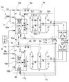
- FIG. 1 is a circuit diagram of an electric power steering apparatus according to Embodiment 1 of the present invention.
- BRIEF DESCRIPTION OF THE DRAWINGS It is sectional drawing which shows the electric-power-steering apparatus based on Embodiment 1 of this invention. It is the perspective view which looked at the control unit periphery in the electric-power-steering apparatus concerning Embodiment 1 of this invention from the non-output side. It is the perspective view which looked at the periphery of the control unit in the electric-power-steering apparatus concerning Embodiment 2 of this invention from the non-output side.
- FIG. 1 is a circuit diagram of an electric power steering apparatus according to Embodiment 1 of the present invention
- FIG. 2 is a cross sectional view showing an electric power steering apparatus according to Embodiment 1 of the present invention
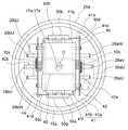
- FIG. FIG. 5 is a perspective view of the periphery of a control unit in the electric power steering apparatus according to Embodiment 1, as viewed from the non-output side.
- the electric power steering apparatus includes a control unit 1 and a motor 2.
- the control unit 1 is disposed on one side in the axial direction of the output shaft 21 of the motor 2 in one row with the motor 2 and is integrated with the motor 2.
- the electric power steering apparatus is disposed with the control unit 1 positioned upward with the axial direction of the output shaft 21 of the motor 2 as the vertical direction.
- the output of the motor 2 is output from the lower end portion of the output shaft 21 to, for example, a reduction gear (not shown). That is, in FIG. 2, the lower end side of the output shaft 21 is the output side, and the upper end side of the output shaft 21 is the opposite output side.
- the motor winding 24 includes two sets of three-phase motor windings 24a and 24b.
- the motor winding 24a is a first motor winding
- the motor winding 34b is a second motor winding.
- the control unit 1 includes control units 1a and 1b dedicated to the two sets of motor windings 24a and 24b, respectively.
- the control unit 1a includes a CPU 10a, a control board 4a which is a first control board on which various circuits are mounted, an inverter circuit 3a for supplying current to the motor 2, a power supply relay 5a, a filter 6a and the like.
- control unit 1b includes a CPU 10b, a control board 4b which is a second control board on which various circuits and the like are mounted, an inverter circuit 3b for supplying current to the motor 2, a power supply relay 5b, a filter 6b and the like.
- control unit 1 the circuit configuration of the control unit 1 will be described. Since the control units 1a and 1b have the same configuration, only the control unit 1a will be described here.
- Electric power is supplied from the battery 9 mounted on the vehicle to the control unit 1a via the ignition switch 7.
- Information from sensors 8 such as a vehicle speed sensor that detects the traveling speed of the vehicle and a torque sensor that detects a steering torque mounted near the steering wheel is transmitted to the CPU 10a.
- the CPU 10a calculates and outputs a current value which is a control amount for rotating the motor 2 based on the information.
- the drive circuit 11a receives an output signal of the CPU 10a, and outputs a drive signal for driving each switching element of the inverter circuit 3a to the inverter circuit 3a.
- the switching element of the inverter circuit 3a is a first switching element
- the switching element of the inverter circuit 3b is a second switching element.
- the drive circuit 11a is mounted on the control board 4a because only a small current flows as compared to the actual flow in the motor. Further, in the power supply system (+ B, ground), a filter 6a composed of a capacitor and a coil is inserted in order to suppress the release of noise due to PWM drive of the inverter circuit 3a. Furthermore, a power supply relay 5a for opening and closing the + B power supply line is inserted in the + B power supply line.
- the power supply relay 5a includes two switching elements and two parasitic diodes in the forward and reverse directions with respect to the current supply direction. The power supply relay 5a can forcibly shut off the power supply, for example, when a failure occurs in the inverter circuit 3a or the motor 2. Furthermore, when the battery 9 is reversely connected, the power supply relay 5a can shut off a line through which current flows, and also plays a role of so-called battery reverse connection protection.
- the inverter circuit 3a includes three circuit units 3U, 3V, 3W corresponding to the respective phases of the motor winding 24a.
- the circuit unit 3U has a relay function that opens and closes between the connection point of the upper arm switching element 31U, the lower arm switching element 32U, the upper and lower arm switching elements 31U and 32U, and the U1 phase winding.
- a switching element 34U The upper and lower arm switching elements 31U and 32U are PWM driven based on a command from the CPU 10a. Therefore, the smoothing capacitor 30U is connected in parallel with the upper and lower arm switching elements 31U and 32U for the purpose of noise suppression. Furthermore, a shunt resistor 33U for detecting the current flowing to the motor 2 is connected in series with the upper and lower arm switching elements 31U and 32U.
- the circuit units 3U, 3V, 3W have the same circuit configuration for each of the U1-phase, V1-phase and W1-phase windings, and can independently supply current to each winding.
- the ⁇ marks indicate connection terminals with the external device provided in the control units 1a and 1b.
- the potential difference between both ends of the shunt resistor 33, the voltage of the motor winding terminal, and the like are also input to the input circuit 12a.
- the CPU 10a also receives these pieces of information, calculates a difference from the detected value corresponding to the calculated current value, performs so-called feedback control, supplies a desired motor current, and assists the steering force.
- a drive signal of the switching element of the power supply relay 5a that operates as a relay that connects or disconnects the battery + B and the inverter circuit 3a is also output via the drive circuit 11a.
- the switching element of the power supply relay 5a is accompanied by heat generation because a large current flows. Therefore, the switching element of the power supply relay 5a can be included in the inverter circuit 3a and configured as a power module.
- the CPU 10a has an abnormality detection function of detecting abnormalities in the sensors 8, the drive circuit 11a, the inverter circuit 3a, the motor winding 24a and the like from the various types of input information.
- the CPU 10a turns off the switching elements for upper and lower arms of the phase and the switching elements for relay in response to the abnormality, for example, to cut off the current supply of only the phase in which the abnormality is detected.
- the CPU 10a can also turn off the switching element of the power supply relay 5a in order to originally shut off the power supply itself.
- the CPUs 10a and 10b are connected by the communication line 14 so as to be able to exchange information with each other, and particularly when an abnormality is detected, they are transmitted to the other party including the contents thereof.
- the motor 2 is a brushless motor provided with a motor winding 24 composed of two sets of delta-connected three-phase motor windings 24a and 24b.
- a rotation sensor for detecting the rotational position of the rotor 23 is mounted for the brushless motor.
- This rotation sensor is also composed of two sets of rotation sensors 17a and 17b in order to ensure redundancy.
- the rotation information from the rotation sensors 17a and 17b is input to the input circuits 12a and 12b of the control boards 4a and 4b, respectively.
- the motor is a three-phase motor, it may be a four-phase or higher polyphase motor. Further, although the motor winding is configured by delta connection of three-phase windings, it may be configured by star connection of three-phase windings.
- the motor is a three-phase brushless motor, but may be a two-pole two-pair brushed motor. Also, the motor winding can adopt a distributed winding or a concentrated winding.
- the motor may be a tandem motor having so-called two stators. However, any configuration may be used as long as it can output a desired motor rotational speed and torque with one set of windings or two sets of collaboration.
- the electric power steering apparatus is configured of two independent sets of circuitry, connectors, sensors, etc., to ensure redundancy.
- the motor 2 mainly includes an output shaft 21, a rotor 23, a stator 22, and a motor case 25 incorporating them.
- the motor case 25 is formed in a cylindrical shape with a bottom including a cylindrical portion 25a and a bottom portion 25b closing an opening on the output side of the cylindrical portion 25a.
- the motor case 25 is made of metal and is preferably made of aluminum in consideration of heat dissipation and the shape of the outer shape.
- the frame 29 is made of metal and in a disc shape. The frame 29 is inserted and held in the opening on the non-output side of the cylindrical portion 25a by press-fitting, shrink fitting, etc., and closes the opening on the non-output side of the cylindrical portion 25a.
- the frame 29 serves as a lid of the motor 2.
- the motor 2 is separated and independent of the control unit 1 by a frame 29.
- the stator 22 is inserted and held in the cylindrical portion 25 a of the motor case 25 by press fitting, shrink fitting, or the like.
- the stator 22 is provided with a three-phase motor winding 24.
- An annular wiring portion 27 is disposed on the output side of the frame 29 and in the vicinity of the motor winding 24.
- the end of the motor winding 24 is connected to the annular wiring portion 27.
- Three phase terminals 28a and 28b through which three-phase currents for driving the motor 2 flow are drawn out three by three from the annular wiring portion 27, penetrate the frame 29, and are drawn to the opposite side. That is, the three phase terminals 28a are connected to the windings of each phase of the motor winding 24a, and the three phase terminals 28b are connected to the windings of each phase of the motor winding 24b.
- the rotor 23 is fixed to the output shaft 21 supported by the bearing 26 a disposed at the axial center position of the frame 29 and the bearing 26 b disposed at the axial center position of the bottom 25 b, and is rotatable in the motor case 25 It is arranged.
- the rotor 23 is disposed in the stator 22 coaxially with the stator 22.
- a sensor rotor 18 is disposed at the end of the output shaft 21 projecting from the frame 29.
- a plurality of permanent magnets are arranged on the outer peripheral surface of the rotor 23 at a constant pitch so that N and S poles are alternately arranged in the circumferential direction.
- control unit 1 the configuration of the control unit 1 will be described with reference to FIGS. 2 and 3.
- the control unit 1 needs to make the area in the radial direction which is a direction orthogonal to the output shaft 21 equal to or smaller than that of the motor 2. Therefore, when mounting the control unit 1, a vertically mounted structure is adopted in which the main part is arranged parallel to the output shaft 21.
- the control unit 1 is covered with an outer layer of a resin housing 15. That is, the housing 15 constitutes the outer shell of the control unit 1.
- the housing 15 is formed in a bottomed cylindrical shape including a cylindrical peripheral wall 15a covering components of the control unit 1 and a bottom portion 15b closing one opening of the peripheral wall 15a.
- the end face on the non-output side of the bottom portion 15 b is a flat surface orthogonal to the axial direction of the output shaft 21.
- the housing 15 is fitted to the opening of the cylindrical portion 25a of the motor case 25 with the opening directed downward, and is attached to the cylindrical portion 25a using a screw (not shown).
- Power connectors 43a and 43b connected to the battery 9, which is an external power source, and a plurality of signal connectors 44a and 44b connected to the sensors 8 are disposed on the end surface of the bottom 15b of the housing 15 opposite to the output side. Furthermore, on the end face on the opposite side of the bottom 15b of the housing 15, filters 6a and 6b as large parts are mounted.
- the power connectors 43a and 43b are connectors through which a large current flows, and the signal connectors 44a and 44b are connectors through which a small current flows compared to the current flowing through the power connectors 43a and 43b.
- the power supply connector 43a is a first power supply connector
- the power supply connector 43b is a second power supply connector.
- the signal connector 44a is a first signal connector
- the signal connector 44b is a second signal connector.
- the heat sink 41, control boards 4a, 4b, power modules 50a, 50b incorporating a plurality of switching elements constituting the inverter circuits 3a, 3b, smoothing capacitors 30U, 30V, 30W, etc. are arranged inside the housing 15, the heat sink 41, control boards 4a, 4b, power modules 50a, 50b incorporating a plurality of switching elements constituting the inverter circuits 3a, 3b, smoothing capacitors 30U, 30V, 30W, etc. are arranged inside the housing 15, the heat sink 41, control boards 4a, 4b, power modules 50a, 50b incorporating a plurality of switching elements constituting the inverter circuits 3a, 3b, smoothing capacitors 30U, 30V, 30W, etc. are arranged inside the housing 15, the heat sink 41, control boards 4a, 4b, power modules 50a, 50b incorporating a plurality of switching elements constituting the inverter circuits 3a, 3b, smoothing capacitors 30U, 30V, 30W, etc. are
- the heat sink 41 is made of a high thermal conductive material such as aluminum or copper, and includes a disk-shaped base portion 41a and a rectangular column portion 41b standing upright in the central portion of the base portion 41a.
- the base portion 41 a of the heat sink 41 is disposed in the opening on the non-output side of the cylindrical portion 25 a.
- the base portion 41 a is pressed and held between the peripheral wall 15 a of the housing 15 attached to the cylindrical portion 25 a and the frame 29. Thereby, the heat sink 41 is fixed to the motor 2.
- the base portion 41 a is in contact with the inner peripheral wall surface of the cylindrical portion 25 a and in contact with the end surface on the non-output side of the frame 29.
- the column portion 41 b is disposed on the extension of the axis O of the output shaft 21 and disposed in the housing 15.
- the column part 41b has four arrangement parts 41d, 41e, 41f and 41g which consist of planes parallel to the axial direction of the output shaft 21.
- the recess 41 c is formed to open in the lower portion of the base portion 41 a and the side of the base portion 41 a of the column portion 41 b.
- a protruding end of the output shaft 21 from the frame 29, that is, an end on the non-output side of the output shaft 21 is inserted into the recess 41 c and located in the base portion 41 a.
- a sensor rotor 18 is attached to the end on the reverse output side of the output shaft 21.
- the sensor rotor 18 is composed of one or more pairs of magnet rotors.
- the circuit board 40 is disposed on the opposite surface of the sensor rotor 18 in the recess 41 c.
- the rotation sensors 17 a and 17 b are mounted on the circuit board 40 and arranged to face the sensor rotor 18.
- the rotation sensors 17a and 17b independently detect changes in the magnetic field caused by the rotation of the sensor rotor 18. Thus, the rotation sensors 17a and 17b independently detect the rotation of the output shaft 21.
- the rotation sensors 17a and 17b are incorporated in one package, but may be configured in one package.
- the circuit board 40 Since the circuit board 40 is disposed in the recess 41 c formed on the output side of the heat sink 41, the circuit board 40 has a smaller area than the control boards 4 a and 4 b. Power supply lines and signal lines of the rotation sensors 17a and 17b are separately drawn to the left and right in FIG. 2 through the wiring pattern of the circuit board 40, and are connected to the lower sides of the control boards 4a and 4b, respectively.
- the sensor rotor 18 and rotation sensor 17a, 17b were demonstrated by the magnetic sensor type, it does not restrict to this type, A resolver or a Hall sensor may be sufficient.
- the power module 50a is configured by resin sealing in a state in which the switching elements constituting the inverter circuit 3a are mounted on the wiring.
- the power module 50 b is configured by resin sealing in a state in which the switching elements constituting the inverter circuit 3 b are mounted on the wiring.
- the power modules 50a and 50b are attached in close contact with the pair of opposing placement portions 41f and 41g of the column portion 41b.
- the control board 4a is formed in a rectangular flat plate shape, and the CPU 10a, the drive circuit 11a, the input circuit 12a, the power supply circuit 13a and the like are mounted.
- the control board 4b is formed in a rectangular flat plate shape, and the CPU 10b, the drive circuit 11b, the input circuit 12b, the power supply circuit 13b and the like are mounted.
- the control boards 4a and 4b are attached in parallel to the other pair of arrangement portions 41d and 41e of the column portion 41b, respectively.
- the control board 4a is connected to the signal line 50c of the power module 50a. Therefore, the control board 4a is disposed on the placement portion 41d so as to protrude from the placement portion 41d toward the power module 50a.
- control substrate 4a and the power module 50a overlap each other as viewed in the direction orthogonal to the placement portion 41d.
- the control board 4b is connected to the signal line 50d of the power module 50b. Therefore, the control board 4b is disposed on the placement portion 41e so as to protrude from the placement portion 41e toward the power module 50b. As a result, the control substrate 4b and the power module 50b overlap when viewed from the direction orthogonal to the placement portion 41e.
- the signal line 44c of the signal connector 44a is drawn from the bottom 15b into the housing 15 and connected to the upper side of the control board 4a near the signal connector 44a.
- the signal line 44d of the signal connector 44b is drawn out from the bottom 15b into the housing 15 and connected to the upper side of the control board 4b near the signal connector 44b.
- the signal lines 44c and 44d are connected to the input circuits 12a and 12b of the control boards 4a and 4b.
- the power supply line 43c of the power supply connector 43a is pulled out of the bottom 15b into the housing 15 through the filter 6a.
- the power supply line 43 c drawn into the housing 15 is connected to the power supply line of the inverter circuit 3 a or the power supply relay 5 a via the bus bar of the relay member 42.
- power supply line 43d of power supply connector 43b is pulled out from bottom 15b into housing 15 through filter 6b.
- the power supply line 43 d drawn into the housing 15 is connected to the power supply line of the inverter circuit 3 b or the power supply relay 5 b via the bus bar of the relay member 42.
- the output terminal 51a of the inverter circuit 3a is drawn from the power module 50a toward the control substrate 4b.
- the output terminal 51 a is connected to the extension terminal 42 a via the bus bar of the relay member 42.
- the extension terminal 42a is drawn radially outward through the motor 2 side of the control board 4b.
- the output terminal 51b of the inverter circuit 3b is drawn from the power module 50b to the control substrate 4a side.
- the output terminal 51 b is connected to the extension terminal 42 b via the bus bar of the relay member 42.
- the extension terminal 42b is drawn radially outward through the motor 2 side of the control board 4a.
- phase terminal 28a connected to the winding of each phase of the motor winding 24a is pulled out into the housing 15 through the frame 29 and the base portion 41a.
- a phase terminal 28a (28aU, 28aV, 28aW) is connected to each of the extension terminals 42a on the motor 2 side of the control board 4b and radially outward.
- phase terminal 28b connected to the winding of each phase of motor winding 24b is pulled out into housing 15 through frame 29 and base portion 41a.
- a phase terminal 28b (28bU, 28bV, 28bW) is connected to each of the extension terminals 42b on the motor 2 side of the control board 4a and radially outward.
- the smoothing capacitors 30aU, 30aV, and 30aW are fixed to the support member 45a and vertically stacked radially outward of the control board 4b. That is, the smoothing capacitors 30aU, 30aV, and 30aW are arranged in a line in the axial direction of the output shaft 21, with the length direction being orthogonal to the axial direction of the output shaft 21 and parallel to the arrangement portion 41e.
- the smoothing capacitors 30aU, 30aV, and 30aW are arranged to be closer to the power connector 43a and the signal connector 44a as viewed from the opposite side of the output shaft 21 in the axial direction.
- the smoothing capacitors 30bU, 30bV, and 30bW are fixed to the support member 45b and vertically stacked in the radial direction of the control board 4a. That is, the smoothing capacitors 30bU, 30bV, and 30bW are arranged in a line in the axial direction of the output shaft 21 with the length direction orthogonal to the axial direction of the output shaft 21 and in parallel with the arrangement portion 41d.
- the smoothing capacitors 30bU, 30b, and 30b are disposed closer to the power connector 43b and the signal connector 44b as viewed from the opposite side of the output shaft 21 in the axial direction.
- each smoothing capacitor 30 is connected to the power supply line of the relay member 42 or the power supply line wired to the power modules 50a and 50b.
- the rectangular column 31 b of the heat sink 41, the control boards 4 a and 4 b, the power modules 50 a and 50 b, etc. are vertically disposed in the housing 15. Thus, the size of the electric power steering apparatus can be reduced.
- the control boards 4a and 4b are disposed one by one along each of a pair of opposing placement portions 41d and 41e of the column portion 41b.
- the power modules 50a and 50b are disposed one by one along each of the other pair of opposing placement portions 41f and 41g of the column portion 41b.
- the control substrate 4a and the power module 50a are disposed in the placement portion 41d in the radial direction, and the control substrate 4b and the power module 50b are disposed in the placement portion 41e in the radial direction.
- an increase in the radial dimension of the control unit 1 can be suppressed.
- the control unit 1 which does not exceed the diameter of the motor 2 can be realized.
- control unit 1 which does not exceed the diameter of the motor 2 can be realized, it is not necessary to reduce the width of the control boards 4a and 4b. As a result, the component mounting area can be secured without lengthening the control boards 4a and 4b, and an increase in the axial dimension of the control unit 1 can be suppressed. As a result, miniaturization of the device having two sets of circuit configurations can be achieved.
- the rectangular column portion 41 b of the heat sink 41 is located on the axis O of the output shaft 21.
- the heat sink 41 and the control boards 4a and 4b are arranged point-symmetrically with the axial center O of the output shaft 21 as the center of symmetry when viewed from the opposite output side of the output shaft 21 in the axial direction.
- the power connectors 43a, 43b and the signal connectors 44a, 44b are arranged at the very end of the device. Furthermore, the power connectors 43a and 43b and the signal connectors 44a and 44b are arranged point-symmetrically with the axis O of the output shaft 21 as the center of symmetry when viewed from the opposite output side of the output shaft 21 in the axial direction. . As a result, it is possible to mount circuits for two systems, and it becomes possible to miniaturize the product, in particular, to miniaturize the radial dimension.
- two sets of power modules 50a and 50b are point symmetric with the axial center O of the output shaft 21 as the symmetry center when viewed from the opposite output side of the output shaft 21 in the axial direction. It has become an arrangement. As a result, in addition to the miniaturization of the product, an effect of mutually canceling switching noise generated from a large current flowing through the two power modules 50a and 50b can be obtained. As a result, effects such as improvement of the angle detection accuracy of the rotation sensors 17a and 17b and reduction of radio noise can be obtained.
- control units 1a and 1b have the same shape and the same configuration separately and independently from each other, redundancy can be secured by two systems.
- the power modules 50a, 50b are arranged in a pair of arranging portions 41f, 41g constituted by short sides of a rectangular cross section orthogonal to the axis O of the column portion 41b.
- the control boards 4a and 4b are extendedly arranged on the side of the power modules 50a and 50b in the same pair in a pair of arranging portions 41d and 41e configured by long sides of a rectangular cross section orthogonal to the axis O of the column 41b.
- the control boards 4a and 4b project from the placement parts 51d and 41e to overlap the power modules 50a and 50b in the same set as viewed in the direction orthogonal to the placement parts 41d and 42e, thereby enlarging the mounting area. be able to.
- the sensor rotor 18 is mounted on the end of the output shaft 21 protruding from the frame 29 and disposed in a recess 41 c formed on the motor 2 side of the heat sink 41.
- the circuit board 40 is disposed on the surface of the recess 41 c facing the output shaft 21.
- the rotation sensors 17 a and 17 b are disposed on the circuit board 40 so as to face the sensor rotor 18. This makes it possible to miniaturize the device, in particular the axial dimension. Furthermore, since the rotation sensors 17a and 17b are disposed in the recess 41c, noise due to current on / off of the motor windings 24a and 24b is hardly received.
- the control boards 4a and 4b and the power modules 50a and 50b of the control units 1a and 1b are separated and independent.
- the control boards 4a and 4b are arranged point-symmetrically with the axial center O of the output shaft 21 as the center of symmetry when viewed from the opposite output side of the output shaft 21 in the axial direction.
- the phase terminals 28a and 28b of the motor windings 24a and 24b can be connected to any of the control boards 4a and 4b, and the assemblability is improved.
- two sets of connectors a power supply system and a signal system.
- they are branched into two sets of the power supply system and the signal system. May be
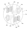
- FIG. 4 is a perspective view of the periphery of a control unit in an electric power steering apparatus according to Embodiment 2 of the present invention as viewed from the non-output side.
- the power module 50 a is held in close contact with the column portion 41 b of the heat sink 41 by the holding member 50 g.
- the power module 50b is held in close contact with the column portion 41b by the holding member 50h.
- the holding members 50g and 50h are a heat dissipating material, for example, a copper plate, they help to improve the heat dissipation of the power modules 50a and 50b.
- the control board 4a is disposed on the placement portion 41d so as to protrude on both sides in the width direction of the placement portion 41d of the column portion 41b.
- the overlap between the control substrate 4a and the power module 50a is made larger than the overlap between the control substrate 4a and the power module 50b when viewed from the direction orthogonal to the placement portion 41d.
- the control board 4b is disposed on the placement portion 41e so as to protrude on both sides in the width direction of the placement portion 41e of the column portion 41b.
- the overlap between the control substrate 4b and the power module 50b is made larger than the overlap between the control substrate 4b and the power module 50a when viewed from the direction orthogonal to the placement portion 41e. There is.
- the smoothing capacitors 30U, 30V, 30W are disposed outward in the radial direction of the control boards 4a, 4b so as to be close to the motor 2 side in the axial direction of the output shaft 21. Thereby, the electrical connection length between the terminals of the smoothing capacitors 30U, 30V, 30W and the power supply line of the relay member 42 or the power modules 50a, 50b can be shortened, and there is a noise suppression effect.
- the heat sink 41, the control boards 4a and 4b, the power modules 50a and 50b, the power connectors 43a and 43b, the signal connectors 44a and 44b, and the smoothing capacitor 30 When viewed from the side, it is arranged point-symmetrically with the axis O of the output shaft 21 as the center of symmetry.
- the second embodiment is also configured in the same manner as the first embodiment. Furthermore, in the second embodiment, the control boards 4a and 4b are shaped so as to protrude on both sides in the width direction of the placement portions 41d and 41e. As a result, compared to the first embodiment, the mounting area of the control boards 4a and 4b can be expanded, and more parts can be mounted without increasing the size of the control unit.
- the pillar portion 41 b of the heat sink 41 is formed in a rectangular shape in top view as viewed from the outside in the axial direction of the output shaft 21.
- the pillar portion 41 b is not limited to a rectangular top view, and may be a polygon having at least four arrangement portions in which two control boards and two power modules are arranged.
- FIG. 5 is a perspective view of the control unit in the electric power steering apparatus according to Embodiment 3 of the present invention as viewed from the non-output side
- FIG. 6 is an illustration of the electric power steering apparatus according to Embodiment 3 of the present invention. It is an end elevation seen from the output side.
- the pillar portion 41b of the heat sink 41 is configured such that the side of the arranging portion 41g constituted by one short side of the rectangle is a long side when viewed from the opposite output side of the output shaft 21 in the axial direction. It projects to the side of the arranged portion 41d. Furthermore, when viewed from the opposite output side in the axial direction of the output shaft 21, the column portion 41b of the heat sink 41 is configured such that the other side of the rectangular arrangement portion 41f is formed by the other long side It is made to protrude to the arrangement
- the end of the mounting portion 41d of the heat sink 41 on the side of the placement portion 41g of the placement portion 41d protrudes to the opposite side to the placement portion 41e
- the end of the placement portion 41e on the side of the placement portion 41f is opposite to the placement portion 41d. It has a shape that protrudes to the side.
- the control boards 4a and 4b are disposed in areas excluding the projecting portions of the placement portions 41d and 41e, respectively.
- the power module 50a is disposed on the placement portion 41f so as to be shifted to the protrusion side and away from the control substrate 4a.
- the power module 50b is disposed on the placement portion 41g so as to be shifted to the protrusion side and away from the control substrate 4b.
- the control boards 4a and 4b are disposed apart from the disposition portions 41d and 41e of the column portion 41b.
- the heat generating component 53 mounted on the control boards 4a and 4b is in contact with the heat radiating portion 54 protruding from the placement portions 41d and 41e via a heat radiating member such as a bond or a sheet having high thermal conductivity, for example.
- a heat radiating member such as a bond or a sheet having high thermal conductivity, for example.
- Power supply connectors 43a and 43b and signal connectors 44a and 44b are disposed on the outer surface which is the surface on the opposite side of the bottom 15b of the housing 15, as shown in FIG.
- the power supply line 43d which is a group of terminals extended from the power supply connector 43b, is put together and extends through the inside of the bottom 15b of the housing 15 to a substantially central portion of the bottom 15b. Pulled out inside. Furthermore, the power supply line 43d is supported on the bottom 15b by the support member 45b, extends radially inward from the inner surface of the bottom 15b, and is connected to the power supply line of the control board 4a and the relay member 42c.
- a signal line 44d which is a group of terminals extended from the signal connector 44a, is extended through the inside of the bottom 15b of the housing 15 to a radially outward position of the lead-out portion of the power supply line 43d into the housing 15, where It is pulled out into the housing 15 from the bottom 15 b. Furthermore, the signal line 44d is supported on the bottom 15b by the support member 45b, extends radially inward from the inner surface of the bottom 15b, and is connected to the signal line of the control board 4a.
- the power supply line 43c which is a group of terminals extended from the power supply connector 43a, is put together and extends through the inside of the bottom 15b of the housing 15 to a substantially central portion of the bottom 15b. Pulled out inside. Further, the power supply line 43c is supported on the bottom 15b by the support member 45a, extends radially inward from the inner surface of the bottom 15b, and is connected to the power supply line of the control board 4b and the relay member 42d.
- a signal line 44c which is a group of terminals extended from the signal connector 44b, is extended through the inside of the bottom 15b of the housing 15 to a radially outward position of the lead-out portion of the power supply line 43c into the housing 15, where It is pulled out into the housing 15 from the bottom 15 b. Furthermore, the signal line 44c is supported on the bottom 15b by the support member 45a, extends radially inward from the inner surface of the bottom 15b, and is connected to the signal line of the control board 4b.
- the power connectors 43a and 43b, the power lines 43c and 43d, the signal connectors 44a and 44b, the signal lines 44c and 44d, and the support members 45a and 45b are viewed from the opposite side of the output shaft 21 in the axial direction. It is arranged point-symmetrically with the axis O as the center of symmetry. Since the power supply lines 43c and 43d and the signal lines 44c and 44d are arranged substantially in a straight line, there is also an effect that the workability and the assemblability can be standardized.
- the phase terminals 28aU, 28aV, 28aW, 28bU, 28bV and 28bW of the motor windings 24a and 24b are the output shaft 21 when viewed from the non-output side in the axial direction of the output shaft 21. It is point symmetrical arrangement centering on the axis center O of.
- the phase terminals 28aU, 28aV, 28aW, 28bU, 28bV and 28bW are provided radially outward of the control boards 4a and 4b and on the motor 2 side of the control boards 4a and 4b and at output terminals from the power modules 50a and 50b. Connected to the extension terminal.
- the power connectors 43a and 43b and the signal connectors 44a and 44b have the axis O of the output shaft 21 as the symmetry center when viewed from the opposite output side of the output shaft 21 in the axial direction. It is arranged in point symmetry.
- a power supply line 43c extending from a terminal of the power supply connector 43a and a signal line 44c extending from each terminal of the signal connector 44b are respectively put together and taken out as a terminal group 46b into the housing 15 to be connected And connected to the signal line.
- the power supply line 43d of the power supply connector 43b and the signal line 44d of the signal connector 44a are also drawn into the housing 15 as a terminal group 46a and connected to the power supply line and the signal line to be connected.
- main components inside and outside the housing 15 are point-symmetrically disposed centering on the axial center O of the output shaft 21. .
- the power supply connector and the signal connector are vertically spaced from each other in the drawing, but they may be horizontally spaced from each other.
- FIG. 7 is a perspective view of the area around the control unit in the electric power steering apparatus according to Embodiment 4 of the present invention as viewed from the opposite side.
- control boards 4 a and 4 b are disposed at a pair of opposing placement portions 41 d and 41 e of the column portion 41 b of the heat sink 41.
- the power modules 50 a and 50 b are disposed in another pair of opposing placement portions 41 f and 41 g of the column portion 41 b of the heat sink 41.
- the control board 4b and the power module 50b are smaller than the control board 4a and the power module 50a.
- the other configuration is the same as that of the first embodiment.
- power module 50a corresponds to a system having a large current capacity for driving motor 2
- power module 50b corresponds to a system having a small current capacity for driving motor 2.
- the electric power steering apparatus may correspond to a system in which the control unit 1b is subordinately used by using the control unit 1a when normal.
- control boards 4 a and 4 b are disposed on the pair of opposing placement portions 41 d and 41 e of the pillars 41 b of the heat sink 41, and the power modules 50 a and 50 b are of the pillars 41 b of the heat sink 41. It is arrange
- the motor is described as a three-phase motor, but it may be a multi-phase winding motor having three or more phases. Further, although the above embodiments are described using two sets of three-phase motor windings, one set of three-phase motor windings may be used.
- the first power module incorporating the switching elements constituting the circuit units 3U and 3V, the combination of the first control board outputting a control signal to those switching elements, the circuit unit 3W and the power supply relay are switched
- a second power module having a built-in element and a set of a second control board for outputting a control signal to the switching elements are configured.
- first control board and the second control board are disposed one by one along each of the pair of disposition portions 41d and 41e of the pillar portion 41b, and the first power module and the second power module are disposed It may be disposed one by one along each of the other pair of disposition portions 41f, 41g of the portion 41b.
Landscapes
- Engineering & Computer Science (AREA)
- Power Engineering (AREA)
- Chemical & Material Sciences (AREA)
- Combustion & Propulsion (AREA)
- Transportation (AREA)
- Mechanical Engineering (AREA)
- Microelectronics & Electronic Packaging (AREA)
- Power Steering Mechanism (AREA)
- Inverter Devices (AREA)
Abstract
本発明の電動パワーステアリング装置は、モータは、第1モータ巻線と第2モータ巻線とを備え、制御ユニットは、上記第1モータ巻線に電流を供給する第1パワーモジュールと、上記第1パワーモジュールに制御信号を出力する第1制御基板と、上記第2モータ巻線に電流を供給する第2パワーモジュールと、上記第2パワーモジュールに制御信号を出力する第2制御基板と、ヒートシンクと、を備え、上記ヒートシンクは、上記モータの出力軸の軸心の延長線上に配置され、上記出力軸の軸方向と平行な平面からなる複数の配置部を備える柱部を有し、上記第1制御基板と上記第2制御基板とが、相対する一対の配置部のそれぞれに沿って1つずつ配置され、上記第1パワーモジュールと上記第2パワーモジュールとが、他の相対する一対の配置部のそれぞれに沿って1つずつ配置されている。
Description
この発明は、モータと制御ユニットが一体化された電動パワーステアリング装置に関し、特に2組のモータ駆動回路を備えた制御ユニットの構造に関する。
従来の駆動装置は、モータの出力軸の軸方向に同軸に配置されたモータと制御ユニットとを一体化して構成されていた。このような従来の駆動装置において、モータケース内にステータ、ロータなどが内蔵され、モータの近傍に配置された制御ユニットが主要構成部品を軸方向に積層して組立てられた構造が散見されている。また、冗長性を考慮して、モータ巻線を2組とし、これらを駆動するいわゆるインバータ回路および制御基板も独立に2組備えた従来装置も現れている(例えば、特許文献1参照)。
特許文献1に開示された従来装置は、モータと、モータの出力軸の出力側と反対側のモータ端部に配置された制御ユニットと、を一体化した構造となっている。このように構成された従来装置の車両への装着を考慮した場合、車両への取付け上の規制から、制御ユニットがモータの径方向に広がると車両搭載が困難となることが多い。一方、従来装置のモータの出力軸方向の長さは、比較的長くても許容できることが多い。これらのことから、従来装置の車両への装着を考慮した場合、制御ユニットの径方向の面積は、モータと同等、又は小さくする必要がある。そこで、従来装置においては、制御ユニットを構成するパワーモジュールおよびヒートシンクが、出力軸の軸方向に平行に、すなわち縦置きに配置されていた。一方、制御基板は、出力軸の軸方向に垂直に、すなわち横置きに配置されていた。そして、制御基板は、モータと制御ユニットとを分断する境界になっていた。なお、モータの出力軸の出力側と反対側を反出力側とする。
従来装置では、2組のパワーモジュールと、パワーモジュールのそれぞれを独立に駆動する2組の制御回路と、を備えており、それらを制御ユニットの外殻に内蔵するために、2組のパワーモジュールと2組の制御基板とを、ヒートシンクの配置面に縦置きに配置する構成としていた。
しかし、従来装置では、ヒートシンクに形成された相対する一対の配置面のそれぞれに、制御基板とパワーモジュールとを径方向に重ねて配置していた。そのため、製品の大型化、特に径方向の大型化につながるという課題があった。一方、制御基板の幅を小さくすることで、径方向の大型化を抑えることができる。しかし、この場合、制御基板の部品実装面積を確保するためには、制御基板の幅を小さくすることによる部品実装面積の縮小を、制御基板の長さを長くすることで補足する必要がある。その結果、製品の軸方向の大型化をもたらす。
しかし、従来装置では、ヒートシンクに形成された相対する一対の配置面のそれぞれに、制御基板とパワーモジュールとを径方向に重ねて配置していた。そのため、製品の大型化、特に径方向の大型化につながるという課題があった。一方、制御基板の幅を小さくすることで、径方向の大型化を抑えることができる。しかし、この場合、制御基板の部品実装面積を確保するためには、制御基板の幅を小さくすることによる部品実装面積の縮小を、制御基板の長さを長くすることで補足する必要がある。その結果、製品の軸方向の大型化をもたらす。
この発明は、上記課題を解決するためになされたもので、小型化が可能な、冗長性を考慮した2組の回路構成とする電動パワーステアリング装置を提供する。
本発明による電動パワーステアリング装置は、モータと、上記モータの出力軸の軸方向に配置されて、上記モータと一体化された制御ユニットと、を備える。上記モータは、第1モータ巻線と、第2モータ巻線と、を備え、制御ユニットは、上記第1モータ巻線に電流を供給する複数の第1スイッチング素子を有する第1パワーモジュールと、上記複数の第1スイッチング素子に制御信号を出力する第1制御基板と、上記第2モータ巻線に電流を供給する複数の第2スイッチング素子を有する第2パワーモジュールと、上記複数の第2スイッチング素子に制御信号を出力する第2制御基板と、上記制御ユニットでの発熱を放散するヒートシンクと、上記制御ユニットの外殻を構成するハウジングと、を備える。上記ヒートシンクは、上記ハウジング内の上記出力軸の軸心の延長線上を上記出力軸の軸方向に延びる柱部を備え、上記柱部は、上記出力軸の軸方向と平行な平面からなる複数の配置部を有し、上記第1制御基板と上記第2制御基板とが、上記複数の配置部の中の相対する一対の配置部のそれぞれに沿って1つずつ配置され、上記第1パワーモジュールと上記第2パワーモジュールとが、上記複数の配置部の中の他の相対する一対の配置部のそれぞれに沿って1つずつ配置されている。
この発明によれば、柱部、第1制御基板および第2制御基板を縦置き配置として、ハウジング内の有効面積を拡大した上で、第1制御基板と第2制御基板とが、複数の配置部の中の相対する一対の配置部のそれぞれに沿って1つずつ配置され、第1パワーモジュールと第2パワーモジュールとが、複数の配置部の中の他の相対する一対の配置部のそれぞれに沿って1つずつ配置されている。これにより、制御ユニットの径方向寸法の増大が抑えられ、モータの径を超えない制御ユニットを実現できる。さらに、第1制御基板および第2制御基板の長さを長くして、部品実装面積を確保する必要がなく、制御ユニットの軸方向寸法の増大が抑えられる。その結果、2組の回路構成とする装置の小型化を図ることができる。
実施の形態1.
図1は、この発明の実施の形態1に係る電動パワーステアリング装置の回路図、図2は、この発明の実施の形態1に係る電動パワーステアリング装置を示す断面図、図3は、この発明の実施の形態1に係る電動パワーステアリング装置における制御ユニット周りを反出力側から見た透視図である。
図1は、この発明の実施の形態1に係る電動パワーステアリング装置の回路図、図2は、この発明の実施の形態1に係る電動パワーステアリング装置を示す断面図、図3は、この発明の実施の形態1に係る電動パワーステアリング装置における制御ユニット周りを反出力側から見た透視図である。
図1および図2において、電動パワーステアリング装置は、制御ユニット1と、モータ2と、を備えている。制御ユニット1は、モータ2の出力軸21の軸方向の一側に、モータ2と1列に配置されて、モータ2と一体化されている。そして、電動パワーステアリング装置は、モータ2の出力軸21の軸方向を上下方向として、かつ制御ユニット1を上方に位置させて、配置される。モータ2の出力が、出力軸21の下端部から、例えば減速機(図示せず)に出力される。つまり、図2において、出力軸21の下端側が出力側、出力軸21の上端側が反出力側となる。
モータ巻線24は、2組の三相のモータ巻線24a,24bを備える。なお、モータ巻線24aは第1モータ巻線であり、モータ巻線34bは第2モータ巻線である。制御ユニット1は、2組のモータ巻線24a,24bのそれぞれに専用の制御ユニット1a,1bを備える。制御ユニット1aは、CPU10a、各種回路などが搭載された第1の制御基板である制御基板4a、モータ2に電流を供給するインバータ回路3a、電源用リレー5a、フィルタ6aなどを備える。同様に、制御ユニット1bは、CPU10b、各種回路などが搭載された第2制御基板である制御基板4b、モータ2に電流を供給するインバータ回路3b、電源用リレー5b、フィルタ6bなどを備える。
まず、制御ユニット1の回路構成について、説明する。制御ユニット1a,1bは、同一の構成であるので、ここでは、制御ユニット1aについてのみ説明する。
車両に搭載されたバッテリ9からイグニッションスイッチ7を介して電力が制御ユニット1aに供給される。車両の走行速度を検出する車速センサ、ハンドルの近傍に搭載される操舵トルクを検出するトルクセンサなどのセンサ類8からの情報が、CPU10aに伝達される。CPU10aは、これらの情報に基づいてモータ2を回転させるための制御量である電流値を演算し、出力する。駆動回路11aは、CPU10aの出力信号を受け、インバータ回路3aの各スイッチング素子を駆動する駆動信号をインバータ回路3aに出力する。なお、インバータ回路3aのスイッチング素子が第1スイッチング素子であり、インバータ回路3bのスイッチング素子が第2スイッチング素子である。
駆動回路11aは、モータに実際に流れる比較して小電流しか流れないので、制御基板4aに実装されているが、インバータ回路3aに配置することもできる。
また、電源系(+B、グランド)には、インバータ回路3aのPWM駆動によるノイズの放出を抑制するために、コンデンサとコイルとからなるフィルタ6aが挿入されている。さらに、+B電源ラインを開閉する電源用リレー5aが、+B電源ラインに挿入されている。この電源用リレー5aは、2つのスイッチング素子と、電流供給方向に対して順方向と逆方向の2つの寄生ダイオードと、を備える。電源用リレー5aは、インバータ回路3a又はモータ2に故障が発生した場合などに、電力供給を強制的に遮断することができる。さらに、電源用リレー5aは、バッテリ9を逆接続した場合に、電流が流れるラインを遮断することができ、いわゆるバッテリ逆接続保護の役目も担っている。
また、電源系(+B、グランド)には、インバータ回路3aのPWM駆動によるノイズの放出を抑制するために、コンデンサとコイルとからなるフィルタ6aが挿入されている。さらに、+B電源ラインを開閉する電源用リレー5aが、+B電源ラインに挿入されている。この電源用リレー5aは、2つのスイッチング素子と、電流供給方向に対して順方向と逆方向の2つの寄生ダイオードと、を備える。電源用リレー5aは、インバータ回路3a又はモータ2に故障が発生した場合などに、電力供給を強制的に遮断することができる。さらに、電源用リレー5aは、バッテリ9を逆接続した場合に、電流が流れるラインを遮断することができ、いわゆるバッテリ逆接続保護の役目も担っている。
インバータ回路3aは、モータ巻線24aの各相に対応する3つの回路部3U,3V,3Wを備える。ここで、3つの回路部3U,3V,3Wは、同一の構成であるので、回路部3Uについてのみ説明する。回路部3Uは、上アーム用スイッチング素子31Uと、下アーム用スイッチング素子32Uと、上下アーム用スイッチング素子31U,32Uの接続点とU1相の巻線との間を開閉するリレー機能を有したリレー用スイッチング素子34Uと、を備えている。上下アーム用スイッチング素子31U,32Uは、CPU10aの指令に基づきPWM駆動される。このため、ノイズ抑制の目的で、平滑コンデンサ30Uが、上下アーム用スイッチング素子31U,32Uと並列に接続されている。さらに、モータ2に流れる電流を検出するためのシャント抵抗33Uが、上下アーム用スイッチング素子31U,32Uと直列に接続されている。
回路部3U,3V,3Wは、U1相、V1相およびW1相の各巻線に対して同一の回路構成を有しており、各巻線に独立に電流供給を行える。なお、図1中○印は、制御ユニット1a、1bに設けられた、外部機器との接続端子を示す。
また、シャント抵抗33の両端間の電位差、モータ巻線端子の電圧なども入力回路12aに入力される。CPU10aは、これらの情報も入力され、演算した電流値に対応する検出値との差異を演算して、いわゆるフィードバック制御を行うことで、所望のモータ電流を供給し、操舵力をアシストする。さらに、バッテリ+Bとインバータ回路3aとを接続または遮断するリレーとして作動する電源用リレー5aのスイッチング素子の駆動信号も、駆動回路11a介して出力される。なお、電源用リレー5aのスイッチンング素子は、大電流が流れるため発熱を伴う。そこで、電源用リレー5aのスイッチンング素子は、インバータ回路3aに包含させて、パワーモジュールとして構成することもできる。
CPU10aは、入力した各種の情報から、センサ類8、駆動回路11a、インバータ回路3a、モータ巻線24aなどの異常を検出する異常検出機能を有する。CPU10aは、異常を検出した場合、その異常に応じて、例えば異常が検出された相のみの電流供給を遮断するために、当該相の上下アーム用スイッチング素子、リレー用スイッチング素子をオフする。また、CPU10aは、電源自体を元から遮断するために電源用リレー5aのスイッチング素子をオフすることも可能である。さらに、CPU10a、10bは、互いに情報を授受できるように通信ライン14で接続されており、特に異常検出した場合、その内容も含めて相手方に送信する。
ここで、モータ2は、デルタ結線された2組の3相のモータ巻線24a,24bからなるモータ巻線24を備えたブラシレスモータである。ブラシレスモータのために、ロータ23の回転位置を検出するための回転センサが搭載されている。この回転センサも、冗長性を確保するために2組の回転センサ17a,17bから構成されている。回転センサ17a,17bからの回転情報は、それぞれ制御基板4a、4bの入力回路12a、12bに入力される。
なお、モータは、三相モータとしているが、四相以上の多相モータでもよい。また、モータ巻線は、三相の巻線をデルタ結線して構成されているが、三相の巻線をスター結線して構成してもよい。また、モータは、三相のブラシレスモータとしているが、2極2対のブラシ付きモータであってもよい。また、モータ巻線は、分布巻巻線または集中巻巻線を採用できる。また、モータは、いわゆる2個のステータを有するタンデムモータであってもよい。ただし、1組の巻線のみでも、2組協働でも所望のモータ回転数、トルクが出力できる構成であればよい。
以上のように、本電動パワーステアリング装置は、回路網、コネクタ、センサなどがすべて独立した2組で構成され、冗長性を確保する。
つぎに、モータ2の構成について、図2を用いて説明する。
モータ2は、出力軸21、ロータ23、ステータ22、それらを内蔵するモータケース25から主に構成される。
モータケース25は、円筒部25aと、円筒部25aの出力側の開口を塞ぐ底部25bと、からなる有底円筒状に構成されている。モータケース25は、金属製であり、放熱性、および外形の形状を考慮すると、アルミニウムで作製することが望ましい。フレーム29が、金属で円盤状に作製されている。フレーム29は、円筒部25aの反出力側の開口内に、圧入、焼き嵌めなどにより、挿入、保持され、円筒部25aの反出力側の開口を塞いでいる。フレーム29は、モータ2の蓋の役目を有する。モータ2は、フレーム29により、制御ユニット1と分離、独立されている。
ステータ22は、モータケース25の円筒部25a内に、圧入、焼き嵌めなどにより、挿入、保持されている。ステータ22は、3相のモータ巻線24を備える。環状配線部27が、フレーム29の出力側に、かつモータ巻線24の近傍に配置されている。モータ巻線24の端末が、環状配線部27に接続されている。モータ2を駆動するための3相の電流が流れる相端子28a,28bが、環状配線部27から3本ずつ引き出され、フレーム29を貫通して、反出力側に引き出されている。つまり、3本の相端子28aがモータ巻線24aの各相の巻線に接続され、3本の相端子28bがモータ巻線24bの各相の巻線に接続される。
ロータ23は、フレーム29の軸心位置に配置された軸受26aと底部25bの軸心位置に配置された軸受26bとに支持された出力軸21に固着されて、モータケース25内に回転可能に配置されている。ロータ23は、ステータ22内に、ステータ22と同軸に配置されている。センサロータ18が、出力軸21のフレーム29からの突出端に配置されている。なお、図示していないが、永久磁石が、周方向にN極とS極とが交互に並ぶように、一定のピッチで、ロータ23の外周面に複数配置されている。
つぎに、制御ユニット1の構成について、図2および図3を用いて説明する。
制御ユニット1は、出力軸21と直交する方向である径方向の面積をモータ2と同等、又は小さくする必要がある。そこで、制御ユニット1の取り付けに当たっては、その主要部位を出力軸21と平行に配置する縦置き構造が採用されている。
制御ユニット1は、その外層が樹脂製のハウジング15により覆われている。すなわち、ハウジング15は、制御ユニット1の外殻を構成する。ハウジング15は、制御ユニット1の構成部品を覆う円筒状の周壁15aと、周壁15aの一側開口を塞ぐ底部15bと、からなる有底円筒状に形成されている。底部15bの反出力側の端面は、出力軸21の軸方向と直交する平坦面となっている。ハウジング15は、開口を下方に向けて、モータケース25の円筒部25aの開口に嵌め合わされ、ねじ(図示せず)を用いて円筒部25aに取り付けられている。ハウジング15の底部15bの反出力側の端面には、外部電源であるバッテリ9と接続する電源コネクタ43a,43b、およびセンサ類8と接続する複数の信号コネクタ44a,44bが配置されている。さらに、ハウジング15の底部15bの反出力側の端面には、大型部品であるフィルタ6a,6bなどが搭載される。電源コネクタ43a,43bは、大電流が流れるコネクタであり、信号コネクタ44a,44bは、電源コネクタ43a,43bに流れる電流と比較して小電流が流れるコネクタである。なお、電源コネクタ43aが、第1電源コネクタであり、電源コネクタ43bが、第2電源コネクタである。また、信号コネクタ44aが、第1信号コネクタであり、信号コネクタ44bが、第2信号コネクタである。
ハウジング15の内部には、ヒートシンク41、制御基板4a,4b、インバータ回路3a,3bを構成する複数のスイッチング素子が内蔵されたパワーモジュール50a,50b、平滑コンデンサ30U,30V,30Wなどが配置される。なお、パワーモジュール50aが第1パワーモジュールであり、パワーモジュール50bが第2パワーモジュールである。
ヒートシンク41は、アルミニウム、銅などの高熱伝導材料で作製され、円盤状のベース部41aと、ベース部41aの中央部に直立する直方体の柱部41bと、を備える。ヒートシンク41のベース部41aが、円筒部25aの反出力側の開口内に配置される。ベース部41aは、円筒部25aに取り付けられたハウジング15の周壁15aとフレーム29との間に加圧挟持される。これにより、ヒートシンク41は、モータ2に固定される。ベース部41aは、円筒部25aの内周壁面に接し、フレーム29の反出力側の端面に接する。柱部41bは、出力軸21の軸心Oの延長線上に位置して、ハウジング15内に配置されている。柱部41bは、出力軸21の軸方向と平行な平面からなる4つの配置部41d,41e,41f,41gを有する。
凹部41cが、ベース部41aの下部と柱部41bのベース部41a側とに開口するように形成されている。出力軸21のフレーム29からの突出端、すなわち出力軸21の反出力側の端部が、凹部41cに挿入されて、ベース部41a内に位置している。センサロータ18が、出力軸21の反出力側の端部に装着される。センサロータ18は、1対、又は複数対の磁石ロータにより構成される。回路基板40が、凹部41c内のセンサロータ18の対向面に配置されている。回転センサ17a、17bが、回路基板40に搭載されて、センサロータ18に対向するように配置されている。回転センサ17a,17bは、センサロータ18が回転することによる磁界の変化をそれぞれ独立に検出する。これにより、回転センサ17a,17bが、出力軸21の回転を独立して検出する。回転センサ17a、17bは、1つのパッケージに内蔵されているが、それぞれ、1パッケージで構成されてもよい。
回路基板40は、ヒートシンク41の出力側に形成された凹部41c内に配置されているため、制御基板4a、4bと比較して小面積である。回転センサ17a、17bの電源ラインおよび信号ラインが、回路基板40の配線パターンを介して図2中左右に分かれて引き出され、制御基板4a、4bの下辺にそれぞれ接続される。なお、センサロータ18および回転センサ17a、17bは、磁気センサタイプで説明したが、このタイプに限るものではなく、レゾルバであってもホールセンサであってもよい。
パワーモジュール50aは、インバータ回路3aを構成するスイッチング素子が、配線に実装された状態で樹脂封止されて構成される。パワーモジュール50bは、インバータ回路3bを構成するスイッチング素子が、配線に実装された状態で樹脂封止されて構成される。パワーモジュール50a,50bは、柱部41bの相対する一対の配置部41f,41gのそれぞれに密着状態に取り付けられる。
制御基板4aは、矩形平板状に形成され、CPU10a、駆動回路11a、入力回路12a、電源回路13aなどが実装される。同様に、制御基板4bは、矩形平板状に形成され、CPU10b、駆動回路11b、入力回路12b、電源回路13bなどが実装される。制御基板4a,4bは、柱部41bの相対するもう一対の配置部41d,41eのそれぞれに平行な状態で取り付けられる。制御基板4aは、パワーモジュール50aの信号ライン50cと接続される。そこで、制御基板4aは、配置部41dからパワーモジュール50a側に突出するようにして、配置部41dに配置される。これにより、配置部41dと直交する方向から見て、制御基板4aとパワーモジュール50aとが重なっている。制御基板4bは、パワーモジュール50bの信号ライン50dと接続される。そこで、制御基板4bは、配置部41eからパワーモジュール50b側に突出するようにして、配置部41eに配置される。これにより、配置部41eと直交する方向から見て、制御基板4bとパワーモジュール50bとが重なっている。
信号コネクタ44aの信号ライン44cが、底部15bからハウジング15内に引き出されて、制御基板4aの信号コネクタ44aに近い上辺に接続される。一方、信号コネクタ44bの信号ライン44dが、底部15bからハウジング15内に引き出されて、制御基板4bの信号コネクタ44bに近い上辺に接続される。これにより、信号ライン44c,44dが、制御基板4a,4bの入力回路12a,12bに接続される。
電源コネクタ43aの電源ライン43cが、フィルタ6aを介して底部15bからハウジング15内に引き出される。ハウジング15内に引き出された電源ライン43cが、中継部材42のバスバーを介して、インバータ回路3aまたは電源用リレー5aの電源ラインに接続される。一方、電源コネクタ43bの電源ライン43dが、フィルタ6bを介して底部15bからハウジング15内に引き出される。ハウジング15内に引き出された電源ライン43dが、中継部材42のバスバーを介して、インバータ回路3bまたは電源用リレー5bの電源ラインに接続される。
インバータ回路3aの出力端子51aは、パワーモジュール50aから制御基板4b側に引き出される。出力端子51aは、中継部材42のバスバーを介して延長ターミナル42aに接続される。延長ターミナル42aは、制御基板4bのモータ2側を通って径方向外方に引き出される。一方、インバータ回路3bの出力端子51bは、パワーモジュール50bから制御基板4a側に引き出される。出力端子51bは、中継部材42のバスバーを介して延長ターミナル42bに接続される。延長ターミナル42bは、制御基板4aのモータ2側を通って径方向外方に引き出される。
モータ巻線24aの各相の巻線に接続された相端子28aが、フレーム29およびベース部41aを貫通してハウジング15内に引き出される。相端子28a(28aU,28aV,28aW)が、制御基板4bのモータ2側、かつ径方向外方で、延長ターミナル42aのそれぞれに接続される。一方、モータ巻線24bの各相の巻線に接続された相端子28bが、フレーム29およびベース部41aを貫通してハウジング15内に引き出される。相端子28b(28bU,28bV,28bW)が、制御基板4aのモータ2側、かつ径方向外方で、延長ターミナル42bのそれぞれに接続される。
平滑コンデンサ30aU、30aV、30aWが、支持部材45aに固定されて、制御基板4bの径方向外方に縦積み配置されている。つまり、平滑コンデンサ30aU、30aV、30aWは、長さ方向を出力軸21の軸方向と直交させ、かつ配置部41eと平行にして、出力軸21の軸方向に1列に配列される。平滑コンデンサ30aU、30aV、30aWは、出力軸21の軸方向の反出力側から見て、電源コネクタ43aと信号コネクタ44aの側に近づくように配置される。
一方、平滑コンデンサ30bU、30bV、30bWが、支持部材45bに固定されて、制御基板4aの径方向外方に縦積み配置されている。つまり、平滑コンデンサ30bU、30bV、30bWは、長さ方向を出力軸21の軸方向と直交させ、かつ配置部41dと平行にして、出力軸21の軸方向に1列に配列される。平滑コンデンサ30bU、30b、30bは、出力軸21の軸方向の反出力側から見て、電源コネクタ43bと信号コネクタ44bの側に近づくように配置される。
なお、各平滑コンデンサ30の端子は、中継部材42の電源ライン、又はパワーモジュール50a、50bに配線された電源ラインに接続される。
つぎに、このように構成された装置により得られる効果を説明する。
制御ユニット1においては、ヒートシンク41の直方体の柱部41b、制御基板4a,4b、パワーモジュール50a,50bなどが、ハウジング15内に縦置きに配置されている。これにより、電動パワーステアリング装置の小型化が図られる。
制御基板4a,4bが、柱部41bの相対する一対の配置部41d,41eのそれぞれに沿って1つずつ配置されている。パワーモジュール50a,50bが、柱部41bの他の相対する一対の配置部41f,41gのそれぞれに沿って1つずつ配置されている。この構成は、制御基板4aとパワーモジュール50aを径方向に重ねて配置部41dに配置し、かつ制御基板4bとパワーモジュール50bを径方向に重ねて配置部41eに配置する従来装置の構成に比べて、制御ユニット1の径方向寸法の増大を抑えることができる。その結果、モータ2の径を超えない制御ユニット1を実現できる。また、モータ2の径を超えない制御ユニット1を実現できるので、制御基板4a,4bの幅を小さくする必要がない。その結果、制御基板4a,4bの長さを長くすることなく、部品実装面積を確保でき、制御ユニット1の軸方向寸法の増大を抑えることができる。これにより、2組の回路構成とする装置の小型化が図られる。
ヒートシンク41の直方体の柱部41bが、出力軸21の軸心O上に位置されている。そして、ヒートシンク41および制御基板4a,4bは、出力軸21の軸方向の反出力側から見た時に、出力軸21の軸心Oを対称中心とする点対称な配置となっている。これにより、2系統分の回路をコンパクトに実装でき、製品の小型化、特に径方向寸法の小型化が可能となる。
電源コネクタ43a、43bおよび信号コネクタ44a、44bは、装置の最端部に配置されている。さらに、電源コネクタ43a、43bおよび信号コネクタ44a、44bは、出力軸21の軸方向の反出力側から見た時に、出力軸21の軸心Oを対称中心とする点対称な配置となっている。これにより、2系統分の回路を実装でき、製品の小型化、特に径方向寸法の小型化が可能となる。
制御基板4a,4bおよびヒートシンク41に加え、2組のパワーモジュール50a,50bが、出力軸21の軸方向の反出力側から見た時に、出力軸21の軸心Oを対称中心とする点対称な配置となっている。これにより、製品の小型化に加え、2系統のパワーモジュール50a,50bに流れる大電流から発生するスイッチングノイズを相互に打ち消す効果が得られる。その結果、回転センサ17a,17bの角度検出精度の向上、ラジオノイズ低減などの効果が得られる。
制御ユニット1a,1bが、互いに分離独立して、同一形状、同一構成となっているので、2系統化による冗長性を確保することができる。
パワーモジュール50a,50bが、柱部41bの軸心Oと直交する長方形断面の短辺で構成される一対の配置部41f,41gに配置される。制御基板4a,4bが、柱部41bの軸心Oと直交する長方形断面の長辺で構成される一対の配置部41d,41eに、同組のパワーモジュール50a,50b側に延長配置される。これにより、制御基板4a,4bは、配置部51d,41eから突出させることで、配置部41d,42eと直交する方向から見て、同組のパワーモジュール50a,50bと重なり、実装領域を拡大することができる。
センサロータ18が、フレーム29からの突出する出力軸21の端部に装着されて、ヒートシンク41のモータ2側に形成された凹部41c内に配置されている。回路基板40が、凹部41cの出力軸21との対向面に配置されている。さらに、回転センサ17a,17bが、センサロータ18と相対するように、回路基板40に配置されている。これにより、装置の小型化、特に軸方向寸法の小型化が可能となる。さらに、回転センサ17a,17bは、凹部41c内に配置されるので、モータ巻線24a,24bの電流オン、オフによるノイズを受けることがほとんどない。
制御ユニット1a,1bの制御基板4a,4bおよびパワーモジュール50a,50bが、分離独立している。制御基板4a,4bが、出力軸21の軸方向の反出力側から見た時に、出力軸21の軸心Oを対称中心とする点対称な配置となっている。これにより、モータ巻線24a,24bの相端子28a,28bを制御基板4a,4bの何れにも接続可能となり、組立性が向上される。
なお、上記実施の形態1では、電源系と信号系の2組のコネクタを備えているが、1組のコネクタを用い、ハウジング内に引き出した後に、電源系と信号系の2組に分岐してもよい。
実施の形態2.
図4は、この発明の実施の形態2に係る電動パワーステアリング装置における制御ユニット周りを反出力側から見た透視図である。
図4は、この発明の実施の形態2に係る電動パワーステアリング装置における制御ユニット周りを反出力側から見た透視図である。
図4において、パワーモジュール50aが、保持部材50gによりヒートシンク41の柱部41bに密着状態に保持されている。パワーモジュール50bが、保持部材50hにより柱部41bに密着状態に保持されている。この保持部材50g、50hが、放熱材料、例えば銅板であればパワーモジュール50a,50bの放熱性の向上に役に立つ。
制御基板4aは、柱部41bの配置部41dの幅方向の両側に突出させて、配置部41dに配置される。パワーモジュール50aの信号ライン50cと接続するために、配置部41dと直交する方向から見て、制御基板4aとパワーモジュール50aとの重なりを、制御基板4aとパワーモジュール50bとの重なりより多くしている。制御基板4bは、柱部41bの配置部41eの幅方向の両側に突出させて、配置部41eに配置される。パワーモジュール50bの信号ライン50dと接続するために、配置部41eと直交する方向から見て、制御基板4bとパワーモジュール50bとの重なりを、制御基板4bとパワーモジュール50aとの重なりより多くしている。
また、平滑コンデンサ30U,30V,30Wは、制御基板4a,4bの径方向の外方に、出力軸21の軸方向のモータ2側に近づけて配置されている。これにより、平滑コンデンサ30U,30V,30Wの端子と中継部材42又はパワーモジュール50a、50bの電源ラインとの電気的接続長さを短くすることができ、ノイズ抑制効果がある。
なお、他の構成は、実施の形態1と同様に構成されている。
また、実施の形態2においても、ヒートシンク41、制御基板4a、4b、パワーモジュール50a、50b、電源コネクタ43a,43b、信号コネクタ44a,44b、平滑コンデンサ30が、出力軸21の軸方向の反出力側から見た時に、出力軸21の軸心Oを対称中心とする点対称な配置となっている。
また、実施の形態2においても、ヒートシンク41、制御基板4a、4b、パワーモジュール50a、50b、電源コネクタ43a,43b、信号コネクタ44a,44b、平滑コンデンサ30が、出力軸21の軸方向の反出力側から見た時に、出力軸21の軸心Oを対称中心とする点対称な配置となっている。
したがって、実施の形態2においても、実施の形態1と同様に構成されている。
さらに、実施の形態2においては、制御基板4a,4bが、配置部41d,41eの幅方向の両側に突出する形状となっている。その結果、上記実施の形態1に比べて、制御基板4a,4bの実装領域を拡大でき、制御ユニットのサイズを大きくすることなく、より多くの部品を実装することができる。
さらに、実施の形態2においては、制御基板4a,4bが、配置部41d,41eの幅方向の両側に突出する形状となっている。その結果、上記実施の形態1に比べて、制御基板4a,4bの実装領域を拡大でき、制御ユニットのサイズを大きくすることなく、より多くの部品を実装することができる。
なお、上記実施の形態1,2では、ヒートシンク41の柱部41bは、出力軸21の軸方向外方から見る上面視が長方形に形成されている。ただし、柱部41bは、上面視が長方形に限定されず、少なくとも、2つの制御基板と2つのパワーモジュールが配置される4つの配置部を有する多角形であればよい。
実施の形態3.
図5は、この発明の実施の形態3に係る電動パワーステアリング装置における制御ユニット周りを反出力側から見た透視図、図6は、この発明の実施の形態3に係る電動パワーステアリング装置を反出力側から見た端面図である。
図5は、この発明の実施の形態3に係る電動パワーステアリング装置における制御ユニット周りを反出力側から見た透視図、図6は、この発明の実施の形態3に係る電動パワーステアリング装置を反出力側から見た端面図である。
図5において、ヒートシンク41の柱部41bは、上記出力軸21の軸方向の反出力側から見た時、長方形の一方の短辺で構成される配置部41g側を一側の長辺で構成される配置部41d側に突出させている。さらに、ヒートシンク41の柱部41bは、上記出力軸21の軸方向の反出力側から見た時、長方形の他方の短辺で構成される配置部41f側を他側の長辺で構成される配置部41e側に突出させている。
これにより、ヒートシンク41の柱部41bは、配置部41dの配置部41g側の端部が、配置部41eと反対側に突出し、配置部41eの配置部41f側の端部が配置部41dと反対側に突出する形状となっている。制御基板4a,4bが、それぞれ、配置部41d,41eの突出部を除く領域に配置されている。パワーモジュール50aが、突出部側にシフトして、制御基板4aから遠ざかって、配置部41fに配置されている。パワーモジュール50bが、突出部側にシフトして、制御基板4bから遠ざかって、配置部41gに配置されている。これにより、制御基板4a,4bの実装領域が、実施の形態1に比べて、拡大される。
制御基板4a,4bは、柱部41bの配置部41d,41eから離間して配置されている。制御基板4a,4bに実装された発熱部品53が、配置部41d,41eから突出された放熱部54に、例えば高い熱伝導率を有する、ボンド、シートなどの放熱部材を介して接している。これにより、発熱部品53での発熱が、放熱部54を介してヒートシンク41に効果的に放熱され、過度の温度上昇が抑制される。
電源コネクタ43a、43b、および信号コネクタ44a、44bが、図6に示されるように、ハウジング15の底部15bの反出力側の面である外面に配置されている。
電源コネクタ43bから延長されたターミナル群である電源ライン43dは、まとめられて、ハウジング15の底部15bの内部を通って、底部15bのほぼ中央部分まで延ばされ、底部15bの中央部分からハウジング15内に引き出される。さらに、電源ライン43dは、支持部材45bにより底部15bに支持されて、底部15bの内面を径方向内方に延び、制御基板4aと中継部材42cの電源ラインに接続される。
信号コネクタ44aから延長されたターミナル群である信号ライン44dは、ハウジング15の底部15bの内部を通って、電源ライン43dのハウジング15内への引き出し部の径方向外方位置まで延ばされ、そこで底部15bからハウジング15内に引き出される。さらに、信号ライン44dは、支持部材45bにより底部15bに支持されて、底部15bの内面を径方向内方に延び、制御基板4aの信号ラインに接続される。
電源コネクタ43aから延長されたターミナル群である電源ライン43cは、まとめられて、ハウジング15の底部15bの内部を通って、底部15bのほぼ中央部分まで延ばされ、底部15bの中央部分からハウジング15内に引き出される。さらに、電源ライン43cは、支持部材45aにより底部15bに支持されて、底部15bの内面を径方向内方に延び、制御基板4bと中継部材42dの電源ラインに接続される。
信号コネクタ44bから延長されたターミナル群である信号ライン44cは、ハウジング15の底部15bの内部を通って、電源ライン43cのハウジング15内への引き出し部の径方向外方位置まで延ばされ、そこで底部15bからハウジング15内に引き出される。さらに、信号ライン44cは、支持部材45aにより底部15bに支持されて、底部15bの内面を径方向内方に延び、制御基板4bの信号ラインに接続される。
電源コネクタ43a、43b、電源ライン43c、43d、信号コネクタ44a、44b、信号ライン44c、44dおよび支持部材45a,45bは、出力軸21の軸方向の反出力側から見た時に、出力軸21の軸心Oを対称中心とする点対称な配置となっている。電源ライン43c、43d、および信号ライン44c、44dは、ほぼ直線状に配置されているので、工作性、組立性の標準化が図れる効果もある。
さらに、図5に示されるように、モータ巻線24a,24bの相端子28aU、28aV、28aW、28bU、28bV、28bWは、出力軸21の軸方向の反出力側から見た時に、出力軸21の軸心Oを対称中心とする点対称な配置となっている。そして、相端子28aU、28aV、28aW、28bU、28bV、28bWは、制御基板4a、4bの径方向外方、かつ制御基板4a、4bよりモータ2側で、パワーモジュール50a,50bからの出力端子の延長端子と接続される。このように、ハウジング15内の制御ユニット1を構成する大半の部品が、出力軸21の軸方向の反出力側から見た時に、出力軸21の軸心Oを対称中心とする点対称な配置となっている。これにより、モータ駆動時の電流切り替えノイズについても、制御ユニット1内で打ち消しあうことになり、ノイズ放出抑制効果を奏する。
また、図6に示されるように、電源コネクタ43a、43bと信号コネクタ44a、44bは、出力軸21の軸方向の反出力側から見た時に、出力軸21の軸心Oを対称中心とする点対称な配置となっている。電源コネクタ43aのターミナルから延びた電源ライン43c、および信号コネクタ44bの各ターミナルから延びた信号ライン44cが、それぞれ一緒にまとまり、ターミナル群46bとなってハウジング15内へ引き出され、接続対象の電源ラインおよび信号ラインに接続されている。電源コネクタ43bの電源ライン43dおよび信号コネクタ44aの信号ライン44dも、同様に、ターミナル群46aとなってハウジング15内へ引き出され、接続対象の電源ラインおよび信号ラインに接続されている。これにより、ハウジング15の内外において、主要な部品が、出力軸21の軸方向の反出力側から見た時に、すべて出力軸21の軸心Oを対称中心とする点対称な配置となっている。これにより、組み付け工程において、制御基板4a,4bが左右どの向きに置かれても作業が同一であり、装置の取り扱いが楽になる。なお、図6では、電源コネクタと信号コネクタが図中上下に離間して配置されているが、左右に離間して配置されていてもてよい。
実施の形態4.
図7は、この発明の実施の形態4に係る電動パワーステアリング装置における制御ユニット周りを反出力側から見た透視図である。
図7は、この発明の実施の形態4に係る電動パワーステアリング装置における制御ユニット周りを反出力側から見た透視図である。
図7において、制御基板4a,4bが、ヒートシンク41の柱部41bの相対する一対の配置部41d,41eに配置されている。パワーモジュール50a,50bが、ヒートシンク41の柱部41bの相対するもう一対の配置部41f,41gに配置されている。制御基板4bおよびパワーモジュール50bが、制御基板4aおよびパワーモジュール50aより小規模に構成されている。なお、他の構成は、上記実施の形態1と同様に構成されている。
実施の形態4による電動パワーステアリング装置は、パワーモジュール50aが、モータ2を駆動する電流容量が多いシステムに対応し、パワーモジュール50bが、モータ2を駆動する電流容量が小さいシステムに対応する。
また、この電動パワーステアリング装置は、正常時には、制御ユニット1aを用い、制御ユニット1bを従属的に用いるシステムに対応させてもよい。
また、この電動パワーステアリング装置は、正常時には、制御ユニット1aを用い、制御ユニット1bを従属的に用いるシステムに対応させてもよい。
この実施の形態4においても、制御基板4a,4bが、ヒートシンク41の柱部41bの相対する一対の配置部41d,41eに配置されて、パワーモジュール50a,50bが、ヒートシンク41の柱部41bの相対するもう一対の配置部41f,41gに配置されている。したがって、実施の形態4においても、2組の回路構成とする装置の小型化が図られる。
なお、上記各実施の形態では、モータは、三相モータとして説明しているが、三相以上の多相巻線モータであってもよい。
また、上記各実施の形態では、2組の三相のモータ巻線を用いて説明しているが、1組の三相のモータ巻線であってもよい。この場合、回路部3U,3Vを構成するスイッチング素子が内蔵された第1パワーモジュールと、それらのスイッチング素子に制御信号を出力する第1制御基板の組と、回路部3Wと電源用リレーをスイッチング素子が内蔵された第2パワーモジュールと、それらのスイッチング素子に制御信号を出力する第2制御基板の組と、を構成する。そして、第1制御基板と第2制御基板とを、柱部41bの一対の配置部41d,41eのそれぞれに沿って1つずつ配置し、第1パワー-モジュールと第2パワーモジュールとを、柱部41bの他の一対の配置部41f,41gのそれぞれに沿って1つずつ配置すればよい。
また、上記各実施の形態では、2組の三相のモータ巻線を用いて説明しているが、1組の三相のモータ巻線であってもよい。この場合、回路部3U,3Vを構成するスイッチング素子が内蔵された第1パワーモジュールと、それらのスイッチング素子に制御信号を出力する第1制御基板の組と、回路部3Wと電源用リレーをスイッチング素子が内蔵された第2パワーモジュールと、それらのスイッチング素子に制御信号を出力する第2制御基板の組と、を構成する。そして、第1制御基板と第2制御基板とを、柱部41bの一対の配置部41d,41eのそれぞれに沿って1つずつ配置し、第1パワー-モジュールと第2パワーモジュールとを、柱部41bの他の一対の配置部41f,41gのそれぞれに沿って1つずつ配置すればよい。
1,1a,1b 制御ユニット、2 モータ、4a 制御基板(第1制御基板)、4b 制御基板(第2制御基板)、15 ハウジング、17a,17b 回転センサ、18 センサロータ、21 出力軸、24a モータ巻線(第1モータ巻線)、24b モータ巻線(第2モータ巻線)、31U 上アーム用スイッチング素子、32U 下アーム用スイッチング素子、34U リレー用スイッチング素子、41 ヒートシンク、41b 柱部、41c 凹部、41d-41g 配置部、43a 電源コネクタ(第1電源コネクタ)、43b 電源コネクタ(第2電源コネクタ)、44a 信号コネクタ(第1信号コネクタ)、44b 信号コネクタ(第2信号コネクタ)、50a パワーモジュール(第1パワーモジュール)、50b パワーモジュール(第2パワーモジュール)。
Claims (10)
- モータと、上記モータの出力軸の軸方向に配置されて、上記モータと一体化された制御ユニットと、を備える電動パワーステアリング装置において、
上記モータは、第1モータ巻線と、第2モータ巻線と、を備え、
制御ユニットは、
上記第1モータ巻線に電流を供給する複数の第1スイッチング素子を有する第1パワーモジュールと、上記複数の第1スイッチング素子に制御信号を出力する第1制御基板と、上記第2モータ巻線に電流を供給する複数の第2スイッチング素子を有する第2パワーモジュールと、上記複数の第2スイッチング素子に制御信号を出力する第2制御基板と、上記制御ユニットでの発熱を放散するヒートシンクと、上記制御ユニットの外殻を構成するハウジングと、を備え、
上記ヒートシンクは、上記ハウジング内の上記出力軸の軸心の延長線上を上記出力軸の軸方向に延びる柱部を備え、
上記柱部は、上記出力軸の軸方向と平行な平面からなる複数の配置部を有し、
上記第1制御基板と上記第2制御基板とが、上記複数の配置部の中の相対する一対の配置部のそれぞれに沿って1つずつ配置され、
上記第1パワーモジュールと上記第2パワーモジュールとが、上記複数の配置部の中の他の相対する一対の配置部のそれぞれに沿って1つずつ配置されている電動パワーステアリング装置。 - 上記第1モータ巻線の第1相端子の組と上記第2モータ巻線の第2相端子の組とが、組毎に、上記ハウジング内に引き出されており、
上記ハウジング内に引き出された上記第1相端子の群の端部が、上記第1制御基板又は上記第2制御基板の径方向外方で、上記第1パワーモジュールの出力端子に接続され、
上記ハウジング内に引き出された上記第2相端子の群の端部が、上記第1制御基板又は上記第2制御基板の径方向外方で、上記第2パワーモジュールの出力端子に接続され、
上記第1相端子の群の端部と上記第1パワーモジュールの上記出力端子との接続部、および上記第2相端子の群の端部と上記第1パワーモジュールの上記出力端子との接続部が、上記出力軸の軸方向の反出力側から見た時に、上記出力軸の軸心を対称中心とする点対称な配置となっている請求項1記載の電動パワーステアリング装置。 - モータと、上記モータの出力軸の軸方向に配置されて、上記モータと一体化された制御ユニットと、を備える電動パワーステアリング装置において、
上記モータは、1つのモータ巻線を備え、
制御ユニットは、
上記モータ巻線を構成する特定の相巻線に電流を供給する複数の第1スイッチング素子を有する第1パワーモジュールと、上記複数の第1スイッチング素子に制御信号を出力する第1制御基板と、上記モータ巻線を構成する残りの相巻線に電流を供給する複数の第2スイッチング素子を有する第2パワーモジュールと、上記複数の第2スイッチング素子に制御信号を出力する第2制御基板と、上記制御ユニットでの発熱を放散するヒートシンクと、上記制御ユニットの外殻を構成するハウジングと、を備え、
上記ヒートシンクは、上記ハウジング内の上記出力軸の軸心の延長線上を上記出力軸の軸方向に延びる柱部を備え、
上記柱部は、上記出力軸の軸方向と平行な平面からなる複数の配置部を有し、
上記第1制御基板と上記第2制御基板とが、上記複数の配置部の中の相対する一対の配置部のそれぞれに沿って1つずつ配置され、
上記第1パワーモジュールと上記第2パワーモジュールとが、上記複数の配置部の中の他の相対する一対の配置部のそれぞれに沿って1つずつ配置されている電動パワーステアリング装置。 - 上記第1制御基板、上記第2制御基板、上記第1パワーモジュール、および上記第2パワーモジュールが、上記出力軸の軸方向の反出力側から見た時に、上記出力軸の軸心を対称中心とする点対称な配置となっている請求項1から請求項3のいずれか1項に記載の電動パワーステアリング装置。
- 上記第1制御基板と上記第1パワーモジュールとが配置される配置部が、周方向に隣り合っており、
上記第1制御基板の配置部から上記第1パワーモジュールの側への突出量が、上記第1制御基板の前記配置部から上記第1パワーモジュールと反対側への突出量より多くなっており、
上記第2制御基板と上記第2パワーモジュールとが配置される配置部が、周方向に隣り合っており、
上記第2制御基板の配置部から上記第2パワーモジュールの側への突出量が、上記第2制御基板の前記配置部から上記第2パワーモジュールと反対側への突出量より多くなっている請求項1から請求項4のいずれか1項に記載の電動パワーステアリング装置。 - 上記柱部は、上記出力軸の軸方向の反出力側から見た時に、長方形の長辺の長さ方向の一方の端部を短辺の長さ方向の一側に突出させ、かつ上記長辺の長さ方向の他方の端部を上記短辺の長さ方向の他側に突出させた形状に構成され、
上記第1制御基板が、上記長方形の上記短辺の一側に位置する長辺で構成される配置部に、上記長辺の長さ方向の他方に突出するように配置され、
上記第1パワーモジュールが、上記長方形の上記長辺の長さ方向の他方に位置する短辺により構成される配置部に、上記短辺の長さ方向の他側にシフトして配置され、
上記第2制御基板が、上記長方形の上記短辺の他側に位置する長辺で構成される配置部に、上記長辺の長さ方向の一方に突出するように配置され、
上記第2パワーモジュールが、上記長方形の上記長辺の長さ方向の一方に位置する短辺により構成される配置部に、上記短辺の長さ方向の一側にシフトして配置されている請求項1から請求項4のいずれか1項に記載の電動パワーステアリング装置。 - 凹部が、上記ヒートシンクに上記モータの側に開口するように形成され、
センサロータが、上記出力軸の反出力側の端部に装着され、
回転センサが、上記センサロータと対向するように、上記凹部内に配置されている請求項1から請求項6にいずれか1項に記載の電動パワーステアリング装置。 - 外部との電力および信号の授受を行う少なくとも1組のコネクタが、上記ハウジングの反出力側の端部に配置され、
上記第1制御基板と上記第2制御基板のそれぞれは、矩形平板状に構成され、該矩形平板状の長辺の長さ方向を上記出力軸の軸方向として配置対象の配置部に配置され、
上記コネクタからの信号ラインが上記第1制御基板と上記第2制御基板のそれぞれの反出力側の短辺縁部に形成された接続ターミナルに接続され、
上記回転センサからの信号ラインが上記第1制御基板と上記第2制御基板のそれぞれの出力側の短辺縁部に形成された接続ターミナルに接続され、
上記第1パワーモジュールからの信号ラインが上記第1制御基板の上記第1パワーモジュールの側の長辺縁部に形成された接続ターミナルに接続され、
上記第2パワーモジュールからの信号ラインが上記第2制御基板の上記第2パワーモジュールの側の長辺縁部に形成された接続ターミナルに接続されている請求項7記載の電動パワーステアリング装置。 - 上記第1パワーモジュールおよび上記第1制御基板と外部との間で電力、信号の授受を行う第1電源コネクタおよび第1信号コネクタと、上記第2パワーモジュールおよび上記第2制御基板と上記外部との間で電力、信号の授受を行う第2電源コネクタおよび第2信号コネクタと、が、上記ハウジングの反出力側の端部に配置され、
上記第1電源コネクタおよび上記第2電源コネクタからの電源ラインと、上記第1信号コネクタおよび上記第2信号コネクタからの信号ラインとが、上記出力軸の軸方向の反出力側から見た時に、上記出力軸の軸心を対称中心とする点対称な配置となっている請求項1から請求項7のいずれか1項に記載の電動パワーステアリング装置。 - 上記第1パワーモジュールおよび上記第1制御基板と外部との間で電力、信号の授受を行う第1電源コネクタおよび第1信号コネクタと、上記第2パワーモジュールおよび上記第2制御基板と上記外部との間で電力、信号の授受を行う第2電源コネクタおよび第2信号コネクタと、が、上記ハウジングの反出力側の端部に配置され、
上記第1制御基板、上記第2制御基板、上記第1パワーモジュール、上記第2パワーモジュール、上記第1電源コネクタ、上記第2電源コネクタ、上記第1信号コネクタおよび上記第2信号コネクタが、上記出力軸の軸方向の反出力側から見た時に、上記出力軸の軸心を対称中心とする点対称な配置となっている請求項1から請求項7のいずれか1項に記載の電動パワーステアリング装置。
Priority Applications (5)
| Application Number | Priority Date | Filing Date | Title |
|---|---|---|---|
| CN201780095630.3A CN111183570B (zh) | 2017-10-13 | 2017-10-13 | 电动助力转向装置 |
| EP17928717.2A EP3696955B1 (en) | 2017-10-13 | 2017-10-13 | Electric power steering device |
| US16/641,382 US11565741B2 (en) | 2017-10-13 | 2017-10-13 | Electric power steering device |
| PCT/JP2017/037182 WO2019073594A1 (ja) | 2017-10-13 | 2017-10-13 | 電動パワーステアリング装置 |
| JP2019547879A JP6964677B2 (ja) | 2017-10-13 | 2017-10-13 | 電動パワーステアリング装置 |
Applications Claiming Priority (1)
| Application Number | Priority Date | Filing Date | Title |
|---|---|---|---|
| PCT/JP2017/037182 WO2019073594A1 (ja) | 2017-10-13 | 2017-10-13 | 電動パワーステアリング装置 |
Publications (1)
| Publication Number | Publication Date |
|---|---|
| WO2019073594A1 true WO2019073594A1 (ja) | 2019-04-18 |
Family
ID=66100482
Family Applications (1)
| Application Number | Title | Priority Date | Filing Date |
|---|---|---|---|
| PCT/JP2017/037182 WO2019073594A1 (ja) | 2017-10-13 | 2017-10-13 | 電動パワーステアリング装置 |
Country Status (5)
| Country | Link |
|---|---|
| US (1) | US11565741B2 (ja) |
| EP (1) | EP3696955B1 (ja) |
| JP (1) | JP6964677B2 (ja) |
| CN (1) | CN111183570B (ja) |
| WO (1) | WO2019073594A1 (ja) |
Cited By (7)
| Publication number | Priority date | Publication date | Assignee | Title |
|---|---|---|---|---|
| WO2021085178A1 (ja) * | 2019-11-01 | 2021-05-06 | 株式会社デンソー | 回転機制御装置 |
| WO2021085177A1 (ja) * | 2019-11-01 | 2021-05-06 | 株式会社デンソー | 回転機制御装置 |
| JP2021078340A (ja) * | 2019-11-01 | 2021-05-20 | 株式会社デンソー | 回転機制御装置 |
| JP2021078341A (ja) * | 2019-11-01 | 2021-05-20 | 株式会社デンソー | 回転機制御装置 |
| WO2021144027A1 (en) * | 2020-01-16 | 2021-07-22 | HELLA GmbH & Co. KGaA | Electric apparatus for a vehicle |
| CN113853730A (zh) * | 2019-05-17 | 2021-12-28 | 三菱电机株式会社 | 驱动装置以及电动助力转向装置 |
| EP4064533A4 (en) * | 2019-11-18 | 2022-11-23 | Mitsubishi Electric Corporation | ELECTRIC LATHE AND ELECTRIC POWER STEERING |
Families Citing this family (2)
| Publication number | Priority date | Publication date | Assignee | Title |
|---|---|---|---|---|
| JP2021069249A (ja) * | 2019-10-28 | 2021-04-30 | ルネサスエレクトロニクス株式会社 | 半導体装置及びモータ制御方法 |
| DE102021214051A1 (de) | 2021-12-09 | 2023-06-15 | Zf Automotive Germany Gmbh | Gehäusedeckeleinheit für ein Getriebe- und Lenkhilfsantriebsgehäuse sowie Lenkeinheit für ein Fahrzeug |
Citations (5)
| Publication number | Priority date | Publication date | Assignee | Title |
|---|---|---|---|---|
| WO2016063367A1 (ja) * | 2014-10-22 | 2016-04-28 | 三菱電機株式会社 | 電動パワーステアリング装置 |
| JP2016163414A (ja) * | 2015-02-27 | 2016-09-05 | 株式会社ジェイテクト | モータユニット |
| JP2017159768A (ja) | 2016-03-09 | 2017-09-14 | 日立オートモティブシステムズ株式会社 | 電動駆動装置及び電動パワーステアリング装置 |
| WO2017154501A1 (ja) * | 2016-03-09 | 2017-09-14 | 日立オートモティブシステムズ株式会社 | 電動駆動装置及び電動パワーステアリング装置 |
| WO2017175325A1 (ja) * | 2016-04-06 | 2017-10-12 | 三菱電機株式会社 | 電動パワーステアリング装置 |
Family Cites Families (9)
| Publication number | Priority date | Publication date | Assignee | Title |
|---|---|---|---|---|
| JP5365872B2 (ja) * | 2009-06-24 | 2013-12-11 | 株式会社デンソー | 駆動装置 |
| JP5435284B2 (ja) | 2009-06-24 | 2014-03-05 | 株式会社デンソー | 駆動装置 |
| JP5624330B2 (ja) * | 2009-06-24 | 2014-11-12 | 株式会社デンソー | モータ |
| JP5093698B2 (ja) * | 2010-05-28 | 2012-12-12 | 株式会社デンソー | 電動機駆動装置、および、それを用いた電動パワーステアリング装置 |
| EP2808226B1 (en) * | 2012-01-25 | 2017-10-04 | Mitsubishi Electric Corporation | Electric power steering device |
| JP5904181B2 (ja) * | 2013-09-20 | 2016-04-13 | 株式会社デンソー | モータ制御装置 |
| JP6056827B2 (ja) * | 2014-09-30 | 2017-01-11 | 株式会社デンソー | 回転電機制御装置 |
| US20160254732A1 (en) * | 2015-02-27 | 2016-09-01 | Jtekt Corporation | Motor unit |
| JP2019041507A (ja) * | 2017-08-25 | 2019-03-14 | 株式会社ジェイテクト | モータ装置 |
-
2017
- 2017-10-13 EP EP17928717.2A patent/EP3696955B1/en active Active
- 2017-10-13 CN CN201780095630.3A patent/CN111183570B/zh active Active
- 2017-10-13 WO PCT/JP2017/037182 patent/WO2019073594A1/ja unknown
- 2017-10-13 JP JP2019547879A patent/JP6964677B2/ja active Active
- 2017-10-13 US US16/641,382 patent/US11565741B2/en active Active
Patent Citations (5)
| Publication number | Priority date | Publication date | Assignee | Title |
|---|---|---|---|---|
| WO2016063367A1 (ja) * | 2014-10-22 | 2016-04-28 | 三菱電機株式会社 | 電動パワーステアリング装置 |
| JP2016163414A (ja) * | 2015-02-27 | 2016-09-05 | 株式会社ジェイテクト | モータユニット |
| JP2017159768A (ja) | 2016-03-09 | 2017-09-14 | 日立オートモティブシステムズ株式会社 | 電動駆動装置及び電動パワーステアリング装置 |
| WO2017154501A1 (ja) * | 2016-03-09 | 2017-09-14 | 日立オートモティブシステムズ株式会社 | 電動駆動装置及び電動パワーステアリング装置 |
| WO2017175325A1 (ja) * | 2016-04-06 | 2017-10-12 | 三菱電機株式会社 | 電動パワーステアリング装置 |
Non-Patent Citations (1)
| Title |
|---|
| See also references of EP3696955A4 |
Cited By (14)
| Publication number | Priority date | Publication date | Assignee | Title |
|---|---|---|---|---|
| CN113853730A (zh) * | 2019-05-17 | 2021-12-28 | 三菱电机株式会社 | 驱动装置以及电动助力转向装置 |
| EP3972096A4 (en) * | 2019-05-17 | 2022-07-13 | Mitsubishi Electric Corporation | DRIVE DEVICE AND POWER STEERING DEVICE |
| CN114630782A (zh) * | 2019-11-01 | 2022-06-14 | 株式会社电装 | 旋转电机控制装置 |
| JP2021078341A (ja) * | 2019-11-01 | 2021-05-20 | 株式会社デンソー | 回転機制御装置 |
| JP2021078340A (ja) * | 2019-11-01 | 2021-05-20 | 株式会社デンソー | 回転機制御装置 |
| WO2021085178A1 (ja) * | 2019-11-01 | 2021-05-06 | 株式会社デンソー | 回転機制御装置 |
| WO2021085177A1 (ja) * | 2019-11-01 | 2021-05-06 | 株式会社デンソー | 回転機制御装置 |
| JP7205519B2 (ja) | 2019-11-01 | 2023-01-17 | 株式会社デンソー | 回転機制御装置 |
| JP7283443B2 (ja) | 2019-11-01 | 2023-05-30 | 株式会社デンソー | 回転機制御装置 |
| CN114630782B (zh) * | 2019-11-01 | 2024-04-02 | 株式会社电装 | 旋转电机控制装置 |
| EP4064533A4 (en) * | 2019-11-18 | 2022-11-23 | Mitsubishi Electric Corporation | ELECTRIC LATHE AND ELECTRIC POWER STEERING |
| WO2021144027A1 (en) * | 2020-01-16 | 2021-07-22 | HELLA GmbH & Co. KGaA | Electric apparatus for a vehicle |
| CN114945503A (zh) * | 2020-01-16 | 2022-08-26 | 海拉有限双合股份公司 | 用于车辆的电动设备 |
| CN114945503B (zh) * | 2020-01-16 | 2024-04-19 | 海拉有限双合股份公司 | 用于车辆的电动设备 |
Also Published As
| Publication number | Publication date |
|---|---|
| EP3696955A1 (en) | 2020-08-19 |
| US20210362771A1 (en) | 2021-11-25 |
| US11565741B2 (en) | 2023-01-31 |
| JPWO2019073594A1 (ja) | 2020-04-02 |
| EP3696955B1 (en) | 2022-04-27 |
| JP6964677B2 (ja) | 2021-11-10 |
| CN111183570A (zh) | 2020-05-19 |
| EP3696955A4 (en) | 2020-09-30 |
| CN111183570B (zh) | 2022-07-08 |
Similar Documents
| Publication | Publication Date | Title |
|---|---|---|
| JP6964677B2 (ja) | 電動パワーステアリング装置 | |
| CN109070933B (zh) | 电动助力转向装置 | |
| JP5012953B2 (ja) | 駆動装置 | |
| JP4957815B2 (ja) | 半導体モジュール及びそれを用いた電子回路内蔵型モータ | |
| CN107074268B (zh) | 电动助力转向装置 | |
| WO2016163037A1 (ja) | 電動パワーステアリング装置 | |
| JP6608555B1 (ja) | 駆動装置、および電動パワーステアリング装置 | |
| US20100327680A1 (en) | Motor | |
| US11046356B2 (en) | Electric power steering device | |
| JP2019068543A (ja) | モータ制御装置および電動パワーステアリング装置 | |
| JP6862570B2 (ja) | 電動パワーステアリング装置 | |
| JP6937897B2 (ja) | 電動パワーステアリング装置 | |
| JP2016226125A (ja) | バスバーの接続構造及びモータユニット | |
| US9398724B2 (en) | Control device and motor unit including the control device | |
| JP6818903B2 (ja) | 電動パワーステアリング装置 | |
| JP2016226126A (ja) | 端子の接続構造及びモータユニット | |
| JP2024024561A (ja) | 電動駆動装置及び電動パワーステアリング装置 | |
| JP2023116049A (ja) | 駆動装置 | |
| JP2023116027A (ja) | 駆動装置 |
Legal Events
| Date | Code | Title | Description |
|---|---|---|---|
| 121 | Ep: the epo has been informed by wipo that ep was designated in this application |
Ref document number: 17928717 Country of ref document: EP Kind code of ref document: A1 |
|
| ENP | Entry into the national phase |
Ref document number: 2019547879 Country of ref document: JP Kind code of ref document: A |
|
| NENP | Non-entry into the national phase |
Ref country code: DE |
|
| ENP | Entry into the national phase |
Ref document number: 2017928717 Country of ref document: EP Effective date: 20200513 |