WO2021192202A1 - 回転電機装置および電動パワーステアリング装置 - Google Patents
回転電機装置および電動パワーステアリング装置 Download PDFInfo
- Publication number
- WO2021192202A1 WO2021192202A1 PCT/JP2020/013925 JP2020013925W WO2021192202A1 WO 2021192202 A1 WO2021192202 A1 WO 2021192202A1 JP 2020013925 W JP2020013925 W JP 2020013925W WO 2021192202 A1 WO2021192202 A1 WO 2021192202A1
- Authority
- WO
- WIPO (PCT)
- Prior art keywords
- rotary electric
- control board
- screw
- bus bar
- electromagnetic shield
- Prior art date
Links
Images


Classifications
-
- H—ELECTRICITY
- H02—GENERATION; CONVERSION OR DISTRIBUTION OF ELECTRIC POWER
- H02K—DYNAMO-ELECTRIC MACHINES
- H02K11/00—Structural association of dynamo-electric machines with electric components or with devices for shielding, monitoring or protection
- H02K11/01—Structural association of dynamo-electric machines with electric components or with devices for shielding, monitoring or protection for shielding from electromagnetic fields, i.e. structural association with shields
-
- B—PERFORMING OPERATIONS; TRANSPORTING
- B62—LAND VEHICLES FOR TRAVELLING OTHERWISE THAN ON RAILS
- B62D—MOTOR VEHICLES; TRAILERS
- B62D5/00—Power-assisted or power-driven steering
- B62D5/04—Power-assisted or power-driven steering electrical, e.g. using an electric servo-motor connected to, or forming part of, the steering gear
- B62D5/0403—Power-assisted or power-driven steering electrical, e.g. using an electric servo-motor connected to, or forming part of, the steering gear characterised by constructional features, e.g. common housing for motor and gear box
- B62D5/0406—Power-assisted or power-driven steering electrical, e.g. using an electric servo-motor connected to, or forming part of, the steering gear characterised by constructional features, e.g. common housing for motor and gear box including housing for electronic control unit
-
- H—ELECTRICITY
- H02—GENERATION; CONVERSION OR DISTRIBUTION OF ELECTRIC POWER
- H02K—DYNAMO-ELECTRIC MACHINES
- H02K11/00—Structural association of dynamo-electric machines with electric components or with devices for shielding, monitoring or protection
- H02K11/30—Structural association with control circuits or drive circuits
- H02K11/33—Drive circuits, e.g. power electronics
-
- H—ELECTRICITY
- H02—GENERATION; CONVERSION OR DISTRIBUTION OF ELECTRIC POWER
- H02K—DYNAMO-ELECTRIC MACHINES
- H02K5/00—Casings; Enclosures; Supports
- H02K5/04—Casings or enclosures characterised by the shape, form or construction thereof
- H02K5/22—Auxiliary parts of casings not covered by groups H02K5/06-H02K5/20, e.g. shaped to form connection boxes or terminal boxes
- H02K5/225—Terminal boxes or connection arrangements
Definitions
- the present application relates to a rotary electric machine and an electric power steering device.
- a rotary electric machine device in which a control unit is integrated adjacent to the axial direction of the output shaft of the rotary electric machine.
- a stator, rotor, etc. are built in the housing of the rotary electric machine.
- a control unit is provided adjacent to the rotary electric machine in the axial direction, and the control unit has an inverter for passing a current through the stator winding and a control board on which a control circuit for controlling the inverter is mounted.
- Patent Document 1 As an example of a conventional rotary electric machine, there is a so-called vertical arrangement method of main constituent members in which an inverter and a control board are arranged parallel to the axial direction of the rotary electric machine (for example, Patent Document 1). Further, as another example of the conventional drive device, a so-called main configuration in which the inverter and the control board are arranged perpendicular to the axial direction of the rotary electric machine, and the control board and the board for the noise suppression filter are arranged in layers. Some have adopted a horizontal arrangement method of members (for example, Patent Document 2).
- the filter composed of a capacitor and a coil for noise suppression is provided separately from the control board with a separate board or a different circuit support structure regardless of whether the inverter circuit or the control board is placed vertically or horizontally.
- a rotary electric device Adjacent to the axial direction of the output shaft of the rotary electric machine, there is a rotary electric device for an electric power steering device in which the rotary electric machine and the control unit are integrated.
- voltage noise is generated from an inverter for driving the rotary electric machine, an inverter drive circuit, and the like.
- the generated voltage noise propagates through the power supply, signal terminal, and substrate of the rotary electric machine, and propagates from the connector to the outside of the rotary electric device.
- the generated voltage noise propagates through the heat sink and the case of the rotary electric machine, and propagates to the outside of the rotary electric machine device through the flange of the rotary electric machine. Therefore, a filter and an electromagnetic shield for attenuating the noise are required so that the noise does not propagate to the outside of the rotary electric machine.
- the power module such as an inverter for driving the rotary electric machine and the drive circuit for driving the power module near the rotary electric machine in order to shorten the wiring. Therefore, the power module and the control board on which the drive circuit for driving the power module is mounted are arranged adjacent to each other. Further, the filter circuit needs to be arranged near the opening of the shield in order to prevent the noise from being superimposed on the wiring after the noise is attenuated. Therefore, in the filter circuit, it is necessary to arrange a dedicated wiring board or a dedicated circuit support structure for mounting a filter circuit different from the control board on which the inverter drive circuit is mounted near the shield opening. Installation of this dedicated wiring board or dedicated circuit support structure has been an obstacle to miniaturization and cost reduction of the rotary electric machine. For this reason, it has been an obstacle to miniaturization and cost reduction of the power steering device provided with the rotary electric machine.
- the rotary electric device obtains a rotary electric device provided with a filter having a high noise removing ability while eliminating the need for a dedicated wiring board or a dedicated circuit support structure for mounting the filter, and such.
- the purpose is to obtain a power steering device equipped with a rotary electric device.
- the rotary electric device is A rotating electric machine with a rotating shaft and A control unit that is located on one side of the rotating shaft in the axial direction with respect to the rotating electric machine and controls the rotating electric machine.
- a control board provided in the control unit and having a protrusion extending to one side in the axial direction of the rotating shaft,
- An electromagnetic shield that surrounds the control unit and is provided with a through hole through which the protrusion of the control board penetrates.
- External connection terminals located outside the electromagnetic shield and attached to the protrusions of the control board, It is provided with a filter that is arranged outside the electromagnetic shield, is attached to a protruding portion of the control board, and attenuates a noise component propagating to the external connection terminal.
- the electric power steering device is provided with the above-mentioned rotary electric device.
- a filter having a noise removing ability is provided outside the through hole of the electromagnetic shield while eliminating the need for a dedicated wiring board or circuit support structure for mounting the filter. be able to. Therefore, since it is possible to eliminate the dedicated wiring board or circuit support structure on which the filter is mounted, it is possible to contribute to miniaturization and cost reduction. Then, it is possible to contribute to the miniaturization and cost reduction of the electric power steering device provided with the rotary electric device according to the present application.
- FIG. It is a circuit diagram of the rotary electric machine device which concerns on Embodiment 1.
- FIG. It is a side sectional view of the rotary electric machine which concerns on Embodiment 1.
- FIG. It is sectional drawing of the upper surface of the rotary electric machine which concerns on Embodiment 1.
- FIG. It is an enlarged view of the side cross section along the axis of the rotary electric machine which concerns on Embodiment 1.
- FIG. It is the first top view of the electromagnetic shield of the rotary electric machine which concerns on Embodiment 1.
- FIG. It is a second top view of the electromagnetic shield of the rotary electric machine which concerns on Embodiment 1.
- FIG. It is a front view of the rotary electric machine device which concerns on Embodiment 1.
- FIG. 2 It is an enlarged view of the side cross section along the axis of the rotary electric machine which concerns on Embodiment 2.
- FIG. 2 is an enlarged view of the side cross section along the axis of the rotary electric machine which concerns on Embodiment 3.
- FIG. 2 is a front view of the rotary electric machine device which concerns on Embodiment 4.
- FIG. It is an enlarged view of the side cross section along the axis of the rotary electric machine which concerns on Embodiment 5.
- FIG. It is an enlarged view of the side cross section along the axis of the rotary electric machine which concerns on Embodiment 6.
- FIG. 5 is a side sectional view of the rotary electric machine according to the eighth embodiment. It is a 1st front view of the rotary electric machine which concerns on Embodiment 8. It is a 2nd front view of the rotary electric machine which concerns on Embodiment 8. It is a block diagram of the electric power steering apparatus which concerns on Embodiment 9.
- FIG. 5 is a side sectional view of the rotary electric machine according to the eighth embodiment. It is a 1st front view of the rotary electric machine which concerns on Embodiment 8. It is a 2nd front view of the rotary electric machine which concerns on Embodiment 8. It is a block diagram of the electric power steering apparatus which concerns on Embodiment 9.
- FIG. 5 is a side sectional view of the rotary electric machine according to the eighth embodiment. It is a 1st front view of the rotary electric machine which concerns on Embodiment 8. It is a 2nd front view of the rotary electric machine which concerns on Embodiment 8. It is a block diagram of the electric
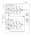
- FIG. 1 is a circuit diagram of the rotary electric machine device 100 according to the first embodiment.
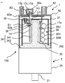
- FIG. 2 is a side sectional view of the rotary electric machine device 100 according to the first embodiment.
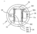
- FIG. 3 is a cross-sectional view of the upper surface of the rotary electric machine 100 according to the first embodiment.
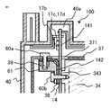
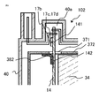
- FIG. 4 is an enlarged view of a lateral cross section of the rotary electric device 100 according to the first embodiment along the axis.
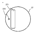
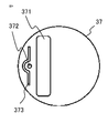
- FIG. 5 is a first top view of the electromagnetic shield 37 of the rotary electric machine 100 according to the first embodiment.
- FIG. 6 is a second top view of the electromagnetic shield 37 of the rotary electric machine 100 according to the first embodiment.
- FIG. 7 is a front view of the rotary electric machine device 100 according to the first embodiment.
- the control unit 1 and the rotary electric machine 2 are described in the circuit diagram of the rotary electric machine device 100 of FIG.
- the rotary electric machine device 100 may be a Y-connected or ⁇ -connected three-phase brushless rotary electric machine integrated with a control circuit, or may have a function of generating electricity by driving a load and using the regenerative power for battery charging. It may be.
- the rotary electric device 100 is used not only for the electric power steering device 150 but also for various purposes including for driving wheels of a vehicle.
- the control unit 1 is composed of an inverter circuit 3 for supplying a current to the rotary electric machine 2, a control circuit unit 4 equipped with a CPU (Central Processing Unit) 10, a power relay switching element 5, and a filter unit 17. There is.
- the filter unit 17 is provided to suppress noise caused by the inverter circuit 3.
- a power supply and a GND are connected to the filter unit 17 from the battery 6 mounted on the vehicle.
- the ignition switch 7 turns on the power to the power supply circuit 13 of the control circuit unit 4.
- the sensors 8 are connected to the input circuit 12 of the control circuit unit 4.
- the sensors are, for example, a steering angle sensor mounted near the steering wheel to detect the steering angle, a torque sensor to detect the steering torque, and a speed sensor to detect the traveling speed of the vehicle.
- the power supply that has passed through the filter unit 17 and the power supply relay switching element 5 by the signal from the power supply circuit 13 becomes the current source of the inverter circuit 3.
- the filter unit 17 is composed of a normal mode coil 17a, capacitors 17b, 17c, and 17d.
- a common mode coil may be added according to the noise generated by the rotary electric machine 100, the normal mode coil can be deleted, and the number of capacitors can be increased or decreased.
- the information from the sensors 8 is transmitted to the CPU 10 via the input circuit 12 of the control circuit unit 4.
- the CPU 10 calculates and outputs a control amount corresponding to a current for rotating the rotary electric machine 2 from the information.
- the output signal of the CPU 10 is transmitted to the inverter circuit 3 via the drive circuit 11 that constitutes the output circuit. Since the drive circuit 11 has only a small current flowing through it, it is arranged in the control circuit unit 4 and physically mounted on the control board 14 together with the CPU 10, the power supply circuit 13, and the input circuit 12. However, the drive circuit 11 can be arranged in the power module 35 together with the inverter circuit 3.
- the inverter circuit 3 mainly includes switching elements 31U, 31V, 31W for the upper arm for the three-phase windings U, V, W of the rotary electric machine 2, and switching elements 32U, 32V, 32W for the lower arm, and the rotary electric machine. It is provided with switching elements 34U, 34V, 34W for rotary electric relays that connect / disconnect wiring with windings. Further, the inverter circuit 3 includes shunt resistors 33U, 33V, 33W for current detection and smoothing capacitors 30U, 30V, 30W. It has the same circuit configuration for each phase winding, and current can be supplied to each phase winding independently.
- the potential difference between both ends of the shunt resistors 33U, 33V, and 33W, the winding terminal voltage of the rotary electric machine 2, and the like are also fed back to the input circuit 12. These pieces of information are also input to the CPU 10, and by calculating the difference from the detected value corresponding to the calculated current value and performing feedback control, a desired rotary electric current is supplied and the rotary electric machine is operated.
- the drive circuit 11 also outputs a drive signal of a power supply relay switching element 5 that operates as a relay that connects / disconnects the battery 6 and the power supply line of the inverter circuit 3.
- the switching element 5 also outputs the rotary electric machine 2 itself.
- the current supply to the inverter can be cut off.
- Switching elements 34U, 34V, and 34W for rotary electric relays are also arranged in the inverter circuit 3, and each phase can be cut off. Since a large current flows through the power supply relay switching element 5 and heat is generated, the power supply relay switching element 5 may be arranged in the power module 35 including the inverter circuit 3 instead of the control board 14.
- the CPU 10 has an abnormality detection function for detecting an abnormality in sensors 8, a drive circuit 11, an inverter circuit 3, a rotary electric winding, etc., and when an abnormality is detected, for example, only a predetermined phase is used according to the abnormality.
- the upper arm switching elements 31U, 31V, 31W, the lower arm switching elements 32U, 32V, 32W, or the rotary electric relay switching elements 34U, 34V, 34W are turned off. Further, in order to cut off the total current, it is also possible to turn off the power supply relay switching element 5 so as to cut off the power supply itself from the beginning.
- the rotary electric machine 2 is a brushless rotary electric machine in which the three-phase winding is ⁇ -connected. Since it is a brushless rotary electric machine, a rotation sensor 9 for detecting the rotation position of the rotor is mounted. The rotation information is also fed back to the input circuit 12. It should be noted that the brushless rotary electric machine having a three-phase delta connection may be used, and the rotary electric machine may have a Y connection or a two-pole, two-pair brushed rotary electric machine. Further, as the winding specifications, distributed winding or concentrated winding can be adopted as in the conventional device.
- Switching noise is generated by PWM (Pulse Width Modulation) control of the inverter circuit 3 of the control unit 1.
- a filter unit 17 is provided so that the switching noise is not transmitted to the outside from the rotary electric machine 100.
- the coil 17a is for normal mode noise and is called a normal mode coil. Further, although not shown, a coil called a common mode coil for common mode noise may be added.
- the capacitor 17b is also called an cross-the-line capacitor or an X capacitor.
- the capacitors 17c and 17d are called line bypass capacitors or Y capacitors. Conduction noise and radiation noise are suppressed by these filter elements, and they are called EMI (Electromagnetic Interface) filters.
- the midpoint 17e between the capacitors of the Y capacitors 17c and 17d is a body ground, and is electrically connected to the vehicle body via a part of the rotary electric machine 100 and grounded.
- FIG. 2 is a side sectional view for explaining the physical configuration of the rotary electric machine device 100 according to the first embodiment, and the control unit 1 is cut in a cross section including the axial center of the rotary electric machine 2.
- the rotary electric machine 2 is arranged on the lower side of FIG. 2, and the control unit 1 is arranged on the upper side, and both are adjacent to each other in the axial direction of the output shaft 21 of the rotary electric machine 2 and integrated.
- the rotary electric machine 2 is built in the rotary electric machine case 25 as in the conventional device, and has a rotor in which a plurality of permanent magnets (not shown) are arranged around the output shaft 21 and a winding having a gap in the rotor. A wound stator is placed. The windings are wound around each of the three phases, with the ends of each phase extending to the control unit 1 for connection (not shown).
- the upper part and the outer circumference of the control unit 1 are covered with a housing 40, and a power supply connector 42 through which a relatively large current of the power supply system flows and a signal connector 43 through which a relatively small current of the signal system flows are arranged on the upper part of the housing. ing.
- the power supply connector 42, the signal connector 43, and the housing 40 are integrally molded with a resin material.
- FIG. 3 is a cross-sectional view of the upper surface of the rotary electric machine 100 according to the first embodiment, and is a view of the lower surface cut under the ceiling surface of the electromagnetic shield 37 of the control unit 1 as viewed from the power connector side.
- a heat sink 34 is arranged in the central portion inside the housing 40.
- a pillar portion 341 formed in a columnar shape having a rectangular cross section is arranged in the center of the heat sink 34.
- the control board 14 is vertically arranged along one side surface of the pillar portion 341 of the heat sink 34 on the long side side.
- the bus bar unit 36 is arranged on the other side surface of the pillar portion 341 of the heat sink 34 on the long side side.
- the power module 35 is vertically arranged along one side surface on the short side side of the pillar portion 341 of the heat sink 34.
- the power module 35 has a terminal for connecting a control board on one side and a terminal for connecting a bus bar unit on the other side along the short side.
- the terminals for connecting the control board are connected by soldering, and the terminals for connecting the bus bar unit are connected by TIG (Tungsten Insert Gas) welding or the like.
- TIG Tusten Insert Gas
- the heat sink 34 is composed of the above-mentioned pillar portion 341 and an annular base portion 342 fixed to one end of the pillar portion 341 in the length direction.
- the pillar portion 341 of the heat sink 34 is arranged in the central portion of the housing 40 so that the length direction is along the axis of the housing 40 of the control unit 1.
- the outer peripheral surface of the base portion 342 of the heat sink 34 is inscribed in the inner peripheral surface of the rotary electric machine case 25 and is supported by the rotary electric machine case 25. That is, the heat sink 34 is arranged so that the base portion 342 is fixed to the rotary electric case 25 and the pillar portion 341 cantilevered and supported by the base portion 342 projects into the internal space of the housing 40.
- the base 342 of the heat sink 34 is provided with an insertion hole.
- the end of the three-phase winding of the rotary electric machine 2 is connected to the bus bar of the bus bar unit 36 of the control unit 1 through the insertion hole (not shown).
- the base 342 of the heat sink 34 has a stepped shape.
- the rotary electric machine case 25 is fixed to the outer peripheral portion of the large diameter portion of the base portion 342.
- a metal cylindrical electromagnetic shield 37 for suppressing noise emission is fixed to the outer peripheral portion of the base portion 342 having a small diameter.
- the electromagnetic shield 37 is arranged so as to cover the pillar portion 341 of the heat sink 34, the control board 14, the bus bar unit 36, and the power module 35. It protrudes into. In FIG. 2, only the control board 14 protrudes from the through hole 371 at the upper part of the electromagnetic shield. However, a part of the heat sink 34 and the bus bar unit 36 may protrude from the through hole 371.
- the bus bar unit 36 is composed of a bus bar holder 362 in which the bus bar 361 is embedded in a resin member, smoothing capacitors 30U, 30V, 30W, and a normal mode coil 17a.
- the bus bar 361 is the end of the three-phase winding of the rotary electric machine 2, the connection terminal of the power module 35, the terminals of the smoothing capacitors 30U, 30V, 30W and the normal mode coil 17a, the power supply extending from the power supply connector 42, and the GND. Connected to the terminal.
- the control board 14 mounts the control circuit unit 4 of FIG. 1, the power supply relay switching element 5, and the filter unit 17.
- the control board 14 is equipped with a circuit component for controlling an inverter circuit 3 for supplying an electric current to the rotary electric machine 2.
- An X capacitor 17b and Y capacitors 17c and 17d forming a filter are arranged in a protruding portion 141 protruding from a through hole 371 above the electromagnetic shield 37 of the control board 14. Further, the power supply extending from the power supply connector 42 and the external connection terminal of the ground are connected to the protruding portion 141 of the control board 14, and the filter unit 17 prevents noise from leaking to the outside through these connection terminals. I'm out.
- the X capacitor and the Y capacitor are arranged on the outer peripheral side of the protruding portion 141 in FIG. 2, they may be arranged on the inner peripheral side of the protruding portion 141.
- the normal mode coil 17a is arranged in the bus bar unit 36 in the above, it may be arranged in the protruding portion 141. Since it is not necessary to provide a substrate dedicated to the filter circuit or a circuit support structure dedicated to the filter circuit, the control unit can be configured in a compact size and at low cost. Then, these parts are housed and protected in the housing 40. By being housed in the housing 40, the parts can be prevented from being damaged, and the rotary electric device 100 can be easily handled.
- the capacitors 17b which are the X capacitors of the filter circuit
- the capacitors 17c, 17d which are the Y capacitors
- the control unit can be configured in a compact and low cost. Then, by providing the filter portion 17 having a noise removing ability on the outside of the through hole 371 of the electromagnetic shield 37, effective noise countermeasures can be implemented. Since the X capacitor and the Y capacitor of the filter circuit are grounded via the electromagnetic shield 37 instead of the heat sink whose path is close to that of the power module which is the noise source, noise can be suppressed.
- the protruding portion 141 is arranged in a concave portion inside the convex portion 40a provided on the upper portion of the housing 40, and suppresses the increase in size of the rotary electric device 100. That is, the ceiling surface of the control unit 1 can be kept compact except for the convex portions 40a, the power supply connector 42, and the signal connector 43 of the housing 40 of the control unit 1 of the rotary electric device 100, resulting in miniaturization. Has been successful.
- an L-shaped grounding bus bar 38 is arranged at a position on the outer peripheral side of the control board 14 and below the ceiling surface of the electromagnetic shield 37.
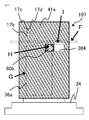
- FIG. 4 is an enlarged view of a lateral cross section of the rotary electric device 100 according to the first embodiment, showing the connection between the control board 14 and the electromagnetic shield 37.
- the grounding bus bar 38 has an L shape, and its horizontal surface is in contact with the inside of the upper surface of the electromagnetic shield 37 and is electrically connected.
- the vertical surface is in contact with the GND pattern 142 of the control board 14 and is electrically connected.
- a hexagon nut 39 is arranged at the lower part of the grounding bus bar 38 in contact with the electromagnetic shield 37 and is supported by the resin holder 61.
- the screw 60a is screwed from above the upper surface of the electromagnetic shield 37, and the grounding bus bar 38 and the lower surface of the electromagnetic shield 37 are brought into close contact with each other to be electrically connected.
- the hexagon nut 39 is held by a resin holder 61 arranged under the grounding bus bar 38 and is prevented from rotating.
- the resin holder 61 holding the hexagon nut 39 is assembled to the grounding bus bar 38 by press fitting or the like.
- the electromagnetic shield 37, the grounding bus bar 38, and the hexagon nut 39 are assembled in this order from the top surface, and the screw 60a is tightened from the top surface.
- an obstructive structure does not protrude into the space above the screw 60a. It is not necessary to secure a distance from the electromagnetic shield 37 of the control unit 1 to the housing 40, which contributes to the miniaturization of the control unit 1 in the axial direction.
- the vertical surface of the grounding bus bar 38 is electrically connected to the GND pattern 142 on the side of the control board 14.
- the GND pattern 142 constitutes the filter unit 17 together with the X capacitors 17b, the Y capacitors 17c, and 17d arranged on the control board.
- the surface of the grounding bus bar 38 in contact with the control board 14 is screwed from the outer peripheral side by screws 60b.
- the vertical portion of the resin holder 61, the vertical portion of the grounding bus bar 38, and the control board 14 are fixed to the screw tightening base 343 of the heat sink 34 by the screws 60b.
- the grounding bus bar 38 and the GND pattern 142 of the filter unit 17 are electrically connected by tightening the screw 60b. Since the filter unit 17 is configured by the GND pattern 142, highly reliable and low-cost connection is possible.
- the screw 60b is electrically connected to the heat sink 34 by screw tightening.
- the resin holder 61 and the heat sink 34 side of the control board 14 are both insulated, the electromagnetic shield 37 and the GND pattern 142 of the control board 14 are electrically connected to the screw 60b and the heat sink 34.
- the X capacitors 17b, Y capacitors 17c, and 17d of the filter circuit are arranged on the upper part of the control board 14, it is not necessary to provide a board dedicated to the filter circuit, or it is not necessary to provide a circuit support structure dedicated to the filter circuit. Therefore, the control unit can be miniaturized and constructed at low cost. Further, since the X capacitor and the Y capacitor of the filter circuit are grounded via the electromagnetic shield 37 instead of the heat sink whose path is close to that of the power module which is the noise source, noise can be suppressed.
- the structure is such that the screw 60b is used to tighten from the outer peripheral side of the central shaft of the rotary electric machine, and the vertical surface of the grounding bus bar 38 is arranged on the outer peripheral side of the control board 14.
- the component for connecting the electromagnetic shield 37 and the grounding bus bar 38 protrudes from the upper surface of the heat sink 34, and space is not wasted, which contributes to the miniaturization of the control unit 1.
- FIG. 5 shows a first top view of the electromagnetic shield 37 of the rotary electric machine 100 according to the first embodiment.
- a through hole 371 for projecting the control board 14 and a screw insertion hole 372 for passing the screw 60a are provided on the upper surface of the electromagnetic shield 37.
- FIG. 6 shows a second top view of the electromagnetic shield 37 of the rotary electric machine 100 according to the first embodiment.
- a notch hole 373 for facilitating the deformation of the electromagnetic shield 37 is provided around the screw insertion hole 372.
- various shapes can be considered including the variations shown in FIGS. 5 and 6.
- the through hole 371 may be enlarged so that a part of the upper part of the heat sink 34 or the bus bar unit 36 protrudes from the electromagnetic shield 37.
- FIG. 7 is a front view of the rotary electric machine 100 according to the first embodiment.
- FIG. 7 is a front view of the control board 14 with the housing 40 of the control unit and the electromagnetic shield 37 removed.
- a grounding bus bar 38 that connects the control board 14 and the electromagnetic shield 37 is arranged in the center of the control board 14.
- the portion of the alternate long and short dash line indicated by the arrow A in FIG. 7 indicates the position of the ceiling surface of the electromagnetic shield 37.
- the arrow B indicates the position where the screw 60b of the control board 14 is screwed.
- the arrow C indicates the position where the grounding bus bar 38 and the electromagnetic shield 37 are connected by the screw 60a.
- both the screws 60a and 60b can fix the control board 14 and the electromagnetic shield 37 at the center in the horizontal direction in FIG. 7, which is advantageous in terms of vibration resistance and durability.
- the screw 60a is arranged perpendicular to the top surface of the electromagnetic shield 37.
- the screws 60b are arranged perpendicular to the control board 14.
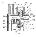
- FIG. 8 is an enlarged view of a lateral cross section of the rotary electric device 101 according to the second embodiment along the axis.
- FIG. 4 The difference from FIG. 4 according to the first embodiment is that the hexagon nut 39 was abolished for fixing the screw 60a, and the grounding bus bar 381 was burred and threaded to form the female screw portion 381a. It is a point.
- a female thread portion 381a is provided on the grounding bus bar 381, and the electromagnetic shield 37 and the grounding bus bar 381 are connected by the screw 60a.
- a resin holder 611 in which the tip of the screw 60a is housed is arranged under the grounding bus bar 381. Similar to the first embodiment, the resin holder 611 is also extended to the tightening side of the screw 60b between the grounding bus bar 381 and the control board 14. The screw 60b is used as an insulating material when the grounding bus bar 381 and the control board 14 are screwed to the heat sink 34. The resin holder 611 is assembled to the grounding bus bar 381 by press fitting or the like.
- the electromagnetic shield 37 can be electrically connected to the grounding bus bar 381 without using the hexagon nut 39, and can be configured at a lower cost.
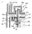
- FIG. 9 is an enlarged view of a lateral cross section of the rotary electric device 102 according to the third embodiment along the axis.
- grounding bus bar 38 fixed by the screws 60a and 60b
- a grounding bus bar 382 that maintains an electrical connection by soldering and pressing contact is provided. be.
- the grounding bus bar 382 is surface-mounted on the GND pattern 142 connected to the filter unit 17 on the control board 14 by reflow soldering.
- the electrical connection with the electromagnetic shield 372 is such that when the control board 14 is assembled to the heat sink 34, the inside of the upper surface of the electromagnetic shield 372 comes into contact with the grounding bus bar 382 in a bent state. By doing so, the screws 60a and 60b and the resin holder 61 can be deleted, and the number of parts can be reduced. Therefore, it can contribute to cost reduction.
- a leaf spring-like elastic member that can be mounted on the control board 14 can be used for the grounding bus bar 382.
- the leaf spring-like elastic member it is possible to make the electrical connection with the electromagnetic shield 372 more secure by utilizing the deflection and the repulsive force.
- FIG. 10 is a front view of the rotary electric device 103 according to the fourth embodiment.
- FIG. 10 is a front view of the control board 143 with the housing 40 of the control unit and the electromagnetic shield 37 removed.
- a grounding bus bar 383 that connects the control board 143 and the electromagnetic shield 37 is arranged near the center of the control board 143.
- the portion of the alternate long and short dash line indicated by the arrow A in FIG. 10 indicates the position of the ceiling surface of the electromagnetic shield 37.
- the arrow B indicates the position where the screw 60b is screwed into the control board 143.
- the arrow C indicates the position where the grounding bus bar 383 and the electromagnetic shield 37 are connected by the screw 60a.
- the axis of the screw 60a is arranged on the first plane parallel to the axis of the rotary electric machine 2, and the axis of the screw 60b is arranged on the second plane parallel to the first plane.
- the control board 14 and the electromagnetic shield 37 can be fixed together with the screws 60a and 60b.
- FIG. 11 is an enlarged view of a lateral cross section of the rotary electric device 104 along the axis according to the fifth embodiment.
- FIG. 11 is different from FIG. 4 according to the first embodiment in that the coil 17a is provided on the protruding portion 141 of the control board 14.
- the coil 17a constitutes the filter unit 17 together with the X capacitors 17b, the Y capacitors 17c, and 17d arranged on the control board.
- the noise can be reduced by the filter unit 17 after the noise is absorbed by the electromagnetic shield 37.
- FIG. 12 is an enlarged view of a lateral cross section of the rotary electric device 105 according to the sixth embodiment along the axis.
- a part or all of the X capacitors 17b, the Y capacitors 17c, and 17d mounted on the protruding portion 141 of the control board 14 are through holes of the electromagnetic shield 37. It is provided at a position where the side surface of the capacitor contacts the outer surface of the 371.
- FIG. 13 is an enlarged view of a lateral cross section of the rotary electric device 106 according to the seventh embodiment along the axis.
- FIG. 13 shows that, with respect to FIG. 12 according to the sixth embodiment, a part or all of the X capacitors 17b, Y capacitors 17c, and 17d mounted on the protruding portion 141 of the control board 14 are through holes of the electromagnetic shield 37. The difference is that it is placed so as to straddle the outer surface of the 371.
- the capacitor which is a component of the filter unit 17, in this way, it is significant because the noise can be reduced by the filter unit immediately after the noise is absorbed by the electromagnetic shield 37.
- FIG. 14 is a circuit diagram of the rotary electric machine device 107 according to the eighth embodiment.
- FIG. 15 is a side sectional view of the rotary electric device 107 according to the eighth embodiment.
- FIG. 16 is a first front view of the rotary electric device 107 according to the eighth embodiment.
- FIG. 17 is a second front view of the rotary electric device 107 according to the eighth embodiment.
- the rotary electric device 107 according to the eighth embodiment has a configuration in which a control circuit, a connector, a sensor, and the like all have two independent control systems, and is configured to ensure redundancy.
- FIG. 14 is a diagram showing two common electric circuits according to the eighth embodiment. It is an electric system having two electric systems described with reference to FIG. 1 of the first embodiment.
- the housing 400 covers the upper portion and the outer circumference of the control unit 111.
- Power supply connectors 42a and 42b through which a large current flows and signal connectors 43a and 43b through which a small current flows are arranged above the housing 400.
- the power supply connectors 42a and 42b, the signal connectors 43a and 43b, and the housing 400 are integrally molded with a resin material.
- a heat sink 345 is arranged in the central portion of the inside of the housing 400 of the control unit 111.
- a pillar portion 346 having a rectangular cross section is arranged in the center of the heat sink 345.
- the control board 41a is vertically arranged on one side surface on the long side side of the cross section of the pillar portion 346 of the heat sink 345.
- the control board 41b is arranged so that the cross section of the pillar portion 346 of the heat sink 345 is vertically arranged on the other side surface on the long side.
- the bus bar unit 36a is arranged on the outer peripheral side of the control board 41a.
- the bus bar unit 36b is arranged on the outer peripheral side of the control board 41b.
- the power module 35a is vertically arranged along the short side of the cross section of the pillar portion 346 of the heat sink 345 at the position of the alternate long and short dash line indicated by the arrow E, and the power module 35b is vertically arranged along the other side surface.
- the power modules 35a and 35b have terminals for connecting the control board on one side in the short side direction of the cross section of the pillar portion 346 of the heat sink 345, and terminals for connecting the bus bar unit on the other side, and are for connecting the control board.
- the terminals are connected by soldering, and the terminals for connecting the bus bar unit are connected by TIG welding or the like.
- the base 342 of the heat sink 345 is provided with the electromagnetic shield 375 as in the first embodiment, and the upper portions of the control boards 41a and 41b project from the electromagnetic shield 375 through the through holes 374 provided in the upper portion of the electromagnetic shield. Parts 41c and 41d are formed. X capacitors 17b and Y capacitors 17c and 17d are arranged on the protrusions 41c and 41d, respectively.
- a grounding bus bar 38, a resin holder 61, a hexagon nut 39, a screw 60a, and a screw 60b are provided on the outer peripheral sides of the control boards 41a and 41b, respectively, and are connected to the electromagnetic shield 375 by screw tightening.
- the GND pattern (not shown) of each of the filter units 17 of 41b is connected to the electromagnetic shield 375.
- the connection method is the same as that of the first embodiment, but the connection method may be the same as that of the second and third embodiments.
- FIG. 16 is a first front view of the rotary electric device 106 according to the eighth embodiment.
- FIG. 17 is a second front view of the rotary electric device 106 according to the eighth embodiment, and is a modified example of FIG.
- the alternate long and short dash line indicated by the arrow F is the position of the upper surface of the electromagnetic shield 375.
- the portion surrounded by the alternate long and short dash line of the arrow G is a diagram showing the position of the bus bar unit 36a. As shown in FIGS. 15, 16 and 17, the bus bar unit 36a is arranged at a distance from the screw tightening portion on the control board 41a side indicated by the arrow H of the grounding bus bar 38 or 384.
- the screw tightening portion on the control board 41a side indicated by the arrow H and the screw tightening portion on the electromagnetic shield 37 side indicated by the arrow I are horizontal of the control boards 41a and 41b in FIG. 16 as in the first embodiment. It may be in the center position of the direction. Further, as shown in FIG. 17, the configuration may be shifted in the horizontal direction of FIG. Further, the bus bar unit 36b on the control board 41b side can be arranged in the same manner. Arrows G in FIGS.
- connection structure of the grounding bus bars 38 and 384 can be arranged so as to avoid interfering with the bus bar units 36a and 36b, which contributes to miniaturization and cost reduction of the rotary electric device 106. doing.
- FIG. 18 is a configuration diagram of the electric power steering device 150 according to the ninth embodiment. An example in which the rotary electric machine 100 is applied to the electric power steering device 150 mounted on the vehicle will be described.
- FIG. 18 is an overall configuration diagram of the electric power steering device 150, which is an example of the rack type electric power steering device 150.
- the torque sensor 152 detects the steering torque and outputs it to the rotary electric appliance 100.
- the speed sensor 153 detects the traveling speed of the vehicle and outputs it to the rotary electric machine device 100.
- the rotary electric device 100 generates an auxiliary torque that assists the steering torque based on the inputs from the torque sensor 152 and the speed sensor 153, and supplies the auxiliary torque to the steering mechanism of the front wheel 154 of the vehicle.
- the torque sensor 152 and the speed sensor 153 are a part of the sensors 8 in FIG.
- the rotary electric device 100 may generate an auxiliary torque based on an input other than the torque sensor 152 and the speed sensor 153.
- the mountability on the vehicle is improved.
- the cost of the rotary electric device 100 By downsizing the rotary electric device 100 applied to the electric power steering device 150, the mountability on the vehicle is improved.
- the cost of the electric power steering device 150 By reducing the cost of the rotary electric device 100, the cost of the electric power steering device 150 as a whole can be reduced.
- the rotary electric machine devices 101 to 107 are used instead of the rotary electric machine device 100.
Landscapes
- Engineering & Computer Science (AREA)
- Power Engineering (AREA)
- Chemical & Material Sciences (AREA)
- Combustion & Propulsion (AREA)
- Transportation (AREA)
- Mechanical Engineering (AREA)
- Microelectronics & Electronic Packaging (AREA)
- Physics & Mathematics (AREA)
- Electromagnetism (AREA)
- Power Steering Mechanism (AREA)
Abstract
Description
回転軸を有する回転電機と、
回転電機に対して回転軸の軸方向の一方側に配置され、回転電機を制御する制御ユニットと、
制御ユニットに設けられ、回転軸の軸方向の一方側へ伸びる突出部を有する制御基板と、
制御ユニットを包囲し、制御基板の突出部が貫通する貫通孔が設けられた電磁シールドと、
電磁シールドの外側に配置され、制御基板の突出部に取り付けられた外部接続端子と、
電磁シールドの外側に配置されて、制御基板の突出部に取り付けられ、外部接続端子へ伝搬するノイズ成分を減衰させるフィルタとを備えたものである。
実施の形態1について説明する。図1は、実施の形態1における回転電機装置100の回路図である。図2は、実施の形態1における回転電機装置100の側方の断面図である。図3は、実施の形態1に係る回転電機装置100の上面の断面図である。図4は、実施の形態1に係る回転電機装置100の軸心に沿った側方の断面の拡大図である。図5は、実施の形態1に係る回転電機装置100の電磁シールド37の第一の上面図である。図6は、実施の形態1に係る回転電機装置100の電磁シールド37の第二の上面図である。図7は、実施の形態1に係る回転電機装置100の正面図である。
図1の回転電機装置100の回路図には、制御ユニット1と回転電機2が記載されている。回転電機装置100は、Y結線またはΔ結線の三相ブラシレス回転電機の制御回路一体型のものであってもよいし、負荷の駆動により発電して回生電力をバッテリ充電に利用する機能を有するものであってもよい。回転電機装置100は、電動パワーステアリング装置150だけでなく、車両の車輪駆動用を含めて様々な用途に用いられる。
図2は、実施の形態1に係る回転電機装置100の物理的構成を説明するための側方の断面図であり、制御ユニット1が回転電機2の軸心を含む断面で切断されている。図2の下側に回転電機2が配置され、上側に制御ユニット1が配置され、両者は回転電機2の出力軸21の軸方向に隣接し一体化されている。回転電機2は、従来装置と同様に回転電機ケース25に内蔵され、出力軸21の周囲には図示しない永久磁石が複数極対配置されたロータ及び、このロータに隙間を有して巻線が巻装されたステータが配置されている。巻線は三相それぞれに巻装されており、各相の端部は、接続のために制御ユニット1へ伸びている(不図示)。
制御基板14は、図1の制御回路部4、電源リレー用スイッチング素子5、フィルタ部17を実装している。制御基板14は、回転電機2へ電流を供給するためのインバータ回路3を制御するための回路部品を搭載している。制御基板14の電磁シールド37の上部の貫通孔371から突出した突出部141にはフィルタを構成するXコンデンサ17bと、Yコンデンサ17c、17dが配置されている。また、制御基板14の突出部141には、電源用コネクタ42から伸びた電源とグランドの外部接続端子が接続されており、これらの接続端子を通してノイズが外部へ漏出するのをフィルタ部17が防いでいる。なお図2ではXコンデンサ、Yコンデンサは突出部141の外周側に配置しているが、突出部141の内周側に配置してもよい。またノーマルモードコイル17aは上記ではバスバーユニット36に配置したが、突出部141に配置してもよい。フィルタ回路専用の基板を設ける必要がなく、もしくはフィルタ回路専用の回路支持構造を設ける必要がないため、小型化かつ低コストに制御ユニットを構成することができる。そして、これらの部品は、ハウジング40に収納され保護される。ハウジング40に収納されることで、部品が破損を免れることができ、回転電機装置100として取り扱いが容易となる。
また制御基板14の外周側の面と、電磁シールド37の天井面の下側の位置にL字形状の接地用バスバー38が配置されている。
図5に、実施の形態1に係る回転電機装置100の電磁シールド37の第一の上面図を示す。電磁シールド37の上面には制御基板14を突出させるための貫通孔371と、ねじ60aを通すためのねじ挿通穴372が設けられている。
図8は、実施の形態2に係る回転電機装置101の軸心に沿った側方の断面の拡大図である。
図9は、実施の形態3に係る回転電機装置102の軸心に沿った側方の断面の拡大図である。
図10は、実施の形態4に係る回転電機装置103の正面図である。
図11は、実施の形態5に係る、回転電機装置104の軸心に沿った側方の断面の拡大図である。
図12は、実施の形態6に係る回転電機装置105の軸心に沿った側方の断面の拡大図である。
図13は実施の形態7に係る回転電機装置106の軸心に沿った側方の断面の拡大図である。
図14は実施の形態8に係る回転電機装置107の回路図である。図15は実施の形態8に係る回転電機装置107の側方の断面図である。図16は実施の形態8に係る回転電機装置107の第一の正面図である。図17は、実施の形態8に係る回転電機装置107の第二の正面図である。
図18は、実施の形態9に係る電動パワーステアリング装置150の構成図である。回転電機装置100を車両に搭載される電動パワーステアリング装置150に適用した例について説明する。
Claims (20)
- 回転軸を有する回転電機と、
前記回転電機に対して前記回転軸の軸方向の一方側に配置され、前記回転電機を制御する制御ユニットと、
前記制御ユニットに設けられ、前記回転軸の前記軸方向の一方側へ伸びる突出部を有する制御基板と、
前記制御ユニットを包囲し、前記制御基板の前記突出部が貫通する貫通孔が設けられた電磁シールドと、
前記電磁シールドの外側に配置され、前記制御基板の前記突出部に取り付けられた外部接続端子と、
前記電磁シールドの外側に配置されて、前記制御基板の前記突出部に取り付けられ、前記外部接続端子へ伝搬するノイズ成分を減衰させるフィルタとを備えた回転電機装置。 - 前記制御基板は、前記フィルタと前記外部接続端子に接続する配線パターンを有し、
前記制御基板の前記配線パターンと、前記電磁シールドとに電気的に接続された、接地用バスバーを備えた請求項1に記載の回転電機装置。 - 第一のねじと、ヒートシンクと、樹脂部材とを備え、
前記ヒートシンクに、前記制御基板と、前記接地用バスバーと、前記樹脂部材とが第一のねじでねじ止めされ、
前記制御基板の前記配線パターンと前記接地用バスバーとが電気的に接続された請求項2に記載の回転電機装置。 - 前記回転電機の軸心側に前記ヒートシンクが配置され、前記ヒートシンクの外周側に前記制御基板が配置され、前記制御基板の外周側に前記接地用バスバーが設置され、最外周側に前記樹脂部材が配置された請求項3に記載の回転電機装置。
- 第二のねじを備え、
前記接地用バスバーに、前記電磁シールドが前記第二のねじでねじ止めされ、
前記接地用バスバーと前記電磁シールドとが電気的に接続された請求項2から4のいずれか一項に記載の回転電機装置。 - 第二のねじと、ナットとを備え、
前記接地用バスバーと、前記電磁シールドとが、前記ナットと前記第二のねじでねじ止めされ、
前記接地用バスバーと前記電磁シールドとが電気的に接続された請求項2から4のいずれか一項に記載の回転電機装置。 - 前記接地用バスバーに対して、前記軸方向の一方側に、前記電磁シールドが配置された請求項5または6に記載の回転電機装置。
- 前記制御基板の前記配線パターンと半田で固定され、前記電磁シールドに圧着されて、前記制御基板の前記配線パターンと前記電磁シールドとに電気的に接続された前記接地用バスバーを備えた請求項2に記載の回転電機装置。
- 前記接地用バスバーは板バネ状の弾力性部材である、請求項8に記載の回転電機装置。
- 第一のねじと、
第二のねじと、
前記制御基板に前記第一のねじで取り付けられ、前記電磁シールドに前記第二のねじで取り付けられた接地用バスバーとを備え、
前記第一のねじの軸心と前記第二のねじの軸心は前記回転電機の軸心を包含する同一平面上に配置された請求項1から7のいずれか一項に記載の回転電機装置。 - 第一のねじと、
第二のねじと、
前記制御基板と前記第一のねじで取付けられ、前記電磁シールドと前記第二のねじで取り付けられた接地用バスバーとを備え、
前記回転電機の軸心に平行な第一の平面の上に前記第一のねじの軸心が配置され、第一の平面に平行な第二の平面の上に前記第二のねじの軸心が配置された請求項1から7のいずれか一項に記載の回転電機装置。 - 前記第一のねじの軸心は前記制御基板に垂直に、前記第二のねじの軸心は前記電磁シールドに垂直に配置された、請求項10または11に記載の回転電機装置。
- 前記制御基板と前記接地用バスバーとの取付け部から間隔を設け、前記制御基板に平行に配置された、大型部品を搭載したバスバーを備えた請求項2から12のいずれか一項に記載の回転電機装置。
- 前記制御基板の前記突出部と、前記突出部に接続された前記外部接続端子とを収納し、前記電磁シールドの外を覆って内部の部品を保護するハウジングを備えた請求項1から13のいずれか一項に記載の回転電機装置。
- 前記ハウジングは凸部を有し、前記制御基板の前記突出部が、前記ハウジングの凸部の内側に収納された請求項14に記載の回転電機装置。
- 前記制御基板の前記突出部に取り付けられた、前記フィルタがコンデンサである請求項1から15のいずれか一項に記載の回転電機装置。
- 前記制御基板の前記突出部に取り付けられた、前記フィルタがコンデンサとコイルである請求項1から15のいずれか一項に記載の回転電機装置。
- 前記コンデンサは、前記コンデンサの側面が、前記制御基板の前記突出部の、前記電磁シールドに設けられた前記貫通孔の外側の面に接する位置に設けられた請求項16または17に記載の回転電機装置。
- 前記コンデンサは、前記制御基板の前記突出部の、前記電磁シールドに設けられた前記貫通孔の外側の面をまたぐ位置に設けられた請求項16または17に記載の回転電機装置。
- 請求項1から19のいずれか一項に記載の回転電機装置を備えた電動パワーステアリング装置。
Priority Applications (5)
| Application Number | Priority Date | Filing Date | Title |
|---|---|---|---|
| EP20926914.1A EP4131736A4 (en) | 2020-03-27 | 2020-03-27 | ELECTRIC ROTARY MACHINE DEVICE AND ELECTRIC POWER STEERING DEVICE |
| CN202080098089.3A CN115280644A (zh) | 2020-03-27 | 2020-03-27 | 旋转电机装置及电动助力转向装置 |
| JP2022510307A JP7321361B2 (ja) | 2020-03-27 | 2020-03-27 | 回転電機装置および電動パワーステアリング装置 |
| PCT/JP2020/013925 WO2021192202A1 (ja) | 2020-03-27 | 2020-03-27 | 回転電機装置および電動パワーステアリング装置 |
| US17/796,816 US20230049080A1 (en) | 2020-03-27 | 2020-03-27 | Electric rotating machine apparatus and electric power steering apparatus |
Applications Claiming Priority (1)
| Application Number | Priority Date | Filing Date | Title |
|---|---|---|---|
| PCT/JP2020/013925 WO2021192202A1 (ja) | 2020-03-27 | 2020-03-27 | 回転電機装置および電動パワーステアリング装置 |
Publications (1)
| Publication Number | Publication Date |
|---|---|
| WO2021192202A1 true WO2021192202A1 (ja) | 2021-09-30 |
Family
ID=77891131
Family Applications (1)
| Application Number | Title | Priority Date | Filing Date |
|---|---|---|---|
| PCT/JP2020/013925 WO2021192202A1 (ja) | 2020-03-27 | 2020-03-27 | 回転電機装置および電動パワーステアリング装置 |
Country Status (5)
| Country | Link |
|---|---|
| US (1) | US20230049080A1 (ja) |
| EP (1) | EP4131736A4 (ja) |
| JP (1) | JP7321361B2 (ja) |
| CN (1) | CN115280644A (ja) |
| WO (1) | WO2021192202A1 (ja) |
Citations (3)
| Publication number | Priority date | Publication date | Assignee | Title |
|---|---|---|---|---|
| JPH038555B2 (ja) | 1982-08-03 | 1991-02-06 | Yamaha Corp | |
| WO2017175325A1 (ja) * | 2016-04-06 | 2017-10-12 | 三菱電機株式会社 | 電動パワーステアリング装置 |
| WO2018047342A1 (ja) | 2016-09-12 | 2018-03-15 | 三菱電機株式会社 | モータ制御装置及び電動パワーステアリング制御装置 |
Family Cites Families (3)
| Publication number | Priority date | Publication date | Assignee | Title |
|---|---|---|---|---|
| DE102013001339A1 (de) * | 2013-01-26 | 2014-07-31 | Brose Fahrzeugteile GmbH & Co. Kommanditgesellschaft, Würzburg | Rotierende elektrische Maschine |
| JP6256382B2 (ja) * | 2015-02-27 | 2018-01-10 | 株式会社豊田自動織機 | 電動圧縮機 |
| JP6608555B1 (ja) * | 2019-05-17 | 2019-11-20 | 三菱電機株式会社 | 駆動装置、および電動パワーステアリング装置 |
-
2020
- 2020-03-27 US US17/796,816 patent/US20230049080A1/en active Pending
- 2020-03-27 WO PCT/JP2020/013925 patent/WO2021192202A1/ja active Application Filing
- 2020-03-27 CN CN202080098089.3A patent/CN115280644A/zh active Pending
- 2020-03-27 JP JP2022510307A patent/JP7321361B2/ja active Active
- 2020-03-27 EP EP20926914.1A patent/EP4131736A4/en active Pending
Patent Citations (3)
| Publication number | Priority date | Publication date | Assignee | Title |
|---|---|---|---|---|
| JPH038555B2 (ja) | 1982-08-03 | 1991-02-06 | Yamaha Corp | |
| WO2017175325A1 (ja) * | 2016-04-06 | 2017-10-12 | 三菱電機株式会社 | 電動パワーステアリング装置 |
| WO2018047342A1 (ja) | 2016-09-12 | 2018-03-15 | 三菱電機株式会社 | モータ制御装置及び電動パワーステアリング制御装置 |
Non-Patent Citations (1)
| Title |
|---|
| See also references of EP4131736A4 |
Also Published As
| Publication number | Publication date |
|---|---|
| JP7321361B2 (ja) | 2023-08-04 |
| US20230049080A1 (en) | 2023-02-16 |
| EP4131736A4 (en) | 2023-05-10 |
| EP4131736A1 (en) | 2023-02-08 |
| JPWO2021192202A1 (ja) | 2021-09-30 |
| CN115280644A (zh) | 2022-11-01 |
Similar Documents
| Publication | Publication Date | Title |
|---|---|---|
| WO2018047342A1 (ja) | モータ制御装置及び電動パワーステアリング制御装置 | |
| CN109070933B (zh) | 电动助力转向装置 | |
| WO2016163037A1 (ja) | 電動パワーステアリング装置 | |
| JP7067339B2 (ja) | 駆動装置、および、これを用いた電動パワーステアリング装置 | |
| US20090267430A1 (en) | Electric power steering apparatus | |
| CN108778897B (zh) | 电动助力转向装置 | |
| WO2015198476A1 (ja) | 一体型電動パワーステアリング装置、及びその製造方法 | |
| US10800444B2 (en) | Electric driving device and electric power steering device | |
| US11932324B2 (en) | Electric drive device of electric power steering apparatus | |
| CN111971880B (zh) | 电动助力转向装置 | |
| US11956900B2 (en) | Electronic control unit and method for assembling electronic control unit | |
| WO2021192202A1 (ja) | 回転電機装置および電動パワーステアリング装置 | |
| JP2021127016A (ja) | 駆動装置 | |
| JP4952666B2 (ja) | 電動式パワーステアリング装置 | |
| JP7357802B2 (ja) | 回転電機装置および電動パワーステアリング装置 | |
| JP4931498B2 (ja) | モータ装置 | |
| JP2008290675A (ja) | 電動パワーステアリング装置 | |
| JP7361789B2 (ja) | 回転電機装置および電動パワーステアリング装置 | |
| WO2023095218A1 (ja) | モータ装置およびモータ制御装置 |
Legal Events
| Date | Code | Title | Description |
|---|---|---|---|
| 121 | Ep: the epo has been informed by wipo that ep was designated in this application |
Ref document number: 20926914 Country of ref document: EP Kind code of ref document: A1 |
|
| ENP | Entry into the national phase |
Ref document number: 2022510307 Country of ref document: JP Kind code of ref document: A |
|
| WWE | Wipo information: entry into national phase |
Ref document number: 2020926914 Country of ref document: EP |
|
| ENP | Entry into the national phase |
Ref document number: 2020926914 Country of ref document: EP Effective date: 20221027 |
|
| NENP | Non-entry into the national phase |
Ref country code: DE |