WO2017154838A1 - モータ及びモータの製造方法 - Google Patents
モータ及びモータの製造方法 Download PDFInfo
- Publication number
- WO2017154838A1 WO2017154838A1 PCT/JP2017/008792 JP2017008792W WO2017154838A1 WO 2017154838 A1 WO2017154838 A1 WO 2017154838A1 JP 2017008792 W JP2017008792 W JP 2017008792W WO 2017154838 A1 WO2017154838 A1 WO 2017154838A1
- Authority
- WO
- WIPO (PCT)
- Prior art keywords
- winding
- center piece
- stator
- rotor
- extending portion
- Prior art date
- Legal status (The legal status is an assumption and is not a legal conclusion. Google has not performed a legal analysis and makes no representation as to the accuracy of the status listed.)
- Ceased
Links
Images







Classifications
-
- H—ELECTRICITY
- H02—GENERATION; CONVERSION OR DISTRIBUTION OF ELECTRIC POWER
- H02K—DYNAMO-ELECTRIC MACHINES
- H02K11/00—Structural association of dynamo-electric machines with electric components or with devices for shielding, monitoring or protection
- H02K11/30—Structural association with control circuits or drive circuits
-
- H—ELECTRICITY
- H02—GENERATION; CONVERSION OR DISTRIBUTION OF ELECTRIC POWER
- H02K—DYNAMO-ELECTRIC MACHINES
- H02K3/00—Details of windings
- H02K3/32—Windings characterised by the shape, form or construction of the insulation
- H02K3/38—Windings characterised by the shape, form or construction of the insulation around winding heads, equalising connectors, or connections thereto
-
- H—ELECTRICITY
- H02—GENERATION; CONVERSION OR DISTRIBUTION OF ELECTRIC POWER
- H02K—DYNAMO-ELECTRIC MACHINES
- H02K1/00—Details of the magnetic circuit
- H02K1/06—Details of the magnetic circuit characterised by the shape, form or construction
- H02K1/12—Stationary parts of the magnetic circuit
- H02K1/14—Stator cores with salient poles
- H02K1/146—Stator cores with salient poles consisting of a generally annular yoke with salient poles
-
- H—ELECTRICITY
- H02—GENERATION; CONVERSION OR DISTRIBUTION OF ELECTRIC POWER
- H02K—DYNAMO-ELECTRIC MACHINES
- H02K1/00—Details of the magnetic circuit
- H02K1/06—Details of the magnetic circuit characterised by the shape, form or construction
- H02K1/22—Rotating parts of the magnetic circuit
- H02K1/27—Rotor cores with permanent magnets
- H02K1/2786—Outer rotors
- H02K1/2787—Outer rotors the magnetisation axis of the magnets being perpendicular to the rotor axis
- H02K1/2788—Outer rotors the magnetisation axis of the magnets being perpendicular to the rotor axis the rotor consisting of a single magnet or two or more axially juxtaposed single magnets
-
- H—ELECTRICITY
- H02—GENERATION; CONVERSION OR DISTRIBUTION OF ELECTRIC POWER
- H02K—DYNAMO-ELECTRIC MACHINES
- H02K11/00—Structural association of dynamo-electric machines with electric components or with devices for shielding, monitoring or protection
- H02K11/04—Structural association of dynamo-electric machines with electric components or with devices for shielding, monitoring or protection for rectification
- H02K11/049—Rectifiers associated with stationary parts, e.g. stator cores
- H02K11/05—Rectifiers associated with casings, enclosures or brackets
-
- H—ELECTRICITY
- H02—GENERATION; CONVERSION OR DISTRIBUTION OF ELECTRIC POWER
- H02K—DYNAMO-ELECTRIC MACHINES
- H02K11/00—Structural association of dynamo-electric machines with electric components or with devices for shielding, monitoring or protection
- H02K11/30—Structural association with control circuits or drive circuits
- H02K11/33—Drive circuits, e.g. power electronics
-
- H—ELECTRICITY
- H02—GENERATION; CONVERSION OR DISTRIBUTION OF ELECTRIC POWER
- H02K—DYNAMO-ELECTRIC MACHINES
- H02K15/00—Processes or apparatus specially adapted for manufacturing, assembling, maintaining or repairing of dynamo-electric machines
- H02K15/02—Processes or apparatus specially adapted for manufacturing, assembling, maintaining or repairing of dynamo-electric machines of stator or rotor bodies
- H02K15/021—Magnetic cores
- H02K15/022—Magnetic cores with salient poles
-
- H—ELECTRICITY
- H02—GENERATION; CONVERSION OR DISTRIBUTION OF ELECTRIC POWER
- H02K—DYNAMO-ELECTRIC MACHINES
- H02K15/00—Processes or apparatus specially adapted for manufacturing, assembling, maintaining or repairing of dynamo-electric machines
- H02K15/12—Impregnating, moulding insulation, heating or drying of windings, stators, rotors or machines
-
- H—ELECTRICITY
- H02—GENERATION; CONVERSION OR DISTRIBUTION OF ELECTRIC POWER
- H02K—DYNAMO-ELECTRIC MACHINES
- H02K15/00—Processes or apparatus specially adapted for manufacturing, assembling, maintaining or repairing of dynamo-electric machines
- H02K15/20—Shaping or compacting conductors or winding heads after the installation of the winding in the cores or machines; Applying fastening means on winding heads
- H02K15/22—Shaping or compacting conductors in slots or around salient poles
-
- H—ELECTRICITY
- H02—GENERATION; CONVERSION OR DISTRIBUTION OF ELECTRIC POWER
- H02K—DYNAMO-ELECTRIC MACHINES
- H02K15/00—Processes or apparatus specially adapted for manufacturing, assembling, maintaining or repairing of dynamo-electric machines
- H02K15/30—Manufacture of winding connections
- H02K15/32—Manufacture of terminal arrangements; Connecting the terminals to external circuits
-
- H—ELECTRICITY
- H02—GENERATION; CONVERSION OR DISTRIBUTION OF ELECTRIC POWER
- H02K—DYNAMO-ELECTRIC MACHINES
- H02K21/00—Synchronous motors having permanent magnets; Synchronous generators having permanent magnets
- H02K21/12—Synchronous motors having permanent magnets; Synchronous generators having permanent magnets with stationary armatures and rotating magnets
- H02K21/22—Synchronous motors having permanent magnets; Synchronous generators having permanent magnets with stationary armatures and rotating magnets with magnets rotating around the armatures, e.g. flywheel magnetos
-
- H—ELECTRICITY
- H02—GENERATION; CONVERSION OR DISTRIBUTION OF ELECTRIC POWER
- H02K—DYNAMO-ELECTRIC MACHINES
- H02K3/00—Details of windings
- H02K3/46—Fastening of windings on the stator or rotor structure
- H02K3/52—Fastening salient pole windings or connections thereto
- H02K3/521—Fastening salient pole windings or connections thereto applicable to stators only
- H02K3/522—Fastening salient pole windings or connections thereto applicable to stators only for generally annular cores with salient poles
-
- H—ELECTRICITY
- H02—GENERATION; CONVERSION OR DISTRIBUTION OF ELECTRIC POWER
- H02K—DYNAMO-ELECTRIC MACHINES
- H02K5/00—Casings; Enclosures; Supports
- H02K5/04—Casings or enclosures characterised by the shape, form or construction thereof
- H02K5/10—Casings or enclosures characterised by the shape, form or construction thereof with arrangements for protection from ingress, e.g. water or fingers
-
- H—ELECTRICITY
- H02—GENERATION; CONVERSION OR DISTRIBUTION OF ELECTRIC POWER
- H02K—DYNAMO-ELECTRIC MACHINES
- H02K5/00—Casings; Enclosures; Supports
- H02K5/04—Casings or enclosures characterised by the shape, form or construction thereof
- H02K5/22—Auxiliary parts of casings not covered by groups H02K5/06-H02K5/20, e.g. shaped to form connection boxes or terminal boxes
-
- H—ELECTRICITY
- H02—GENERATION; CONVERSION OR DISTRIBUTION OF ELECTRIC POWER
- H02K—DYNAMO-ELECTRIC MACHINES
- H02K5/00—Casings; Enclosures; Supports
- H02K5/04—Casings or enclosures characterised by the shape, form or construction thereof
- H02K5/22—Auxiliary parts of casings not covered by groups H02K5/06-H02K5/20, e.g. shaped to form connection boxes or terminal boxes
- H02K5/225—Terminal boxes or connection arrangements
-
- H—ELECTRICITY
- H02—GENERATION; CONVERSION OR DISTRIBUTION OF ELECTRIC POWER
- H02K—DYNAMO-ELECTRIC MACHINES
- H02K2203/00—Specific aspects not provided for in the other groups of this subclass relating to the windings
- H02K2203/09—Machines characterised by wiring elements other than wires, e.g. bus rings, for connecting the winding terminations
-
- H—ELECTRICITY
- H02—GENERATION; CONVERSION OR DISTRIBUTION OF ELECTRIC POWER
- H02K—DYNAMO-ELECTRIC MACHINES
- H02K2211/00—Specific aspects not provided for in the other groups of this subclass relating to measuring or protective devices or electric components
- H02K2211/03—Machines characterised by circuit boards, e.g. pcb
Definitions
- the present disclosure relates to a motor and a method for manufacturing the motor.
- Japanese Patent Application Laid-Open No. 2015-142455 discloses a stator having a coil formed by winding a winding around a stator core, a rotor that rotates by receiving a rotating magnetic field of the stator, and energizing the winding.
- a brushless motor including a circuit device and a base to which the stator and the circuit device are fixed is disclosed.
- the circuit device is fixed to the side opposite to the side where the stator is fixed in the base. Therefore, an opening for guiding the terminal portion of the winding wound around the stator core to the circuit device side is formed in the base.
- a circuit for water droplets adhering to the stator side is provided by providing an insulator between the opening formed in the base and the winding inserted through the opening. Intrusion to the equipment side is suppressed.
- Japanese Patent Application Laid-Open No. 2014-204477 discloses a stator having a coil formed by winding a winding around a stator core, a rotor that rotates by receiving a rotating magnetic field of the stator, and energization of the winding.
- a brushless motor having a circuit device for control is disclosed. In this brushless motor, the end of the winding is bent and joined to the circuit terminal of the circuit device.
- the shape of the part between the stator core and the circuit device and the routing route in the winding may affect the physique of the rotor in the rotational axis direction.
- the present disclosure provides a motor capable of suppressing water droplets adhering to the stator side from entering the circuit device side.
- the present disclosure provides a motor and a motor manufacturing method that can suppress an increase in size in the direction of the rotation axis.
- a stator having a coil formed by winding a winding having an insulating film on a surface of a conductive member, and a rotating magnetic field generated by the stator A rotating rotor, a center piece supporting the stator and having a center piece side winding insertion hole through which the winding is inserted, and a side opposite to the side on which the stator is fixed with respect to the center piece
- a circuit device that is disposed and has a connection portion to which the winding that has passed through the center piece side winding insertion hole is connected, and is formed using a potting material and a circuit device that controls energization to the winding.
- a motor provided with a potting portion that closes a gap formed between the center piece side winding insertion hole and the winding in a state of being in close contact with the coating of the winding.
- the stator generates a rotating magnetic field by controlling energization to the winding connected to the connection portion of the circuit device. In response to this rotating magnetic field, the rotor rotates.
- the winding is inserted into the center piece side winding insertion hole formed in the center piece that supports the stator. Further, a gap formed between the center piece side winding insertion hole and the winding is closed by a potting portion formed using a potting material. Thereby, it is possible to prevent water droplets adhering to the stator side from entering the circuit device side through the center piece side winding insertion hole.
- the bonding state between the potting portion and the winding can be improved by adopting a configuration in which the potting portion is in close contact with the coating of the winding.
- the potting portion is in close contact with the coating of the winding.
- a plurality of the centerpiece side winding insertion holes are formed in the centerpiece, and the plurality of centerpiece side winding insertion holes and the plurality of centerpiece side winding insertion holes are formed.
- Each of the gaps formed between the windings inserted into the centerpiece side winding insertion holes is closed by the single potting portion.
- the center piece is formed with a recess that is open on one side in the rotation axis direction of the rotor, and the center piece side winding
- the wire insertion hole is a motor formed at the bottom of the recess.
- the potting material for forming the potting portion can be retained in the recess by forming the center piece side winding insertion hole in the bottom of the recess.
- winding can be made favorable.
- a fourth aspect of the present disclosure is the motor according to the third aspect, wherein a plurality of the centerpiece side winding insertion holes are formed at the bottom of the single concave portion.
- the gap formed between the centerpiece side winding insertion hole and the winding is reduced.
- the workability at the time of forming the potting part for closing can be made still better.
- a cap side winding insertion hole through which the winding is inserted between the center piece side winding insertion hole and the winding.
- the motor is provided with an insulating cap formed with an inner diameter of the stator side portion of the cap side winding insertion hole becoming smaller from the stator side toward the circuit device side. .
- the insulation between the winding and the peripheral portion of the center piece side winding insertion hole is provided.
- the state can be easily secured.
- the inner diameter of the portion on the stator side in the cap side winding insertion hole formed in the cap so as to decrease from the stator side toward the circuit device side, the winding can be easily performed from the stator side to the circuit device side. Can be inserted.
- an inner diameter of a portion on the circuit device side in the cap-side winding insertion hole is a center in the rotation axis direction of the rotor in the cap-side winding insertion hole.
- the potting portion is a motor provided on the circuit device side with respect to the center piece.
- the inner diameter of the portion on the circuit device side in the cap-side winding insertion hole formed in the cap is larger than the inner diameter of the central portion in the rotation axis direction of the rotor in the cap-side winding insertion hole.
- the seventh aspect of the present disclosure includes: (1) a rotor having a rotor magnet and supported so as to be rotatable about an axis; and (2) (i) arranged to face the rotor magnet and the rotor in the radial direction.
- a first extension portion extending to one side in the rotation axis direction of the rotor with respect to the stator core, and an end portion on one side in the rotation axis direction of the rotor in the first extension portion
- a second extending portion extending outward from the rotor in the radial direction of the rotor, and an end of the second extending portion extending from the outer side in the radial direction of the rotor toward the one side in the rotational axis direction of the rotor
- a third extending portion connected to the circuit device, forming a coil around the stator core, and a boundary between the first extending portion and the second extending portion being the first extending portion.
- a magnetic field is generated around the stator core by energizing the windings forming the coil from the circuit device. That is, the stator generates a rotating magnetic field. Due to the interaction between the rotating magnetic field and the magnetic field of the rotor magnet, the rotor rotates about the axis.
- the boundary between the first extending portion and the second extending portion that is a portion extending from the stator core in the winding is the second extending portion that is the extending portion.
- the third extending portion are arranged on one side in the rotational axis direction of the rotor.
- the boundary between the first extension part and the second extension part and the boundary between the second extension part and the third extension part are compared with a configuration in which they are arranged at the same position in the rotation axis direction of the rotor.
- the portion of the stator on the outer side in the rotational radial direction of the rotor can be disposed close to a member disposed on one side of the rotor in the rotational axis direction with respect to the stator.
- an increase in the size of the physique in the direction of the rotation axis of the motor can be suppressed.
- An eighth aspect of the present disclosure is the motor according to the seventh aspect, wherein the second extending portion is inclined toward the other side in the rotational axis direction of the rotor as it goes outward in the rotational radial direction of the rotor. is there.
- the second extending portion which is a portion between the first extending portion and the third extending portion, is inclined as described above.
- a ninth aspect of the present disclosure is applied to the method for manufacturing a motor according to the seventh or eighth aspect, and a coil is formed around the stator core by winding a winding around the stator core. And forming the first extending portion, the second extending portion, and the third extending portion by pressurizing a portion extending from the stator core in the forming step and the winding in which the coil is formed. Winding bending in which the boundary between the first extension part and the second extension part is arranged on one side in the rotational axis direction of the rotor with respect to the boundary between the second extension part and the third extension part It is a manufacturing method of a motor which has a process and the coil
- a coil is formed around the stator core by winding a winding around the stator core (coil forming step).
- the portion extending from the stator core in the winding forming the coil is pressurized. Accordingly, the first extending portion extending to one side of the rotor in the rotational axis direction with respect to the stator core, and the end of the first extending portion on one side of the rotor in the rotational axis direction of the rotor extend outward in the rotational radial direction of the rotor.
- the second extension portion is tilted around the third extension portion, whereby the third extension portion is moved to the center piece side.
- the stator has a center through which the third extending portion is inserted. It is a manufacturing method of a motor supported by a center piece in which a piece-side winding insertion hole is formed.
- the third extending portion of the winding is inclined by tilting the second extending portion of the winding around the third extending portion. Is arranged at a position corresponding to the centerpiece side winding insertion hole formed in the centerpiece (winding turning step).
- the stator is attached to the center piece (stator attachment step).
- stator is attached to the center piece, the third extending portion of the winding is easily inserted into the center piece insertion hole formed in the center piece by passing through the winding turning process. It can be inserted.
- FIG. 2 is a side view schematically showing a part of a stator in an enlarged manner. It is an expanded sectional view which shows the part in which the terminal part of a coil
- FIG. 4 is an enlarged cross-sectional view corresponding to FIG. 3 showing a cap or the like attached from the opposite side to the direction shown in FIG. 3. It is an expanded sectional view showing the cap side winding insertion hole of the cap concerning the 1st modification. It is an expanded sectional view corresponding to Drawing 11 showing the cap side winding penetration hole of the cap concerning the 2nd modification.
- cap 52 (Configuration of cap 52) As shown in FIG. 4, a cap 52 formed of an insulating material is attached to the peripheral portion of the centerpiece side winding insertion hole 16 ⁇ / b> D in the centerpiece 16.
- the cap 52 is formed in a cylindrical shape having a cap-side winding insertion hole 52A through which the third extending portion 26C of the winding 26 is inserted in the axial center portion.
- the portion on the stator 12 side (the other side in the axial direction) in the cap side winding insertion hole 52A is formed in a funnel shape that gradually narrows toward one side in the axial direction.
- the inner diameter D1 of the portion on the other side in the axial direction in the cap-side winding insertion hole 52A gradually decreases toward the one side in the axial direction.
- the inner diameter D2 of the portion on the circuit device 18 side (one axial side) in the cap side winding insertion hole 52A is set to be larger than the inner diameter D3 of the central portion in the axial direction of the cap side winding insertion hole 52A.
- the inner diameter D3 of the central portion in the axial direction of the cap side winding insertion hole 52A is substantially the same as the outer diameter D4 of the winding 26.
- the potting portion 53 is formed in the recess 16 ⁇ / b> C formed in the center piece 16, so that the center piece side winding insertion hole 16 ⁇ / b> D and the cap 52 A minute gap formed between them and a minute gap formed between the cap 52 and the winding 26 are closed.
- the potting material forming the potting portion 53 is a silicon resin that can be easily cured by irradiating ultraviolet rays.
- silicon resin is injected into the concave portion 16C formed in the center piece 16, and ultraviolet rays are irradiated onto the silicon resin injected into the concave portion 16C.
- the potting portion 53 is formed inside the recess 16C.
- the single potting portion 53 closes the gaps formed in the peripheral portions of the three centerpiece side winding insertion holes 16D formed in the bottom 16C1 of the recess 16C.
- the height (depth) H in the axial direction with respect to the bottom 16C1 of the recess 16C of the potting portion 53 is set to such a height that the cap 52 is not exposed from the potting portion 53.
- the first bending jig 56 is moved to the other side in the axial direction, so that the base end of the portion led out from the stator core 24 side in each winding 26 forming the coil 28.
- the side (the other side in the axial direction) is pressed against the outer peripheral surface S3 of the constricted portion 56A of the first bending jig 56.
- the portion led out from the stator core 24 side in each winding 26 forming the coil 28 is inclined at an angle (approximately 45 degrees with respect to the axial direction) corresponding to the outer peripheral surface S3 of the constricted portion 56A.
- the suction pump 62 is connected to the communication hole 16E formed in the center piece 16 (pump connection process).
- the sealing material 50 is injected into the concave groove 16B (see FIG. 1) formed in the center piece 16.
- the amount of the sealing material 50 injected into the concave groove 16B is such an amount that the sealing material 50 protrudes from the open end of the concave groove 16B.
- a portion corresponding to the concave groove 16B may be formed in the flange portion 20C of the cover 20, and the sealing material 50 may be applied to the portion corresponding to the concave groove 16B.
- the circuit device 18 is disposed in a space formed between the center piece 16 and the cover 20. Further, a sealing material 50 is interposed between the center piece 16 and the cover 20. Thereby, it is suppressed that a water droplet permeates into the space where the circuit device 18 is disposed between the center piece and the cover.
- the space formed between the center piece 16 and the cover 20 and the space outside the space communicate with each other and the space on the outer space side is opened outward in the radial direction.
- a communication hole 16E is formed in the center piece.
Landscapes
- Engineering & Computer Science (AREA)
- Power Engineering (AREA)
- Manufacturing & Machinery (AREA)
- Microelectronics & Electronic Packaging (AREA)
- Manufacture Of Motors, Generators (AREA)
- Insulation, Fastening Of Motor, Generator Windings (AREA)
Abstract
モータユニットは、導電性の部材の表面に絶縁性の被膜を有する巻線が巻回されることで形成されたコイルを有するステータと、ステータが発生する回転磁界を受けて回転するロータと、ステータを支持すると共に巻線が挿通されるセンタピース側巻線挿通孔が形成されたセンタピースと、を備えている。また、モータユニットは、センタピースに対してステータが固定された側とは反対側に配置され、センタピース側巻線挿通孔を通過した巻線が接続される接続部を有し、巻線への通電を制御する回路装置と、ポッティング材を用いて形成され、一部が巻線の被膜に密着された状態で、センタピース側巻線挿通孔と巻線との間に形成された隙間を塞ぐポッティング部と、を備えている。
Description
本開示は、モータ及びモータの製造方法に関する。
特開2015-142455号公報には、ステータコアに巻線が巻回されることで形成されたコイルを有するステータと、ステータの回転磁界を受けて回転するロータと、巻線への通電を制御する回路装置と、ステータ及び回路装置が固定されるベースと、を備えたブラシレスモータが開示されている。また、このブラシレスモータでは、回路装置が、ベースにおけるステータが固定された側とは反対側に固定される。そのため、ステータコアに巻回された巻線の端末部を回路装置側へ導くための開口がベースに形成されている。
ところで、ブラシレスモータが使用される環境によっては、ステータ側に付着した水滴がベースに形成された開口を通じて回路装置側へ浸入することを抑制することが必要である。そのため、特開2015-142455号公報に記載されたブラシレスモータでは、ベースに形成された開口と当該開口に挿通された巻線との間にインシュレータを設けることで、ステータ側に付着した水滴の回路装置側へ浸入を抑制している。
一方、特開2014-204477号公報には、ステータコアに巻線が巻回されることで形成されたコイルを有するステータと、ステータの回転磁界を受けて回転するロータと、巻線への通電を制御する回路装置と、を備えたブラシレスモータが開示されている。また、このブラシレスモータでは、巻線の端末部が折り曲げられて回路装置の回路端子に接合されている。
ところで、巻線においてステータコアと回路装置との間の部位の形状や配索経路は、ロータの回転軸方向への体格に影響を及ぼすことがある。
本開示は、ステータ側に付着した水滴の回路装置側へ浸入を抑制することができるモータを得る。
また、本開示は、回転軸方向への体格の大型化を抑制することができるモータ及びモータの製造方法を得る。
本開示の第1の態様は、導電性の部材の表面に絶縁性の被膜を有する巻線が巻回されることで形成されたコイルを有するステータと、前記ステータが発生する回転磁界を受けて回転するロータと、前記ステータを支持すると共に前記巻線が挿通されるセンタピース側巻線挿通孔が形成されたセンタピースと、前記センタピースに対してステータが固定された側とは反対側に配置され、前記センタピース側巻線挿通孔を通過した前記巻線が接続される接続部を有し、前記巻線への通電を制御する回路装置と、ポッティング材を用いて形成され、一部が前記巻線の被膜に密着された状態で、前記センタピース側巻線挿通孔と前記巻線との間に形成された隙間を塞ぐポッティング部と、を備えたモータである。
上記第1の態様によれば、回路装置の接続部に接続された巻線への通電が制御されることで、ステータが回転磁界を発生する。そして、この回転磁界を受けて、ロータが回転する。ここで、第1の態様では、巻線が、ステータを支持するセンタピースに形成されたセンタピース側巻線挿通孔に挿通されている。また、センタピース側巻線挿通孔と巻線との間に形成された隙間が、ポッティング材を用いて形成されたポッティング部によって塞がれている。これにより、ステータ側に付着した水滴が、センタピース側巻線挿通孔を通じて回路装置側へ浸入することを抑制することができる。特に、第1の態様では、ポッティング部が巻線の被膜に密着させた構成とすることにより、当該ポッティング部と巻線との接合状態を良好にすることができる。これにより、ステータ側に付着した水滴が、ポッティング部と巻線との間を通じて回路装置側へ浸入することを抑制することができる。
本開示の第2の態様は、上記第1の態様において、前記センタピースには、複数の前記センタピース側巻線挿通孔が形成されており、複数の前記センタピース側巻線挿通孔と複数の前記センタピース側巻線挿通孔にそれぞれ挿通された前記巻線との間に形成されたそれぞれの隙間が、単一の前記ポッティング部によって塞がれている、モータである。
上記第2の態様によれば、上記それぞれの隙間が、単一のポッティング部によって塞がれる構成とすることにより、それぞれの隙間を塞ぐためのポッティング部を形成する際の作業性を良好にすることができる。
本開示の第3の態様は、請上記第1または第2の態様において、前記センタピースには、前記ロータの回転軸方向の一方側が開放された凹部が形成されており、前記センタピース側巻線挿通孔が、前記凹部の底に形成されている、モータである。
上記第3の態様によれば、センタピース側巻線挿通孔が凹部の底に形成された構成とすることで、ポッティング部を形成するためのポッティング材を凹部内に留めることができる。これにより、センタピース側巻線挿通孔と巻線との間に形成された隙間を塞ぐためのポッティング部を形成する際の作業性を良好にすることができる。
本開示の第4の態様は、上記第3の態様において、複数の前記センタピース側巻線挿通孔が、単一の前記凹部の底に形成されている、モータである。
上記第4の態様によれば、複数のセンタピース側巻線挿通孔を単一の凹部の底に形成することで、センタピース側巻線挿通孔と巻線との間に形成された隙間を塞ぐためのポッティング部を形成する際の作業性をより一層良好にすることができる。
本開示の第5の態様は、上記第1~第4の態様において、前記センタピース側巻線挿通孔と前記巻線との間には、前記巻線が挿通されるキャップ側巻線挿通孔が形成された絶縁性のキャップが設けられており、前記キャップ側巻線挿通孔における前記ステータ側の部分の内径が、前記ステータ側から前記回路装置側に向かうにつれて小さくなっている、モータである。
上記第5の態様によれば、絶縁性のキャップをセンタピース側巻線挿通孔と巻線との間に設けることで、巻線とセンタピース側巻線挿通孔の周縁部との間の絶縁状態を容易に確保することができる。また、キャップに形成されたキャップ側巻線挿通孔におけるステータ側の部分の内径をステータ側から回路装置側に向かうにつれて小さくなるように形成することで、巻線をステータ側から回路装置側へ容易に挿通することができる。
本開示の第6の態様は、上記第5の態様において、前記キャップ側巻線挿通孔における前記回路装置側の部分の内径が、前記キャップ側巻線挿通孔における前記ロータの回転軸方向の中央部の内径に比べて大きくなっており、前記ポッティング部が、前記センタピースに対して前記回路装置側に設けられている、モータである。
上記第6の態様によれば、キャップに形成されたキャップ側巻線挿通孔における回路装置側の部分の内径をキャップ側巻線挿通孔におけるロータの回転軸方向の中央部の内径に比べて大きくすることで、ポッティング部と巻線に形成された被膜との接触面積を多くすることができる。これにより、ポッティング部と巻線に形成された被膜との接合強度を高めることができる。
本開示の第7の態様は、(1)ロータマグネットを有すると共に軸線回りに回転可能に支持されたロータと、(2)(i)前記ロータマグネットと前記ロータの回転径方向に対向して配置されたステータコアと、(ii)前記ステータコアに対して前記ロータの回転軸方向一方側へ延出する第1延出部と、該第1延出部における前記ロータの回転軸方向一方側の端部から前記ロータの回転径方向外側へ延出する第2延出部と、該第2延出部における前記ロータの回転径方向外側の端部から前記ロータの回転軸方向一方側へ向けて延出すると共に回路装置に接続される第3延出部と、を有し、前記ステータコアの回りにコイルを形成するとともに、前記第1延出部と前記第2延出部との境目が、前記第2延出部と前記第3延出部との境目に対して前記ロータの回転軸方向一方側に配置された巻線と、を有するステータと、を備えたモータである。
上記第7の態様によれば、回路装置からコイルを形成する巻線へ通電されることで、ステータコアの回りに磁界が生じる。すなわち、ステータが回転磁界を発生させる。この回転磁界とロータマグネットの磁界との相互作用により、ロータが軸線回りに回転する。ここで、第7の態様では、巻線においてステータコアから延出された部分である第1延出部と第2延出部との境目が、当該延出された部分である第2延出部と第3延出部との境目に対してロータの回転軸方向一方側に配置されている。これにより、第1延出部と第2延出部との境目と第2延出部と第3延出部との境目とが、ロータの回転軸方向の同位置に配置された構成に比べて、ステータにおけるロータの回転径方向外側の部位を、当該ステータに対してロータの回転軸方向一方側へ配置された部材に近接して配置することが可能となる。その結果、モータの回転軸方向への体格の大型化を抑制することができる。
本開示の第8の態様は、上記第7の態様において、前記第2延出部が、前記ロータの回転径方向外側に向かうにつれて前記ロータの回転軸方向他方側へ傾斜されている、モータである。
上記第8の態様によれば、第1延出部と第3延出部との間の部位である第2延出部が上記のように傾斜されている。当該構成とすることにより、第2延出部を湾曲させた場合に比べて、第2延出部の長さを短くすることができる。これにより、巻線においてステータコアから延出している部分の回路装置までの配索経路が長くなることを抑制することができる。
本開示の第9の態様は、上記第7又は第8の態様のモータの製造方法に適用され、前記ステータコアの回りに巻線を巻回することで、前記ステータコアの回りにコイルを形成するコイル形成工程と、前記コイルを形成した巻線において前記ステータコアから延出している部分を加圧することで、前記第1延出部、前記第2延出部及び前記第3延出部を形成すると共に前記第1延出部と前記第2延出部との境目を前記第2延出部と前記第3延出部との境目に対して前記ロータの回転軸方向一方側に配置する巻線曲げ工程と、前記第3延出部を前記回路装置に接続する巻線接続工程と、を有する、モータの製造方法である。
上記第9の態様によれば、先ず、ステータコアの回りに巻線を巻回することで、ステータコアの回りにコイルを形成する(コイル形成工程)。次いで、コイルを形成した巻線においてステータコアから延出している部分を加圧する。これにより、ステータコアに対してロータの回転軸方向一方側へ延出する第1延出部と、第1延出部におけるロータの回転軸方向一方側の端部からロータの回転径方向外側へ延出する第2延出部と、第2延出部におけるロータの回転径方向外側の端部からロータの回転軸方向一方側へ向けて延出する第3延出部と、を形成すると共に第1延出部と第2延出部との境目を第2延出部と第3延出部との境目に対してロータの回転軸方向一方側に配置する(巻線曲げ工程)。そして、巻線の第3延出部を回路装置に接続する(巻線接続工程)。以上の工程を経ることで、モータの回転軸方向への体格の大型化を抑制することができる第7又は第8の態様のモータが製造される。
本開示の第10の態様は、前記巻線曲げ工程を経た後に、前記第2延出部を前記第3延出部の回りに傾倒させることで、前記第3延出部を前記センタピース側巻線挿通孔と対応する位置に配置させる巻線旋回工程と、前記ステータを前記センタピースに取付けるステータ取付工程と、をさらに有し、前記ステータは、前記第3延出部が挿通されるセンタピース側巻線挿通孔が形成されたセンタピースに支持される、モータの製造方法である。
上記第10の態様によれば、前述の巻線曲げ工程を経た後に、巻線の第2延出部を第3延出部の回りに傾倒させることで、当該巻線の第3延出部をセンタピースに形成されたセンタピース側巻線挿通孔と対応する位置に配置させる(巻線旋回工程)。次いで、ステータをセンタピースに取付ける(ステータ取付工程)。ここで、第10の態様では、上記巻線旋回工程を経ることにより、ステータをセンタピースに取付ける際に、巻線の第3延出部をセンタピースに形成されたセンタピース挿通孔に容易に挿通させることができる。
次に、図1~図5を用いて本開示の実施形態に係るモータについて説明する。
図1に示されるように、本実施形態のモータとしてのモータユニット10は、回転磁界を発生させるステータ12と、ステータ12が発生する回転磁界によって回転されるロータ14と、ロータ14及びステータ12等を支持するセンタピース16と、ステータ12の一部を構成する巻線26への通電を制御することによりロータ14の回転を制御する回路装置18と、回路装置18を覆うカバー20と、を備えている。なお、図中に適宜示す矢印Z方向、矢印R方向及び矢印C方向は、ロータ14の回転軸方向、回転径方向及び回転周方向をそれぞれ示すものとする。また以下、単に軸方向、径方向、周方向を示す場合は、特に断りのない限り、ロータ14の回転軸方向、回転径方向、回転周方向を示すものとする。
(ステータ12の構成)
図1及び図2に示されるように、ステータ12は、磁性金属を用いて形成されていると共にインシュレータ22が取付けられたステータコア24の所定の部位に巻線26が巻回されることによって構成されている。
図1及び図2に示されるように、ステータ12は、磁性金属を用いて形成されていると共にインシュレータ22が取付けられたステータコア24の所定の部位に巻線26が巻回されることによって構成されている。
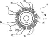
ステータコア24は、環状に形成された環状部24Aと、環状部24Aの外周部から径方向外側に向けて突出すると共に周方向に沿って等間隔に配置された複数(本実施形態では12個)のティース部24Bと、を備えている。また、各々のティース部24Bには、線状(針金状)に形成された導電性の部材の表面に絶縁性の被膜を有する巻線26が巻回されている。これにより、各々のティース部24Bのまわりには、それぞれコイル28が形成されている。
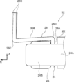
図2に示されるように、コイル28を形成した各々の巻線26においてステータコア24側から導出された部分は所定の形状(略N字状)に折り曲げられている。具体的には、巻線26においてステータコア24側から導出された部分は、ステータコア24に対して軸方向一方側へ延出する第1延出部26Aと、第1延出部26Aにおける軸方向一方側の端部から径方向外側へ延出すると共に径方向外側に向かうにつれて軸方向他方側に傾斜された第2延出部26Bと、を備えている。また、巻線26においてステータコア24側から導出された部分は、第2延出部26Bにおける径方向外側の端部から軸方向一方側へ向けて延出すると共に軸方向一方側の端部が回路装置18の一部を構成する回路基板44(図3参照)にハンダ付けにて接続される第3延出部26Cを備えている。そして、本実施形態では、第1延出部26Aと第2延出部26Bとの境目である内側屈曲部26Dが、第2延出部26Bと第3延出部26Cとの境目である外側屈曲部26Eに対して軸方向一方側に配置されている。
(ロータ14の構成)
図1に示されるように、ロータ14は、略有底円筒状に形成されたロータハウジング30と、ロータハウジング30に固定されたロータマグネット32と、を含んで構成されている。ロータハウジング30は、円板状に形成された底壁30Aと、底壁30Aの外周端から軸方向一方側へ屈曲して延びると共に径方向内側の面にロータマグネット32が固定される周壁30Bと、を備えている。また、ロータハウジング30の軸心部には、一対のベアリング34が圧入等により固定されている。そして、この一対のベアリング34が、後述するセンタピース16に固定された軸部材36に挿入されることで、ロータハウジング30が一対のベアリング34を介して軸部材36に支持されると共にロータハウジング30に固定されたロータマグネット32とステータ12とが径方向に対向して配置されるようになっている。
図1に示されるように、ロータ14は、略有底円筒状に形成されたロータハウジング30と、ロータハウジング30に固定されたロータマグネット32と、を含んで構成されている。ロータハウジング30は、円板状に形成された底壁30Aと、底壁30Aの外周端から軸方向一方側へ屈曲して延びると共に径方向内側の面にロータマグネット32が固定される周壁30Bと、を備えている。また、ロータハウジング30の軸心部には、一対のベアリング34が圧入等により固定されている。そして、この一対のベアリング34が、後述するセンタピース16に固定された軸部材36に挿入されることで、ロータハウジング30が一対のベアリング34を介して軸部材36に支持されると共にロータハウジング30に固定されたロータマグネット32とステータ12とが径方向に対向して配置されるようになっている。
(センタピース16の構成)
第1の部材としてのセンタピース16は、アルミニウム合金等を用いて形成されている。このセンタピース16には、軸方向他方側へ向けて突出すると共に前述の軸部材36が圧入により固定されるボス部16Aが立設されている。また、センタピース16における軸方向他方側には、前述のステータ12がステータ固定ボルト38等を介して固定されている。さらに、センタピース16における軸方向一方側には、後述する回路装置18が回路装置固定ボルト40等を介して固定されている。また、センタピース16における軸方向他方側の外周部には、後述するシール材50(図9参照)が塗布される凹溝16Bが形成されている。
第1の部材としてのセンタピース16は、アルミニウム合金等を用いて形成されている。このセンタピース16には、軸方向他方側へ向けて突出すると共に前述の軸部材36が圧入により固定されるボス部16Aが立設されている。また、センタピース16における軸方向他方側には、前述のステータ12がステータ固定ボルト38等を介して固定されている。さらに、センタピース16における軸方向一方側には、後述する回路装置18が回路装置固定ボルト40等を介して固定されている。また、センタピース16における軸方向他方側の外周部には、後述するシール材50(図9参照)が塗布される凹溝16Bが形成されている。
図3及び図4に示されるように、センタピース16には、軸方向一方側が開放されていると共に軸方向視で弓形に湾曲された長尺状の凹部16Cが形成されている。この凹部16Cの底16C1には、巻線26の第3延出部26Cが挿通される複数(本実施形態では3つの)のセンタピース側巻線挿通孔16Dが形成されている。この凹部16Cの底16C1に形成された複数のセンタピース側巻線挿通孔16Dは、凹部16Cの長手方向に沿って間隔をあけて配置されている。なお、センタピース16には、巻線26の第3延出部26Cの数に対応する数だけの凹部16C及びセンタピース側巻線挿通孔16Dが形成されている。
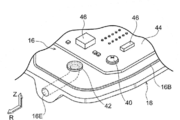
図5に示されるように、センタピース16の外周部には、回路装置18が配置される空間であるセンタピース16とカバー20(図1参照)との間の空間と当該空間の外側の空間とを連通する連通孔16Eが形成されている。この連通孔16Eの一方側は、回路装置18が配置される空間に軸方向一方側に向けて開口されており、連通孔16Eの他方側は、回路装置18が配置される空間の外側の空間に径方向外側に向けて開口されている。また、連通孔16Eにおける回路装置が配置される空間側の端部は、気体が透過可能でかつ液体が透過し難い素材を用いて形成されたフィルタ42により閉止されている。なお、フィルタ42の素材としては一例としてゴアテックス(登録商標)等が用いられている。
(回路装置18の構成)
図1及び図5に示されるように、回路装置18は、センタピース16に対してステータ12が固定された側とは反対側に配置されている。この回路装置18は、ステータ12(巻線26)への通電を制御する制御回路を構成する回路基板44及び複数の回路素子46を含んで構成されている。
図1及び図5に示されるように、回路装置18は、センタピース16に対してステータ12が固定された側とは反対側に配置されている。この回路装置18は、ステータ12(巻線26)への通電を制御する制御回路を構成する回路基板44及び複数の回路素子46を含んで構成されている。
回路基板44は、軸方向を厚み方向とする矩形板状に形成されており、この回路基板44は、絶縁性の材料を用いて形成された基板本体上に導電パターン部が形成されることによって構成されている。また、図3及び図4に示されるように、回路基板44には、センタピース16に形成されたセンタピース側巻線挿通孔16Dを通過した巻線26の第3延出部26Cの端部がハンダ付けにて接続される接続部44Aが設けられている。なお、回路基板44には、センタピース16に取付けられたコネクタ48(図1参照)を介して給電されるようになっている。
(カバー20の構成)
図1に示されるように、第2の部材としてのカバー20は、センタピース16側が開放された有底箱状に形成されている。このカバー20が、センタピース16にシール材50(図9参照)を介して接合されることで、カバー20とセンタピース16との間に回路装置18が配置される空間が形成されるようになっている。具体的には、カバー20は、センタピース16に固定された回路基板44と軸方向に対向して径方向に延在する底壁20Aと、底壁20Aの外周端からセンタピース16側へ向けて屈曲して延びる側壁20Bと、側壁20Bのセンタピース16側の端から径方向外側に向けて延びるフランジ部20Cと、を備えている。また、フランジ部20Cには、センタピース16に形成された凹溝16Bに対応する凸状部20Dが形成されている。
図1に示されるように、第2の部材としてのカバー20は、センタピース16側が開放された有底箱状に形成されている。このカバー20が、センタピース16にシール材50(図9参照)を介して接合されることで、カバー20とセンタピース16との間に回路装置18が配置される空間が形成されるようになっている。具体的には、カバー20は、センタピース16に固定された回路基板44と軸方向に対向して径方向に延在する底壁20Aと、底壁20Aの外周端からセンタピース16側へ向けて屈曲して延びる側壁20Bと、側壁20Bのセンタピース16側の端から径方向外側に向けて延びるフランジ部20Cと、を備えている。また、フランジ部20Cには、センタピース16に形成された凹溝16Bに対応する凸状部20Dが形成されている。
(キャップ52の構成)
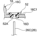
図4に示されるように、センタピース16におけるセンタピース側巻線挿通孔16Dの周縁部には、絶縁性の材料を用いて形成されたキャップ52が取付けられている。このキャップ52は、軸心部に巻線26の第3延出部26Cが挿通されるキャップ側巻線挿通孔52Aが形成された筒状に形成されている。
図4に示されるように、センタピース16におけるセンタピース側巻線挿通孔16Dの周縁部には、絶縁性の材料を用いて形成されたキャップ52が取付けられている。このキャップ52は、軸心部に巻線26の第3延出部26Cが挿通されるキャップ側巻線挿通孔52Aが形成された筒状に形成されている。
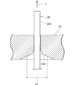
キャップ側巻線挿通孔52Aにおけるステータ12側(軸方向他方側)の部分は、軸方向一方側へ向けて次第に窄まる漏斗状に形成されている。これにより、キャップ側巻線挿通孔52Aにおける軸方向他方側の部分の内径D1が、軸方向一方側に向かうにつれて次第に小さくなっている。また、キャップ側巻線挿通孔52Aにおける回路装置18側(軸方向一方側)の部分の内径D2は、キャップ側巻線挿通孔52Aにおける軸方向の中央部の内径D3に比べて大きな内径に設定されている。なお、キャップ側巻線挿通孔52Aにおける軸方向の中央部の内径D3は、巻線26の外径D4と略同一の内径とされている。
(ポッティング部53の構成)
図3及び図4に示されるように、本実施形態では、センタピース16に形成された凹部16C内にポッティング部53が形成されることで、センタピース側巻線挿通孔16Dとキャップ52との間に形成された微小な隙間及びキャップ52と巻線26との間に形成された微小な隙間が塞がれている。なお、ポッティング部53を形成するポッティング材は、紫外線を照射することで容易に硬化させることが可能なシリコン樹脂である。
図3及び図4に示されるように、本実施形態では、センタピース16に形成された凹部16C内にポッティング部53が形成されることで、センタピース側巻線挿通孔16Dとキャップ52との間に形成された微小な隙間及びキャップ52と巻線26との間に形成された微小な隙間が塞がれている。なお、ポッティング部53を形成するポッティング材は、紫外線を照射することで容易に硬化させることが可能なシリコン樹脂である。
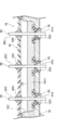
図3に示されるように、本実施形態では、シリコン樹脂がセンタピース16に形成された凹部16C内に注入されて、紫外線が凹部16Cに注入されたシリコン樹脂に照射されることで、単一のポッティング部53が凹部16Cの内部に形成される。これにより、凹部16Cの底16C1に形成された3つのセンタピース側巻線挿通孔16Dの周縁部に形成された上記の隙間が単一のポッティング部53によって塞がれる。なお、ポッティング部53の凹部16Cの底16C1に対する軸方向への高さ(深さ)Hは、当該ポッティング部53からキャップ52が露出しない程度の高さに設定されている。
(巻線端末部の成形方法)
次に、図6及び図7を用いて、コイル28を形成した各々の巻線26においてステータコア24側から導出された部分の成形方法について説明する。
次に、図6及び図7を用いて、コイル28を形成した各々の巻線26においてステータコア24側から導出された部分の成形方法について説明する。
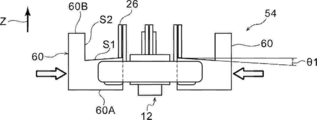
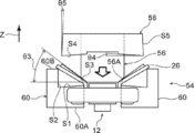
図6A~図6Cに示されるように、本実施形態では、ステータコア24の各々のティース部24Bの間に挿入されるバックアップ54と、巻線26をバックアップ54との間で挟み込む第1曲げ治具56及び第2曲げ治具58と、含んで構成されたプレス装置によって、コイル28を形成した各々の巻線26においてステータコア24側から導出された部分が所定の形状に折り曲げられる。
バックアップ54は、周方向に分割された複数のバックアップ構成ブロック60により構成されている。バックアップ構成ブロック60は、各々のティース部24Bの間に配置される部分を有するティース部間挿入部60Aと、ティース部間挿入部60Aの径方向外側から軸方向一方側へ延びる外周壁部60Bと、を有することにより、側面視で(径方向外側から見て)略L字状に形成されている。ティース部間挿入部60Aにおける軸方向一方側の面S1は、径方向外側に向かうにつれて軸方向他方側へ傾斜されている。一例として、ティース部間挿入部60Aにおける軸方向一方側の面S1の径方向に対する角度θ1は略4degに設定されている。また、外周壁部60Bの径方向内側の面S2は軸方向に沿って延在している。
第1曲げ治具56は、略円柱状に形成されており、この第1曲げ治具56の軸方向他方側の端部の径方向外側の端部は、軸方向他方側に向かうにつれて窄まる窄み部56Aとされている。また、窄み部56Aの外周面S3の径方向に対する傾斜角度θ3は略45degに設定されている。
第2曲げ治具58は、第1曲げ治具56が挿入される環状のブロック状に形成されている。この第2曲げ治具58における軸方向他方側の面S4は、バックアップ構成ブロック60のティース部間挿入部60Aにおける軸方向一方側の面S1に対応している。すなわち、第2曲げ治具58における軸方向他方側の面S4の径方向に対する傾斜角度S4は略4degに設定されている。また、第2曲げ治具58における径方向外側の面S5は、バックアップ構成ブロック60の外周壁部60Bの径方向内側の面S2に対して若干傾斜されている。すなわち、第2曲げ治具58における径方向外側の面S5の軸方向に対する径方向内側への傾斜角度θ5は略1.5degに設定されている。この傾斜角度θ5は、図2に示された巻線26において二点鎖線で示された状態から実線で示された状態へのスプリングバックを考慮して設定されている。
そして、図6Aに示されるように、コイル形成工程を経た後の状態では、コイル28を形成した各々の巻線26においてステータコア24側から導出された部分が軸方向一方側へ直線状に延出されている。この状態のステータ12がプレス装置にセットされた後に、各々のバックアップ構成ブロック60が径方向内側に移動される。これにより、各々のバックアップ構成ブロック60の各々のティース部間挿入部60Aの一部がステータコア24の各々のティース部24Bの間に配置される。
次いで、図6Bに示されるように、第1曲げ治具56が軸方向他方側へ移動されることで、コイル28を形成した各々の巻線26においてステータコア24側から導出された部分の基端側(軸方向他方側)が第1曲げ治具56の窄み部56Aの外周面S3に押圧される。これにより、コイル28を形成した各々の巻線26においてステータコア24側から導出された部分が、窄み部56Aの外周面S3に対応する角度(軸方向に対して略45deg)傾斜される。
次いで、図6Cに示されるように、第2曲げ治具58が軸方向他方側へ移動されることで、コイル28を形成した各々の巻線26においてステータコア24側から導出された部分が、第2曲げ治具58の軸方向他方側の面S4及び径方向外側の面S5と、バックアップ構成ブロック60のティース部間挿入部60Aにおける軸方向一方側の面S1及び外周壁部60Bの径方向内側の面S2と、の間に挟み込まれることにより加圧される(巻線曲げ工程)。以上の工程を経て、コイル28を形成した各々の巻線26においてステータコア24側から導出された部分が、図7Aに示された状態に曲げられる。
また、前述の巻線曲げ工程を経た後に、巻線26の第2延出部26Bを第3延出部26Cの回りに傾倒させることで、図7Bに示されるように、第3延出部26Cをセンタピース16に形成されたセンタピース側巻線挿通孔16D(図3参照)と対応する位置に配置させる(巻線旋回工程)。そして、図8A及び図8Bに示されるように、予めキャップ52が取付けられたセンタピース16にステータ12を取付ける際に、巻線26の第3延出部26Cをセンタピース16に形成されたセンタピース側巻線挿通孔16D及びキャップ52に形成されたキャップ側巻線挿通孔52Aに挿通させる(ステータ取付工程)。次いで、図8Cに示されるように、シリコン樹脂をセンタピース16に形成された凹部16C内に注入して、紫外線を凹部16Cに注入されたシリコン樹脂に照射することで、ポッティング部53を凹部16Cの内部に形成する(ポッティング部形成工程)。次いで、図3に示されるように、巻線26の第3延出部26Cを回路装置18の一部を構成する回路基板44にハンダ付けにて接続する(巻線接続工程)。
(カバーの取付工程)
次に、図9を用いて、カバー20をセンタピース16に取付ける工程について説明する。なお、図9においては、センタピース16に形成された凹溝16B及びカバー20のフランジ部20Cに形成された凸状部20Dの図示を省略している。
次に、図9を用いて、カバー20をセンタピース16に取付ける工程について説明する。なお、図9においては、センタピース16に形成された凹溝16B及びカバー20のフランジ部20Cに形成された凸状部20Dの図示を省略している。
図9に示されるように、先ず吸引ポンプ62をセンタピース16に形成された連通孔16Eに接続する(ポンプ接続工程)。
次いで、センタピース16に形成された凹溝16B(図1参照)にシール材50を注入する。なお、凹溝16B内に注入されるシール材50の量は、凹溝16Bの開放端からシール材50が突出する程度の量である。なお、凹溝16Bに対応する部分をカバー20のフランジ部20Cに形成して、当該凹溝16Bに対応する部分にシール材50を塗布してもよい。
次いで、吸引ポンプ62を作動させることで、連通孔16Eを通じて回路装置18側の空気を引き込みながら、カバー20のフランジ部20Cをセンタピース16においてシール材50が塗布された部分に接合する(接合工程)
以上説明した工程及びその他の工程を経て本実施形態のモータユニット10が製造される。
(本実施形態の作用)
次に、本実施形態の作用について説明する。
次に、本実施形態の作用について説明する。
図1に示されるように、本実施形態のモータユニット10では、回路装置18によってステータ12(巻線26)への通電が制御されることで、ステータ12が回転磁界を発生する。そして、この回転磁界及びロータマグネット32の磁界の相互作用により、ロータ14が回転する。
ここで、本実施形態のモータユニット10では、図3に示されるように、巻線26の第3延出部26Cが、ステータ12を支持するセンタピース16に形成されたセンタピース側巻線挿通孔16D及びキャップ52に形成されたキャップ側巻線挿通孔52Aに挿通されていると共に、センタピース16に形成された凹部16C内にポッティング部53が形成されることで、センタピース側巻線挿通孔16Dとキャップ52との間に形成された微小な隙間及びキャップ52と巻線26との間に形成された微小な隙間が塞がれている。これにより、ステータ12側に付着した水滴が、センタピース側巻線挿通孔16Dの周縁部を通じて回路装置18側へ浸入することを抑制することができる。特に、本実施形態では、ポッティング部53が巻線26の被膜に密着させた構成とすることにより、当該ポッティング部53と巻線26との接合状態を良好にすることができる。これにより、ステータ12側に付着した水滴が、ポッティング部53と巻線26との間を通じて回路装置18側へ浸入することを抑制することができる。
また、本実施形態では、複数(3つの)の第3延出部26Cの周縁部の隙間が、単一のポッティング部53によって塞がれる構成とされている。これにより、それぞれの隙間を塞ぐためのポッティング部53を形成する際の作業性を良好にすることができる。
これに加えて、本実施形態では、センタピース側巻線挿通孔16Dがセンタピース16に形成された凹部16Cの底に形成された構成とすることで、ポッティング部53を形成するためのポッティング材を凹部16C内に留めることができる。これにより、センタピース側巻線挿通孔16Dと巻線26との間に形成された隙間を塞ぐためのポッティング部53を形成する際の作業性を良好にすることができる。
さらに、本実施形態では、複数のセンタピース側巻線挿通孔16Dを単一の凹部16Cの底に形成された構成とすることで、センタピース側巻線挿通孔16Dと巻線26との間に形成された隙間を塞ぐためのポッティング部53を形成する際の作業性をより一層良好にすることができる。
また、本実施形態では、絶縁性のキャップ52をセンタピース側巻線挿通孔16Dと巻線26との間に設けることで、巻線26とセンタピース側巻線挿通孔16Dの周縁部との間の絶縁状態を容易に確保することができる。また、キャップ52に形成されたキャップ側巻線挿通孔52Aにおけるステータ12側の部分の内径D1をステータ12側から回路装置18側に向かうにつれて小さくなるように形成することで、巻線26をステータ12側から回路装置18側へ容易に挿通することができる。
さらに、本実施形態では、キャップ52に形成されたキャップ側巻線挿通孔52Aにおける回路装置18側の部分の内径D2をキャップ側巻線挿通孔52Aにおける軸方向の中央部の内径D3に比べて大きくすることで、ポッティング部53と巻線26に形成された被膜との接触面積を多くすることができる。これにより、ポッティング部53と巻線26に形成された被膜との接合強度を高めることができる。なお、図10に示されるように、キャップ52を軸方向に反転させた状態でセンタピース16に取付けることにより、ポッティング部53と巻線26に形成された被膜との接触面積を多くすることもできる。
なお、図3に示された本実施形態では、キャップ側巻線挿通孔52Aにおけるステータ12側の部分を漏斗状に形成することにより、キャップ側巻線挿通孔52Aにおける軸方向他方側の部分の内径D1が、軸方向一方側に向かうにつれて次第に小さくなるように構成した例について説明したが、本開示はこれに限定されない。例えば、図11に示されるように、キャップ側巻線挿通孔52Aにおけるステータ12側の部分を漏斗状に形成すると共に当該部分の軸方向の中間部を屈曲させた構成としてもよい。また、図12に示されるように、キャップ側巻線挿通孔52Aにおけるステータ12側の部分を漏斗状に形成すると共にその内周面を緩やかに湾曲させた構成としてもよい。
なお、本実施形態では、キャップ52をセンタピース16に取付けた例について説明したが、本開示はこれに限定されない。例えば、センタピース16に形成されたセンタピース側巻線挿通孔16Dの周縁部をキャップと同様の構成とすることにより、キャップ52を設けない構成としてもよい。
図2に示されるように、本実施形態のモータユニットの一部を構成するステータ12では、巻線26の第1延出部26Aと第2延出部26Bとの境目である内側屈曲部26Dが、第2延出部26Bと第3延出部26Cとの境目である外側屈曲部26Eに対して軸方向一方側に配置されている。これにより、内側屈曲部26Dと外側屈曲部26Eとが、回転軸方向の同位置に配置された構成に比べて、ステータ12におけるロータの回転径方向外側の部位を、センタピース16に近接して配置することが可能となる。その結果、モータユニット10の回転軸方向への体格の大型化を抑制することができる。
また、本実施形態では、巻線26の第1延出部26Aと第2延出部との間の部位である第2延出部26Bが、径方向外側に向かうにつれて軸方向他方側に傾斜されている。当該構成とすることにより、第2延出部26Bを湾曲させた場合に比べて、第2延出部26Bの長さを短くすることができる。これにより、巻線26においてステータコア24から延出している部分の回路装置までの配索経路が長くなることを抑制することができる。なお、第2延出部26Bを上記のように傾斜されるか否かは、センタピース16においてステータ12が固定される部分の構成を考慮して適宜設定すればよい。
さらに、本実施形態では、図6A~図6Cに示された巻線曲げ工程を経た後に、図7Bに示された巻線旋回工程を経ることにより、ステータ12をセンタピース16に取付ける際に、巻線26の第3延出部26Cをセンタピース16に形成されたセンタピース側巻線挿通孔16D及びキャップ52に形成されたキャップ側巻線挿通孔52Aに容易に挿通させることができる。なお、巻線旋回工程をモータユニットまるの製造工程に組み込むか否かについては、センタピース16に形成されたセンタピース側巻線挿通孔16Dの配置を考慮して選択すればよい。
図1に示されるように、本実施形態のモータユニット10では、回路装置18がセンタピース16とカバー20との間に形成された空間内に配置されている。また、センタピース16とカバー20との間には、シール材50が介在している。これにより、水滴がセンタピースとカバーとの間から回路装置18が配置された空間に浸入することが抑制されている。
ところで、図9に示されるように、シール材50がセンタピース16塗布された状態で、カバー20をセンタピース16に取付ける際においては、シール材50がカバー20とセンタピース16との間で潰される際に、センタピース16とカバー20との間の圧力が高まることが考えられる。これにより、センタピース16とカバー20との間に介在されるシール材50が飛散することが考えられる。すなわち、センタピース16とカバー20との間においてシール材50が欠損する箇所が生じることが考えられる。
しかしながら、本実施形態では、センタピース16とカバー20との間に形成された空間と当該空間の外側の空間とを連通すると共に当該外側の空間側の部分が径方向外側へ向けて開放された連通孔16Eが、センタピースに形成されている。これにより、吸引ポンプ62を連通孔16Eにおける回路装置18が配置される側とは反対側の部分に容易に接続することができる。そして、吸引ポンプ62によって、回路装置18側の空気を引き込みながら、カバー20をセンタピース16に取付けることで、シール材50がカバー20とセンタピース16との間で潰される際に、センタピース16とカバー20との間の空間の圧力が高まることを抑制することができる。これにより、センタピース16とカバー20との間においてシール材を所望の状態で介在させることができる。
また、本実施形態では、連通孔16Eにおける回路装置18が配置される空間側の端部が、前述の特定を有するフィルタ42により閉止されている。当該構成では、シール材50がカバー20とセンタピース16との間で潰される際に、センタピース16とカバー20との間の空間の圧力が高まり易い。しかしながら、本実施形態では、連通孔16Eに接続された吸引ポンプ62によって、回路装置18側の空気を引き込みながら、カバー20をセンタピース16に取付けることで、シール材50がカバー20とセンタピース16との間で潰される際に、センタピース16とカバー20との間の空間の圧力が高まることを抑制することができる。これにより、上記フィルタ42が設けられた構成においても、センタピース16とカバー20との間においてシール材50を所望の状態で介在させることができる。
なお、上記フィルタ42を設けるか否かについては、モータユニット10が配置される環境や姿勢等を考慮して適宜選択すればよい。
以上、本開示の一実施形態について説明したが、本開示は、上記に限定されるものでなく、その主旨を逸脱しない範囲内において上記以外にも種々変形して実施することが可能であることは勿論である。
2016年3月9日に出願された日本国特許出願2016-045700号、及び日本国特許出願2016-045701号の開示は、その全体が参照により本明細書に取り込まれる。
本明細書に記載された全ての文献、特許出願、および技術規格は、個々の文献、特許出願、および技術規格が参照により取り込まれることが具体的かつ個々に記された場合と同程度に、本明細書中に参照により取り込まれる。
Claims (10)
- 導電性の部材の表面に絶縁性の被膜を有する巻線が巻回されることで形成されたコイルを有するステータと、
前記ステータが発生する回転磁界を受けて回転するロータと、
前記ステータを支持すると共に前記巻線が挿通されるセンタピース側巻線挿通孔が形成されたセンタピースと、
前記センタピースに対してステータが固定された側とは反対側に配置され、前記センタピース側巻線挿通孔を通過した前記巻線が接続される接続部を有し、前記巻線への通電を制御する回路装置と、
ポッティング材を用いて形成され、一部が前記巻線の被膜に密着された状態で、前記センタピース側巻線挿通孔と前記巻線との間に形成された隙間を塞ぐポッティング部と、
を備えたモータ。 - 前記センタピースには、複数の前記センタピース側巻線挿通孔が形成されており、
複数の前記センタピース側巻線挿通孔と複数の前記センタピース側巻線挿通孔にそれぞれ挿通された前記巻線との間に形成されたそれぞれの隙間が、単一の前記ポッティング部によって塞がれている請求項1記載のモータ。 - 前記センタピースには、前記ロータの回転軸方向の一方側が開放された凹部が形成されており、
前記センタピース側巻線挿通孔が、前記凹部の底に形成されている請求項1又は請求項2記載のモータ。 - 複数の前記センタピース側巻線挿通孔が、単一の前記凹部の底に形成されている請求項3記載のモータ。
- 前記センタピース側巻線挿通孔と前記巻線との間には、前記巻線が挿通されるキャップ側巻線挿通孔が形成された絶縁性のキャップが設けられており、
前記キャップ側巻線挿通孔における前記ステータ側の部分の内径が、前記ステータ側から前記回路装置側に向かうにつれて小さくなっている請求項1~請求項4のいずれか1項に記載のモータ。 - 前記キャップ側巻線挿通孔における前記回路装置側の部分の内径が、前記キャップ側巻線挿通孔における前記ロータの回転軸方向の中央部の内径に比べて大きくなっており、
前記ポッティング部が、前記センタピースに対して前記回路装置側に設けられている請求項5記載のモータ。 - ロータマグネットを有すると共に軸線回りに回転可能に支持されたロータと、
前記ロータマグネットと前記ロータの回転径方向に対向して配置されたステータコアと、前記ステータコアに対して前記ロータの回転軸方向一方側へ延出する第1延出部と、該第1延出部における前記ロータの回転軸方向一方側の端部から前記ロータの回転径方向外側へ延出する第2延出部と、該第2延出部における前記ロータの回転径方向外側の端部から前記ロータの回転軸方向一方側へ向けて延出すると共に回路装置に接続される第3延出部と、を有し、前記ステータコアの回りにコイルを形成するとともに、前記第1延出部と前記第2延出部との境目が、前記第2延出部と前記第3延出部との境目に対して前記ロータの回転軸方向一方側に配置された巻線と、を有するステータと、
を備えたモータ。 - 前記第2延出部が、前記ロータの回転径方向外側に向かうにつれて前記ロータの回転軸方向他方側へ傾斜されている請求項7記載のモータ。
- 請求項7又は請求項8記載のモータの製造方法に適用され、
前記ステータコアの回りに巻線を巻回することで、前記ステータコアの回りにコイルを形成するコイル形成工程と、
前記コイルを形成した巻線において前記ステータコアから延出している部分を加圧することで、前記第1延出部、前記第2延出部及び前記第3延出部を形成すると共に前記第1延出部と前記第2延出部との境目を前記第2延出部と前記第3延出部との境目に対して前記ロータの回転軸方向一方側に配置する巻線曲げ工程と、
前記第3延出部を前記回路装置に接続する巻線接続工程と、
を有するモータの製造方法。 - 前記ステータは、前記第3延出部が挿通されるセンタピース側巻線挿通孔が形成されたセンタピースに支持され、
前記巻線曲げ工程を経た後に、前記第2延出部を前記第3延出部の回りに傾倒させることで、前記第3延出部をセンタピース側巻線挿通孔と対応する位置に配置させる巻線旋回工程と、
前記ステータを前記センタピースに取付けるステータ取付工程と、
をさらに有する、
請求項9記載のモータの製造方法。
Priority Applications (5)
| Application Number | Priority Date | Filing Date | Title |
|---|---|---|---|
| DE112017001225.2T DE112017001225T5 (de) | 2016-03-09 | 2017-03-06 | Motor und Herstellungsverfahren für einen Motor |
| CN202010710000.6A CN112018964B (zh) | 2016-03-09 | 2017-03-06 | 电动机及电动机的制造方法 |
| CN201780015376.1A CN108702056B (zh) | 2016-03-09 | 2017-03-06 | 电动机及电动机的制造方法 |
| US16/082,540 US11088585B2 (en) | 2016-03-09 | 2017-03-06 | Motor with potting section and hole provided with cap through which winding is inserted |
| US17/361,732 US11715986B2 (en) | 2016-03-09 | 2021-06-29 | Motor including winding including inner bent portion and outer bent portion and method of manufacturing motor |
Applications Claiming Priority (4)
| Application Number | Priority Date | Filing Date | Title |
|---|---|---|---|
| JP2016045700A JP6720589B2 (ja) | 2016-03-09 | 2016-03-09 | モータ |
| JP2016-045701 | 2016-03-09 | ||
| JP2016045701A JP6720590B2 (ja) | 2016-03-09 | 2016-03-09 | モータ及びモータの製造方法 |
| JP2016-045700 | 2016-03-09 |
Related Child Applications (2)
| Application Number | Title | Priority Date | Filing Date |
|---|---|---|---|
| US16/082,540 A-371-Of-International US11088585B2 (en) | 2016-03-09 | 2017-03-06 | Motor with potting section and hole provided with cap through which winding is inserted |
| US17/361,732 Continuation US11715986B2 (en) | 2016-03-09 | 2021-06-29 | Motor including winding including inner bent portion and outer bent portion and method of manufacturing motor |
Publications (1)
| Publication Number | Publication Date |
|---|---|
| WO2017154838A1 true WO2017154838A1 (ja) | 2017-09-14 |
Family
ID=59790295
Family Applications (1)
| Application Number | Title | Priority Date | Filing Date |
|---|---|---|---|
| PCT/JP2017/008792 Ceased WO2017154838A1 (ja) | 2016-03-09 | 2017-03-06 | モータ及びモータの製造方法 |
Country Status (4)
| Country | Link |
|---|---|
| US (2) | US11088585B2 (ja) |
| CN (2) | CN108702056B (ja) |
| DE (1) | DE112017001225T5 (ja) |
| WO (1) | WO2017154838A1 (ja) |
Families Citing this family (7)
| Publication number | Priority date | Publication date | Assignee | Title |
|---|---|---|---|---|
| EP3297143B1 (en) * | 2015-05-15 | 2019-11-06 | Mitsubishi Electric Corporation | Vehicle ac power generator |
| IT201700067309A1 (it) * | 2017-06-16 | 2018-12-16 | I M E Ind Motori Elettrici S P A | Sistema ventilatore da incasso |
| CN115315887A (zh) * | 2020-03-25 | 2022-11-08 | 日本电产株式会社 | 马达 |
| JP2023050858A (ja) * | 2021-09-30 | 2023-04-11 | 日本電産株式会社 | モータ |
| DE102021214468A1 (de) | 2021-12-15 | 2023-06-15 | Robert Bosch Gesellschaft mit beschränkter Haftung | Pumpe, Motoreinheit und Verfahren zur Herstellung der Motoreinheit |
| CN116846122A (zh) * | 2022-03-25 | 2023-10-03 | 台达电子工业股份有限公司 | 马达组件 |
| US20250096638A1 (en) * | 2023-09-14 | 2025-03-20 | Mahle International Gmbh | Electric scroll compressor with motor connector assembly and motor connector assembly for electric scroll compressor |
Citations (3)
| Publication number | Priority date | Publication date | Assignee | Title |
|---|---|---|---|---|
| JPH04134124U (ja) * | 1991-05-28 | 1992-12-14 | エヌオーケー株式会社 | グロメツト |
| JP2002064028A (ja) * | 2000-08-16 | 2002-02-28 | Toyota Motor Corp | コイルおよびリード形成装置並びにリード形成方法 |
| JP2015142455A (ja) * | 2014-01-29 | 2015-08-03 | アスモ株式会社 | ブラシレスモータ |
Family Cites Families (67)
| Publication number | Priority date | Publication date | Assignee | Title |
|---|---|---|---|---|
| US4115915A (en) * | 1975-07-31 | 1978-09-26 | General Electric Company | Process for manufacturing motor having windings constructed for automated assembly |
| US4535373A (en) * | 1980-12-29 | 1985-08-13 | Papst-Motoren Gmbh & Co. Kg | Labyrinth seal in disk storage drive |
| US4658312A (en) * | 1981-09-07 | 1987-04-14 | Papst-Motoren Gmbh & Co. K.G. | Disk storage drive |
| US5173814A (en) * | 1981-09-07 | 1992-12-22 | Papst-Motoren Gmbh & Co. Kg | Disk storage drive having internal electrical connection passages and contamination seals at ends of the motor |
| USRE38662E1 (en) * | 1980-05-10 | 2004-11-30 | Papst Licensing Gmbh & Co. Kg | Disk storage device having a sealed bearing tube |
| JPS6294612U (ja) * | 1985-12-03 | 1987-06-17 | ||
| US5448117A (en) * | 1993-02-25 | 1995-09-05 | Consulier Engineering, Inc. | Stepper motor |
| US5291087A (en) * | 1993-03-03 | 1994-03-01 | Westinghouse Electric Corp. | Sealed electric motor assembly |
| US5394043A (en) * | 1993-06-29 | 1995-02-28 | American Precision Industries Inc. | High speed brushless motor |
| US5548458A (en) * | 1994-05-04 | 1996-08-20 | Seagate Technology, Inc. | Support flange having electrical contacts to provide electrical continuity upon spindle motor mounting to base |
| US5685062A (en) * | 1994-07-05 | 1997-11-11 | Ford Motor Company | Self-assembly fabrication method for planar micro-motor |
| US5874796A (en) * | 1995-02-10 | 1999-02-23 | Petersen; Christian C. | Permanent magnet D.C. motor having a radially-disposed working flux gap |
| US5659217A (en) * | 1995-02-10 | 1997-08-19 | Petersen; Christian C. | Permanent magnet d.c. motor having a radially-disposed working flux gap |
| US5806169A (en) * | 1995-04-03 | 1998-09-15 | Trago; Bradley A. | Method of fabricating an injected molded motor assembly |
| WO1997009659A1 (en) * | 1995-09-05 | 1997-03-13 | Cts Corporation | Rotary position sensor with insert molded coil winding |
| US6137202A (en) * | 1999-04-27 | 2000-10-24 | General Electric Company | Insulated coil and coiled frame and method for making same |
| DE20105050U1 (de) * | 2000-05-27 | 2001-06-28 | Papst-Motoren GmbH & Co. KG, 78112 St Georgen | Motoranordnung |
| US6445095B1 (en) * | 2001-01-11 | 2002-09-03 | Ford Global Technologies, Inc. | Electric machine with laminated cooling rings |
| JP2003142455A (ja) | 2001-10-31 | 2003-05-16 | Matsushita Electric Ind Co Ltd | プラズマ処理装置及び処理方法 |
| JP3808434B2 (ja) * | 2002-12-27 | 2006-08-09 | 三菱電機株式会社 | 回転電機の固定子 |
| JP4108488B2 (ja) * | 2003-01-17 | 2008-06-25 | 山洋電気株式会社 | 防水型ブラシレスファンモータ |
| GB0327023D0 (en) * | 2003-11-20 | 2003-12-24 | Head Philip | Electric motors for powering downhole tools |
| JP4496010B2 (ja) * | 2004-05-20 | 2010-07-07 | 株式会社東芝 | モータ |
| US7474024B2 (en) * | 2004-09-15 | 2009-01-06 | Aisan Kogyo Kabushiki Kaisha | Electronic control unit and electric pump |
| DE102004044986A1 (de) * | 2004-09-16 | 2006-04-06 | Siemens Ag | Permanenterregte Synchronmaschine mit Flachdrahtwicklungen |
| JP2008541691A (ja) * | 2005-05-17 | 2008-11-20 | フェデラル−モーグル コーポレイション | 封入された回路基板を有するbldcモータおよびポンプアセンブリ |
| US7256522B2 (en) * | 2005-05-31 | 2007-08-14 | Regal-Beloit Corporation | Motor control packaging for an electric motor |
| JP2007049891A (ja) * | 2005-07-11 | 2007-02-22 | Nippon Densan Corp | ステータ部の製造方法およびモータ |
| US8156757B2 (en) * | 2006-10-06 | 2012-04-17 | Aff-Mcquay Inc. | High capacity chiller compressor |
| JP4340740B2 (ja) * | 2007-07-19 | 2009-10-07 | トヨタ自動車株式会社 | 電動機のステータに用いられる接続線、その接続線を備えたステータおよびその接続線の曲げ方法 |
| JP4730367B2 (ja) * | 2007-08-21 | 2011-07-20 | トヨタ自動車株式会社 | 分割固定子製造方法 |
| JP4331231B2 (ja) * | 2007-10-19 | 2009-09-16 | トヨタ自動車株式会社 | ステータおよび回転電機 |
| JP4404145B2 (ja) * | 2008-01-16 | 2010-01-27 | トヨタ自動車株式会社 | 分割固定子製造方法 |
| JP5237048B2 (ja) * | 2008-02-13 | 2013-07-17 | 日立オートモティブシステムズ株式会社 | 回転電機、および固定子巻線 |
| US9318934B2 (en) * | 2009-03-20 | 2016-04-19 | Kaltenbach & Voigt Gmbh | Electric motor arrangement for a medical, especially dental, tool holder |
| JP5624330B2 (ja) * | 2009-06-24 | 2014-11-12 | 株式会社デンソー | モータ |
| US8519582B2 (en) * | 2009-09-29 | 2013-08-27 | Regal Beloit America, Inc. | Air cooled electric motor |
| JP5493906B2 (ja) * | 2010-01-21 | 2014-05-14 | 株式会社デンソー | 回転電機の固定子 |
| JP5740930B2 (ja) * | 2010-03-03 | 2015-07-01 | 日本電産株式会社 | ステータ及びモータ |
| JP5370245B2 (ja) * | 2010-03-31 | 2013-12-18 | 株式会社デンソー | 回転電機の固定子の製造方法 |
| JP5585819B2 (ja) * | 2010-03-31 | 2014-09-10 | 株式会社デンソー | 回転電機の固定子 |
| EP2580850B1 (en) * | 2010-06-14 | 2021-11-10 | Black & Decker, Inc. | Control unit for brushless motor in a power tool |
| TW201244339A (en) * | 2011-04-20 | 2012-11-01 | Delta Electronics Inc | Motor and fan using the same |
| JP5845862B2 (ja) * | 2011-06-17 | 2016-01-20 | 日本電産株式会社 | モータ |
| US9343930B2 (en) * | 2012-05-25 | 2016-05-17 | Baldor Electric Company | Segmented stator assembly |
| JP6033582B2 (ja) * | 2012-06-22 | 2016-11-30 | アイシン・エィ・ダブリュ株式会社 | ステータおよびステータの製造方法 |
| DE112013003484T5 (de) * | 2012-07-11 | 2015-04-02 | Remy Technologies Llc | Integrierter Phasenanschlussisolator mit einzelnem Phasentrenner |
| DE112013003663B4 (de) * | 2012-07-26 | 2025-01-23 | Mitsubishi Electric Corporation | Elektrische Rotationsmaschine |
| JP5554383B2 (ja) * | 2012-09-11 | 2014-07-23 | 三菱電機株式会社 | 回転電機の固定子、及びその固定子の製造方法 |
| US9169833B2 (en) * | 2012-10-04 | 2015-10-27 | Carter Fuel Systems, Llc | Device for fastening and electrically connecting a circuit board to a motor |
| JP2014093880A (ja) * | 2012-11-05 | 2014-05-19 | Denso Corp | 回転電機 |
| US9722464B2 (en) * | 2013-03-13 | 2017-08-01 | Honeywell International Inc. | Gas turbine engine actuation systems including high temperature actuators and methods for the manufacture thereof |
| JP2014204477A (ja) | 2013-04-01 | 2014-10-27 | アスモ株式会社 | ブラシレスモータ及び巻線端末保持方法 |
| JP5944046B2 (ja) * | 2013-04-08 | 2016-07-05 | 三菱電機株式会社 | 回転電機の固定子 |
| CN103746488B (zh) * | 2013-10-16 | 2016-02-03 | 广东威灵电机制造有限公司 | 电机、电机定子绕组的防水结构及其加工工艺 |
| CN105830314B (zh) * | 2013-12-16 | 2019-01-22 | 三菱电机株式会社 | 机电一体型驱动装置及其制造方法 |
| JP6011557B2 (ja) * | 2014-01-31 | 2016-10-19 | 株式会社デンソー | 駆動装置 |
| EP3128648A4 (en) * | 2014-03-31 | 2017-11-01 | Honda Motor Co., Ltd. | Stator for rotary electric machine |
| JP6331873B2 (ja) | 2014-08-22 | 2018-05-30 | 沖電気工業株式会社 | シフト管理システム、端末装置、情報処理システム、情報処理方法及びプログラム |
| JP6442924B2 (ja) | 2014-08-22 | 2018-12-26 | 大日本印刷株式会社 | プリント端末、コンテンツ製造方法、プログラム、及び、コンテンツプリントシステム |
| JP6361451B2 (ja) * | 2014-10-16 | 2018-07-25 | 株式会社デンソー | 電気装置および電気装置の製造方法 |
| US20180115211A1 (en) * | 2015-03-31 | 2018-04-26 | Mitsubishi Electric Corporation | Rotary electric machine |
| JP2016214034A (ja) * | 2015-05-13 | 2016-12-15 | 株式会社デンソー | 回転電機及びその製造方法 |
| US20170317562A1 (en) * | 2016-04-29 | 2017-11-02 | Denso Corporation | Rotating electric machine integrated with controller |
| WO2018097205A1 (ja) * | 2016-11-23 | 2018-05-31 | 日本電産株式会社 | 車載用モータ、および電動パワーステアリング装置 |
| CN110178290B (zh) * | 2017-03-16 | 2021-09-07 | 爱信艾达株式会社 | 定子 |
| US11139722B2 (en) * | 2018-03-02 | 2021-10-05 | Black & Decker Inc. | Motor having an external heat sink for a power tool |
-
2017
- 2017-03-06 CN CN201780015376.1A patent/CN108702056B/zh active Active
- 2017-03-06 DE DE112017001225.2T patent/DE112017001225T5/de not_active Ceased
- 2017-03-06 CN CN202010710000.6A patent/CN112018964B/zh active Active
- 2017-03-06 US US16/082,540 patent/US11088585B2/en active Active
- 2017-03-06 WO PCT/JP2017/008792 patent/WO2017154838A1/ja not_active Ceased
-
2021
- 2021-06-29 US US17/361,732 patent/US11715986B2/en active Active
Patent Citations (3)
| Publication number | Priority date | Publication date | Assignee | Title |
|---|---|---|---|---|
| JPH04134124U (ja) * | 1991-05-28 | 1992-12-14 | エヌオーケー株式会社 | グロメツト |
| JP2002064028A (ja) * | 2000-08-16 | 2002-02-28 | Toyota Motor Corp | コイルおよびリード形成装置並びにリード形成方法 |
| JP2015142455A (ja) * | 2014-01-29 | 2015-08-03 | アスモ株式会社 | ブラシレスモータ |
Also Published As
| Publication number | Publication date |
|---|---|
| CN108702056A (zh) | 2018-10-23 |
| CN112018964A (zh) | 2020-12-01 |
| US11715986B2 (en) | 2023-08-01 |
| US20190097486A1 (en) | 2019-03-28 |
| CN108702056B (zh) | 2020-11-03 |
| DE112017001225T5 (de) | 2018-12-20 |
| US11088585B2 (en) | 2021-08-10 |
| US20210328476A1 (en) | 2021-10-21 |
| CN112018964B (zh) | 2023-05-23 |
Similar Documents
| Publication | Publication Date | Title |
|---|---|---|
| WO2017154838A1 (ja) | モータ及びモータの製造方法 | |
| CN110383643B (zh) | 模制马达 | |
| JP4468033B2 (ja) | 車両用エンジンのバルブタイミング可変装置用電動機 | |
| KR100529013B1 (ko) | 회전각도 검출기 | |
| US20210126505A1 (en) | Motor | |
| EP3536958A1 (en) | Electric pump | |
| CN103066738A (zh) | 用于电机的壳体部件 | |
| JP6338172B2 (ja) | ブラシレスモータ | |
| CN109716628B (zh) | 马达 | |
| JPWO2018025367A1 (ja) | 電動機および空気調和装置 | |
| JP2017163693A (ja) | モータ | |
| JP2010074958A (ja) | モータの製造方法及びモータ | |
| JP6642133B2 (ja) | モータの製造方法 | |
| JP5064215B2 (ja) | 電動機及びステータの製造方法並びに電動機の製造方法 | |
| CN114830504B (zh) | 旋转电动机 | |
| JP7405089B2 (ja) | モータ | |
| JP2017163694A (ja) | モータ及びモータの製造方法 | |
| CN109309425B (zh) | 马达 | |
| JP2020108183A (ja) | モータ | |
| JP2019030046A (ja) | モータ | |
| JP6680073B2 (ja) | ブラシレスモータ及びブラシレスモータの製造方法 | |
| JP2008099355A (ja) | モータ用軸受装置及び振動モータ | |
| CN112136265A (zh) | 模制马达 | |
| CN118739690A (zh) | 旋转电机和旋转电机的制造方法 | |
| KR20080078949A (ko) | 모터 |
Legal Events
| Date | Code | Title | Description |
|---|---|---|---|
| 121 | Ep: the epo has been informed by wipo that ep was designated in this application |
Ref document number: 17763178 Country of ref document: EP Kind code of ref document: A1 |
|
| 122 | Ep: pct application non-entry in european phase |
Ref document number: 17763178 Country of ref document: EP Kind code of ref document: A1 |