WO2017154673A1 - 基板洗浄装置、基板洗浄方法、基板処理装置および基板乾燥装置 - Google Patents
基板洗浄装置、基板洗浄方法、基板処理装置および基板乾燥装置 Download PDFInfo
- Publication number
- WO2017154673A1 WO2017154673A1 PCT/JP2017/007836 JP2017007836W WO2017154673A1 WO 2017154673 A1 WO2017154673 A1 WO 2017154673A1 JP 2017007836 W JP2017007836 W JP 2017007836W WO 2017154673 A1 WO2017154673 A1 WO 2017154673A1
- Authority
- WO
- WIPO (PCT)
- Prior art keywords
- substrate
- cleaning
- cleaning liquid
- supply
- unit
- Prior art date
- Legal status (The legal status is an assumption and is not a legal conclusion. Google has not performed a legal analysis and makes no representation as to the accuracy of the status listed.)
- Ceased
Links
Images




























Classifications
-
- H—ELECTRICITY
- H10—SEMICONDUCTOR DEVICES; ELECTRIC SOLID-STATE DEVICES NOT OTHERWISE PROVIDED FOR
- H10P—GENERIC PROCESSES OR APPARATUS FOR THE MANUFACTURE OR TREATMENT OF DEVICES COVERED BY CLASS H10
- H10P72/00—Handling or holding of wafers, substrates or devices during manufacture or treatment thereof
- H10P72/04—Apparatus for manufacture or treatment
- H10P72/0402—Apparatus for fluid treatment
- H10P72/0406—Apparatus for fluid treatment for cleaning followed by drying, rinsing, stripping, blasting or the like
- H10P72/0411—Apparatus for fluid treatment for cleaning followed by drying, rinsing, stripping, blasting or the like for wet cleaning or washing
- H10P72/0414—Apparatus for fluid treatment for cleaning followed by drying, rinsing, stripping, blasting or the like for wet cleaning or washing using mainly spraying means, e.g. nozzles
-
- H—ELECTRICITY
- H10—SEMICONDUCTOR DEVICES; ELECTRIC SOLID-STATE DEVICES NOT OTHERWISE PROVIDED FOR
- H10P—GENERIC PROCESSES OR APPARATUS FOR THE MANUFACTURE OR TREATMENT OF DEVICES COVERED BY CLASS H10
- H10P72/00—Handling or holding of wafers, substrates or devices during manufacture or treatment thereof
- H10P72/04—Apparatus for manufacture or treatment
- H10P72/0402—Apparatus for fluid treatment
- H10P72/0406—Apparatus for fluid treatment for cleaning followed by drying, rinsing, stripping, blasting or the like
- H10P72/0411—Apparatus for fluid treatment for cleaning followed by drying, rinsing, stripping, blasting or the like for wet cleaning or washing
-
- B—PERFORMING OPERATIONS; TRANSPORTING
- B08—CLEANING
- B08B—CLEANING IN GENERAL; PREVENTION OF FOULING IN GENERAL
- B08B3/00—Cleaning by methods involving the use or presence of liquid or steam
- B08B3/02—Cleaning by the force of jets or sprays
-
- B—PERFORMING OPERATIONS; TRANSPORTING
- B08—CLEANING
- B08B—CLEANING IN GENERAL; PREVENTION OF FOULING IN GENERAL
- B08B3/00—Cleaning by methods involving the use or presence of liquid or steam
- B08B3/04—Cleaning involving contact with liquid
- B08B3/08—Cleaning involving contact with liquid the liquid having chemical or dissolving effect
-
- B—PERFORMING OPERATIONS; TRANSPORTING
- B08—CLEANING
- B08B—CLEANING IN GENERAL; PREVENTION OF FOULING IN GENERAL
- B08B3/00—Cleaning by methods involving the use or presence of liquid or steam
- B08B3/04—Cleaning involving contact with liquid
- B08B3/10—Cleaning involving contact with liquid with additional treatment of the liquid or of the object being cleaned, e.g. by heat, by electricity or by vibration
- B08B3/12—Cleaning involving contact with liquid with additional treatment of the liquid or of the object being cleaned, e.g. by heat, by electricity or by vibration by sonic or ultrasonic vibrations
-
- B—PERFORMING OPERATIONS; TRANSPORTING
- B08—CLEANING
- B08B—CLEANING IN GENERAL; PREVENTION OF FOULING IN GENERAL
- B08B7/00—Cleaning by methods not provided for in a single other subclass or a single group in this subclass
- B08B7/02—Cleaning by methods not provided for in a single other subclass or a single group in this subclass by distortion, beating, or vibration of the surface to be cleaned
- B08B7/026—Using sound waves
- B08B7/028—Using ultrasounds
-
- H—ELECTRICITY
- H10—SEMICONDUCTOR DEVICES; ELECTRIC SOLID-STATE DEVICES NOT OTHERWISE PROVIDED FOR
- H10P—GENERIC PROCESSES OR APPARATUS FOR THE MANUFACTURE OR TREATMENT OF DEVICES COVERED BY CLASS H10
- H10P52/00—Grinding, lapping or polishing of wafers, substrates or parts of devices
-
- H—ELECTRICITY
- H10—SEMICONDUCTOR DEVICES; ELECTRIC SOLID-STATE DEVICES NOT OTHERWISE PROVIDED FOR
- H10P—GENERIC PROCESSES OR APPARATUS FOR THE MANUFACTURE OR TREATMENT OF DEVICES COVERED BY CLASS H10
- H10P70/00—Cleaning of wafers, substrates or parts of devices
- H10P70/10—Cleaning before device manufacture, i.e. Begin-Of-Line process
- H10P70/15—Cleaning before device manufacture, i.e. Begin-Of-Line process by wet cleaning only
-
- H—ELECTRICITY
- H10—SEMICONDUCTOR DEVICES; ELECTRIC SOLID-STATE DEVICES NOT OTHERWISE PROVIDED FOR
- H10P—GENERIC PROCESSES OR APPARATUS FOR THE MANUFACTURE OR TREATMENT OF DEVICES COVERED BY CLASS H10
- H10P70/00—Cleaning of wafers, substrates or parts of devices
- H10P70/20—Cleaning during device manufacture
-
- H—ELECTRICITY
- H10—SEMICONDUCTOR DEVICES; ELECTRIC SOLID-STATE DEVICES NOT OTHERWISE PROVIDED FOR
- H10P—GENERIC PROCESSES OR APPARATUS FOR THE MANUFACTURE OR TREATMENT OF DEVICES COVERED BY CLASS H10
- H10P70/00—Cleaning of wafers, substrates or parts of devices
- H10P70/20—Cleaning during device manufacture
- H10P70/27—Cleaning during device manufacture during, before or after processing of conductive materials, e.g. polysilicon or amorphous silicon layers
- H10P70/277—Cleaning during device manufacture during, before or after processing of conductive materials, e.g. polysilicon or amorphous silicon layers the processing being a planarisation of conductive layers
-
- H—ELECTRICITY
- H10—SEMICONDUCTOR DEVICES; ELECTRIC SOLID-STATE DEVICES NOT OTHERWISE PROVIDED FOR
- H10P—GENERIC PROCESSES OR APPARATUS FOR THE MANUFACTURE OR TREATMENT OF DEVICES COVERED BY CLASS H10
- H10P72/00—Handling or holding of wafers, substrates or devices during manufacture or treatment thereof
- H10P72/04—Apparatus for manufacture or treatment
- H10P72/0402—Apparatus for fluid treatment
- H10P72/0406—Apparatus for fluid treatment for cleaning followed by drying, rinsing, stripping, blasting or the like
-
- H—ELECTRICITY
- H10—SEMICONDUCTOR DEVICES; ELECTRIC SOLID-STATE DEVICES NOT OTHERWISE PROVIDED FOR
- H10P—GENERIC PROCESSES OR APPARATUS FOR THE MANUFACTURE OR TREATMENT OF DEVICES COVERED BY CLASS H10
- H10P72/00—Handling or holding of wafers, substrates or devices during manufacture or treatment thereof
- H10P72/04—Apparatus for manufacture or treatment
- H10P72/0402—Apparatus for fluid treatment
- H10P72/0406—Apparatus for fluid treatment for cleaning followed by drying, rinsing, stripping, blasting or the like
- H10P72/0408—Apparatus for fluid treatment for cleaning followed by drying, rinsing, stripping, blasting or the like for drying
-
- H—ELECTRICITY
- H10—SEMICONDUCTOR DEVICES; ELECTRIC SOLID-STATE DEVICES NOT OTHERWISE PROVIDED FOR
- H10P—GENERIC PROCESSES OR APPARATUS FOR THE MANUFACTURE OR TREATMENT OF DEVICES COVERED BY CLASS H10
- H10P72/00—Handling or holding of wafers, substrates or devices during manufacture or treatment thereof
- H10P72/04—Apparatus for manufacture or treatment
- H10P72/0451—Apparatus for manufacturing or treating in a plurality of work-stations
- H10P72/0468—Apparatus for manufacturing or treating in a plurality of work-stations comprising a chamber adapted to a particular process
- H10P72/0472—Apparatus for manufacturing or treating in a plurality of work-stations comprising a chamber adapted to a particular process comprising at least one polishing chamber
-
- H—ELECTRICITY
- H10—SEMICONDUCTOR DEVICES; ELECTRIC SOLID-STATE DEVICES NOT OTHERWISE PROVIDED FOR
- H10P—GENERIC PROCESSES OR APPARATUS FOR THE MANUFACTURE OR TREATMENT OF DEVICES COVERED BY CLASS H10
- H10P72/00—Handling or holding of wafers, substrates or devices during manufacture or treatment thereof
- H10P72/06—Apparatus for monitoring, sorting, marking, testing or measuring
- H10P72/0606—Position monitoring, e.g. misposition detection or presence detection
-
- H—ELECTRICITY
- H10—SEMICONDUCTOR DEVICES; ELECTRIC SOLID-STATE DEVICES NOT OTHERWISE PROVIDED FOR
- H10P—GENERIC PROCESSES OR APPARATUS FOR THE MANUFACTURE OR TREATMENT OF DEVICES COVERED BY CLASS H10
- H10P72/00—Handling or holding of wafers, substrates or devices during manufacture or treatment thereof
- H10P72/70—Handling or holding of wafers, substrates or devices during manufacture or treatment thereof for supporting or gripping
- H10P72/76—Handling or holding of wafers, substrates or devices during manufacture or treatment thereof for supporting or gripping using mechanical means, e.g. clamps or pinches
- H10P72/7604—Handling or holding of wafers, substrates or devices during manufacture or treatment thereof for supporting or gripping using mechanical means, e.g. clamps or pinches the wafers being placed on a susceptor, stage or support
- H10P72/7618—Handling or holding of wafers, substrates or devices during manufacture or treatment thereof for supporting or gripping using mechanical means, e.g. clamps or pinches the wafers being placed on a susceptor, stage or support characterised by a movable susceptor, stage or support, others than those only rotating on their own vertical axis, e.g. susceptors on a rotating carrousel
Definitions
- the present disclosure relates to a substrate cleaning apparatus, a substrate cleaning method, a substrate processing apparatus, and a substrate drying apparatus.
- a general CMP (Chemical Mechanical Polishing) apparatus polishes, cleans and dries a substrate such as a semiconductor wafer. That is, the CMP apparatus includes a substrate polishing apparatus, a substrate cleaning apparatus, and a substrate drying apparatus.
- the substrate cleaning device for example, a device that performs contact cleaning using a pen-type cleaning tool or a roll-type cleaning device (Patent Document 1), a device that performs non-contact cleaning using a two-fluid jet (Patent Document 2), and ozone water (Patent Document 3) is known.
- a substrate drying apparatus for example, an apparatus that performs IPA drying (Patent Document 4) is known.
- JP2015-65379A Japanese Patent Laying-Open No. 2015-103647 JP 2014-117628 A JP 2014-204427 A JP 2014-130882 A
- An object of the present disclosure is to provide a higher-performance substrate cleaning apparatus, substrate cleaning method, substrate processing apparatus, and substrate drying apparatus.
- a substrate holding and rotating mechanism that holds and rotates the substrate and a cleaning tool is brought into contact with the substrate to clean the substrate, or the substrate is cleaned by a two-fluid jet, or
- a substrate cleaning apparatus comprising: a first cleaning mechanism that cleans the substrate using ozone water; and a second cleaning mechanism that cleans the substrate using an ultrasonic cleaning liquid.
- High performance substrate cleaning apparatus substrate cleaning method, substrate processing apparatus and substrate drying apparatus are provided.
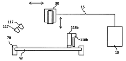
- FIG. 1 is an upper plan view showing an overall configuration of a substrate processing apparatus including a substrate cleaning apparatus according to a first embodiment.
- FIGS. 6A to 6D are front sectional views when the direction changing unit is adopted in the first embodiment
- FIGS. 6E and 6F are direction changing units in the first embodiment.
- the side sectional view of the substrate cleaning device which showed the mode provided with two supply bodies used by a 1st embodiment.
- the upper top view of the supply body which showed the aspect provided with two vibrating bodies used by 1st Embodiment.
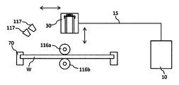
- the side sectional view of the substrate cleaning device showing the mode in which the supply body used in the first embodiment is used together with the roll cleaning member and the nozzle for supplying the cleaning liquid.
- the side sectional view of the substrate cleaning device showing the mode in which the supply body used in the first embodiment is used together with the pencil cleaning member, the two-fluid jet cleaning unit, and the nozzle for supplying the cleaning liquid.
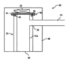
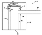
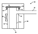
- the sectional side view which showed the aspect 1 of the supply body used by 2nd Embodiment.
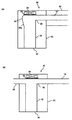
- FIG. 19A is a side sectional view showing a mode using a closing portion that can be used in the first embodiment
- FIG. 19B is a closing portion that can be used in the second embodiment.
- Side sectional drawing which showed the aspect using this.
- the upper top view which shows the whole structure of the substrate processing apparatus containing the substrate cleaning apparatus by 3rd Embodiment.
- the side sectional view of the substrate cleaning device by a 3rd embodiment.
- Side sectional drawing which showed the aspect 1 of the supply body used by 3rd Embodiment.
- the sectional side view which showed the aspect 2 of the supply body used by 3rd Embodiment.
- Side sectional drawing which showed the aspect 3 of the supply body used by 3rd Embodiment.
- cleaning apparatus which showed the aspect in which the supply body used by 3rd Embodiment was used with the nozzle which supplies a roll washing
- the side sectional view of the substrate cleaning device showing the mode in which the supply body used in the third embodiment supplies and uses the pencil cleaning member, the two-fluid jet cleaning unit, and the cleaning liquid.
- Side sectional drawing which showed the supply body used in 4th Embodiment.
- the sectional side view which showed the supply body used in the modification 1 of 4th Embodiment.
- the top view which shows the whole structure of the processing apparatus containing the substrate processing apparatus by 5th Embodiment.
- FIG. 43 (a) is a side view showing an example of the supply pipe, the droplet guide section, and the supply pipe holding section used in the seventh embodiment, and FIG. 43 (b) shows the seventh embodiment.
- maintenance part which are used in FIG. Sectional drawing which looked at the vibration part, guide tube, etc. which are used in 8th Embodiment from upper direction.
- FIG. 1 is a schematic top view of a substrate processing apparatus according to an embodiment.
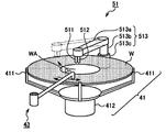
- FIG. The top view which shows a mode that the chuck
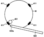
- FIG. The top view which shows a mode that the bevel of the board
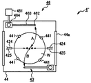
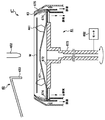
- FIG. 4 is a diagram showing a schematic configuration of a cleaning device 426.
- the substrate processing apparatus has a substantially rectangular housing 110 and a load port 112 on which a substrate cassette for stocking a large number of substrates W is placed.
- the load port 112 is disposed adjacent to the housing 110.
- the load port 112 can be equipped with an open cassette, SMIF (Standard Mechanical Interface) pod, or FOUP (Front Opening Unified Unified Pod).
- SMIF pods and FOUPs are sealed containers that can maintain an environment independent of the external space by accommodating a substrate cassette inside and covering with a partition wall.
- An example of the substrate W is a semiconductor wafer.
- polishing units 114a to 114d Inside the housing 110, a plurality of (four in the embodiment shown in FIG. 1) polishing units 114a to 114d, a first cleaning unit 116 and a second cleaning unit 118 for cleaning the substrate W after polishing, and a post-cleaning unit A drying unit 120 for drying the substrate W is accommodated.
- the polishing units 114a to 114d are arranged along the longitudinal direction of the substrate processing apparatus, and the cleaning units 116 and 118 and the drying unit 120 are also arranged along the longitudinal direction of the substrate processing apparatus.
- an image sensor such as a CMOS (Complementary Metal Oxide Semiconductor) or a CCD (Charge Coupled Device), or a magnetic field in an MRAM (Magnetoresistive Random Access Memory).
- various substrates W can be polished.
- the first transfer robot 122 In the region surrounded by the load port 112, the polishing unit 114a located on the load port 112 side, and the drying unit 120, the first transfer robot 122 is disposed.
- a transport unit 124 is disposed in parallel with the polishing units 114a to 114d, the cleaning units 116 and 118, and the drying unit 120.
- the first transfer robot 122 receives the substrate W before polishing from the load port 112 and transfers it to the transfer unit 124, or receives the dried substrate W taken out from the drying unit 120 from the transfer unit 124.
- a second transfer robot 126 for transferring the substrate W between the first cleaning unit 116 and the second cleaning unit 118 is disposed, and the second cleaning unit.
- a third transfer robot 128 that transfers the substrate W between the second cleaning unit 118 and the drying unit 120 is disposed.
- a control unit 50 that controls the movement of each device of the substrate processing apparatus is disposed inside the housing 110. In the present embodiment, description will be made using an aspect in which the control unit 50 is disposed inside the housing 110, but the present invention is not limited to this, and the control unit 50 may be disposed outside the housing 110.
- the first cleaning unit 116 in the presence of the cleaning liquid, roll cleaning members 116a and 116b extending linearly over almost the entire length of the substrate W are brought into contact with each other, and the substrate W is rotated while rotating around a central axis parallel to the substrate W.
- a roll cleaning device that scrubs the surface may be used (see FIG. 9).
- the second cleaning unit 118 in the presence of the cleaning liquid, the lower end contact surface of the cylindrical pencil cleaning member 118a extending in the vertical direction is brought into contact, and the pencil cleaning member 118a is moved in one direction while rotating.
- a pencil cleaning apparatus for scrub cleaning the surface of the substrate W may be used (see FIG. 10).
- IPA vapor is ejected from the moving spray nozzle toward the horizontally rotating substrate W to dry the substrate W, and the substrate W is rotated at high speed to dry the substrate W by centrifugal force.
- a spin drying unit may be used.
- the first cleaning unit 116 is not a roll cleaning device but a pencil cleaning device similar to the second cleaning unit 118, or a two-fluid jet cleaning device that cleans the surface of the substrate W with a two-fluid jet. May be.
- the second cleaning unit 118 is not a pencil cleaning device, but a roll cleaning device similar to the first cleaning unit 116, or a two-fluid jet cleaning device that cleans the surface of the substrate W with a two-fluid jet. May be.
- the substrate cleaning apparatus according to the embodiment of the present invention can be applied to both the first cleaning unit 116 and the second cleaning unit 118, and can also be used with a roll cleaning apparatus, a pencil cleaning apparatus, and / or a two-fluid jet cleaning apparatus. .
- the supply body 30 (described later) according to the present embodiment is a roll that cleans the first surface (upper surface in FIG. 9) and the second surface (lower surface in FIG. 9) of the substrate W.
- the cleaning members 116a and 116b and the nozzle 117 that supplies the cleaning liquid may be used.
- the supply body 30 according to the present embodiment includes a pencil cleaning member 118 a and a two-fluid jet cleaning unit 118 b that clean the first surface (the upper surface in FIG. 10) of the substrate W. Further, it may be used together with a nozzle 117 for supplying a cleaning liquid.
- the cleaning liquid of this embodiment includes a rinse liquid such as pure water (DIW), ammonia hydrogen peroxide (SC1), hydrochloric acid hydrogen peroxide (SC2), sulfuric acid hydrogen peroxide (SPM), sulfuric acid hydrate, hydrofluoric acid, and the like. Contains chemicals. Unless otherwise specified in the present embodiment, the cleaning liquid means either a rinsing liquid or a chemical liquid.
- DIW pure water
- SC1 ammonia hydrogen peroxide
- SC2 hydrochloric acid hydrogen peroxide
- SPM sulfuric acid hydrogen peroxide
- sulfuric acid hydrate hydrofluoric acid
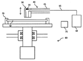
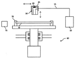
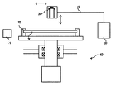
- the substrate cleaning apparatus rotates a substrate support unit 70 such as a chuck that supports (holds) the substrate W, and the substrate W supported by the substrate support unit 70. And a rotating part 60 to be moved.
- the substrate support unit 70 and the rotation unit 60 constitute a substrate rotation mechanism.
- FIGS. 2 and 3 only two substrate support portions 70 are shown. However, when viewed from above, in this embodiment, the four substrate support portions 70 are equally (centered on the rotation center). At an angle of 90 °.
- substrate support parts 70 should just be able to support the board
- a spindle or the like can also be used as the substrate support portion 70 that supports the substrate W.
- the substrate W is supported while being rotated, and the spindle also functions as a rotating part.
- 2 and 3 show an example in which the substrate W is supported in the horizontal direction.
- the present invention is not limited to this.
- the substrate W may be supported in the vertical direction (vertical direction) or in an oblique direction.
- the controller 50 controls the rotation direction and the number of rotations of the substrate W.
- the rotation speed of the substrate W may be constant or variable.
- the supply body 30 is connected to the supply unit 10 via the supply pipe 15.
- the supply body 30 may be held by the swinging unit 40.
- the oscillating portion 40 is connected to a first extending portion 41 extending in a direction orthogonal to the normal line of the substrate W, and a base end side of the first extending portion 41, and extends in the normal direction of the substrate W. And two extending portions 42 (see FIG. 6). Then, the supply body 30 may be connected to the tip end portion of the first extension portion 41.
- the phrase “extended in the normal direction of the substrate W” only needs to extend including the “component in the normal direction of the substrate W”, and is inclined from the “normal direction of the substrate W”. It may be.
- the oscillating portion 40 may be movable along the normal direction (vertical direction in FIG. 2) of the substrate W by an actuator (not shown), for example.
- a supply body holding portion 45 that holds the supply body 30 so as to be movable by sliding, for example, in a plane perpendicular to the normal direction of the substrate W (left and right in FIG. 3 and the front and back direction of the paper surface). It may be provided.
- the supply pipe 15 may have plasticity, and may follow when the supply body 30 moves.
- the supply body holding part 45 may be movable along the normal direction (vertical direction in FIG. 3) of the substrate W by, for example, an actuator (not shown).
- a rotating cup (not shown) that is outside the substrate support portion 70 and covers the periphery of the substrate W and rotates in synchronization with the substrate W may be provided. Good.
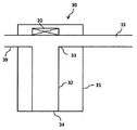
- the substrate cleaning apparatus is provided in the supply body 10, a supply section 10 that supplies a cleaning liquid, a supply body 30 that supplies the cleaning liquid supplied from the supply section 10 to the substrate W, and the supply body 30. And a vibration unit 20 that applies ultrasonic vibration to the cleaning liquid supplied from the supply unit 10.
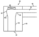
- the supply body 30 includes a main body 31, an outflow port 34 for discharging the cleaning liquid to the substrate W, a guide unit 32 for guiding the cleaning liquid to the outflow port 34, and a supply unit. And an inlet 33 through which the cleaning liquid supplied from 10 flows into the guide portion 32.
- a guide portion 32 is formed by the inner wall of the main body portion 31.
- the guide part 32 has the expansion part 35 into which the cleaning liquid flows after passing through the vibration corresponding position corresponding to the vibration part 20.
- the “vibration corresponding position” in the present embodiment is a position facing the vibration unit 20, and is an area located below the vibration unit 20 when described with reference to FIG. 4.
- the “expanding portion 35” in the present embodiment is a portion that expands outward from the other portions of the guide portion 32, and is, for example, larger than the cross-sectional area of the guide portion 32 at or near the outflow port 34. It means a part having a large cross-sectional area.
- an inflating portion 35 that inflates outward may be provided on the opposite surface facing the inflow port 33.
- the inflating portion 35 may be a surface including the inflow port 33 or may be inflated, and the entire peripheral surface including the surface opposite to the inflow port 33 and the surface including the inflow port 33 is formed. You may be expanding toward the outward side.
- the surface including the inflow port 33 is not expanded, and the surface on the inflow port 33 side may not be expanded.
- the “surface on the inlet 33 side” means a surface located on the inlet 33 side of the center of the guide portion 32 in a plan view (when viewed from the upper side in FIG. 4). .
- the control unit 50 described above may supply the cleaning liquid from the supply unit 10 before supplying the cleaning liquid to the substrate W. Further, instead of or using this mode, the control unit 50 prior to supplying the cleaning liquid to the substrate W, the direction changing unit 55 ( May be controlled (see FIG. 6D). Note that the “direction opposite to the substrate W” only needs to include a component toward the opposite side of the substrate W, and the upper component in FIG. 6D will be described with reference to FIG. It only has to be included.
- the ultrasonic vibration generated by the vibration unit 20 is applied to the cleaning liquid via the guide unit 32 or the closing unit 36 (see FIG. 19A) or directly. 4 and 5, the vibration unit 20 is provided in contact with the guide unit 32, and the ultrasonic vibration generated by the vibration unit 20 is applied to the cleaning liquid via the guide unit 32. ing.
- the vibration part 20 is provided in contact with the closing part 36, and the ultrasonic vibration generated by the vibration part 20 is applied to the cleaning liquid via the closing part 36. It has become.
- the material of the guide portion 32 for example, quartz, stainless steel, sapphire, PTFE, PEEK, carbon-containing resin, or the like can be used.
- quartz and sapphire are materials that are less likely to attenuate ultrasonic vibration. For this reason, by using such quartz or sapphire, it is possible to prevent the ultrasonic vibration applied to the cleaning liquid from being attenuated.
- the closing portion 36 may be formed of a material including Ta, quartz, PTFE, PEEK, carbon-containing resin (C-PTFE, C-PEEK, etc.) or sapphire. , Ta, quartz, PTFE, PEEK, carbon-containing resin (C-PTFE, C-PEEK, etc.) or sapphire.
- the guide portion 32 is made of a resin material and the flow rate of the cleaning liquid flowing in the guide portion 32 is increased, charging may be caused due to contact between the cleaning liquid and the guide portion 32. is there. Then, when the tip of the guide part 32 in which such charging has occurred is brought close to the substrate W, the surface of the substrate W may be charged through the space due to the influence of charging in the guide part 32. Therefore, a carbon-containing resin (conductive resin material) such as C-PTFE or C-PEEK is adopted as the resin material of the guide portion 32, and the guide portion 32 is connected to the ground via the swinging portion 40 or the like. It is beneficial.
- a sealing member such as an O-ring may be provided between the closing portion 36 and the outer surface (main body portion 31) of the wall surface that constitutes the guide portion 32.
- a sealing member such as an O-ring larger than the opening may be provided, and this sealing member may be sandwiched between the closing portion 36 and the outer surface (main body portion 31) of the wall surface constituting the guide portion 32.
- a direction changing unit 55 that can change the angle of the outlet 34 may be provided.
- the direction changing unit 55 may tilt the supply body 30 with respect to the substrate W so that the angle of the outlet 34 with respect to the substrate W can be freely changed. (See FIGS. 6B to 6D).
- the outlet 34 may be directed toward the center of the substrate W, or the outlet 34 is directed toward the peripheral edge of the substrate W. You may be able to.
- the supply body 30 when it is desired to store the cleaning liquid on the substrate W, the supply body 30 may be inclined with respect to the substrate W at an angle that supplies the cleaning liquid in the direction opposite to the rotation direction of the substrate W.
- the supply body 30 when it is desired to supply the cleaning liquid onto the substrate W without applying resistance, the supply body 30 may be inclined with respect to the substrate W at an angle such that the cleaning liquid is supplied along the rotation direction of the substrate W.
- the angle of the supply body 30 with respect to the substrate W may be changed manually, or may be automatically changed in response to a signal from the control unit 50. When the signal is automatically changed in response to a signal from the control unit 50, the angle at which the supply body 30 is held may be sequentially changed according to the recipe.
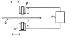
- two or more supply bodies 30 may be provided to supply the cleaning liquid to both the front surface and the back surface of the substrate W.
- the swinging section 40 may be employed as shown in FIG. 2, or the supply body holding section 45 may be employed as shown in FIG. Good. This is the same in other aspects.
- the swinging portion 40 may be employed as shown in FIG. 2, or as shown in FIG.
- the supply body holding part 45 may be employed. 4 to 6 show an embodiment using the swinging unit 40, this is merely an example, and a supply body holding unit 45 as shown in FIG. 3 may be used.
- the controller 50 causes the moving speed of the supply body 30 to be slower when the supply body 30 cleans the peripheral side region of the substrate W than when the supply body 30 cleans the central side region of the substrate W. You may control.
- the “center side region” in the present embodiment is used in comparison with the “peripheral side region” and means a region located on the center side of the substrate W compared with the “peripheral side region”. . .
- control unit 50 may start the vibration of the vibration unit 20 after the first time has elapsed after the cleaning liquid is supplied from the supply unit 10. Further, the control unit 50 may start supplying the cleaning liquid from the outlet 34 to the substrate W after a lapse of a second time longer than the first time after the cleaning liquid is supplied from the supply unit 10. At this time, the cleaning liquid is continuously supplied after the first time has elapsed since the supply of the cleaning liquid from the supply unit 10, and the supply body 30 moves after the third time that is longer than the first time and shorter than the second time. The cleaning liquid may be supplied to the peripheral portion of the substrate W after the second time has elapsed since the cleaning liquid was supplied from the supply unit 10.
- the cleaning liquid is continuously supplied from the peripheral portion of the substrate W toward the central portion.
- the supply of the cleaning liquid from the supply unit 10 is stopped while the outflow port 34 moves from the peripheral portion of the substrate W to above the central portion, and the outflow port 34 is above the central portion of the substrate W.
- the cleaning liquid may be discharged again from the outlet 34 and supplied to the central portion of the substrate W.
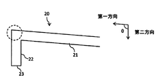
- the second extending portion 22 may move from the central portion of the substrate W toward the peripheral portion, and conversely, the second extending portion 22 is moved from the peripheral portion of the substrate W. It may move toward the center, or such movement may be repeated.
- ultrasonic vibration when supplying the cleaning liquid to the substrate W, ultrasonic vibration is not always applied to the cleaning liquid.
- the flow is performed before supplying the cleaning liquid to the substrate W without performing ultrasonic vibration.
- the cleaning liquid may be discharged from the outlet 34.
- the substrate cleaning apparatus may further include a discharge liquid recovery unit 75 for recovering the cleaning liquid discharged from the outlet 34 at the standby position.
- the discharge liquid recovery unit 75 is connected to a drainage recovery unit (not shown), and the recovered cleaning liquid may be drained.
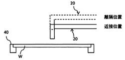
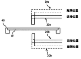
- the supply body 30 is positioned at the close position when supplying the cleaning liquid to the substrate W, and the supply body 30 is set at the separated position when the cleaning liquid is not supplied to the substrate W, as indicated by the double arrows in the vertical direction in FIGS. It may be positioned.
- the “separated position” means a position far from the substrate W in the normal direction of the substrate W compared to the “close position”, and conversely, the “close position” is compared with the “separated position”. This means a position close to the substrate W in the normal direction of the substrate W.
- the supply body 30 is connected to an actuator (not shown), and may be positioned at a close position and a remote position by the actuator.
- the substrate support unit 70 may be movable in the vertical direction, and the substrate W may take a “separation position” and a “proximity position” with respect to the supply body 30, or the supply body 30 and the substrate support section 70. Both of them can move in the vertical direction, and the “separation position” and the “proximity position” may be obtained by appropriately positioning both the substrate W and the supply body 30.
- the guide portion 32 is made of a material that hardly attenuates ultrasonic vibrations, such as quartz, and adopts a mode in which the supply body 30 is positioned in the proximity position prior to supplying the cleaning liquid to the substrate W.
- the cleaning liquid can be supplied to the substrate W by being guided to the position close to the substrate W by the guide portion 32 made of a material that hardly attenuates the ultrasonic vibration.
- the supply body 30 may be positioned at the separation position. By positioning the supply body 30 in the separated position in this way, it is possible to prevent the cleaning liquid or other liquids from adhering to the supply body 30, the first extending portion 41, or the supply pipe 15 in an unexpected manner.
- the supply body 30 may be positioned at the standby position. And the supply body 30 may be located in a separation position in this standby position.
- the standby position means, for example, a position where the supply body 30 is not positioned in the normal direction of the substrate W. In the aspect in which the substrate W is arranged to extend along the horizontal direction, It means that the supply body 30 is not located.
- the standby position a position where the cleaning liquid can be discharged to the discharge liquid recovery unit 75 described above can be given.
- the cleaning liquid Prior to supplying the cleaning liquid to the substrate W, when the cleaning liquid is supplied from the supply unit 10 and discharged from the outlet 34 at the standby position toward the discharge liquid recovery unit 75, for example, the cleaning liquid is positioned in the proximity position. May be. Positioning at the close position in this way can prevent the discharged cleaning liquid from being inadvertently scattered.
- the supply body 30 may be positioned at the separation position (upper position) at the standby position, and may be moved above the substrate W after being positioned at the proximity position (lower position) at the standby position. By being positioned at the separation position in the standby position in this manner, it is possible to more reliably prevent the cleaning liquid and other liquids from adhering to the supply body 30 in an unexpected manner. Further, when the supply body 30 moves on the substrate W by being moved after being positioned at the proximity position (lower position) in the standby position, the cleaning liquid can be supplied at a position close to the substrate W. Can be efficiently cleaned.
- the supply body 30 is positioned at the separation position (upper position) in the standby position, moved in the state above the substrate W, and after the outlet 34 is positioned at the center of the substrate W, the supply body 30 approaches. It may be positioned at a position (downward position). According to such an aspect, when the supply body 30 moves over the substrate W, it can be expected to prevent the cleaning liquid or other liquids from the previous step from adhering to the supply body 30.
- the supply body 30 has the expansion part 35 into which the cleaning liquid flows after passing through the vibration corresponding position corresponding to the vibration part 20. For this reason, the cleaning liquid supplied from the supply unit 10 can pass through the vibration corresponding position efficiently. Therefore, it is possible to efficiently prevent the occurrence of a state in which the vibration unit 20 vibrates in a state where there is no cleaning liquid (a so-called emptying state).
- the inflow portion 35 is introduced from the inflow port 33. It is possible to smoothly pass the cleaning liquid through the vibration corresponding position. For this reason, it can prevent more efficiently beforehand that the state where the vibration part 20 vibrates in the state where the cleaning liquid does not exist is generated. Further, by adopting this mode, it is possible to efficiently form convection of the cleaning liquid flowing in from the inlet 33 in the expansion portion 35. For this reason, the state in which no cleaning liquid is present can be solved more efficiently.
- the cleaning liquid can be poured into the guide portion 32 while suppressing the diffusion of the cleaning liquid flowing in from the inlet 33. it can. For this reason, it is possible to smoothly pass the cleaning liquid flowing in from the inlet 33 through the vibration corresponding position. As a result, it is possible to more efficiently prevent the vibration unit 20 from vibrating in the absence of the cleaning liquid.
- the expanding portion 35 may have a tapered shape 35 a facing the outlet 34.
- the cleaning liquid that has flowed into the expansion portion 35 from the inflow port 33 can be efficiently convected by the expansion portion 35 and then directed toward the outflow port 34. For this reason, the space in which no cleaning liquid is present can be eliminated more efficiently.
- the cleaning liquid Prior to supplying the cleaning liquid to the substrate W, when the cleaning liquid is supplied from the supply unit 10 and, for example, the cleaning liquid is discharged from the outlet 34 at the standby position, oxygen or the like enters and the cleaning effect is increased.
- a low cleaning solution can be discharged, and ultrasonic cleaning can be applied to the cleaning solution having a high cleaning effect containing nitrogen or the like, and used for cleaning the substrate W.
- the substrate W can be cleaned with a cleaning liquid that is sufficiently supplied with ultrasonic waves and has a high cleaning effect, rather than a cleaning liquid that is not sufficiently applied with ultrasonic waves and does not have a high cleaning effect.
- the substrate W when the substrate W is cleaned with a cleaning liquid that contains oxygen or the like and is not sufficiently supplied with ultrasonic waves, there is a possibility that a malfunction may occur. Can be prevented from occurring. Further, the substrate W can be cleaned with a cleaning solution having a uniform cleaning power from the start of the cleaning of the substrate W, and stable substrate cleaning can be realized.
- the mode in which the moving speed of the supply body 30 becomes slower when the outlet 34 cleans the peripheral side region of the substrate W than when the outlet 34 cleans the central region of the substrate W is adopted.
- the amount of the cleaning liquid supplied per unit area of W can be made close to a uniform one.
- the moving speed of the supply body 30 may be calculated based on the 2 ⁇ r, and the supply body 30 may be moved based on the moving speed. Instead of such a mode, the moving speed of the supply body 30 is simply or intermittently decreased while moving from the center of the substrate W toward the periphery, and conversely, from the periphery of the substrate W. While moving toward the center, the moving speed of the supply body 30 may be increased continuously or intermittently. Such an aspect is advantageous in that the control is not complicated.
- the vibration unit 20 When adopting a mode in which the vibration of the vibration unit 20 is started after the first time has elapsed since the cleaning liquid is supplied from the supply unit 10, the vibration unit 20 is vibrated after flowing the cleaning liquid, so that the cleaning liquid is not present ( It can prevent more reliably that the vibration part 20 vibrates in a so-called empty state) and the vibration part 20 is damaged.
- the first time is, for example, about 0.1 seconds to 1 second. Regarding the first time, it is only necessary to prevent a state in which the cleaning liquid is not present in the portion facing the vibration unit 20, and therefore it is not necessary to take a long time.
- the vibration section 20 need not be vibrated.
- the inside of the guide part 32 is previously cleaned with the cleaning liquid to which the ultrasonic vibration is applied by vibrating the vibration part 20 in advance. It is beneficial in that it can.
- sufficient ultrasonic vibration can be given in advance to the cleaning liquid in the guide portion 32 (sufficient energy can be stored), and when cleaning the substrate W from the beginning. A cleaning solution having a sufficiently high cleaning power can be supplied.
- 2nd time is time when all the washing
- the discharge liquid recovery unit 75 for recovering the cleaning liquid discharged from the outlet 34 at the standby position When a mode in which the discharge liquid recovery unit 75 for recovering the cleaning liquid discharged from the outlet 34 at the standby position is employed, the discharged cleaning liquid that is not used for cleaning can be reliably recovered. . For this reason, it is possible to reduce the possibility that the cleaning liquid discharged from the outlet 34 will bounce back to become mist and adversely affect the substrate W.
- the substrate cleaning apparatus of this embodiment is incorporated in a two-fluid jet cleaning apparatus that cleans the surface of the substrate W with two fluids in which a liquid and a gas are mixed (see FIG. 10), for example, a two-fluid jet cleaning process
- the substrate W may be cleaned by the supply body 30 of the present embodiment.
- the two-fluid jet cleaning can be performed after the particles attached to the substrate W are floated by the cavitation effect of the cleaning liquid to which ultrasonic waves are applied.
- the cavitation effect is a cleaning effect using a shock wave generated by the burst of bubbles generated in the cleaning liquid by ultrasonic waves.
- the modified vibration unit 20 may be configured to vibrate at a first frequency and a second frequency lower than the first frequency to give ultrasonic vibration to the cleaning liquid.
- an ultrasonic vibration may be applied to the cleaning liquid at three or more frequencies.
- ultrasonic vibration can be applied to the cleaning liquid at different frequencies. For this reason, the cleaning power by the cleaning liquid can be changed according to the application.
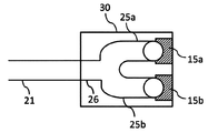
- the vibration part 20 may vibrate at a different frequency, as shown in FIG. 8, the vibration part 20 has a first vibration part 20a that vibrates at a first frequency and a second frequency lower than the first frequency. You may have the 2nd vibration part 20b vibrated by. According to such an aspect, it is advantageous in that ultrasonic vibrations having different frequencies can be given with a simple configuration.
- the first vibration unit 20a may be electrically connected to a first transmitter 21a that sends a signal to the first vibration unit 20a.
- the 2nd vibration part 20b may be electrically connected with the 2nd transmitter 21b which sends a signal to this 2nd vibration part 20b.
- the supply body 30 includes a first supply body 30a and a second supply body 30b held by the casing 30 ′. And the 1st supply body 30a has the 1st vibration part 20a connected to the 1st transmitter 21a, and the 2nd supply body 30b has the 2nd vibration part 20b connected to the 2nd transmitter 21b. Yes.
- the first supply body 30a and the second supply body 30b move as the casing 30 ′ moves, but the first supply body 30a and the second supply body 30b are separated. It may be a mode of moving to.
- the first frequency may be 900 kHz or more and 5 MHz or less
- the second frequency may be less than 900 kHz.
- the vibration width is small, so that relatively small impurities can be removed, and the effect of cavitation is reduced, so that the load applied to the substrate W can be reduced.
- the vibration width is large, so that relatively large impurities can be removed.
- the difference between the first frequency and the second frequency is small, the difference in effect is also small. For this reason, as an example, the difference between the first frequency and the second frequency may be about 500 kHz.
- 950 kHz may be used as the first frequency and 430 kHz may be used as the second frequency.
- 950 kHz can be used as a 1st frequency and 750 kHz can be used as a 2nd frequency.
- the substrate W is cleaned using the pencil cleaning member 118a, (1) the substrate W is then cleaned by applying ultrasonic vibration to the cleaning liquid at the second frequency, and (3) Thereafter, the substrate W may be cleaned by applying ultrasonic vibration to the cleaning liquid at the first frequency.
- the load applied to the pencil cleaning member 118a can be reduced as compared with the conventional case, and the life of the pencil cleaning member 118a can be extended.
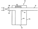
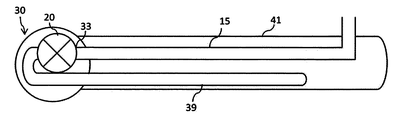
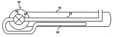
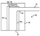
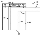
- a guide tube 39 into which the cleaning liquid after passing through the vibration corresponding position corresponding to the vibration unit 20 flows is provided.
- the guide tube 39 may be provided with an opening / closing part 38 such as a valve.
- the opening / closing unit 38 may be configured to open / close in response to a command from the control unit 50.
- the opening / closing part 38 is opened before supplying the cleaning liquid from the supply part 10, and after a certain time (for example, 1 second to several seconds) elapses, the opening / closing part 38. May be closed.
- the cleaning liquid that has passed through the guide tube 39 may be recovered by the discharge liquid recovery unit 75 (see FIGS. 2 and 3).
- At least a part of the guide tube 39 may extend within the first extending portion 41 (see FIGS. 15 to 18).
- the cleaning liquid supplied from the supply unit 10 can be efficiently passed through the vibration corresponding position as in the first embodiment. Therefore, it is possible to efficiently prevent the occurrence of a state in which the vibration unit 20 vibrates in a state where there is no cleaning liquid (a so-called emptying state).
- the guide tube 39 may be provided at a position facing the inflow port 33. That is, the guide tube 39 may be provided at a position facing the inflow port 33.
- the cleaning liquid flowing into the guide portion 32 from the inlet 33 can be smoothly guided to the guide tube 39.
- the upper ends of the supply pipe 15 and the guide pipe 39 may be provided so as to coincide with the upper ends of the guide portions 32.
- the cleaning liquid flowing in from the supply pipe 15 can be smoothly poured into the guide pipe 39 at the vibration corresponding position corresponding to the vibration unit 20. For this reason, it is possible to more efficiently prevent a state in which the vibration unit 20 vibrates in a state where there is no cleaning liquid (so-called airing state).
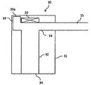
- the guide tube 39 may extend in parallel with the direction in which the supply tube 15 extends, but may be bent as shown in FIG. 12.
- the guide tube 39 is bent toward the side opposite to the substrate W (upper side in FIG. 12).
- the guide tube 39 may be bent toward the substrate W side, or the guide tube 39 may be bent in a direction parallel to the surface direction of the substrate W.
- the guide tube 39 may have a terminal portion 39a so that the cleaning liquid that has flowed into the guide tube 39 does not flow outward. Note that when the guide tube 39 is bent upward in the form having the end portion 39a, it can be expected that outside air such as air accumulates in the end portion 39a, and the vibration corresponding to the vibration portion 20 is obtained. This is advantageous in that outside air such as air hardly accumulates at the corresponding position.
- the supply part is made by closing the opening / closing part 38 when supplying the cleaning liquid to the substrate W.
- This is advantageous in that all or almost all of the cleaning liquid supplied from 10 can be supplied to the substrate W.
- the opening / closing portion 38 is opened so that the cleaning liquid flowing into the guide tube 39 can flow smoothly, and there is external air such as air at the vibration corresponding position.
- it is beneficial in that it can be washed away smoothly.
- the arrangement of the supply pipe 15 and the guide pipe 39 can be freely changed.
- the guide pipe 39 may be embedded in the supply body 10 as shown in FIG. 16, or as shown in FIGS. Further, a part of the guide tube 39 may be exposed to the outside of the supply body 10, or a part of the supply tube 15 and the guide tube 39 may be exposed to the outside as shown in FIG.
- the closing part 36 may be used.
- the position of the guide portion 32 that faces the closing portion 36 is open, and the opening is completely covered by the closing portion 36. It will be.
- a bevel cleaning device that cleans the bevel portion of the substrate W, or spin drying mounted on a plating device. It can also be used for (SRD) devices.
- the substrate cleaning apparatus is: A supply unit for supplying a cleaning liquid; A supply body for supplying the substrate with the cleaning liquid supplied from the supply unit; A vibration unit that is provided in the supply body and applies ultrasonic vibration to the cleaning liquid supplied from the supply unit; With The supply body has an expansion part into which the cleaning liquid flows after passing through a vibration corresponding position corresponding to the vibration part.
- the supply body includes an outlet for discharging the cleaning liquid to the substrate, a guide part for guiding the cleaning liquid to the outlet, and an inlet for allowing the cleaning liquid supplied from the supply part to flow into the guide part.
- the inflating part may inflate at least on the opposite surface facing the inflow port.
- the supply body includes an outlet for discharging the cleaning liquid to the substrate, a guide part for guiding the cleaning liquid to the outlet, and an inlet for allowing the cleaning liquid supplied from the supply part to flow into the guide part.
- the substrate cleaning apparatus is A supply unit for supplying a cleaning liquid; A supply body for supplying the substrate with the cleaning liquid supplied from the supply unit; A vibration unit that is provided in the supply body and applies ultrasonic vibration to the cleaning liquid supplied from the supply unit; And a guide tube into which the cleaning liquid after passing through the vibration corresponding position corresponding to the vibration part flows.
- the substrate cleaning apparatus is You may further provide the discharge liquid collection
- the substrate cleaning apparatus is A first extending portion that supports the supply body and that can swing around the base side; At least a portion of the guide tube may extend within the first extension.
- the apparatus may further include a control unit that supplies the cleaning liquid from the supply unit.
- the control unit may start the vibration of the vibration unit after a first time has elapsed since the cleaning liquid was supplied from the supply unit.
- Substrate cleaning equipment The supply body has an outlet for flowing out the cleaning liquid, You may further provide the direction change part which orient
- the supply body includes an outlet for discharging the cleaning liquid to the substrate, a guide part for guiding the cleaning liquid to the outlet, and an inlet for allowing the cleaning liquid supplied from the supply part to flow into the guide part.
- the guide portion may be made of a conductive resin material and connected to ground.
- the supply body of the present embodiment is provided with an expansion portion or a guide tube into which the cleaning liquid flows after passing through the vibration corresponding position corresponding to the vibration portion. For this reason, the cleaning liquid supplied from the supply unit can be efficiently passed through the vibration corresponding position. Therefore, it is possible to efficiently prevent the occurrence of a state in which the vibration part vibrates in a state where there is no cleaning liquid (so-called emptying state).
- the third and fourth embodiments have been made in view of such points, and fine dust or the like is generated when supplying a cleaning liquid to which ultrasonic vibration is applied to a substrate such as a semiconductor wafer.
- An object of the present invention is to provide a substrate cleaning apparatus and a substrate processing apparatus that can prevent this.
- a reference numeral of the drawing is newly added in addition to the reference numeral of the preceding drawing.
- FIG. 20 to FIG. 33 are diagrams for explaining an embodiment of the present invention.
- the substrate processing apparatus has a substantially rectangular housing 110 and a load port 112 on which a substrate cassette for stocking a large number of substrates W is placed.
- the load port 112 is disposed adjacent to the housing 110.
- the load port 112 can be equipped with an open cassette, SMIF (Standard Mechanical Interface) pod, or FOUP (Front Opening Unified Unified Pod).
- SMIF pods and FOUPs are sealed containers that can maintain an environment independent of the external space by accommodating a substrate cassette inside and covering with a partition wall.
- An example of the substrate W is a semiconductor wafer.
- polishing units 114a to 114d Inside the housing 110, a plurality of (four in the embodiment shown in FIG. 20) polishing units 114a to 114d, a first cleaning unit 116 and a second cleaning unit 118 for cleaning the polished substrate W, and a post-cleaning unit A drying unit 120 for drying the substrate W is accommodated.
- the polishing units 114a to 114d are arranged along the longitudinal direction of the substrate processing apparatus, and the cleaning units 116 and 118 and the drying unit 120 are also arranged along the longitudinal direction of the substrate processing apparatus.
- an image sensor such as a CMOS (Complementary Metal Oxide Semiconductor) or a CCD (Charge Coupled Device), or a magnetic field in an MRAM (Magnetoresistive Random Access Memory).
- CMOS Complementary Metal Oxide Semiconductor
- CCD Charge Coupled Device
- MRAM Magnetic Random Access Memory
- the first transfer robot 122 In the region surrounded by the load port 112, the polishing unit 114a located on the load port 112 side, and the drying unit 120, the first transfer robot 122 is disposed.
- a transport unit 124 is disposed in parallel with the polishing units 114a to 114d, the cleaning units 116 and 118, and the drying unit 120.
- the first transfer robot 122 receives the substrate W before polishing from the load port 112 and transfers it to the transfer unit 124, or receives the dried substrate W taken out from the drying unit 120 from the transfer unit 124.
- a second transfer robot 126 for transferring the substrate W between the first cleaning unit 116 and the second cleaning unit 118 is disposed, and the second cleaning unit.
- a third transfer robot 128 that transfers the substrate W between the second cleaning unit 118 and the drying unit 120 is disposed.
- a control unit 50 that controls the movement of each device of the substrate processing apparatus is disposed inside the housing 110. In the present embodiment, description will be made using an aspect in which the control unit 50 is disposed inside the housing 110, but the present invention is not limited to this, and the control unit 50 may be disposed outside the housing 110.
- the first cleaning unit 116 in the presence of the cleaning liquid, roll cleaning members 116a and 116b extending linearly over almost the entire length of the substrate W are brought into contact with each other, and the substrate W is rotated while rotating around a central axis parallel to the substrate W.
- a roll cleaning device that scrubs the surface may be used (see FIG. 32).
- the second cleaning unit 118 in the presence of the cleaning liquid, the lower end contact surface of the cylindrical pencil cleaning member 118a extending in the vertical direction is brought into contact, and the pencil cleaning member 118a is moved in one direction while rotating.
- a pencil cleaning apparatus for scrub cleaning the surface of the substrate W may be used (see FIG. 33).
- IPA vapor is ejected from the moving spray nozzle toward the horizontally rotating substrate W to dry the substrate W, and the substrate W is rotated at high speed to dry the substrate W by centrifugal force.
- a spin drying unit may be used.
- the first cleaning unit 116 is not a roll cleaning device but a pencil cleaning device similar to the second cleaning unit 118, or a two-fluid jet cleaning device that cleans the surface of the substrate W with a two-fluid jet. May be.
- the second cleaning unit 118 is not a pencil cleaning device, but a roll cleaning device similar to the first cleaning unit 116, or a two-fluid jet cleaning device that cleans the surface of the substrate W with a two-fluid jet. May be.
- the substrate cleaning apparatus according to the embodiment of the present invention can be applied to both the first cleaning unit 116 and the second cleaning unit 118, and can also be used with a roll cleaning apparatus, a pencil cleaning apparatus, and / or a two-fluid jet cleaning apparatus. .
- a supply body 30 (described later) according to the present embodiment is a roll that cleans the first surface (upper surface in FIG. 32) and the second surface (lower surface in FIG. 32) of the substrate W.
- the cleaning members 116a and 116b and the nozzle 117 that supplies the cleaning liquid may be used.
- the supply body 30 according to the present embodiment includes a pencil cleaning member 118a and a two-fluid jet cleaning unit 118b for cleaning the first surface (the upper surface in FIG. 33) of the substrate W. Further, it may be used together with a nozzle 117 for supplying a cleaning liquid.
- the cleaning liquid of this embodiment includes a rinse liquid such as pure water (DIW), ammonia hydrogen peroxide (SC1), hydrochloric acid hydrogen peroxide (SC2), sulfuric acid hydrogen peroxide (SPM), sulfuric acid hydrate, hydrofluoric acid, and the like. Contains chemicals. Unless otherwise specified in the present embodiment, the cleaning liquid means either a rinsing liquid or a chemical liquid.
- DIW pure water
- SC1 ammonia hydrogen peroxide
- SC2 hydrochloric acid hydrogen peroxide
- SPM sulfuric acid hydrogen peroxide
- sulfuric acid hydrate hydrofluoric acid
- the substrate cleaning apparatus includes a substrate support unit 70 such as a chuck that supports (holds) the substrate W, and a rotating unit that rotates the substrate W supported by the substrate support unit 70. 60.
- the substrate support unit 70 and the rotation unit 60 constitute a substrate rotation mechanism.
- only two substrate support portions 70 are shown.
- the four substrate support portions 70 are equally (90 ° centered on the rotation center). Arranged at an angle). Note that the number of substrate support portions may be three as long as it can stably support the substrate W, for example.
- a spindle or the like can also be used as the substrate support portion 70 that supports the substrate W.
- the substrate W is supported while being rotated, and the spindle also functions as a rotating part.
- substrate W in the horizontal direction was shown in FIG. 21, it is not limited to this, For example, it is good also as a structure which supports the board
- the controller 50 controls the rotation direction and the number of rotations of the substrate W.
- the rotation speed of the substrate W may be constant or variable.
- a rotating cup (not shown) that is outside the substrate support portion 70 and covers the periphery of the substrate W and rotates in synchronization with the substrate W may be provided. Good.
- the substrate cleaning apparatus has a supply unit 10 for supplying a cleaning liquid.
- the substrate cleaning apparatus includes a vibration unit 20 that applies ultrasonic vibration to the cleaning liquid supplied from the supply unit 10, and the cleaning liquid supplied from the supply unit 10 from the outlet 34 to the substrate W.
- a supply body 30 is also provided.
- the supply body 30 shown in FIGS. 22 to 28 has a main body 48, an inlet 33 into which the cleaning liquid supplied from the supply section 10 flows, and the cleaning liquid flowing in from the inlet 33 flows through the first guide path 31a.
- a first guide portion 31 that guides to the outlet 34 and has an opening 35 that is different from the inlet 33 and the outlet 34 (located at the upper end in FIGS. 22 to 28), and a first guide path 31a.
- a seal portion 45 made of an O-ring or the like provided on the outer periphery of at least a part of the first guide portion 31, and a closing portion 40 that covers the opening portion 35 and contacts the seal portion 45. ing.
- the supply body 30 is connected to the supply unit 10 via the supply pipe 15 (specifically, the opening of the supply body 30 and the supply pipe 15 are connected to each other).
- the detailed configuration of these connecting portions is omitted in FIG.
- the supply pipe 15 may have plasticity, and may follow when the supply body 30 moves as will be described later.
- the closing portion 40 may be formed of a material including Ta, quartz, PFA (polytetrafluoroethylene) or sapphire, and more specifically, the closing portion 40 is formed of Ta, quartz, PFA or sapphire. Also good.
- the ultrasonic vibration generated by the vibration part 20 is applied to the cleaning liquid via the closing part 40 and / or the first guide part 31. 22 to 27, the vibration part 20 is provided in contact with the closing part 40, and the ultrasonic vibration generated by the vibration part 20 is applied to the cleaning liquid via the closing part 40. ing.
- the vibration unit 20 is provided in contact with the first guide portion 31, and the ultrasonic vibration generated by the vibration portion 20 is generated by the first guide portion 31. It may be applied to the cleaning liquid via From the viewpoint of efficiently transmitting ultrasonic vibrations with the cleaning liquid, it is more advantageous that the vibration part 20 is provided adjacent to the closing part 40, and in particular, the vibration part 20 is adjacent to the closing part 40.
- the closure 40 is made of quartz or sapphire.
- the closing portion 40 may have a first protruding portion 41 that protrudes toward the substrate W side (the lower side in FIG. 22) outside the periphery of the first guide portion 31.
- sticker part 45 may be clamped between the edge part and the main-body part 48.
- the main body 48 has a clamping member 49, and the seal portion 45 is clamped between the end of the first projecting portion 41 and the clamping member 49. May be.
- the first guide portion 31 may have a notch 36 at the end opposite to the substrate W (the lower side in FIG. 22).
- the seal portion 45 is located in the notch 36, and the seal portion 45 is provided on the outer periphery of at least a part of the first guide path 31a via the first guide portion 31.
- the closing portion 40 may cover the entire cutout 36 as shown in FIG. 23, or the closing portion 40 may cover a part of the cutout 36 as shown in FIG.
- the first guide portion 31 may have a recess 37 at the end opposite to the substrate W. In this case, even if the seal part 45 is located in the recessed part 37 and the seal part 45 is provided through the first guide part 31 at the outer periphery of at least a part of the first guide path 31a. Good.
- the closing portion 40 is provided on the end surface (the upper end surface in FIG. 25) of the first guide portion 31, and the first protruding portion 41 protruding outward from the peripheral edge of the first guide portion 31 is provided.
- the closing portion 40 may have a first protruding portion 41 that protrudes outward from the peripheral edge of the first guide portion 31 as shown in FIG.
- the first guide portion 31 may have a concave portion 37 on the side surface opposite to the substrate W.
- the closing portion 40 has a first protrusion 41 that protrudes toward the substrate W on the outer periphery of the first guide portion 31, and the seal portion 45 is positioned on the inner periphery of the first protrusion 41.
- the “opposite side surface” means the opposite side of the substrate W from the inflow port 33 (the upper side in FIG. 27), and in a mode in which the inflow port 33 is not provided on the side surface, the first guide portion 31. Means the opposite side of the substrate W from the center in the longitudinal direction (upper side in FIG. 27).
- quartz, stainless steel, sapphire, PFA, or the like can be used as the material of the first guide portion 31.
- quartz and sapphire are materials that are less likely to attenuate ultrasonic vibration. For this reason, by using such quartz or sapphire, it is possible to prevent the ultrasonic vibration applied to the cleaning liquid from being attenuated.
- the supply body 30 can be inclined with respect to the substrate W, and the angle of the outlet 34 with respect to the substrate W may be freely changed.
- the supply body 30 may be inclined with respect to the substrate W at an angle that supplies the cleaning liquid in the direction opposite to the rotation direction of the substrate W.
- the supply body 30 may be inclined with respect to the substrate W at an angle such that the cleaning liquid is supplied along the rotation direction of the substrate W.
- the angle of the supply body 30 with respect to the substrate W may be changed manually, or may be automatically changed in response to a signal from the control unit 50. When the signal is automatically changed in response to a signal from the control unit 50, the angle at which the supply body 30 is held may be sequentially changed according to the recipe.
- two or more supply bodies 30 may be provided, and the cleaning liquid may be supplied to both the front surface and the back surface of the substrate W.
- the “center side region” in the present embodiment is used in comparison with the “peripheral side region” and means a region located on the center side of the substrate W compared with the “peripheral side region”. .
- control unit 50 may start the vibration of the vibration unit 20 after the first time has elapsed after the cleaning liquid is supplied from the supply unit 10. Further, the control unit 50 may start supplying the cleaning liquid from the outlet 34 to the substrate W after a lapse of a second time longer than the first time after the cleaning liquid is supplied from the supply unit 10. At this time, the cleaning liquid is continuously supplied after the first time has elapsed since the supply of the cleaning liquid from the supply unit 10, and the supply body 30 moves after the third time that is longer than the first time and shorter than the second time. The cleaning liquid may be supplied to the peripheral portion of the substrate W after the second time has elapsed since the cleaning liquid was supplied from the supply unit 10.
- the cleaning liquid is continuously supplied from the peripheral portion of the substrate W toward the central portion.
- the supply of the cleaning liquid from the supply unit 10 is stopped while the outflow port 34 moves from the peripheral portion of the substrate W to above the central portion, and the outflow port 34 is above the central portion of the substrate W.
- the cleaning liquid may be discharged again from the outlet 34 and supplied to the central portion of the substrate W.
- the second extending portion 22 may move from the central portion of the substrate W toward the peripheral portion, and conversely, the second extending portion 22 is moved from the peripheral portion of the substrate W. It may move toward the center, or such movement may be repeated.
- ultrasonic vibration when supplying the cleaning liquid to the substrate W, ultrasonic vibration is not always applied to the cleaning liquid.
- the flow is performed before supplying the cleaning liquid to the substrate W without performing ultrasonic vibration.
- the cleaning liquid may be discharged from the outlet 34.
- the substrate cleaning apparatus further includes a discharge liquid recovery unit 75 for recovering the cleaning liquid discharged from the outlet 34 at the standby position when the supply body 30 is at the standby position. Also good. Then, the cleaning liquid discharged downward from the outlet 34 of the supply body is supplied to the opening provided in the upper part of the discharge liquid recovery unit 75 and recovered.
- the discharge liquid recovery part 75 is connected to a drainage recovery part (not shown), and the cleaning liquid recovered by the discharge liquid recovery part 75 is supplied to the drainage recovery part and subjected to a drainage process.
- the supply body 30 can move not only in the surface direction of the substrate W (left-right direction in FIG. 21) but also in the normal direction of the substrate W (up-down direction in FIG. 21). Good. In this case, the supply body 30 may be positioned at a close position when supplying the cleaning liquid to the substrate W, and the supply body 30 may be positioned at a remote position when the cleaning liquid is not supplied to the substrate W.
- the “separated position” means a position far from the substrate W in the normal direction of the substrate W compared to the “close position”, and conversely, the “close position” is compared with the “separated position”. This means a position close to the substrate W in the normal direction of the substrate W.
- the supply body 30 is connected to an actuator (not shown), and may be positioned at a close position and a remote position by the actuator.
- the substrate support unit 70 may be movable in the vertical direction, and the substrate W may take a “separation position” and a “proximity position” with respect to the supply body 30, or the supply body 30 and the substrate support section 70. Both of them can move in the vertical direction, and the “separation position” and the “proximity position” may be obtained by appropriately positioning both the substrate W and the supply body 30.
- the first guide portion 31 is made of a material that hardly attenuates ultrasonic vibration, such as quartz, and adopts a mode in which the supply body 30 is positioned in the proximity position before supplying the cleaning liquid to the substrate W.
- the cleaning liquid can be supplied to the substrate W by being guided to the position close to the substrate W by the first guide portion 31 made of a material that hardly attenuates ultrasonic vibration. .
- the supply body 30 may be positioned at the separation position. By positioning the supply body 30 in the separated position in this manner, it is possible to prevent the cleaning liquid or other liquids from adhering to the supply body 30 or the supply pipe 15 in an unexpected manner.
- the supply body 30 may be positioned at the standby position. And the supply body 30 may be located in a separation position in this standby position.
- the standby position means, for example, a position where the supply body 30 is not positioned in the normal direction of the substrate W. In the aspect in which the substrate W is arranged to extend along the horizontal direction, It means that the supply body 30 is not located.
- the standby position a position where the cleaning liquid can be discharged to the discharge liquid recovery unit 75 described above can be given.
- the cleaning liquid Prior to supplying the cleaning liquid to the substrate W, when the cleaning liquid is supplied from the supply unit 10 and discharged from the outlet 34 at the standby position toward the discharge liquid recovery unit 75, for example, the cleaning liquid is positioned in the proximity position. May be. Positioning at the close position in this way can prevent the discharged cleaning liquid from being inadvertently scattered.
- the supply body 30 may be positioned at the separation position (upper position) at the standby position, and may be moved above the substrate W after being positioned at the proximity position (lower position) at the standby position. By being positioned at the separation position in the standby position in this manner, it is possible to more reliably prevent the cleaning liquid and other liquids from adhering to the supply body 30 in an unexpected manner. Further, when the supply body 30 moves on the substrate W by being moved after being positioned at the proximity position (lower position) in the standby position, the cleaning liquid can be supplied at a position close to the substrate W. Can be efficiently cleaned.
- the supply body 30 is positioned at the separation position (upper position) in the standby position, moved in the state above the substrate W, and after the outlet 34 is positioned at the center of the substrate W, the supply body 30 approaches. It may be positioned at a position (downward position). According to such an aspect, when the supply body 30 moves over the substrate W, it can be expected to prevent the cleaning liquid or other liquids from the previous step from adhering to the supply body 30.
- a seal portion 45 is provided on the outer periphery of at least a part of the first guide path 31a via the first guide portion 31, and the closing portion 40 is an opening portion. 35 and is in contact with the seal portion 45.
- the ultrasonic vibration When ultrasonic vibration is applied to the cleaning liquid, fine dust or the like may be generated from the seal portion 45 by the ultrasonic vibration (part of the seal portion 45 is peeled off by the ultrasonic vibration to become dust).
- the closing portion 40 is made of a material having higher strength than the seal portion 45, a part of the closing portion 40 is peeled off by ultrasonic vibration and is not easily generated as dust.
- the closing portion 40 has a first protrusion 41 that protrudes toward the substrate W at the periphery, and the end of the first protrusion 41 is located outside the periphery of the first guide portion 31.
- the seal portion 45 is sandwiched between the end portion of the first projecting portion 41 and the sandwiching member 49 of the main body portion 48, the cleaning liquid reaches the seal portion 45 through the closing portion 40.
- sticker part 45 is located in the outer periphery of the periphery of the 1st guide part 31, the dust which generate
- the closing portion 40 and the first guide portion 31 Since the cleaning liquid may reach the outer periphery of the first guide portion 31 from the gap formed therebetween, as described above, the end portion of the first projecting portion 41 extends to the outer periphery of the first guide portion 31. It is particularly beneficial to employ a mode in which the seal portion 45 is sandwiched between the end portion of the first projecting portion 41 and the main body portion 48.
- the first guide portion 31 has a notch 36 at the end opposite to the substrate W, the seal portion 45 is located in the notch 36, and the seal portion 45 is the first. Even when a mode in which at least a part of the periphery of the guide path 31 a is provided via the first guide portion 31 is adopted, even if the cleaning liquid reaches the seal portion 45 through the closing portion 40, the seal portion Since 45 is located outside the periphery of the first guide portion 31, dust generated from the seal portion 45 is unlikely to leak into the cleaning liquid in the first guide portion 31.
- the first guide portion 31 has a recess 37 at the end opposite to the substrate W, the seal portion 45 is located in the recess 37, and the seal portion 45 is in the first guide path. Even in the case of adopting a mode in which at least a part of the periphery of 31 a is provided via the first guide portion 31, even if the cleaning liquid reaches the seal portion 45 through the closing portion 40, the seal portion 45. Is located outside the periphery of the first guide portion 31, dust generated from the seal portion 45 is unlikely to leak into the cleaning liquid in the first guide portion 31.
- the distance between the cleaning liquid guided through the first guide path 31a and the seal portion 45 is short, and the seal portion 45 is provided at the upper end of the first guide portion 31.
- This embodiment is more advantageous in that dust is less likely to mix with the cleaning liquid.
- the first guide portion 31 has a recess 37 on the side surface opposite to the substrate W, the seal portion 45 is located in the recess 37, and the seal portion 45 is at least one of the first guide path 31a.
- the seal part Since 45 is located outside the periphery of the first guide portion 31, dust generated from the seal portion 45 is unlikely to leak into the cleaning liquid in the first guide portion 31. According to this aspect, it is possible to obtain an effect that dust is hardly mixed with the cleaning liquid as much as the aspect shown in FIG.
- the cleaning liquid Prior to supplying the cleaning liquid to the substrate W, when the cleaning liquid is supplied from the supply unit 10 and the cleaning liquid is discharged from the outlet 34 at the standby position, oxygen or the like enters and the cleaning effect is low.
- the cleaning liquid can be discharged and used to clean the substrate W by applying ultrasonic vibration to the cleaning liquid having a high cleaning effect containing nitrogen or the like.
- the substrate W can be cleaned with a cleaning liquid that is sufficiently supplied with ultrasonic waves and has a high cleaning effect, rather than a cleaning liquid that is not sufficiently applied with ultrasonic waves and does not have a high cleaning effect.
- the substrate W when the substrate W is cleaned with a cleaning liquid that contains oxygen or the like and is not sufficiently supplied with ultrasonic waves, there is a possibility that a malfunction may occur. Can be prevented from occurring.
- the substrate W can be cleaned with a cleaning solution having a uniform cleaning power from the start of the cleaning of the substrate W, and stable substrate cleaning can be realized.
- the mode in which the moving speed of the supply body 30 becomes slower when the outlet 34 cleans the peripheral side region of the substrate W than when the outlet 34 cleans the central region of the substrate W is adopted.
- the amount of the cleaning liquid supplied per unit area of W can be made close to a uniform one.
- the moving speed of the supply body 30 may be calculated based on the 2 ⁇ r, and the supply body 30 may be moved based on the moving speed. Instead of such a mode, the moving speed of the supply body 30 is simply or intermittently decreased while moving from the center of the substrate W toward the periphery, and conversely, from the periphery of the substrate W. While moving toward the center, the moving speed of the supply body 30 may be increased continuously or intermittently. Such an aspect is advantageous in that the control is not complicated.
- the vibration unit 20 is vibrated in a state where there is no cleaning liquid (so-called emptying state).
- the vibration unit 20 can be prevented from being damaged. That is, air or the like enters the cleaning liquid in the first guide part 31, and there is no cleaning liquid in the part facing the vibration part 20 (the upper end of the first guide part 31 in FIGS. 22 to 27). May occur.
- the cleaning liquid is supplied before the vibration unit 20 is vibrated. Therefore, the vibration unit 20 is vibrated in a state where there is no cleaning liquid (so-called emptying state). It is possible to prevent the portion 20 from being damaged.
- the first time is, for example, about 0.1 seconds to 1 second. Regarding the first time, it is only necessary to prevent a state in which the cleaning liquid is not present in the portion facing the vibration unit 20, and therefore it is not necessary to take a long time.
- the vibration part 20 may not be vibrated.
- the vibration section 20 is vibrated in advance, so that the cleaning liquid to which ultrasonic vibration is applied is used to clean the first guide section 31. Is advantageous in that it can be washed in advance. Further, by applying ultrasonic vibration in advance, sufficient ultrasonic vibration can be applied in advance to the cleaning liquid in the first guide portion 31 (sufficient energy can be stored), and when cleaning the substrate W, A cleaning solution having a sufficiently high cleaning power can be supplied from the beginning.
- 2nd time is time when all the cleaning liquid in the 1st guide part 31 comes out as an example. This second time may be calculated from the volume in the first guide portion 31 and the supply speed at which the cleaning liquid is supplied, or may be derived experimentally. The second time is, for example, about several seconds to 5 seconds.
- the discharge liquid recovery unit 75 for recovering the cleaning liquid discharged from the outlet 34 at the standby position When a mode in which the discharge liquid recovery unit 75 for recovering the cleaning liquid discharged from the outlet 34 at the standby position is employed, the discharged cleaning liquid that is not used for cleaning can be reliably recovered. . For this reason, it is possible to reduce the possibility that the cleaning liquid discharged from the outlet 34 will bounce back to become mist and adversely affect the substrate W.
- the substrate cleaning apparatus of this embodiment is incorporated in a two-fluid jet cleaning apparatus that cleans the surface of the substrate W with two fluids in which a liquid and a gas are mixed (see FIG. 33), for example, a two-fluid jet cleaning process
- the substrate W may be cleaned by the supply body 30 of the present embodiment.
- the two-fluid jet cleaning can be performed after the particles attached to the substrate W are floated by the cavitation effect of the cleaning liquid to which ultrasonic waves are applied.
- the cavitation effect is a cleaning effect using a shock wave generated by the burst of bubbles generated in the cleaning liquid by ultrasonic waves.
- the modified vibration unit 20 may be configured to vibrate at a first frequency and a second frequency lower than the first frequency to give ultrasonic vibration to the cleaning liquid.
- an ultrasonic vibration may be applied to the cleaning liquid at three or more frequencies.
- ultrasonic vibration can be applied to the cleaning liquid at different frequencies. For this reason, the cleaning power by the cleaning liquid can be changed according to the application.
- the vibration part 20 may vibrate at a different frequency, as shown in FIG. 31, the vibration part 20 has a first vibration part 20a that vibrates at a first frequency and a second frequency lower than the first frequency. You may have the 2nd vibration part 20b vibrated by. According to such an aspect, it is advantageous in that ultrasonic vibrations having different frequencies can be given with a simple configuration.
- the first vibration unit 20a may be electrically connected to a first transmitter 21a that sends a signal to the first vibration unit 20a.
- the 2nd vibration part 20b may be electrically connected with the 2nd transmitter 21b which sends a signal to this 2nd vibration part 20b.
- the supply body 30 includes a first supply body 30a and a second supply body 30b held by a housing 30 ′. And the 1st supply body 30a has the 1st vibration part 20a connected to the 1st transmitter 21a, and the 2nd supply body 30b has the 2nd vibration part 20b connected to the 2nd transmitter 21b. Yes.
- the first supply body 30a and the second supply body 30b move when the housing 30 ′ moves, but the first supply body 30a and the second supply body 30b are separated. It may be a mode of moving to.
- the first frequency may be 900 kHz or more and 5 MHz or less
- the second frequency may be less than 900 kHz.
- the vibration width is small, so that relatively small impurities can be removed, and the effect of cavitation is reduced, so that the load applied to the substrate W can be reduced.
- the vibration width is large, so that relatively large impurities can be removed.
- the difference between the first frequency and the second frequency is small, the difference in effect is also small. For this reason, as an example, the difference between the first frequency and the second frequency may be about 500 kHz.
- 950 kHz may be used as the first frequency and 430 kHz may be used as the second frequency.
- 950 kHz can be used as a 1st frequency and 750 kHz can be used as a 2nd frequency.
- the substrate W is cleaned using the pencil cleaning member 118a, (1) the substrate W is then cleaned by applying ultrasonic vibration to the cleaning liquid at the second frequency, and (3) Thereafter, the substrate W may be cleaned by applying ultrasonic vibration to the cleaning liquid at the first frequency.
- the load applied to the pencil cleaning member 118a can be reduced as compared with the conventional case, and the life of the pencil cleaning member 118a can be extended.
- the supply body 30 has an inflow port 33 into which the cleaning liquid supplied from the supply unit 10 flows and a cleaning liquid that has flowed in from the inflow port 33 to the substrate W.
- a second guide portion 39 having an outlet 34 is provided.
- the second guide portion 39 is not provided with openings other than the inlet 33 and the outlet 34.
- the closing part 40 as another member which was made to contact the seal
- the second guide portion 39 has an end portion 39b that closes the opposite side of the outflow port 34, and the end portion 39b and the vibrating portion 20 are in contact with each other.
- the ultrasonic vibration generated by the vibration unit 20 is applied to the cleaning liquid via the end 39 b of the second guide part 39. 34, since the upper inner surface of the supply pipe 15 and the inner surface of the end portion 39b are at the same height, it is more likely that air remains in the vicinity of the end portion 39b and becomes empty. It can be surely prevented.
- the buffer member 45 a may be provided outside the periphery of the vibration unit 20. As the buffer member 45a, a member like the seal portion 45 used in the third embodiment may be used.
- the liquid contact portion may be an integral structure, and the vibration portion 20 may be bonded to the main body portion 48. Then, a lid portion 48a provided separately from the main body portion 48 is pressed against the main body portion 48 to which the vibration portion 20 is bonded, whereby a seal portion 45b such as an O-ring is provided between the lid portion 48a and the main body portion 48. May be inserted.
- the main body 48 and the seal part 45b such as an O-ring are in contact with the outer periphery of the vibration part 20, and a space is provided on the outer periphery of the vibration part 20, or silicon or a foaming agent is provided. It may be possible to follow the spatial displacement.
- the second guide portion 39 of the present embodiment may be integrally formed of a material that hardly attenuates ultrasonic vibration.
- the second guide part 39 is not provided with openings other than the inlet 33 and the outlet 34. For this reason, since there is no seal portion 45 that may come into contact with the cleaning liquid, even if ultrasonic vibration is applied to the cleaning liquid, fine dust derived from the seal portion 45 is mixed into the cleaning liquid and enters the substrate. Not supplied.
- the second guide portion 39 is integrally formed of a material that hardly attenuates ultrasonic vibration, the ultrasonic vibration in the cleaning liquid is prevented from being attenuated by the second guide portion 39 as much as possible. It can be supplied to the substrate W.
- the vibration unit is used so as to be adjacent to the closure unit 40 as in the third embodiment. It is beneficial to have 20 provided.
- a cleaning device mounted on a polishing device a cleaning device mounted on a backside polishing device for cleaning a substrate W whose back surface is polished, or a spin drying (SRD) device mounted on a polishing device or a plating device.
- SRD spin drying
- the substrate cleaning apparatus is A supply unit for supplying a cleaning liquid; A vibration unit for applying ultrasonic vibration to the cleaning liquid supplied from the supply unit; A supply body for supplying the cleaning liquid supplied from the supply unit to the substrate from the outlet, The supply body guides the inflow port into which the cleaning liquid supplied from the supply unit flows in, and the cleaning liquid inflow from the inflow port to the outflow port through the first guide path.
- a first guide part having an opening different from the outlet; a seal part provided on the outer periphery of at least a part of the first guide path via the first guide part; A closing portion in contact with the seal portion, The ultrasonic vibration generated by the vibration part is applied to the cleaning liquid through the closing part or the first guide part.
- the supply body has a clamping member;
- the closing portion has a first protruding portion protruding toward the substrate on the outer periphery of the first guide portion, The first projecting portion may sandwich the seal portion between the end portion and the sandwiching member.
- the first guide part has a recess or notch on the opposite side of the substrate,
- the seal portion is located in the recess or the notch, At least a part of the recess or the notch may be covered with the closing portion.
- the first guide portion has a recess on a side surface opposite to the substrate
- the closing portion has a first protruding portion protruding toward the substrate on the outer periphery of the first guide portion, At least a part of the seal portion may be located inside the periphery of the first protrusion.
- the ultrasonic vibration generated by the vibration part may be applied to the cleaning liquid through the closing part.
- the first guide portion may be made of a material that hardly attenuates ultrasonic vibration.
- the substrate cleaning apparatus is: A supply unit for supplying a cleaning liquid; A vibration unit for applying ultrasonic vibration to the cleaning liquid supplied from the supply unit; A supply body for supplying the cleaning liquid supplied from the supply unit to the substrate from the outlet, The supply body has a second guide portion having an inflow port into which the cleaning liquid supplied from the supply unit flows and the outflow port, The second guide part is not provided with openings other than the inlet and the outlet, The ultrasonic vibration generated by the vibration part is applied to the cleaning liquid via the second guide part.
- the second guide portion may be integrally formed of a material that hardly attenuates ultrasonic vibration.
- the seal portion is provided on the outer periphery of at least a part of the first guide path via the first guide portion, and the closing portion covers the opening and is in contact with the seal portion.
- the second guide part is not provided with openings other than the inlet and the outlet. For this reason, there is no seal portion that may come into contact with the cleaning liquid. Therefore, even if ultrasonic vibration is applied to the cleaning liquid, fine dust derived from the seal portion is not mixed with the cleaning liquid and supplied to the substrate.
- a polishing process for polishing a film of metal or the like formed on the substrate is included. After this polishing process, cleaning is performed to remove fine particles that are polishing debris. Is called.
- CMP chemical mechanical polishing
- the substrate surface is not sufficiently cleaned and residue remains on the substrate surface, leakage may occur from the portion where the residue remains on the substrate surface, resulting in poor adhesion, which is a problem in terms of reliability. Become. Therefore, it is necessary to clean the substrate surface where the metal film, the barrier film, the insulating film and the like are exposed with a high degree of cleaning. In recent years, with the miniaturization of semiconductor devices, the diameter of particles to be removed has become smaller, and the demand for cleaning has become stricter.
- cleaning solution As cleaning methods after polishing in the CMP apparatus, cleaning using a roll cleaning member, cleaning using a pencil cleaning member, cleaning using a two-fluid nozzle, and the like are known. In these cleaning operations, the substrate is rotated about its central axis, and a chemical solution or a rinse solution (hereinafter, the chemical solution and the rinse solution are collectively referred to as “cleaning solution”) is supplied to the surface of the substrate.
- cleaning solution a chemical solution or a rinse solution
- a method of supplying the cleaning liquid to the surface of the substrate As a method of supplying the cleaning liquid to the surface of the substrate, a method of discharging the cleaning liquid from a single tube nozzle and landing on the substrate surface, a method of spraying a mist-like cleaning liquid from the spray nozzle and landing on the substrate surface, a porous tube nozzle A method of discharging the cleaning liquid from the (bar nozzle) and landing on the substrate surface is known.
- the cleaning liquid supplied to the surface of the substrate flows toward the outer periphery of the substrate under the centrifugal force generated by the rotation of the substrate.
- the flow of the cleaning liquid after landing on the substrate is not limited to this centrifugal force.
- the cleaning liquid flows in a direction parallel to the surface of the substrate before landing on the surface of the substrate, the flow of the cleaning liquid
- the surface of the substrate is inclined due to the influence of the inertia, it is affected by gravity, and the contact angle between the cleaning liquid and the surface of the substrate is also a factor that determines the flow of the cleaning liquid.
- the surface is cleaned by jetting ultrasonically treated pure water onto the surface of the substrate. Sonic cleaning is known.
- the fifth to ninth embodiments have been made in view of such points, and an object thereof is to provide a substrate processing apparatus that supplies a cleaning liquid to a substrate such as a semiconductor wafer to clean the substrate.
- a reference numeral of the drawing is newly added in addition to the reference numeral of the preceding drawing.
- or FIG. 41 is a figure for demonstrating embodiment of this invention.
- the processing apparatus includes a substantially rectangular housing 110 and a load port 112 on which a substrate cassette for stocking a large number of substrates W (see FIG. 38 and the like) is placed.
- the load port 112 is disposed adjacent to the housing 110.
- the load port 112 can be equipped with an open cassette, a SMIF (Standard Mechanical Interface) pod, or a FOUP (Front Opening Unified Pod).
- SMIF pod Standard Mechanical Interface
- FOUP Front Opening Unified Pod
- the FOUP is a sealed container that can maintain an environment independent of the external space by accommodating a substrate cassette inside and covering it with a partition wall.
- An example of the substrate W is a semiconductor wafer.
- polishing units 114a to 114d Inside the housing 110 are a plurality of (four in the embodiment shown in FIG. 37) polishing units 114a to 114d, a first cleaning unit 116 and a second cleaning unit 118 for cleaning the polished substrate W, and a post-cleaning unit.
- a drying unit 120 for drying the substrate W is accommodated.
- the polishing units 114a to 114d are arranged along the longitudinal direction of the substrate processing apparatus, and the cleaning units 116 and 118 and the drying unit 120 are also arranged along the longitudinal direction of the substrate processing apparatus.
- the first transfer robot 122 In the region surrounded by the load port 112, the polishing unit 114a located on the load port 112 side, and the drying unit 120, the first transfer robot 122 is disposed.
- a transport unit 124 is disposed in parallel with the polishing units 114a to 114d, the cleaning units 116 and 118, and the drying unit 120.
- the first transfer robot 122 receives the substrate W before polishing from the load port 112 and transfers it to the transfer unit 124, or receives the dried substrate W taken out from the drying unit 120 from the transfer unit 124.
- a second transfer robot 126 for transferring the substrate W between the first cleaning unit 116 and the second cleaning unit 118 is disposed, and the second cleaning unit.
- a third transfer robot 128 that transfers the substrate W between the second cleaning unit 118 and the drying unit 120 is disposed.
- a control unit 50 that controls the movement of each device of the substrate processing apparatus is disposed inside the housing 110. In the present embodiment, description will be made using an aspect in which the control unit 50 is disposed inside the housing 110, but the present invention is not limited to this, and the control unit 50 may be disposed outside the housing 110.
- a roll cleaning member that extends linearly over almost the entire length of the diameter of the substrate W is brought into contact and rotated around a central axis parallel to the substrate W.
- a roll cleaning apparatus for scrub cleaning the surface of the substrate W is used.
- the second cleaning unit 118 in the presence of the cleaning liquid, the bottom end contact surface of the cylindrical pencil cleaning member extending in the vertical direction is brought into contact, and the pencil cleaning member is moved in one direction while rotating, so that the substrate is moved.
- a pencil cleaning device for scrub cleaning the surface of W is used as the first cleaning unit 116, in the presence of the cleaning liquid.
- IPA vapor is ejected from the moving spray nozzle toward the horizontally rotating substrate W to dry the substrate W, and the substrate W is rotated at high speed to dry the substrate W by centrifugal force.
- a spin drying unit is used.
- a roll cleaning device is used as the first cleaning unit 116, but a pencil cleaning device similar to the second cleaning unit 118 is used as the first cleaning unit 116, or a two-fluid jet is used.
- a two-fluid jet cleaning apparatus that cleans the surface of the substrate W may be used.
- a pencil cleaning device is used as the second cleaning unit 118.
- a roll cleaning device similar to the first cleaning unit 116 is used as the second cleaning unit 118, or a two-fluid jet is used.
- a two-fluid jet cleaning apparatus that cleans the surface of the substrate W may be used.
- the substrate processing apparatus of the embodiment of the present invention can be applied to both the first cleaning unit 116 and the second cleaning unit 118, and can also be used with a roll cleaning apparatus, a pencil cleaning apparatus, and / or a fluid jet cleaning apparatus.
- the cleaning liquid of this embodiment includes a rinse liquid such as pure water (DIW), ammonia hydrogen peroxide (SC1), hydrochloric acid hydrogen peroxide (SC2), sulfuric acid hydrogen peroxide (SPM), sulfuric acid hydrate, hydrofluoric acid, and the like. Contains chemicals. Unless otherwise specified in the present embodiment, the cleaning liquid means either a rinsing liquid or a chemical liquid.
- DIW pure water
- SC1 ammonia hydrogen peroxide
- SC2 hydrochloric acid hydrogen peroxide
- SPM sulfuric acid hydrogen peroxide
- sulfuric acid hydrate hydrofluoric acid
- the substrate processing apparatus includes a substrate support unit 40 such as a chuck that supports (holds) the substrate W, and a rotating unit that rotates the substrate W supported by the substrate support unit 40. 60.
- the substrate support unit 40 and the rotation unit 60 constitute a substrate rotation mechanism.
- only two substrate support portions 40 are shown.
- the four substrate support portions 40 are equally (90 ° centered on the rotation center). Arranged at an angle).
- substrate support parts should just be able to support a board
- a spindle or the like can also be used as the substrate support portion 40 that supports the substrate W.
- the substrate W is supported while being rotated, and the spindle also functions as a rotating part.
- FIG. 38 shows an example in which the substrate W is supported in the horizontal direction.
- the present invention is not limited to this.
- the substrate W may be supported in the vertical direction (vertical direction).
- the substrate processing apparatus includes a supply unit 10 that supplies a cleaning liquid, a vibration unit 15 that applies ultrasonic vibration to the cleaning liquid supplied from the supply unit 10, and a supply port 23. And a supply pipe 20 that guides the ultrasonically vibrated cleaning liquid and supplies the cleaning liquid from the supply port 23 to the substrate W.
- the substrate processing apparatus has the above-described control unit 50 (see FIG. 37), and the substrate processing operation is controlled by the control unit 50.
- the control section 50 Prior to supplying the cleaning liquid to the substrate W, the control section 50 supplies the cleaning liquid from the supply section 10 and discharges the cleaning liquid from the supply port 23 at the standby position (see FIG. 40).
- the supply pipe 20 has a first extending portion 21 extending in a direction perpendicular to the normal line of the substrate W, and a second extending in the normal direction of the substrate W from the first extending portion 21 toward the substrate W.
- You may have the extension part 22.
- FIG. 39 a first extension portion 21 extending in the lateral direction, and a second extension extending from the first extension portion 21 in the vertical direction (downward in the embodiment shown in FIG. 39).
- Part 22 may be included.
- the supply port 23 may be provided in the edge part (lower end part in the aspect shown in FIG. 39) of the 2nd extension part 22. As shown in FIG.
- the phrase “extended in the normal direction of the substrate W” only needs to extend including the “component in the normal direction of the substrate W”, and is inclined from the “normal direction of the substrate W”. It may be.
- “extending in the direction orthogonal to the normal line of the substrate W” only needs to extend including the “direction orthogonal to the normal line of the substrate W”, and “the direction orthogonal to the normal line of the substrate W”. It may be inclined from ".”
- the “lateral direction” in the present embodiment is a direction including a horizontal component, and may be inclined from the horizontal direction.
- the “vertical direction” in the present embodiment is a direction including a component in the vertical direction, and may be inclined from the vertical direction.
- the length of the first extension portion 21 may be longer than the length of the second extension portion 22.
- the present invention is not limited to this, as described above.
- the substrate W may be supported in the vertical direction (vertical direction).
- the first extending portion 21 extends in the vertical direction
- the second extending portion 22 extends in the lateral direction.
- quartz As the material of the supply pipe 20, for example, quartz, stainless steel or the like can be used.
- quartz is a material that is less likely to attenuate ultrasonic vibration. For this reason, by using such quartz, it is possible to prevent the ultrasonic vibration applied to the cleaning liquid from being attenuated.
- hydrofluoric acid is not used as the chemical solution because quartz is dissolved.
- dilute hydrofluoric acid can be used.
- the first extending portion 21 may be swingable above the substrate W (on the front surface side) about the swing shaft 29.
- the swing shaft 29 is It may be provided on the base end side of the extending portion 21.
- the “base end side of the first extension portion 21” in the present embodiment refers to, for example, a region located closest to the base end portion when the entire length of the first extension portion 21 is divided into three equal parts. I mean.
- the first extension 21 may be swingable below the substrate W (on the back side) about the swing shaft 29, and the first extension 21 is centered on the swing shaft 29. May be swingable above and below. In the mode shown in FIG.
- an upper first extending portion 21a which will be described later, can swing above the substrate W around the swing shaft 29, and a lower first extending portion 21b, which will be described later, can be swung on the swing shaft 29. Can be swung below the substrate W.
- a supply pipe holding portion that holds the first extension portion 21 rotatably about the longitudinal axis of the first extension portion 21 (the axis extending in the left-right direction in FIG. 39). 30 may be provided.
- the angle of the supply port 23 with respect to the substrate W can be freely changed.
- the supply pipe holding unit 30 may hold the supply pipe 20 at an angle such that the cleaning liquid is supplied in the direction opposite to the rotation direction of the substrate W.
- the supply pipe holding unit 30 may hold the supply pipe 20 at an angle such that the cleaning liquid is supplied along the rotation direction of the substrate W.
- the angle at which the supply pipe 20 is held by the supply pipe holding unit 30 may be changed manually, or may be changed automatically in response to a signal from the control unit 50.
- the angle at which the supply pipe 20 is held may be sequentially changed according to the recipe.
- the supply pipe 20 may have an upper supply pipe 20a for cleaning the upper surface of the substrate W and a lower supply pipe 20b for cleaning the lower surface of the substrate W.
- the upper supply pipe 20a has the same configuration as the supply pipe 20 shown in FIG. That is, the upper supply pipe 20a includes an upper first extending portion 21a extending in the lateral direction and an upper side extending in the vertical direction (downward in the embodiment shown in FIG. 41) from the upper first extending portion 21a.
- the supply port 23a is provided in the edge part (lower end part in the aspect shown in FIG. 41) of the upper side 2nd extension part 22a.
- the lower supply pipe 20b includes a lower first extending portion 21b extending in the lateral direction, and a lower side extending in the vertical direction (upward in the embodiment shown in FIG. 41) from the lower first extending portion 21b.
- the supply port 23b is provided in the edge part (upper end part in the aspect shown in FIG. 41) of the downward 2nd extension part 22b.
- the control unit 50 shown in FIG. 37 is configured so that the supply port 23 cleans the peripheral region of the substrate W compared to the case where the supply port 23 cleans the central region of the substrate W. Sometimes it may be slower to control.
- the “center side region” in the present embodiment is used in comparison with the “peripheral side region” and means a region located on the center side of the substrate W compared with the “peripheral side region”. .
- control unit 50 may start the vibration of the vibration unit 15 after the first time has elapsed since the cleaning liquid was supplied from the supply unit 10 shown in FIG. Further, the control unit 50 may start supplying the cleaning liquid from the supply port 23 to the substrate W after a lapse of a second time longer than the first time after the cleaning liquid is supplied from the supply unit 10. At this time, the cleaning liquid is continuously supplied after the first time has passed since the supply of the cleaning liquid from the supply unit 10, and the rocking shaft 29 is centered after the third time longer than the first time and shorter than the second time. As the second extending portion 22 starts swinging, the cleaning liquid may be supplied to the peripheral edge of the substrate W after the second time has elapsed since the cleaning liquid was supplied from the supply unit 10.
- the cleaning liquid is continuously supplied from the peripheral portion of the substrate W toward the central portion.
- the supply of the cleaning liquid from the supply unit 10 is stopped while the supply port 23 moves from the peripheral edge of the substrate W to above the center, and the supply port 23 is above the center of the substrate W.
- the cleaning liquid may be discharged again from the supply port 23 and supplied to the central portion of the substrate W.
- the second extending portion 22 may swing from the central portion of the substrate W toward the peripheral portion, and conversely, the second extending portion 22 may be the peripheral portion of the substrate W. May swing from the center toward the center, or such swinging may be repeated.
- ultrasonic vibration is not always applied to the cleaning liquid.
- the supply is performed prior to supplying the cleaning liquid to the substrate W without performing ultrasonic vibration.
- the cleaning liquid may be discharged from the mouth 23.
- the substrate processing apparatus may further include a discharge liquid recovery unit 70 for recovering the cleaning liquid discharged from the supply port 23 at the standby position, as shown in FIG.
- the discharge liquid recovery unit 70 is connected to a drainage recovery unit (not shown), and the recovered cleaning liquid is subjected to a drainage process.
- Method An example of a substrate W processing method (substrate processing method) using the substrate processing apparatus of this embodiment is as follows. It should be noted that since this overlaps with the above, only a brief description will be given, but all aspects described in the above “configuration” can be applied in the “method”. Conversely, all aspects described in the “method” can be applied in the “configuration”. A program for executing the method of the present embodiment may be recorded on a recording medium. By reading the recording medium with a computer (not shown), the method of the present embodiment is performed by the substrate processing apparatus. May be.
- the substrate W is supported (held) by the substrate support unit 40 such as a chuck (see FIG. 38).
- the supply pipe 20 is in the standby position (see FIG. 40), the supply port 23 is positioned above the discharge liquid recovery unit 70, and the supply port 23 does not exist above the substrate W. .
- the cleaning liquid is supplied from the supply unit 10.
- the cleaning liquid supplied from the supply unit 10 is received by the discharge liquid recovery unit 70 and recovered as it is by the drainage recovery unit (not shown).
- the vibration of the vibration unit 15 starts after the first time has elapsed since the cleaning liquid was supplied from the supply unit 10.
- the cleaning liquid from the supply port 23 to the substrate W is started after the second time has elapsed since the cleaning liquid was supplied from the supply unit 10.
- the second extending portion 22 starts to swing around the swing shaft 29 and the cleaning liquid is supplied from the supply portion 10.
- the cleaning liquid may start to be supplied to the peripheral edge of the substrate W.
- the supply of the cleaning liquid from the supply unit 10 is stopped while the supply port 23 moves from the peripheral edge of the substrate W to above the center, and the supply port 23 is above the center of the substrate W.
- the cleaning liquid may be supplied to the central portion of the substrate W after being positioned at (after the second time has elapsed).
- the second extending portion 22 may swing from the central portion toward the peripheral portion of the substrate W.
- the substrate W may swing from the peripheral edge toward the center, or such swing may be repeated.
- the swing speed at this time may be slower when the supply port 23 cleans the peripheral region of the substrate W than when the supply port 23 cleans the central region of the substrate W.
- the change of the swing speed may be changed continuously or may be changed intermittently.
- the swinging speed of the supply port 23 is changed between the substrate W and the substrate W while the substrate W swings from the central portion toward the peripheral portion and while the substrate W swings from the peripheral portion toward the central portion.
- the supply port 23 may be delayed when cleaning the peripheral region of the substrate W as compared with the case of cleaning the central region.
- the rinse solution may be supplied after the treatment with the chemical solution is completed.
- the rinse liquid may also be supplied to the substrate W in the same manner as the chemical liquid. Note that the supply pipe for supplying the chemical solution and the supply pipe for supplying the rinse liquid may be the same or different.
- the cleaning liquid prior to supplying the cleaning liquid to the substrate W, the cleaning liquid is supplied from the supply unit 10 and the cleaning liquid is discharged from the supply port 23 at the standby position. For this reason, it is possible to discharge the cleaning liquid having a low cleaning effect due to oxygen and the like, and apply the ultrasonic vibration to the cleaning liquid having a high cleaning effect including nitrogen or the like to be used for cleaning the substrate W.
- the substrate W can be cleaned with a cleaning liquid that is sufficiently supplied with ultrasonic waves and has a high cleaning effect, rather than a cleaning liquid that is not sufficiently applied with ultrasonic waves and does not have a high cleaning effect.
- the substrate W when the substrate W is cleaned with a cleaning liquid that contains oxygen or the like and is not sufficiently supplied with ultrasonic waves, there is a possibility that a problem may occur. Thus, the occurrence of such a problem can be prevented in advance. Further, by adopting an aspect like this embodiment, the substrate W can be cleaned with a cleaning liquid having a uniform cleaning power from the start of cleaning of the substrate W, and stable substrate cleaning can be realized.
- the supply pipe 20 includes the first extending portion 21 extending in the lateral direction and the first extending portion 21 extending in the vertical direction from the first extending portion 21.
- the second extension 22 is provided with a supply port 23 at the end of the second extension 22, and the first extension 21 swings around a swing shaft 29 provided on the base end side.
- the supply port 23 can be positioned freely from the center position to the peripheral position of the substrate W only by swinging the first extending portion 21.
- the cleaning liquid can be sent to the vicinity of the substrate W while suppressing the attenuation of the ultrasonic vibration, and the cleaning liquid can be supplied to the substrate W. Therefore, a high cleaning effect for the substrate W can be obtained.
- the length of the supply pipe 20 is increased, and the amount of the cleaning liquid accumulated in the supply pipe 20 is increased.
- the cleaning liquid is supplied from the supply unit 10 before the cleaning liquid is supplied to the substrate W, and the cleaning liquid is discharged from the supply port 23 at the standby position. It is possible to prevent adverse effects that may occur due to the above.
- the substrate W can be obtained by adopting such an aspect.
- the amount of the cleaning liquid supplied per unit area of W can be made close to a uniform one.
- the swing speed of the supply pipe 20 may be calculated based on 2 ⁇ r, and the first extending portion 21 may be swung based on the swing speed. Instead of such a mode, simply swing the rocking speed continuously or intermittently while swinging from the central part of the substrate W toward the peripheral part, and conversely, from the peripheral part of the substrate W to the central part. While swinging toward, the swing speed may be increased continuously or intermittently. Such an aspect is advantageous in that the control is not complicated.
- the vibration of the vibration unit 15 is started in a state where the vibration unit 15 is immersed in the cleaning liquid.
- Can do air or the like enters the cleaning liquid into the supply pipe 20, and there may be a case where the cleaning liquid does not exist in the portion of the vibration unit 15 shown in FIG.
- the vibration unit 15 is vibrated in a state where there is no cleaning liquid (so-called emptying state). It is possible to prevent 15 from being damaged.
- the first time is, for example, about 0.1 seconds to 1 second. Regarding the first time, it is only necessary to prevent the vibration unit 15 from being immersed in the cleaning liquid, and therefore it is not necessary to take a long time.
- the vibration unit 15 may not be vibrated.
- the supply section 20 is previously cleaned with the cleaning liquid to which ultrasonic vibration is applied by previously vibrating the vibration section 15. It is beneficial in that it can. Also, by applying ultrasonic vibration in advance, sufficient ultrasonic vibration can be applied to the cleaning liquid in the supply pipe 20 in advance (sufficient energy can be stored), and when cleaning the substrate W from the beginning. A cleaning solution having a sufficiently high cleaning power can be supplied.
- the second time is, for example, about several seconds to 10 seconds.
- the second time is, for example, a time when all the cleaning liquid in the supply pipe 20 is discharged. This second time may be calculated from the volume in the supply pipe 20 and the supply speed at which the cleaning liquid is supplied, or may be derived experimentally.
- the discharged cleaning liquid that is not used for cleaning can be reliably recovered. . For this reason, the possibility that the cleaning liquid discharged from the supply port 23 bounces back to become mist and adversely affects the substrate W can be reduced.
- the substrate processing apparatus of the present embodiment is incorporated in a two-fluid jet cleaning apparatus that cleans the surface of the substrate W with two fluids mixed with liquid and gas, for example, before the two-fluid jet cleaning process
- the substrate W may be cleaned by the substrate processing apparatus of this embodiment.
- the two-fluid jet cleaning can be performed after the particles attached to the substrate W are floated by the cavitation effect of the cleaning liquid to which ultrasonic waves are applied.
- the cavitation effect is a cleaning effect using a shock wave generated by the burst of bubbles generated in the cleaning liquid by ultrasonic waves.
- the distal end side of the first extending portion 21 is positioned higher than the proximal end side.
- the first direction is inclined with respect to the horizontal direction, and the normal direction of the substrate W (vertical direction in FIG. 42) as it goes from the peripheral portion of the substrate W to the central portion. The distance along may be longer.
- the first direction in which the first extending portion 21 extends from the base end portion (the right end portion in FIG. 42) of the first extending portion 21 is preferably greater than 0 ° and smaller than 30 ° with respect to the horizontal direction. Any angle in the range may be used. This is because if it is out of this range, the cleaning effect may not be sufficiently secured.
- the droplets attached to the first extending portion 21 are the proximal end portion. Since the liquid flows to the side, it is possible to prevent droplets from dripping on the substrate W or other members. In the embodiment in which ultrasonic vibration is applied to the cleaning liquid as in this embodiment, the supply pipe 20 vibrates, and thus the cleaning liquid attached to the supply pipe 20 may fall. For this reason, it is beneficial to adopt such an aspect.
- oxygen or the like entering the cleaning liquid from the supply port 23 is positioned above the boundary between the first extending portion 21 and the second extending portion 22 (the dotted circle in FIG. 42). It can be expected to accumulate on the mark “ ⁇ ”). As a result, it is possible to further prevent the occurrence of a state where the vibration unit 15 is not immersed in the cleaning liquid.
- the angle ⁇ may be an obtuse angle (the direction opposite to the first direction and the second direction are acute angles).
- the sixth embodiment is substantially the same as the fifth embodiment.
- the sixth embodiment does not necessarily adopt the aspect shown in the fifth embodiment.
- the controller 50 does not have to be configured to supply the cleaning liquid from the supply unit 10 and supply the cleaning liquid from the supply port 23 at the standby position before supplying the cleaning liquid to the substrate W.
- a droplet guide portion 45 extending along the first extension portion 21 is provided below the first extension portion 21. Yes.
- the supply pipe 20 is located above the substrate W as shown in FIG.
- the droplet guide portion 45 extending along the first extension portion 21 is provided below the first extension portion 21, the droplets adhering to the supply pipe 20 are droplet guides. It is guided to the base end side through the part 45. For this reason, it is possible to prevent the droplets from dropping on the substrate W or other members.
- the droplet guide 45 of the present embodiment may also be made of a hydrophilic material. When such a hydrophilic material is employed, the droplet is guided along the droplet guide 45 more reliably. For this reason, it can prevent more reliably that a droplet drips on the board
- the droplet guide portion 45 for example, chemical-resistant PFA (tetrafluoroethylene / perfluoroalkyl vinyl ether copolymer), PEEK (polyether ether ketone), metal SUS (especially SUS316), or the like may be used. it can.
- PFA tetrafluoroethylene / perfluoroalkyl vinyl ether copolymer
- PEEK polyether ether ketone
- metal SUS especially SUS316
- the droplet guide portion 45 may support the first extending portion 21 from below and swing with the first extending portion 21.
- the function of supporting the first extension portion 21 by the droplet guide portion 45 can be achieved.
- the droplet guide 45 may be thicker toward the proximal end (may be tapered).
- the liquid droplet guide unit 45 can be inclined, the liquid droplets adhering to the supply pipe 20 can be more reliably guided to the base end side.
- the seventh embodiment is substantially the same as the fifth embodiment, but the seventh embodiment is also shown in the fifth embodiment as in the sixth embodiment. It is not always necessary to adopt the aspect.
- the seventh embodiment may be combined with the sixth embodiment.
- the first extending portion 21 extends from the base end portion of the first extending portion 21, and the second extending portion 22 is the second extending portion 22.
- the angle ⁇ formed by the second direction extending from the base end portion may be an obtuse angle.
- the first frequency and the second frequency lower than the first frequency are vibrated to give ultrasonic vibration to the cleaning liquid.
- ultrasonic vibration may be applied to the cleaning liquid at three or more frequencies.
- ultrasonic vibration can be applied to the cleaning liquid at different frequencies. For this reason, the cleaning power by the cleaning liquid can be changed according to the application.
- FIG. 44 is a cross-sectional view of the vibrating portions 15a and 15b and the guide tubes 25a, 25b, and 26 used in the present embodiment as viewed from above.
- the first vibrating portion 15a may be electrically connected to a first transmitter 17a that sends a signal to the first vibrating portion 15a.
- the 2nd vibration part 15b may be electrically connected with the 2nd transmitter 17b which sends a signal to this 2nd vibration part 15b.
- FIG. 45 is a schematic diagram schematically showing the vibrating portions 15a and 15b, the oscillators 17a and 17b, the guide tubes 25a, 25b, and 26 used in the present embodiment.
- the first frequency may be 900 kHz or more and 5 MHz or less
- the second frequency may be less than 900 kHz.
- the vibration width is small, so that relatively small impurities can be removed, and the effect of cavitation is reduced, so that the load applied to the substrate W can be reduced.
- the vibration width is large, so that relatively large impurities can be removed.
- the difference between the first frequency and the second frequency is small, the difference in effect is also small. For this reason, as an example, the difference between the first frequency and the second frequency may be about 500 kHz.
- 950 kHz may be used as the first frequency and 430 kHz may be used as the second frequency.
- 950 kHz can be used as a 1st frequency and 750 kHz can be used as a 2nd frequency.
- the substrate processing apparatus of this embodiment is used together with a pencil cleaning apparatus, (1) the substrate W is cleaned by applying ultrasonic vibration to the cleaning liquid at the second frequency. (2) Thereafter, the substrate W may be cleaned using a pencil cleaning member, and (3) the substrate W may then be cleaned by applying ultrasonic vibration to the cleaning liquid at the first frequency.
- first, large impurities are removed with the cleaning liquid given ultrasonic vibration at the second frequency, and then cleaning with a pencil cleaning member is performed, and ultrasonic vibration is given at the first frequency as a finish. Small impurities can be removed with the cleaning solution. For this reason, the load concerning a pencil cleaning member can be reduced compared with the former, and the lifetime of a pencil cleaning member can be lengthened by extension.
- the substrate W is cleaned using a pencil cleaning member, (1) the substrate W is then cleaned by applying ultrasonic vibration to the cleaning liquid at the second frequency, and (3) thereafter
- the substrate W may be cleaned by applying ultrasonic vibration to the cleaning liquid at the first frequency.
- the supply pipe 20 is vibrated by the first vibrating portion 15a.
- the first guide pipe 25a for guiding the cleaning liquid, the second guide pipe 25b for guiding the cleaning liquid vibrated by the second vibrating portion 15b, and the first guide pipe 25a and the second guide pipe 25b are connected to the first guide pipe 25a.
- a plurality of guide tubes (first guide tube 25a and second guide tube 25b) can be provided only at locations where vibrations with different frequencies are applied. Even when a mode having a plurality of vibrating parts such as the two vibrating parts 15b is adopted, it is possible to prevent the apparatus from becoming large as much as possible.
- the common guide pipe 26 is provided in the supply pipe holding part 30, and the common guide pipe 26 may be communicated with the first extension part 21. it can.
- the common guide pipe 26 may be provided between the supply unit 10 and the first guide pipe 25a and the second guide pipe 25b.
- a switching unit 27 such as a three-way valve may be provided between the supply unit 10 and the first guide tube 25a and the second guide tube 25b.
- the switching unit 27 is appropriately switched in response to a signal from the control unit 50, and the cleaning liquid supplied from the supply unit 10 is guided to one of the first guide tube 25a and the second guide tube 25b. Will be.
- the cleaning liquid supplied from the supply unit 10 may flow through both the first guide pipe 25a and the second guide pipe 25b, and the cleaning liquid mixed with different frequencies may be supplied from the supply port 23.
- the first guide pipe 25a and the second guide pipe 25b each serve as the supply pipe 20
- the cleaning liquid to which ultrasonic vibration is given by the part 15a is supplied to the substrate W from the supply port 28a of the first guide tube 25a, and the cleaning liquid to which ultrasonic vibration is given by the second vibration part 15b is supplied to the second guide pipe 25b.
- the substrate 28 may be supplied from the opening 28b.
- the eighth embodiment is substantially the same as the fifth embodiment. However, the eighth embodiment is similar to the sixth embodiment and the seventh embodiment. It is not always necessary to adopt the aspect shown in the embodiment.
- the eighth embodiment may be combined with the sixth embodiment.
- the first extending portion 21 extends from the base end portion of the first extending portion 21, and the second extending portion 22 is the second extending portion 22.
- the angle ⁇ formed by the second direction extending from the base end portion may be an obtuse angle.
- the eighth embodiment may be combined with the seventh embodiment.
- a droplet guide portion 45 extending along the first extension portion 21 may be provided below the first extension portion 21.
- the eighth embodiment may be combined with the sixth embodiment and the seventh embodiment.
- the first direction in which the first extension portion 21 extends from the base end portion, and the second direction in which the second extension portion 22 extends from the first extension portion 21 The liquid droplet guide portion 45 extending along the first extension portion 21 may be provided below the first extension portion 21.
- the material of the supply pipe 20 is a material that hardly attenuates the ultrasonic vibration
- the control unit 50 is positioned at the separation position before supplying the cleaning liquid to the substrate W. 20 is positioned in the proximity position.
- a material that hardly attenuates ultrasonic vibration a material that has a greater acoustic impedance than ultrapure water and has excellent durability, such as quartz, can be used.
- the “separated position” in the present embodiment means a position farther from the substrate W in the normal direction of the substrate surface than the “close position”, and conversely, the “close position” is the “separated position”. Means a position closer to the substrate W in the normal direction of the substrate surface than the substrate W.
- the supply pipe 20 is movable in the vertical direction, and the supply pipe 20 is positioned upward. When it is located, it is said to be in the “separated position”, and when it is positioned below, it is said to be in the “close position”.
- FIG. 47 in the aspect in which one supply pipe 20 is provided above the substrate W, the supply pipe 20 is movable in the vertical direction, and the supply pipe 20 is positioned upward. When it is located, it is said to be in the “separated position”, and when it is positioned below, it is said to be in the “close position”.
- FIG. 47 in the aspect in which one supply pipe 20 is provided above the substrate W, the supply pipe 20 is movable in the vertical
- the upper supply pipe 20a in an aspect in which the upper supply pipe 20a is provided above the substrate W and the lower supply pipe 20b is provided below the substrate W, the upper supply pipe 20a. Is positioned at the “separated position”, and when positioned at the lower side, it is said to be at the “close position”, and conversely, the lower supply pipe 20b is positioned at the lower side. Time is said to be in the “separated position”, and when it is positioned above, it is said to be in the “close position”. In addition, in FIG.
- substrate support part 40 can move to an up-down direction, and the board
- a drive unit 90 such as an actuator for moving the supply pipe 20 in the vertical direction may be provided.
- the material of the supply pipe 20 is a material that hardly attenuates the ultrasonic vibration
- the supply pipe positioned at the separation position before supplying the cleaning liquid to the substrate W. 20 is positioned in the proximity position. Therefore, when supplying the cleaning liquid to the substrate W, the cleaning liquid can be supplied to the substrate W by being guided to the position close to the substrate W by the supply pipe 20 made of a material that hardly attenuates ultrasonic vibration.
- the supply pipe 20 may be positioned at the separation position. By positioning the supply pipe 20 in the separated position in this manner, it is possible to prevent the cleaning liquid or other liquids from adhering to the supply pipe 20 in an unexpected manner.
- the first extending portion 21 may be swung around the swing shaft 29 and positioned at the standby position (see FIG. 40). And the supply pipe
- tube 20 may be located in a separation position in this standby position.
- the cleaning liquid Prior to supplying the cleaning liquid to the substrate W, when the cleaning liquid is supplied from the supply unit 10 and discharged from the supply port 23 at the standby position toward the discharge liquid recovery unit 70, for example, the cleaning liquid is positioned in the proximity position. May be. Positioning at the close position in this way can prevent the discharged cleaning liquid from being inadvertently scattered.
- the supply pipe 20 is positioned at the separation position (upper position) at the standby position (see FIG. 40), positioned at the proximity position (lower position) at the standby position, and then above the substrate W. It may be swung.
- the separation position in the standby position in this manner, it is possible to more reliably prevent the cleaning liquid and other liquids from adhering to the supply pipe 20 in an unexpected manner.
- the supply tube 20 swings and moves on the substrate W by swinging above the substrate W after being positioned at the proximity position (lower position) in the standby position, the position close to the substrate W
- the cleaning liquid can be supplied and the substrate W can be efficiently cleaned.
- the supply pipe 20 is positioned at the separation position (upper position) in the standby position (see FIG. 40), is swung above the substrate W in this state, and the supply port 23 is positioned at the center of the substrate W.
- the supply pipe 20 may be positioned at a close position (downward position). According to such an aspect, when the supply pipe 20 moves over the substrate W, it can be expected to prevent the cleaning liquid or other liquids from the previous process from adhering to the supply pipe 20.
- the supply pipe 20 is positioned at a close position (lower position) in the standby position (see FIG. 40), and is positioned at a separation position (upper position) prior to swinging above the substrate W.
- the substrate W After the supply port 23 is positioned at the center of the substrate W, the supply pipe 20 may be positioned at the proximity position (downward position).
- the reason for adopting such a mode is that when there is the supply pipe 20 at the standby position (see FIG. 40), there is a low possibility that the cleaning liquid or other liquid adheres to the supply pipe 20 in an unexpected manner. is there.
- the same control can be performed by the control unit 50 in the embodiment shown in FIG.
- the proximity position is the upper position and the separation position is the lower position.
- a drive unit 90 such as an actuator for moving each of the upper supply pipe 20a and the lower supply pipe 20b in the vertical direction may be provided.
- the ninth embodiment is substantially the same as the fifth embodiment.
- the ninth embodiment is similar to the sixth embodiment, the seventh embodiment, and the eighth embodiment. Like the embodiment, it is not always necessary to adopt the aspect shown in the fifth embodiment.
- the ninth embodiment may be combined with the sixth embodiment.
- the first extending portion 21 extends from the base end portion of the first extending portion 21, and the second extending portion 22 is the second extending portion 22.
- the angle ⁇ formed by the second direction extending from the base end portion may be an obtuse angle.
- the ninth embodiment may be combined with the seventh embodiment.
- a droplet guide portion 45 extending along the first extension portion 21 may be provided below the first extension portion 21.
- the ninth embodiment may be combined with the eighth embodiment.
- the first vibration and the second frequency lower than the first frequency may be vibrated to give ultrasonic vibration to the cleaning liquid.
- the ninth embodiment may be combined with the sixth embodiment and the seventh embodiment, may be combined with the sixth embodiment and the eighth embodiment, or the seventh embodiment. And it may be combined with the eighth embodiment. Further, the ninth embodiment may be combined with the sixth embodiment, the seventh embodiment, and the eighth embodiment.
- the “method” is not specifically described, but the eighth embodiment and the ninth embodiment are similar to the fifth embodiment. All aspects described in each of the above can be used to provide a substrate processing method. Moreover, the program for implementing the method provided in each of the eighth embodiment and the ninth embodiment may be recorded on a recording medium. Then, by reading this recording medium with a computer (not shown), the method provided in each of the eighth embodiment and the ninth embodiment may be implemented in the substrate processing apparatus.
- the mode of cleaning the entire surface of the substrate W has been described.
- the present invention is not limited to this, and can be used for a mode of cleaning the bevel portion of the substrate W.
- the substrate processing apparatus is A supply unit for supplying a cleaning liquid; A vibration unit for applying ultrasonic vibration to the cleaning liquid supplied from the supply unit; A supply pipe having a supply port, guiding the cleaning liquid ultrasonically vibrated by the vibration unit, and supplying the cleaning liquid to the substrate from the supply port; Prior to supplying the cleaning liquid to the substrate, the controller supplies the cleaning liquid from the supply unit, and discharges the cleaning liquid from the supply port at a standby position; Is provided.
- the supply pipe includes a first extension extending in a direction perpendicular to the normal of the substrate, and a second extension extending from the first extension in the normal direction of the substrate toward the substrate.
- the supply port is provided at an end of the second extending portion;
- the substrate processing apparatus may further include a swing shaft for supporting the base end portion of the first extension portion so as to be swingable on the front surface side or the back surface side of the substrate.
- the swing speed of the supply pipe may be slower when the supply port cleans the peripheral region of the substrate than when the supply port cleans the central region of the substrate.
- the substrate processing apparatus is You may further provide the discharge liquid collection
- the supply pipe may be made of a material that hardly attenuates ultrasonic vibration.
- the control unit may start the vibration of the vibration unit after a first time has elapsed since the cleaning liquid was supplied from the supply unit.
- the control unit may start supplying the cleaning liquid from the supply port to the substrate after a second time longer than the first time has elapsed since the cleaning liquid was supplied from the supply unit.
- a substrate processing apparatus is A supply unit for supplying a cleaning liquid; A vibration unit for applying ultrasonic vibration to the cleaning liquid supplied from the supply unit; A supply pipe having a supply port, guiding the cleaning liquid ultrasonically vibrated by the vibration unit, and supplying the cleaning liquid to the substrate from the supply port;
- the supply pipe has a first extension portion extending in the lateral direction and a second extension portion extending in the up-down direction from the first extension portion, The distal end side of the first extending portion is positioned higher than the proximal end side.
- the first direction in which the first extension portion extends from the base end portion of the first extension portion is inclined with respect to the horizontal direction, and the substrate extends toward the center portion from the peripheral edge portion of the substrate.
- the distance along the normal direction may be longer.
- the substrate processing apparatus is A supply unit for supplying a cleaning liquid; A vibration unit for applying ultrasonic vibration to the cleaning liquid supplied from the supply unit; A supply pipe having a supply port, guiding the cleaning liquid ultrasonically vibrated by the vibration unit, and supplying the cleaning liquid to the substrate from the supply port;
- the supply pipe has a first extension part extending in the lateral direction and a second extension part extending downward from the first extension part, A droplet guide portion extending along the first extension portion is provided below the first extension portion.
- the first extending portion can swing above the substrate about a swing axis;
- the droplet guide portion may support the first extension portion from below and swing with the first extension portion.
- the substrate processing apparatus is A supply unit for supplying a cleaning liquid; A vibration unit for applying ultrasonic vibration to the cleaning liquid supplied from the supply unit; A supply pipe having a supply port, guiding the cleaning liquid ultrasonically vibrated by the vibration unit, and supplying the cleaning liquid to the substrate from the supply port; The vibration unit may vibrate at a first frequency and a second frequency lower than the first frequency to give ultrasonic vibration to the cleaning liquid.
- the vibration unit may include a first vibration unit that vibrates at the first frequency and a second vibration unit that vibrates at the second frequency.
- the first frequency is 900 kHz or more;
- the second frequency may be less than 900 kHz.
- the supply pipe includes a first guide pipe that guides the cleaning liquid vibrated by the first vibration section, a second guide pipe that guides the cleaning liquid vibrated by the second vibration section, and the first guide pipe And a common guide pipe that is connected to the second guide pipe and guides any of the cleaning liquids guided by the first guide pipe and the second guide pipe to the supply port.
- the substrate processing apparatus A supply unit for supplying a cleaning liquid; A vibration unit for applying ultrasonic vibration to the cleaning liquid supplied from the supply unit; A supply pipe having a supply port, guiding the cleaning liquid ultrasonically vibrated by the vibration unit, and supplying the cleaning liquid to the substrate from the supply port; Prior to supplying the cleaning liquid to the substrate, the supply pipe positioned at the separation position is positioned at a position close to the substrate, or the substrate positioned at the separation position is set at a position close to the supply pipe.
- the cleaning liquid prior to supplying the cleaning liquid to the substrate, the cleaning liquid is supplied from the supply unit, and the cleaning liquid is discharged from the supply port at the standby position. For this reason, oxygen or the like can enter and the cleaning solution having a low cleaning effect can be discharged, and ultrasonic cleaning can be applied to the cleaning solution having a high cleaning effect to be used for cleaning the substrate.
- the substrate can be cleaned with a cleaning liquid that is sufficiently supplied with ultrasonic waves and has a high cleaning effect, rather than a cleaning liquid that is not sufficiently applied with ultrasonic waves and does not have a high cleaning effect.
- the distal end side of the first extension portion is positioned higher than the proximal end side. For this reason, the droplets adhering to the supply pipe are guided to the base end portion side through the first extending portion. Therefore, it is possible to prevent the droplets from dropping on the substrate or other members.
- the liquid droplet guide portion extending along the first extension portion is provided below the first extension portion. For this reason, the droplet adhering to the supply pipe is guided to the base end side through the droplet guide portion. Therefore, it is possible to prevent the droplets from dropping on the substrate or other members.
- the vibration part since the vibration part has the first vibration part that vibrates at the first frequency and the second vibration part that vibrates at the second frequency lower than the first frequency, different frequencies.
- the ultrasonic vibration can be given to the cleaning liquid. For this reason, the cleaning power by the cleaning liquid can be changed according to the application.
- the material of the supply pipe is a material that hardly attenuates the ultrasonic vibration
- the supply pipe positioned at the separation position is close to the substrate before supplying the cleaning liquid to the substrate.
- a substrate positioned in position or in a remote position is positioned in proximity to the supply tube. For this reason, when supplying the cleaning liquid to the substrate, the cleaning liquid can be supplied to the substrate by being guided to the position close to the substrate by the supply pipe made of a material that hardly attenuates the ultrasonic vibration.
- the substrate cleaning apparatus may not be able to remove minute particles. Further, the substrate cleaning apparatus itself is contaminated, and if the substrate is cleaned as it is, the substrate may be contaminated. Therefore, it cannot be said that such a substrate cleaning apparatus necessarily has sufficient performance. Further, the above-described substrate drying apparatus may also be contaminated, and it cannot be said that the substrate drying apparatus necessarily has sufficient performance.
- the tenth to fourteenth embodiments are made in view of such problems, and the problems of the tenth to fourteenth embodiments are a higher performance substrate cleaning apparatus, substrate drying apparatus, and substrate processing apparatus. And a substrate cleaning method using such a substrate cleaning apparatus.
- a reference numeral of the drawing is newly added in addition to the reference numeral of the preceding drawing.
- FIG. 49 is a schematic top view of a substrate processing apparatus according to an embodiment.
- This substrate processing device is used in the manufacturing process of magnetic films in semiconductor wafers, flat panels, CMOS (Complementary Metal Oxide Semiconductor) and CCD (Charge Coupled Device), MRAM (Magnetoresistive Random Access Memory), 300 mm or 450 mm in diameter. Process various substrates.
- CMOS Complementary Metal Oxide Semiconductor
- CCD Charge Coupled Device
- MRAM Magnetic Random Access Memory
- the substrate processing apparatus includes a substantially rectangular housing 1, a load port 2 on which a substrate cassette for stocking a large number of substrates is placed, and one or a plurality (four in the embodiment shown in FIG. 49) of substrate polishing apparatuses 3.
- One or a plurality of (two in the embodiment shown in FIG. 49) substrate cleaning device 4, substrate drying device 5, transport mechanisms 6a to 6d, and control unit 7 are provided.
- the load port 2 is disposed adjacent to the housing 1.
- the load port 2 can be equipped with an open cassette, SMIF (Standard Mechanical Interface) pod, or FOUP (Front Opening Unified Pod).
- SMIF pods and FOUPs are sealed containers that can maintain an environment independent of the external space by accommodating a substrate cassette inside and covering with a partition wall. Examples of the substrate include a semiconductor wafer.
- the substrate polishing apparatus 3 for polishing the substrate, the substrate cleaning apparatus 4 for cleaning the polished substrate, and the substrate drying apparatus 5 for drying the cleaned substrate are accommodated in the housing 1.
- the substrate polishing apparatus 3 is arranged along the longitudinal direction of the substrate processing apparatus, and the substrate cleaning apparatus 4 and the substrate drying apparatus 5 are also arranged along the longitudinal direction of the substrate processing apparatus.
- the substrate cleaning device 4 performs contact cleaning using a pen-type cleaning tool and non-contact cleaning using ultrasonic cleaning water.
- contact cleaning using a pen-type cleaning tool refers to contacting the lower end contact surface of a cylindrical pencil-type cleaning tool extending in the vertical direction with a substrate in the presence of a cleaning liquid, and rotating the cleaning tool. However, it is moved in one direction to scrub the surface of the substrate.
- the substrate drying apparatus 5 includes a spin drying unit that blows IPA vapor from a moving spray nozzle toward a horizontally rotating substrate to dry the substrate, and further rotates the substrate at high speed to dry the substrate by centrifugal force. Can be used.
- a transport mechanism 6a is arranged in a region surrounded by the load port 2 and the substrate polishing apparatus 3 and the substrate drying apparatus 5 located on the load port 2 side. Further, a transport mechanism 6 b is arranged in parallel with the substrate polishing apparatus 3, the substrate cleaning apparatus 4 and the substrate drying apparatus 5. The transport mechanism 6a receives the substrate before polishing from the load port 2 and delivers it to the transport mechanism 6b, or receives the dried substrate taken out from the substrate drying apparatus 5 from the transport mechanism 6b.
- a transfer mechanism 6 c for transferring the substrate between the substrate cleaning apparatuses 4 is disposed, and between the substrate cleaning apparatus 4 and the substrate drying apparatus 5, the substrate cleaning apparatus 4 and the substrate drying are disposed.
- a transport mechanism 6c that transfers substrates between the apparatuses 5 is disposed.
- a control unit 7 for controlling the movement of each device of the substrate processing apparatus is disposed inside the housing 1.
- this embodiment demonstrates using the aspect by which the control part 7 is arrange
- FIG. 1 is a diagrammatic representation of the control part 7 positioned inside the housing 1, it is not restricted to this, The control part 7 may be arrange
- the substrate cleaning device 4 includes a substrate holding and rotating mechanism 41, a pen cleaning mechanism 42, and an ultrasonic cleaning mechanism 43, which are housed in a housing 44 having a shutter 44a. Each part in the substrate cleaning apparatus 4 is controlled by the control unit 7 in FIG.
- the substrate holding and rotating mechanism 41 includes a chuck claw 411 and a rotation drive shaft 412.
- the chuck claw 411 is a holding member provided to hold the substrate W by holding the outer peripheral end (edge portion) of the substrate W to be cleaned.
- four chuck claws 411 are provided, and an interval is provided between adjacent chuck claws 411 that does not hinder the movement of a robot hand (not shown) that transports the substrate W.
- the chuck claws 411 are each connected to the rotation drive shaft 412 so that the surface of the substrate W can be held horizontally.
- the substrate W is held by the chuck claws 411 so that the surface WA of the substrate W faces upward.
- the rotation drive shaft 412 can be rotated around an axis extending perpendicularly to the surface of the substrate W, and the substrate W can be rotated in a horizontal plane by rotation around the axis of the rotation drive shaft 412. ing.
- the controller 7 controls the rotation direction and the number of rotations of the rotation drive shaft 412.
- the rotation speed may be constant or variable.
- the substrate W is outside the substrate holding / rotating mechanism 41 (more specifically, the chuck claw 411), covers the periphery of the substrate W, and is driven to rotate.
- a rotating cup that rotates in synchronization with the shaft 412 may be provided (described later).
- the pen cleaning mechanism 42 includes a pen-type cleaning tool 421, an arm 422 that supports the pen-type cleaning tool 421, a moving mechanism 423 that moves the arm 422, a cleaning liquid nozzle 424, a rinse liquid nozzle 425, and a cleaning device 426.
- the pen-type cleaning tool 421 is, for example, a cylindrical PVA (for example, sponge) cleaning tool, and is disposed above the substrate W held by the chuck claws 411 so that the axis is perpendicular to the substrate W. .
- the pen-type cleaning tool 421 has a lower surface that cleans the substrate W, and an upper surface that is supported by the arm 422.
- the arm 422 is a flat bar-like member, and is typically arranged so that its longitudinal direction is parallel to the substrate W.
- the arm 422 supports the pen-shaped cleaning tool 421 at one end so as to be rotatable around its axis, and a moving mechanism 423 is connected to the other end.
- the moving mechanism 423 moves the arm 422 vertically up and down and swings the arm 422 in a horizontal plane.
- the movement of the arm 422 in the horizontal direction by the moving mechanism 423 is such that the locus of the pen-type cleaning tool 421 draws an arc around the other end of the arm 422.
- the moving mechanism 423 can swing the pen-type cleaning tool 421 between the center of the substrate W and the retracted position outside the substrate W as indicated by an arrow A.
- the moving mechanism 423 is controlled by the control unit 7.
- the cleaning liquid nozzle 424 supplies a cleaning liquid such as a chemical liquid or pure water when cleaning the substrate W with the pen-type cleaning tool 421.
- the rinse liquid nozzle 425 supplies a rinse liquid such as pure water to the substrate W.
- the cleaning liquid nozzle 424 and the rinsing liquid nozzle 425 are desirably provided not only for the front surface WA of the substrate W but also for the back surface WB. The supply timing and supply amount of the cleaning liquid and the rinse liquid are controlled by the control unit 7.
- the cleaning device 426 is disposed outside the position where the substrate W is disposed, and the moving mechanism 423 can move the pen-type cleaning tool 421 onto the cleaning device 426.
- the cleaning device 426 cleans the pen type cleaning tool 421.
- the cleaning liquid is supplied from the cleaning liquid nozzle 424 onto the substrate W, and the lower surface of the pen-type cleaning tool 421 contacts the surface WA of the substrate W so that the arm 422 is provided. By swinging, the substrate W is physically contact-cleaned.
- the ultrasonic cleaning mechanism 43 is disposed on the opposite side of the pen cleaning mechanism 42 with the substrate W interposed therebetween.
- FIG. 52 is a side view of the ultrasonic cleaning mechanism 43.
- the ultrasonic cleaning mechanism 43 includes a cleaning liquid supply unit 431, a vibration unit 432, a supply pipe 433, a holding unit 434, a swing shaft 435, and a droplet guide unit 436.
- the ultrasonic cleaning mechanism 43 performs non-contact cleaning of the substrate using a cleaning liquid to which ultrasonic waves are applied (hereinafter also referred to as an ultrasonic cleaning liquid).
- the cleaning liquid supply unit 431 supplies a cleaning liquid such as pure water.
- the vibration unit 432 applies ultrasonic vibration to the cleaning liquid from the cleaning liquid supply unit 431.
- the frequency of the ultrasonic vibration to be applied may be a fixed frequency, or may be selected from a plurality of frequencies (for example, a high frequency of about 900 kHz and a low frequency of about 430 kHz). Generally, the higher the frequency of the applied ultrasonic wave, the better for removing fine particles, and the lower the frequency, the better for removing large particles.
- the supply pipe 433 guides the ultrasonic cleaning liquid and supplies it to the substrate W from the supply port 433a at the tip.
- the substrate W is non-contact cleaned by spotting the ultrasonic cleaning liquid on the substrate W.
- the holding unit 434 holds the base end side of the vibrating unit 432 and the supply pipe 433.
- the swing shaft 435 extends downward from the bottom of the holding portion 434. By swinging the holding portion 434, the supply port 433a of the supply pipe 433 is located at the center of the substrate W as shown by an arrow B in FIG. It swings between the retracted position outside the substrate W.
- the timing and rate at which the cleaning liquid supply unit 431 supplies the cleaning liquid, the timing at which the vibration unit 432 applies ultrasonic vibration and the frequency of the ultrasonic wave, and the timing and speed at which the swing shaft 435 swings the supply pipe 433 are controlled by the control unit. 7 is driven and controlled.
- the supply pipe 433 will be described in detail.
- quartz, stainless steel, or the like can be used as a material of the supply pipe 433, quartz, stainless steel, or the like.
- quartz is preferable because it is difficult to attenuate ultrasonic vibration.
- the supply pipe 433 includes a first extending portion 433b extending from the vibrating portion 432 side and a second extending portion 433c extending downward (for example, vertically downward) from the tip thereof, and the second extending portion 433c
- a supply port 433a may be provided at the tip.
- the first extending portion 433b may extend in the horizontal direction, but it is desirable that the first extending portion 433b is inclined and lower toward the vibrating portion 432 side and higher toward the second extending portion 433c side.
- the angle formed by the first extending portion 433b and the second extending portion 433c is an acute angle.
- the droplets attached to the lower portion of the first extension portion 433b flow to the vibrating portion 432 side and prevent the droplets from dripping on the substrate W or other members. it can. Further, by providing the droplet guide portion 436 extending along the first extension portion 433b, even if a droplet attached to the lower portion of the first extension portion 433b drips, the droplet does not drop. It is guided to oscillating part 432 side through 436, and it can prevent that a droplet falls on board W or other members.
- the holding part 434 may hold the first extending part 433b so as to be rotatable about its longitudinal axis. Thereby, the angle of the supply port 433a with respect to a board
- the holding unit 434 may hold the supply pipe 433 at an angle that supplies the ultrasonic cleaning liquid toward the opposite side of the rotation direction of the substrate W.
- the holding unit 434 holds the supply pipe 433 at an angle that supplies the ultrasonic cleaning liquid along the rotation direction of the substrate W. Good.
- the angle at which the supply pipe 433 is held by the holding unit 434 may be changed manually, or may be changed automatically in response to a signal from the control unit 7.
- the angle at which the supply pipe 433 is held may be sequentially changed according to the recipe.
- the supply pipe 433 swings above the substrate W during substrate cleaning, and stands by outside the position where the substrate W is held during standby. It is desirable to perform “first out” at the standby position before starting the substrate cleaning. “First-out” is that the cleaning liquid is discharged from the supply pipe 433 for a predetermined time without operating the vibration unit 432. Oxygen may be dissolved in the cleaning liquid during standby, and such cleaning liquid has poor cleaning power. Therefore, after such a cleaning liquid is discharged in advance, the supply pipe 433 is moved above the substrate W, and the vibration unit 432 applies ultrasonic vibration to the cleaning liquid to supply the ultrasonic cleaning liquid, thereby performing efficient cleaning. be able to.
- the substrate polishing apparatus 3 polishes the surface of the substrate W before the substrate cleaning apparatus 4 cleans the surface of the substrate W. Yes.
- the surface of the substrate W is flattened to some extent during substrate cleaning, and the aspect ratio (the ratio of the height to the line width of the pattern) of pattern wiring or the like is not so large. For this reason, it is unlikely that the pattern wiring will collapse even if ultrasonic cleaning is performed.
- the substrate cleaning apparatus 4 includes both the pen cleaning mechanism 42 and the ultrasonic cleaning mechanism 43. Therefore, the following operations are possible.
- contact cleaning and non-contact cleaning can be used in combination.
- Contact cleaning by the pen cleaning mechanism 42 and non-contact cleaning by the ultrasonic cleaning mechanism 43 may be performed simultaneously.
- fine particles on the substrate W may not be removed only by contact cleaning with the pen-type cleaning tool 421
- vibrations are transmitted to the particles by supplying ultrasonic cleaning liquid from the supply port 433a, and particles by the pen-type cleaning tool 421 are transmitted.
- Can assist removal For example, when the ultrasonic cleaning liquid is supplied to a certain position on the substrate W, the particles float, and the pen-type cleaning tool 421 slides at this position to remove the particles.
- contact cleaning and non-contact cleaning may be performed sequentially. As an example, first, contact cleaning using the cleaning liquid from the cleaning liquid nozzle 424 is performed. Thereby, large particles can be removed. Subsequently, supply of the cleaning liquid from the cleaning liquid nozzle 424 is stopped, and non-contact cleaning using an ultrasonic cleaning liquid is performed as final cleaning. Thereby, minute particles can be removed.
- the contact cleaning using the pen-type cleaning tool 421 may generate fine particles (less than 100 nm) derived from the pen-type cleaning tool 421 or slurry (such as nano silica). Even in such a case, fine particles can be reliably removed by performing non-contact cleaning following the contact cleaning.
- non-contact cleaning using a low-frequency (for example, 430 kHz) ultrasonic cleaning solution is performed to remove as large particles as possible.
- the supply of the ultrasonic cleaning liquid is stopped, and contact cleaning is performed using the cleaning liquid from the cleaning liquid nozzle 424. Since the contact cleaning is performed in a state where large particles are removed, the pen-type cleaning tool 421 has a long life.
- non-contact cleaning is performed using a high-frequency (for example, 900 kHz) ultrasonic cleaning liquid to remove minute particles.
- non-contact cleaning with an ultrasonic cleaning solution can be applied to rinsing.
- the pen cleaning mechanism 42 may perform contact cleaning using a chemical as a cleaning liquid.
- rinsing is necessary before the substrate W is transported to the next step.
- the rinsing process can be performed while performing the cleaning by performing the non-contact cleaning using the ultrasonic cleaning liquid obtained by applying ultrasonic waves to the pure water after the contact cleaning using the chemical liquid.
- the ultrasonic cleaning mechanism 43 utilizes the fact that the supply pipe 433 can swing (that is, the ultrasonic cleaning liquid can be supplied from the supply pipe 433 to a position different from the cleaning liquid supplied from the cleaning liquid nozzle 424). When cleaning the substrate, it is possible to clean a position where it is difficult to clean with the pen-type cleaning tool 421.
- the pen-type cleaning tool 421 cannot clean the edge of the substrate W due to the presence of the chuck claw 411. Therefore, as shown in the drawing, the supply pipe 433 is swung so that the supply port 433a of the supply pipe 433 is positioned on the edge of the substrate W, and the edge of the substrate W (that is, the region where the pen-type cleaning tool 421 cannot be cleaned). Supply ultrasonic cleaning solution. Thereby, the part other than the edge of the substrate W (the part where the pen-type cleaning tool 421 does not interfere with the chuck claw 411) can be contact-cleaned, and the edge of the substrate W can be cleaned in a non-contact manner.
- FIG. 54A a top view is shown in FIG. 54A, and a side view is shown in FIG. 54B.
- a part of the ultrasonic cleaning liquid drops on the edge of the substrate W, and the other part drops on the outside of the substrate W.
- an ultrasonic cleaning liquid may be supplied. Thereby, the bevel of the substrate W can be cleaned.
- the rotational driving is performed as compared with the case where the ultrasonic cleaning liquid is supplied to the inside of the substrate W.
- the shaft 412 preferably rotates the substrate W at a low speed.
- the edge or bevel of the substrate W refers to a portion having a width of about 5 mm from the periphery of the substrate W, for example.
- the ultrasonic cleaning mechanism 43 may clean not only the substrate W but also the substrate cleaning apparatus 4 itself.
- the ultrasonic cleaning mechanism 43 may supply the ultrasonic cleaning liquid from the supply pipe 433 to the chuck claw 411 to clean the chuck claw 411.
- the ultrasonic cleaning mechanism 43 may supply the ultrasonic cleaning liquid to the housing 44 (in particular, the bottom surface thereof) to clean the housing 44.
- the ultrasonic cleaning mechanism 43 is more than the rotating cup (in particular, the inner surface and the bottom surface). The rotating cup may be cleaned by supplying a sonic cleaning liquid.
- the ultrasonic cleaning mechanism 43 may supply the ultrasonic cleaning liquid to the pen type cleaning tool 421 to clean the pen type cleaning tool 421 as follows.
- FIG. 56 is a diagram showing a schematic configuration of the cleaning device 426.
- the cleaning device 426 is L-shaped and includes a water conduit 4261 made of a material that hardly attenuates ultrasonic vibration, such as quartz, and a cleaning cup 4262.
- the supply pipe 433 is swung, so that the supply port 433a moves above the water conduit 4261.
- the diameter of the water conduit 4261 is slightly larger than that of the supply port 433a, so that the supply port 433a and the water conduit 4261 may be connected or engaged with each other.
- the ultrasonic cleaning liquid is supplied from the supply port 433 a to the water conduit 4261, and the water conduit 4261 guides the ultrasonic cleaning liquid to the cleaning cup 4262. Further, as the arm 422 swings and descends, the lower part of the pen-type cleaning tool 421 enters the cleaning cup 4262. As a result, the pen-type cleaning tool 421 is cleaned with the ultrasonic cleaning liquid in the cleaning cup 4262. Furthermore, since the position of the supply pipe 433 and the angle at which the cleaning liquid is sprayed can be adjusted and the discharge speed of the ultrasonic cleaning liquid can be changed, it is possible to clean the member such as the housing 44. .
- the substrate cleaning device 4 includes both the pen cleaning mechanism 42 and the ultrasonic cleaning mechanism 43. Therefore, detergency can be improved by using both together.
- the substrate cleaning apparatus 4 itself such as the chuck claw 411, the pen-type cleaning tool 421, and the housing 44 can be cleaned. From the above, a higher performance substrate cleaning apparatus 4 is realized.
- the pen cleaning mechanism 42 using the pen-type cleaning tool 421 has been described.
- a roll cleaning mechanism that performs contact cleaning using a roll-type cleaning tool may be applied.
- the roll cleaning apparatus scrubs the surface of the substrate while contacting a roll cleaning member extending linearly over almost the entire length of the diameter of the substrate W in the presence of the cleaning liquid and rotating around a central axis parallel to the substrate. is there.
- the first substrate cleaning apparatus described above includes a cleaning mechanism that performs contact cleaning using a cleaning tool, and an ultrasonic cleaning mechanism 43 that performs ultrasonic cleaning.
- the substrate cleaning apparatus includes a cleaning mechanism that performs two-fluid jet cleaning and an ultrasonic cleaning mechanism.
- the substrate cleaning apparatus 4 ′ includes a two-fluid jet cleaning mechanism 45 instead of the pen cleaning mechanism 42 of FIGS. 50 and 51.
- the two-fluid jet cleaning mechanism 45 includes a two-fluid jet supply unit 451, a two-fluid nozzle 452 that supplies a two-fluid jet to the upper surface of the substrate W, a nozzle arm 453 that holds the two-fluid nozzle 452, and a nozzle arm 453.
- a moving mechanism 454 that swings and moves up and down.
- the two-fluid jet supply unit 451 includes a first gas supply source 451a, a second gas supply source 451b, and a liquid supply source 451c.
- the first gas supply source 451a supplies the first gas to the two-fluid nozzle 452.
- the second gas supply source 451b supplies the second gas having a pressure higher than that of the first gas to the two-fluid nozzle 452.
- the first gas and the second gas may be the same or different.
- the liquid supply source 451c supplies a liquid such as pure water to the two-fluid nozzle 452.
- FIG. 59 is a cross-sectional view schematically showing the two-fluid nozzle 452.
- a first injection nozzle 452a is formed at the center, and a second injection nozzle 452b is formed so as to surround it.
- the first injection nozzle 452a is supplied with a first gas and a liquid from a first gas supply source 451a and a liquid supply source 451c, respectively, and is mixed to form a first two-fluid jet.
- the second injection nozzle 452b is supplied with a high-pressure second gas and liquid from the second gas supply source 451b and the liquid supply source 451c, respectively, and is mixed to form a second two-fluid jet.
- the second gas has a higher pressure, there is a speed difference between the first two-fluid jet and the second two-fluid jet.
- the second two-fluid jet is focused by contact with the first two-fluid jet. Since the second two-fluid jet is thus converged, the incident angle of the shock wave with respect to the surface of the substrate W is increased (approaching 90 degrees), and as a result, in a minute recess formed on the surface of the substrate W.
- a shock wave hits existing particles, and these particles can be removed.
- a two-fluid nozzle 452 is attached to one end of the nozzle arm 453, and a moving mechanism 454 is connected to the other end.
- the moving mechanism 454 can swing the two-fluid nozzle 452 between the center of the substrate W and the retracted position outside the substrate W as indicated by an arrow A.
- the moving mechanism 454 is controlled by the control unit 7.
- the substrate cleaning apparatus 4 ′ described above cleans the substrate W as follows. That is, the first and second two-fluid jets are supplied to the upper surface of the substrate W while the two-fluid nozzle 452 swings above the substrate W while the substrate W is rotated by the substrate holding and rotating mechanism 41. . Thereby, the upper surface of the substrate W is cleaned by the two-fluid jet. In particular, it is possible to remove minute particles having a size of 100 nm or less, which are present in recesses such as pattern wiring steps and surface scratches. Such cleaning using a two-fluid jet is called two-fluid jet cleaning or two-fluid cleaning.
- a two-fluid jet cleaning mechanism 45 is provided instead of the pen cleaning mechanism 42 in the tenth embodiment, but can operate in the same manner as in the tenth embodiment. That is, the cleaning by the two-fluid jet cleaning mechanism 45 and the non-contact cleaning by the ultrasonic cleaning mechanism 43 can be performed simultaneously or sequentially.
- the ultrasonic cleaning mechanism 43 can perform rinsing while performing cleaning. Further, the ultrasonic cleaning mechanism 43 may clean the edge or bevel of the substrate W, or may clean the chuck claws 411, the housing 44, the cup, and the like.
- the substrate cleaning apparatus 4 ′ includes both the two-fluid jet cleaning mechanism 45 and the ultrasonic cleaning mechanism 43. Therefore, detergency can be improved by using both together. In addition to the substrate cleaning, the substrate cleaning apparatus 4 'itself can be cleaned.
- the substrate cleaning apparatus includes an ozone water cleaning mechanism that performs ozone water cleaning and an ultrasonic cleaning mechanism 43.
- FIG. 60 is a plan view of a substrate cleaning apparatus 4 ′′ according to the twelfth embodiment.
- the substrate cleaning apparatus 4 ′′ includes an ozone water cleaning mechanism 46 instead of the two-fluid jet cleaning mechanism 45 of FIGS. 57 and 58.
- the ozone water cleaning mechanism 46 swings the ozone water supply unit 461, the ozone water nozzle 462 that supplies ozone water to the upper surface of the substrate W, the nozzle arm 463 that holds the ozone water nozzle 462, and the nozzle arm 463. And a moving mechanism 464 that moves up and down.
- the ozone water cleaning mechanism 46 can be considered as a replacement of the two-fluid jet supply unit 451 in the two-fluid jet cleaning mechanism 45 of FIGS. 57 and 58 with an ozone water supply unit 461.
- the ozone water supply unit 461 generates ozone gas by discharge using, for example, oxygen gas as a main raw material, and supplies ozone water, which is dissolved in water, to the ozone water nozzle 462.
- oxygen gas as a main raw material
- ozone water which is dissolved in water
- Patent Document 4 the one described in Patent Document 4 can be adopted.
- the ozone water nozzle 462 is attached to one end of the nozzle arm 463, and the moving mechanism 464 is connected to the other end.
- the moving mechanism 464 can swing the ozone water nozzle 462 between the center of the substrate W and the retracted position outside the substrate W as indicated by an arrow A.
- the moving mechanism 464 is controlled by the control unit 7.
- the ozone water nozzle 462 swings above the substrate W and supplies ozone water to the upper surface of the substrate W. Thereby, the upper surface of the substrate W is cleaned with ozone water.
- an ozone water cleaning mechanism 46 is provided instead of the pen cleaning mechanism 42 in the tenth embodiment and the two-fluid jet cleaning mechanism 45 in the eleventh embodiment. It can operate similarly. That is, cleaning by the ozone water cleaning mechanism 46 and non-contact cleaning by the ultrasonic cleaning mechanism 43 can be performed simultaneously or sequentially. In addition, by using an ultrasonic cleaning liquid obtained by applying ultrasonic vibration to pure water, the ultrasonic cleaning mechanism 43 can perform rinsing while performing cleaning. Further, the ultrasonic cleaning mechanism 43 may clean the edge or bevel of the substrate W, or may clean the chuck claws 411, the housing 44, the cup, and the like.
- the substrate cleaning apparatus 4 ′′ includes both the ozone water cleaning mechanism 46 and the ultrasonic cleaning mechanism 43. Therefore, detergency can be improved by using both together. In addition to the substrate cleaning, the substrate cleaning apparatus 4 "itself can be cleaned.
- the substrate cleaning apparatus has an ultrasonic cleaning mechanism.
- the substrate drying apparatus 5 has an ultrasonic cleaning mechanism.
- the substrate drying apparatus 5 includes a substrate holding and rotating mechanism 41 similar to that in the substrate cleaning apparatus 4, a drying mechanism 51, and an ultrasonic cleaning mechanism 43.
- the drying mechanism 51 includes a rinse liquid nozzle 511 that supplies a rinse liquid to the substrate W, a dry gas nozzle 512 that supplies a dry gas to the substrate W, and the rinse liquid nozzle 511 and the dry gas nozzle 512 in parallel with the surface of the substrate W. It has the moving mechanism 513 to move.
- the moving mechanism 513 includes a movable arm 513a, a movable shaft 513b, and a drive source 513c.
- the movable arm 513a has a length larger than the radius of the substrate W.
- a rinse liquid nozzle 511 and a dry gas nozzle 512 are attached to the tip portion.
- the movable shaft 513b is a rod-shaped member that transmits the power of the drive source 513c to the movable arm 513a, and one end of the movable shaft 513b is perpendicular to the longitudinal direction of the movable arm 513a. Is connected to the opposite end, and the other end is connected to the drive source 513c.
- the drive source 513c is a device that rotates the movable shaft 513b around the axis.
- the movable shaft 513b is installed to extend in the vertical direction outside the substrate W.
- the movable arm 513a is configured such that the dry gas flow discharged from the dry gas nozzle 512 attached to the opposite side of the connection end with the movable shaft 513b can collide with the rotation center of the substrate W.
- the moving mechanism 513 when the drive source 513c is operated, the movable arm 513a rotates via the movable shaft 513b, and the rinse liquid nozzle 511 and the dry gas nozzle 512 provided at the tip of the movable arm 513a rotate according to the rotation of the movable arm 513a. It is configured to move away from the center of the substrate W in a direction toward the outer periphery.
- the moving mechanism 513 moves the rinsing liquid nozzle 511 above the substrate W so as to move away from the center of the substrate W relative to the substrate W rotated by the substrate holding and rotating mechanism 41.
- the nozzle moving mechanism also serves as a dry gas nozzle moving mechanism that moves the dry gas nozzle 512 above the substrate W so as to move away from the center of the substrate W relative to the substrate W rotated by the substrate holding and rotating mechanism 41. ing.
- the rinsing liquid nozzle 511 is used to cover the upper surface of the substrate W with a liquid film in order to avoid the occurrence of defects such as watermarks caused by the liquid on the surface WA of the substrate W being dried from the droplet state.
- This is a nozzle (apparatus that ejects fluid from the fine pores at the tip of the nozzle) that supplies the rinse liquid to the substrate W in a liquid flow (rinse liquid flow) state.
- the rinse liquid is typically pure water, but deionized water from which dissolved salts and dissolved organic substances have been removed, carbon dioxide-dissolved water, functional water (such as hydrogen water or electrolytic ionic water), and the like may be used.
- Deionized water is preferably used from the viewpoint of eliminating dissolved salts and dissolved organic substances that cause the generation of watermarks.
- the generation of static electricity accompanying the movement of the rinsing liquid on the substrate W due to the rotation of the substrate W can attract foreign matters.
- carbon dioxide-dissolved water is used. It is good.
- the dry gas nozzle 512 supplies IPA (sodium propyl alcohol) to the rinse liquid film covering the upper surface of the substrate W, and the dry gas that pushes the rinse liquid film flows into the substrate W as a gas flow (dry gas flow). It is a nozzle supplied in the state.
- the dry gas is typically a mixture of an IPA vapor and an inert gas such as nitrogen or argon that functions as a carrier gas, but may be an IPA vapor itself.
- the IPA and the dry gas flow are supplied from the dry gas nozzle 512 while the rinse liquid supply from the rinse liquid nozzle 511 is continued.
- the rinse liquid is removed by the dry gas flow, IPA is dissolved in the rinse liquid, the surface tension of the rinse liquid is lowered, and the rinse liquid is removed by Marangoni force.
- the surface of the substrate W can be dried while suppressing the generation of the watermark. Drying the substrate W using IPA in this way is called IPA drying.
- the substrate drying apparatus 5 has both the drying mechanism 51 and the ultrasonic cleaning mechanism 43. Therefore, in addition to substrate drying, the substrate drying apparatus 5 itself such as the chuck claw 411 and the housing 44 can be cleaned. Also in this embodiment, for example, the position of the supply pipe 433 of the ultrasonic supply device 43 and the angle at which the cleaning liquid is ejected can be adjusted, and the discharge speed of the ultrasonic cleaning liquid can be changed. By configuring, it becomes easier to clean the substrate drying apparatus 5 itself.
- a general substrate drying apparatus that does not have the ultrasonic cleaning mechanism 43 sufficiently removes such fine particles. It may not be possible.
- the substrate drying apparatus 5 of the present embodiment it is possible to prevent the fine particles from being generated and back-contaminated due to the cleaning member being in physical contact with the substrate W.
- the substrate drying apparatus 5 that rinses the surface of the substrate W sufficiently and performs the drying.
- the substrate cleaning device 4 ′ includes the two-fluid jet cleaning mechanism 45 and the ultrasonic cleaning mechanism 43.
- the substrate cleaning apparatus further includes a cover disposed around the substrate.
- FIG. 63 is a side view of the substrate cleaning apparatus 4 ′ ′′ according to the fourteenth embodiment.
- the substrate cleaning apparatus 4 ′ ′′ includes a substrate holding and rotating mechanism 41 that holds and rotates the substrate W, a two-fluid nozzle 452 that ejects a two-fluid jet toward the surface of the substrate W, A cover 63 disposed around the substrate W and a cover rotation mechanism (not shown) for rotating the rotation cover 63 are provided.
- the cover rotation mechanism is configured to rotate the cover in the same rotation direction as the substrate W.
- the substrate holding and rotating mechanism 41 includes a plurality of chucks 441, a circular base 671 to which the chucks are fixed, a stage 672 that supports the base 671, a hollow support shaft 673 that supports the stage 672, and a support. And a motor 602 for rotating the shaft 673.
- the base 671, the stage 672, and the support shaft 673 are arranged coaxially.
- the rotary cover 63 is fixed to the end of the stage 672, and the stage 672 and the rotary cover 63 are also arranged coaxially. Further, the substrate W held by the chuck 441 and the rotation cover 63 are coaxially positioned.
- a motor 602 is connected to the outer peripheral surface of the support shaft 673, and torque of the motor 602 is transmitted to the support shaft 673, whereby the substrate W held on the chuck 441 rotates.
- the substrate W and the rotation cover 63 may rotate together, the relative speed between them may be zero, and a slight speed difference may be provided.
- the substrate W and the rotation cover 63 may be rotated by different rotation mechanisms. Note that rotating the substrate W and the rotating cover 63 at the same speed means rotating the substrate W and the rotating cover 63 in the same direction at the same angular velocity, and includes rotating them in opposite directions. Absent.
- the stage 672 has a plurality of discharge holes 674 formed therein.
- the discharge hole 674 is, for example, a long hole extending in the circumferential direction of the rotary cover 63, and the cleaning liquid is discharged through the discharge hole 674 together with the carrier gas and the ambient atmosphere gas.
- the displacement is about 1 to 3 m 3 / min.
- a fixed cover 675 is provided outside the rotation cover 63, and this is configured not to rotate. With this configuration, the substrate W droplet can be prevented from rebounding, and the droplet can be prevented from reattaching to the surface of the substrate.
- the two-fluid nozzle 452 of this embodiment may be disposed at a predetermined angle so as to eject the two-fluid jet toward the upstream side in the rotation direction of the substrate W.
- the substrate cleaning apparatus 4 ′ ′′ cleans the substrate W as follows. That is, the first and second two-fluid jets are supplied to the upper surface of the substrate W while the two-fluid nozzle 452 swings above the substrate W while the substrate W is rotated by the substrate holding and rotating mechanism 41. . Thereby, the upper surface of the substrate W is cleaned by the two-fluid jet.
- this two-fluid cleaning can be said to be a cleaning mechanism by lateral liquid movement after the collision of droplets, and it is less than 100 nm as it exists in the recesses such as the step of the pattern wiring on the surface of the substrate W and the surface scratch.
- the non-contact cleaning by the two-fluid cleaning and the non-contact cleaning by the ultrasonic cleaning mechanism 43 are performed simultaneously or sequentially.
- the ultrasonic cleaning mechanism 43 can perform rinsing while cleaning.
- the ultrasonic cleaning mechanism 43 may clean the edges and bevels of the substrate W, and may clean the chuck claws 411, the housing 44, the rotating cup 63, the fixed cup 675, and the like.
- the supply pipe 433 in the ultrasonic cleaning mechanism 43 swings above the substrate W when cleaning the substrate W, and waits outside the position where the substrate W is held during standby.
- the centrifugal force generated by the rotation of the substrate W causes the droplets to be scattered from the surface of the substrate W, or Even if droplets on the surface of the substrate W are scattered by the side jet generated by the two-fluid cleaning, and the droplets collide with the rotation cover 63, the rotation cover 63 is rotated in the same rotation direction as the substrate W. Therefore, the droplet collision speed can be reduced as compared with the case where the rotating cover 63 is not rotating. Thereby, the splash of the droplet from the rotation cover 63 can be suppressed, and the droplet can be prevented from reattaching to the surface of the substrate W. Further, in the substrate cleaning apparatus 4 ′ ′′ configured as described above, the inner side of the rotary cover 63 becomes dirty when processing is performed continuously. For example, the ultrasonic cleaning mechanism 43 is provided inside the rotary cover 63. You may make it wash
- a cover is provided around the substrate W in the substrate cleaning apparatuses 4, 4 ′′ according to the first and third embodiments.
- the ultrasonic cleaning mechanism 43 may supply the ultrasonic cleaning liquid to the cup.
- the nozzle of the ultrasonic cleaning mechanism 43 is rotated while the cup is rotated without the substrate. Can be swung in the cup to clean the inside and bottom of the rotating cover 63.
- the ultrasonic cleaning mechanism 43 according to the above-described embodiment can be used even when the substrate cleaning apparatus is configured to clean the substrate W while the substrate W is held vertically.
- a substrate holding and rotating mechanism that holds and rotates the substrate, and a cleaning tool is brought into contact with the substrate to clean the substrate, or the substrate is cleaned by a two-fluid jet, or ozone water
- a substrate cleaning apparatus comprising: a first cleaning mechanism that cleans the substrate using a first cleaning mechanism; and a second cleaning mechanism that cleans the substrate using an ultrasonic cleaning liquid. Since the substrate cleaning apparatus includes the first and second cleaning mechanisms, the combined use of both improves the cleaning power, and the second cleaning mechanism can also clean the substrate cleaning apparatus itself.
- the second cleaning mechanism may clean the substrate while the first cleaning mechanism cleans the substrate. Since the first and second cleaning mechanisms perform cleaning simultaneously, the cleaning power is improved.
- the first cleaning mechanism may clean the substrate, and then the second cleaning mechanism may clean the substrate. Even when there are particles that could not be removed by the first cleaning mechanism, the particles may be removed by finishing cleaning by the second cleaning mechanism, thereby improving the cleaning power.
- the second cleaning mechanism cleans the substrate using the ultrasonic cleaning liquid having a first frequency, and then the first cleaning mechanism cleans the substrate, and then the second cleaning mechanism includes the first frequency.
- the substrate may be cleaned using the ultrasonic cleaning liquid having a higher second frequency.
- the first cleaning mechanism performs contact cleaning of the substrate using a chemical solution, and then the second cleaning mechanism cleans the substrate using the ultrasonic cleaning liquid obtained by applying ultrasonic vibration to pure water. Good.
- the second cleaning mechanism can perform rinsing while performing cleaning.
- the second cleaning mechanism may supply the ultrasonic cleaning liquid to the edge of the substrate. Thereby, even when the first cleaning mechanism cannot clean the edge of the substrate, the second cleaning mechanism can clean the edge of the substrate.
- the second cleaning mechanism may supply the ultrasonic cleaning liquid so that a part of the ultrasonic cleaning liquid drops on the edge of the substrate and another part drops on the outside of the substrate. Thereby, the bevel of the substrate can also be cleaned.
- the substrate holding / rotating mechanism is more effective than the case where the second cleaning mechanism supplies the ultrasonic cleaning liquid to the inside of the substrate.
- the substrate may be rotated at a low speed.
- the substrate holding and rotating mechanism has a holding member that holds a part of the substrate, the first cleaning mechanism is configured to clean the substrate by bringing the cleaning tool into contact with the substrate, and the second cleaning mechanism is configured to
- the ultrasonic cleaning liquid may be supplied to a region where the cleaning tool cannot be cleaned due to the presence of the holding member. Accordingly, the second cleaning mechanism can clean a portion on the substrate that cannot be cleaned by the first cleaning mechanism.
- the substrate holding and rotating mechanism may include a holding member that holds a part of the substrate, and the second cleaning mechanism may supply the ultrasonic cleaning liquid to the holding member. Thereby, not only the substrate but also the holding member of the substrate cleaning apparatus can be cleaned.
- the substrate holding and rotating mechanism, the first cleaning mechanism, and the second cleaning mechanism may be in a housing, and the second cleaning mechanism may supply the ultrasonic cleaning liquid to the housing.
- the second cleaning mechanism may supply the ultrasonic cleaning liquid to the housing.
- a cup provided outside the substrate holding and rotating mechanism may be provided, and the second cleaning mechanism may supply the ultrasonic cleaning liquid to the cup. Accordingly, not only the substrate but also the cup of the substrate cleaning apparatus can be cleaned.
- the first cleaning mechanism may bring the cleaning tool into contact with the substrate to clean the substrate
- the second cleaning mechanism may supply the ultrasonic cleaning liquid to the cleaning tool. Accordingly, not only the substrate but also the cleaning tool of the substrate cleaning apparatus can be cleaned.
- a substrate processing apparatus including a substrate polishing apparatus for polishing a substrate and the substrate cleaning apparatus.
- a cleaning tool is brought into contact with the substrate to clean the substrate, or the substrate is cleaned with a two-fluid jet, or the substrate is cleaned with ozone water.
- a second cleaning mechanism that cleans the substrate using an ultrasonic cleaning liquid, wherein the first cleaning mechanism cleans the substrate.
- a substrate cleaning method is provided in which the second cleaning mechanism cleans the substrate. Since the first and second cleaning mechanisms perform cleaning simultaneously, the cleaning power is improved.
- a cleaning tool is brought into contact with the substrate to clean the substrate, or the substrate is cleaned with a two-fluid jet, or the substrate is cleaned with ozone water.
- a second cleaning mechanism that cleans the substrate using an ultrasonic cleaning liquid, wherein the first cleaning mechanism cleans the substrate.
- a substrate cleaning method is provided in which the second cleaning mechanism cleans the substrate. Even when there are particles that could not be removed by the first cleaning mechanism, the particles may be removed by finishing cleaning by the second cleaning mechanism, thereby improving the cleaning power.
- a cleaning tool is brought into contact with the substrate to clean the substrate, or the substrate is cleaned with a two-fluid jet, or the substrate is cleaned with ozone water.
- a second cleaning mechanism that cleans the substrate using an ultrasonic cleaning liquid, wherein the second cleaning mechanism has the first frequency.
- the substrate is cleaned using an ultrasonic cleaning liquid, and then the first cleaning mechanism cleans the substrate, and then the second cleaning mechanism cleans the ultrasonic cleaning liquid having a second frequency higher than the first frequency.
- a substrate cleaning method is provided that uses to clean the substrate. By removing large particles in advance using a low-frequency ultrasonic cleaning liquid, the cleaning tool in the second cleaning mechanism has a long life. Then, small particles can be removed using a high-frequency ultrasonic cleaning liquid.
- a substrate holding and rotating mechanism for holding and rotating the substrate, a drying mechanism for drying the substrate, and an ultrasonic cleaning mechanism for cleaning the substrate using an ultrasonic cleaning liquid are provided.
- a substrate drying apparatus is provided. Since the substrate drying apparatus includes an ultrasonic cleaning mechanism, the substrate drying apparatus itself can be cleaned.
- a high-performance substrate cleaning apparatus By providing the ultrasonic cleaning mechanism, a high-performance substrate cleaning apparatus, substrate drying apparatus, and substrate processing apparatus are provided. A substrate cleaning method using such a substrate cleaning apparatus is also provided.
Landscapes
- Chemical & Material Sciences (AREA)
- Chemical Kinetics & Catalysis (AREA)
- General Chemical & Material Sciences (AREA)
- Cleaning Or Drying Semiconductors (AREA)
- Manufacturing Of Printed Wiring (AREA)
Abstract
Description
に関する。
超音波洗浄を用いた場合には、洗浄液が存在しない状態(いわゆる空焚きの状態)で振動部を振動させることで、振動部が破損してしまう可能性を否定できない。
第1及び第2の実施形態は、このような点を鑑みてなされたものであり、洗浄液が存在しない状態(いわゆる空焚きの状態)で振動部を振動させないようにする基板洗浄装置を提供することを課題とする。
以下、本発明の実施形態に係る基板洗浄装置を有する基板処理装置の第1の実施形態について、図面を参照して説明する。
次に、上述した構成からなる本実施形態による作用・効果であって、未だ説明していないものを中心に説明する。
振動部20は、第一周波数及び第一周波数よりも低い第二周波数で振動して、洗浄液に超音波振動を与える態様となってもよい。また、3つ以上の周波数で洗浄液に超音波振動を与える態様となってもよい。
次に、図11乃至図18及び図19(b)を用いて、第2の実施形態について説明する。
10 供給部
20 振動部
20a 第一振動部
20b 第二振動部
30 供給体
32 案内部
33 流入口
34 流出口
35 膨張部
39 案内管
41 第一延在部
50 制御部
55 方向変更部
75 吐出液回収部
W 基板
洗浄液を供給する供給部と、
前記供給部から供給された洗浄液を基板に供給する供給体と、
前記供給体内に設けられ、前記供給部から供給される洗浄液に超音波振動を与える振動部と、
を備え、
前記供給体が、前記振動部に対応する振動対応位置を通過した後の前記洗浄液が流れ込む膨張部を有する。
前記供給体は、前記基板へ洗浄液を吐出させるための流出口と、前記流出口へと前記洗浄液を案内する案内部と、前記供給部から供給された洗浄液を前記案内部内に流入させる流入口と、を有し、
前記膨張部が、少なくとも前記流入口と対向する反対側の面において膨張してもよい。
前記供給体は、前記基板へ洗浄液を吐出させるための流出口と、前記流出口へと前記洗浄液を案内する案内部と、前記供給部から供給された洗浄液を前記案内部内に流入させる流入口と、を有し、
前記流入口側の面が膨張していなくてもよい。
洗浄液を供給する供給部と、
前記供給部から供給された洗浄液を基板に供給する供給体と、
前記供給体内に設けられ、前記供給部から供給される洗浄液に超音波振動を与える振動部と、
前記振動部に対応する振動対応位置を通過した後の洗浄液が流れ込む案内管と、を備える。
前記案内管を通過した洗浄液が回収される吐出液回収部をさらに備えてもよい。
前記供給体を支持するとともに、基部側を中心に揺動可能となる第一延在部をさらに備え、
前記案内管の少なくとも一部が、前記第一延在部内で延在してもよい。
前記基板に前記洗浄液を供給するのに先立ち、前記供給部から前記洗浄液を供給させる制御部をさらに備えてもよい。
前記制御部は、前記供給部から前記洗浄液が供給されてから第一時間経過後に前記振動部の振動を開始させてもよい。
前記供給体は、前記洗浄液を流出するための流出口を有し、
前記流出口を前記基板と反対側の方向に向ける方向変更部をさらに備えてもよい。
前記供給体は、前記基板へ洗浄液を吐出させるための流出口と、前記流出口へと前記洗浄液を案内する案内部と、前記供給部から供給された洗浄液を前記案内部内に流入させる流入口と、を有し、
前記案内部は導電性樹脂材料からなるとともにアースに接続されてもよい。
本実施形態の供給体は、振動部に対応する振動対応位置を通過した後の洗浄液が流れ込む膨張部又は案内管が設けられている。このため、供給部から供給された洗浄液の振動対応位置の通過を効率よく行うことができる。したがって、洗浄液が存在しない状態(いわゆる空焚きの状態)で振動部が振動する状態が発生することを効率よく未然に防止することができる。
超音波洗浄を用いた場合には、超音波によって振動が発生することから、従前では予定していない課題が生じ得る。その一例としては、洗浄液に触れた部材が振動することで、細かなゴミ等が発生してしまうことがある。
なお、第3及び第4の実施形態では、先行する図面の符号とは別に、新たに図面の符号を付している。
以下、本発明実施形態に係る基板洗浄装置を有する基板処理装置の第3の実施形態について、図面を参照して説明する。ここで、図20乃至図33は本発明の実施形態を説明するための図である。
次に、上述した構成からなる本実施形態による作用・効果であって、未だ説明していないものを中心に説明する。
振動部20は、第一周波数及び第一周波数よりも低い第二周波数で振動して、洗浄液に超音波振動を与える態様となってもよい。また、3つ以上の周波数で洗浄液に超音波振動を与える態様となってもよい。
次に、第4の実施形態について説明する。
10 供給部
20 振動部
20a 第一振動部
20b 第二振動部
30 供給体
31 第一案内部
31a 第一案内路
34 流出口
35 開口部
36 切り欠き
37 凹部
39 第二案内部
40 閉鎖部
41 第一突出部
45 シール部
48 本体部
50 制御部
75 吐出液回収部
洗浄液を供給する供給部と、
前記供給部から供給される洗浄液に超音波振動を与える振動部と、
前記供給部から供給された洗浄液を流出口から基板に供給する供給体と、を備え、
前記供給体が、前記供給部から供給された洗浄液が流入する流入口と、前記流入口から流入した洗浄液を第一案内路を介して前記流出口へと案内するとともに、前記流入口及び前記流出口とは異なる開口部を有する第一案内部と、前記第一案内路の少なくとも一部の周縁外方に前記第一案内部を介して設けられたシール部と、前記開口部を覆うとともに前記シール部と接触する閉鎖部と、を有し、
前記振動部によって発生される超音波振動は前記閉鎖部又は前記第一案内部を介して洗浄液に付与される。
前記供給体は挟持用部材を有し、
前記閉鎖部は、前記第一案内部の周縁外方で前記基板側に突出した第一突出部を有し、
前記第一突出部は、その端部と前記挟持用部材との間で前記シール部を挟持してもよい。
前記第一案内部は、前記基板と反対側に凹部又は切り欠きを有し、
前記凹部又は前記切り欠き内に前記シール部が位置し、
前記凹部又は前記切り欠きの少なくとも一部は前記閉鎖部で覆われてもよい。
前記第一案内部は、前記基板と反対側の側面に凹部を有し、
前記閉鎖部は、前記第一案内部の周縁外方で前記基板側に突出した第一突出部を有し、
前記第一突出部の周縁内方に前記シール部の少なくとも一部が位置してもよい。
前記振動部によって発生される超音波振動は前記閉鎖部を介して洗浄液に付与されてもよい。
前記第一案内部は超音波振動を減衰させにくい材料からなってもよい。
洗浄液を供給する供給部と、
前記供給部から供給される洗浄液に超音波振動を与える振動部と、
前記供給部から供給された洗浄液を流出口から基板に供給する供給体と、を備え、
前記供給体は、前記供給部から供給された洗浄液が流入する流入口と前記流出口とを有する第二案内部を有し、
前記第二案内部には、前記流入口及び前記流出口以外の開口が設けられておらず、
前記振動部によって発生される超音波振動は前記第二案内部を介して洗浄液に付与される。
前記第二案内部は、超音波振動を減衰させにくい材料で一体成形されてもよい。
第三の態様によれば、第一案内路の少なくとも一部の周縁外方に第一案内部を介してシール部が設けられ、閉鎖部が開口部を覆うとともにシール部と接触している。洗浄液に超音波振動を与えると、超音波振動によってシール部から細かなゴミ等が発生する可能性があるが、この態様を採用することで、シール部から細かなゴミ等が仮に発生しても、当該ゴミ等が第一案内路内の洗浄液に混入して基板に供給されることを防止できる。
半導体ウェハ等の基板の製造過程では、基板上に形成された金属等の膜を研磨する研磨工程が含まれ、この研磨工程の後には、研磨屑である微小パーティクルを除去するための洗浄が行われる。例えば、基板表面の絶縁膜内に形成した配線溝を金属で埋めて配線を形成するダマシン配線形成工程においては、ダマシン配線形成後に化学機械的研磨(CMP)によって基板表面の余分な金属が研磨除去される。CMP後の基板表面には、CMPに使用されたスラリの残渣(スラリ残渣)や金属研磨屑等のパーティクル(ディフェクト)が存在するので、これを洗浄によって除去する必要がある。
なお、第5乃至第9の実施形態では、先行する図面の符号とは別に、新たに図面の符号を付している。
以下、本発明に係る基板処理装置の実施形態について、図面を参照して説明する。ここで、図37乃至図41は本発明の実施形態を説明するための図である。
FOUPは、内部に基板カセットを収納し、隔壁で覆うことにより、外部空間とは独立した環境を保つことができる密閉容器である。基板Wとしては、例えば半導体ウェハ等を挙げることができる。
本実施形態の基板処理装置を用いた基板Wの処理方法(基板処理方法)の一例は、以下のようになる。なお、上記と重複することになるので簡単に説明するに留めるが、上記「構成」で述べた全ての態様を「方法」において適用することができる。また、逆に、「方法」において述べた全ての態様を「構成」において適用することができる。また、本実施形態の方法を実施させるためのプログラムは記録媒体に記録されてもよく、この記録媒体をコンピュータ(図示せず)で読み取ることで、本実施形態の方法が基板処理装置で実施されてもよい。
次に、上述した構成からなる本実施形態による作用・効果であって、未だ説明していないものを中心に説明する。
次に、第6の実施形態について説明する。
次に、第7の実施形態について説明する。
次に、第8の実施形態について説明する。
次に、第9の実施形態について説明する。
10 供給部
15 振動部
15a 第一振動部
15b 第二振動部
20 供給管
21 第一延在部
22 第二延在部
23 供給口
25a 第一案内管
25b 第二案内管
26 共通案内管
29 揺動軸
45 液滴案内部
50 制御部
70 吐出液回収部
洗浄液を供給する供給部と、
前記供給部から供給される前記洗浄液に超音波振動を与える振動部と、
供給口を有し、前記振動部によって超音波振動された前記洗浄液を案内して、当該洗浄液を前記供給口から基板に供給する供給管と、
前記基板に前記洗浄液を供給するのに先立ち、前記供給部から前記洗浄液を供給させ、待機位置にある前記供給口から前記洗浄液を吐出させる制御部と、
を備える。
前記供給管は、前記基板の法線に直交する方向に延びた第一延在部と、前記第一延在部から前記基板の法線方向であって前記基板に向かって延びた第二延在部とを有し、
前記第二延在部の端部に前記供給口が設けられており、
前記基板処理装置は、前記第一延在部の基端部を、前記基板の表面側又は裏面側で揺動可能に支持するための揺動軸をさらに備えてもよい。
前記供給管の揺動速度は、前記供給口が前記基板の中心側領域を洗浄するときと比較して、前記供給口が前記基板の周縁側領域を洗浄するときに遅くなってもよい。
前記待機位置にある前記供給口から吐出された前記洗浄液を回収するための吐出液回収部をさらに備えてもよい。
前記供給管は、超音波振動を減衰させにくい材料から構成されてもよい。
前記制御部は、前記供給部から前記洗浄液が供給されてから第一時間経過後に前記振動部の振動を開始させるようにしてもよい。
前記制御部は、前記供給部から前記洗浄液が供給されてから、前記第一時間よりも長い第二時間経過後に、前記供給口から前記基板に対して前記洗浄液の供給を開始させてもよい。
洗浄液を供給する供給部と、
前記供給部から供給される前記洗浄液に超音波振動を与える振動部と、
供給口を有し、前記振動部によって超音波振動された前記洗浄液を案内して、当該洗浄液を前記供給口から基板に供給する供給管と、
を備え
前記供給管は、横方向に延びた第一延在部と、前記第一延在部から上下方向に延びた第二延在部とを有し、
前記第一延在部の先端側は基端側よりも高い位置に位置付けられている。
前記第一延在部が前記第一延在部の基端部から延在する第一方向は、水平方向に対して傾斜しており、前記基板の周縁部から中心部に向かうにつれて前記基板の法線方向に沿った距離が遠くなってもよい。
洗浄液を供給する供給部と、
前記供給部から供給される前記洗浄液に超音波振動を与える振動部と、
供給口を有し、前記振動部によって超音波振動された前記洗浄液を案内して、当該洗浄液を前記供給口から基板に供給する供給管と、
を備え
前記供給管は、横方向に延びた第一延在部と、前記第一延在部から下方向に延びた第二延在部とを有し、
前記第一延在部の下方に、前記第一延在部に沿って延びた液滴案内部が設けられている。
前記第一延在部は揺動軸を中心として前記基板の上方で揺動可能となり、
前記液滴案内部は、前記第一延在部を下方から支持するとともに、前記第一延在部とともに揺動してもよい。
洗浄液を供給する供給部と、
前記供給部から供給される前記洗浄液に超音波振動を与える振動部と、
供給口を有し、前記振動部によって超音波振動された前記洗浄液を案内して、当該洗浄液を前記供給口から基板に供給する供給管と、
を備え
前記振動部は、第一周波数及び前記第一周波数よりも低い第二周波数で振動して、前記洗浄液に超音波振動を与えてもよい。
前記振動部は、前記第一周波数で振動する第一振動部と、前記第二周波数で振動する第二振動部とを有してもよい。
前記第一周波数は900kHz以上であり、
前記第二周波数は900kHz未満であってもよい。
前記供給管は、前記第一振動部によって振動された前記洗浄液を案内する第一案内管と、前記第二振動部によって振動された前記洗浄液を案内する第二案内管と、前記第一案内管及び前記第二案内管に連結され、これら前記第一案内管及び前記第二案内管で案内されたいずれの洗浄液も前記供給口へと案内する共通案内管とを有してもよい。
洗浄液を供給する供給部と、
前記供給部から供給される前記洗浄液に超音波振動を与える振動部と、
供給口を有し、前記振動部によって超音波振動された前記洗浄液を案内して、当該洗浄液を前記供給口から基板に供給する供給管と、
前記基板に前記洗浄液を供給するのに先立ち、離隔位置に位置付けられた前記供給管を前記基板に対して近接位置に位置付ける又は離隔位置に位置付けられた前記基板を前記供給管に対して近接位置に位置付ける制御部と、
を備え、
前記供給管の材料が、超音波振動を減衰させにくい材料である。
基板洗浄装置は、微小なパーティクルを除去できないことがある。また、基板洗浄装置自身が汚染され、そのまま洗浄を行うと却って基板が汚染されることもある。よって、このような基板洗浄装置は必ずしも十分な性能を持っているとは言えない。また、上述した基板乾燥装置も、やはり基板乾燥装置自身が汚染されることがあり、必ずしも十分な性能を持っているとは言えない。
なお、第10乃至第14の実施形態では、先行する図面の符号とは別に、新たに図面の符号を付している。
基板保持回転機構41は、チャック爪411と、回転駆動軸412とを有する。
超音波洗浄機構43は、基板Wを挟んで、ペン洗浄機構42とは反対側に配置される。
上述した第1の基板洗浄装置は、洗浄具を用いて接触洗浄を行う洗浄機構と、超音波洗浄を行う超音波洗浄機構43とを備えるものであった。これに対し、次に説明する第11の実施形態では、基板洗浄装置が、2流体噴流洗浄を行う洗浄機構と、超音波洗浄機構とを備えるものである。以下、第10の実施形態との相違点を中心に説明する。
次に説明する第12の実施形態は、基板洗浄装置が、オゾン水洗浄を行うオゾン水洗浄機構と、超音波洗浄機構43とを備えるものである。
上述した第1~第12の実施形態は、基板洗浄装置が超音波洗浄機構を有するものであった。これに対し、次に説明する第13の実施形態は、基板乾燥装置5が超音波洗浄機構を有するものである。以下、第1~3の実施形態との相違点を中心に説明する。
次に、以下に第14の実施形態を説明する。上述した第11の実施形態では、基板洗浄装置4’が、2流体噴流洗浄機構45と、超音波洗浄機構43とを備えるものであった。これに対し、次に説明する第14の実施形態は、基板洗浄装置が、基板の周囲に配置されるカバーを更に有するものである。
図63に示すように、基板洗浄装置4’’’は、基板Wを保持して回転させる基板保持回転機構41と、基板Wの表面に向けて2流体ジェットを噴出させる2流体ノズル452と、基板Wの周囲に配置されるカバー63と、回転カバー63を回転させるカバー回転機構(不図示)とを備える。カバー回転機構は、例えば、基板Wと同一の回転方向にカバーを回転させるようにされている。
また、図に示すように、ステージ672には、複数の排出孔674が形成されている。排出孔674は例えば回転カバー63の周方向に延びる長孔であり、洗浄液は、キャリアガスや周囲の雰囲気のガスとともにこの排出孔674を通して排出される。本実施形態では、排気量が1~3m3/分程度とされている。さらに、回転カバー63の外側には固定
カバー675が設けられており、これは、回転しない構成とされている。このように構成することで、基板W液滴の跳ね返りを抑えることができ、液滴が基板の表面に再付着することを防止できる。
基板洗浄装置4’’’は、次のようにして基板Wを洗浄する。すなわち、基板保持回転機構41によって基板Wが回転している状態で、2流体ノズル452が基板Wの上方で揺動しながら、基板Wの上面に第1および第2の2流体噴流を供給する。これにより、基板Wの上面は2流体噴流によって洗浄される。ただし、この2流体洗浄は、液滴の衝突後の横方向への液移動による洗浄メカニズムともいえ、基板W表面上のパターン配線の段差や表面スクラッチなどの凹部内に存在するような100nm以下のサイズの微小パーティクルを除去するために、本実施形態では、例えば、この2流体洗浄による非接触洗浄と、超音波洗浄機構43による非接触洗浄とを同時または順次に行うようにして洗浄する。さらに、純水に超音波振動を与えた超音波洗浄液を用いることで、超音波洗浄機構43が洗浄を行いつつ濯ぎを行うこともできる。さらに、超音波洗浄機構43が、基板Wのエッジやベベルを洗浄してもよいし、チャック爪411、筐体44、回転カップ63、固定カップ675などを洗浄してもよい。
3 基板研磨装置
4,4’ 基板洗浄装置
41 基板保持回転機構
42 ペン洗浄機構
43 超音波洗浄機構
44 筐体
45 2流体噴流洗浄機構
46 オゾン水洗浄機構
5 基板乾燥装置
51 乾燥機構
基板洗浄装置が第1および第2洗浄機構を備えるため、両者を併用することで洗浄力が向上し、かつ、第2洗浄機構が基板洗浄装置自身を洗浄することもできる。
第1および第2洗浄機構が同時に洗浄を行うことで、洗浄力が向上する。
第1洗浄機構が除去できなかったパーティクルがある場合でも、第2洗浄機構が仕上げ洗浄を行うことでパーティクルを除去できることもあり、洗浄力が向上する。
低周波の超音波洗浄液を用いて大きなパーティクルを予め除去しておくことで、第2洗浄機構における洗浄具が長寿命化する。そして、高周波の超音波洗浄液を用いて小さなパーティクルを除去できる。
これにより、第2洗浄機構が洗浄を行いつつ濯ぎを行うこともできる。
これにより、第1洗浄機構が基板のエッジを洗浄できない場合でも、第2洗浄機構が基板のエッジを洗浄できる。
これにより、基板のベベルも洗浄できる。
これにより、第1洗浄機構が洗浄できない基板上の箇所を、第2洗浄機構が洗浄できる。
これにより、基板のみならず基板洗浄装置の保持部材も洗浄できる。
これにより、基板のみならず基板洗浄装置の筐体も洗浄できる。
これにより、基板のみならず基板洗浄装置のカップも洗浄できる。
これにより、基板のみならず基板洗浄装置の洗浄具も洗浄できる。
第1および第2洗浄機構が同時に洗浄を行うことで、洗浄力が向上する。
第1洗浄機構が除去できなかったパーティクルがある場合でも、第2洗浄機構が仕上げ洗浄を行うことでパーティクルを除去できることもあり、洗浄力が向上する。
低周波の超音波洗浄液を用いて大きなパーティクルを予め除去しておくことで、第2洗浄機構における洗浄具が長寿命化する。そして、高周波の超音波洗浄液を用いて小さなパーティクルを除去できる。
基板乾燥装置が超音波洗浄機構を備えるため、基板乾燥装置自身を洗浄することもできる。
[第10乃至第14の実施形態の効果]
Claims (47)
- 基板を保持して回転させる基板保持回転機構と、
洗浄具を前記基板に接触させて前記基板を洗浄する、または、2流体噴流により前記基板を洗浄する、または、オゾン水を用いて前記基板を洗浄する第1洗浄機構と、
超音波洗浄液を用いて前記基板を洗浄する第2洗浄機構と、を備える基板洗浄装置。 - 前記第1洗浄機構は、薬液を用いて前記基板を接触洗浄し、その後、
前記第2洗浄機構は、純水に超音波振動を与えた前記超音波洗浄液を用いて前記基板を洗浄するように構成された、請求項1に記載の基板洗浄装置。 - 前記第2洗浄機構は、少なくとも前記基板のエッジに前記超音波洗浄液を供給する、請求項1又は2に記載の基板洗浄装置。
- 前記第2洗浄機構が前記基板のエッジに前記超音波洗浄液を供給する際、前記第2洗浄機構が前記基板の内側に前記超音波洗浄液を供給する場合と比べて、前記基板保持回転機構は前記基板を低速で回転させる、請求項3に記載の基板洗浄装置。
- 前記基板保持回転機構は、前記基板の一部を保持する保持部材を有し、
前記第2洗浄機構は、前記保持部材に前記超音波洗浄液を供給する、請求項1乃至4のいずれかに記載の基板洗浄装置。 - 前記基板保持回転機構、前記第1洗浄機構および前記第2洗浄機構は、筐体内にあり、
前記第2洗浄機構は、前記筐体に前記超音波洗浄液を供給する、請求項1乃至5のいずれかに記載の基板洗浄装置。 - 前記基板保持回転機構の外側に設けられたカップを備え、
前記第2洗浄機構は、前記カップに前記超音波洗浄液を供給する、請求項1乃至6のいずれかに記載の基板洗浄装置。 - 前記第2洗浄機構は、前記超音波洗浄液を供給する供給管を有し、この供給管が、基板を洗浄する際の第1位置と、前記洗浄具に前記超音波洗浄液を供給して洗浄する際の第2位置とを移動可能に構成された、請求項1乃至7のいずれかに記載の基板洗浄装置。
- 基板を研磨する基板研磨装置と、
請求項1乃至8のいずれかに記載の基板洗浄装置と、を備える基板処理装置。 - 洗浄具を基板に接触させて前記基板を洗浄する、または、2流体噴流により前記基板を洗浄する、または、オゾン水を用いて前記基板を洗浄する第1洗浄機構と、
超音波洗浄液を用いて前記基板を洗浄する第2洗浄機構と、を備えた基板洗浄装置を用いて前記基板を洗浄する方法であって、
前記第1洗浄機構が前記基板を洗浄しつつ、前記第2洗浄機構が前記基板を洗浄する、基板洗浄方法。 - 洗浄具を基板に接触させて前記基板を洗浄する、または、2流体噴流により前記基板を洗浄する、または、オゾン水を用いて前記基板を洗浄する第1洗浄機構と、
超音波洗浄液を用いて前記基板を洗浄する第2洗浄機構と、を備えた基板洗浄装置を用いて前記基板を洗浄する方法であって、
前記第1洗浄機構が前記基板を洗浄し、その後、前記第2洗浄機構が前記基板を洗浄する、基板洗浄方法。 - 洗浄具を基板に接触させて前記基板を洗浄する、または、2流体噴流により前記基板を洗浄する、または、オゾン水を用いて前記基板を洗浄する第1洗浄機構と、
超音波洗浄液を用いて前記基板を洗浄する第2洗浄機構と、を備えた基板洗浄装置を用いて前記基板を洗浄する方法であって、
前記第2洗浄機構が第1周波数の前記超音波洗浄液を用いて前記基板を洗浄し、その後、
前記第1洗浄機構が前記基板を洗浄し、その後、
前記第2洗浄機構が、前記第1周波数より高い第2周波数の前記超音波洗浄液を用いて前記基板を洗浄する、基板洗浄方法。 - 基板を保持して回転させる基板保持回転機構と、
前記基板を乾燥させる乾燥機構と、
超音波洗浄液を用いて前記基板を洗浄する超音波洗浄機構と、を備えた基板乾燥装置。 - 洗浄液を供給する供給部と、
前記供給部から供給される前記洗浄液に超音波振動を与える振動部と、
供給口を有し、前記振動部によって超音波振動された前記洗浄液を案内して、当該洗浄液を前記供給口から基板に供給する供給管と、
前記基板に前記洗浄液を供給するのに先立ち、前記供給部から前記洗浄液を供給させ、待機位置にある前記供給口から前記洗浄液を吐出させる制御部と、
を備えたことを特徴とする基板処理装置。 - 前記供給管は、前記基板の法線に直交する方向に延びた第一延在部と、前記第一延在部から前記基板の法線方向であって前記基板に向かって延びた第二延在部とを有し、
前記第二延在部の端部に前記供給口が設けられており、
前記第一延在部の基端部を、前記基板の表面側又は裏面側で揺動可能に支持するための揺動軸をさらに備えたことを特徴とする請求項14に記載の基板処理装置。 - 前記供給管の揺動速度は、前記供給口が前記基板の中心側領域を洗浄するときと比較して、前記供給口が前記基板の周縁側領域を洗浄するときに遅くなることを特徴とする請求項15に記載の基板処理装置。
- 前記待機位置にある前記供給口から吐出された前記洗浄液を回収するための吐出液回収部をさらに備えたことを特徴とする請求項14乃至16のいずれか1項に記載の基板処理装置。
- 前記供給管は、超音波振動を減衰させにくい材料から構成されたことを特徴とする請求項14乃至17のいずれか1項に記載の基板処理装置。
- 前記制御部は、前記供給部から前記洗浄液が供給されてから第一時間経過後に前記振動部の振動を開始させるようにしたことを特徴とする請求項14乃至18のいずれか1項に記載の基板処理装置。
- 前記制御部は、前記供給部から前記洗浄液が供給されてから、前記第一時間よりも長い第二時間経過後に、前記供給口から前記基板に対して前記洗浄液の供給を開始させることを特徴とする請求項19に記載の基板処理装置。
- 洗浄液を供給する供給部と、
前記供給部から供給される前記洗浄液に超音波振動を与える振動部と、
供給口を有し、前記振動部によって超音波振動された前記洗浄液を案内して、当該洗浄液を前記供給口から基板に供給する供給管と、
を備え
前記供給管は、横方向に延びた第一延在部と、前記第一延在部から上下方向に延びた第二延在部とを有し、
前記第一延在部の先端側は基端側よりも高い位置に位置付けられていることを特徴とする基板処理装置。 - 前記第一延在部が前記第一延在部の基端部から延在する第一方向は、水平方向に対して傾斜しており、前記基板の周縁部から中心部に向かうにつれて前記基板の法線方向に沿った距離が遠くなることを特徴とする請求項21に記載の基板処理装置。
- 洗浄液を供給する供給部と、
前記供給部から供給される前記洗浄液に超音波振動を与える振動部と、
供給口を有し、前記振動部によって超音波振動された前記洗浄液を案内して、当該洗浄液を前記供給口から基板に供給する供給管と、
を備え
前記供給管は、横方向に延びた第一延在部と、前記第一延在部から下方向に延びた第二延在部とを有し、
前記第一延在部の下方に、前記第一延在部に沿って延びた液滴案内部が設けられていることを特徴とする基板処理装置。 - 前記第一延在部は揺動軸を中心として前記基板の上方で揺動可能となり、
前記液滴案内部は、前記第一延在部を下方から支持するとともに、前記第一延在部とともに揺動することを特徴とする請求項23に記載の基板処理装置。 - 洗浄液を供給する供給部と、
前記供給部から供給される前記洗浄液に超音波振動を与える振動部と、
供給口を有し、前記振動部によって超音波振動された前記洗浄液を案内して、当該洗浄液を前記供給口から基板に供給する供給管と、
を備え
前記振動部は、第一周波数及び前記第一周波数よりも低い第二周波数で振動して、前記洗浄液に超音波振動を与えることを特徴とする基板処理装置。 - 前記振動部は、前記第一周波数で振動する第一振動部と、前記第二周波数で振動する第二振動部とを有していることを特徴とする請求項25に記載の基板処理装置。
- 前記第一周波数は900kHz以上であり、
前記第二周波数は900kHz未満であることを特徴とする請求項25又は26に記載の基板処理装置。 - 前記供給管は、前記第一振動部によって振動された前記洗浄液を案内する第一案内管と、前記第二振動部によって振動された前記洗浄液を案内する第二案内管と、前記第一案内管及び前記第二案内管に連結され、これら前記第一案内管及び前記第二案内管で案内されたいずれの洗浄液も前記供給口へと案内する共通案内管とを有することを特徴とする請求項25乃至27のいずれか1項に記載の基板処理装置。
- 洗浄液を供給する供給部と、
前記供給部から供給される前記洗浄液に超音波振動を与える振動部と、
供給口を有し、前記振動部によって超音波振動された前記洗浄液を案内して、当該洗浄液を前記供給口から基板に供給する供給管と、
前記基板に前記洗浄液を供給するのに先立ち、離隔位置に位置付けられた前記供給管を前記基板に対して近接位置に位置付ける又は離隔位置に位置付けられた前記基板を前記供給管に対して近接位置に位置付ける制御部と、
を備え、
前記供給管の材料は、超音波振動を減衰させにくい材料であることを特徴とする基板処理装置。 - 洗浄液を供給する供給部と、
前記供給部から供給される洗浄液に超音波振動を与える振動部と、
前記供給部から供給された洗浄液を流出口から基板に供給する供給体と、を備え、
前記供給体は、前記供給部から供給された洗浄液が流入する流入口と、前記流入口から流入した洗浄液を第一案内路を介して前記流出口へと案内するとともに、前記流入口及び前記流出口とは異なる開口部を有する第一案内部と、前記第一案内路の少なくとも一部の周縁外方に前記第一案内部を介して設けられたシール部と、前記開口部を覆うとともに前記シール部と接触する閉鎖部と、を有し、
前記振動部によって発生される超音波振動は前記閉鎖部又は前記第一案内部を介して洗浄液に付与されることを特徴とする基板洗浄装置。 - 前記供給体は挟持用部材を有し、
前記閉鎖部は、前記第一案内部の周縁外方で前記基板側に突出した第一突出部を有し、
前記第一突出部は、その端部と前記挟持用部材との間で前記シール部を挟持することを特徴とする請求項30に記載の基板洗浄装置。 - 前記第一案内部は、前記基板と反対側に凹部又は切り欠きを有し、
前記凹部又は前記切り欠き内に前記シール部が位置し、
前記凹部又は前記切り欠きの少なくとも一部は前記閉鎖部で覆われていることを特徴とする請求項30又は31のいずれかに記載の基板洗浄装置。 - 前記第一案内部は、前記基板と反対側の側面に凹部を有し、
前記閉鎖部は、前記第一案内部の周縁外方で前記基板側に突出した第一突出部を有し、
前記第一突出部の周縁内方に前記シール部の少なくとも一部が位置することを特徴とする請求項30乃至32のいずれか1項に記載の基板洗浄装置。 - 前記振動部によって発生される超音波振動は前記閉鎖部を介して洗浄液に付与されることを特徴とする請求項30乃至33のいずれか1項に記載の基板洗浄装置。
- 前記第一案内部は超音波振動を減衰させにくい材料からなることを特徴とする請求項30乃至34のいずれか1項に記載の基板洗浄装置。
- 洗浄液を供給する供給部と、
前記供給部から供給される洗浄液に超音波振動を与える振動部と、
前記供給部から供給された洗浄液を流出口から基板に供給する供給体と、を備え、
前記供給体は、前記供給部から供給された洗浄液が流入する流入口と前記流出口とを有する第二案内部を有し、
前記第二案内部には、前記流入口及び前記流出口以外の開口が設けられておらず、
前記振動部によって発生される超音波振動は前記第二案内部を介して洗浄液に付与されることを特徴とする基板洗浄装置。 - 前記第二案内部は、超音波振動を減衰させにくい材料で一体成形されていることを特徴とする請求項36に記載の基板洗浄装置。
- 洗浄液を供給する供給部と、
前記供給部から供給された洗浄液を基板に供給する供給体と、
前記供給体内に設けられ、前記供給部から供給される洗浄液に超音波振動を与える振動部と、
を備え、
前記供給体は、前記振動部に対応する振動対応位置を通過した後の前記洗浄液が流れ込む膨張部を有することを特徴とする基板洗浄装置。 - 前記供給体は、前記基板へ洗浄液を吐出させるための流出口と、前記流出口へと前記洗浄液を案内する案内部と、前記供給部から供給された洗浄液を前記案内部内に流入させる流入口と、を有し、
前記膨張部は、少なくとも前記流入口と対向する反対側の面において膨張していることを特徴とする請求項38に記載の基板洗浄装置。 - 前記供給体は、前記基板へ洗浄液を吐出させるための流出口と、前記流出口へと前記洗浄液を案内する案内部と、前記供給部から供給された洗浄液を前記案内部内に流入させる流入口と、を有し、
前記流入口側の面が膨張していないことを特徴とする請求項38又は39のいずれかに記載の基板洗浄装置。 - 洗浄液を供給する供給部と、
前記供給部から供給された洗浄液を基板に供給する供給体と、
前記供給体内に設けられ、前記供給部から供給される洗浄液に超音波振動を与える振動部と、
前記振動部に対応する振動対応位置を通過した後の洗浄液が流れ込む案内管と、を備えたことを特徴とする基板洗浄装置。 - 前記案内管を通過した洗浄液が回収される吐出液回収部をさらに備えたことを特徴とする請求項41に記載の基板洗浄装置。
- 前記供給体を支持するとともに、基部側を中心に揺動可能となる第一延在部をさらに備え、
前記案内管の少なくとも一部は、前記第一延在部内で延在することを特徴とする請求項41又は42のいずれかに記載の基板洗浄装置。 - 前記基板に前記洗浄液を供給するのに先立ち、前記供給部から前記洗浄液を供給させる制御部をさらに備えたことを特徴とする請求項38乃至43のいずれか1項に記載の基板洗浄装置。
- 前記制御部は、前記供給部から前記洗浄液が供給されてから第一時間経過後に前記振動部の振動を開始させることを特徴とする請求項38乃至44のいずれか1項に記載の基板洗浄装置。
- 前記供給体は、前記洗浄液を流出するための流出口を有し、
前記流出口を前記基板と反対側の方向に向ける方向変更部をさらに備えたことを特徴とする請求項38乃至45のいずれか1項に記載の基板洗浄装置。 - 前記供給体は、前記基板へ洗浄液を吐出させるための流出口と、前記流出口へと前記洗浄液を案内する案内部と、前記供給部から供給された洗浄液を前記案内部内に流入させる流入口と、を有し、
前記案内部は導電性樹脂材料からなるとともにアースに接続されていることを特徴とする請求項38乃至46のいずれか1項に記載の基板洗浄装置。
Priority Applications (3)
| Application Number | Priority Date | Filing Date | Title |
|---|---|---|---|
| KR1020187028454A KR102635712B1 (ko) | 2016-03-08 | 2017-02-28 | 기판 세정 장치, 기판 세정 방법, 기판 처리 장치 및 기판 건조 장치 |
| US16/082,902 US11676827B2 (en) | 2016-03-08 | 2017-02-28 | Substrate cleaning apparatus, substrate cleaning method, substrate processing apparatus, and substrate drying apparatus |
| CN201780016142.9A CN108780746B (zh) | 2016-03-08 | 2017-02-28 | 基板清洗装置、基板清洗方法、基板处理装置以及基板干燥装置 |
Applications Claiming Priority (8)
| Application Number | Priority Date | Filing Date | Title |
|---|---|---|---|
| JP2016043969A JP6941920B2 (ja) | 2016-03-08 | 2016-03-08 | 基板洗浄装置、基板洗浄方法、基板処理装置および基板乾燥装置 |
| JP2016-043969 | 2016-03-08 | ||
| JP2016-046811 | 2016-03-10 | ||
| JP2016046811A JP2017163017A (ja) | 2016-03-10 | 2016-03-10 | 基板処理装置 |
| JP2016-069697 | 2016-03-30 | ||
| JP2016069697A JP6860292B2 (ja) | 2016-03-30 | 2016-03-30 | 基板洗浄装置及び基板処理装置 |
| JP2016-086291 | 2016-04-22 | ||
| JP2016086291A JP6933448B2 (ja) | 2016-04-22 | 2016-04-22 | 基板洗浄装置 |
Publications (1)
| Publication Number | Publication Date |
|---|---|
| WO2017154673A1 true WO2017154673A1 (ja) | 2017-09-14 |
Family
ID=59790419
Family Applications (1)
| Application Number | Title | Priority Date | Filing Date |
|---|---|---|---|
| PCT/JP2017/007836 Ceased WO2017154673A1 (ja) | 2016-03-08 | 2017-02-28 | 基板洗浄装置、基板洗浄方法、基板処理装置および基板乾燥装置 |
Country Status (5)
| Country | Link |
|---|---|
| US (1) | US11676827B2 (ja) |
| KR (1) | KR102635712B1 (ja) |
| CN (1) | CN108780746B (ja) |
| TW (2) | TWI823063B (ja) |
| WO (1) | WO2017154673A1 (ja) |
Cited By (4)
| Publication number | Priority date | Publication date | Assignee | Title |
|---|---|---|---|---|
| WO2019150683A1 (ja) * | 2018-01-31 | 2019-08-08 | 株式会社荏原製作所 | 基板洗浄装置、基板処理装置、超音波洗浄液供給装置および記録媒体 |
| JP2019145734A (ja) * | 2018-02-23 | 2019-08-29 | 株式会社荏原製作所 | 基板洗浄装置および基板洗浄方法 |
| JP2021002612A (ja) * | 2019-06-24 | 2021-01-07 | 株式会社荏原製作所 | 基板処理装置の揺動部品用のカバー、基板処理装置の揺動部品、および、基板処理装置 |
| TWI833817B (zh) * | 2018-10-05 | 2024-03-01 | 日商荏原製作所股份有限公司 | 清洗裝置、具備該清洗裝置的鍍覆裝置、及清洗方法 |
Families Citing this family (20)
| Publication number | Priority date | Publication date | Assignee | Title |
|---|---|---|---|---|
| WO2019151041A1 (ja) * | 2018-02-05 | 2019-08-08 | 東京エレクトロン株式会社 | 基板処理システム、基板処理方法及びコンピュータ記憶媒体 |
| JP2019160958A (ja) * | 2018-03-12 | 2019-09-19 | 株式会社Screenホールディングス | 基板処理装置および基板処理方法 |
| JP7161415B2 (ja) * | 2019-01-21 | 2022-10-26 | 株式会社ディスコ | 加工装置 |
| JP7292107B2 (ja) * | 2019-05-27 | 2023-06-16 | 東京エレクトロン株式会社 | 基板処理方法および基板処理装置 |
| CN110899199A (zh) * | 2019-11-30 | 2020-03-24 | 宝鸡市捷龙商贸有限公司 | 一种煤矿加工用筛网清洁装置 |
| US11948811B2 (en) * | 2019-12-26 | 2024-04-02 | Ebara Corporation | Cleaning apparatus and polishing apparatus |
| CN111524791B (zh) * | 2020-04-27 | 2024-01-05 | 北京北方华创微电子装备有限公司 | 用于半导体清洗设备中的晶圆清洗方法及半导体清洗设备 |
| JP7189911B2 (ja) * | 2020-07-15 | 2022-12-14 | 株式会社荏原製作所 | 基板洗浄装置、基板処理装置、基板洗浄方法およびノズル |
| KR102616131B1 (ko) | 2020-08-24 | 2023-12-21 | 세메스 주식회사 | 기판 처리 장치, 이온 주입 처리 장치 및 이온 주입 처리 방법 |
| JP2022068575A (ja) * | 2020-10-22 | 2022-05-10 | 株式会社ディスコ | 洗浄装置 |
| US12198944B2 (en) | 2020-11-11 | 2025-01-14 | Applied Materials, Inc. | Substrate handling in a modular polishing system with single substrate cleaning chambers |
| CN112657921B (zh) * | 2020-12-23 | 2023-01-31 | 上海集成电路研发中心有限公司 | 深孔和深沟槽的清洗装置及清洗方法 |
| JP2022103614A (ja) * | 2020-12-28 | 2022-07-08 | 株式会社荏原製作所 | 基板洗浄装置、基板の洗浄方法 |
| KR102583556B1 (ko) * | 2021-01-07 | 2023-10-10 | 세메스 주식회사 | 처리액 공급 장치 및 처리액 공급 장치의 고형 제거 방법 |
| CN115870279A (zh) * | 2021-09-28 | 2023-03-31 | 中微半导体设备(上海)股份有限公司 | 一种晶圆清洗装置及使用方法 |
| TWI798928B (zh) * | 2021-11-11 | 2023-04-11 | 日商荏原製作所股份有限公司 | 鍍覆裝置及接觸件清洗方法 |
| KR20230099428A (ko) | 2021-12-27 | 2023-07-04 | 주식회사 제우스 | 유체 토출 노즐 세정 장치 및 유체 토출 노즐 세정 방법 |
| TW202341271A (zh) * | 2022-04-07 | 2023-10-16 | 日商荏原製作所股份有限公司 | 基板處理系統及基板處理方法 |
| DE102022124334A1 (de) * | 2022-09-22 | 2024-03-28 | Gsec German Semiconductor Equipment Company Gmbh | Vorrichtung und Verfahren zum Reinigen von topfförmigen Hohlkörpern, insbesondere von Transportbehältern für Halbleiterwafer oder für EUV-Lithografie-Masken |
| US12525468B2 (en) | 2022-12-30 | 2026-01-13 | Applied Materials, Inc. | Integrated clean and dry module for cleaning a substrate |
Citations (7)
| Publication number | Priority date | Publication date | Assignee | Title |
|---|---|---|---|---|
| JPH08148459A (ja) * | 1994-11-18 | 1996-06-07 | Toshiba Corp | 半導体基板の洗浄方法 |
| JPH1064868A (ja) * | 1996-08-15 | 1998-03-06 | Dainippon Screen Mfg Co Ltd | 基板洗浄装置および基板洗浄方法 |
| JPH10163159A (ja) * | 1996-12-25 | 1998-06-19 | Sugai:Kk | 基板洗浄装置の処理チャンバ装置 |
| JP2002009035A (ja) * | 2000-06-26 | 2002-01-11 | Toshiba Corp | 基板洗浄方法及び基板洗浄装置 |
| JP2012209513A (ja) * | 2011-03-30 | 2012-10-25 | Dainippon Screen Mfg Co Ltd | 基板処理装置および基板処理方法 |
| JP2013206983A (ja) * | 2012-03-27 | 2013-10-07 | Dainippon Screen Mfg Co Ltd | 基板処理装置および基板処理方法 |
| JP2015099852A (ja) * | 2013-11-19 | 2015-05-28 | 株式会社荏原製作所 | 基板洗浄装置および基板処理装置 |
Family Cites Families (34)
| Publication number | Priority date | Publication date | Assignee | Title |
|---|---|---|---|---|
| JPS5660677A (en) | 1979-10-23 | 1981-05-25 | Nishihara Env San Res Co Ltd | Ultrasonic washer |
| JP2549735B2 (ja) | 1989-07-14 | 1996-10-30 | 株式会社東芝 | 流液式超音波洗浄装置 |
| US5485644A (en) * | 1993-03-18 | 1996-01-23 | Dainippon Screen Mfg. Co., Ltd. | Substrate treating apparatus |
| JP3155652B2 (ja) * | 1993-09-16 | 2001-04-16 | 東京応化工業株式会社 | 基板洗浄装置 |
| JPH08117711A (ja) | 1994-10-21 | 1996-05-14 | Mk Seiko Co Ltd | 洗浄装置 |
| JP3393016B2 (ja) * | 1996-04-15 | 2003-04-07 | 大日本スクリーン製造株式会社 | 基板洗浄装置および方法 |
| JP3372760B2 (ja) * | 1996-07-02 | 2003-02-04 | 大日本スクリーン製造株式会社 | 基板洗浄装置および基板洗浄方法 |
| JP3644806B2 (ja) * | 1997-10-20 | 2005-05-11 | 大日本スクリーン製造株式会社 | 基板洗浄方法及びその装置 |
| JP3539847B2 (ja) * | 1997-10-27 | 2004-07-07 | 大日本スクリーン製造株式会社 | 基板洗浄装置 |
| JP2000252248A (ja) | 1999-02-26 | 2000-09-14 | Shibaura Mechatronics Corp | 超音波洗浄装置 |
| JP2001096243A (ja) | 1999-10-01 | 2001-04-10 | Toshiba Corp | 超音波ノズルユニットとそれを用いた超音波処理装置及び超音波処理方法 |
| JP2001276763A (ja) | 2000-03-28 | 2001-10-09 | Shibaura Mechatronics Corp | 超音波処理装置 |
| JP3974340B2 (ja) | 2001-03-16 | 2007-09-12 | 大日本スクリーン製造株式会社 | 基板洗浄方法および基板洗浄装置 |
| US7077916B2 (en) * | 2002-03-11 | 2006-07-18 | Matsushita Electric Industrial Co., Ltd. | Substrate cleaning method and cleaning apparatus |
| JP3746248B2 (ja) | 2002-05-23 | 2006-02-15 | 株式会社東芝 | 超音波洗浄用ノズル、超音波洗浄装置及び半導体装置 |
| US20040137828A1 (en) * | 2002-07-17 | 2004-07-15 | Hoya Corporation | Glass substrate for a mask blank, method of producing a glass substrate for a mask blank, mask blank, method of producing the mask blank, transfer mask, and method of producing a transfer mask |
| JP4407944B2 (ja) | 2004-12-21 | 2010-02-03 | 大日本スクリーン製造株式会社 | 基板処理装置および基板処理方法 |
| JP4876215B2 (ja) * | 2005-01-21 | 2012-02-15 | 独立行政法人産業技術総合研究所 | Cmp研磨方法、cmp研磨装置、及び半導体デバイスの製造方法 |
| JP2007173277A (ja) | 2005-12-19 | 2007-07-05 | Fujitsu Ltd | スピン洗浄装置およびウエハ洗浄方法 |
| JP4989370B2 (ja) | 2006-10-13 | 2012-08-01 | 大日本スクリーン製造株式会社 | ノズルおよびそれを備える基板処理装置 |
| US20120103371A1 (en) | 2010-10-28 | 2012-05-03 | Lam Research Ag | Method and apparatus for drying a semiconductor wafer |
| KR101398759B1 (ko) | 2011-03-01 | 2014-05-27 | 다이닛뽕스크린 세이조오 가부시키가이샤 | 노즐, 기판처리장치, 및 기판처리방법 |
| JP5789400B2 (ja) * | 2011-04-12 | 2015-10-07 | 東京エレクトロン株式会社 | 液処理方法及び液処理装置 |
| JP6295023B2 (ja) | 2012-10-03 | 2018-03-14 | 株式会社荏原製作所 | 基板洗浄装置、基板洗浄方法、および研磨装置 |
| JP2014117628A (ja) | 2012-12-13 | 2014-06-30 | Ebara Corp | 循環式オゾン水供給方法、及び循環式オゾン水供給装置 |
| JP6029975B2 (ja) | 2012-12-28 | 2016-11-24 | 株式会社荏原製作所 | 基板洗浄装置及び基板洗浄方法 |
| JP2014204427A (ja) | 2013-04-10 | 2014-10-27 | 旭化成エレクトロニクス株式会社 | エミッタフォロワ回路 |
| JP5667236B2 (ja) | 2013-04-12 | 2015-02-12 | 株式会社カイジョー | 超音波洗浄装置 |
| SG10201404086XA (en) | 2013-07-19 | 2015-02-27 | Ebara Corp | Substrate cleaning device, substrate cleaning apparatus, method for manufacturing cleaned substrate and substrate processing apparatus |
| JP6224974B2 (ja) | 2013-09-26 | 2017-11-01 | 株式会社荏原製作所 | 基板洗浄機、基板洗浄装置、洗浄済基板の製造方法及び基板処理装置 |
| JP2015065355A (ja) | 2013-09-26 | 2015-04-09 | 株式会社Screenホールディングス | 基板洗浄装置および基板洗浄方法 |
| JP6339351B2 (ja) | 2013-11-25 | 2018-06-06 | 株式会社荏原製作所 | 基板洗浄装置および基板処理装置 |
| US10090189B2 (en) | 2013-11-19 | 2018-10-02 | Ebara Corporation | Substrate cleaning apparatus comprising a second jet nozzle surrounding a first jet nozzle |
| JP2015185813A (ja) * | 2014-03-26 | 2015-10-22 | 株式会社Screenホールディングス | 基板洗浄方法および基板洗浄装置 |
-
2017
- 2017-02-28 KR KR1020187028454A patent/KR102635712B1/ko active Active
- 2017-02-28 WO PCT/JP2017/007836 patent/WO2017154673A1/ja not_active Ceased
- 2017-02-28 CN CN201780016142.9A patent/CN108780746B/zh active Active
- 2017-02-28 US US16/082,902 patent/US11676827B2/en active Active
- 2017-03-03 TW TW110108027A patent/TWI823063B/zh active
- 2017-03-03 TW TW106106987A patent/TWI724115B/zh active
Patent Citations (7)
| Publication number | Priority date | Publication date | Assignee | Title |
|---|---|---|---|---|
| JPH08148459A (ja) * | 1994-11-18 | 1996-06-07 | Toshiba Corp | 半導体基板の洗浄方法 |
| JPH1064868A (ja) * | 1996-08-15 | 1998-03-06 | Dainippon Screen Mfg Co Ltd | 基板洗浄装置および基板洗浄方法 |
| JPH10163159A (ja) * | 1996-12-25 | 1998-06-19 | Sugai:Kk | 基板洗浄装置の処理チャンバ装置 |
| JP2002009035A (ja) * | 2000-06-26 | 2002-01-11 | Toshiba Corp | 基板洗浄方法及び基板洗浄装置 |
| JP2012209513A (ja) * | 2011-03-30 | 2012-10-25 | Dainippon Screen Mfg Co Ltd | 基板処理装置および基板処理方法 |
| JP2013206983A (ja) * | 2012-03-27 | 2013-10-07 | Dainippon Screen Mfg Co Ltd | 基板処理装置および基板処理方法 |
| JP2015099852A (ja) * | 2013-11-19 | 2015-05-28 | 株式会社荏原製作所 | 基板洗浄装置および基板処理装置 |
Cited By (13)
| Publication number | Priority date | Publication date | Assignee | Title |
|---|---|---|---|---|
| WO2019150683A1 (ja) * | 2018-01-31 | 2019-08-08 | 株式会社荏原製作所 | 基板洗浄装置、基板処理装置、超音波洗浄液供給装置および記録媒体 |
| JP7364322B2 (ja) | 2018-02-23 | 2023-10-18 | 株式会社荏原製作所 | 基板洗浄装置および基板洗浄方法 |
| WO2019163651A1 (ja) * | 2018-02-23 | 2019-08-29 | 株式会社荏原製作所 | 基板洗浄装置および基板洗浄方法 |
| CN111771260A (zh) * | 2018-02-23 | 2020-10-13 | 株式会社荏原制作所 | 基板清洗装置和基板清洗方法 |
| KR20200123194A (ko) * | 2018-02-23 | 2020-10-28 | 가부시키가이샤 에바라 세이사꾸쇼 | 기판 세정 장치 및 기판 세정 방법 |
| US11660643B2 (en) | 2018-02-23 | 2023-05-30 | Ebara Corporation | Substrate cleaning device and substrate cleaning method |
| JP2019145734A (ja) * | 2018-02-23 | 2019-08-29 | 株式会社荏原製作所 | 基板洗浄装置および基板洗浄方法 |
| KR102661662B1 (ko) * | 2018-02-23 | 2024-05-02 | 가부시키가이샤 에바라 세이사꾸쇼 | 기판 세정 장치 및 기판 처리 장치 |
| CN111771260B (zh) * | 2018-02-23 | 2024-07-19 | 株式会社荏原制作所 | 基板清洗装置和基板处理装置 |
| TWI833817B (zh) * | 2018-10-05 | 2024-03-01 | 日商荏原製作所股份有限公司 | 清洗裝置、具備該清洗裝置的鍍覆裝置、及清洗方法 |
| JP2021002612A (ja) * | 2019-06-24 | 2021-01-07 | 株式会社荏原製作所 | 基板処理装置の揺動部品用のカバー、基板処理装置の揺動部品、および、基板処理装置 |
| JP7186671B2 (ja) | 2019-06-24 | 2022-12-09 | 株式会社荏原製作所 | 基板処理装置の揺動部品用のカバー、基板処理装置の揺動部品、および、基板処理装置 |
| US11626299B2 (en) | 2019-06-24 | 2023-04-11 | Ebara Corporation | Cover for swing member of substrate processing apparatus, swing member of substrate processing apparatus, and substrate processing apparatus |
Also Published As
| Publication number | Publication date |
|---|---|
| KR20180122658A (ko) | 2018-11-13 |
| TW201738003A (zh) | 2017-11-01 |
| TWI823063B (zh) | 2023-11-21 |
| TWI724115B (zh) | 2021-04-11 |
| TW202126395A (zh) | 2021-07-16 |
| US20190088510A1 (en) | 2019-03-21 |
| KR102635712B1 (ko) | 2024-02-14 |
| US11676827B2 (en) | 2023-06-13 |
| CN108780746B (zh) | 2024-03-22 |
| CN108780746A (zh) | 2018-11-09 |
Similar Documents
| Publication | Publication Date | Title |
|---|---|---|
| KR102635712B1 (ko) | 기판 세정 장치, 기판 세정 방법, 기판 처리 장치 및 기판 건조 장치 | |
| KR102326734B1 (ko) | 기판 처리 장치 | |
| JP6600470B2 (ja) | 洗浄装置及び洗浄方法 | |
| CN101740450B (zh) | 基板支撑单元、使用该单元抛光基板的装置及方法 | |
| JP7224403B2 (ja) | 基板洗浄装置および基板洗浄方法 | |
| JP4621055B2 (ja) | 基板とメニスカスとの境界面およびその取り扱い方法 | |
| US10737301B2 (en) | Substrate cleaning apparatus | |
| US20040069319A1 (en) | Method and apparatus for cleaning a substrate using megasonic power | |
| JPWO2007108315A1 (ja) | 基板処理装置及び基板処理方法 | |
| CN100524639C (zh) | 基板处理方法、基板处理装置及控制程序 | |
| JP2016058665A (ja) | 基板洗浄方法および基板洗浄装置 | |
| CN113471108B (zh) | 一种基于马兰戈尼效应的晶圆竖直旋转处理装置 | |
| JP7290695B2 (ja) | 超音波洗浄装置および洗浄具のクリーニング装置 | |
| JP6473248B2 (ja) | 基板洗浄装置、基板処理装置、および基板洗浄方法 | |
| JP6860292B2 (ja) | 基板洗浄装置及び基板処理装置 | |
| US9640384B2 (en) | Substrate cleaning apparatus and substrate cleaning method | |
| JP2017108113A (ja) | 基板処理装置および基板処理方法ならびに基板処理装置の制御プログラム | |
| JP2015099852A (ja) | 基板洗浄装置および基板処理装置 | |
| JP2017163017A (ja) | 基板処理装置 | |
| WO2019150683A1 (ja) | 基板洗浄装置、基板処理装置、超音波洗浄液供給装置および記録媒体 | |
| JP6933448B2 (ja) | 基板洗浄装置 | |
| JP6934918B2 (ja) | 基板洗浄装置 | |
| KR20050094182A (ko) | 스핀 스크러버 세정기와 메가소닉 세정기가 일체화된웨이퍼 세정장치 |
Legal Events
| Date | Code | Title | Description |
|---|---|---|---|
| WWE | Wipo information: entry into national phase |
Ref document number: 201780016142.9 Country of ref document: CN |
|
| NENP | Non-entry into the national phase |
Ref country code: DE |
|
| ENP | Entry into the national phase |
Ref document number: 20187028454 Country of ref document: KR Kind code of ref document: A |
|
| 121 | Ep: the epo has been informed by wipo that ep was designated in this application |
Ref document number: 17763013 Country of ref document: EP Kind code of ref document: A1 |
|
| 122 | Ep: pct application non-entry in european phase |
Ref document number: 17763013 Country of ref document: EP Kind code of ref document: A1 |