WO2017146252A1 - 基板搬送ロボットおよび基板搬送装置 - Google Patents
基板搬送ロボットおよび基板搬送装置 Download PDFInfo
- Publication number
- WO2017146252A1 WO2017146252A1 PCT/JP2017/007362 JP2017007362W WO2017146252A1 WO 2017146252 A1 WO2017146252 A1 WO 2017146252A1 JP 2017007362 W JP2017007362 W JP 2017007362W WO 2017146252 A1 WO2017146252 A1 WO 2017146252A1
- Authority
- WO
- WIPO (PCT)
- Prior art keywords
- elevating
- robot
- substrate transfer
- guide rail
- cover
- Prior art date
- Legal status (The legal status is an assumption and is not a legal conclusion. Google has not performed a legal analysis and makes no representation as to the accuracy of the status listed.)
- Ceased
Links
Images



Classifications
-
- H—ELECTRICITY
- H10—SEMICONDUCTOR DEVICES; ELECTRIC SOLID-STATE DEVICES NOT OTHERWISE PROVIDED FOR
- H10P—GENERIC PROCESSES OR APPARATUS FOR THE MANUFACTURE OR TREATMENT OF DEVICES COVERED BY CLASS H10
- H10P72/00—Handling or holding of wafers, substrates or devices during manufacture or treatment thereof
- H10P72/30—Handling or holding of wafers, substrates or devices during manufacture or treatment thereof for conveying, e.g. between different workstations
- H10P72/34—Handling or holding of wafers, substrates or devices during manufacture or treatment thereof for conveying, e.g. between different workstations the wafers being stored in a carrier, involving loading and unloading
- H10P72/3402—Mechanical parts of transfer devices
-
- H—ELECTRICITY
- H10—SEMICONDUCTOR DEVICES; ELECTRIC SOLID-STATE DEVICES NOT OTHERWISE PROVIDED FOR
- H10P—GENERIC PROCESSES OR APPARATUS FOR THE MANUFACTURE OR TREATMENT OF DEVICES COVERED BY CLASS H10
- H10P72/00—Handling or holding of wafers, substrates or devices during manufacture or treatment thereof
- H10P72/30—Handling or holding of wafers, substrates or devices during manufacture or treatment thereof for conveying, e.g. between different workstations
- H10P72/33—Handling or holding of wafers, substrates or devices during manufacture or treatment thereof for conveying, e.g. between different workstations into and out of processing chamber
- H10P72/3302—Mechanical parts of transfer devices
-
- B—PERFORMING OPERATIONS; TRANSPORTING
- B25—HAND TOOLS; PORTABLE POWER-DRIVEN TOOLS; MANIPULATORS
- B25J—MANIPULATORS; CHAMBERS PROVIDED WITH MANIPULATION DEVICES
- B25J11/00—Manipulators not otherwise provided for
- B25J11/0095—Manipulators transporting wafers
-
- B—PERFORMING OPERATIONS; TRANSPORTING
- B25—HAND TOOLS; PORTABLE POWER-DRIVEN TOOLS; MANIPULATORS
- B25J—MANIPULATORS; CHAMBERS PROVIDED WITH MANIPULATION DEVICES
- B25J18/00—Arms
- B25J18/02—Arms extensible
- B25J18/04—Arms extensible rotatable
-
- B—PERFORMING OPERATIONS; TRANSPORTING
- B25—HAND TOOLS; PORTABLE POWER-DRIVEN TOOLS; MANIPULATORS
- B25J—MANIPULATORS; CHAMBERS PROVIDED WITH MANIPULATION DEVICES
- B25J9/00—Program-controlled manipulators
- B25J9/02—Program-controlled manipulators characterised by movement of the arms, e.g. cartesian coordinate type
- B25J9/04—Program-controlled manipulators characterised by movement of the arms, e.g. cartesian coordinate type by rotating at least one arm, excluding the head movement itself, e.g. cylindrical coordinate type or polar coordinate type
- B25J9/041—Cylindrical coordinate type
- B25J9/042—Cylindrical coordinate type comprising an articulated arm
-
- B—PERFORMING OPERATIONS; TRANSPORTING
- B25—HAND TOOLS; PORTABLE POWER-DRIVEN TOOLS; MANIPULATORS
- B25J—MANIPULATORS; CHAMBERS PROVIDED WITH MANIPULATION DEVICES
- B25J9/00—Program-controlled manipulators
- B25J9/06—Program-controlled manipulators characterised by multi-articulated arms
-
- B—PERFORMING OPERATIONS; TRANSPORTING
- B65—CONVEYING; PACKING; STORING; HANDLING THIN OR FILAMENTARY MATERIAL
- B65G—TRANSPORT OR STORAGE DEVICES, e.g. CONVEYORS FOR LOADING OR TIPPING, SHOP CONVEYOR SYSTEMS OR PNEUMATIC TUBE CONVEYORS
- B65G47/00—Article or material-handling devices associated with conveyors; Methods employing such devices
- B65G47/74—Feeding, transfer, or discharging devices of particular kinds or types
- B65G47/90—Devices for picking-up and depositing articles or materials
- B65G47/902—Devices for picking-up and depositing articles or materials provided with drive systems incorporating rotary and rectilinear movements
-
- B—PERFORMING OPERATIONS; TRANSPORTING
- B65—CONVEYING; PACKING; STORING; HANDLING THIN OR FILAMENTARY MATERIAL
- B65G—TRANSPORT OR STORAGE DEVICES, e.g. CONVEYORS FOR LOADING OR TIPPING, SHOP CONVEYOR SYSTEMS OR PNEUMATIC TUBE CONVEYORS
- B65G49/00—Conveying systems characterised by their application for specified purposes not otherwise provided for
- B65G49/05—Conveying systems characterised by their application for specified purposes not otherwise provided for for fragile or damageable materials or articles
- B65G49/07—Conveying systems characterised by their application for specified purposes not otherwise provided for for fragile or damageable materials or articles for semiconductor wafers Not used, see H10P72/00
-
- H—ELECTRICITY
- H10—SEMICONDUCTOR DEVICES; ELECTRIC SOLID-STATE DEVICES NOT OTHERWISE PROVIDED FOR
- H10P—GENERIC PROCESSES OR APPARATUS FOR THE MANUFACTURE OR TREATMENT OF DEVICES COVERED BY CLASS H10
- H10P72/00—Handling or holding of wafers, substrates or devices during manufacture or treatment thereof
- H10P72/30—Handling or holding of wafers, substrates or devices during manufacture or treatment thereof for conveying, e.g. between different workstations
- H10P72/32—Handling or holding of wafers, substrates or devices during manufacture or treatment thereof for conveying, e.g. between different workstations between different workstations
- H10P72/3202—Mechanical details, e.g. rollers or belts
-
- H—ELECTRICITY
- H10—SEMICONDUCTOR DEVICES; ELECTRIC SOLID-STATE DEVICES NOT OTHERWISE PROVIDED FOR
- H10P—GENERIC PROCESSES OR APPARATUS FOR THE MANUFACTURE OR TREATMENT OF DEVICES COVERED BY CLASS H10
- H10P72/00—Handling or holding of wafers, substrates or devices during manufacture or treatment thereof
- H10P72/30—Handling or holding of wafers, substrates or devices during manufacture or treatment thereof for conveying, e.g. between different workstations
- H10P72/32—Handling or holding of wafers, substrates or devices during manufacture or treatment thereof for conveying, e.g. between different workstations between different workstations
- H10P72/3206—Handling or holding of wafers, substrates or devices during manufacture or treatment thereof for conveying, e.g. between different workstations between different workstations the substrate being handled substantially vertically
-
- H—ELECTRICITY
- H10—SEMICONDUCTOR DEVICES; ELECTRIC SOLID-STATE DEVICES NOT OTHERWISE PROVIDED FOR
- H10P—GENERIC PROCESSES OR APPARATUS FOR THE MANUFACTURE OR TREATMENT OF DEVICES COVERED BY CLASS H10
- H10P72/00—Handling or holding of wafers, substrates or devices during manufacture or treatment thereof
- H10P72/30—Handling or holding of wafers, substrates or devices during manufacture or treatment thereof for conveying, e.g. between different workstations
- H10P72/33—Handling or holding of wafers, substrates or devices during manufacture or treatment thereof for conveying, e.g. between different workstations into and out of processing chamber
- H10P72/3308—Vertical transfer of a single workpiece
-
- H—ELECTRICITY
- H10—SEMICONDUCTOR DEVICES; ELECTRIC SOLID-STATE DEVICES NOT OTHERWISE PROVIDED FOR
- H10P—GENERIC PROCESSES OR APPARATUS FOR THE MANUFACTURE OR TREATMENT OF DEVICES COVERED BY CLASS H10
- H10P72/00—Handling or holding of wafers, substrates or devices during manufacture or treatment thereof
- H10P72/30—Handling or holding of wafers, substrates or devices during manufacture or treatment thereof for conveying, e.g. between different workstations
- H10P72/34—Handling or holding of wafers, substrates or devices during manufacture or treatment thereof for conveying, e.g. between different workstations the wafers being stored in a carrier, involving loading and unloading
- H10P72/3411—Handling or holding of wafers, substrates or devices during manufacture or treatment thereof for conveying, e.g. between different workstations the wafers being stored in a carrier, involving loading and unloading involving loading and unloading of wafers
-
- H—ELECTRICITY
- H10—SEMICONDUCTOR DEVICES; ELECTRIC SOLID-STATE DEVICES NOT OTHERWISE PROVIDED FOR
- H10P—GENERIC PROCESSES OR APPARATUS FOR THE MANUFACTURE OR TREATMENT OF DEVICES COVERED BY CLASS H10
- H10P72/00—Handling or holding of wafers, substrates or devices during manufacture or treatment thereof
- H10P72/30—Handling or holding of wafers, substrates or devices during manufacture or treatment thereof for conveying, e.g. between different workstations
- H10P72/33—Handling or holding of wafers, substrates or devices during manufacture or treatment thereof for conveying, e.g. between different workstations into and out of processing chamber
- H10P72/3306—Horizontal transfer of a single workpiece
-
- H—ELECTRICITY
- H10—SEMICONDUCTOR DEVICES; ELECTRIC SOLID-STATE DEVICES NOT OTHERWISE PROVIDED FOR
- H10P—GENERIC PROCESSES OR APPARATUS FOR THE MANUFACTURE OR TREATMENT OF DEVICES COVERED BY CLASS H10
- H10P72/00—Handling or holding of wafers, substrates or devices during manufacture or treatment thereof
- H10P72/70—Handling or holding of wafers, substrates or devices during manufacture or treatment thereof for supporting or gripping
- H10P72/76—Handling or holding of wafers, substrates or devices during manufacture or treatment thereof for supporting or gripping using mechanical means, e.g. clamps or pinches
- H10P72/7602—Handling or holding of wafers, substrates or devices during manufacture or treatment thereof for supporting or gripping using mechanical means, e.g. clamps or pinches the wafers being placed on a robot blade or gripped by a gripper for conveyance
Definitions
- the present invention relates to a substrate transfer robot for transferring a substrate such as a wafer for semiconductor manufacturing, and a substrate transfer apparatus including the robot.
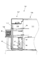
- FIGS As an example of an apparatus in which a substrate transfer robot is used, a typical semiconductor manufacturing apparatus is shown in FIGS.
- the semiconductor manufacturing apparatus 101 transports the wafer W between the wafer processing apparatus 106 that processes the semiconductor wafer W, the FOUP 102 that is a container for storing the wafer W, and the wafer processing apparatus 106 and the FOUP 102. And a wafer transfer device (substrate transfer device).
- a wafer W before or after processing is stored, and in the wafer processing apparatus 106, process processing such as heat treatment, impurity introduction processing, thin film formation processing, lithography processing, cleaning processing, and planarization processing is performed.
- the wafer processing apparatus 106 is filled with the processing space 111, a processing space forming unit 112 in which the processing space 111 is formed, a processing apparatus main body (not shown) that processes the wafer W, and the processing space 111.
- a processing space adjusting device (not shown) for adjusting the atmospheric gas is provided.
- the wafer transfer apparatus 107 includes a preparation space forming unit 117 in which a preparation space 116 is formed, a substrate transfer robot 31 arranged in the preparation space 116, an aligner 119 arranged in the preparation space 116 and adjusting the orientation of the wafer W, A preparation space adjusting device (not shown) for adjusting the atmospheric gas filled in the preparation space 116 is provided.
- the preparation space forming unit 117 is formed in a rectangular parallelepiped box shape, and the substrate transport robot 31 is disposed at a substantially central portion in the longitudinal direction of the preparation space 116.
- the substrate transfer robot 31 takes out the wafer W from the inner space 105 and inserts the wafer W into the inner space 105.
- the substrate transfer robot 31 takes out the wafer W from the processing space 111 and inserts the wafer W into the processing space 111.
- the substrate transfer robot 31 when the wafer transfer robot 31 transfers the wafer W from the FOUP 102 to the wafer processing apparatus 106, the substrate transfer robot 31 once transfers the wafer W taken out from the FOUP 102 to the aligner 119, and performs wafer processing with the same direction of each wafer W. Insert into device 106.
- the substrate transfer robot 31 is a SCARA-type horizontal articulated robot.
- the robot arm 62, a base 63 to which the base end portion of the robot arm 62 is connected, and the tip end portion of the robot arm 62 are connected to each other.
- a robot hand (end effector) 64 for gripping is provided.
- the robot arm 62 has first and second links 65 and 66.
- the base 63 is fixed to the installation surface 45 for moving in the vertical direction for taking out the wafers W stored in a plurality of stages in the upper and lower stages in the hoop 102 and inserting them into the wafer processing apparatus 106.
- It has the fixing
- the elevating unit 47 is provided with a base end portion of the robot arm 62 so as to be able to turn.
- the elevating part 47 is formed in a cylindrical shape, and is provided such that its axis extends in the vertical direction. The upper part of the elevating part 47 becomes the upper part of the base 63. As the elevating unit 47 is driven up and down, the position of the robot hand 64 provided at the tip of the robot arm 62 changes up and down.
- the substrate transfer robot 31 including the base 63 is disposed in the preparation space 116 that is a clean environment, in order to prevent contamination in the lifting part preparation space 116 due to dust or the like generated when the lifting part 47 is raised or lowered.
- the fixing unit 46 and the lifting / lowering unit 47 are housed in a housing 67, and a robot arm 62 is provided at an extending portion of the lifting / lowering unit 47 that penetrates the ceiling portion of the housing 67.
- the size of the preparation space that is, the volume of the preparation space forming unit 117 is as small as possible in order to easily maintain a clean environment.
- Patent Document 1 in order to reduce the size of the preparation space in the depth direction (a direction perpendicular to the direction in which the hoops are arranged), the substrate transfer robot 31 is arranged close to one of the preparation spaces in the depth direction. Thus, the length to the arm tip when the robot arm is contracted is reduced.
- the dimension in the depth direction of the preparation space cannot be smaller than the length of each link constituting the robot arm.
- the substrate transfer robot 31 used in the wafer transfer apparatus 107 can maintain the maximum reachable distance in a horizontal plane at a predetermined size, and can have a length up to the tip of the arm when the robot arm is contracted. There is a conflicting requirement to keep it as short as possible.
- each link constituting the robot arm In order to prevent vibration during operation of the substrate transfer robot, it is necessary to ensure sufficient rigidity of each link constituting the robot arm. To ensure sufficient rigidity, the height of each link in the vertical direction is If the number of links is increased while maintaining the thickness (thickness), the vertical height (thickness) of the entire robot arm increases as the number of links increases, and the minimum height of the hand that holds the wafer is reduced. It becomes higher than before. This causes a problem that the hand cannot access the wafer stored at the lowest position in the hoop.
- the present invention has been made in view of the above-described problems of the prior art, and includes a substrate transfer robot capable of reducing the size of the substrate transfer apparatus without causing inconvenience such as a decrease in the rigidity of the robot arm.
- An object of the present invention is to provide a substrate transfer apparatus provided with a robot.
- a substrate transfer robot includes a robot arm having an end effector at a tip portion for holding a substrate, and a lift drive mechanism for lifting and lowering the robot arm.
- Cover means for covering the elevating drive mechanism, and the elevating drive mechanism is provided with a fixed part provided with a guide rail extending in the vertical direction, and an elevating part driven up and down along the guide rail
- the robot arm has a base link that is pivotally connected to the elevating part, and a link member that is pivotally connected to the base link and includes the tip part, and the cover Means are provided on the fixed part, the fixed part cover in which the elevating part moves, and the guide lever provided on the elevating part and exposed when the elevating part is lowered.
- Having a guide rail cover for covering the upper portion of the Le characterized in that.
- the height of the upper surface of the base link is substantially the same as the height of the upper surface of the fixing part. It is comprised so that it may be lower.
- the upper end of the guide rail cover is substantially the same as the height of the upper surface of the fixing portion when the elevating portion is lowered to the lowest point. It is comprised so that it may be.
- a fourth aspect of the present invention is characterized in that, in any one of the first to third aspects, the link member has two or more links that are pivotably connected to each other.
- a substrate transfer apparatus includes a substrate transfer robot according to any one of the first to fourth aspects, and a preparation space in which the substrate transfer robot is installed. And a forming portion.
- the substrate transfer robot has a base including the lifting drive mechanism, and the base is one of the depth directions inside the preparation space forming portion. It is characterized by being arranged close to.
- the present invention it is possible to provide a substrate transfer robot capable of reducing the size of the substrate transfer apparatus without inconvenience such as a decrease in rigidity of the robot arm.
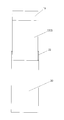
- FIG. 7 is a YY sectional view of FIG. 6.
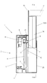
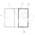
- FIG. 4 is an outline view showing a fixing unit and a lifting unit in a state where the lifting unit is lowered to the lowest point in the substrate transfer robot shown in FIG. 3.
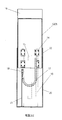
- the top view of FIG. FIG. 4 is an outline view showing a fixing unit and a lifting unit in a state where the lifting unit is raised to the highest point in the substrate transfer robot shown in FIG. 3.
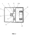
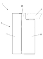
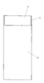
- the right view of FIG. FIG. 4 is a plan view showing a substrate transfer apparatus including the substrate transfer robot shown in FIG. 3.
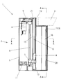
- the substrate transfer robot includes an elevating drive mechanism 1 for elevating the robot arm, and the elevating drive mechanism 1 is fixed to the installation surface.
- Part 2 and elevating part 3 provided on the side of fixed part 2 so as to be elevable.
- a base link 4 of the robot arm is provided on the upper part of the elevating part 3 so as to be horizontally rotatable.
- a hand (end effector) (not shown) for holding the substrate is provided at the tip of the robot arm.
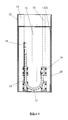
- the fixed portion 2 of the elevating drive mechanism 1 includes a fixed casing 5 having a substantially rectangular parallelepiped shape whose outer shape is vertically long (see FIGS. 3, 4, 8 to 10). Inside the fixed casing 5 are a ball screw 6 for raising and lowering the elevating unit 3, a nut member 7 that engages with the ball screw 6 and moves up and down by the rotation of the ball screw 6, and a motor 8 that rotationally drives the ball screw 6.
- a pulley mechanism 9 serving as a power transmission mechanism for transmitting the driving force of the motor 8 to the ball screw 6 is provided.
- two guide rails 10 extending in the vertical direction are arranged in parallel at a predetermined interval on the outer surface of the side surface of the fixed portion 2 that connects the elevating portion 3. Further, a fan 11 for discharging the internal air from below to the outside and generating a downward air flow inside is disposed at the lower inside of the fixed casing 5.
- the lifting / lowering unit 3 has a substantially rectangular parallelepiped shape whose outer shape is vertically long, has a bottom open, and includes a movable casing 12 having a ceiling surface and four side surfaces connected by a plate-like member (see FIGS. 3 and 4). .
- a movable casing 12 having a ceiling surface and four side surfaces connected by a plate-like member (see FIGS. 3 and 4).
- the support member 13 connected to the nut member 7 in the fixed casing 5 of the fixed portion 2 and the guide rail 10 are engaged and moved up and down.
- a block-like moving body 14 is disposed. Two moving bodies 14 are arranged in series on each of the guide rails 10 for the stability and certainty of traveling.
- a vertically elongated opening 15 having a length corresponding to the lifting stroke is provided (see FIGS. 3 and 4).
- a base link 4 of the robot arm is pivotably provided on the upper surface of the movable casing 12 of the elevating unit 3, and the base link 4 and the link member (one or two) beyond the base link 4 are provided inside the movable casing 12.
- a cable arrangement area 16 is provided in which a power supply cable and a signal cable are routed to a servo motor or the like arranged in the inside of the above link).
- a cable bear (registered trademark) 17 is disposed in the movable casing 12 for processing these cables when the elevating unit 3 is raised and lowered.
- the movable casing 12 when the robot arm is in the lowest position, the movable casing 12 is arranged such that the upper surface of the base link 4 is substantially the same height as the upper surface of the stationary casing 5 as shown in FIG. The height of the top surface is set.
- a horizontal swivel arm mechanism having a first link 65A and a second link 66A in which two links used in a conventional substrate transfer apparatus are shortened is connected to the base link 4.
- the robot arm 62A By configuring the robot arm 62A to be used as a link member, the height position of the hand at the tip of the arm can be maintained the same as before without reducing the rigidity of each link.
- the number of links including the base link 4 can be made three without reducing the rigidity of each link, and the conventional two-link substrate.
- the length of each link can be shortened to achieve the same maximum hand reach distance as the transfer robot.
- the dimension in the depth direction of the preparation space 116 of the wafer transfer device is Since it is set depending on the length of each link of the substrate transport robot, the width of the preparation space can be reduced as the length of each link becomes shorter. That is, according to the substrate transfer robot according to the present embodiment, the length of each link is shorter than that of the conventional one, so that the width of the preparation space can be reduced while ensuring a predetermined maximum hand reachable distance.
- the height of the upper surface of the movable casing 12 is such that the upper surface of the base link 4 is substantially the same as the upper surface of the fixed casing 5. It is set to be.
- the elevating unit 3 is lowered to the lowest point.
- the upper part of the guide rail 10 is exposed. If the upper portion of the guide rail 10 is exposed, the preparation space may be contaminated by dust or the like from the upper portion, so some countermeasure is required.
- the following configuration is employed to prevent contamination using the guide rail 10 as a contamination source.
- a guide rail cover 19 for covering the upper part of the guide rail 10 exposed when the elevating part 3 is lowered is provided on the upper part of the elevating part 3.
- the guide rail cover 19 is formed as an upward extension of the connecting surface of the movable casing 12 to the fixed portion 2.
- the movable casing 12 and the guide rail cover 19 constitute a part of cover means for covering the elevating drive mechanism 1.
- the width of the guide rail cover 19 is substantially the same as the connecting surface of the movable casing 12 to the fixed portion 2, and the height of the guide rail cover 19 is exposed at the position where the elevating portion 3 is lowered to the lowest point. It is set to cover the upper surface of the.
- the guide rail cover 19 is provided on the fixed side in order to minimize the gap between the guide rail 10 and the ceiling cover 21 described later.
- the height of the upper surface of the casing 5 is preferably substantially the same.
- the fixed-side casing 5 includes a fixed-side cover 20 having a side surface and a bottom surface that are close to the outer surface of a side portion of the movable-side casing 12 other than the side portion that is connected to the fixed-side casing 5 and is open at the top. Is provided.
- the fixed-side casing 5 and the fixed-side cover 20 constitute a part of cover means for covering the lifting drive mechanism 1.
- the movable casing 12 constituting the elevating unit 3 can be moved in and out of the fixed cover 20 by moving up and down through the open upper portion of the fixed cover 20, and the movable casing 12 descends to the lowest point. When in this position, the whole or part of the portion below the height of the substantially upper end of the movable casing 12 can be accommodated in the fixed cover 20.
- the side inner surface of the fixed cover 20 has a shape close to the outer side surface of the movable casing 12, the gap between the side inner surface of the fixed side cover 20 and the side outer surface of the movable casing 12 is increased. It is possible to suppress the discharge of dust and the like inside the fixed side cover 20 via the outside.
- the bottom surface of the fixed cover 20 is provided because the interior of the fixed cover 20 communicates with the space in which the guide rail 10 exists when the movable casing 12 is raised (for example, FIG. 6), by forming the inside of the fixed side cover 20 in a closed space, it is to prevent the release of dust and the like to the outside.
- the upper end of the fixed side cover 20 is configured to be higher than the height of the lower end of the movable side casing 12 when the movable side casing 12 is located at the highest position. Thereby, even when the movable casing 12 is in the position raised to the uppermost point, the lower part of the side portion of the movable casing 12 is housed inside the fixed cover 20. Release of dust and the like inside the fixed side cover 20 through the gap between the side inner surface and the side outer surface of the movable casing 12 can be suppressed.
- the upper surface of the fixed casing 5 is connected with a bowl-shaped ceiling part cover 21 whose tip extends over the guide rail 10 to a position close to the guide rail cover 19. Further, a hook-shaped side cover 22 whose front end extends to the position of the guide rail cover 19 or a position beyond the guide rail 10 is connected to the side of the guide rail 10 (FIG. 4).
- FIGS. 6 and 7 Drawings corresponding to FIGS. 3 and 4 at the position where the elevating unit 3 is raised to the highest point are shown in FIGS. 6 and 7, respectively. Moreover, the external views corresponding to FIGS. 3 to 7 are shown in FIGS. 8 to 12, respectively.
- the guide rail 10 mainly includes the guide rail cover 19 and the front surface of the movable casing 12 (connection to the fixed portion 2) when the elevating unit 3 is lowered and positioned below. Part side), a space formed by the ceiling cover 21 and the side cover 22, and when the elevating part 3 is raised and positioned upward, the front side (fixed part) of the movable casing 12 is mainly used. 2, the fixed side cover 20, the ceiling cover 21, and the side cover 22.
- the substrate transfer robot according to the present embodiment maintains the clean atmosphere of the preparation space because the surface of the guide rail 10 that can become a contamination source to the clean atmosphere is not exposed in the entire lifting stroke of the lifting unit 3. Can do.
- the movable casing 12 has a structure in which plate-like members including the front surface are connected, so that the fixed end 18 of the cable bear 17 is fixed.
- the cable is supported by a cable bearer support portion 23 disposed at the bottom of the fixed side cover 20 connected to the fixed side casing 5 of the portion 2, and the cables are arranged below the fixed side cover 20 and the movable side casing 12.
- the terminal of the cable bear fixed end 18 and the terminal board in the fixed casing 5 are connected via the bottom open end or the like.
- the base 63 of the substrate transfer robot is arranged close to the wafer processing apparatus 106 side in the depth direction of the preparation space 116, but close to the hoop 102 side. It may be arranged.
Landscapes
- Engineering & Computer Science (AREA)
- Mechanical Engineering (AREA)
- Robotics (AREA)
- Container, Conveyance, Adherence, Positioning, Of Wafer (AREA)
- Manipulator (AREA)
Abstract
Description
2 固定部
3 昇降部
4 基部リンク
5 固定側ケーシング(固定部用カバー)
6 ボールねじ
7 ナット部材
8 モータ
9 プーリ機構
10 ガイドレール
11 ファン
12 可動側ケーシング
13 支持部材
14 移動体
15 開口
16 ケーブル配置エリア
17 ケーブルベア
18 ケーブルベア固定端部
19 ガイドレール用カバー
20 固定側カバー
21 天井部カバー
22 側部カバー
23 ケーブルベア支持部
62A ロボットアーム
64 ロボットハンド(エンドエフェクタ)
65A 第1リンク
66A 第2リンク
101 半導体製造装置
102 フープ(FOUP)
105 フープ内空間
106 ウェハ処理装置
107 ウェハ搬送装置
111 処理空間
116 準備空間
119 アライナ
W ウェハ
Claims (6)
- 基板を保持するためのエンドエフェクタを先端部に有するロボットアームと、
前記ロボットアームを昇降させるための昇降駆動機構と、
前記昇降駆動機構を覆うためのカバー手段と、を備え、
前記昇降駆動機構は、上下方向に延在するガイドレールが設けられた固定部と、前記ガイドレールに沿って昇降駆動される昇降部と、を有し、
前記ロボットアームは、前記昇降部に旋回可能に連結された基部リンクと、前記基部リンクに旋回可能に連結され、前記先端部を含むリンク部材と、を有し、
前記カバー手段は、前記固定部に設けられ、前記昇降部がその内部を移動する固定側カバーと、前記昇降部に設けられ、前記昇降部が下降した際に露出する前記ガイドレールの上部を覆うためのガイドレール用カバーと、を有する、ことを特徴とする基板搬送ロボット。 - 前記昇降部が最下点まで下降したときに、前記基部リンクの上面の高さが、前記固定部の上面の高さと略同一またはそれより下方であるように構成されている、請求項1記載の基板搬送ロボット。
- 前記昇降部が最下点まで下降したときに、前記ガイドレール用カバーの上端が、前記固定部の上面の高さと略同一であるように構成されている、請求項1または2に記載の基板搬送ロボット。
- 前記リンク部材は、互いに旋回可能に連結された2つ以上のリンクを有する、請求項1乃至3のいずれか一項に記載の基板搬送ロボット。
- 請求項1乃至4のいずれか一項に記載の基板搬送ロボットと、
前記基板搬送ロボットがその内部に設置された準備空間形成部と、を備えた基板搬送装置。 - 前記基板搬送ロボットは、前記昇降駆動機構を含む基台を有し、
前記基台は、前記準備空間形成部の内部の奥行き方向の一方に寄せて配置されている、請求項5記載の基板搬送装置。
Priority Applications (3)
| Application Number | Priority Date | Filing Date | Title |
|---|---|---|---|
| US16/079,603 US10867826B2 (en) | 2016-02-26 | 2017-02-27 | Substrate conveyance robot and substrate conveyance apparatus |
| KR1020187027044A KR102205661B1 (ko) | 2016-02-26 | 2017-02-27 | 기판 반송 로봇 및 기판 반송 장치 |
| CN201780013321.7A CN108698222B (zh) | 2016-02-26 | 2017-02-27 | 衬底搬送机器人及衬底搬送装置 |
Applications Claiming Priority (2)
| Application Number | Priority Date | Filing Date | Title |
|---|---|---|---|
| JP2016036421A JP6901828B2 (ja) | 2016-02-26 | 2016-02-26 | 基板搬送ロボットおよび基板搬送装置 |
| JP2016-036421 | 2016-02-26 |
Publications (1)
| Publication Number | Publication Date |
|---|---|
| WO2017146252A1 true WO2017146252A1 (ja) | 2017-08-31 |
Family
ID=59686363
Family Applications (1)
| Application Number | Title | Priority Date | Filing Date |
|---|---|---|---|
| PCT/JP2017/007362 Ceased WO2017146252A1 (ja) | 2016-02-26 | 2017-02-27 | 基板搬送ロボットおよび基板搬送装置 |
Country Status (6)
| Country | Link |
|---|---|
| US (1) | US10867826B2 (ja) |
| JP (1) | JP6901828B2 (ja) |
| KR (1) | KR102205661B1 (ja) |
| CN (1) | CN108698222B (ja) |
| TW (1) | TWI643797B (ja) |
| WO (1) | WO2017146252A1 (ja) |
Cited By (1)
| Publication number | Priority date | Publication date | Assignee | Title |
|---|---|---|---|---|
| US20240198514A1 (en) * | 2021-04-23 | 2024-06-20 | Kawasaki Jukogyo Kabushiki Kaisha | Substrate conveyor robot and substrate conveying apparatus |
Families Citing this family (10)
| Publication number | Priority date | Publication date | Assignee | Title |
|---|---|---|---|---|
| CN108368916B (zh) * | 2015-11-30 | 2020-04-21 | 生活机器人学股份有限公司 | 直动伸缩机构 |
| WO2017150315A1 (ja) * | 2016-02-29 | 2017-09-08 | ライフロボティクス株式会社 | 直動伸縮機構及びそれを備えたロボットアーム機構 |
| WO2017150318A1 (ja) * | 2016-02-29 | 2017-09-08 | ライフロボティクス株式会社 | ロボットアーム機構及び直動伸縮機構 |
| JP6773768B2 (ja) * | 2016-03-29 | 2020-10-21 | ライフロボティクス株式会社 | ねじり回転関節機構及びロボットアーム機構 |
| JP6725645B2 (ja) * | 2016-03-29 | 2020-07-22 | ライフロボティクス株式会社 | ロボットアーム機構 |
| CN111421571A (zh) * | 2019-01-09 | 2020-07-17 | 苏州吉泰兴机电设备有限公司 | 一种四轴机器人 |
| CN109703972B (zh) * | 2019-02-12 | 2024-05-14 | 合肥憬望智能科技有限公司 | 一种三站合一的自动化晶粒入料装置 |
| US12202124B2 (en) * | 2020-09-03 | 2025-01-21 | Kawasaki Jukogyo Kabushiki Kaisha | Substrate conveying robot |
| JP7662388B2 (ja) * | 2021-04-09 | 2025-04-15 | 川崎重工業株式会社 | 基板搬送ロボットおよび基板搬送装置 |
| CN116352690B (zh) * | 2023-06-01 | 2023-08-22 | 沈阳芯达科技有限公司 | 一种基于大气机械手的垂直行程增程机构 |
Citations (5)
| Publication number | Priority date | Publication date | Assignee | Title |
|---|---|---|---|---|
| JPH0740087U (ja) * | 1993-12-24 | 1995-07-18 | 株式会社安川電機 | ロボット用ジャバラ |
| JP2002338042A (ja) * | 2001-05-15 | 2002-11-27 | Dainippon Screen Mfg Co Ltd | 基板処理装置および基板搬入搬出装置 |
| WO2009066573A1 (ja) * | 2007-11-21 | 2009-05-28 | Kabushiki Kaisha Yaskawa Denki | 搬送ロボット、それを備えた局所クリーン化された筐体、及びそれを備えた半導体製造装置 |
| JP4980127B2 (ja) * | 2007-04-24 | 2012-07-18 | 川崎重工業株式会社 | 基板搬送ロボット |
| JP2015036185A (ja) * | 2013-08-09 | 2015-02-23 | 日本電産サンキョー株式会社 | 産業用ロボット |
Family Cites Families (24)
| Publication number | Priority date | Publication date | Assignee | Title |
|---|---|---|---|---|
| US4904153A (en) * | 1986-11-20 | 1990-02-27 | Shimizu Construction Co., Ltd. | Transporting robot for semiconductor wafers |
| JPH0650758B2 (ja) * | 1986-12-03 | 1994-06-29 | 清水建設株式会社 | 半導体ウエハカセット用移送ロボット |
| US6921467B2 (en) * | 1996-07-15 | 2005-07-26 | Semitool, Inc. | Processing tools, components of processing tools, and method of making and using same for electrochemical processing of microelectronic workpieces |
| JPH11129184A (ja) * | 1997-09-01 | 1999-05-18 | Dainippon Screen Mfg Co Ltd | 基板処理装置および基板搬入搬出装置 |
| JP2000117667A (ja) * | 1998-10-19 | 2000-04-25 | Komatsu Ltd | 円筒座標型ロボット |
| KR100594390B1 (ko) * | 2000-01-28 | 2006-07-03 | 삼성전자주식회사 | 텔레스코픽 시스템을 구비한 로봇 |
| KR100630955B1 (ko) * | 2004-06-18 | 2006-10-02 | 삼성전자주식회사 | 기판 반송장치 |
| US20070020080A1 (en) * | 2004-07-09 | 2007-01-25 | Paul Wirth | Transfer devices and methods for handling microfeature workpieces within an environment of a processing machine |
| JP4579605B2 (ja) * | 2004-07-20 | 2010-11-10 | 川崎重工業株式会社 | 搬送ロボットのアーム構造 |
| US7798764B2 (en) * | 2005-12-22 | 2010-09-21 | Applied Materials, Inc. | Substrate processing sequence in a cartesian robot cluster tool |
| KR101198179B1 (ko) * | 2005-01-17 | 2012-11-16 | 삼성전자주식회사 | 핸들링 로봇의 정적 처짐 보정방법 및 장치 |
| US8573919B2 (en) * | 2005-07-11 | 2013-11-05 | Brooks Automation, Inc. | Substrate transport apparatus |
| US7896602B2 (en) * | 2006-06-09 | 2011-03-01 | Lutz Rebstock | Workpiece stocker with circular configuration |
| JP4849969B2 (ja) * | 2006-06-15 | 2012-01-11 | 東京エレクトロン株式会社 | 基板処理システムおよび基板搬送方法 |
| JP4753092B2 (ja) * | 2007-07-18 | 2011-08-17 | 株式会社安川電機 | 防塵機構を備えた基板搬送ロボット及びそれを備えた半導体製造装置 |
| CN100532026C (zh) * | 2007-12-25 | 2009-08-26 | 大连理工大学 | 一种玻璃基片传输机器人 |
| US7975568B2 (en) * | 2008-04-24 | 2011-07-12 | Asm Technology Singapore Pte Ltd | Robotic arm driving mechanism |
| US9254566B2 (en) * | 2009-03-13 | 2016-02-09 | Kawasaki Jukogyo Kabushiki Kaisha | Robot having end effector and method of operating the same |
| JP5304601B2 (ja) * | 2009-11-10 | 2013-10-02 | 株式会社安川電機 | アーム機構およびそれを備えた真空ロボット |
| JP5755842B2 (ja) * | 2010-04-22 | 2015-07-29 | 株式会社ダイヘン | ワーク搬送システム |
| US20120171002A1 (en) * | 2011-01-05 | 2012-07-05 | Electro Scientific Industries, Inc | Apparatus and method for transferring a substrate |
| JP5885528B2 (ja) * | 2012-02-14 | 2016-03-15 | 株式会社安川電機 | 搬送装置 |
| US11317971B2 (en) * | 2012-06-21 | 2022-05-03 | Globus Medical, Inc. | Systems and methods related to robotic guidance in surgery |
| US10224232B2 (en) * | 2013-01-18 | 2019-03-05 | Persimmon Technologies Corporation | Robot having two arms with unequal link lengths |
-
2016
- 2016-02-26 JP JP2016036421A patent/JP6901828B2/ja active Active
-
2017
- 2017-02-24 TW TW106106475A patent/TWI643797B/zh active
- 2017-02-27 US US16/079,603 patent/US10867826B2/en active Active
- 2017-02-27 WO PCT/JP2017/007362 patent/WO2017146252A1/ja not_active Ceased
- 2017-02-27 KR KR1020187027044A patent/KR102205661B1/ko active Active
- 2017-02-27 CN CN201780013321.7A patent/CN108698222B/zh active Active
Patent Citations (5)
| Publication number | Priority date | Publication date | Assignee | Title |
|---|---|---|---|---|
| JPH0740087U (ja) * | 1993-12-24 | 1995-07-18 | 株式会社安川電機 | ロボット用ジャバラ |
| JP2002338042A (ja) * | 2001-05-15 | 2002-11-27 | Dainippon Screen Mfg Co Ltd | 基板処理装置および基板搬入搬出装置 |
| JP4980127B2 (ja) * | 2007-04-24 | 2012-07-18 | 川崎重工業株式会社 | 基板搬送ロボット |
| WO2009066573A1 (ja) * | 2007-11-21 | 2009-05-28 | Kabushiki Kaisha Yaskawa Denki | 搬送ロボット、それを備えた局所クリーン化された筐体、及びそれを備えた半導体製造装置 |
| JP2015036185A (ja) * | 2013-08-09 | 2015-02-23 | 日本電産サンキョー株式会社 | 産業用ロボット |
Cited By (1)
| Publication number | Priority date | Publication date | Assignee | Title |
|---|---|---|---|---|
| US20240198514A1 (en) * | 2021-04-23 | 2024-06-20 | Kawasaki Jukogyo Kabushiki Kaisha | Substrate conveyor robot and substrate conveying apparatus |
Also Published As
| Publication number | Publication date |
|---|---|
| CN108698222B (zh) | 2021-11-09 |
| JP6901828B2 (ja) | 2021-07-14 |
| KR102205661B1 (ko) | 2021-01-21 |
| JP2017148925A (ja) | 2017-08-31 |
| TW201736233A (zh) | 2017-10-16 |
| CN108698222A (zh) | 2018-10-23 |
| US10867826B2 (en) | 2020-12-15 |
| TWI643797B (zh) | 2018-12-11 |
| KR20180116338A (ko) | 2018-10-24 |
| US20190054613A1 (en) | 2019-02-21 |
Similar Documents
| Publication | Publication Date | Title |
|---|---|---|
| WO2017146252A1 (ja) | 基板搬送ロボットおよび基板搬送装置 | |
| KR101443457B1 (ko) | 반송 로봇 | |
| JP7291760B2 (ja) | キャリッジロボット及びそれを含むタワーリフト | |
| JP6332133B2 (ja) | 容器搬送設備 | |
| TW201814817A (zh) | 高架搬送系統及高架搬送車 | |
| CN1608318A (zh) | 被处理体的搬送装置和具有搬送装置的处理系统 | |
| KR102612257B1 (ko) | 수평 다관절 로봇 및 제조 시스템 | |
| JPWO2016152721A1 (ja) | 基板処理装置および半導体装置の製造方法 | |
| JP6296164B2 (ja) | ロボットシステムおよび搬送方法 | |
| JP5239845B2 (ja) | 基板搬送ロボット、基板搬送装置および半導体製造装置 | |
| JP7662388B2 (ja) | 基板搬送ロボットおよび基板搬送装置 | |
| KR20220139945A (ko) | 로봇 및 이를 구비한 기판 반송 시스템 | |
| JP7732766B2 (ja) | 基板搬送ロボットおよび基板搬送装置 | |
| JP5474328B2 (ja) | 基板搬送ロボット | |
| KR102727087B1 (ko) | 이송 장치 | |
| JP5309324B2 (ja) | 基板搬送システム | |
| TW202234564A (zh) | 產業用機器人 |
Legal Events
| Date | Code | Title | Description |
|---|---|---|---|
| NENP | Non-entry into the national phase |
Ref country code: DE |
|
| ENP | Entry into the national phase |
Ref document number: 20187027044 Country of ref document: KR Kind code of ref document: A |
|
| WWE | Wipo information: entry into national phase |
Ref document number: 1020187027044 Country of ref document: KR |
|
| 121 | Ep: the epo has been informed by wipo that ep was designated in this application |
Ref document number: 17756686 Country of ref document: EP Kind code of ref document: A1 |
|
| 122 | Ep: pct application non-entry in european phase |
Ref document number: 17756686 Country of ref document: EP Kind code of ref document: A1 |