WO2017141534A1 - 演出部材用の台座 - Google Patents
演出部材用の台座 Download PDFInfo
- Publication number
- WO2017141534A1 WO2017141534A1 PCT/JP2016/087258 JP2016087258W WO2017141534A1 WO 2017141534 A1 WO2017141534 A1 WO 2017141534A1 JP 2016087258 W JP2016087258 W JP 2016087258W WO 2017141534 A1 WO2017141534 A1 WO 2017141534A1
- Authority
- WO
- WIPO (PCT)
- Prior art keywords
- support
- leg
- members
- production
- stage
- Prior art date
- Legal status (The legal status is an assumption and is not a legal conclusion. Google has not performed a legal analysis and makes no representation as to the accuracy of the status listed.)
- Ceased
Links
Images

Classifications
-
- A—HUMAN NECESSITIES
- A63—SPORTS; GAMES; AMUSEMENTS
- A63H—TOYS, e.g. TOPS, DOLLS, HOOPS OR BUILDING BLOCKS
- A63H3/00—Dolls
- A63H3/36—Details; Accessories
- A63H3/50—Frames, stands, or wheels for dolls or toy animals
Definitions
- the present invention relates to a pedestal for a production member.
- Patent Document 1 discloses a figure display stand including a support member having a plurality of joints connected to the back surface of a torso constituting a humanoid toy, and a pedestal portion on which the support member is erected.
- the support member described in Patent Document 1 since the pedestal portion is disposed at the foot of the humanoid toy, the degree of freedom in the positional relationship between the pedestal portion and the humanoid toy is low, and the display effect is hindered. Further, the support member described in Patent Document 1 is for supporting only the humanoid toy main body. When exhibiting a production effect related to the humanoid toy, the pedestal and the plurality of joints have an appearance. Bad and unsuitable.
- An object of the present invention is to provide a pedestal for a production member that can produce a sense of depth, realism, realism, etc. of the scene expressed by the main toy by arranging the production member in the vicinity of the main toy. To do.
- the stage for the production member according to the present invention includes a plurality of connecting portions, leg portions that protrude outward from the connecting portions and that can come into contact with the mounting surface, and insertion holes provided in the leg portions.
- the connecting portions are rotatably connected, and the support rods are selectively inserted into the insertion holes from a plurality of types having different longitudinal lengths and / or forms of the support portions, The plurality of types are selectively supported by the support portions.
- the connecting portion may be a support shaft, and the insertion hole may be parallel to the axis of the support shaft.
- the leg members may be connected to each other so that the respective connecting portions are combined with each other so as to be rotatable.
- the leg members may be selectively combined from a plurality of types having different projecting lengths of the leg portions.
- the support portion may be detachable from the support rod.
- any of the leg member, the support rods and the support members may be colorless and transparent.
- the base for the production member which can produce the depth feeling of a scene expressed by the main toy, a realistic feeling, a real feeling, etc. can be provided by arrange
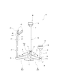
- FIG. 1 is a perspective view showing an embodiment of a usage state of a stage for a production member according to an embodiment of the present invention.
- the stage member base 10 can be used in the vicinity of the exhibited humanoid toys G1 and G2 to support the stage member.
- two fighting humanoid toys G1 and G2 are exhibited, and a stage 10 for a production member is installed in each of the humanoid toys G1 and G2.
- two stage member bases 10, which are the first stage member base 11 and the second stage member base 12 are installed.
- the pedestal 10 for the production member is not distinguished from the pedestal 11 for the first production member and the pedestal 12 for the second production member unless otherwise specified. Will be described.
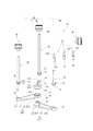
- the stage 10 for the production member has a plurality of leg members 20 placed on the placement surface 60.
- the case of having three leg members 20 is shown, but the case of having two leg members 20 and the case of having three or more leg members 20 are also possible. Note that it is desirable to have three or more leg members 20 because they are stable as a pedestal.
- the leg member 20 has one leg portion 21, and has a support shaft 22 (“connecting portion” in the present invention) at one end portion in the longitudinal direction of the leg portion 21, and at the other end portion. Has an insertion hole 231. Since the leg portion 21 is placed on the placement surface 60, it is desirable to use a linear member having a flat bottom surface. For example, a triangular cross-section member whose bottom surface can contact the placement surface 60 can be used.
- the support shaft 22 is provided at a position obtained by extending the center line of the leg portion 21 in the longitudinal direction.
- the leg portion 21 (leg member 20) protrudes outward of the support shaft 22 (connection portion) with respect to the support shaft 22 (connection portion).
- the support shaft 22 has a planar shape parallel to the bottom surface of the leg portion 21, and each leg member 20 can be connected via the support shaft 22 of each leg member 20.
- the support shaft 221 of the leg member 201 arranged at the lowest position (that is, the placement surface 60 side) has a support shaft plate 24 whose lower surface is flush with the bottom surface of the leg portion 21. On the upper surface of the plate 24, a convex portion 25 protruding upward is provided.
- the support shaft 222 (the “connecting portion” in the present invention) of the leg member 202 attached to the upper side of the leg member 201 is provided with the support shaft plate 26 at the center position in the height direction of the leg member 202.
- the support plate 26 is provided with a through hole 27 into which the convex portion 25 of the support shaft 221 can be inserted.
- the support shaft 223 (the “connecting portion” in the present invention) of the leg member 203 attached to the upper side of the leg member 202 is provided with a support shaft plate 28 at the uppermost position in the height direction of the leg member 203.
- the support plate 28 is provided with a through hole 29 into which the convex portion 25 of the support shaft 221 can be inserted.
- the length of the leg part 21 in each leg member 201, 202, 203 is arbitrary, and if the leg member 201, 202, 203 which has the leg part 21 of various lengths is prepared, it will combine arbitrarily. Can do.
- the through hole 27 of the leg member 202 is externally fitted to the convex portion 25 of the leg member 201
- the through hole 29 of the leg member 203 is externally fitted to the convex portion 25 of the leg member 201 from the upper side of the leg member 202.
- the support shafts 221, 222, and 223 of the three leg members 201, 202, and 203 are connected in a nested manner.
- the outer shape of the convex portion 25 is cylindrical, and the through-hole 27 and the through-hole 29 are circular with an inner diameter larger than the outer diameter of the convex portion 25, so that the three leg members 201, 202, 203 are
- the shaft 22 (the “connecting portion” in the present invention) is connected to be detachable and rotatable (see arrow A in FIG. 2).
- the leg members 201, 202, 203 can be relatively rotated, the relative angles of the leg members 201, 202, 203 are not brought into contact with the main toys G1, G2, and It becomes possible to adjust to an appropriate angle so as to be stable as a pedestal.
- the support shaft 22 ( The “connecting portion” according to the present invention can form a cylindrical shape as a whole and does not impair the aesthetic appearance.
- the protrusion 281 on the lower surface of the support shaft 28 of the leg member 203 it is also possible to provide the circular groove 261 that can be moved by fitting the protrusion 281 on the upper surface of the support shaft 26 of the leg member 202. Thereby, the leg member 202 and the leg member 203 can be connected so that rotation is mutually possible (refer arrow A in FIG. 2).
- a cylindrical support rod insertion portion 23 is provided at a position where the center line of the leg portion 21 extends in the longitudinal direction.
- An insertion hole 231 is provided in the center portion of the support rod insertion portion 23 in a direction orthogonal to the placement surface 60 when the leg member 20 is placed on the placement surface 60. In other words, the insertion hole 231 is provided in a direction parallel to the axis of the support shaft 22.
- the support rod insertion part 23 which has the insertion hole 231 was provided in the end of the leg part 21 was demonstrated, the insertion hole 231 may be directly provided in the leg part 21 without providing the support bar insertion part 23. Is possible.
- the insertion hole 231 is provided in a direction orthogonal to the placement surface 60 when the leg member 20 is placed on the placement surface 60.
- the present invention is not limited to this, and the direction of the insertion hole 231 is arbitrary. Can be determined.
- the support rod 30 is inserted into and supported by the insertion hole 231 of the leg member 20.
- An insertion portion 31 and a flange portion 32 are provided at the lower end portion of the support bar 30.
- the insertion portion 31 is inserted into the insertion hole 231 of the leg member 20 and is supported so that the support rod 30 does not move by cooperation with the flange portion 32.
- the support bar 30 can be formed using a colorless and transparent material, which makes the presence of the support bar 30 relatively comprehensible for viewing each humanoid toy G1, G2 as a main toy together with a production member. It is possible to prevent the viewer from getting the attention.
- a support member 40 (a “support portion” in the present invention) for supporting the effect member 50 is connected to the upper end of the support bar 30.
- the support member 40 includes an attachment portion 41 that inserts the tip of the support rod 30 and is detachably attached to the support rod 30, and an effect member holding portion 42 that holds the effect member 50.
- the support member 40 may be provided on the support bar as an integral part of the support bar 30, but can be attached to and detached from the support bar 30 via the mounting portion 41 as in this embodiment. If it attaches to, even if it is the same support rod 30, it will become possible to replace the support member 40 according to the shape of a production
- the support member 40 can also be formed using a colorless and transparent material, which makes it possible to compare the presence of the support member 40 in appreciating each of the human toys G1 and G2 that are main toys together with the production member. It is possible to avoid the attention of the target viewer.
- Examples of the production member 50 include a plate-like member and an accessory (such as a cut arm) of a main toy, but are not limited thereto. Further, examples of the plate-like production member 50 include a plate describing a character string such as an explanation of a situation shown by a humanoid toy, a character line of a character, and a sound effect, a plate depicting a character's facial expression, and the like.
- a cylindrical member can be used as the mounting portion 41, and the mounting portion 41 has an insertion hole 411 into which the tip of the support rod 30 is detachably inserted.
- the effect member holding unit 42 holds the effect member 50 and does not specify a holding method.
- the support member 40 that sandwiches the effect member 50 in the thickness direction can be used.
- the attachment member 43 that can be fitted into the fitting hole 511 provided in the arm portion 51 is used as the effect member.
- the holding portion 42 can be used.
- the attachment member 43 can also be 1 piece or 3 pieces or more.
- the support member 40 can also be attached to the tip of the support bar 30 via the connection member 33.
- the connection member 33 includes an extension portion 331 that is attached so as to extend the tip of the support bar 30, and an extension attachment portion 332 that is bent at a different angle and that can be attached to the attachment portion 41 of the support member 40.
- the connecting member 33 can be attached to and detached from the support rod 30 and can also be attached to and detached from the support member 40.
- the connection member 33 is prepared in various angles. By selecting the connection member 33 having a desired angle from these, the attachment angle of the effect member 50 supported by the support member 40 with respect to the support rod 40 can be changed. Can be changed easily.
- FIG. 1 shows an example of a state in which the effect member base 10 of the present embodiment is used.
- two humanoid toys G1 and G2 of the pilot boarding type are exhibited, and the arm 61 of the humanoid toy G2 is cut by the weapon 61 held by the humanoid toy G1.
- a pedestal 11 for a first effect member is installed in the vicinity of the humanoid toy G1
- a pedestal 12 for a second effect member is installed in the vicinity of the humanoid toy G2.
- the humanoid toys G1 and G2 are self-supporting or supported by a support member (not shown) for the humanoid toy, and are not supported by the pedestal 10 for the production member, but the pedestal 10 for the production member. May be supported (not shown).
- support members 401 and 402 for supporting the plate-like effect member 50 on the upper portions of the two support rods 301 and 302 are provided. It is attached.
- a support member 40 that supports the arm portion 51 of the humanoid toy G2 cut by the humanoid toy G1 is attached to the upper portion of the support bar 303.
- a plate-shaped image display board 52 is supported on the support bar 301, and can display, for example, the facial expression of a driver on the humanoid toy G1.
- a plate-like character display plate 53 is supported on the support bar 302, and a line or the like referred to by the driver appearing in the humanoid toy G1 is displayed.
- the image display board 52 and the character display board 53 can be plate-like members with printing, engraving, or a printed material, but liquid crystal display boards can also be used.
- the cut arm portion 51 is supported on the upper portion of the support rod 303.
- the base 12 for the second effect member installed in the vicinity of the humanoid toy G2
- the same thing as the base 11 for the first effect member described above can be used.
- a support bar corresponding to the support bar 303 of the base 11 for the first effect member is not provided.
- the character display board 53 is attached to the short support bar 301
- the image display board 52 is attached to the long support bar 302.
- the stage member pedestal 10 includes a leg member 201, 202, and 203 that are pivotably connected to each other with the support shafts 221, 222, and 223 being nested together. 21 can be selectively combined from a plurality of different projecting lengths. Moreover, the length of each support bar 301,302,303 attached to the leg member 20, and the form of the support member 40 attached to the support bar 30 can be selectively used from various things.
- the desired toy G1 is selected from the various leg members 20, the support rods 30, the support members 40, and the production members 50 which are different in length, size, and shape, and is combined with the humanoid toy G1 , G2 can be used to produce effects such as depth, realism, and realism of the scene expressed by the humanoid toys G1, G2.
- the support member 40 may be detachable from the support bar 30. Thereby, various support members 40 can be easily combined.
- the support member 40 may be formed integrally with the support bar 30. Accordingly, since the shape of the support member 40 (support portion) is naturally determined when the support rod 30 is selected, a user who is unfamiliar with the play of placing the production member in the vicinity of the main toys humanoid toys G1 and G2. Therefore, it becomes easy to play because the production member can be appropriately arranged at an appropriate position.
- any one of the leg members 20, the support rods 30, and the support members 40 may be colorless and transparent.
- the presence of the pedestal 10 itself for the production member can be diluted, and the humanoid toys G1 and G2 and the production member 50 can be made conspicuous. Etc. can be produced.
- the base for the production member of the present invention is not limited to the above-described embodiment, and appropriate modifications, improvements, and the like are possible.
Landscapes
- Toys (AREA)
Abstract
【課題】演出部材を主たる玩具の近傍に配置することにより奥行感、臨場感、リアル感等を演出できる演出部材用の台座を提供する。 【解決手段】各脚部材201、202、203は、各支軸221、222、223が互いに回動可能に連結される。また、脚部材20に取り付けられる各支持棒301、302、303の長さ及び支持棒30に設けられる支持部材40の形態は、種々のものから選択的に用いることができる。このため、長さ、大きさ、及び形状のいずれかが異なる種々の支持棒30、支持部材40および演出部材50を選択して組み合わせ、人型玩具G1,G2の近傍に載置することにより、人型玩具G1,G2によって表現されている情景の、奥行感、臨場感、リアル感等を演出することができる。
Description
本発明は、演出部材用の台座に関する。
従来、例えば2本脚の人型玩具を立った状態や所望の状態で飾るとき、自立させることが困難であるため、スタンド等の支持部材を用いるのが一般的である(特許文献1参照)。
特許文献1には、人型玩具を構成する胴部の背面に接続される複数の関節を有する支持部材と、支持部材を立設する台座部とを備えるフィギュア用ディスプレイスタンドが示されている。
特許文献1には、人型玩具を構成する胴部の背面に接続される複数の関節を有する支持部材と、支持部材を立設する台座部とを備えるフィギュア用ディスプレイスタンドが示されている。
しかしながら、特許文献1に記載の支持部材では、人型玩具の足元に台座部を配置するため、台座部と人型玩具との位置関係について自由度が低く、展示効果を阻害する。
また、特許文献1に記載の支持部材は、人型玩具本体のみを支持するためのものであり、人型玩具に関連した演出効果を展示する場合には台座部と複数の関節が外観性を悪くし、適さない。
また、特許文献1に記載の支持部材は、人型玩具本体のみを支持するためのものであり、人型玩具に関連した演出効果を展示する場合には台座部と複数の関節が外観性を悪くし、適さない。
本発明は、演出部材を主たる玩具の近傍に配置することにより、主たる玩具によって表現されている情景の奥行感、臨場感、リアル感等を演出できる演出部材用の台座を提供することを目的とする。
本発明に係る演出部材用の台座は、連結部と、当該連結部の外方に突出するとともに載置面に接触可能な脚部と、前記脚部に設けられた挿入孔と、を有する複数の脚部材と、前記各挿入孔に挿入される支持棒と、前記各支持棒に連結される支持部と、前記各支持部に支持される演出部材と、を備え、前記各脚部材は、前記各連結部が回動可能に連結され、前記各支持棒は、長手方向長さ及び/または前記支持部の形態が異なる複数種類から選択的に前記各挿入孔に挿入され、前記演出部材は、複数種類から選択的に前記各支持部に支持されることを特徴とする。
また、本発明に係る演出部材用の台座においては、前記連結部は支軸であり、前記挿入孔は、前記支軸の軸線に対して平行であるようにしてもよい。
また、本発明に係る演出部材用の台座においては、前記各脚部材は、前記各連結部が互いに入れ子上に組み合わせられて互いに回動可能に連結されるようにしてもよい。
また、本発明に係る演出部材用の台座においては、前記各脚部材は、前記脚部の突出長さが異なる複数種類から選択的に組み合わせられるようにしてもよい。
また、本発明に係る演出部材用の台座においては、前記支持部は、前記支持棒に対して着脱可能であってもよい。
また、本発明に係る演出部材用の台座においては、前記脚部材、前記各支持棒及び前記各支持部材のいずれかは、無色透明であってもよい。
本発明によれば、演出部材を主たる玩具の近傍に配置することにより主たる玩具によって表現されている情景の奥行感、臨場感、リアル感等を演出できる演出部材用の台座を提供することができる。
[本発明の実施の形態]
図1は、本発明の実施形態である演出部材用の台座の使用状態の一形態を示す斜視図である。
図1は、本発明の実施形態である演出部材用の台座の使用状態の一形態を示す斜視図である。
図1に示すように、演出部材用の台座10は、展示した人型玩具G1、G2の近傍に設置して演出部材を支持することに用いることができる。
ここでは、戦う2台の人型玩具G1、G2が展示されており、各人型玩具G1、G2にそれぞれ演出部材用の台座10が設置されている。従って、第1の演出部材用の台座11及び第2の演出部材用の台座12の2台の演出部材用の台座10が設置されている。
なお、図2及び図3の説明においては、特に明示する場合を除いて第1の演出部材用の台座11及び第2の演出部材用の台座12を区別せずに、演出部材用の台座10として説明する。
ここでは、戦う2台の人型玩具G1、G2が展示されており、各人型玩具G1、G2にそれぞれ演出部材用の台座10が設置されている。従って、第1の演出部材用の台座11及び第2の演出部材用の台座12の2台の演出部材用の台座10が設置されている。
なお、図2及び図3の説明においては、特に明示する場合を除いて第1の演出部材用の台座11及び第2の演出部材用の台座12を区別せずに、演出部材用の台座10として説明する。
図2及び図3に示すように、演出部材用の台座10は、載置面60に載置される複数の脚部材20を有する。
ここでは、3個の脚部材20を有する場合をして示しているが、2個の脚部材20を有する場合及び3個以上の脚部材20を有する場合も可能である。なお、3個以上の脚部材20を有すると、台座として安定するため望ましい。
ここでは、3個の脚部材20を有する場合をして示しているが、2個の脚部材20を有する場合及び3個以上の脚部材20を有する場合も可能である。なお、3個以上の脚部材20を有すると、台座として安定するため望ましい。
脚部材20は、1本の脚部21を有しており、脚部21の長手方向一方の端部に支軸22(本発明にいう「連結部」)を有するとともに、他方の端部には挿入孔231を有する。
脚部21は載置面60に載置されるため、下面が平坦な直線状の部材を用いるのが望ましい。例えば、底面が載置面60に接触可能な三角形断面の部材を用いることができる。
脚部21は載置面60に載置されるため、下面が平坦な直線状の部材を用いるのが望ましい。例えば、底面が載置面60に接触可能な三角形断面の部材を用いることができる。
支軸22は、脚部21の中心線を長手方向に延長した位置に設けられている。別言すれば、脚部21(脚部材20)は、支軸22(連結部)に対して支軸22(連結部)の外方に突出している。支軸22は、脚部21の底面と平行な面状を呈しており、各脚部材20の支軸22を介して、各脚部材20が連結可能となっている。
例えば、最も下(すなわち、載置面60側)に配置される脚部材201の支軸221は、下面が脚部21の底面と同一面にある支軸板24を有しており、支軸板24の上面には、上方に突出する凸部25が設けられている。
例えば、最も下(すなわち、載置面60側)に配置される脚部材201の支軸221は、下面が脚部21の底面と同一面にある支軸板24を有しており、支軸板24の上面には、上方に突出する凸部25が設けられている。
また、脚部材201の上側に取り付けられる脚部材202の支軸222(本発明にいう「連結部」)は、脚部材202の高さ方向の中央位置に支軸板26が設けられている。支軸板26には、支軸221の凸部25が挿入可能な貫通孔27が設けられている。
さらに、脚部材202の上側に取り付けられる脚部材203の支軸223(本発明にいう「連結部」)は、脚部材203の高さ方向の最上位置に、支軸板28が設けられている。支軸板28には、支軸221の凸部25が挿入可能な貫通孔29が設けられている。
なお、各脚部材201、202、203における脚部21の長さは任意であり、種々の長さの脚部21を有する脚部材201、202、203を用意しておけば、任意に組み合わせることができる。
さらに、脚部材202の上側に取り付けられる脚部材203の支軸223(本発明にいう「連結部」)は、脚部材203の高さ方向の最上位置に、支軸板28が設けられている。支軸板28には、支軸221の凸部25が挿入可能な貫通孔29が設けられている。
なお、各脚部材201、202、203における脚部21の長さは任意であり、種々の長さの脚部21を有する脚部材201、202、203を用意しておけば、任意に組み合わせることができる。
従って、脚部材201の凸部25に脚部材202の貫通孔27を上側から外嵌し、さらに、脚部材202の上側から脚部材203の貫通孔29を脚部材201の凸部25に外嵌する。これにより、3個の脚部材201、202、203の支軸221、222、223が入れ子状に連結される。
このとき、凸部25の外形を円筒状とし、貫通孔27及び貫通孔29を凸部25の外径よりも大きな内径を有する円形とすることにより、3個の脚部材201、202、203は、支軸22(本発明にいう「連結部」)を中心として着脱可能かつ回動可能に連結される(図2中矢印A参照)。
これにより、脚部材201、202、203を相対的に回動できるので、脚部材201、202、203の相対的な角度を、主たる玩具である各人型玩具G1、G2に接触せず、かつ、台座として安定するような適切な角度に調節することが可能になる。
このとき、凸部25の外形を円筒状とし、貫通孔27及び貫通孔29を凸部25の外径よりも大きな内径を有する円形とすることにより、3個の脚部材201、202、203は、支軸22(本発明にいう「連結部」)を中心として着脱可能かつ回動可能に連結される(図2中矢印A参照)。
これにより、脚部材201、202、203を相対的に回動できるので、脚部材201、202、203の相対的な角度を、主たる玩具である各人型玩具G1、G2に接触せず、かつ、台座として安定するような適切な角度に調節することが可能になる。
また、支軸板24、支軸板26及び支軸板28の板厚及び設ける高さ位置を調整することにより、3個の脚部材201、202、203を組み合わせた際に、支軸22(本発明にいう「連結部」)は全体として円筒形状を形成することができ、美観を損ねない。
なお、脚部材203の支軸板28の下面に突起281を設けるとともに、脚部材202の支軸板26の上面に突起281が嵌入して移動可能な円形の溝261を設けることもできる。これにより、脚部材202と脚部材203とを、相互に回動可能に連結することができる(図2中矢印A参照)。
なお、脚部材203の支軸板28の下面に突起281を設けるとともに、脚部材202の支軸板26の上面に突起281が嵌入して移動可能な円形の溝261を設けることもできる。これにより、脚部材202と脚部材203とを、相互に回動可能に連結することができる(図2中矢印A参照)。
脚部21の他方の端部には、脚部21の中心線を長手方向に延長する位置に、例えば円筒形状の支持棒挿入部23が設けられている。支持棒挿入部23の中央部には、脚部材20を載置面60に載置した際に載置面60と直交する方向に挿入孔231が設けられている。別言すれば、挿入孔231は支軸22の軸線と平行な方向に設けられていることになる。
なお、脚部21の一端に、挿入孔231を有する支持棒挿入部23を設けた場合を説明したが、支持棒挿入部23を設けることなく、挿入孔231を脚部21に直接設けることも可能である。また、本実施形態においては挿入孔231は脚部材20を載置面60に載置した際に載置面60と直交する方向に設けたが、これに限られず、挿入孔231の方向は任意に定めることができる。
なお、脚部21の一端に、挿入孔231を有する支持棒挿入部23を設けた場合を説明したが、支持棒挿入部23を設けることなく、挿入孔231を脚部21に直接設けることも可能である。また、本実施形態においては挿入孔231は脚部材20を載置面60に載置した際に載置面60と直交する方向に設けたが、これに限られず、挿入孔231の方向は任意に定めることができる。
脚部材20の挿入孔231には、支持棒30が挿入されて支持される。支持棒30の下端部には挿入部31及び鍔部32が設けられている。挿入部31は脚部材20の挿入孔231に挿入され、鍔部32との協働により、支持棒30が動かないように支持される。支持棒30は、無色透明の材料を用いて形成することができ、このことにより、主たる玩具である各人型玩具G1、G2を演出部材とともに鑑賞する上で、支持棒30の存在が比較的見る者の注意を引かないようにすることができる。
支持棒30の上端には、演出部材50を支持するための支持部材40(本発明にいう「支持部」)が連結される。支持部材40は、支持棒30の先端を挿入して支持棒30に着脱可能に取り付ける取付部41と、演出部材50を保持する演出部材保持部42を有する。
なお、支持部材40は、支持棒30と一体のものとして支持棒に設けられていてもよいことは勿論であるが、本実施形態のように、取付部41を介して支持棒30に着脱自在に取り付けるようにすれば、同じ支持棒30でも、演出部材の形状に応じて支持部材40を付け替えることできるようになり、利便性が高い。また、支持部材40も無色透明の材料を用いて形成することができ、このことにより、主たる玩具である各人型玩具G1、G2を演出部材とともに鑑賞する上で、支持部材40の存在が比較的見る者の注意を引かないようにすることができる。
なお、支持部材40は、支持棒30と一体のものとして支持棒に設けられていてもよいことは勿論であるが、本実施形態のように、取付部41を介して支持棒30に着脱自在に取り付けるようにすれば、同じ支持棒30でも、演出部材の形状に応じて支持部材40を付け替えることできるようになり、利便性が高い。また、支持部材40も無色透明の材料を用いて形成することができ、このことにより、主たる玩具である各人型玩具G1、G2を演出部材とともに鑑賞する上で、支持部材40の存在が比較的見る者の注意を引かないようにすることができる。
演出部材50としては、プレート状のものや、主たる玩具の付属物(切断された腕部等)等があるが、これに限定するものではない。
また、プレート状の演出部材50としては、人型玩具が示す状況の説明、登場人物の台詞、効果音等の文字列を記載したプレートや、登場人物の表情を描いたプレート等が例示できる。
また、プレート状の演出部材50としては、人型玩具が示す状況の説明、登場人物の台詞、効果音等の文字列を記載したプレートや、登場人物の表情を描いたプレート等が例示できる。
取付部41は、例えば円筒部材を用いることができ、支持棒30の先端を着脱可能に挿入する挿入孔411を有する。
演出部材保持部42は、演出部材50を保持するものであり、保持方法は特定しない。例えば、演出部材50がプレート状である場合には、支持部材40として演出部材50を厚さ方向に挟むものを用いることができる。
演出部材保持部42は、演出部材50を保持するものであり、保持方法は特定しない。例えば、演出部材50がプレート状である場合には、支持部材40として演出部材50を厚さ方向に挟むものを用いることができる。
あるいは、演出部材50が切断された腕部51(図1参照)のような物である場合には、腕部51に設けられている嵌合孔511に嵌合可能な取付部材43を演出部材保持部42として用いることができる。
なお、図2においては、2個の取付部材43を有する支持部材40を例示しているが、取付部材43は、1個あるいは3個以上でも可能である。
なお、図2においては、2個の取付部材43を有する支持部材40を例示しているが、取付部材43は、1個あるいは3個以上でも可能である。
支持部材40は、接続部材33を介して支持棒30の先端に取り付けることもできる。接続部材33は、支持棒30の先端を延長するように取り付ける延長部331と、異なる角度で屈曲され、先端が支持部材40の取付部41に取り付け可能な延長取付部332とを有する。なお、接続部材33は支持棒30に対して着脱可能であるとともに、支持部材40に対しても着脱可能である。
接続部材33は様々な角度のものが用意されており、この中から所望の角度の接続部材33を選択することにより、支持部材40で支持している演出部材50の支持棒40に対する取付角度を、容易に変えることができる。
接続部材33は様々な角度のものが用意されており、この中から所望の角度の接続部材33を選択することにより、支持部材40で支持している演出部材50の支持棒40に対する取付角度を、容易に変えることができる。
図1には、本実施形態の演出部材用の台座10を用いた状態の一例が示されている。ここでは、操縦者搭乗型の2個の人型玩具G1、G2が展示されており、人型玩具G1が保持している武器61で、人型玩具G2の腕部51を切断した状況が示されている。
人型玩具G1の近傍には、第1の演出部材用の台座11が設置されており、人型玩具G2の近傍には、第2の演出部材用の台座12が設置されている。なお、人型玩具G1、G2は、自立可能あるいは人型玩具用の支持部材(図示省略)で支持されており、演出部材用の台座10では支持されてはいないが、演出部材用の台座10で支持するようにしてもよい(図示省略)。
人型玩具G1の近傍には、第1の演出部材用の台座11が設置されており、人型玩具G2の近傍には、第2の演出部材用の台座12が設置されている。なお、人型玩具G1、G2は、自立可能あるいは人型玩具用の支持部材(図示省略)で支持されており、演出部材用の台座10では支持されてはいないが、演出部材用の台座10で支持するようにしてもよい(図示省略)。
人型玩具G1の近傍に設置されている第1の演出部材用の台座11では、2本の支持棒301、302の上部にプレート状の演出部材50を支持するための支持部材401,402が取り付けられている。また、支持棒303の上部には、人型玩具G1によって切断された人型玩具G2の腕部51を支持する支持部材40が取り付けられている。
支持棒301には、プレート状の画像表示板52が支持されており、例えば人型玩具G1に搭乗している操縦者の表情等を表示することができる。支持棒302には、プレート状の文字表示板53が支持されており、人型玩具G1に登場している操縦者が云うセリフ等が表示されている。なお、画像表示板52及び文字表示板53は、印刷または刻印または印刷物を貼った板状の部材を用いることができるが、液晶表示板を用いることもできる。
また、支持棒303の上部には、切断された腕部51が支持されている。
また、支持棒303の上部には、切断された腕部51が支持されている。
人型玩具G2の近傍に設置されている第2の演出部材用の台座12は、上述した第1の演出部材用の台座11と同様のものを用いることができる。ここでは、切断された腕部51に該当するものはないので、第1の演出部材用の台座11の支持棒303に対応する支持棒は設けられていない。また、短い支持棒301に文字表示板53をとりつけ、長い支持棒302に画像表示板52をとりつけている。
次に、本実施形態に係る演出部材用の台座10の作用、効果について説明する。
本実施形態に係る演出部材用の台座10は、各脚部材201、202、203は、各支軸221、222、223が互いに入れ子状に組み合わせられて回動可能に連結されるとともに、脚部21の突出長さが異なる複数種類から選択的に組み合わせることができる。
また、脚部材20に取り付けられる各支持棒301、302、303の長さ及び支持棒30に取り付けられる支持部材40の形態は、種々のものから選択的に用いることができる。
本実施形態に係る演出部材用の台座10は、各脚部材201、202、203は、各支軸221、222、223が互いに入れ子状に組み合わせられて回動可能に連結されるとともに、脚部21の突出長さが異なる複数種類から選択的に組み合わせることができる。
また、脚部材20に取り付けられる各支持棒301、302、303の長さ及び支持棒30に取り付けられる支持部材40の形態は、種々のものから選択的に用いることができる。
このため、長さ、大きさ、及び形状のいずれかが異なる種々の脚部材20、支持棒30、支持部材40、および演出部材50の中から所望のものを選択して組み合わせ、人型玩具G1,G2の近傍に載置することにより、人型玩具G1,G2によって表現されている情景の、奥行感、臨場感、リアル感等の効果を演出することができる。
また、本実施形態に係る演出部材用の台座10においては、支持部材40は、支持棒30に対して着脱可能であってもよい。
これにより、種々の支持部材40を容易に組み合わせることができる。
これにより、種々の支持部材40を容易に組み合わせることができる。
また、本実施形態に係る演出部材用の台座10においては、支持部材40は、支持棒30と一体に形成されていてもよい。
これにより、支持棒30を選択すると自ずと支持部材40(支持部)の形状も決まることになるので、主たる玩具である人型玩具G1,G2の近傍に演出部材を配置する遊びに不慣れな使用者にとっては適切に演出部材を適切な位置に配置できるようになり遊びやすい。
これにより、支持棒30を選択すると自ずと支持部材40(支持部)の形状も決まることになるので、主たる玩具である人型玩具G1,G2の近傍に演出部材を配置する遊びに不慣れな使用者にとっては適切に演出部材を適切な位置に配置できるようになり遊びやすい。
さらに、本実施形態に係る演出部材用の台座10においては、各脚部材20、各支持棒30及び各支持部材40のいずれかが、無色透明であってもよい。
これにより、演出部材用の台座10自体の存在感を希薄化でき、人型玩具G1、G2及び演出部材50を目立たせることができるので、外観性が良くなり、奥行感、臨場感、リアル感等を演出することができる。
これにより、演出部材用の台座10自体の存在感を希薄化でき、人型玩具G1、G2及び演出部材50を目立たせることができるので、外観性が良くなり、奥行感、臨場感、リアル感等を演出することができる。
本発明の演出部材用の台座は、前述した実施形態に限定されるものでなく、適宜な変形,改良等が可能である。
10 演出部材用の台座
20、201、202、203 脚部材
21 脚部
22、221、222、223 支軸(連結部)
231 挿入孔
30、301、302、303 支持棒
40 支持部材(支持部)
50 演出部材
60 載置面
20、201、202、203 脚部材
21 脚部
22、221、222、223 支軸(連結部)
231 挿入孔
30、301、302、303 支持棒
40 支持部材(支持部)
50 演出部材
60 載置面
Claims (6)
- 連結部と、当該連結部の外方に突出するとともに載置面に接触可能な脚部と、前記脚部に設けられた挿入孔と、を有する複数の脚部材と、
前記各挿入孔に挿入される支持棒と、
前記各支持棒に設けられた支持部と、
前記各支持部に支持される演出部材と、を備え、
前記各脚部材は、前記各連結部が互いに回動可能に連結され、
前記各支持棒は、長手方向長さ及び/または前記支持部の形態が異なる複数種類から選択的に前記各挿入孔に挿入され、
前記演出部材は、複数種類から選択的に前記各支持部に支持される演出部材用の台座。 - 請求項1記載の演出部材用の台座であって、
前記連結部は支軸であり、
前記挿入孔は、前記支軸の軸線に対して平行であることを特徴とする演出部材用の台座。 - 請求項1又は2記載の演出部材用の台座であって、
前記各脚部材は、前記各連結部が互いに入れ子上に組み合わせられて互いに回動可能に連結されることを特徴とする演出部材用の台座。 - 請求項1乃至3のいずれか1項に記載の演出部材用の台座であって、
前記各脚部材は、前記脚部の突出長さが異なる複数種類から選択的に組み合わせられることを特徴とする演出部材用の台座。 - 請求項1乃至4のいずれか1項記載の演出部材用の台座であって、
前記支持部は、前記支持棒に対して着脱可能である演出部材用の台座。 - 請求項1乃至5のいずれか1項記載の演出部材用の台座であって、
前記脚部材、前記各支持棒及び前記各支持部のいずれかは、無色透明である演出部材用の台座。
Priority Applications (2)
| Application Number | Priority Date | Filing Date | Title |
|---|---|---|---|
| CN202011020827.0A CN112190959B (zh) | 2016-02-16 | 2016-12-14 | 演出构件用的支座 |
| CN201680078887.3A CN108463275B (zh) | 2016-02-16 | 2016-12-14 | 演出构件用的支座 |
Applications Claiming Priority (2)
| Application Number | Priority Date | Filing Date | Title |
|---|---|---|---|
| JP2016-026503 | 2016-02-16 | ||
| JP2016026503A JP6013635B1 (ja) | 2016-02-16 | 2016-02-16 | 演出部材用の台座 |
Publications (1)
| Publication Number | Publication Date |
|---|---|
| WO2017141534A1 true WO2017141534A1 (ja) | 2017-08-24 |
Family
ID=57145184
Family Applications (1)
| Application Number | Title | Priority Date | Filing Date |
|---|---|---|---|
| PCT/JP2016/087258 Ceased WO2017141534A1 (ja) | 2016-02-16 | 2016-12-14 | 演出部材用の台座 |
Country Status (3)
| Country | Link |
|---|---|
| JP (1) | JP6013635B1 (ja) |
| CN (2) | CN108463275B (ja) |
| WO (1) | WO2017141534A1 (ja) |
Citations (5)
| Publication number | Priority date | Publication date | Assignee | Title |
|---|---|---|---|---|
| JP2003325992A (ja) * | 2002-05-08 | 2003-11-18 | Takara Co Ltd | 人形玩具 |
| US6739936B1 (en) * | 2003-09-25 | 2004-05-25 | Anthony Cotilletta | Toy support apparatus |
| JP3119126U (ja) * | 2005-11-28 | 2006-02-16 | 株式会社マコム | コレクション・ケース |
| JP3165309U (ja) * | 2010-10-28 | 2011-01-13 | 株式会社ヤマト | フィギュア用ディスプレースタンド |
| JP3196196U (ja) * | 2014-12-12 | 2015-02-26 | 株式会社タカラトミー | 人形 |
Family Cites Families (23)
| Publication number | Priority date | Publication date | Assignee | Title |
|---|---|---|---|---|
| JP3165309B2 (ja) * | 1993-12-22 | 2001-05-14 | 株式会社日立製作所 | 粒子画像解析装置 |
| US5475460A (en) * | 1994-03-30 | 1995-12-12 | Eastman Kodak Company | Photographic play set having improved lighting |
| JP3119126B2 (ja) * | 1995-06-20 | 2000-12-18 | トヨタ自動車株式会社 | 車輌の旋回補助装置 |
| JP3196196B2 (ja) * | 1997-06-30 | 2001-08-06 | 日本電気株式会社 | コネクションレス通信の多重度方式 |
| CN2394281Y (zh) * | 1999-09-10 | 2000-08-30 | 姚福财 | 太阳系九大行星模型演示仪 |
| JP2004298592A (ja) * | 2003-03-31 | 2004-10-28 | Kazuo Saito | 和人形および装飾品 |
| JP3154322U (ja) * | 2009-07-27 | 2009-10-15 | 有限会社ダイスプロジェクト | 玩具支持台のアーム部 |
| CN202207461U (zh) * | 2011-06-28 | 2012-05-02 | 韩馥光 | 会旋转的玩偶 |
| JP3174188U (ja) * | 2011-12-27 | 2012-03-08 | 有限会社北村人形 | 人形飾り台 |
| CN202777826U (zh) * | 2012-06-15 | 2013-03-13 | 西安理工大学 | 一种迪斯科游艺机模型玩具 |
| CN102705139B (zh) * | 2012-06-26 | 2014-04-16 | 西北工业大学 | 一种回转体水下航行器发电装置 |
| JP5553871B2 (ja) * | 2012-09-25 | 2014-07-16 | 株式会社バンダイ | 対戦ゲーム用ゲームピースおよび対戦ゲームセット |
| CN203235247U (zh) * | 2013-03-08 | 2013-10-16 | 韩秀香 | 一种造型多变的田径运动人偶玩具 |
| JP5952798B2 (ja) * | 2013-10-25 | 2016-07-13 | 賢治 井上 | 介護移動用カート |
| CN203838966U (zh) * | 2014-05-28 | 2014-09-17 | 石舜 | 地理教学用演示仪 |
| CN204121743U (zh) * | 2014-09-22 | 2015-01-28 | 广州市我扬文化发展有限公司 | 一种可使软体玩具站立的支撑结构 |
| JP6126642B2 (ja) * | 2015-05-28 | 2017-05-10 | 株式会社インフォセレクション | 模型が配置されたポールハンガー |
| CN205140375U (zh) * | 2015-10-27 | 2016-04-06 | 于洪雷 | 一种地理教学用模型 |
| CN205824522U (zh) * | 2016-07-13 | 2016-12-21 | 合肥盈川信息技术有限公司 | 一种用于多屏幕的拼接桌面式支架挂架 |
| CN106157796A (zh) * | 2016-08-29 | 2016-11-23 | 郑云龙 | 一种太阳系行星运转演示教具 |
| CN109744796A (zh) * | 2017-11-01 | 2019-05-14 | 于存强 | 一种经济类教学展示架 |
| CN208212516U (zh) * | 2017-12-29 | 2018-12-11 | 广东可儿玩具有限公司 | 一种娃娃用三点稳定支架 |
| CN211513408U (zh) * | 2020-01-15 | 2020-09-18 | 李睿天 | 一种学前儿童发展心理学演示玩具 |
-
2016
- 2016-02-16 JP JP2016026503A patent/JP6013635B1/ja active Active
- 2016-12-14 CN CN201680078887.3A patent/CN108463275B/zh active Active
- 2016-12-14 CN CN202011020827.0A patent/CN112190959B/zh active Active
- 2016-12-14 WO PCT/JP2016/087258 patent/WO2017141534A1/ja not_active Ceased
Patent Citations (5)
| Publication number | Priority date | Publication date | Assignee | Title |
|---|---|---|---|---|
| JP2003325992A (ja) * | 2002-05-08 | 2003-11-18 | Takara Co Ltd | 人形玩具 |
| US6739936B1 (en) * | 2003-09-25 | 2004-05-25 | Anthony Cotilletta | Toy support apparatus |
| JP3119126U (ja) * | 2005-11-28 | 2006-02-16 | 株式会社マコム | コレクション・ケース |
| JP3165309U (ja) * | 2010-10-28 | 2011-01-13 | 株式会社ヤマト | フィギュア用ディスプレースタンド |
| JP3196196U (ja) * | 2014-12-12 | 2015-02-26 | 株式会社タカラトミー | 人形 |
Non-Patent Citations (1)
| Title |
|---|
| DI:STAGE, 8 January 2015 (2015-01-08), Retrieved from the Internet <URL:http://web.archive.org/web/20150108164843/http://www.goodsmile.info/ja/product/2462/di+stage+%E5%9F%BA%E6%9C%AC+%E3%83%99%E3%83%BC%E3%82%B7%E3%83%83%E3%82%AF+%E3%82%BB%E3%83%83%E3%83%88.html> * |
Also Published As
| Publication number | Publication date |
|---|---|
| CN112190959B (zh) | 2022-07-19 |
| JP6013635B1 (ja) | 2016-10-25 |
| JP2017143937A (ja) | 2017-08-24 |
| CN108463275A (zh) | 2018-08-28 |
| CN112190959A (zh) | 2021-01-08 |
| CN108463275B (zh) | 2020-10-23 |
Similar Documents
| Publication | Publication Date | Title |
|---|---|---|
| JP2023004896A (ja) | 玩具 | |
| JP6941713B2 (ja) | 演出部材用の台座 | |
| US20070117494A1 (en) | Wobbly supports for removable toy figures for use individually, in toy vehicles, and in playsets, including earthquake playsets | |
| JP2025003718A (ja) | 演出部材用の台座 | |
| JP6013635B1 (ja) | 演出部材用の台座 | |
| JP2017144220A (ja) | 演出部材用の台座 | |
| US20140199677A1 (en) | Modular Multi-Element Constructions From Rearrangeable Pieces And Kits Allowing Construction Of Same | |
| US7980015B2 (en) | Bobblehead sign display | |
| KR20110097435A (ko) | 퍼즐식 조형물 | |
| JP3217978U (ja) | ミニキャンバス玩具セット | |
| JP7739534B1 (ja) | 玩具及び展示部材 | |
| JP5041280B2 (ja) | フラワーアレンジメント用具 | |
| JP3157645U (ja) | 展示用スタンド | |
| KR20080044985A (ko) | 블록 완구 세트 | |
| TW200815076A (en) | Manufacturing method of sculptured figure doll | |
| JP2007002960A (ja) | 板材連結具および棚構造 | |
| JP6030517B2 (ja) | 組立構成するダーツボード | |
| JP3156825U (ja) | 組立式シート製玩具 | |
| KR200404974Y1 (ko) | 장식자석놀이완구 | |
| EP3115092A2 (en) | Storytelling game | |
| JP3194271U (ja) | 組み合わせパズルおもちゃ | |
| JP4664317B2 (ja) | 紙製人形 | |
| JP3199831U (ja) | 飾り体 | |
| KR200305671Y1 (ko) | 종이접기 칠교 놀이교구 | |
| WO2011158391A1 (ja) | チェス駒 |
Legal Events
| Date | Code | Title | Description |
|---|---|---|---|
| 121 | Ep: the epo has been informed by wipo that ep was designated in this application |
Ref document number: 16890671 Country of ref document: EP Kind code of ref document: A1 |
|
| NENP | Non-entry into the national phase |
Ref country code: DE |
|
| 122 | Ep: pct application non-entry in european phase |
Ref document number: 16890671 Country of ref document: EP Kind code of ref document: A1 |