WO2017043598A1 - Contenant de matériau de feuille - Google Patents
Contenant de matériau de feuille Download PDFInfo
- Publication number
- WO2017043598A1 WO2017043598A1 PCT/JP2016/076507 JP2016076507W WO2017043598A1 WO 2017043598 A1 WO2017043598 A1 WO 2017043598A1 JP 2016076507 W JP2016076507 W JP 2016076507W WO 2017043598 A1 WO2017043598 A1 WO 2017043598A1
- Authority
- WO
- WIPO (PCT)
- Prior art keywords
- sheet
- sheet material
- filler
- container
- encapsulating
- Prior art date
Links
Images


Classifications
-
- B—PERFORMING OPERATIONS; TRANSPORTING
- B65—CONVEYING; PACKING; STORING; HANDLING THIN OR FILAMENTARY MATERIAL
- B65D—CONTAINERS FOR STORAGE OR TRANSPORT OF ARTICLES OR MATERIALS, e.g. BAGS, BARRELS, BOTTLES, BOXES, CANS, CARTONS, CRATES, DRUMS, JARS, TANKS, HOPPERS, FORWARDING CONTAINERS; ACCESSORIES, CLOSURES, OR FITTINGS THEREFOR; PACKAGING ELEMENTS; PACKAGES
- B65D31/00—Bags or like containers made of paper and having structural provision for thickness of contents
- B65D31/06—Bags or like containers made of paper and having structural provision for thickness of contents with rigid end walls
-
- B—PERFORMING OPERATIONS; TRANSPORTING
- B65—CONVEYING; PACKING; STORING; HANDLING THIN OR FILAMENTARY MATERIAL
- B65D—CONTAINERS FOR STORAGE OR TRANSPORT OF ARTICLES OR MATERIALS, e.g. BAGS, BARRELS, BOTTLES, BOXES, CANS, CARTONS, CRATES, DRUMS, JARS, TANKS, HOPPERS, FORWARDING CONTAINERS; ACCESSORIES, CLOSURES, OR FITTINGS THEREFOR; PACKAGING ELEMENTS; PACKAGES
- B65D31/00—Bags or like containers made of paper and having structural provision for thickness of contents
- B65D31/14—Valve bags, i.e. with valves for filling
- B65D31/145—Valve bags, i.e. with valves for filling the filling port being provided in a flat upper sealing-edge
-
- B—PERFORMING OPERATIONS; TRANSPORTING
- B65—CONVEYING; PACKING; STORING; HANDLING THIN OR FILAMENTARY MATERIAL
- B65D—CONTAINERS FOR STORAGE OR TRANSPORT OF ARTICLES OR MATERIALS, e.g. BAGS, BARRELS, BOTTLES, BOXES, CANS, CARTONS, CRATES, DRUMS, JARS, TANKS, HOPPERS, FORWARDING CONTAINERS; ACCESSORIES, CLOSURES, OR FITTINGS THEREFOR; PACKAGING ELEMENTS; PACKAGES
- B65D31/00—Bags or like containers made of paper and having structural provision for thickness of contents
- B65D31/02—Bags or like containers made of paper and having structural provision for thickness of contents with laminated walls
-
- B—PERFORMING OPERATIONS; TRANSPORTING
- B65—CONVEYING; PACKING; STORING; HANDLING THIN OR FILAMENTARY MATERIAL
- B65D—CONTAINERS FOR STORAGE OR TRANSPORT OF ARTICLES OR MATERIALS, e.g. BAGS, BARRELS, BOTTLES, BOXES, CANS, CARTONS, CRATES, DRUMS, JARS, TANKS, HOPPERS, FORWARDING CONTAINERS; ACCESSORIES, CLOSURES, OR FITTINGS THEREFOR; PACKAGING ELEMENTS; PACKAGES
- B65D33/00—Details of, or accessories for, sacks or bags
- B65D33/02—Local reinforcements or stiffening inserts, e.g. wires, strings, strips or frames
-
- B—PERFORMING OPERATIONS; TRANSPORTING
- B65—CONVEYING; PACKING; STORING; HANDLING THIN OR FILAMENTARY MATERIAL
- B65D—CONTAINERS FOR STORAGE OR TRANSPORT OF ARTICLES OR MATERIALS, e.g. BAGS, BARRELS, BOTTLES, BOXES, CANS, CARTONS, CRATES, DRUMS, JARS, TANKS, HOPPERS, FORWARDING CONTAINERS; ACCESSORIES, CLOSURES, OR FITTINGS THEREFOR; PACKAGING ELEMENTS; PACKAGES
- B65D37/00—Portable flexible containers not otherwise provided for
-
- B—PERFORMING OPERATIONS; TRANSPORTING
- B65—CONVEYING; PACKING; STORING; HANDLING THIN OR FILAMENTARY MATERIAL
- B65D—CONTAINERS FOR STORAGE OR TRANSPORT OF ARTICLES OR MATERIALS, e.g. BAGS, BARRELS, BOTTLES, BOXES, CANS, CARTONS, CRATES, DRUMS, JARS, TANKS, HOPPERS, FORWARDING CONTAINERS; ACCESSORIES, CLOSURES, OR FITTINGS THEREFOR; PACKAGING ELEMENTS; PACKAGES
- B65D75/00—Packages comprising articles or materials partially or wholly enclosed in strips, sheets, blanks, tubes, or webs of flexible sheet material, e.g. in folded wrappers
- B65D75/008—Standing pouches, i.e. "Standbeutel"
-
- B—PERFORMING OPERATIONS; TRANSPORTING
- B65—CONVEYING; PACKING; STORING; HANDLING THIN OR FILAMENTARY MATERIAL
- B65D—CONTAINERS FOR STORAGE OR TRANSPORT OF ARTICLES OR MATERIALS, e.g. BAGS, BARRELS, BOTTLES, BOXES, CANS, CARTONS, CRATES, DRUMS, JARS, TANKS, HOPPERS, FORWARDING CONTAINERS; ACCESSORIES, CLOSURES, OR FITTINGS THEREFOR; PACKAGING ELEMENTS; PACKAGES
- B65D75/00—Packages comprising articles or materials partially or wholly enclosed in strips, sheets, blanks, tubes, or webs of flexible sheet material, e.g. in folded wrappers
- B65D75/52—Details
- B65D75/58—Opening or contents-removing devices added or incorporated during package manufacture
- B65D75/5816—Opening or contents-removing devices added or incorporated during package manufacture for tearing a corner or other small portion next to the edge, e.g. a U-shaped portion
- B65D75/5822—Opening or contents-removing devices added or incorporated during package manufacture for tearing a corner or other small portion next to the edge, e.g. a U-shaped portion and defining, after tearing, a small dispensing spout, a small orifice or the like
Definitions
- the present invention relates to a sheet material container formed using a sheet material having a plurality of film layers.
- bag-like containers such as pouches are often used as containers for storing various detergents and foods.
- a bag-like container such as a pouch is formed using a thin sheet material made of a synthetic resin that is flexible and rich in flexibility.
- a sheet material container such as a pouch is a thin-walled container with high flexibility, so it is inferior to a bottle container in its independence at the time of product display and impact resistance at the time of dropping.
- an independent air chamber reinforcing filler enclosing part
- a fluid such as air or water as a filler
- the sheet material constituting the front sheet portion and the gusset portion sheet portion includes a sealant layer made of, for example, polyethylene as the innermost layer, and these sealant layers are superposed and heated.
- a joint portion is formed at the peripheral portion.
- the independent air chamber forms a non-joined part by providing a region that is not heated when heat-sealing the peripheral part of the front sheet part or the gusset part sheet part, and feeds air or water into the non-joined part. By sealing, it is provided at the joint.
- the present invention is a sheet material container comprising a body portion formed of a sheet material having a plurality of film layers, and a bottom portion disposed to face the placement surface, wherein the body portion is configured.
- seat which is provided is equipped with the junction part by which sheet
- the bottom sheet constituting the bottom portion is provided with a non-adhesive region between the plurality of film layers, and the non-adhesive region is filled with a filler to form a bottom filler encapsulating portion. ing.
- the bottom filler enclosing portion extends in an annular shape so as to surround the non-encapsulating portion of the bottom sheet, and forms at least three protruding leg portions that are placed on the placement surface and allow the container to stand on its own. .
- the protruding leg protrudes closer to the placement surface than the other part of the bottom filler encapsulating part by a leg forming part provided on the bottom.
- the present invention is a method for manufacturing the sheet material container, wherein the non-adhesive region forms a raw material of the sheet material provided on the bottom sheet, and individual sheet material containers of the raw material, The step of joining the peripheral portions of the sheet materials of the corresponding parts, the step of cutting the joined original fabric into a predetermined dimension, and filling the non-adhesive region with a filler to form the bottom filler filling portion The process to do is included.
- the present invention is a sheet material for a container which is used for the sheet material container and is formed using a sheet material having a plurality of film layers, and is formed on a body sheet and a peripheral portion of the body sheet. And a bottom sheet.
- the bottom sheet includes a fold for folding, and is folded and overlapped flatly via the fold for folding.
- the bottom sheet is provided with a non-adhesive region in which a filler is enclosed between the plurality of film layers.
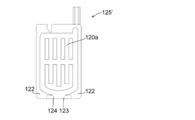
- FIG. 1 is a schematic perspective view of a container product using a sheet material container according to a preferred embodiment of the present invention.
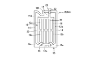
- Fig.2 (a) is a schematic front view of the container product using the sheet material container according to a preferred embodiment of the present invention before the external communication port is sealed.
- FIG. 2B is a schematic rear view of a container product using the sheet material container according to a preferred embodiment of the present invention before the external communication port is sealed.
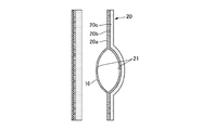
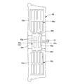
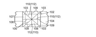
- FIG. 3 is a schematic perspective view of a container product using a sheet material container according to a preferred embodiment of the present invention, as viewed from the bottom side, in a state before the external communication port is sealed.
- FIG. 4A is a schematic cross-sectional view taken along the line AA of FIG.
- FIG. 4B is a schematic cross-sectional view illustrating another embodiment in which a fluid is enclosed in a non-adhesive region to form a filler encapsulating portion.
- FIG. 4C is a schematic cross-sectional view illustrating another mode in which a fluid is enclosed in a non-adhesive region to form a filler enclosing portion.
- FIG. 4D is a schematic cross-sectional view illustrating another layer configuration of the sheet material provided with the non-adhesive region.
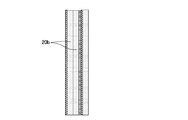
- FIG. 5 is a front view of a container sheet material used for a sheet material container according to a preferred embodiment of the present invention before commercialization.
- FIG. 6A is a schematic front view of a container product using a sheet material container according to another embodiment.
- FIG. 6B is a schematic perspective view of a container product using the sheet material container of another embodiment as viewed from the bottom surface side.
- FIG.6 (c) is an expansion
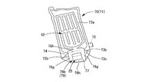
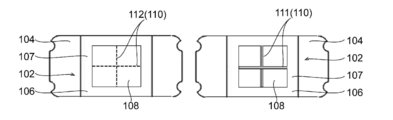
- FIG. 7A is a schematic perspective view of a container product using the sheet material container of another embodiment as viewed from the bottom surface side.
- FIG.7 (b) is an expansion
- FIG.8 (a) is the schematic perspective view which looked at the container product using the sheet
- FIG.8 (b) is an expansion
- Fig.9 (a) is the schematic perspective view which looked at the container product using the sheet
- FIG. 9B is a developed front view of the container sheet material used for the sheet material container according to another embodiment.
- FIG. 10 is a schematic perspective view of a container product using the sheet material container of another embodiment as viewed from the bottom surface side.
- FIG. 11 is a schematic perspective view of a container product using the sheet material container of another embodiment as viewed from the bottom surface side.
- FIG. 10 is a schematic perspective view of a container product using the sheet material container of another embodiment as viewed from the bottom surface side.
- FIG. 12 is a schematic perspective view of a container product using the sheet material container of another embodiment as viewed from the bottom surface side.
- FIG. 13 is a front view illustrating another form of the sheet material container.
- FIG. 14 is a front view illustrating another form of the sheet material container.
- FIG. 15 is a front view illustrating another form of the sheet material container.
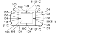
- FIG. 16A is a bottom view of a sheet material container illustrating another form of the leg forming portion.
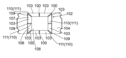
- FIG. 16B is a bottom view of a sheet material container illustrating another form of the leg forming portion.
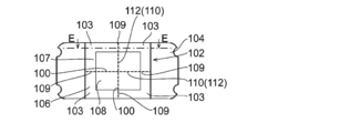
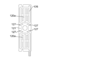
- FIG. 17A is a plan view of a bottom sheet illustrating another form of the leg forming portion.
- FIG. 17B is a schematic cross-sectional view taken along the line BB in FIG. FIG.
- FIG. 17C is a plan view of a bottom sheet illustrating another form of the leg forming portion.
- FIG. 17D is a plan view of a bottom sheet illustrating another form of the leg forming portion.
- FIG. 17E is a plan view of a bottom sheet illustrating another form of the leg forming portion.
- FIG. 17F is a plan view of a bottom sheet illustrating another form of the leg forming portion.
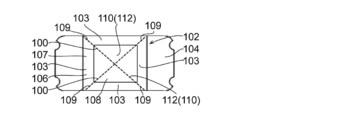
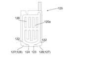
- FIG. 18A is a plan view of a bottom sheet illustrating another form of the leg forming portion.
- FIG. 18B is a schematic cross-sectional view taken along the line CC of FIG.
- FIG. 18C is a plan view of a bottom sheet illustrating another form of the leg forming portion.
- FIG. 18A is a plan view of a bottom sheet illustrating another form of the leg forming portion.
- FIG. 18B is a schematic cross-sectional view taken along the line CC of FIG.
- FIG. 18C is a plan view of a bottom sheet illustrating another
- FIG. 18D is a plan view of a bottom sheet illustrating another form of the leg forming portion.
- FIG. 18E is a plan view of a bottom sheet illustrating another form of the leg forming portion.
- FIG. 19A is a plan view of a bottom sheet illustrating another form of the leg forming portion.
- FIG. 19B is a schematic cross-sectional view along DD in FIG.
- FIG. 19C is a plan view of a bottom sheet illustrating another form of the leg forming portion.
- FIG. 19D is a plan view of a bottom sheet illustrating another form of the leg forming portion.
- FIG. 19E is a plan view of a bottom sheet illustrating another form of the leg forming portion.
- FIG. 20A is a plan view of a bottom sheet illustrating another form of the leg forming portion.
- FIG. 20B is a schematic cross-sectional view taken along line EE in FIG.
- FIG. 20C is a plan view of a bottom sheet illustrating another form of the leg forming portion.
- FIG. 20D is a plan view of a bottom sheet illustrating another form of the leg forming portion.
- FIG. 20E is a plan view of a bottom sheet illustrating another form of the leg forming portion.
- FIG. 21A is a plan view of a bottom sheet illustrating another form of the leg forming portion.
- FIG. 21B is a plan view of a bottom sheet illustrating another form of the leg forming portion.
- FIG. 21C is a plan view of a bottom sheet illustrating another form of the leg forming portion.
- FIG. 21A is a plan view of a bottom sheet illustrating another form of the leg forming portion.
- FIG. 21B is a plan view of a bottom sheet illustrating another form of the leg forming portion.
- FIG. 21C is a plan view of a bottom sheet
- FIG. 21D is a plan view of a bottom sheet illustrating another form of the leg forming portion.
- FIG. 22A is a plan view of a bottom sheet illustrating another form of the leg forming portion.
- FIG. 22B is a schematic cross-sectional view taken along the line FF in FIG.
- FIG. 22C is a plan view of a bottom sheet illustrating another form of the leg forming portion.
- FIG. 23A is a side view illustrating another form of the sheet material container.
- FIG. 23B is a developed front view of the container sheet material used for the sheet material container of FIG.
- FIG. 23 (c) is a schematic front view of the sheet material container of FIG. 23 (a).
- FIG. 24A is a side view illustrating another form of the sheet material container.
- FIG. 24B is a schematic front view of the sheet material container of FIG.
- an independent air chamber that is a reinforcing filler enclosing portion is provided only at the joint portion of the peripheral portion of the front sheet portion or the gusset portion sheet portion where the sealant layer is sealed and bonded by heat sealing. Since it cannot be formed, it is difficult to reinforce parts other than these joint parts by an independent air chamber or to increase rigidity.
- the present invention can improve the three-dimensional shape retaining property of the container, increase the drop strength, or improve the three-dimensional formability from the container sheet material, regardless of the amount of the contents, by the filler enclosure part.
- the present invention relates to a sheet material container that can be used, a method for producing the sheet material container, and a sheet material for containers used in the sheet material container.
- the present invention is a sheet material container comprising a body portion formed of a sheet material having a plurality of film layers, and a bottom portion disposed to face the placement surface, wherein the body portion is configured.
- seat which is provided is equipped with the junction part by which sheet
- the bottom sheet constituting the bottom portion is provided with a non-adhesive region between the plurality of film layers, and the non-adhesive region is filled with a filler to form a bottom filler encapsulating portion. ing.
- the bottom filler enclosing portion extends in an annular shape so as to surround the non-encapsulating portion of the bottom sheet, and forms at least three protruding leg portions that are placed on the placement surface and allow the container to stand on its own. .
- the protruding leg protrudes closer to the placement surface than the other part of the bottom filler encapsulating part by a leg forming part provided on the bottom.
- the present invention is a method for manufacturing the sheet material container, wherein the non-adhesive region forms a raw material of the sheet material provided on the bottom sheet, and individual sheet material containers of the raw material, The step of joining the peripheral portions of the sheet materials of the corresponding parts, the step of cutting the joined original fabric into a predetermined dimension, and filling the non-adhesive region with a filler to form the bottom filler filling portion The process to do is included.
- the present invention is a container product using the sheet material container, and the contents are accommodated in an accommodating part surrounded by the body part and the bottom part of the sheet material container.
- the present invention is a sheet material for a container which is used for the sheet material container and is formed using a sheet material having a plurality of film layers, and is formed on a body sheet and a peripheral portion of the body sheet.
- the bottom sheet is provided with a fold for folding, and is folded and overlapped flatly via the fold for folding.
- the bottom sheet is provided with a non-adhesive region in which a filler is enclosed between the plurality of film layers.
- the present invention is a method for manufacturing a container sheet material, wherein the non-adhesive region forms a raw sheet of the sheet material provided on the bottom sheet, and the individual container sheets of the original sheet A step of joining the peripheral portions of the sheet materials corresponding to the material, and a step of cutting the joined original fabric into predetermined dimensions.
- a sheet material container 10 according to a preferred embodiment of the present invention shown in FIGS. 1 to 3 contains a liquid detergent as a content liquid, for example, and is preferably a bag-shaped container product 11 similar to a standing pouch. It becomes.
- the sheet material container 10 of the present embodiment is formed using a thin sheet material 20 made of a synthetic resin having flexibility and rich in flexibility.
- the sheet material container 10 of the present embodiment includes a trunk sheet 12 (12a, 12a) that constitutes the trunk 12, and a bottom sheet 12b that constitutes the bottom 25, and the trunk sheet 12a, the bottom sheet 12b, Between the film layers of the sheet material in which a plurality of film layers are laminated, filler-encapsulating portions 16a and 16b, which are preferably formed by encapsulating the filler, are provided.
- the filler enclosing portion 16b By providing the filler enclosing portion 16b on the bottom sheet 12b, the bottom portion 25 arranged to face the placement surface can be effectively reinforced, the drop strength can be increased, or the amount of contents can be small.
- the three-dimensional holding property of the sheet material container 10 can be improved, and the rigidity of the mounting portion 17 for allowing the container to be self-supported by the filler enclosing portion 16b can be increased, thereby improving the self-supporting stability. Further, by providing the filler encapsulating portion 16a in the trunk sheet 12a, even when the amount of contents is small due to the combined use with the filler encapsulating portion 16b provided in the bottom sheet 12b, the trunk portion 12 is also provided. Further, it is possible to further enhance the three-dimensional holding property of the accommodating portion 12 surrounded by the bottom portion 25 and to have a certain elasticity and rigidity with respect to the compressive strength when the body portion 12 is gripped. Independence stability can be improved.
- the sheet material container 10 of this embodiment is opposite to the trunk
- drum 11 comprised by the sheet material 20 which has several film layer 20a, 20b, 20c (refer Fig.4 (a)), and a mounting surface.
- the body sheet 12a constituting the body part 11 is provided with a joining part 14 in which sheet materials are joined to each other at the peripheral part, and constitutes the bottom part 25.
- the bottom sheet 12b is provided with a non-adhesive region 21 between the plurality of film layers 20a, 20b, and 20c. By filling the non-adhesive region 21 with a filler, the bottom filler encapsulating portion 16b is formed. Is formed.
- the sheet material container 10 of the present embodiment is a bag-shaped container formed using the sheet material 20 formed by laminating a plurality of film layers 20a, 20b, and 20c (see FIG. 4A). And a body sheet 12a that forms a container that can store contents such as content liquid on the inside, and a joint part 14 that is formed by joining sheet materials to the peripheral part of the body sheet 12a, And a bottom sheet 12b.
- the bottom sheet 12b is preferably formed with a fold 13c for folding, and the contents are accommodated, for example, inside the accommodating portion 12 from a state where the fold 13c is folded and folded over the fold 13c for folding.
- the non-adhesive region 21 is filled with a filler and the bottom filler filling portion 16b is formed to expand, and the container 10 is placed in a line contact or surface contact with the placement surface to be self-supporting.
- the mounting portion 17 is formed.
- a non-adhesive region 21 is provided between the plurality of film layers 20a, 20b, and 20c constituting the sheet material 20 in at least the bottom sheet 12b, and the non-adhesive region 21 is preferably filled with air or water as a filler.
- a bottom filler encapsulating portion 16 b for reinforcement is formed by inflating the non-adhesive region 21 with the encapsulating filler as shown in FIG. 3.
- the accommodating portion 12 includes a pair of front and rear body sheets 12 a, and these body section sheets 12 a include a plurality of sheets constituting the sheet material 20.
- a non-adhesive region 21 provided between the film layers 20a, 20b, and 20c is preferably filled with a fluid such as air or water as a filler to form a front portion filler encapsulating portion 16a.
- the non-adhesion region 21 provided in the body sheet 12a for forming the front portion filler encapsulating portion 16a communicates with the non-adhesion region 21 for forming the bottom filler encapsulating portion 16b in the bottom sheet 12b.
- the sheet material container 10 includes the pair of front and rear front sheets 13a and 13a by the sheet material 20 via the peripheral portions of the front and rear front sheets 13a and 13a and the folding fold 13c.
- a bag-like container is formed by heat-sealing the peripheral portion of the bottom gusset portion sheet 13b, which can be folded inwardly, as a joining portion 14, for example.
- a portion of the pair of front and rear front sheets 13a and 13a surrounded by the joint portion 14 is a pair of front and rear body sheets 12a and 12a of the accommodating portion seat portion 12, and the joint portion 14 of the bottom gusset portion sheet 13b.
- the portion surrounded by is the bottom sheet 12b of the accommodating section sheet portion 12.
- heat sealing in this specification is not limited to heat sealing with a heated heat seal bar or roll, but includes all heat sealing capable of heat sealing a joint, such as ultrasonic sealing and high frequency sealing. means.
- the joining part 14 can be formed by, for example, bonding the sheet materials 20 together with an adhesive, in addition to being formed by heat-sealing the back surfaces of the sheet materials 20.
- the non-adhesive region 21 provided on the body sheet (body sheet) 12a, 12a and the bottom sheet 12b has an innermost sealant film layer 20c described later and an intermediate layer. It is formed between the layers of the barrier film layer 20b.
- the interlayer of these film layers 20b and 20c is bonded using a laminating adhesive (not shown), and the laminating adhesive is applied to the sealant film layer 20c or the barrier film layer 20b in a coating pattern including the non-adhesive region 21.
- the non-adhesive region 21 can be formed in a desired shape.
- the non-adhesive region 21 is formed by attaching at least one film layer 20a, 20b, 20c corresponding to the non-adhesive region 21 when the layers of the plurality of film layers 20a, 20b, 20c are bonded using a laminate adhesive.
- a non-adhesion treatment By applying a non-adhesion treatment to the surface, the non-adhesive region 21 can be formed in a desired shape.
- the non-adhesion treatment can be easily performed by applying a non-adhesive (a paste-killing agent) to a portion corresponding to the non-adhesion region 21 to obtain a paste-killed state. Any paste remover can be used as long as it can prevent adhesion of the pressure-sensitive adhesive layer.
- adhesion includes adhesion.
- the sheet material 20 constituting the pair of front and rear front sheet 13a, 13a and bottom gusset sheet 13b includes, for example, the outermost base film layer 20a,
- the sheet material has a three-layer structure in which an innermost sealant film layer 20c and an intermediate barrier film layer 20b sandwiched therebetween are laminated.
- the non-adhesive region 21 is formed between the innermost sealant film layer 20c and the intermediate barrier film layer 20b.
- the sheet material 20 constituting the pair of front and rear front sheets 13a and 13a and the bottom gusset section sheet 13b can form a plurality of barrier film layers 20b as an intermediate layer. .
- the non-adhesion region 21 can also be formed between the interlayer barrier film layers 20b.
- an outer layer composed of ONy 15 ⁇ m / adhesive layer / VM-PET 12 ⁇ m / (non-adhesive region) / adhesive layer / VM-ONy 15 ⁇ m / adhesive layer / LLDPE 40 ⁇ m (innermost layer) Can be mentioned.
- ONy means stretched nylon
- VM-ONy means stretched nylon with metal vapor deposition such as aluminum vapor deposition stretched nylon
- VM-PET means metal vapor deposited polyethylene terephthalate such as aluminum vapor deposition polyethylene terephthalate.
- seat material 20 which comprises a pair of front part sheet
- seat 13b is an interlayer of the base film 20a and the intermediate
- a non-adhesive region 21 may be formed.
- the sheet material 20 having such a layer configuration for example, a material composed of inorganic vapor-deposited PET 12 ⁇ m / (non-adhesive region) / adhesive layer / VM-PET 12 ⁇ m / adhesive layer / LLDPE 40 ⁇ m (innermost layer) from the outer layer can be exemplified.
- inorganic vapor deposition PET is PET by which alumina, a silicon oxide, etc. were vapor-deposited, for example.
- the sheet material 20 constituting the pair of front and rear front sheet 13a, 13a and bottom gusset part sheet 13b is used when the means for bonding between the films includes fusion such as thermal fusion or ultrasonic fusion.
- the intermediate barrier film layer 20 b has two sealant layers, and the non-adhesive region 21 is provided between these two sealant layers. May be formed.
- the sheet material 20 having such a layer structure for example, ONy 15 ⁇ m / adhesive layer / VM-PET 12 ⁇ m / adhesive layer / LLDPE 40 ⁇ m / (non-adhesive region) / LLDPE 40 ⁇ m / adhesive layer / VM-PET 12 ⁇ m / adhesive layer / ONy 15 ⁇ m /
- An adhesive layer / LLDPE of 40 ⁇ m (innermost layer) can be mentioned.
- the bonding with the adhesive will be described with reference to FIG. 4A, taking as an example the case where the non-adhesive region 21 is formed between the innermost sealant film layer 20c and the intermediate barrier film layer 20b.
- the non-adhesion region 21 may be provided between the interlayer barrier film layer 20b or between the barrier film layer 20b and the base film layer 20a.
- the outermost substrate film layer 20a is made of, for example, polyester such as polyethylene terephthalate (PET), polyethylene naphthalate (PEN), polybutylene terephthalate (PBT), polyethylene (PE), polypropylene (PP), polystyrene (PS). ), Or a stretched or unstretched film such as polyamide (PA) such as nylon-6 or nylon-66.
- polyester such as polyethylene terephthalate (PET), polyethylene naphthalate (PEN), polybutylene terephthalate (PBT), polyethylene (PE), polypropylene (PP), polystyrene (PS).
- PET polyethylene terephthalate
- PEN polyethylene naphthalate
- PBT polybutylene terephthalate
- PE polyethylene
- PP polypropylene
- PS polystyrene
- PA polyamide
- the thickness of the base film layer 20a is, for example, preferably 3 to 200 ⁇ m, more preferably 3 to 100 ⁇ m, and further preferably 6 to 30 ⁇ m.
- the innermost sealant film layer 20c includes, for example, a low density polyethylene resin (LDPE), a medium density polyethylene resin (MDPE), a high density polyethylene resin (HDPE), a linear low density polyethylene resin (L-LDPE), and a polypropylene resin. It can be formed using (PP) or the like.
- LDPE low density polyethylene resin
- MDPE medium density polyethylene resin
- HDPE high density polyethylene resin
- L-LDPE linear low density polyethylene resin
- PP linear low density polyethylene resin
- the thickness of the innermost sealant film layer 20c is, for example, preferably 15 to 200 ⁇ m, more preferably 20 to 180 ⁇ m, and even more preferably 30 to 170 ⁇ m.
- the intermediate barrier film layer 20b is formed using, for example, an aluminum vapor-deposited film, an ethylene-vinyl alcohol copolymer (EVOH), an aluminum foil, polyvinylidene chloride (PVDC), a PVDC coat film, a ceramic vapor-deposited film, or the like. be able to.
- the intermediate barrier film layer 20b is formed of a low-density polyethylene resin (LDPE) layer, a linear low-density, when the means for forming an adhesive portion around the non-adhesive region 21 of the sheet material 20 is fusion.
- LDPE low-density polyethylene resin
- L-LDPE polyethylene resin
- the thickness of the barrier film layer 20b is, for example, preferably 3 to 100 ⁇ m, more preferably 3 to 50 ⁇ m, and even more preferably 5 to 25 ⁇ m.
- the thickness of the barrier film layer 20b is preferably 80 ⁇ m to 200 ⁇ m, for example, The thickness is preferably 180 ⁇ m, and preferably 100 to 160 ⁇ m.
- film layers 20a, 20b, and 20c are easily bonded in a state of being integrally laminated by using a known laminating adhesive, for example, by a known laminating method such as dry lamination, non-solvent dry lamination, hot melt lamination, or the like.
- a known laminating method such as dry lamination, non-solvent dry lamination, hot melt lamination, or the like.
- a non-adhesive region can be formed (an adhesive portion is formed by a convex portion and a non-adhesive region is formed by a concave portion). It is also possible to form a non-adhesive region by sandwiching a sheet (PET, etc.) that is not welded to the sealant cut into the shape of the non-adhesive region, and sandwiching it between the inner and outer films and pressing with a flat mold It is.
- adhesion in an adhesion region other than the non-adhesion region 21 includes heat fusion, fusion using ultrasonic waves or laser, pressure bonding, and the like in addition to adhesion by an adhesive.
- the bonding method is preferably bonding with an adhesive from the viewpoint of thinning the layer structure and the degree of freedom of the coating pattern, and fusion is preferable from the viewpoint of obtaining a certain strength regardless of the material of the adhesive.
- the adhesion between the innermost sealant film layer 20c and the intermediate barrier film layer 20b in the pair of front and rear front sheet 13a, 13a and bottom gusset part sheet 13b is as described above.
- it is performed by applying a laminating adhesive on the surface of the sealant film layer 20c and the barrier film layer 20b with a predetermined application pattern including the non-adhesive region 21.
- a laminating adhesive on the surface of the sealant film layer 20c and the barrier film layer 20b with a predetermined application pattern including the non-adhesive region 21.
- a non-adhesive region 21 for forming a reinforcing front portion filler encapsulating portion 16a including a lateral encapsulating portion 16c, a longitudinal enclosing portion 16d, and a bottom curved encapsulating portion 16e is included in the rib-shaped encapsulation. It is formed between the sealant film layer 20c and the barrier film layer 20b with the portions 16c, 16d, and 16e communicating with each other. Further, in the bottom gusset portion sheet 13b, the bottom sheet portion 12b surrounded by the joint portion 14 at the peripheral portion is filled with a bottom filling material for reinforcement including a cross encapsulation portion 16g and a communication encapsulation portion 16h, as shown in FIG.
- the sealant film layer in a state in which the non-adhesive region 21 for forming the portion 16b communicates with the front portion filler encapsulating portion 16a of the pair of front and rear body sheets 12a and 12a via the connecting portion filler encapsulating portion 16f. It is formed between the layers between 20c and the barrier film layer 20b.
- a connecting portion filler enclosing portion 16f that communicates the front portion filler enclosing portion 16a provided in 12a and the bottom filler enclosing portion 16b provided in the bottom sheet portion 12b is provided at the bottom portion of the sheet material container 10. It can be easily provided in a state where the provided joint portion 14 is crossed.
- an external communication port 22 is provided to open the joint portion 14 in the upper side portion of the sheet material container 10 and supply a filler to the inside of the non-adhesive region 21 (FIG. 1). 2 (a), FIG. 2 (b), FIG. 3, and FIG. 5).
- the external communication port 22 is formed to open to the joint portion 14 on the upper side portion of one front portion sheet 13a on the front side of the pair of front and rear front portion sheets 13a and 13a.
- the external communication port 22 covers the inner wall surface of the external communication port 22 and is bonded with a seal bonding piece 23 so that the external communication port 22 can be easily sealed after the fluid is injected.
- the external communication port 22 has one inner wall surface facing the wall surface formed by the sealant film layer 20c and the other inner wall surface formed by the barrier film layer 20b (see FIG. 4).
- after filling the filler by covering the other inner wall surface by the barrier film layer 20b and adhering the seal joining piece whose one inner wall surface is a sealant film layer By heat-sealing the upper side portion where the communication port 22 is provided, the external communication port 22 can be easily sealed.
- the seal joining piece 23 can be provided in a state of protruding upward from the external communication port 22, and the protruding portion is removed after the external communication port 22 is sealed by heat sealing.
- the protruding portion of the seal joining piece 23 may be left as it is without being removed.
- a check valve made of a resin (for example, polyethylene resin) that can be preferably heat-sealed between the adhered seal joining piece 23 and one inner wall surface of the sealant film layer 20c at the external communication port 22. (Not shown) can also be sandwiched in close contact. By sandwiching the check valve, it is effectively avoided that the filled material leaks from the non-adhesive region 21 through the external communication port 22 until the external communication port 22 is sealed. It becomes possible to do.
- the check valve is heat-sealed in a state in which the check valve is sandwiched, so that the check valve is deformed so as to be crushed and the flow path of the filler is closed, so that the external communication port 22 can be easily sealed. .
- the external communication port 22 can be sealed (sealed) by heat sealing, and can be sealed by using, for example, an air valve for a beach ball instead of the seal joining piece 23. Further, the external communication port 22 can be sealed with an adhesive.
- the non-adhesive region 21 is filled and the filler encapsulating portions 16a, 16b, and 16f (the front portion filler encapsulating portion 16a, the bottom filler encapsulating portion 16b, and the connecting portion filler encapsulating portion 16f).
- a fluid selected from gases such as nitrogen and air, water, aqueous solutions, and oils can be preferably used.
- a granular material, resin, a foaming material, etc. can also be used.
- the foam material a material that foams when irradiated with ultraviolet rays, such as a UV curable foam gasket, can also be used.
- the UV curable foam gasket After the UV curable foam gasket is sealed in the non-adhesive region 21, it is foamed and cured by irradiating ultraviolet rays from the outside of the container 10.
- Bulge-like or rib-like filler enclosing portions 16a, 16b, 16f are formed.
- the filler encapsulating portions 16a, 16b, and 16f can be formed by appropriately mixing the above-described fluid, powder, and the like and filling the non-adhesion region 21.
- gases such as nitrogen and air are more preferable from the viewpoint of weight reduction.
- the interlayer between the innermost sealant film layer 20c and the intermediate barrier film layer 20b is applied in a predetermined application pattern including the non-adhesive region 21.
- the non-adhesive region 21 corresponding to the plurality of sheet material containers 10 is arranged continuously in the flow direction (Machine Direction) of the raw fabric manufacturing apparatus by adhering via the laminated adhesive.
- the original fabric portion of the bottom gusset portion sheet 13b is placed inside the bottom portion between the original fabric portions of the pair of front surface sheets 13a and 13a that are overlapped in the bag making apparatus.
- the bag In a state where the cross section is folded into an M shape, the bag is fed in the flow direction of the bag making apparatus. Further, in the portion corresponding to the individual sheet material containers 10 of the fed sheet material 20, the peripheral portions of the sheets 13 a, 13 a, 13 b of the individual sheet material containers 10 serve as the inlet for the content liquid. Joining by heat sealing, for example, leaving a portion. Furthermore, the heat-sealed original fabric is cut at the joints 14 between the individual sheet material containers 10 provided in series. As a result, the sheet material container 10 before the filler is enclosed in the non-adhesive region 21 as shown in FIG. 5 is rectangular (including a substantially rectangular shape) in a state of being flatly folded as the container sheet material 18. ) To have a front shape.
- the container sheet material 18 used for the sheet material container 10 of the present embodiment and formed using the sheet material 20 having the plurality of film layers 20a, 20b, and 20c has a non-adhesive region 21 at least a bottom sheet 12b.
- a step of forming the raw material of the sheet material 20 provided on the pair of body sheets 12a, 12a and the bottom sheet 12b), the peripheral edge of the portion corresponding to the individual sheet material 18 for the container It can be manufactured by a manufacturing method including a step of bonding parts and a step of cutting the bonded raw material into a predetermined size so as to become individual container sheet materials 18.
- the manufactured container sheet material 18 is provided with a non-adhesive region 21 between a plurality of film layers 20a, 20b, and 20c constituting the sheet material 20, and a filler is enclosed in the non-adhesive region 21.
- a filler is enclosed in the non-adhesive region 21.
- a step of joining the peripheral portions of the portions corresponding to the individual sheet material containers 10 of the original fabric, a step of cutting the joined original fabric into a predetermined size, and a non-adhesive region 21 with a filler By the manufacturing method including the step of forming the bottom filler enclosure portion 16b for reinforcement (in this embodiment, the front portion filler enclosure portion 16a, the bottom filler enclosure portion 16b, and the connection portion filler enclosure portion 16f). Can be manufactured.
- the sheet material container 10 having the above-described configuration is, for example, a product in a state where the sheet material 18 for a container before the filler is sealed in the non-adhesive region 21 is folded flat as illustrated in FIG. It is carried into the manufacturing factory. As a result, a large number of container sheet materials 18 before being filled with the contents including the contents liquid can be efficiently carried in with the conveying volume being reduced without being bulky.
- the contents are stored in the storage portion of the sheet material container 10, the filler is enclosed in the non-adhesive region 21, and the bottom filler filling portion 16 b for reinforcement (in this embodiment, the front portion is filled).
- the bag-shaped container product 11 can be easily manufactured by the manufacturing method including the steps of forming the material sealing portion 16a, the bottom filler sealing portion 16b, and the connection portion filler sealing portion 16f).
- the loaded container sheet material 18 is released from a flatly folded state, and the non-adhesive region 21 is filled with a filler via the external communication port 22.
- the sheet is preferably formed into a three-dimensional shape with the bottom gusset portion sheet 13b as the bottom by forming bulge-like or rib-like filler enclosing portions 16a, 16b, and 16f by sealing.
- a material container 10 is formed. Thereafter, the liquid detergent, which is the content liquid, is injected into the accommodating portion 12 using the portion of the upper side portion of the pair of front portion sheets 13a, 13a that is left without heat sealing as an injection port.
- the portion of the inlet is preferably joined by heat sealing, and the portion of the seal joint 23 that protrudes upward from the external communication port 22 is cut as necessary. Remove.
- the container product 11 containing the liquid detergent in the sheet material container 10 places the placement portion 17 (see FIG. 3) formed on the bottom sheet 12b on the placement surface. It will be commercialized in a state where it can stand on its own.
- the container product 11 injects the liquid detergent into the container sheet material 18 through the injection port, and then encloses the filler in the non-adhesive region 21 through the external communication port 22, thereby filling the filler enclosing unit 16.
- the container product 11 can be commercialized.
- the filler is enclosed in the non-adhesive region 21 through the external communication port 22, so that the filler encapsulating portion 16 is formed.
- the container product 11 can be commercialized.
- the filler material is enclosed in the non-adhesive region 21 via the external communication port 22 to form the filler material sealing portion 16 to form the sheet material container 10, and then the sheet material via the inlet port.
- the front side and the back side of the body sheet 12a that forms the storage part in which the content liquid is stored inside that is, the body part 12
- Each of the pair of front and rear body sheets 12a, 12a is provided with a rib-like reinforcing front portion filler enclosing portion 16a, which is preferably elongated in a linear shape.
- the bottom sheet 12b constituting the accommodating portion 12 is provided with a bottom filler encapsulating portion 16b for reinforcement, preferably in the form of a rib, for example, extending in a long and thin line shape (see FIG. 3).
- the front portion filler encapsulating portion 16a provided on the body sheets 12a and 12a and the bottom filler enclosing portion 16b provided on the bottom sheet 12b are provided at the joint portion 14 at the bottom portion of the sheet material container 10.
- the connecting portion filling material sealing portion 16f is in communication with each other.
- the filler encapsulating portions 16a, 16b, and 16f extending in an elongated line shape are enclosing portions that are continuously provided with a width of, for example, about 3 to 50 mm, and are enclosing portions that extend continuously in a straight line.
- an enclosing portion continuously extending in various other elongated shapes such as a curved shape, a corrugated shape, and a crank shape is also included.
- a filler enclosing portion 24 having a wide width and protruding in a dome shape, or a spherical shape or the like alone or in combination as appropriate see FIG. 13
- the sheet material container 10 has a three-dimensional shape in which the filler is enclosed and the filler enclosure portions 16a, 16b, and 16f are expanded, or the contents are sufficiently accommodated.
- a region corresponding to a corner portion in the cross section formed in the body sheet 12a, 12a in the case of a three-dimensional shape is provided with a bulging region due to the filler enclosing portion 16a.
- the corners in the transverse section formed on the trunk sheets 12a, 12a are formed by ridges standing from the bottom side of the trunk sheets 12a, 12a or curved corners, and correspond to such ridge lines or corners. It is preferable from the viewpoint of drop strength and shape retention that the filler encapsulating portion 16a is formed in the region.
- the reinforcing front portion filler enclosing portion 16a provided in each of the pair of front and rear body sheets 12a, 12a extends in the lateral direction.
- the body sheet 12a is configured to include a bottom curve enclosing portion 16e that is arranged so as to be curved along the bottom of the body sheet 12a.
- the three vertical enclosures 16d sandwiched between the pair of vertical enclosures 16d on both sides are connected to the bottom curved enclosure 16e (communication). ) Without being separated from the bottom curve enclosing portion 16e.
- the separated portion is bent by the weight of the contents, and the bottom surface of the container product is further easily expanded, so that the self-supporting stability is further improved.
- the front-side body sheet 12a of the pair of front and rear body sheets 12a, 12a extends upward from, for example, the upper end of the second vertical enclosure 16d from the right, and is connected to the communication port.
- a portion 16i is formed.
- a portion of the upper portion of the communication port connection enclosing portion 16 i that overlaps the joint portion 14 on the upper side portion of the front sheet 13 a is an external communication port 22.
- the external communication port 22 is preferably formed after injecting a fluid such as air or water as a filler into the non-adhesive region 21 to inflate the filler enclosure portions 16a, 16b, and 16f.
- the external communication port 22 can be sealed by using, for example, an adhesive or a check valve, or by folding the external communication port 22 in addition to heat sealing.
- the reinforcing front portion filler encapsulating portion 16a provided in the trunk sheet 12a, 12a includes a lateral enclosing portion 16c formed extending in the lateral direction, whereby the container product 11
- a lateral enclosing portion 16c formed extending in the lateral direction, whereby the container product 11
- the vertical enclosing portion 16d formed to extend in the vertical direction, it is possible to effectively increase the strength and rigidity against the vertical load applied to the container product 11. At the same time, it becomes possible to improve the gripping property of the body portion 12.
- the reinforcing front portion filler enclosure portion 16a for reinforcement includes a transverse enclosure portion 16c formed by extending in the transverse direction and a longitudinal enclosure portion 16d formed by extending in the longitudinal direction.
- the accommodating part is equipped with the bottom face sheet
- the contents are accommodated in the accommodating portion, or the filling material is enclosed in the non-adhesive region 21 to form the bottom filling material enclosing portion 16b, so that the mounting portion 17 is formed.
- a non-adhesive region 21 is provided between the plurality of film layers 20a, 20b, 20c constituting the sheet material 20 in the bottom sheet 12b (see FIG. 4), and a filler is provided in the non-adhesive region 21.
- the bottom filler encapsulating portion 16b is formed by the non-adhesive region 21 by being encapsulated.
- the bottom sheet 12b constituting the bottom portion 25 of the housing portion includes three cross-encapsulating portions 16g and a pair of communication rib portions 16h as the bottom filler encapsulating portion 16b for reinforcement.
- the filler enclosure part comprised by these is provided.
- the intersecting enclosing portion 16g is arranged so as to intersect the folding fold 13c of the bottom gusset portion sheet 13b, which is folded so as to have an M-shaped cross section inside the bottom portion of the pair of front portion sheets 13a, 13a, substantially perpendicularly.
- the communication rib portion 16h is disposed so that both end portions of the three intersecting rib portions 16g communicate with each other.
- the bottom sheet 12b is provided with the bottom filler encapsulating portion 16b, so that the strength and rigidity of the bottom sheet 12b can be effectively increased. Further, the bottom encapsulating portion 16g of the bottom filler encapsulating portion 16b is disposed so as to intersect substantially perpendicularly with the fold 13c of the bottom gusset portion sheet 13b, whereby the intersecting encapsulating portion 16g swells and is folded into the bottom surface. The bottom sheet 12b by the gusset portion sheet 13b can be smoothly guided so as to spread against the folds.
- the bottom sheet 12b is expanded, and the placement portions 17 formed on the bottom sheet 12b are three. It is possible to place the rectangular filler-shaped bottom filler encapsulating portion 16b having a substantial size by the cross enclosing portion 16g and the pair of communication rib portions 16h on the placement surface as a leg portion. As a result, the shape of the portion where the bottom sheet 12b is brought into contact with the placement surface can be stabilized, and the bag-like container product 11 can be made to stand up in a more stable state (see FIG. 1).
- the degree of freedom of selection of the shape and arrangement position of the reinforcing filler enclosures 16a, 16b, and 16f is improved, and the reinforcing filler enclosure part at any position of the container 10 is improved.
- the bottom sheet 12b is effectively reinforced by the bottom filler encapsulating portion 16b to improve the self-supporting stability by the placement portion 17 or the placement portion. 17 can be increased in rigidity.
- region 21 is provided between the several film layers 20a, 20b, 20c which comprise the sheet
- region 21 is provided. 1 to 3, the non-adhesive region 21 swelled by the encapsulated filler swells the reinforcing filler encapsulating portions 16 a, 16 b, and 16 f into the sheet material, as shown in FIGS. 1 to 3. It can be easily formed between 20 film layers 20a, 20b, 20c.
- a laminate adhesive coating pattern for adhering the layers of the plurality of film layers 20a, 20b, and 20c can be freely designed in an arbitrary shape and arrangement, so that not only the joint portion 14 but also a housing that is particularly easily deformed is accommodated.
- the non-adhesive region 21 can be easily provided in a desired shape and arrangement on the body sheet 12a, 12a and the bottom sheet 12b constituting the part. By filling the non-adhesive region 21 with a filler and forming the filler enclosing portions 16a, 16b, and 16f in a desired shape and arrangement, desired portions of the sheet material container 10 and the container product 11 can be efficiently obtained. It is possible to effectively reinforce and improve the rigidity.
- FIGS. 6A and 6B illustrate a sheet material container 60 and a container product 61 according to another embodiment of the present invention.
- the sheet material container 60 and the container product 61 of FIGS. 6A and 6B have the same configuration as the sheet material container 10 and the container product 11 of the above embodiment, but on the other hand, the bottom portion is filled.
- the shape and arrangement of the material enclosure 66b and the external communication port 62 are different from the shape and arrangement of the bottom filler enclosure 16b and the external communication port 22 in the above embodiment.
- the sheet material container and container product shown in FIGS. 6 (a) to 12 described later are portions in which the bottom filler enclosing portions 66b, 76b, 86b, and 96b are continuous from the front side to the back side of the body portion 12 facing each other.
- it is provided with a non-filler-filling portion in which no filler is enclosed, which is surrounded by non-adhesive regions forming bottom filler-filling portions 66b, 76b, 86b, 96b.
- Non-adhesive regions 79, 89, and 99b are provided surrounding the central adhesive region. More preferably, the bottom filler encapsulating portions 66b, 76b, 86b, 96b are formed along the periphery of the mounting portion (mounted region) mounted on the mounting surface, and more preferably the peripheral edge It is formed continuously along. By forming the bottom filler encapsulating portions 66b, 76b, 86b, and 96b in this manner, the rigidity of the bottom portion can be further increased, and the self-supporting stability and the three-dimensional shape retention by the bottom portion can be improved.
- the bottom filler enclosing portions 66b, 76b, 86b, and 96b are provided in the boundary region between the body sheet and the bottom sheet. Is preferred. That is, the boundary region between the body sheet and the bottom sheet corresponds to a corner of the sheet material container, and the filler enclosing portions 66b, 76b, 86b, and 96b are provided at the corner, whereby the sheet The leg portion of the material container is formed by the filler enclosing portions 66b, 76b, 86b, 96b, so that the drop strength and the self-supporting stability can be further improved.
- the boundary region between the trunk front sheet 12a and the bottom sheet 12b does not necessarily have to be a joint part by heat sealing, and the front sheet 12a and the bottom sheet 12 are not separate films, for example, but a single sheet.
- the film can be formed without using a heat-sealed joint.
- the sheet material container 60 and the container product 61 shown in FIG. 6 (c) are also shown in a developed front view of the container sheet material 68 used for the sheet material container 60.
- the bottom filler encapsulating portion 66b formed by encapsulating the filler in the non-adhesive region 69 includes three cross encapsulating portions 66g and a pair of communication rib portions 66h.
- the three intersecting enclosing portions 66g are provided in the bottom sheet 62b so as to intersect the folding fold 63c provided on the bottom gusset portion sheet 63b substantially perpendicularly and in parallel with each other.
- the pair of communication rib portions 66h that respectively connect the two end portions of the three intersecting enclosing portions 66g to each other are the bottom side portions on both side edges of the front and rear pair of front portion sheets 63a and 63a, and the bottom gusset portion sheet 63b.
- the two side edges are disposed and provided in a joint portion 64 joined by, for example, heat sealing.
- the external communication port 62 extends from the intersecting encapsulating portion 66g of the bottom filler encapsulating portion 66b along one side of the fold 63c of the bottom gusset portion sheet 63b and extends outward from the side portion of the bottom gusset portion sheet 63b. It is arranged and provided in a protruding state.
- the filler is enclosed in the non-adhesive region 69 to form the bottom filler enclosure portion 66b, or the contents are stored in the accommodation portion.
- the bottom sheet 62b is unfolded when an object is accommodated, and the mounting portion 67 formed on the bottom sheet 62b is mounted with a rectangular frame-shaped bottom filler encapsulating portion 66b of a considerable size as a leg portion. Since it can be mounted on the mounting surface, the same effects as the sheet material container 10 and the container product 11 of the above embodiment are exhibited.
- the communication rib portion 66h of the bottom surface portion filler enclosure portion 66b is formed at the bottom of the pair of front surface sheets 63a and 63a. It is provided with a considerable length along the joint portion 64 between the portion and the peripheral edge portions on both sides of the bottom gusset portion sheet 63b.
- an external communication port 62 is provided so as to extend from the bottom filler encapsulating portion 66b, and a bottom side portion of the pair of front portion sheets 63a and 63a and a peripheral portion on both sides of the bottom face gusset portion sheet 63b.
- a communication rib portion 66h of the bottom filler encapsulating portion 66b is provided with a considerable length. Accordingly, these communication rib portions 66h are used as connecting portions between the bottom filler encapsulating portion 66b and the front filler encapsulating portion 66a, so that the bottom filler encapsulating can be performed by a simple filling material enclosing process with a small pressure loss. It is possible to smoothly fill and fill the portion 66b and the front portion filling material enclosure 66a with the filling material.
- FIG. 7A also illustrates a sheet material container 70 and a container product 71 according to another embodiment of the present invention.
- the sheet material container 70 and the container product 71 of FIG. 7 (a) also have the same configuration as the sheet material container 10 and the container product 11 of the above embodiment, but on the other hand, the bottom filler enclosing unit 76b and The shape and arrangement of the external communication port 72 are different from the shapes and arrangement of the bottom filler encapsulating portion 16b and the external communication port 22 of the above embodiment.
- the bottom filler enclosure portion 76b formed by encapsulating the filler in the region 79 is formed to have a rectangular frame shape including a pair of intersecting enclosure portions 76g and a pair of communication rib portions 76h.
- the pair of intersecting enclosing portions 76g are provided in the bottom sheet 72b so as to intersect substantially perpendicularly with the fold 73c of the bottom gusset portion sheet 73b and to be parallel to each other.
- the pair of communication rib portions 76h that respectively connect the both end portions of the intersecting enclosure portion 76g are the bottom side portions of the both side edges of the pair of front and rear front surface sheets 73a and 73a and the both side edges of the bottom gusset portion sheet 73b.
- the external communication port 72 extends from the intersection enclosing portion 76g of the bottom filler encapsulating portion 76b along one side of the crease 73c of the bottom gusset portion sheet 73b and extends outward from the side portion of the bottom gusset portion sheet 73b. It is arranged and provided in a protruding state.
- the filler is enclosed in the non-adhesive region 79 to form the bottom filler enclosure portion 76b, or the contents are accommodated in the accommodation portion. Then, the bottom sheet 72b is unfolded, and the mounting portion 77 formed on the bottom sheet 72b is mounted on the mounting surface with the rectangular frame-shaped bottom filler enclosing portion 76b having a considerable size as a leg portion. Therefore, the same effect as the sheet material container 10 and the container product 11 of the above embodiment can be obtained.
- the communication rib portion 76h of the bottom filler encapsulating portion 76b includes a bottom side portion on both side edges of the pair of front portion sheets 73a and 73a, and Since it is provided with a considerable length along the joint portions 74 with both side edges of the bottom gusset portion sheet 73b, the same effects as the sheet material container 60 and the container product 61 of the other embodiments described above are obtained. Is done.
- the bottom filler encapsulating portion 76b has a rectangular frame shape including a pair of intersecting encapsulating portions 76g and a pair of communication rib portions 76h, the non-adhesive region 79 is filled with the filler to fill the bottom portion.
- the bottom sheet portion 72b can be easily expanded and more rigidity is imparted to the leg portion of the mounting portion 77 by the bottom filler enclosing portion 76b. Is possible.
- FIG. 8A also illustrates a sheet material container 80 and a container product 81 according to another embodiment of the present invention.
- the sheet material container 80 and the container product 81 of FIG. 8 (a) also have the same configuration as the sheet material container 10 and the container product 11 of the above embodiment, but on the other hand, the bottom filler enclosing portion 86b and The shape and arrangement of the external communication port 82 are different from the shapes and arrangement of the bottom filler encapsulating portion 16b and the external communication port 22 of the above embodiment.
- the bottom filler encapsulating portion 86b formed by encapsulating the filler in the region 89 has a pair of front and rear pair of front portion sheets 83a and 83a and a pair of sides on both sides where the peripheral portion of the bottom gusset portion sheet 83b is joined.
- the planar encapsulating portion 86k has a circular non-encapsulating portion 86j at the center.
- the external communication port 82 extends from the side portion of the rectangular planar enclosing portion 86k along one side of the fold 83c of the bottom gusset portion sheet 83b, and extends from the side portion of the bottom gusset portion sheet 83b. It is arranged and provided in a state of protruding outward. It is preferable that the non-encapsulating portion 86j in the central portion is composed of an adhesive portion where a plurality of film layers are bonded together.
- the filler is enclosed in the non-adhesive region 89 to form the bottom filler enclosure portion 86b, or the contents are accommodated in the accommodation portion.
- the bottom sheet 82b is unfolded, and the mounting portion 87 formed on the bottom sheet 82b can be mounted on the mounting surface with the rectangular planar encapsulating portion 86k having a considerable size as a leg portion. Therefore, the same effect as the sheet material container 10 and the container product 11 of the above embodiment is exhibited.
- the edge portions on both sides of the rectangular planar enclosing portion 86k are connected to the bottom side portions of the pair of front surface sheets 83a and 83a and the bottom gusset. Since it is provided with a considerable length along the joint portion 84 with the peripheral edge portions on both sides of the part sheet 83b, the same effects as the sheet material container 60 and the container product 61 of the other embodiments are obtained. Is done.
- the bottom filler encapsulating portion 86b is formed to include a rectangular planar encapsulating portion 86k that is continuously disposed so as to straddle the pair of joint portions 84 on both sides. It becomes possible to improve the self-supporting stability when the placement portion 87 is placed on the placement surface using the material enclosure portion 86b as a leg portion.
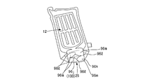
- FIG. 9A also illustrates a sheet material container 90 and a container product 91 according to another embodiment of the present invention.
- the sheet material container 90 and the container product 91 of FIG. 9 (a) also have the same configuration as the sheet material container 10 and the container product 11 of the above embodiment, but on the other hand, the bottom filler enclosing unit 96b and The shape and arrangement of the external communication port 92 are different from the shapes and arrangement of the bottom filler encapsulating portion 16b and the external communication port 22 of the above embodiment.
- the bottom filler encapsulating portion 96b formed by encapsulating the filler in the region 99 has a pair of both sides of the pair of front and rear front sheets 93a and 93a and the peripheral portion of the bottom gusset sheet 93b joined together. It is formed including a rectangular planar encapsulating portion 96k having a non-encapsulating portion 96j in the central portion, which is continuously disposed so as to straddle the joining portion 94.
- the planar encapsulating part 96k has a rhombus-shaped non-encapsulating part 96j at the center.
- the rhombus-shaped non-encapsulating portion 96j is arranged in a state in which the corner portions thereof are directed to the intermediate portions separated from the four corner portions of the rectangular shape in the four side portions of the rectangular planar encapsulating portion 96k. And it is provided.
- the external communication port 92 extends from the side portion of the rectangular planar enclosing portion 96k along one side of the fold 93c of the bottom gusset portion sheet 93b, and extends from the side portion of the bottom gusset portion sheet 93b. It is arranged and provided in a state of protruding outward.
- the filler is enclosed in the non-adhesive region 99 to form the bottom filler enclosure portion 96b, or the contents are accommodated in the accommodation portion.
- the bottom sheet portion 92b is unfolded, and the placement portion 97 formed on the bottom sheet portion 92b is placed on the placement surface with a rectangular planar encapsulating portion 96k having a considerable size as a leg portion. Therefore, the same effect as the sheet material container 10 and the container product 11 of the above embodiment can be obtained.
- the edge portions on both sides of the rectangular planar enclosing portion 96k are connected to the bottom side portions of the pair of front surface sheets 93a and 93a and the bottom surface gusset. Since it is provided with a considerable length along the joint portions 94 with the peripheral edge portions on both sides of the part sheet 93b, the same effects as the sheet material container 60 and the container product 61 of the other embodiments are obtained. Is done.
- the bottom filler encapsulating portion 96b is formed to include a rectangular planar encapsulating portion 96k that is continuously disposed so as to straddle the pair of joint portions 94 on both sides. It becomes possible to improve the self-supporting stability when the placement portion 97 is placed on the placement surface using the material enclosure portion 96b as a leg portion.
- the non-encapsulating portion 96j provided in the central portion of the rectangular planar encapsulating portion 96k preferably has a rhombus shape.
- the corner portions of the rectangular planar encapsulating portion 96k are arranged in a state of being directed toward an intermediate portion spaced from the four corner portions.
- the planar encapsulating portion 96k has an intermediate portion spaced from the four corners of the rectangular shape.
- a wrinkle portion 96l bent in a concave shape is formed from the corner portion of the non-encapsulating portion 96j toward the four sides of the rectangular shape.
- a wrinkle portion 96l that is bent into a concave shape is formed in an intermediate portion that is spaced apart from the four corners of the planar encapsulating portion 96k. Since the enclosing portion 96k bulges further downward as a convex portion (projecting leg portion), the convex portion on both sides of such a bulged ridge portion (wrinkle) 96l is defined as a projecting leg portion 96m, and the placing portion 97 Is placed on the placement surface, the sheet material container 90 and the container product 91 can be made to stand in a more stable state. That is, the non-encapsulating portion 96j functions as the leg forming portion 100 by guiding the non-encapsulating portion 96j so that wrinkles are formed in the planar encapsulating portion 96k.
- the non-encapsulating part 96j functioning as the leg forming part 100 which is disposed with the corners facing the middle part of the four sides of the planar encapsulating part 96k, has a rhombus shape. It is not always necessary.
- the non-encapsulating part 96j functioning as the leg part forming part 100 may have a substantially rhombus shape in which the four side parts are curved concavely toward the inside. Further, as shown in FIG.
- the non-encapsulating part 96j functioning as the leg part forming part 100 has three corners of the four sides of the rectangular encapsulating part 96k.
- three sides have a substantially triangular shape curved in a concave shape toward the inside. May be.
- the sheet material container 90 in FIG. 9A includes a body portion 12 and a mounting surface that are configured by the sheet material 20 having a plurality of film layers 20a, 20b, and 20c (see FIG. 4A).
- a body portion sheet 93a constituting the body portion 12 is provided with a joint portion 94 in which sheet materials are joined to each other at the peripheral portion,
- a non-adhesive region 99 is provided between the plurality of film layers 20a, 20b, and 20c on the bottom sheet 93b constituting the bottom portion 25.
- the non-adhesive region 99 is filled with a filler and forms a bottom filler encapsulating portion 96b.
- the bottom filler enclosing portion 96b extends in an annular shape surrounding the non-encapsulating portion 96j of the bottom sheet 93. And at least three (four in the present embodiment) projecting leg portions 96m that are placed on the placement surface to make the container 10 self-supporting, and form projecting leg portions 96m. Is protruded closer to the placement surface than the other part (saddle-like portion) of the bottom filler inclusion portion 96b by the non-encapsulation portion 96j functioning as the leg portion forming portion 100 of the placement portion 97.
- the placement portion 97 placed on the placement surface has at least three projecting leg portions 96m, thereby further improving the self-supporting stability when the sheet material container 90 is placed on the placement surface. It becomes possible to make it.
- the leg forming part 100 that forms at least three projecting leg parts 96m on the mounting part 97 is formed on the bottom part of the bottom filler encapsulating part 96b extending in an annular shape surrounding the non-encapsulating part 96j.
- This is a part provided with means for forming at least three protruding leg portions 96m on the bottom filler encapsulating portion 96b to generate irregularities and make contact with the mounting surface preferably in a point-like manner.
- the leg portion forming unit 100 includes a wrinkle guiding portion that guides the bottom filler encapsulating portion 96b so that a plurality of wrinkles 96l are formed. It may be formed by the convex part itself or the concave part itself provided by performing uneven processing.
- the filler encapsulating portion 96b extending in an annular shape surrounding the non-encapsulating portion 96j of the bottom sheet 93 does not necessarily need to be formed by the non-adhesive region 99 that is continuous in an annular shape.
- attached may be included in the part like "C shape" shape.
- the leg forming portion 100 that forms at least three projecting leg portions 96m on the mounting portion 97 has a non-adhesive region as viewed from the bottom as shown in FIGS. 16 (a) and 16 (b).
- 99 may be provided with a widened portion 101 whose width in the direction perpendicular to the extending direction is larger than other portions in 99.
- the widened portion 101 having a larger width bulges out to have a larger cross-sectional area than the other portions of the bottom filler enclosed portion 96b.
- the protruding portion 96m is formed so as to protrude from the other portion of the bottom filler encapsulating portion 96b extending in an annular shape surrounding the non-encapsulating portion 96j to the placement surface side. . Since the protruding leg portion 96m formed by the widened portion 101 is arranged as far as possible (in the direction of the outer edge of the bottom portion) as viewed from the bottom in the mounting portion 97, the self-supporting stability is improved. 96b is preferably shaped such that the widened portion 101 is formed so that the protruding leg portion 96m is disposed as far as possible (see FIG. 16B).
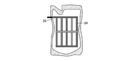
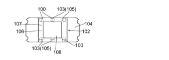
- FIGS. 17 to 20 exemplify other forms of the leg forming part 100 that forms at least three protruding leg parts 103 on the mounting part 102.
- FIG. The plan view of the bottom sheet 104 shown in FIGS. 17 to 20 is a portion of the bottom sheet 104 in the developed front view of the container sheet material 105 used for the sheet material container shown in FIG. It is an enlarged view.
- the leg forming part 100 that forms the projecting leg 103 on the mounting part 102 has a container in the non-adhesive region 106 as shown in FIG. 17B as a cross-sectional view.
- the convex portion 105 includes a non-encapsulated portion 108 in a state in which the convex portion is provided from the inside to the outside (the convex portion) 105 and the filler is enclosed in the non-adhesive region 106.
- the convex portion 105 can be easily provided on the bottom sheet 104 by, for example, heat embossing, sheet forming by pressure forming, vacuum forming, or the like.
- the protruding leg portion 103 formed by the convex processing portion 105 has four or more places (as shown in FIG. 17 (d) can be provided, and as shown in FIG. 17 (e), it can be provided only at three locations.
- the mounting portion 102 by the bottom filler enclosing portion 107 extending in an annular shape does not necessarily have to be annularly extended so as to surround one non-encapsulating portion 108, as shown in FIG. 17 (f). Two or more non-encapsulating portions 108 may be surrounded and extended in an annular shape.
- the leg forming part 100 that forms the projecting leg 103 on the mounting part 102 has a container in the non-adhesive region 106 as shown in FIG. 18B as a sectional view.
- the concave portion 109 is provided with a concave portion (concave portion) 109 from the outside to the inside, and the concave portion 109 bulges outward while the filler is enclosed in the non-adhesive region 106.
- the other portion of the bottom filler encapsulating portion 107 protrudes to the placement surface side and forms four protruding leg portions 103.
- the protruding legs 103 are arranged at four corners of a bottom filler encapsulating part 107 that extends in a rectangular ring shape surrounding the non-encapsulating part 108.
- the recessed portion 109 can be easily provided on the bottom sheet 104 by, for example, heat embossing, sheet forming by pressure forming, vacuum forming, or the like.
- the protruding leg 103 formed by the leg forming part 100 by the concave processing part 109 is formed by a bottom filler encapsulating part 107 surrounding the non-encapsulating part 108 and extending in a rectangular ring shape.
- the mounting portion 102 can be provided at four locations by being arranged at the central portion of each side portion, and can also be provided at three locations as shown in FIG.
- FIG. 18 (e) when the non-adhesive region 106 and the bottom filler encapsulating portion 107 are provided in a wider area than the non-encapsulating portion 108, a wide area bottom filler encapsulating portion 107 is provided. It is also possible to arrange the projecting legs 103 at three positions by arranging them in a well-balanced size.
- the leg forming part 100 that forms the projecting leg 103 on the mounting part 102 is provided in the bottom filler encapsulating part 107 as shown in FIG. 19B as a sectional view.
- the wrinkle guiding portion 110 is four linear groove processing portions 111 provided in the non-bonding region 106.
- linear groove processing portions 111 are provided at four central portions of each side portion of the mounting portion 102 by the bottom filler enclosing portion 107 that extends in a rectangular ring shape surrounding the non-encapsulating portion 108. Wrinkles 109 are provided so that they can be formed.
- the linear groove processing portion 111 can be easily provided on the bottom sheet 104 by, for example, heat embossing, sheet forming by pressure forming, vacuum forming, or the like.
- the wrinkle guiding portion 110 formed by the linear groove processing portion 111 is bent upward due to stress concentration on the linear groove processing portion 110 in a state where the filler is enclosed in the non-bonding region 106. (See FIG. 19 (b)), a portion between each pair of wrinkles 109 is formed as a projecting leg portion 103 so as to project downward from the wrinkle 109 portion.
- the wrinkle guiding portion 110 formed by the linear groove processing portion 111 has four corners of the bottom filler encapsulating portion 107 that extends around the non-encapsulating portion 108 and extends in a rectangular ring shape. It can also be formed at the four corners of the non-adhesive region 106 so that the wrinkles 109 are formed at the portions. As shown in FIG. 19 (d), the four corners and the central portion of the four sides are formed. It can also be formed in a total of eight locations.
- the mounting portion 102 by the bottom filler encapsulating portion 107 extending in an annular shape where the wrinkles 109 are formed does not necessarily extend around the rectangular non-encapsulating portion 108, and FIG. As shown in FIG. 6, the circular non-encapsulating portion 108 may be surrounded and extended.
- the leg forming portion 100 that forms the protruding leg 103 on the mounting portion 102 is shown in FIG. 19A as shown in FIG. 20B as a cross-sectional view.
- the bottom filler encapsulating portion 107 is provided with a wrinkle guiding portion 110 for guiding a plurality of wrinkles 109 to be formed, and the non-adhesive region 106 is filled with the filler. Further, a portion between each pair of adjacent wrinkles 109 protrudes downward from the wrinkle 109 portion to form a protruding leg portion 103.
- the wrinkle guiding portion 110 is formed by extending two ruled lines arranged in a straight line extending from the non-encapsulating portion 108 to the non-adhesive region 106.
- Two orthogonal ruled line processing portions 112 are provided with four wrinkles at the central portion of each side portion of the mounting portion 102 by the bottom filler enclosing portion 107 extending in a rectangular ring shape surrounding the non-encapsulating portion 108. 109 is formed.
- the ruled line processing unit 112 can be easily provided on the bottom sheet 104 by, for example, ruled line processing by pressing the edge of a knife or the like, or folding by adding a crease.
- the wrinkle guiding portion 110 formed by the ruled line processing portion 112 is bent upward due to stress concentration on the ruled line processing portion 112 in a state where the filler is sealed in the non-bonding region 106 to form a wrinkle 109 (FIG. 20). (See (b)), a portion between each pair of wrinkles 109 is formed as a protruding leg portion 103 so as to protrude below the wrinkle 109 portion.
- the wrinkle guiding portion 110 by the ruled line processing portion 112 is wrinkled at four corners of the bottom filler enclosing portion 107 extending in a rectangular ring shape surrounding the non-encapsulating portion.
- Two can be extended toward the corners of the non-adhesion region 106 so that 109 is formed, and as shown in FIG. 20 (d), it extends toward the corners and the central part of each side. It is also possible to provide four.
- the mounting portion 102 formed by the bottom filler encapsulating portion 107 extending in a ring shape in which the wrinkles 109 are formed does not necessarily extend around the rectangular non-encapsulating portion 108, and FIG. As shown in FIG. 5, the non-encapsulating portion 108 having other shapes may be surrounded and extended.
- the wrinkle guide part 110 by the ruled line processing part 112 and the wrinkle guide part 110 by the linear groove processing part 111 are not in contact with the bottom filler encapsulating part 107 by the non-adhesive region 106 as shown in FIG. It can also be provided continuously on both sides of the encapsulating part 108, and as shown in FIG. 21B, it can also be provided only on the bottom filler enclosing part 107 by the non-adhesive region 106, as shown in FIG. In addition, it can be provided only in the non-encapsulating portion 108. As shown in FIG.
- the one provided only in the non-encapsulating part 108 and the one provided continuously in both the bottom filler encapsulating part 107 and the non-encapsulating part 108 by the non-adhesive region 106 are mixed. You can also.
- the leg part formation part 100 is provided with the convex process part 105 shown to Fig.17 (a), the thing provided with the concave process part 109 shown to Fig.18 (a), and the linear form shown to Fig.19 (a).
- groove process part 111 and what has the wrinkle guide part 110 by the ruled line process part 112 shown to Fig.20 (a) can also be formed combining suitably. 22A and 22B, as an example in which the convex processing portion 105 is the protruding leg portion 103, the wrinkle guiding portion 110 formed by the convex processing portion 105, the concave processing portion 109, and the linear concave groove processing portion 111.
- FIG. 22C shows a leg forming unit 100 that combines the convex processing unit 105 and the wrinkle guiding unit 110 by the ruled line processing unit 112 as an example in which the convex processing unit 105 is the protruding leg 103. ing.
- the wrinkle induction part 110 by the convex process part 105, the concave process part 109, the linear groove processing part 111, and the wrinkle by the ruled line process part 112 which comprise the above leg part formation part 100 are comprised.
- the outer film layer and the inner film layer arranged on the non-adhesive region 106 of the bottom sheet 104 made of a sheet material having a plurality of film layers are mutually connected.
- a method of performing heat embossing, ruled line processing, folding processing, or the like on the outer film layer and the inner film layer after forming the non-bonded region 106 by welding can be used.
- a method of forming the non-adhesive region 106 by performing heat embossing, ruled line processing, folding processing, etc. on each of the outer film layer and the inner film layer and then welding these film layers is used. You can also. Further, a method of forming the non-adhesive region 106 by performing heat embossing, ruled line processing, folding processing, etc. on only the outer film layer and then welding the outer film layer and the inner film layer is used. You can also.
- seats 120a and 120a, and the inner side of the lower end part of these front part sheet
- the bottom edge portion of the lower joint portion 122 formed by joining the side edge portions on both sides of the bottom sheet 121 folded in half by heat sealing or the like to the bottom sheet 121 by the bottom filler encapsulating portion 123.
- the self-supporting stability when the sheet material container 125 is placed on the placement surface can be further improved so as not to protrude downward from the provided placement portion 124.
- FIG. 23 (a) As shown in the developed front view of the container sheet material 126 used in the sheet material container 125 in FIG. 23 (b), the front portion sheets 120a and 120a and the bottom sheet.
- a boundary notch 127 having a considerable width is formed at the boundary portion with 121 so as to extend inwardly along the boundary portion from the edge portions on both sides of these sheets.
- a lower end notch 128 is formed at the lower end portion of the lower joint portion 122 formed by joining the lower joint portion 122 and the lower joint portion 122, as shown in FIG. It becomes possible to arrange the lower end portion one step higher than the placement portion 124.
- the side edge portions on both sides of the lower end portion of the front portion sheet 120a, 120a and the side edge portions on both sides of the bottom sheet 121 are joined.
- the lower end notch is not provided in the lower end portion of the lower joint portion 122
- the lower end portion of the lower joint portion 122 easily hits the placement surface, and the sheet material container 125 ′ becomes unstable. Can be effectively avoided.
- the film layers constituting the sheet material do not necessarily have to be bonded by a lamination method using a laminate adhesive, and may be bonded by other known methods.
- a bonding method using other adhesives such as a UV curable adhesive or an instantaneous adhesive can also be employed.
- the interlayer provided with the non-adhesive region does not necessarily have to be adhered by a lamination method using a laminate adhesive, and may be adhered to have a non-adhesive region by other known methods.
- the non-adhesion region can also be provided by applying a non-adhesive treatment to the surface of the film layer, for example, by applying a paste-killing agent.
- the sheet material does not necessarily need to include three film layers including the innermost layer, the intermediate layer, and the outermost layer, and may include two or four or more film layers.
- the non-adhesive region is not necessarily formed between the innermost sealant film layer and the intermediate layer, and is not necessarily formed between the intermediate layer and the outermost layer. It may be formed.
- the intermediate layer can be configured to have a layer formed of, for example, a polyethylene resin used in the barrier film layer and the sealant film layer.
- a layer formed of, for example, a polyethylene resin used in the barrier film layer and the sealant film layer By heat-sealing the layer formed with the resin used in the sealant film layer and the sealant film layer, which is the innermost layer, using a patterned hot plate or heat seal bar, the non-adhesive region is intermediate It can also be formed in a desired shape between the layer and the innermost layer.
- the intermediate layer may be a single layer formed of a resin used in the sealant film layer.
- region can also be formed between an intermediate
- the layer formed with resin used with the said sealant film layer may be formed with resin different from resin which comprises the adjacent sealant film layer.
- the layer formed of the resin used in the sealant film layer is, for example, a low density polyethylene resin (LDPE), a medium density polyethylene resin (MDPE), a high density polyethylene resin (HDPE), a linear low density polyethylene resin ( L-LDPE), polypropylene resin (PP) and the like can be used.
- the adhesion includes not only adhesion but also heat sealing.
- the content stored in the storage unit may be a content liquid such as a liquid detergent, other content such as a granular material, or a food product or a medicine.
- the filler encapsulating portion formed by encapsulating the filler in the non-adhesive region is not limited to the shape of the above-described embodiment, and may have various patterns depending on the type and application of the container. Can be formed.
- the filler encapsulating part is not necessarily formed on both the body sheet and the bottom sheet of the housing part, and it is sufficient that the bottom filler enclosing part is provided only on the bottom sheet. Further, an external communication port may be provided in each of the trunk sheet and the bottom sheet.
- the filler enclosing portion does not necessarily have to be provided in a linear shape as a whole. For example, as shown in FIG.
- the linear filler enclosing portion 16 ′′ for example, a cylinder
- a circular (including a substantially circular) planar filler encapsulating portion 24 at the bottom corner of the body sheet 12a ′′ of the section 12 ′′.
- Concern of bag breakage due to falling By providing a planar filler enclosure 24 at the bottom corner of the body sheet 12a ′′, the drop strength of the sheet material container can be improved by the buffering effect of the filler enclosure 24.
- the filler encapsulating portion formed by encapsulating the filler in the non-adhesive region may be formed at the same time as the contents are accommodated, or may be accommodated after being formed in advance. You may form after accommodating.
- the sheet material container 30 can be used as a bottle-shaped container to which a trigger type discharge device 31 is attached.
- the sheet material container 30 is used as a bottle-shaped container, it is possible to effectively reinforce the bottle shape so that the bottle shape is firmly held by the reinforcing filler enclosure portion 32.
- the external communication port 35 communicating with the reinforcing filler enclosure 34 can be provided so as to open in the lateral direction.
- the sheet material container of the present invention may be a gusset type sheet material container having a flange on a side surface. That is, the trunk
- the present invention further discloses the following sheet material container, sheet material container manufacturing method, container product, container product manufacturing method, container sheet material, and container sheet material manufacturing method with respect to the above-described embodiments.
- a sheet material container that includes a body portion and a bottom portion that is disposed to face the placement surface, and is configured of a sheet material in which a plurality of film layers are laminated,
- the body sheet constituting the body part includes a joint part in which sheet materials are joined to the peripheral part,
- the bottom sheet constituting the bottom portion is provided with a non-adhesive region between the plurality of film layers, and a filler is enclosed in the non-adhesive region to form a bottom filler encapsulating portion.
- Sheet material container that includes a body portion and a bottom portion that is disposed to face the placement surface, and is configured of a sheet material in which a plurality of film layers are laminated,
- the body sheet constituting the body part includes a joint part in which sheet materials are joined to the peripheral part
- ⁇ 4> The sheet material container according to any one of ⁇ 1> to ⁇ 3>, wherein the bottom filler encapsulating portion preferably includes a portion that continues from the front side to the back side facing each other in the trunk portion.
- the bottom sheet includes a non-encapsulating portion that is surrounded by a non-adhesive region that forms the bottom filler encapsulating portion and does not enclose the filler. 4>.
- the bottom filler encapsulating portion is formed continuously along the periphery of the placement portion (bottom portion) in the bottom sheet, according to any one of the above ⁇ 2> to ⁇ 5> Sheet material container.
- the body sheet includes a pair of front sheets facing forward and backward, and the front sheet is filled with a filler in a non-adhesive region provided between the plurality of film layers.
- a front portion filler encapsulating portion is formed, and a non-adhesive region constituting the front portion filler encapsulating portion communicates with a non-adhesive region forming the bottom filler encapsulating portion in the bottom sheet.
- the sheet material container according to any one of the above items ⁇ 1> to ⁇ 6>.
- the interlayer of the plurality of film layers provided with the non-adhesive region is bonded using an adhesive, and the adhesive is applied by an application pattern including the non-adhesive region.
- the interlayer of the plurality of film layers provided with the non-adhesive region is bonded using an adhesive, and is on the surface of at least one film layer of a portion corresponding to the previous non-adhesive region
- a peripheral portion of the bottom sheet is provided with a joint portion where sheet materials are joined to each other, and the bottom portion sheet or the joint portion of the peripheral portion of the bottom sheet opens to the non-adhesive region.
- the sheet material container according to any one of ⁇ 1> to ⁇ 10>, wherein an external communication port that communicates is provided, and the external communication port is sealed after supplying a filler to the non-adhesive region .
- ⁇ 12> The method for producing a sheet material container according to any one of ⁇ 1> to ⁇ 10>, wherein the non-adhesive region forms a raw sheet of the sheet material provided on the bottom sheet portion.
- seat material container including the process of forming the said bottom part filling material enclosure part.
- a sheet material for a container that is used for a sheet material container according to any one of the above items ⁇ 1> to ⁇ 11> and is formed using a sheet material in which a plurality of film layers are laminated, A body sheet, a joint between sheet materials formed on the peripheral edge of the body sheet, and a bottom sheet, The bottom sheet is provided with a fold for folding, It is in a state where it is folded flatly over the folding fold, The bottom sheet is a container sheet material in which a non-adhesive region in which a filler is enclosed is provided between the plurality of film layers.
- a method for manufacturing a container product according to ⁇ 13> including a step of storing contents in a storage portion surrounded by the body portion and the bottom portion of the sheet material container.
- a method for producing a container sheet material comprising: joining a peripheral portion of a portion corresponding to a container sheet material; and cutting the joined raw material into a predetermined dimension.
- the sheet material container according to any one of ⁇ 1> to ⁇ 11>, wherein the filler is any one of a fluid, a granular material, a resin, a foamed material, or a mixture appropriately selected from these. .
- the film layer provided with the non-adhesive region has a layer formed of a resin used in the sealant film layer, and the film layer and the sealant film layer adjacent to the film layer are heated.
- the trunk sheet includes a pair of front and rear front sheets, and these front sheets are filled in a non-adhesive region provided between layers of the plurality of film layers constituting the sheet material. Is formed, and a front portion filler encapsulating portion is formed, and the front portion filler encapsulating portion includes a lateral enclosing portion, a longitudinal enclosing portion, and a bottom curve enclosing portion.
- the sheet material container according to any one of 1> to ⁇ 11>.
- an external communication opening for supplying a filler to the non-adhesive region is formed in the joint portion of the upper side portion of one front portion sheet of the pair of front and rear front sheet portions.
- ⁇ 7> to ⁇ 11>, ⁇ 19>, and ⁇ 20> are provided in communication with the non-adhering region, and the external communication port is sealed after the filler is supplied to the non-adhering region.
- the sheet material container according to any one of the above.
- one inner wall surface facing is a wall surface by a sealant film layer
- the other inner wall surface is a wall surface by a barrier film layer
- the other inner wall surface is formed by the barrier film layer.
- a planar, circular, or spherical filler encapsulating part wider than the width of the linear filler enclosing part is interposed in the linear filler enclosing part alone or in an appropriate combination.
- the bottom filler encapsulating part includes an intersecting enclosing part provided substantially perpendicularly to a folding fold provided in the bottom sheet part.
- Sheet material container Preferably, the bottom filler encapsulating part includes an intersecting enclosing part provided substantially perpendicularly to a folding fold provided in the bottom sheet part. Sheet material container.
- the bottom filler encapsulating portion is continuously arranged so as to straddle a pair of joint portions on both sides joining the bottom portion of the front and rear pair of front portion sheets and the peripheral portion of the bottom gusset portion sheet.
- the non-encapsulating portion has a corner portion of the non-encapsulating portion directed to an intermediate portion of the four sides of the rectangular encapsulating portion spaced apart from the four rectangular corner portions.
- a sheet material container including a body portion and a bottom portion disposed to face a placement surface, which is composed of a sheet material obtained by laminating a plurality of film layers,
- the body sheet constituting the body part includes a joint part in which sheet materials are joined to the peripheral part,
- a non-adhesive region is provided between the plurality of film layers at the boundary between the bottom sheet constituting the bottom and the trunk sheet, and a filler is enclosed in the non-adhesive region.
- a sheet material container in which a bottom filler encapsulating part is formed.
- a sheet material container including a body portion and a bottom portion disposed to face a placement surface, which is formed of a sheet material obtained by laminating a plurality of film layers
- the body sheet constituting the body part includes a joint part in which sheet materials are joined to the peripheral part
- the trunk sheet includes a pair of front surfaces and a pair of side surfaces between the front surface and the front surface, The joint is located in a range of the pair of side surfaces;
- a non-adhesion region is provided between the plurality of film layers at the boundary between the front surface and the side surface, and a filler is enclosed in the adhesion region, whereby a front portion filler encapsulating portion is formed.
- a sheet material container comprising a body portion and a bottom portion disposed to face the mounting surface, the sheet material having a plurality of film layers.
- the trunk sheet that constitutes the trunk section includes a joint portion in which sheet materials are joined to each other at the peripheral portion,
- the bottom sheet constituting the bottom portion is provided with a non-adhesive region between the plurality of film layers, and the non-adhesive region is filled with a filler to form a bottom filler encapsulating portion.
- the bottom filler enclosing portion extends in an annular shape so as to surround the non-encapsulating portion of the bottom sheet, and forms at least three projecting leg portions that are placed on the placing surface and make the container self-supporting.
- the protruding leg portion is a sheet material container that protrudes to the placement surface side from the other portion of the bottom filler enclosing portion by a leg forming portion provided on the bottom portion.
- the leg forming portion includes a portion whose width in a direction perpendicular to the extending direction is larger than the other portion in the non-bonding region, and the filler is provided in the non-bonding region.
- the portion having the larger width is placed more than the other portion of the bottom filler encapsulating portion by expanding so that the cross-sectional area is larger than the other portion.
- the leg forming portion includes a portion of the non-adhering region that is convexly processed from the inside to the outside of the container, and a filler is enclosed in the non-adhering region.
- the portion that has been subjected to the convex processing protrudes more toward the mounting surface than the other portion of the bottom filler encapsulating portion, and forms the protruding leg portion.
- the leg forming portion includes a portion in which concave processing is performed from the outside to the inside of the container in the non-adhesion region, and a filler is enclosed in the non-adhesion region In the recessed portion, the outward bulge is suppressed, and the other portion of the bottom filler encapsulating portion protrudes to the mounting surface side to form the protruding leg portion.
- the leg forming portion includes a wrinkle guiding portion that guides the bottom filler filling portion so that a plurality of wrinkles are formed, and the filler is sealed in the non-bonding region.
- a portion between each pair of adjacent wrinkles formed in the state protrudes below the wrinkle portion and forms the protruding leg portion.
- the wrinkle guiding portion is preferably a linear groove processing portion and / or a ruled line processing portion provided in the non-bonding region.
- ⁇ 40> The method for manufacturing a sheet material container according to any one of ⁇ 34> to ⁇ 39>, wherein the non-adhesion region is formed on the bottom sheet portion of the sheet material. , A step of joining the peripheral portions of the sheet materials corresponding to the individual sheet material containers of the original fabric, a step of cutting the joined original fabric into a predetermined size, and a filler in the non-adhesive region And the manufacturing method of the sheet
- ⁇ 41> A container product using the sheet material container according to any one of ⁇ 34> to ⁇ 39>, wherein the contents are stored in a storage portion surrounded by the body portion and the bottom portion.
- ⁇ 42> The method for manufacturing a container product according to ⁇ 41>, including a step of storing contents in a storage portion surrounded by the body portion and the bottom portion of the sheet material container.
- a sheet material for a container which is used for a sheet material container according to any one of ⁇ 34> to ⁇ 39>, and is formed using a sheet material obtained by laminating a plurality of film layers, A body sheet, a joint between sheet materials formed on the peripheral edge of the body sheet, and a bottom sheet, The bottom sheet is provided with a fold for folding, It is in a state where it is folded flatly over the folding fold,
- the bottom sheet is a container sheet material in which a non-adhesive region in which a filler is enclosed is provided between the plurality of film layers.
- ⁇ 44> The method for producing a container sheet material according to ⁇ 43>, wherein the non-adhesive region forms an original sheet of the sheet material provided on the bottom sheet, and individual containers of the original sheet
- the manufacturing method of the sheet material for containers including the process of joining the peripheral part of the part corresponding to the sheet material for sheets, and the process of cut
- Sheet material container of the present invention method for producing the sheet material container, container product using the sheet material container, method for producing the container product, sheet material for containers used in the sheet material container, or sheet for the container
- the material manufacturing method it is possible to improve the degree of freedom of selection of the shape and arrangement position of the reinforcing filler enclosure, and to provide the filler enclosure at an arbitrary position of the container.
- the bottom sheet portion can be effectively reinforced by the filler enclosing portion to improve the self-supporting stability of the container or to increase the rigidity of the bottom sheet portion.
- the method for manufacturing the sheet material container, and the container sheet material used for the sheet material container the container can be used regardless of the amount of the contained material by the filler enclosure portion. It is possible to improve the three-dimensional shape retaining property, to increase the drop strength, or to improve the three-dimensional formability from the container sheet material. Moreover, according to the sheet
Abstract
L'invention concerne un contenant de matériau de feuille (90) qui est formé à partir de matériaux de feuille (20) ayant une pluralité de couches de film (20a, 20b, 20c) et comprend une partie de corps (12) et une partie inférieure (25) qui fait face à une surface de montage, une feuille de partie de corps (93a) qui constitue la partie de corps (12) comprenant, dans une partie périphérique, une partie de jonction (94) au niveau de laquelle les matériaux de feuille (20) sont reliés. Une feuille de surface inférieure (93b) qui constitue la partie inférieure (25) comprend une région non-adhésive (99) entre les couches de film (20a, 20b, 20c). La région non-adhésive (99) forme une partie (96b) pour insérer un matériau de remplissage de partie inférieure. La partie (96b) pour insérer un matériau de remplissage de partie inférieure entoure une partie de non-insertion (96j) et s'étend dans une forme annulaire, et comprend au moins trois parties de patte en saillie (96m) qui sont montées sur la surface de montage et permettent au contenant (90) de se soutenir lui-même. Les parties de patte en saillie (96m) font saillie davantage vers le côté surface de montage que d'autres parties de la partie (96b) pour insérer un matériau de remplissage de partie inférieure en raison d'une partie de formation de partie de patte (100).
Priority Applications (6)
| Application Number | Priority Date | Filing Date | Title |
|---|---|---|---|
| JP2016574019A JP6153185B1 (ja) | 2015-09-09 | 2016-09-08 | シート材容器 |
| EP16844459.4A EP3348488A4 (fr) | 2015-09-09 | 2016-09-08 | Contenant de matériau de feuille |
| US15/758,654 US11059626B2 (en) | 2015-09-09 | 2016-09-08 | Sheet material container |
| CN201680052125.6A CN108025836B (zh) | 2015-09-09 | 2016-09-08 | 片材容器 |
| CN202110325209.5A CN112960264B (zh) | 2015-09-09 | 2016-09-08 | 片材容器 |
| US17/366,852 US11878841B2 (en) | 2015-09-09 | 2021-07-02 | Sheet material container |
Applications Claiming Priority (2)
| Application Number | Priority Date | Filing Date | Title |
|---|---|---|---|
| PCT/JP2015/075582 WO2017042905A1 (fr) | 2015-09-09 | 2015-09-09 | Contenant en matériau en feuilles |
| JPPCT/JP2015/075582 | 2015-09-09 |
Related Child Applications (2)
| Application Number | Title | Priority Date | Filing Date |
|---|---|---|---|
| US15/758,654 A-371-Of-International US11059626B2 (en) | 2015-09-09 | 2016-09-08 | Sheet material container |
| US17/366,852 Continuation US11878841B2 (en) | 2015-09-09 | 2021-07-02 | Sheet material container |
Publications (1)
| Publication Number | Publication Date |
|---|---|
| WO2017043598A1 true WO2017043598A1 (fr) | 2017-03-16 |
Family
ID=58239251
Family Applications (2)
| Application Number | Title | Priority Date | Filing Date |
|---|---|---|---|
| PCT/JP2015/075582 WO2017042905A1 (fr) | 2015-09-09 | 2015-09-09 | Contenant en matériau en feuilles |
| PCT/JP2016/076507 WO2017043598A1 (fr) | 2015-09-09 | 2016-09-08 | Contenant de matériau de feuille |
Family Applications Before (1)
| Application Number | Title | Priority Date | Filing Date |
|---|---|---|---|
| PCT/JP2015/075582 WO2017042905A1 (fr) | 2015-09-09 | 2015-09-09 | Contenant en matériau en feuilles |
Country Status (6)
| Country | Link |
|---|---|
| US (2) | US11059626B2 (fr) |
| EP (1) | EP3348488A4 (fr) |
| JP (3) | JP6153185B1 (fr) |
| CN (2) | CN112960264B (fr) |
| TW (1) | TWI623467B (fr) |
| WO (2) | WO2017042905A1 (fr) |
Cited By (5)
| Publication number | Priority date | Publication date | Assignee | Title |
|---|---|---|---|---|
| JP2017141063A (ja) * | 2015-09-09 | 2017-08-17 | 花王株式会社 | シート材容器 |
| JP2020033025A (ja) * | 2018-08-27 | 2020-03-05 | 大和製罐株式会社 | 容器用シート材からなる容器 |
| WO2022202787A1 (fr) * | 2021-03-26 | 2022-09-29 | 大和製罐株式会社 | Récipient en forme de sac rempli de fluide |
| US20220324624A1 (en) * | 2019-09-09 | 2022-10-13 | Fuji Seal International, Inc. | Sheet material container |
| US11738928B2 (en) | 2019-04-04 | 2023-08-29 | Kao Corporation | Sheet for container |
Families Citing this family (13)
| Publication number | Priority date | Publication date | Assignee | Title |
|---|---|---|---|---|
| US11261008B2 (en) | 2017-03-07 | 2022-03-01 | Kao Corporation | Sheet material container |
| CN109641687A (zh) | 2017-03-07 | 2019-04-16 | 花王株式会社 | 容器 |
| CN109641680B (zh) | 2017-03-07 | 2022-04-26 | 花王株式会社 | 薄片材料容器 |
| JP2019147256A (ja) * | 2018-02-26 | 2019-09-05 | 東洋製罐株式会社 | フィルムの立体成形方法、フィルム成形体の製造方法、およびフィルム成形体 |
| WO2020012607A1 (fr) | 2018-07-12 | 2020-01-16 | 花王株式会社 | Contenant de matériau en feuille |
| JP6510151B1 (ja) | 2018-07-12 | 2019-05-08 | 花王株式会社 | シート材容器 |
| EP3889066A4 (fr) * | 2018-11-26 | 2022-08-24 | Kao Corporation | Contenant en matériau en feuille |
| JP2020083426A (ja) * | 2018-11-29 | 2020-06-04 | 花王株式会社 | シート材容器 |
| AR118754A1 (es) * | 2019-05-15 | 2021-10-27 | Dow Global Technologies Llc | Bolsa flexible con canal de flujo |
| WO2021181691A1 (fr) | 2020-03-13 | 2021-09-16 | 花王株式会社 | Contenant en matériau en feuille |
| JP7288139B2 (ja) | 2020-03-13 | 2023-06-06 | 花王株式会社 | シート材容器 |
| DE102020113030B4 (de) * | 2020-05-13 | 2022-05-12 | Syster Tjarks | Behältnis zur Aufnahme eines flexiblen Inhalts sowie Folienverpackung |
| US11618177B1 (en) | 2022-04-12 | 2023-04-04 | Bradley W Boesel | Orbital knife |
Citations (3)
| Publication number | Priority date | Publication date | Assignee | Title |
|---|---|---|---|---|
| JP2015000726A (ja) * | 2013-06-13 | 2015-01-05 | 凸版印刷株式会社 | 自立性包装袋 |
| WO2015051539A1 (fr) * | 2013-10-11 | 2015-04-16 | The Procter & Gamble Company | Récipient souple à maintien vertical |
| JP2015520707A (ja) * | 2012-05-07 | 2015-07-23 | ザ プロクター アンド ギャンブルカンパニー | 可撓性容器 |
Family Cites Families (58)
| Publication number | Priority date | Publication date | Assignee | Title |
|---|---|---|---|---|
| US4573202A (en) * | 1984-01-20 | 1986-02-25 | Aaron Lee | Container with inflatable, floating liner of uniform thickness |
| US5254073A (en) * | 1990-04-27 | 1993-10-19 | Kapak Corporation | Method of making a vented pouch |
| US5059036A (en) * | 1990-04-27 | 1991-10-22 | Kapak Corporation | Vented pouch arrangement and method |
| JP3287939B2 (ja) | 1994-02-18 | 2002-06-04 | 株式会社ジェイ・ピー・エム | プラスチック容器 |
| JP3284004B2 (ja) * | 1994-06-23 | 2002-05-20 | エアーボックス協同組合 | 緩衝性包装材 |
| DK82794A (da) | 1994-07-08 | 1996-01-09 | Danapak Holding As | Emballagebeholder |
| JP3709155B2 (ja) | 1994-11-18 | 2005-10-19 | 株式会社細川洋行 | バッグインボックス用袋体およびバッグインボックス |
| TW367297B (en) | 1994-11-18 | 1999-08-21 | Hosokawa Yoko Kk | Bag for bag-in-box and bag-in-box |
| SE9602739D0 (sv) | 1996-07-10 | 1996-07-10 | Ingemar Naeslund | Förpackning |
| JP3006528B2 (ja) | 1997-01-23 | 2000-02-07 | フジモリプラケミカル株式会社 | 自動通気包装袋 |
| JP2000109095A (ja) | 1998-10-09 | 2000-04-18 | Mitsubishi Materials Corp | 袋状包装容器 |
| SE0101440L (sv) * | 2001-04-25 | 2002-10-08 | Eco Lean Res & Dev As | Förpackning och sätt att framställa sådan förpackning |
| US7722254B2 (en) * | 2002-10-30 | 2010-05-25 | Pouch Pac Innovations, Llc | Flexible pouch and method of forming a flexible pouch |
| SE525952C2 (sv) * | 2003-10-02 | 2005-05-31 | Eco Lean Res & Dev As | Metod och anordning för gasfyllning och försegling av en för gasfyllning avsedd kanal i en förpackning av kollapsande slag, samt ett förpackningsämne innefattande en sådan kanal |
| ES2245207B1 (es) * | 2003-12-30 | 2007-02-16 | Volpak, S.A. | Envase de material flexible. |
| JP4736364B2 (ja) | 2004-07-20 | 2011-07-27 | 凸版印刷株式会社 | 自立袋 |
| CN2728206Y (zh) * | 2004-09-29 | 2005-09-28 | 张斌 | 花草植物生长自立袋 |
| KR200397141Y1 (ko) | 2005-07-13 | 2005-09-28 | (주)에어텍네츄럴 | 공기 주입식 완충 포장재 구조 |
| JP5049537B2 (ja) * | 2005-12-14 | 2012-10-17 | 押尾産業株式会社 | 自立袋 |
| DK1862189T3 (da) | 2006-06-02 | 2011-11-21 | Fresenius Medical Care De Gmbh | Beholder fyldt med et flydende koncentrat til fremstilling af dialysat |
| SE0700769L (sv) * | 2007-03-28 | 2008-09-29 | Ecolean Res & Dev As | Rivanvisning |
| CA2597807A1 (fr) * | 2007-08-14 | 2009-02-14 | Iain N.B. Mackay | Recipient de confinement pliable |
| SE0702170L (sv) * | 2007-09-28 | 2009-03-10 | Ecolean Res & Dev As | Metod för gasfyllning av ett handtagsparti hos en förpackning samt metod för att framställa en förpackning |
| US8209995B2 (en) | 2009-04-23 | 2012-07-03 | Packit, Llc | Collapsible insulated container |
| JP5540232B2 (ja) * | 2009-05-08 | 2014-07-02 | 株式会社悠心 | 液状物充填包装構造体 |
| CN201745870U (zh) | 2009-12-10 | 2011-02-16 | 刘醇汶 | 包装袋新结构 |
| WO2012073004A2 (fr) * | 2010-11-29 | 2012-06-07 | Ian Darby | Récipient, découpe de récipient et procédé de fabrication associé |
| JP2013010525A (ja) * | 2011-06-29 | 2013-01-17 | Kao Corp | 商品包装体 |
| US9802719B2 (en) * | 2012-08-06 | 2017-10-31 | The Procter & Gamble Company | Methods of making flexible containers |
| JP6217155B2 (ja) * | 2013-06-13 | 2017-10-25 | 凸版印刷株式会社 | 包装袋 |
| BR112016002170A2 (pt) * | 2013-08-01 | 2017-08-01 | Procter & Gamble | melhorias na interação tátil com embalagem de filme com volumes de suporte estrutural contendo ar |
| MX2016004422A (es) * | 2013-10-11 | 2016-07-05 | Procter & Gamble | Envase flexible desechable. |
| CN105764808A (zh) * | 2013-11-06 | 2016-07-13 | 宝洁公司 | 容易排空的柔性容器 |
| JP2016538204A (ja) * | 2013-11-06 | 2016-12-08 | ザ プロクター アンド ギャンブル カンパニー | 通気孔システムを有する可撓性容器 |
| RU2016112351A (ru) * | 2013-11-06 | 2017-12-11 | Дзе Проктер Энд Гэмбл Компани | Эластичные контейнеры и способы их изготовления |
| WO2015069819A1 (fr) * | 2013-11-06 | 2015-05-14 | The Procter & Gamble Company | Récipients souples et leurs procédés de formage |
| RU2016112352A (ru) * | 2013-11-06 | 2017-12-07 | Дзе Проктер Энд Гэмбл Компани | Эластичные контейнеры и способы их изготовления |
| ES2675922T3 (es) * | 2013-11-06 | 2018-07-13 | The Procter & Gamble Company | Recipientes flexibles con válvulas flexibles |
| USD747195S1 (en) * | 2014-02-14 | 2016-01-12 | Clear Lam Packaging, Inc. | Film for packaging production |
| USD747202S1 (en) * | 2014-02-28 | 2016-01-12 | Clear Lam Packaging, Inc. | Film used to make packages |
| USD753995S1 (en) * | 2014-03-07 | 2016-04-19 | Clear Lam Packaging, Inc. | Film for packaging production |
| BR112017012866A2 (pt) * | 2014-12-19 | 2018-01-30 | Procter & Gamble | recipientes flexíveis com fácil dimensionamento variável |
| EP3233662A1 (fr) * | 2014-12-19 | 2017-10-25 | The Procter and Gamble Company | Procédé de fabrication d'une gamme de récipients flexibles |
| US20160176584A1 (en) * | 2014-12-19 | 2016-06-23 | The Procter & Gamble Company | Flexible Containers with Easily Variable Sizing |
| EP3233664B1 (fr) * | 2014-12-19 | 2019-08-28 | The Procter and Gamble Company | Procédé de fabrication d'une gamme de récipients souples |
| BR112017012878A2 (pt) * | 2014-12-19 | 2018-01-30 | Procter & Gamble | uma linha de recipientes flexíveis |
| BR112017021707A2 (pt) * | 2015-04-10 | 2018-07-10 | Procter & Gamble | recipientes flexíveis com vedações de reforço |
| WO2016164692A1 (fr) * | 2015-04-10 | 2016-10-13 | The Procter & Gamble Company | Contenants souples à bec verseur intégré |
| US9914575B2 (en) * | 2015-04-10 | 2018-03-13 | The Procter & Gamble Company | Flexible containers with puckered corners |
| KR101971817B1 (ko) * | 2015-04-10 | 2019-04-23 | 더 프록터 앤드 갬블 캄파니 | 제품 분배 가시화부를 가진 가요성 용기 |
| US20160297591A1 (en) * | 2015-04-10 | 2016-10-13 | The Procter & Gamble Company | Flexible Containers with Intermediate Bottom Members |
| JP6669775B2 (ja) * | 2015-05-06 | 2020-03-18 | ザ プロクター アンド ギャンブル カンパニーThe Procter & Gamble Company | ガセットを有する可撓性容器の形成方法 |
| JP6527251B2 (ja) * | 2015-06-30 | 2019-06-05 | ザ プロクター アンド ギャンブル カンパニーThe Procter & Gamble Company | 取り外し可能な部分を有する可撓性容器 |
| WO2017042905A1 (fr) * | 2015-09-09 | 2017-03-16 | 花王株式会社 | Contenant en matériau en feuilles |
| US10457457B2 (en) * | 2016-04-26 | 2019-10-29 | The Procter & Gamble Company | Flexible containers with bottom support structure |
| CN109641680B (zh) | 2017-03-07 | 2022-04-26 | 花王株式会社 | 薄片材料容器 |
| US11261008B2 (en) | 2017-03-07 | 2022-03-01 | Kao Corporation | Sheet material container |
| CN109641687A (zh) | 2017-03-07 | 2019-04-16 | 花王株式会社 | 容器 |
-
2015
- 2015-09-09 WO PCT/JP2015/075582 patent/WO2017042905A1/fr active Application Filing
-
2016
- 2016-09-08 WO PCT/JP2016/076507 patent/WO2017043598A1/fr active Application Filing
- 2016-09-08 CN CN202110325209.5A patent/CN112960264B/zh active Active
- 2016-09-08 EP EP16844459.4A patent/EP3348488A4/fr active Pending
- 2016-09-08 US US15/758,654 patent/US11059626B2/en active Active
- 2016-09-08 JP JP2016574019A patent/JP6153185B1/ja active Active
- 2016-09-08 CN CN201680052125.6A patent/CN108025836B/zh active Active
- 2016-09-09 TW TW105129378A patent/TWI623467B/zh active
-
2017
- 2017-05-23 JP JP2017102163A patent/JP6588497B2/ja active Active
-
2019
- 2019-09-12 JP JP2019165998A patent/JP6876763B2/ja active Active
-
2021
- 2021-07-02 US US17/366,852 patent/US11878841B2/en active Active
Patent Citations (3)
| Publication number | Priority date | Publication date | Assignee | Title |
|---|---|---|---|---|
| JP2015520707A (ja) * | 2012-05-07 | 2015-07-23 | ザ プロクター アンド ギャンブルカンパニー | 可撓性容器 |
| JP2015000726A (ja) * | 2013-06-13 | 2015-01-05 | 凸版印刷株式会社 | 自立性包装袋 |
| WO2015051539A1 (fr) * | 2013-10-11 | 2015-04-16 | The Procter & Gamble Company | Récipient souple à maintien vertical |
Non-Patent Citations (1)
| Title |
|---|
| See also references of EP3348488A4 * |
Cited By (8)
| Publication number | Priority date | Publication date | Assignee | Title |
|---|---|---|---|---|
| JP2017141063A (ja) * | 2015-09-09 | 2017-08-17 | 花王株式会社 | シート材容器 |
| JP2020033025A (ja) * | 2018-08-27 | 2020-03-05 | 大和製罐株式会社 | 容器用シート材からなる容器 |
| WO2020045270A1 (fr) * | 2018-08-27 | 2020-03-05 | 大和製罐株式会社 | Récipient formé à partir d'un matériau en feuille de récipient |
| JP7094835B2 (ja) | 2018-08-27 | 2022-07-04 | 大和製罐株式会社 | 容器用シート材からなる容器 |
| US11738928B2 (en) | 2019-04-04 | 2023-08-29 | Kao Corporation | Sheet for container |
| US20220324624A1 (en) * | 2019-09-09 | 2022-10-13 | Fuji Seal International, Inc. | Sheet material container |
| US11713172B2 (en) * | 2019-09-09 | 2023-08-01 | Fuji Seal International, Inc. | Sheet material container |
| WO2022202787A1 (fr) * | 2021-03-26 | 2022-09-29 | 大和製罐株式会社 | Récipient en forme de sac rempli de fluide |
Also Published As
| Publication number | Publication date |
|---|---|
| JP6876763B2 (ja) | 2021-05-26 |
| CN108025836A (zh) | 2018-05-11 |
| WO2017042905A1 (fr) | 2017-03-16 |
| EP3348488A4 (fr) | 2019-03-27 |
| CN108025836B (zh) | 2021-04-16 |
| JPWO2017043598A1 (ja) | 2017-09-07 |
| US20210339915A1 (en) | 2021-11-04 |
| JP2017141063A (ja) | 2017-08-17 |
| CN112960264A (zh) | 2021-06-15 |
| JP6588497B2 (ja) | 2019-10-09 |
| JP2019206398A (ja) | 2019-12-05 |
| TWI623467B (zh) | 2018-05-11 |
| US11878841B2 (en) | 2024-01-23 |
| CN112960264B (zh) | 2023-02-03 |
| TW201718356A (zh) | 2017-06-01 |
| US11059626B2 (en) | 2021-07-13 |
| JP6153185B1 (ja) | 2017-06-28 |
| EP3348488A1 (fr) | 2018-07-18 |
| US20190248546A1 (en) | 2019-08-15 |
Similar Documents
| Publication | Publication Date | Title |
|---|---|---|
| JP6588497B2 (ja) | シート材容器 | |
| JP6193535B1 (ja) | 容器 | |
| ES2619558T3 (es) | Envoltorio inflable y método para la fabricación del mismo | |
| ES2432678T3 (es) | Embalaje de envío inflable y procedimiento para hacer el mismo | |
| JP6803306B2 (ja) | 容器 | |
| CN109641681B (zh) | 薄片材料容器 | |
| JP6879784B2 (ja) | シート材容器 | |
| JP2018144856A (ja) | 軟包材容器用中間材、軟包材容器の製造方法及び軟包材容器包装体の製造方法 | |
| JP6904691B2 (ja) | シート材からなる容器およびその容器の製造方法 | |
| CN106081357B (zh) | 方形流体包装装置 | |
| US20240132253A1 (en) | Sheet material container | |
| JP5146893B1 (ja) | ブロック型空気封入緩衝材及びその製造方法 | |
| TW201710158A (zh) | 片材容器 | |
| JP7288140B2 (ja) | 容器 | |
| CN215206372U (zh) | 充气包装装置 | |
| JP7365222B2 (ja) | 容器 | |
| JP7350154B2 (ja) | 容器 | |
| JP2017007694A (ja) | 容器用シート材および該容器用シート材によって構成される容器 | |
| JP6186526B1 (ja) | 一体型逆止弁機能を有するエアー緩衝材 | |
| CN115515860A (zh) | 片材容器的制造方法 | |
| JP2021176765A (ja) | シート材容器の製造方法 | |
| BRPI1013746B1 (pt) | Embalagem postal inflável |
Legal Events
| Date | Code | Title | Description |
|---|---|---|---|
| ENP | Entry into the national phase |
Ref document number: 2016574019 Country of ref document: JP Kind code of ref document: A |
|
| 121 | Ep: the epo has been informed by wipo that ep was designated in this application |
Ref document number: 16844459 Country of ref document: EP Kind code of ref document: A1 |
|
| NENP | Non-entry into the national phase |
Ref country code: DE |
|
| WWE | Wipo information: entry into national phase |
Ref document number: 2016844459 Country of ref document: EP |