WO2017010264A1 - 車両制御装置、車両制御方法、および車両制御プログラム - Google Patents
車両制御装置、車両制御方法、および車両制御プログラム Download PDFInfo
- Publication number
- WO2017010264A1 WO2017010264A1 PCT/JP2016/068805 JP2016068805W WO2017010264A1 WO 2017010264 A1 WO2017010264 A1 WO 2017010264A1 JP 2016068805 W JP2016068805 W JP 2016068805W WO 2017010264 A1 WO2017010264 A1 WO 2017010264A1
- Authority
- WO
- WIPO (PCT)
- Prior art keywords
- event
- control
- vehicle
- unit
- executed
- Prior art date
Links
- 238000000034 method Methods 0.000 title claims description 61
- 230000002159 abnormal effect Effects 0.000 claims abstract description 108
- 230000009471 action Effects 0.000 claims abstract description 96
- 238000001514 detection method Methods 0.000 claims abstract description 69
- 230000005856 abnormality Effects 0.000 claims abstract description 64
- 230000001133 acceleration Effects 0.000 claims abstract description 14
- 230000008859 change Effects 0.000 claims description 116
- 230000007704 transition Effects 0.000 claims description 83
- 230000008569 process Effects 0.000 claims description 39
- 238000012545 processing Methods 0.000 claims description 10
- 238000004891 communication Methods 0.000 description 19
- 238000010586 diagram Methods 0.000 description 8
- 230000006870 function Effects 0.000 description 7
- 230000006399 behavior Effects 0.000 description 5
- 238000002485 combustion reaction Methods 0.000 description 3
- 239000000446 fuel Substances 0.000 description 3
- 238000003384 imaging method Methods 0.000 description 2
- 230000004044 response Effects 0.000 description 2
- LFQSCWFLJHTTHZ-UHFFFAOYSA-N Ethanol Chemical compound CCO LFQSCWFLJHTTHZ-UHFFFAOYSA-N 0.000 description 1
- UFHFLCQGNIYNRP-UHFFFAOYSA-N Hydrogen Chemical compound [H][H] UFHFLCQGNIYNRP-UHFFFAOYSA-N 0.000 description 1
- 206010039203 Road traffic accident Diseases 0.000 description 1
- 230000002547 anomalous effect Effects 0.000 description 1
- 238000010276 construction Methods 0.000 description 1
- 238000012937 correction Methods 0.000 description 1
- 238000005516 engineering process Methods 0.000 description 1
- 239000012530 fluid Substances 0.000 description 1
- 230000004927 fusion Effects 0.000 description 1
- 235000021189 garnishes Nutrition 0.000 description 1
- 230000005484 gravity Effects 0.000 description 1
- 229910052739 hydrogen Inorganic materials 0.000 description 1
- 239000001257 hydrogen Substances 0.000 description 1
- 238000004519 manufacturing process Methods 0.000 description 1
- 239000002184 metal Substances 0.000 description 1
- 230000004048 modification Effects 0.000 description 1
- 238000012986 modification Methods 0.000 description 1
- 230000000750 progressive effect Effects 0.000 description 1
- 238000006467 substitution reaction Methods 0.000 description 1
- 238000012546 transfer Methods 0.000 description 1
Images


Classifications
-
- B—PERFORMING OPERATIONS; TRANSPORTING
- B60—VEHICLES IN GENERAL
- B60W—CONJOINT CONTROL OF VEHICLE SUB-UNITS OF DIFFERENT TYPE OR DIFFERENT FUNCTION; CONTROL SYSTEMS SPECIALLY ADAPTED FOR HYBRID VEHICLES; ROAD VEHICLE DRIVE CONTROL SYSTEMS FOR PURPOSES NOT RELATED TO THE CONTROL OF A PARTICULAR SUB-UNIT
- B60W50/00—Details of control systems for road vehicle drive control not related to the control of a particular sub-unit, e.g. process diagnostic or vehicle driver interfaces
- B60W50/02—Ensuring safety in case of control system failures, e.g. by diagnosing, circumventing or fixing failures
- B60W50/0205—Diagnosing or detecting failures; Failure detection models
-
- B—PERFORMING OPERATIONS; TRANSPORTING
- B60—VEHICLES IN GENERAL
- B60W—CONJOINT CONTROL OF VEHICLE SUB-UNITS OF DIFFERENT TYPE OR DIFFERENT FUNCTION; CONTROL SYSTEMS SPECIALLY ADAPTED FOR HYBRID VEHICLES; ROAD VEHICLE DRIVE CONTROL SYSTEMS FOR PURPOSES NOT RELATED TO THE CONTROL OF A PARTICULAR SUB-UNIT
- B60W50/00—Details of control systems for road vehicle drive control not related to the control of a particular sub-unit, e.g. process diagnostic or vehicle driver interfaces
- B60W50/02—Ensuring safety in case of control system failures, e.g. by diagnosing, circumventing or fixing failures
- B60W50/029—Adapting to failures or work around with other constraints, e.g. circumvention by avoiding use of failed parts
-
- B—PERFORMING OPERATIONS; TRANSPORTING
- B60—VEHICLES IN GENERAL
- B60W—CONJOINT CONTROL OF VEHICLE SUB-UNITS OF DIFFERENT TYPE OR DIFFERENT FUNCTION; CONTROL SYSTEMS SPECIALLY ADAPTED FOR HYBRID VEHICLES; ROAD VEHICLE DRIVE CONTROL SYSTEMS FOR PURPOSES NOT RELATED TO THE CONTROL OF A PARTICULAR SUB-UNIT
- B60W50/00—Details of control systems for road vehicle drive control not related to the control of a particular sub-unit, e.g. process diagnostic or vehicle driver interfaces
- B60W50/08—Interaction between the driver and the control system
- B60W50/14—Means for informing the driver, warning the driver or prompting a driver intervention
-
- B—PERFORMING OPERATIONS; TRANSPORTING
- B60—VEHICLES IN GENERAL
- B60W—CONJOINT CONTROL OF VEHICLE SUB-UNITS OF DIFFERENT TYPE OR DIFFERENT FUNCTION; CONTROL SYSTEMS SPECIALLY ADAPTED FOR HYBRID VEHICLES; ROAD VEHICLE DRIVE CONTROL SYSTEMS FOR PURPOSES NOT RELATED TO THE CONTROL OF A PARTICULAR SUB-UNIT
- B60W60/00—Drive control systems specially adapted for autonomous road vehicles
- B60W60/001—Planning or execution of driving tasks
- B60W60/0015—Planning or execution of driving tasks specially adapted for safety
-
- B—PERFORMING OPERATIONS; TRANSPORTING
- B60—VEHICLES IN GENERAL
- B60W—CONJOINT CONTROL OF VEHICLE SUB-UNITS OF DIFFERENT TYPE OR DIFFERENT FUNCTION; CONTROL SYSTEMS SPECIALLY ADAPTED FOR HYBRID VEHICLES; ROAD VEHICLE DRIVE CONTROL SYSTEMS FOR PURPOSES NOT RELATED TO THE CONTROL OF A PARTICULAR SUB-UNIT
- B60W60/00—Drive control systems specially adapted for autonomous road vehicles
- B60W60/005—Handover processes
- B60W60/0053—Handover processes from vehicle to occupant
-
- B—PERFORMING OPERATIONS; TRANSPORTING
- B60—VEHICLES IN GENERAL
- B60W—CONJOINT CONTROL OF VEHICLE SUB-UNITS OF DIFFERENT TYPE OR DIFFERENT FUNCTION; CONTROL SYSTEMS SPECIALLY ADAPTED FOR HYBRID VEHICLES; ROAD VEHICLE DRIVE CONTROL SYSTEMS FOR PURPOSES NOT RELATED TO THE CONTROL OF A PARTICULAR SUB-UNIT
- B60W60/00—Drive control systems specially adapted for autonomous road vehicles
- B60W60/005—Handover processes
- B60W60/0057—Estimation of the time available or required for the handover
-
- B—PERFORMING OPERATIONS; TRANSPORTING
- B60—VEHICLES IN GENERAL
- B60W—CONJOINT CONTROL OF VEHICLE SUB-UNITS OF DIFFERENT TYPE OR DIFFERENT FUNCTION; CONTROL SYSTEMS SPECIALLY ADAPTED FOR HYBRID VEHICLES; ROAD VEHICLE DRIVE CONTROL SYSTEMS FOR PURPOSES NOT RELATED TO THE CONTROL OF A PARTICULAR SUB-UNIT
- B60W60/00—Drive control systems specially adapted for autonomous road vehicles
- B60W60/005—Handover processes
- B60W60/0059—Estimation of the risk associated with autonomous or manual driving, e.g. situation too complex, sensor failure or driver incapacity
-
- B—PERFORMING OPERATIONS; TRANSPORTING
- B62—LAND VEHICLES FOR TRAVELLING OTHERWISE THAN ON RAILS
- B62D—MOTOR VEHICLES; TRAILERS
- B62D15/00—Steering not otherwise provided for
- B62D15/02—Steering position indicators ; Steering position determination; Steering aids
- B62D15/025—Active steering aids, e.g. helping the driver by actively influencing the steering system after environment evaluation
-
- G—PHYSICS
- G08—SIGNALLING
- G08G—TRAFFIC CONTROL SYSTEMS
- G08G1/00—Traffic control systems for road vehicles
- G08G1/09—Arrangements for giving variable traffic instructions
- G08G1/0962—Arrangements for giving variable traffic instructions having an indicator mounted inside the vehicle, e.g. giving voice messages
-
- B—PERFORMING OPERATIONS; TRANSPORTING
- B60—VEHICLES IN GENERAL
- B60W—CONJOINT CONTROL OF VEHICLE SUB-UNITS OF DIFFERENT TYPE OR DIFFERENT FUNCTION; CONTROL SYSTEMS SPECIALLY ADAPTED FOR HYBRID VEHICLES; ROAD VEHICLE DRIVE CONTROL SYSTEMS FOR PURPOSES NOT RELATED TO THE CONTROL OF A PARTICULAR SUB-UNIT
- B60W50/00—Details of control systems for road vehicle drive control not related to the control of a particular sub-unit, e.g. process diagnostic or vehicle driver interfaces
- B60W50/02—Ensuring safety in case of control system failures, e.g. by diagnosing, circumventing or fixing failures
- B60W50/0205—Diagnosing or detecting failures; Failure detection models
- B60W2050/0215—Sensor drifts or sensor failures
-
- B—PERFORMING OPERATIONS; TRANSPORTING
- B60—VEHICLES IN GENERAL
- B60W—CONJOINT CONTROL OF VEHICLE SUB-UNITS OF DIFFERENT TYPE OR DIFFERENT FUNCTION; CONTROL SYSTEMS SPECIALLY ADAPTED FOR HYBRID VEHICLES; ROAD VEHICLE DRIVE CONTROL SYSTEMS FOR PURPOSES NOT RELATED TO THE CONTROL OF A PARTICULAR SUB-UNIT
- B60W50/00—Details of control systems for road vehicle drive control not related to the control of a particular sub-unit, e.g. process diagnostic or vehicle driver interfaces
- B60W50/02—Ensuring safety in case of control system failures, e.g. by diagnosing, circumventing or fixing failures
- B60W50/029—Adapting to failures or work around with other constraints, e.g. circumvention by avoiding use of failed parts
- B60W2050/0292—Fail-safe or redundant systems, e.g. limp-home or backup systems
-
- B—PERFORMING OPERATIONS; TRANSPORTING
- B60—VEHICLES IN GENERAL
- B60W—CONJOINT CONTROL OF VEHICLE SUB-UNITS OF DIFFERENT TYPE OR DIFFERENT FUNCTION; CONTROL SYSTEMS SPECIALLY ADAPTED FOR HYBRID VEHICLES; ROAD VEHICLE DRIVE CONTROL SYSTEMS FOR PURPOSES NOT RELATED TO THE CONTROL OF A PARTICULAR SUB-UNIT
- B60W50/00—Details of control systems for road vehicle drive control not related to the control of a particular sub-unit, e.g. process diagnostic or vehicle driver interfaces
- B60W50/08—Interaction between the driver and the control system
- B60W50/14—Means for informing the driver, warning the driver or prompting a driver intervention
- B60W2050/143—Alarm means
-
- B—PERFORMING OPERATIONS; TRANSPORTING
- B60—VEHICLES IN GENERAL
- B60W—CONJOINT CONTROL OF VEHICLE SUB-UNITS OF DIFFERENT TYPE OR DIFFERENT FUNCTION; CONTROL SYSTEMS SPECIALLY ADAPTED FOR HYBRID VEHICLES; ROAD VEHICLE DRIVE CONTROL SYSTEMS FOR PURPOSES NOT RELATED TO THE CONTROL OF A PARTICULAR SUB-UNIT
- B60W2420/00—Indexing codes relating to the type of sensors based on the principle of their operation
- B60W2420/40—Photo or light sensitive means, e.g. infrared sensors
- B60W2420/403—Image sensing, e.g. optical camera
-
- B—PERFORMING OPERATIONS; TRANSPORTING
- B60—VEHICLES IN GENERAL
- B60W—CONJOINT CONTROL OF VEHICLE SUB-UNITS OF DIFFERENT TYPE OR DIFFERENT FUNCTION; CONTROL SYSTEMS SPECIALLY ADAPTED FOR HYBRID VEHICLES; ROAD VEHICLE DRIVE CONTROL SYSTEMS FOR PURPOSES NOT RELATED TO THE CONTROL OF A PARTICULAR SUB-UNIT
- B60W2552/00—Input parameters relating to infrastructure
- B60W2552/05—Type of road
-
- B—PERFORMING OPERATIONS; TRANSPORTING
- B60—VEHICLES IN GENERAL
- B60W—CONJOINT CONTROL OF VEHICLE SUB-UNITS OF DIFFERENT TYPE OR DIFFERENT FUNCTION; CONTROL SYSTEMS SPECIALLY ADAPTED FOR HYBRID VEHICLES; ROAD VEHICLE DRIVE CONTROL SYSTEMS FOR PURPOSES NOT RELATED TO THE CONTROL OF A PARTICULAR SUB-UNIT
- B60W2554/00—Input parameters relating to objects
- B60W2554/40—Dynamic objects, e.g. animals, windblown objects
- B60W2554/406—Traffic density
-
- B—PERFORMING OPERATIONS; TRANSPORTING
- B60—VEHICLES IN GENERAL
- B60W—CONJOINT CONTROL OF VEHICLE SUB-UNITS OF DIFFERENT TYPE OR DIFFERENT FUNCTION; CONTROL SYSTEMS SPECIALLY ADAPTED FOR HYBRID VEHICLES; ROAD VEHICLE DRIVE CONTROL SYSTEMS FOR PURPOSES NOT RELATED TO THE CONTROL OF A PARTICULAR SUB-UNIT
- B60W2555/00—Input parameters relating to exterior conditions, not covered by groups B60W2552/00, B60W2554/00
-
- B—PERFORMING OPERATIONS; TRANSPORTING
- B60—VEHICLES IN GENERAL
- B60W—CONJOINT CONTROL OF VEHICLE SUB-UNITS OF DIFFERENT TYPE OR DIFFERENT FUNCTION; CONTROL SYSTEMS SPECIALLY ADAPTED FOR HYBRID VEHICLES; ROAD VEHICLE DRIVE CONTROL SYSTEMS FOR PURPOSES NOT RELATED TO THE CONTROL OF A PARTICULAR SUB-UNIT
- B60W2710/00—Output or target parameters relating to a particular sub-units
- B60W2710/20—Steering systems
-
- B—PERFORMING OPERATIONS; TRANSPORTING
- B60—VEHICLES IN GENERAL
- B60W—CONJOINT CONTROL OF VEHICLE SUB-UNITS OF DIFFERENT TYPE OR DIFFERENT FUNCTION; CONTROL SYSTEMS SPECIALLY ADAPTED FOR HYBRID VEHICLES; ROAD VEHICLE DRIVE CONTROL SYSTEMS FOR PURPOSES NOT RELATED TO THE CONTROL OF A PARTICULAR SUB-UNIT
- B60W2720/00—Output or target parameters relating to overall vehicle dynamics
- B60W2720/10—Longitudinal speed
- B60W2720/106—Longitudinal acceleration
-
- B—PERFORMING OPERATIONS; TRANSPORTING
- B60—VEHICLES IN GENERAL
- B60W—CONJOINT CONTROL OF VEHICLE SUB-UNITS OF DIFFERENT TYPE OR DIFFERENT FUNCTION; CONTROL SYSTEMS SPECIALLY ADAPTED FOR HYBRID VEHICLES; ROAD VEHICLE DRIVE CONTROL SYSTEMS FOR PURPOSES NOT RELATED TO THE CONTROL OF A PARTICULAR SUB-UNIT
- B60W30/00—Purposes of road vehicle drive control systems not related to the control of a particular sub-unit, e.g. of systems using conjoint control of vehicle sub-units, or advanced driver assistance systems for ensuring comfort, stability and safety or drive control systems for propelling or retarding the vehicle
- B60W30/10—Path keeping
- B60W30/12—Lane keeping
-
- B—PERFORMING OPERATIONS; TRANSPORTING
- B60—VEHICLES IN GENERAL
- B60W—CONJOINT CONTROL OF VEHICLE SUB-UNITS OF DIFFERENT TYPE OR DIFFERENT FUNCTION; CONTROL SYSTEMS SPECIALLY ADAPTED FOR HYBRID VEHICLES; ROAD VEHICLE DRIVE CONTROL SYSTEMS FOR PURPOSES NOT RELATED TO THE CONTROL OF A PARTICULAR SUB-UNIT
- B60W30/00—Purposes of road vehicle drive control systems not related to the control of a particular sub-unit, e.g. of systems using conjoint control of vehicle sub-units, or advanced driver assistance systems for ensuring comfort, stability and safety or drive control systems for propelling or retarding the vehicle
- B60W30/18—Propelling the vehicle
- B60W30/18009—Propelling the vehicle related to particular drive situations
- B60W30/18163—Lane change; Overtaking manoeuvres
Definitions
- the present invention relates to a vehicle control device, a vehicle control method, and a vehicle control program.
- the traveling direction determination unit is If an abnormality is detected, it is judged whether or not the automatic driving is stopped, and if it is judged that the automatic driving can not be stopped, the steering device is held instead of the steering angle determining means until it is judged that the automatic driving is possible.
- a technique for continuing automatic driving while applying restrictions to automatic steering by means see, for example, Patent Document 1).
- the route generation device for generating the target route of the vehicle for the set forecast time based on the predicted route of the other vehicle, the collision risk with the vehicle based on the current route of the other vehicle
- a technique for making it recalculate and recalculating a target course of the vehicle when the collision risk is equal to or higher than a set threshold see, for example, Patent Document 2.
- An aspect according to the present invention is made in consideration of such circumstances, and provides a vehicle control device, a vehicle control method, and a vehicle control program that can realize transition of a control state according to the state of a vehicle.
- One of the purposes is to provide.
- a vehicle control device controls travel of the vehicle based on an action plan including a plurality of events sequentially executed to control acceleration or deceleration or steering in travel of the vehicle.
- a traveling control unit an abnormality detecting unit that detects a specific abnormal condition affecting the control result of the traveling control unit based on the action plan, and the specific abnormal condition is detected by the abnormality detecting unit, Among the events included in the action plan, based on one or both of the type of the event being executed in the control by the traveling control unit and the type of the event scheduled to be executed subsequently to the event being executed.
- a change unit configured to change control content by the travel control unit.
- the travel control unit further includes an action plan generation unit that generates the action plan based on route information indicating a route to a destination set by the user.
- the travel of the vehicle may be controlled based on the action plan generated by the action plan generation unit.
- the traveling control is one of the events included in the action plan when the specific abnormal state is detected by the abnormality detection unit. Prohibits control based on the action plan by the travel control unit based on one or both of the type of the event being executed in the control by the control unit and the type of the event scheduled to be executed subsequently to the event being executed You may
- the change unit is executed in the control by the traveling control unit when the specific abnormal state is detected by the abnormality detection unit. If the middle event is a lane keep event for causing the vehicle to travel so as not to deviate from the travel lane, the travel control unit causes the lane keep event to continue and is executed following the lane keep event. You may prohibit the transition to the event you are planning to
- the control switching unit further performs a switching process, and the change unit changes the control mode switching unit from the automatic operation mode to the manual operation mode when the specific abnormality state is detected by the abnormality detection unit.
- the traveling control unit may be caused to execute control to start the switching process in such a manner that the switching process is completed with a predetermined control transition period.
- the predetermined control transition period is a period from when the control switching unit starts the switching process to the manual operation mode until a predetermined time passes. Good.
- the abnormality detection unit detects the specific abnormal state based on detection results for each of a plurality of devices that detect an object present around the vehicle. You may
- the change unit is executing the traveling control unit in the predetermined control transition period based on a detection result by the abnormality detection unit. It is determined whether it is possible to execute an event scheduled to be executed subsequently to the event described above, and an event scheduled to be executed subsequently to the event being executed by the traveling control unit is executed in the predetermined control transition period. When it is determined that the change is possible, the process of changing the control content by the traveling control unit may be stopped, and the transition to the scheduled event by the traveling control unit may be permitted.
- the predetermined The travel control unit may execute control to stop the vehicle within a control transition period.
- the detection range of the device having the abnormality is The apparatus further includes a determination unit that determines whether the detection range of the device different from the device having the abnormality can be covered, and the changing unit is configured to change the detection range of the device having the abnormality to a device different from the device.
- the travel control unit may execute control to stop the vehicle within the predetermined control transition period.
- a vehicle control method controls travel of the vehicle based on an action plan including a plurality of events sequentially executed to control acceleration or deceleration or steering in travel of the vehicle. And detecting a specific abnormal state that affects the control result of the traveling of the vehicle based on the action plan, and, among the events included in the action plan, when the specific abnormal state is detected.
- the control content of the travel of the vehicle is changed based on one or both of the type of the event being executed in the control of the travel of the vehicle and the type of the event scheduled to be executed subsequently to the event being executed. And to do.
- a vehicle control program is a computer control program for driving a vehicle based on an action plan including a plurality of events sequentially executed to control acceleration or deceleration or steering in traveling of the vehicle. Control of the movement of the vehicle based on the action plan, detection of a specific abnormal state affecting the control result of the travel of the vehicle, and the action plan being included when the specific abnormal state is detected. Control of the travel of the vehicle based on one or both of the type of the event being executed in the control of the travel of the vehicle and the type of the event scheduled to be executed subsequently to the event in the execution among the events Changing the contents.
- the running control unit when a specific abnormal state is detected by the abnormality detection unit, among the events included in the action plan, the running control unit is executing in control Of the control state according to the state of the vehicle in order to change the control content by the traveling control unit based on one or both of the event type and the event type to be executed subsequently to the event being executed.
- a transition can be realized.
- the vehicle when a specific abnormal state is detected by the abnormality detection unit, among the events included in the action plan, the type of the event being executed under control by the traveling control unit and the event being executed Since the control based on the action plan by the travel control unit is prohibited based on one or both of the type of the event scheduled to be executed, the vehicle can be maintained in a more stable state.
- the event being executed in the control by the traveling control unit is a lane keep event for causing the vehicle to travel so as not to deviate from the traveling lane
- the control for causing the control switching unit to start the switching process from the automatic operation mode to the manual operation mode is predetermined when the specific abnormal condition is detected by the abnormality detection unit. In order for the traveling control unit to execute the switching process so as to complete the control transition period, it is possible to smoothly transfer the control right of the vehicle to the driver.
- the travel control unit executes an event scheduled to be executed subsequently to the event being executed in the predetermined control transition period. If it is determined whether or not it is possible, and the travel control unit determines that it is possible to execute an event scheduled to be executed subsequent to the event being executed in the predetermined control transition period, the control content by the travel control unit Can be controlled based on the result of appropriately determining the continuity of the control based on the action plan by the traveling control unit. .
- FIG. 1 is a diagram schematically showing the operation of a vehicle M (own vehicle) equipped with the vehicle control device 100 in the present embodiment.
- the vehicle control device 100 is in a state in which the driver does not perform the operation (or the amount of operation is small or the operation frequency is low compared to the manual operation mode in which the driver operates manually). It can travel in an automatic operation mode in which it travels.
- the vehicle M is, for example, a two-, three-, or four-wheeled automobile, and includes an automobile powered by an internal combustion engine such as a diesel engine or a gasoline engine, an electric automobile powered by a motor, an internal combustion engine and a motor. Hybrid vehicles etc.
- the electric vehicles described above include, for example, vehicles driven using electric power discharged from various batteries such as secondary batteries, hydrogen fuel cells, metal fuel cells, alcohol fuel cells and the like.
- the vehicle control device 100 controls the traveling of the vehicle M, and automatically travels on a toll road such as a highway.
- the vehicle control device 100 generates, based on route information 134 indicating the route to the destination, generated by the navigation device 50 described later, an action plan for referring to the automatic driving at the time of execution on the route.
- FIG. 1 illustrates how the navigation screen NI generated based on the route information 134 is displayed.
- the navigation screen NI may be displayed only in the manual operation mode, or may be displayed in the manual operation mode and the automatic operation mode.
- the action plan includes, for example, a deceleration event for decelerating the vehicle M, an acceleration event for accelerating the vehicle M, a lane keep event for traveling the vehicle M so as not to deviate from the traveling lane, a lane change event for changing the traveling lane, An overtaking event that causes M to overtake the preceding vehicle, a change event that changes the lane to a desired lane at a branch point, and allowing the vehicle M to travel so as not to deviate from the changed lane, accelerates or decelerates the vehicle M at a lane merge point, and travel lane Confluence event etc. to change
- the vehicle control device 100 generates an action plan that is sequentially executed in the order of lane change event, branch event, and lane keep event in accordance with the route information 134 generated by the navigation device 50 to generate a vehicle Run M.
- FIG. 2 is a view showing an example of a device mounted on the vehicle M.
- devices such as finders 20-1 to 20-7, radars 30-1 to 30-6, and a camera 40, the navigation device 50, and the vehicle described above
- the control device 100 is mounted.
- the finders 20-1 to 20-7 are, for example, LIDAR (Light Detection and Ranging, or Laser Imaging Detection and Ranging) which measures the scattered light with respect to the irradiation light and measures the distance to the object.
- LIDAR Light Detection and Ranging, or Laser Imaging Detection and Ranging
- the finder 20-1 is attached to the front grille, the front bumper, etc., and the finders 20-2 and 20-3 are attached to the side of the vehicle body in the traveling direction of the vehicle, the door mirror, the inside of the headlight, the vicinity of the side light, etc. .
- the finder 20-4 is attached to a trunk lid or the like, and the finders 20-5 and 20-6 are attached to the side of the vehicle body in the traveling direction of the vehicle, the inside of the taillight, or the like.
- the finders 20-1 to 20-6 described above have, for example, a detection range of about 150 degrees in the horizontal direction.
- the finder 20-7 is attached to a bonnet, a roof or the like.
- the finder 20-7 has, for example, a detection range of 360 degrees in the horizontal direction.
- the radars 30-1 and 30-4 described above are, for example, long-distance millimeter wave radars that have a wide detection range in the depth direction (distance direction).
- the radars 30-2, 30-3, 30-5, and 30-6 are narrower than the detection range in the depth direction (distance direction) of the radars 30-1 and 30-4, and are in the depth direction (distance direction).
- the medium-range millimeter-wave radar is wider than the detection range in the azimuth direction (width direction) orthogonal to
- finders 20-1 to 20-7 are not particularly distinguished, they are simply described as "finder 20"
- radars 30-1 to 30-6 are not distinguished particularly, they are simply described as "radar 30".
- the camera 40 includes, for example, a monocular camera and a stereo camera.
- the camera 40 is provided, for example, on an upper portion of a front windshield, a rear surface of a rearview mirror, or the like in a boarding space of the vehicle M so as to image the front of the vehicle M.
- the camera 40 in the present embodiment is not particularly limited in the wavelength of light received at the time of imaging, and may be, for example, a multi-spectral camera.
- the navigation device 50 has, for example, a touch panel having a function of receiving setting input of a destination from a user and a function of displaying a route to the destination, a navigation satellite device such as GNSS (Global Navigation Satellite System), and INS ( It has an inertial navigation device such as an Inertial Navigation System) and a storage device.
- the navigation device 50 combines the radio navigation method using the navigation satellite device described above and the self-contained navigation method using the inertial navigation device, and the navigation map (map information) and the vehicle M stored in advance in the storage device.
- the position of the vehicle M is specified by collating with the traveling route (road).
- the navigation map is a map in which the road shape is expressed by nodes and links, and information such as the number of lanes and curvature is added to each link.
- the navigation device 50 derives a route from the specified position of the vehicle M to a destination set by a user such as a driver or another passenger. Then, at least when the vehicle control device 100 is executing the manual operation mode, the navigation device 50 provides guidance by voice and navigation display on the route to the destination.
- the configuration for specifying the position of the vehicle M may be provided independently of the navigation device 50.
- the navigation device 50 outputs, to the vehicle control device 100, position information indicating the specified position of the vehicle M, map information used when setting the destination, and route information indicating the route to the destination.
- the navigation device 50 may be realized by, for example, one function of a terminal device such as a smartphone or a tablet terminal owned by the user.
- FIG. 3 is a diagram showing an example of a functional configuration of the vehicle M on which the vehicle control device 100 according to the present embodiment is mounted.
- the vehicle M includes a finder 20, a radar 30, a camera 40, a navigation device 50, a vehicle sensor 60, a traveling driving force output device 72, a steering device 74, a brake device 76, and an operation device 78.
- the changeover switch 80 and the vehicle control device 100 are mounted. These devices and devices are mutually connected by a multiplex communication line such as a CAN (Controller Area Network) communication line, a serial communication line, a wireless communication network or the like.
- CAN Controller Area Network
- the vehicle sensor 60 includes a vehicle speed sensor that detects a vehicle speed, an acceleration sensor that detects an acceleration, a yaw rate sensor that detects an angular velocity around a vertical axis, an orientation sensor that detects the direction of the vehicle M, and the like.
- the traveling driving force output device 72 includes an engine and an engine ECU (Electronic Control Unit) for controlling the engine, and the vehicle M uses an electric motor as a power source.
- a traveling motor and a motor ECU for controlling the traveling motor are provided.
- travel driving force output device 72 includes only the engine, the engine ECU adjusts the throttle opening degree and shift stage of the engine according to the information input from travel control unit 114 described later, and travels for the vehicle to travel.
- Output driving force (torque).
- the traveling driving force output device 72 includes only the traveling motor
- the motor ECU adjusts the duty ratio of the PWM signal given to the traveling motor according to the information input from the traveling control unit 114, and performs the above-described traveling driving. Output power.
- the traveling driving force output device 72 includes an engine and a traveling motor
- both the engine ECU and the motor ECU control the traveling driving force in coordination with each other in accordance with the information input from the traveling control unit 114.
- the steering device 74 includes, for example, an electric motor, a steering torque sensor, a steering angle sensor, and the like.
- the electric motor for example, exerts a force on a rack and pinion function or the like to change the direction of the steering wheel.
- the steering torque sensor detects, for example, the twist of the torsion bar when the steering wheel is operated as a steering torque (steering force).
- the steering angle sensor detects, for example, a steering angle (or an actual steering angle).
- the steering device 74 drives the electric motor according to the information input from the travel control unit 114 to change the direction of the steering wheel.
- the brake device 76 includes a master cylinder to which a brake operation performed on a brake pedal is transmitted as hydraulic pressure, a reservoir tank for storing brake fluid, a brake actuator for adjusting a braking force output to each wheel, and the like.
- the brake control unit 44 controls a brake actuator or the like so that a brake torque corresponding to the pressure of the master cylinder is output to each wheel according to the information input from the travel control unit 114.
- the brake device 76 is not limited to the electronically controlled brake device operated by the hydraulic pressure described above, but may be an electronically controlled brake device operated by an electric actuator.
- the operation device 78 includes, for example, an accelerator pedal, a brake pedal, a steering wheel, a shift lever, and the like, and an operation detection sensor attached thereto.
- the operation device 78 generates an operation detection signal according to the user's operation, and outputs the operation detection signal to the control switching unit 108 or the traveling control unit 114.
- the changeover switch 80 is a switch operated by a driver or the like.
- the changeover switch 80 may be, for example, a mechanical switch installed on a steering wheel, garnish (dashboard) or the like, or a GUI (Graphical User Interface) switch installed on a touch panel of the navigation device 50.
- Switch 80 receives an operation by the driver or the like, generates a control mode designation signal for designating the control mode by traveling control unit 114 as either an automatic operation mode or a manual operation mode, and outputs the control mode designation signal to control switching unit 108 .
- the automatic operation mode as described above, is an operation mode in which the driver travels in a state where the operation is not performed (or the operation amount is small or the operation frequency is low compared to the manual operation mode). These are operation modes for controlling a part or all of the traveling drive power output device 72, the steering device 74, and the brake device 76 based on the action plan 136.
- the vehicle control device 100 includes, for example, a communication interface 102, a recognition unit 104, an action plan generation unit 106, a control switching unit 108, a determination unit 110, a change unit 112, a travel control unit 114, and a storage unit 130. And These functional units are connected to one another by an internal bus.
- the storage unit 130 is realized by, for example, a non-volatile storage medium such as a read only memory (ROM), a flash memory, a hard disk drive (HDD), and a volatile storage medium such as a random access memory (RAM) or a register. Be done.
- the information stored in the storage unit 130 includes, in addition to the program executed by the processor, information such as the above-described map information 132 and route information 134, and information indicating an action plan 136 described later.
- the communication interface 102 is, for example, a hardware interface such as GP-IB or USB, and is connected to the various devices and the navigation device 50 described above.
- the recognition unit 104 acquires the detection result of each device via the communication interface 102, and recognizes the position of an object such as a surrounding vehicle and the state such as speed based on the acquired detection result. For example, the recognition unit 104 integrates detection results of the finder 20, the radar 30, and the camera 40, and recognizes states such as the position and speed of the object (sensor fusion). Furthermore, the recognition unit 104 estimates the behavior or the like of the object based on the state such as the position or velocity of the object.
- the recognition unit 104 travels the vehicle M based on the map information 132 stored in the storage unit 130 and the information input from the finder 20, the radar 30, the camera 40, the navigation device 50, or the vehicle sensor 60. It recognizes the relative position of the vehicle M with respect to the traveling lane and the traveling lane.
- the map information 132 is, for example, map information with higher accuracy than the navigation map possessed by the navigation device 50, and includes information on the center of the lane or information on the boundary of the lane. More specifically, the map information 132 includes road information, traffic control information, address information (address / zip code), facility information, telephone number information and the like.
- the road information includes information indicating the type of road such as expressways, toll roads, national roads, and prefectural roads, the number of lanes of the road, the width of each lane, the slope of the road, the position of the road (longitude, latitude, height 3) (including three-dimensional coordinates), curvature of a curve of a lane, locations of merging and branching points of lanes, and information such as signs provided on roads.
- the traffic regulation information includes information that the lane is blocked due to construction work, traffic accident, traffic jam or the like.
- FIG. 4 is a diagram showing how the recognition unit 104 recognizes the relative position of the vehicle M with respect to the traveling lane L1.
- the recognition unit 104 travels, for example, an angle ⁇ between a deviation OS from the center of the traffic lane CL at a reference point (for example, the center of gravity) of the vehicle M and a center of the travel lane center CL in the traveling direction It recognizes as a relative position of the vehicle M with respect to the lane L1.
- the recognition unit 104 may correct the recognition result based on the traffic restriction information. For example, when the recognition result indicates that the vehicle is traveling in a closed lane, the recognition unit 104 corrects the lane in which the vehicle M is traveling to a lane next to the closed lane. .
- the recognition unit 104 detects an abnormal state of a part or all of the finder 20, the radar 30, the camera 40, the navigation device 50, or the vehicle sensor 60.
- the abnormality detected by the recognition unit 104 includes, for example, a state in which an abnormality occurs in the above-described device itself and a state in which an abnormality occurs in communication with the device.
- the recognition unit 104 detects the abnormality of the device by comparing the detection results of the devices with each other, or detects the abnormality of the device based on the history of the detection results of the same device. That is, when the position of the object detected by the finder 20 and the radar 30 is significantly different from the position of the object detected by the camera 40, it is detected that an abnormality has occurred in the camera 40.
- the recognition unit 104 also monitors, for example, a signal (information) transmitted via an internal bus connecting between the functional units, and detects that an abnormality has occurred in communication. Note that the combination of the abnormality detection function and the function of the determination unit 110 described later corresponds to an “error detection unit”.
- the action plan generation unit 106 generates an action plan 136 including a plurality of events based on the state of the external world recognized by the recognition unit 104 and the state of the vehicle M.
- FIG. 5 is a diagram showing an example of the action plan 136 generated by the action plan generator 106.
- the action plan generation unit 106 determines, for each control section of the route to the destination included in the route information 134, whether to drive the vehicle M in the manual operation mode or the automatic operation mode. For example, when the toll road is included in the route to the destination, the action plan generation unit 106 generates the action plan 136 so that the control section including the toll road runs in the automatic driving mode.
- the vehicle control device 100 changes the lane to advance the vehicle M toward the destination in the automatic operation mode, It is necessary to maintain the lane. Therefore, when the action plan generation unit 106 determines that a junction is present on the route with reference to the map information 132, it is between the current position (coordinates) of the vehicle M and the position (coordinates) of the junction. Set a lane change event for lane change to a desired lane that can proceed in the direction of the destination. The action plan generation unit 106 may generate the action plan 136 so that the vehicle M always travels in the automatic driving mode in all control sections of the route to the destination.
- the action plan generation unit 106 sets, as a control section excluding the toll road, for example, a control section from the current position of the vehicle M to the entrance toll gate of the toll road An event may be set in the control section up to the ground.
- the action plan generation unit 106 sets a deceleration event, a lane keeping event, etc. when the vehicle M advances to a certain range of the entrance toll gate, and the acceleration event and lane after the vehicle M leaves the entrance toll gate Set the keep event etc.
- the action plan generation unit 106 sets a deceleration event when the vehicle M travels to the lane junction point, and sets an acceleration event after the junction.
- the action plan generation unit 106 changes (updates) the action plan generated while the vehicle M is traveling, based on the state of the external world recognized by the recognition unit 104.
- the state of the outside world constantly changes.
- the distance interval with other vehicles changes relatively. For example, if the vehicle ahead is suddenly braking and decelerating, or the vehicle traveling on the next lane cuts in on the front of the vehicle M, then the vehicle M behaves in the direction of the vehicle ahead or on the adjacent lane. It is necessary to travel while appropriately changing the speed and the lane according to the behavior of the vehicle. Therefore, the action plan generation unit 106 updates the event set for each control section according to the change in the state of the outside world as described above.
- the action plan generation unit 106 detects that the speed of the other vehicle recognized by the recognition unit 104 exceeds the threshold while the vehicle is traveling, the movement direction of the other vehicle traveling in the lane adjacent to the own lane is the own lane When the vehicle turns in the direction, the event set in the control section where the vehicle M is to travel is changed. For example, when an event is set such that a lane change event is executed after the lane keep event, the recognition result of the recognition unit 104 during the lane keep event causes the vehicle to exceed the threshold from the rear of the lane at the lane change destination.
- the action plan generation unit 106 changes the event following the lane keeping event from a lane change to a deceleration event or a lane keeping event.
- the vehicle control device 100 can prevent the vehicle M from colliding with the vehicle at the lane change destination. As a result, the vehicle control device 100 can safely cause the vehicle M to automatically travel even when a change occurs in the state of the outside world.
- the control switching unit 108 changes the control mode of the vehicle M by the traveling control unit 114 from the automatic driving mode to the manual driving mode or from the manual driving mode to the automatic driving mode based on the action plan 136 generated by the action plan generating unit 106. Switch to Further, based on the control mode designation signal input from changeover switch 80, control switching unit 108 changes the control mode of vehicle M by traveling control unit 114 from the automatic operation mode to the manual operation mode or from the manual operation mode. Switch to mode. That is, the control mode of the traveling control unit 114 can be arbitrarily changed during traveling or stopping by the operation of the driver or the like.
- control switching unit 108 switches the control mode of the vehicle M by the traveling control unit 114 from the automatic driving mode to the manual driving mode based on the operation detection signal input from the operation device 78. For example, when the operation amount included in the operation detection signal exceeds the threshold, that is, when the operation device 78 receives an operation with the operation amount exceeding the threshold, the control switching unit 108 controls the traveling control unit 114. Switch the mode from the automatic operation mode to the manual operation mode.
- the traveling control unit 114 when the vehicle M is traveling automatically by the traveling control unit 114 set to the automatic driving mode, when the steering wheel and the accelerator pedal or the brake pedal are operated by the driver with an operation amount exceeding the threshold value, The control switching unit 108 switches the control mode of the traveling control unit 114 from the automatic driving mode to the manual driving mode. In response to this, the traveling control unit 114 outputs the operation detection signal received from the operation device 78 to the traveling driving force output device 72, the steering device 74, and / or the braking device 76. By this, the vehicle control device 100 does not go through the operation of the changeover switch 80 by the operation performed by the driver when the object such as a person comes out on the road or the front vehicle suddenly stops. It is possible to switch to the manual operation mode immediately. As a result, the vehicle control device 100 can respond to an emergency operation by the driver, and can improve safety during traveling.
- the traveling control unit 114 sets the control mode to the automatic driving mode or the manual driving mode under the control of the control switching unit 108, and controls the control target according to the set control mode.
- the traveling control unit 114 reads the action plan 136 generated by the action plan generating unit 106, and controls the control target based on the event included in the read action plan 136.
- the traveling control unit 114 refers to the width of the lane included in the map information 132, etc.
- the amount of control of the ECU for example, the throttle opening degree of the engine, shift stage, etc.
- the traveling control unit 114 outputs information indicating the control amount determined for each event to the corresponding control target.
- the traveling control unit 114 outputs information indicating the control amount of the electric motor to the steering device 74, and outputs information indicating the control amount of the ECU to the traveling driving force output device 72.
- each device to be controlled can control the own device in accordance with the information indicating the control amount input from the traveling control unit 114.
- the traveling control unit 114 appropriately adjusts the determined control amount based on the detection result of the vehicle sensor 60.
- the traveling control unit 114 controls the control target based on the operation detection signal output from the operation device 78 in the manual operation mode. For example, when the operation detection signal indicating the operation amount of the brake pedal is output from the operation device 78, the traveling control unit 114 outputs the operation detection signal output from the operation device 78 to the brake device 76 as it is. The same applies to the case where the operation detection signal indicating the operation amount of the accelerator pedal, the steering wheel, or the shift lever is output from the operation device 78. Thus, each device to be controlled can control the own device in accordance with the operation detection signal output from the operation device 78 via the traveling control unit 114.
- the determination unit 110 determines whether the abnormal state is a specific abnormal state that affects the result of control in the automatic driving mode based on the action plan.
- the specific abnormal state is, for example, a state that affects an event being executed in the traveling control unit 114 or an event scheduled next to the event being executed.
- the specific abnormal state may be a state that affects both the event being executed in the traveling control unit 114 and the event scheduled next to the event being executed, and the particular abnormal condition may be performed in the traveling control unit 114. It may be a state that affects the action plan regardless of the event being performed.
- the determination unit 110 performs the above determination, for example, with reference to table data for determining a specific abnormal state.
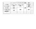
- FIG. 6 is a diagram showing an example of table data used to determine a specific abnormal state.
- the table data includes devices and information that are necessary when changing to each event and controlling the control target. For example, to transition to a lane keeping event, one or both of the radar 30-1 and the finder 20-1 and the camera 40 are required. Therefore, when there is an abnormality in either of the radar 30-1 and the finder 20-1 or in the finder 20-1, the determination unit 110 performs control in the automatic operation mode based on the action plan. Influence the result of That is, the determination unit 110 determines that the abnormal state is a specific abnormal state.
- the determination unit 110 detects an apparatus (the radar 30-1 or the finder 20-1) having an abnormality depending on the detection range of the other apparatus. It is determined that the range can be covered, and it is determined that the abnormality of the device does not affect the result of the control in the automatic driving mode based on the action plan. That is, the determination unit 110 determines that the abnormal state is not a specific abnormal state.
- the determination unit 110 determines that the abnormal state is a specific abnormal state.
- the determination unit 110 is not limited to using table data when determining a specific abnormal state, and determines a specific abnormal state by executing a program in which information equivalent to the table data is embedded. It is also good. In addition, the determination unit 110 may use map data including information equivalent to table data.
- the determination unit 110 determines that the abnormal state detected by the recognition unit 104 affects the result of the control in the automatic driving mode based on the action plan, that is, determines that the abnormal state is a specific abnormal state. In this case, the determination result is output to the change unit 112.
- the changing unit 112 is executing in control by the traveling control unit 114 among the events included in the action plan when the determining unit 110 determines that the abnormal condition detected by the recognizing unit 104 is a specific abnormal condition.
- the control content by the traveling control unit 114 is changed based on the type of the event.
- the change unit 112 determines that the abnormal state detected by the recognition unit 104 is a specific abnormal state by the determination unit 110, an event being executed in the automatic driving mode by the traveling control unit 114
- the action plan generated by the action plan generation unit 106 is changed based on the type of For example, when the event being executed in the control by the traveling control unit 114 is a predetermined event, the changing unit 112 causes the traveling control unit 114 to continue the predetermined event and is executed following the predetermined event. Prohibit the transition to the scheduled event, and change the scheduled event to be executed following the predetermined event to a deceleration event that causes the vehicle M to stop within the predetermined time T.
- the predetermined event is, for example, a lane keep event.
- a predetermined event will be described as a lane keep event, the present invention is not limited to this, and may be, for example, a lane change event or a branch event.
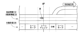
- FIG. 7 is a diagram showing a scene in which the event under execution in the control by the traveling control unit 114 is a lane keeping event.
- the broken line AP shown in FIG. 7 and in FIGS. 8 and 9 described below indicates the position (time t0) when the determination unit 110 determines that the specific abnormal state is present.
- the determination unit 110 determines that the abnormal state detected by the recognition unit 104 is a specific abnormal state.
- the change unit 112 causes the traveling control unit 114 to continue the lane keep event and prohibits an event to be executed following the lane keep event, that is, transition to a lane change, and the lane keep event
- the event scheduled to be executed subsequently is changed to a deceleration event for stopping the vehicle M within a predetermined time T.
- the vehicle control device 100 can reduce the change in the behavior of the vehicle M when detecting an abnormality that affects the control result during traveling, that is, when detecting a specific abnormal state. As a result, the vehicle control device 100 can maintain the vehicle M in a stable state.
- the change unit 112 controls the traveling control unit 114 among the events included in the action plan.
- the control content by the traveling control unit 114 is changed based on the type of the event to be executed subsequently to the event in execution.
- the change unit 112 determines whether or not the type of the event scheduled to be executed following the event being executed by the travel control unit 114 is a predetermined event (a lane keep event in the present embodiment). If the type of the scheduled event is a predetermined event, it is determined whether the predetermined event can be executed within a predetermined time T or not.
- FIG. 8 is a diagram showing a scene in which the event being executed in the control by the traveling control unit 114 is a branch event.
- the determination unit 110 determines that the abnormal state detected by the recognition unit 104 is a specific abnormal state during the branch event.
- the change unit 112 determines whether the event following the branch event is a lane keep event. As shown in FIG. 8, the change unit 112 determines that the event following the branch event is a lane keep event, and determines whether the lane keep event can be executed within a predetermined time T.
- the change unit 112 determines that the event following the branch event is a lane keep event, and determines whether the lane keep event can be executed within a predetermined time T.
- the change unit 112 determines whether the lane keeping event can be executed within the predetermined time T if the abnormal state currently detected by the recognition unit 104 is a specific abnormal state. This is performed by comparing the period from time t0 determined by the determination unit 110 to the end time t1 of the next scheduled lane keep event with the predetermined time T. For example, when the period from time t0 to time t1 is shorter than the predetermined time T, the change unit 112 can execute the lane keep event scheduled to be executed following the branch event currently being executed in the travel control unit 114.
- the predetermined time T described above is an example of the “predetermined control transition period”.
- the change unit 112 changes the lane keep event to be executed subsequently to the branch event being executed in the traveling control unit 114. It is determined that execution is possible within a predetermined time T.
- the change unit 112 determines that the lane keeping event to be executed subsequent to the event being executed in the travel control unit 114 can be executed within the predetermined time T, the change of the control content by the travel control unit 114 The processing is stopped, and the transition to the lane keeping event by the traveling control unit 114 is permitted. Therefore, the traveling control unit 114 performs a lane keeping event within the predetermined time T.
- the vehicle control device 100 can suppress unstable automatic driving for a long time under an abnormal state. As a result, the vehicle control device 100 can maintain the vehicle M in a stable state.
- the change unit 112 determines that the lane keeping event to be executed subsequent to the event being executed in the travel control unit 114 is not executable within the predetermined time T
- the automatic operation mode by the travel control unit 114 The event scheduled to be executed subsequently to the event currently being executed is changed to a deceleration event for stopping the vehicle M within a predetermined time T.
- the vehicle control device 100 can quickly stop the vehicle M when detecting a specific abnormal state that affects the control result during traveling.
- the changing unit 112 determines that the lane keeping event can not be executed within the predetermined time T
- the scheduled event is changed to a deceleration event for stopping the vehicle M within the predetermined time T.
- the change unit 112 may decelerate to a constant speed within a predetermined time T, and may be a decelerating event (progressive event) that maintains the decelerated speed.
- the event to be changed by the changing unit 112 is described as an event scheduled immediately after the currently executing event, but the present invention is not limited to this. Or you may change the scheduled event after the third one.
- the changing unit 112 follows the event being executed by the traveling control unit 114 It is determined whether or not an event scheduled to be executed can be changed to a predetermined event (lane keep event). Specifically, in response to the determination result by the determination unit 110, the change unit 112 executes following the event being executed in the traveling control unit 114 when the determination unit 110 determines that the specific abnormal state is present. It is determined whether the scheduled event is feasible even under certain abnormal conditions.
- FIG. 9 is a diagram showing a scene in which the event being executed in the control by the traveling control unit 114 is a lane change event.
- the determination unit 110 determines that the vehicle is in a specific abnormal state. Further, an event scheduled to be executed following the lane change event is set as a branch event.
- the change unit 112 refers to the determination result of the determination unit 110 and determines an abnormal state of each device and an abnormal state of communication when the determination unit 110 determines that the specific abnormal state is present.
- the determination unit 110 refers to the table data in FIG. It determines that it is a state.
- the event executed by the traveling control unit 114 is a lane keeping event, as shown in the table data of FIG. 6, while the lane keeping event is being performed by the traveling control unit 114, the radar 30 -2 Anomalous state of the radar 30-3 does not affect the result of control by the automatic operation mode based on the action plan.
- the traveling control unit 114 when the lane keeping event is executed, the vehicle is not detected as a specific abnormal state, and the vehicle is driven.
- the control result of the control unit 114 may not be affected. Therefore, when the determination unit 110 determines that the specific abnormal state is present, the change unit 112 determines whether the lane keep event can be performed or not based on the specific abnormal state, and when the change is possible. , Change the scheduled event to a lane keep event, and change the scheduled event to a deceleration event that causes the vehicle M to stop within a predetermined time T when it is not feasible.
- the change unit 112 changes the control content by the travel control unit 114 based on the type of the event being executed in the travel control unit 114 or the type of the event scheduled to be executed subsequently to the event being executed, travel control is performed
- the control switching unit 108 is controlled to switch the control mode of the unit 114 from the automatic operation mode to the manual operation mode.
- the vehicle control device 100 can hand over the control of the vehicle to the driver while the vehicle M is stable. Further, when the vehicle control apparatus 100 can compensate for the detection range of the device having an abnormality due to a failure or the like by the detection range of another device, the vehicle control device 100 does not determine that it is a specific abnormal condition affecting the control result.
- the change unit 112 changes the control content of the travel control unit 114 based on both the type of the event being executed in the travel control unit 114 and the type of the event scheduled to be executed subsequently to the event being executed. May be
- FIG. 10 is a flowchart showing an example of the process flow of the vehicle control device 100 in the present embodiment.
- the process of this flowchart is repeatedly performed in a predetermined cycle in the state where the action plan 136 has already been generated by the action plan generation unit 106.
- the control switching unit 108 switches the automatic driving mode to the manual driving mode. It is assumed that the process of switching the control mode of is performed by an interrupt.
- the control switching unit 108 determines whether the traveling control section of the vehicle M is a traveling control section in the automatic driving mode (step S100). .
- the control switching unit 108 sets the control mode of the driving control unit 114 to the automatic driving mode (step S102).
- the control switching unit 108 sets the control mode of the traveling control unit 114 to the manual operation mode (step S104), and ends the processing of this flowchart.
- the traveling control unit 114 set in the automatic driving mode controls the control target based on the event of the action plan 136 generated by the action plan generating unit 106 (step S106).
- the determination unit 110 determines whether the abnormal state detected by the recognition unit 104 is a specific abnormal state (step S108). When the abnormal state detected by the recognition unit 104 is not a specific abnormal state, that is, when a specific abnormal state is not detected, the vehicle control device 100 controls the automatic driving mode by the event currently executed by the traveling control unit 114. It is determined whether the section ends (step S110).
- the vehicle control apparatus 100 sets the control mode of the traveling control unit 114 to the manual operation mode when the control section of the automatic driving mode ends due to an event currently executed by the traveling control unit 114 (step S104). If the process of step S is ended and the control section of the automatic driving mode is not ended by the event currently executed by the traveling control unit 114, the process returns to the process of step S102.
- the change unit 112 causes the travel control unit 114 to select one of the events included in the action plan.
- the control content by the traveling control unit 114 is changed based on one or both of the type of the event being executed in control and the type of the event scheduled to be executed subsequently to the event being executed (step S200).
- the control switching unit 108 sets the control mode of the traveling control unit 114 to the manual operation mode (step S104), and ends the processing of this flowchart.
- FIG. 11 is a flowchart showing an example of the flow of control content change processing executed by the control switching unit 108 and the change unit 112 in the present embodiment.
- the process of this flowchart corresponds to the process of step S200 in the flowchart of FIG.
- the change unit 112 starts counting of the predetermined time T (step S202).
- the change unit 112 determines whether there is an event of a transition destination within the predetermined time T (step S204).
- the event of the transition destination represents an event scheduled to be executed after the event being executed in the traveling control unit 114.
- the changing unit 112 determines whether or not the event of the transition destination can be implemented (step S206). Specifically, the abnormal state of each device and the abnormal state of communication when it is determined by the determination unit 110 that there is a specific abnormal state are determined, and using the table data as shown in FIG. It is determined whether the event of the transition destination can be implemented based on the abnormal state. Note that the change unit 112 determines whether the type of the event (event of transition destination) scheduled to be executed subsequent to the event being executed by the traveling control unit 114 is a predetermined event (lane keep event in this embodiment).
- the predetermined event It may be determined whether or not the predetermined event can be executed within the predetermined time T if the type of the scheduled event (the event of the transition destination) is the predetermined event.
- the changing unit 112 starts from the time t0 determined by the determining unit 110 that the abnormal state detected by the recognition unit 104 is a specific abnormal state (the time when the process of step S108 is performed) next.
- the changing unit 112 When the event of the transition destination can be implemented, the changing unit 112 outputs warning information indicating that an abnormality has occurred (step S208). The output of the warning information is performed by, for example, the operation of the pretensioner, the operation of the audio device, the lighting of the lighting device, or the like.
- the change unit 112 causes the traveling control unit 114 to perform control based on the event of the transition destination (step S210).
- the change unit 112 determines whether control based on the event of the transition destination has been completed (step S212). Specifically, the change unit 112 determines whether the current time is the end time of the event, and when the current time is the end time of the event, the control based on the event of the transition destination is completed. If it is determined that the current time is not the end time of the event, it is determined that the control based on the event of the transition destination is not completed.
- the changing unit 112 When the control based on the event of the transition destination is not completed, the changing unit 112 returns to the process of step S210, and causes the traveling control unit 114 to continuously perform the control based on the event of the transition destination. On the other hand, when the control based on the event of the transition destination is completed, the change unit 112 determines whether the event (event of the transition destination) being executed in the traveling control unit 114 is a lane keep event (step S214). .
- the changing unit 112 is executed after the event (transition destination event) being executed in the traveling control unit 114 Prohibit the transition to the scheduled event, and change the next scheduled event to a decelerating event for stopping the vehicle M within the predetermined time T (step S220).
- the changing unit 112 can not carry out the transition destination event, or the event (transition destination event) being executed in the travel control unit 114 is a lane keep event If the determination unit 110 determines that there is a specific abnormal condition by the determination unit 110, the abnormal condition of each device and the communication abnormal condition are determined, and the vehicle is currently driven by the abnormal condition of these devices and the abnormal condition of the communication. It is determined whether the event being executed by the control unit 114 can transition to the lane keep event (step S216). If the change unit 112 can transition to the lane keep event, the process returns to the process of step S208 described above.
- the change unit 112 prohibits the event of the transition destination (step S218), and specifies an event scheduled to be executed subsequently to the event executed by the traveling control unit 114. It changes into the deceleration event which stops the vehicle M within time T (step S220), and makes the traveling control part 114 implement control based on the said deceleration event.
- the change unit 112 While the vehicle M is traveling by the control based on the deceleration event in step S220, the change unit 112 performs the vehicle M within the predetermined time T based on the detection result of the acceleration, the speed, and the like detected by the vehicle sensor 60. It is determined whether it is possible to stop (step S222). If the change unit 112 can not stop the vehicle M within the predetermined time T, the process returns to step S220, and changes again to the deceleration event for stopping the vehicle M within the predetermined time T. That is, the change unit 112 changes the content of the event so that the detection result of the vehicle sensor 60 is fed back to the control result of the deceleration event to stop the vehicle M within the predetermined time T. If the change unit 112 can stop the vehicle M within the predetermined time T, the process ends in the flowchart.
- the traveling of the vehicle M is controlled based on the action plan including the plurality of events generated by the action plan generation unit 106.
- a specific abnormal state is detected by the traveling control unit 114, the recognition unit 104 that detects a specific abnormal state (device abnormality or communication abnormality) that affects the control result of the traveling control unit 114, and the recognition unit 104
- the type of the event being executed under control by the traveling control unit 114 and the event scheduled to be executed subsequently to the event being executed is included in the action plan generated by the action plan generation unit 106.
- a change unit 112 that changes the control content by the traveling control unit 114 based on one or both of the types of Therefore, it is possible to realize a transition of the control state corresponding to the state of the vehicle.
- the changing unit 112 performs the lane keeping event when the traveling control unit 114 is in the automatic driving mode.
- the travel control unit 114 continues the lane keep event and prohibits transition to an event to be executed subsequently to the lane keep event.
- the vehicle control device 100, the vehicle control method, and the vehicle control program can reduce the change in the behavior of the vehicle M when detecting an abnormality that affects the control result during traveling.
- the vehicle control device 100, the vehicle control method, and the vehicle control program can maintain the vehicle M in a stable state.
- the vehicle control device 100, the vehicle control method, and the vehicle control program in the present embodiment there is an abnormality in the device necessary for the lane keeping event, and the detection range of the abnormal device is detected using another normal device. If it can not be covered, the changing unit 112 changes the event scheduled to be executed following the event in progress to a decelerating event for stopping within the predetermined time T. Accordingly, the vehicle control device 100, the vehicle control method, and the vehicle control program can quickly stop the vehicle M in a stable state when detecting an abnormality affecting the control result during traveling. . As a result, the vehicle control device 100, the vehicle control method, and the vehicle control program can maintain the vehicle M in a more stable state.
- the type of the event being executed in the travel control unit 114 or the event scheduled to be executed subsequently to the event being executed When the control content by the traveling control unit 114 is changed based on the type, the driver can control the vehicle by controlling the control switching unit 108 to switch the control mode of the traveling control unit 114 from the automatic driving mode to the manual driving mode. Control can be handed over smoothly.
- the traveling control unit when the detection range of the device having an abnormality due to a failure or the like can be compensated by the detection range of another device.
- the driver does not have to make corrections to the trajectory after transitioning to the manual operation mode by not determining that it is an abnormality that affects the control result of 114, and continuing without changing the originally planned action plan. It can be omitted.
- the vehicle control device 100, the vehicle control method, and the vehicle control program in the present embodiment can improve the convenience of the user such as the driver.
- the change unit 112 is scheduled to be executed following the event that the travel control unit 114 is executing within the predetermined time T.
- the travel control unit 114 determines that an event scheduled to be executed following an event being executed can be executed within a predetermined time T
- the travel control unit The change processing of the control content by 114 is stopped, and the transition to the scheduled event by the traveling control unit 114 is permitted.
- the vehicle control device 100, the vehicle control method, and the vehicle control program can perform control based on the result of appropriately determining the continuity of control based on the action plan by the travel control unit 114.
- FIG. 12 is a flowchart showing another example of the flow of control content change processing executed by the control switching unit 108 and the change unit 112 in the present embodiment.
- the process of this flowchart corresponds to the process of step S200 in the flowchart of FIG.
- the change unit 112 starts counting of the predetermined time T (step S302).
- the change unit 112 determines whether the event being executed is a lane keep event (step S304).
- the change unit 112 determines an abnormal state of each device and an abnormal state of communication when the determination unit 110 determines that the specific abnormal state is present, and It is determined whether it affects the lane keeping event (step S306). If the change unit 112 does not affect the lane keeping event being executed, the changing unit 112 determines whether or not the lane keeping event being executed can be performed within the predetermined time T (step S308).
- the changing unit 112 outputs warning information when the lane keeping event under execution can be performed within the predetermined time T (step S310), and stops the change processing of the lane keeping event under execution, and the traveling control unit 114 The control based on the lane keeping event being executed is continuously performed (step S312).
- the change unit 112 prohibits the running lane keep event if it affects the running lane keep event or if the running lane keep event can not be performed within the predetermined time T (step S 314). .
- the change unit 112 determines the abnormal state of each device and the communication abnormal state when the determination unit 110 determines that the specific abnormal state is present, and the lane keep It is determined whether it affects other events that are not being executed and in progress (step S316). If the change unit 112 does not affect the other event being executed, the change unit 112 determines whether or not the other event being executed can be performed within the predetermined time T (step S320). The changing unit 112 outputs warning information when the other event being executed can be performed within the predetermined time T (step S322), and stops the changing process of the other event being executed, and the traveling control unit 114 Control based on the other event being executed is continued (step S324). The changing unit 112 prohibits the other event being executed, when it affects the other event being executed or when the other event being executed can not be performed within the predetermined time T (step S318).
- the change unit 112 determines whether or not the event to be executed following the other event being executed (event of transition destination) is a lane keep event (step S326).
- the changing unit 112 can change the scheduled event (transition destination event) to a lane keep event if the event (transition destination event) scheduled to be executed following another event being executed is not a lane keep event. It is determined whether there is any (step S328). Specifically, the change unit 112 determines the abnormal state of each device and the abnormal state of communication when the determination unit 110 determines that the specific abnormal state is present, and whether the lane keep event is affected or not.
- the change unit 112 determines that the scheduled event can be changed to the lane keep event when it does not affect the lane keep event, and when it affects the lane keep event, the scheduled event (transition destination event ) Can not be changed to a lane keep event.
- the change unit 112 prohibits the scheduled event (transition destination event) when the scheduled event (transition destination event) can not be changed to the lane keep event (step S314).
- the change unit 112 changes the scheduled event (transition destination event) into the lane keep event. If the determination unit 110 determines that there is a specific abnormal condition by the determination unit 110, the abnormal condition of each device and the abnormal condition of communication are determined, and the event to be a lane keep event (event of transition destination) ) Is determined (step S330).
- the changing unit 112 prohibits the scheduled event (transition destination event) when affecting the scheduled event (transition destination event) that is the lane keeping event (step S314).
- the change unit 112 determines whether or not the scheduled event (transition destination event) can be performed within the predetermined time T, when the change event 112 does not affect the scheduled event (transition destination event) that is a lane keep event. (Step S332).
- the change unit 112 prohibits the scheduled event (event of transition destination) when the scheduled event (event of transition destination) can not be performed within the predetermined time T (step S314).
- the change unit 112 when it is possible to carry out the scheduled event (the transition destination event) within the predetermined time T, the change unit 112 outputs warning information (step S324), and changes the scheduled event (the transition destination event) And causes the traveling control unit 114 to continuously carry out control based on the scheduled event (event of transition destination) (step S326). That is, the change unit 112 causes the traveling control unit 114 to perform control based on the scheduled lane keep event. If the change unit 112 determines that the determination in step S328 is affirmative, the change unit 112 may skip the process of step S330 and perform the process of step S332.
- the changing unit 112 changes the event scheduled to be performed following the event being executed in the traveling control unit 114 into a deceleration event for stopping the vehicle M within the predetermined time T (step S338),
- the travel control unit 114 performs control based on the deceleration event.
- step S340 the change unit 112 performs the vehicle M within the predetermined time T based on the detection result of the acceleration, the speed, and the like detected by the vehicle sensor 60. It is determined whether it can be stopped (step S340). If the change unit 112 can not stop the vehicle M within the predetermined time T, the process returns to the process of step S338, and changes again to the deceleration event for stopping the vehicle M within the predetermined time T. That is, the change unit 112 changes the content of the event so that the detection result of the vehicle sensor 60 is fed back to the control result of the deceleration event to stop the vehicle M within the predetermined time T. If the change unit 112 can stop the vehicle M within the predetermined time T, the process ends in the flowchart.
- transition of the control state according to the state of the vehicle can be realized as in the case of performing the process of FIG. 11 and the flowchart.
Priority Applications (4)
| Application Number | Priority Date | Filing Date | Title |
|---|---|---|---|
| CN201680039724.4A CN107735302B (zh) | 2015-07-10 | 2016-06-24 | 车辆控制装置、车辆控制方法及存储车辆控制程序的介质 |
| DE112016003126.2T DE112016003126T5 (de) | 2015-07-10 | 2016-06-24 | Fahrzeug-Regel-/Steuervorrichtung, Fahrzeug-Regel-/Steuerverfahren und Fahrzeug-Regel-/Steuerprogramm |
| US15/742,122 US10940868B2 (en) | 2015-07-10 | 2016-06-24 | Vehicle control device, vehicle control method, and vehicle control program |
| JP2017528358A JP6448154B2 (ja) | 2015-07-10 | 2016-06-24 | 車両制御装置、車両制御方法、および車両制御プログラム |
Applications Claiming Priority (2)
| Application Number | Priority Date | Filing Date | Title |
|---|---|---|---|
| JP2015-138717 | 2015-07-10 | ||
| JP2015138717 | 2015-07-10 |
Publications (1)
| Publication Number | Publication Date |
|---|---|
| WO2017010264A1 true WO2017010264A1 (ja) | 2017-01-19 |
Family
ID=57757933
Family Applications (1)
| Application Number | Title | Priority Date | Filing Date |
|---|---|---|---|
| PCT/JP2016/068805 WO2017010264A1 (ja) | 2015-07-10 | 2016-06-24 | 車両制御装置、車両制御方法、および車両制御プログラム |
Country Status (5)
| Country | Link |
|---|---|
| US (1) | US10940868B2 (de) |
| JP (1) | JP6448154B2 (de) |
| CN (1) | CN107735302B (de) |
| DE (1) | DE112016003126T5 (de) |
| WO (1) | WO2017010264A1 (de) |
Cited By (15)
| Publication number | Priority date | Publication date | Assignee | Title |
|---|---|---|---|---|
| JP2017165322A (ja) * | 2016-03-17 | 2017-09-21 | 株式会社デンソー | 走行支援装置 |
| WO2018155142A1 (ja) * | 2017-02-21 | 2018-08-30 | 日立オートモティブシステムズ株式会社 | 車両制御装置 |
| WO2018198547A1 (ja) * | 2017-04-24 | 2018-11-01 | 日立オートモティブシステムズ株式会社 | 車両の電子制御装置 |
| WO2018207551A1 (ja) | 2017-05-12 | 2018-11-15 | 日立オートモティブシステムズ株式会社 | 情報処理装置及び異常対処方法 |
| WO2018216333A1 (ja) * | 2017-05-22 | 2018-11-29 | 株式会社デンソー | 電子制御装置、車両制御方法、及び車両制御用プログラム |
| CN108928347A (zh) * | 2017-05-22 | 2018-12-04 | 本田技研工业株式会社 | 自动行驶控制装置 |
| WO2019035458A1 (en) * | 2017-08-18 | 2019-02-21 | Sony Semiconductor Solutions Corporation | CONTROL DEVICE AND CONTROL SYSTEM |
| JP2019038474A (ja) * | 2017-08-28 | 2019-03-14 | 株式会社Subaru | 自動操舵システム |
| WO2019073526A1 (ja) * | 2017-10-10 | 2019-04-18 | 日産自動車株式会社 | 運転制御方法及び運転制御装置 |
| WO2019073525A1 (ja) * | 2017-10-10 | 2019-04-18 | 日産自動車株式会社 | 運転制御方法及び運転制御装置 |
| WO2020045319A1 (ja) * | 2018-08-31 | 2020-03-05 | 株式会社デンソー | 車両制御装置、方法および記憶媒体 |
| JP2020038200A (ja) * | 2018-08-31 | 2020-03-12 | 株式会社デンソー | 車両制御装置、方法および記憶媒体 |
| US11008011B2 (en) | 2017-09-28 | 2021-05-18 | Waymo Llc | Detecting and responding to propulsion and steering system errors for autonomous vehicles |
| KR20210106040A (ko) * | 2020-02-19 | 2021-08-30 | 재단법인대구경북과학기술원 | 주행경로 설정장치 및 주행경로 설정방법 |
| US11338818B2 (en) * | 2017-05-16 | 2022-05-24 | Denso Corporation | Autonomous driving assistance method and device |
Families Citing this family (34)
| Publication number | Priority date | Publication date | Assignee | Title |
|---|---|---|---|---|
| EP3159853B1 (de) * | 2015-10-23 | 2019-03-27 | Harman International Industries, Incorporated | Systeme und verfahren zur fortschrittlichen fahrerassistenzanalytik |
| US10889304B2 (en) * | 2016-02-19 | 2021-01-12 | Honda Motor Co., Ltd. | Vehicle control device, vehicle control method, and vehicle control program |
| KR20180072139A (ko) * | 2016-12-21 | 2018-06-29 | 현대자동차주식회사 | 차량 및 그 제어 방법 |
| US11731665B2 (en) * | 2017-04-12 | 2023-08-22 | Nissan Motor Co., Ltd. | Driving control method and driving control device |
| DE112017007616T5 (de) * | 2017-06-08 | 2020-05-07 | Mitsubishi Electric Corporation | Fahrzeug-Steuerungseinrichtung |
| KR20190023550A (ko) * | 2017-08-29 | 2019-03-08 | 현대자동차주식회사 | 내비게이션 정보를 이용한 주행지원시스템 및 그 동작방법 |
| US10513273B1 (en) * | 2017-09-28 | 2019-12-24 | Waymo Llc | Driver transition assistance for transitioning to manual control for vehicles with autonomous driving modes |
| WO2019167231A1 (ja) * | 2018-03-01 | 2019-09-06 | 本田技研工業株式会社 | 走行制御装置、走行制御方法およびプログラム |
| JP7199150B2 (ja) * | 2018-03-12 | 2023-01-05 | 本田技研工業株式会社 | 車両制御装置、車両制御方法、及びプログラム |
| JP7077083B2 (ja) * | 2018-03-15 | 2022-05-30 | 本田技研工業株式会社 | 表示システム、表示方法、およびプログラム |
| JP7210906B2 (ja) * | 2018-05-31 | 2023-01-24 | 株式会社デンソー | 車両の自動運転制御装置及びプログラム |
| US11937538B2 (en) * | 2018-06-21 | 2024-03-26 | Kubota Corporation | Work vehicle and grass mowing machine |
| EP3855272B1 (de) * | 2018-09-21 | 2022-11-02 | Beijing Sankuai Online Technology Co., Ltd. | Verfahren zur steuerung eines autonomen fahrzeugs und autonomes fahrzeug |
| CN109606385B (zh) * | 2018-12-05 | 2021-04-06 | 百度在线网络技术(北京)有限公司 | 一种基于自动驾驶的车辆控制方法、装置、设备和介质 |
| JP7155975B2 (ja) * | 2018-12-10 | 2022-10-19 | トヨタ自動車株式会社 | 車両制御装置 |
| JP6982564B2 (ja) * | 2018-12-27 | 2021-12-17 | 本田技研工業株式会社 | 車両制御装置 |
| JP7139964B2 (ja) | 2019-01-15 | 2022-09-21 | トヨタ自動車株式会社 | 車両制御装置及び車両制御方法 |
| JP7274117B2 (ja) | 2019-02-08 | 2023-05-16 | スズキ株式会社 | 車両の走行制御装置 |
| JP2020138600A (ja) * | 2019-02-27 | 2020-09-03 | 本田技研工業株式会社 | 車両制御システム |
| JP2020147148A (ja) * | 2019-03-13 | 2020-09-17 | トヨタ自動車株式会社 | 情報処理装置及び情報処理装置を備える自動走行制御システム |
| WO2020191708A1 (en) * | 2019-03-28 | 2020-10-01 | Baidu.Com Times Technology (Beijing) Co., Ltd. | An automatic driving safety interaction system |
| CN111845933B (zh) * | 2019-04-24 | 2023-01-10 | 奥迪股份公司 | 安全驾驶的辅助方法、装置、计算机设备和存储介质 |
| DE102020000593A1 (de) | 2020-01-30 | 2021-08-05 | Daimler Ag | Verfahren zum Betrieb eines Assistenzsystems |
| CN113264057B (zh) * | 2020-02-14 | 2022-10-11 | 宁波吉利汽车研究开发有限公司 | 一种车辆传感器状态监测方法、装置及汽车 |
| JP7446870B2 (ja) * | 2020-03-10 | 2024-03-11 | 本田技研工業株式会社 | 移動体制御装置、移動体制御方法、及びプログラム |
| JP7061148B2 (ja) * | 2020-03-31 | 2022-04-27 | 本田技研工業株式会社 | 車両制御装置、車両制御方法、およびプログラム |
| CN113641548A (zh) * | 2020-04-27 | 2021-11-12 | 北京小马智行科技有限公司 | 自动驾驶车辆的控制方法及装置、自动驾驶车辆 |
| JP7466396B2 (ja) * | 2020-07-28 | 2024-04-12 | 株式会社Soken | 車両制御装置 |
| JP7405067B2 (ja) * | 2020-12-11 | 2023-12-26 | トヨタ自動車株式会社 | 車両の制御装置、及び車両の制御方法 |
| JP7380542B2 (ja) * | 2020-12-23 | 2023-11-15 | トヨタ自動車株式会社 | 自動運転システム、及び異常判定方法 |
| JP6936380B1 (ja) * | 2020-12-28 | 2021-09-15 | 本田技研工業株式会社 | 車両制御システム、および車両制御方法 |
| CN113370996B (zh) * | 2021-07-26 | 2023-09-15 | 清华大学 | 自动驾驶换道跟驰决策方法及系统、自动驾驶车辆 |
| JP2023031746A (ja) * | 2021-08-25 | 2023-03-09 | 株式会社デンソー | アクセルペダルシステム |
| JP2023031685A (ja) * | 2021-08-25 | 2023-03-09 | 株式会社デンソー | アクセルペダルシステム |
Citations (4)
| Publication number | Priority date | Publication date | Assignee | Title |
|---|---|---|---|---|
| JPH10309961A (ja) * | 1997-05-12 | 1998-11-24 | Toyota Motor Corp | 自動走行車両制御装置 |
| JP2005165915A (ja) * | 2003-12-05 | 2005-06-23 | Mitsubishi Motors Corp | レーンキープ装置 |
| JP2008129804A (ja) * | 2006-11-20 | 2008-06-05 | Toyota Motor Corp | 走行制御計画生成システム及びコンピュータプログラム |
| JP2009274594A (ja) * | 2008-05-15 | 2009-11-26 | Hitachi Ltd | 車線変更支援装置 |
Family Cites Families (19)
| Publication number | Priority date | Publication date | Assignee | Title |
|---|---|---|---|---|
| JP3728823B2 (ja) | 1996-09-03 | 2005-12-21 | 日産自動車株式会社 | 車両用走行制御装置 |
| ES2391556T3 (es) * | 2002-05-03 | 2012-11-27 | Donnelly Corporation | Sistema de detección de objetos para vehículo |
| JP4556608B2 (ja) * | 2004-10-14 | 2010-10-06 | 日産自動車株式会社 | 車両用運転操作補助装置および車両用運転操作補助装置を備えた車両 |
| JP4466717B2 (ja) * | 2007-11-01 | 2010-05-26 | トヨタ自動車株式会社 | 走行軌跡生成方法及び走行軌跡生成装置 |
| US8229618B2 (en) * | 2008-09-11 | 2012-07-24 | Deere & Company | Leader-follower fully autonomous vehicle with operator on side |
| DE102008043220A1 (de) * | 2008-10-28 | 2010-04-29 | Robert Bosch Gmbh | Steuereinrichtung und Verfahren zur automatischen Führung eines Fahrzeugs |
| JP2012160128A (ja) | 2011-02-02 | 2012-08-23 | Toyota Motor Corp | 進路生成装置 |
| GB2492748B (en) * | 2011-07-04 | 2014-05-07 | Jaguar Land Rover Ltd | Vehicle control system and method for controlling a vehicle |
| US9147297B2 (en) * | 2012-03-14 | 2015-09-29 | Flextronics Ap, Llc | Infotainment system based on user profile |
| US8793046B2 (en) * | 2012-06-01 | 2014-07-29 | Google Inc. | Inferring state of traffic signal and other aspects of a vehicle's environment based on surrogate data |
| US9355562B1 (en) * | 2012-08-14 | 2016-05-31 | Google Inc. | Using other vehicle trajectories to aid autonomous vehicles driving through partially known areas |
| US9221396B1 (en) * | 2012-09-27 | 2015-12-29 | Google Inc. | Cross-validating sensors of an autonomous vehicle |
| US8825258B2 (en) * | 2012-11-30 | 2014-09-02 | Google Inc. | Engaging and disengaging for autonomous driving |
| KR101736306B1 (ko) * | 2013-02-27 | 2017-05-29 | 한국전자통신연구원 | 차량과 운전자간 협력형 자율 주행 장치 및 방법 |
| US8676431B1 (en) * | 2013-03-12 | 2014-03-18 | Google Inc. | User interface for displaying object-based indications in an autonomous driving system |
| US10026130B1 (en) * | 2014-05-20 | 2018-07-17 | State Farm Mutual Automobile Insurance Company | Autonomous vehicle collision risk assessment |
| US9428194B2 (en) * | 2014-12-11 | 2016-08-30 | Toyota Motor Engineering & Manufacturing North America, Inc. | Splash condition detection for vehicles |
| DE102015004550A1 (de) * | 2015-04-08 | 2016-10-13 | Audi Ag | Verfahren zum Betreiben eines Kraftfahrzeugs und Kraftfahrzeug |
| JP2018180594A (ja) * | 2017-04-03 | 2018-11-15 | 株式会社デンソー | 走行支援装置 |
-
2016
- 2016-06-24 CN CN201680039724.4A patent/CN107735302B/zh active Active
- 2016-06-24 WO PCT/JP2016/068805 patent/WO2017010264A1/ja active Application Filing
- 2016-06-24 US US15/742,122 patent/US10940868B2/en active Active
- 2016-06-24 DE DE112016003126.2T patent/DE112016003126T5/de active Pending
- 2016-06-24 JP JP2017528358A patent/JP6448154B2/ja active Active
Patent Citations (4)
| Publication number | Priority date | Publication date | Assignee | Title |
|---|---|---|---|---|
| JPH10309961A (ja) * | 1997-05-12 | 1998-11-24 | Toyota Motor Corp | 自動走行車両制御装置 |
| JP2005165915A (ja) * | 2003-12-05 | 2005-06-23 | Mitsubishi Motors Corp | レーンキープ装置 |
| JP2008129804A (ja) * | 2006-11-20 | 2008-06-05 | Toyota Motor Corp | 走行制御計画生成システム及びコンピュータプログラム |
| JP2009274594A (ja) * | 2008-05-15 | 2009-11-26 | Hitachi Ltd | 車線変更支援装置 |
Cited By (43)
| Publication number | Priority date | Publication date | Assignee | Title |
|---|---|---|---|---|
| JP2017165322A (ja) * | 2016-03-17 | 2017-09-21 | 株式会社デンソー | 走行支援装置 |
| CN110290997A (zh) * | 2017-02-21 | 2019-09-27 | 日立汽车系统株式会社 | 车辆控制装置 |
| JPWO2018155142A1 (ja) * | 2017-02-21 | 2019-07-11 | 日立オートモティブシステムズ株式会社 | 車両制御装置 |
| CN110290997B (zh) * | 2017-02-21 | 2022-06-17 | 日立安斯泰莫株式会社 | 车辆控制装置 |
| WO2018155142A1 (ja) * | 2017-02-21 | 2018-08-30 | 日立オートモティブシステムズ株式会社 | 車両制御装置 |
| US11124200B2 (en) | 2017-02-21 | 2021-09-21 | Hitachi Automotive Systems, Ltd. | Vehicle control device |
| JP2018184021A (ja) * | 2017-04-24 | 2018-11-22 | 日立オートモティブシステムズ株式会社 | 車両の電子制御装置 |
| US11352019B2 (en) | 2017-04-24 | 2022-06-07 | Hitachi Astemo, Ltd. | Electronic control device for vehicle |
| WO2018198547A1 (ja) * | 2017-04-24 | 2018-11-01 | 日立オートモティブシステムズ株式会社 | 車両の電子制御装置 |
| CN110536821A (zh) * | 2017-04-24 | 2019-12-03 | 日立汽车系统株式会社 | 车辆的电子控制装置 |
| CN110536821B (zh) * | 2017-04-24 | 2022-08-02 | 日立安斯泰莫株式会社 | 车辆的电子控制装置 |
| WO2018207551A1 (ja) | 2017-05-12 | 2018-11-15 | 日立オートモティブシステムズ株式会社 | 情報処理装置及び異常対処方法 |
| US11338818B2 (en) * | 2017-05-16 | 2022-05-24 | Denso Corporation | Autonomous driving assistance method and device |
| US11897488B2 (en) | 2017-05-16 | 2024-02-13 | Denso Corporation | Autonomous driving assistance method and device |
| JP2018195253A (ja) * | 2017-05-22 | 2018-12-06 | 本田技研工業株式会社 | 自動走行制御装置 |
| CN108928347B (zh) * | 2017-05-22 | 2021-09-03 | 本田技研工业株式会社 | 自动行驶控制装置 |
| JP2018195246A (ja) * | 2017-05-22 | 2018-12-06 | 株式会社デンソー | 電子制御装置 |
| CN110636962A (zh) * | 2017-05-22 | 2019-12-31 | 株式会社电装 | 电子控制装置、车辆控制方法、以及车辆控制用程序 |
| CN108928347A (zh) * | 2017-05-22 | 2018-12-04 | 本田技研工业株式会社 | 自动行驶控制装置 |
| WO2018216333A1 (ja) * | 2017-05-22 | 2018-11-29 | 株式会社デンソー | 電子制御装置、車両制御方法、及び車両制御用プログラム |
| EP3632761A4 (de) * | 2017-05-22 | 2020-06-10 | Denso Corporation | Elektronische steuerungsvorrichtung, fahrzeugsteuerungsverfahren und fahrzeugsteuerungsprogramm |
| CN110636962B (zh) * | 2017-05-22 | 2022-08-23 | 株式会社电装 | 电子控制装置、车辆控制方法、以及存储装置 |
| US11613263B2 (en) | 2017-05-22 | 2023-03-28 | Denso Corporation | Electronic control device, vehicle control method, non-transitory tangible computer readable storage medium |
| JP2019034664A (ja) * | 2017-08-18 | 2019-03-07 | ソニーセミコンダクタソリューションズ株式会社 | 制御装置および制御システム |
| WO2019035458A1 (en) * | 2017-08-18 | 2019-02-21 | Sony Semiconductor Solutions Corporation | CONTROL DEVICE AND CONTROL SYSTEM |
| US11853074B2 (en) | 2017-08-18 | 2023-12-26 | Sony Semiconductor Solutions Corporation | Control device and control system |
| JP2019038474A (ja) * | 2017-08-28 | 2019-03-14 | 株式会社Subaru | 自動操舵システム |
| US11008011B2 (en) | 2017-09-28 | 2021-05-18 | Waymo Llc | Detecting and responding to propulsion and steering system errors for autonomous vehicles |
| CN111448596A (zh) * | 2017-10-10 | 2020-07-24 | 日产自动车株式会社 | 驾驶控制方法以及驾驶控制装置 |
| US11458963B2 (en) | 2017-10-10 | 2022-10-04 | Nissan Motor Co., Ltd. | Driving control method and driving control apparatus |
| RU2744018C1 (ru) * | 2017-10-10 | 2021-03-02 | Ниссан Мотор Ко., Лтд. | Способ управления вождением и оборудование управления вождением |
| JPWO2019073526A1 (ja) * | 2017-10-10 | 2020-10-22 | 日産自動車株式会社 | 運転制御方法及び運転制御装置 |
| RU2743683C1 (ru) * | 2017-10-10 | 2021-02-24 | Ниссан Мотор Ко., Лтд. | Способ управления вождением и оборудование управления вождением |
| US11584388B2 (en) | 2017-10-10 | 2023-02-21 | Nissan Motor Co., Ltd. | Driving control method and driving control apparatus |
| CN111448597B (zh) * | 2017-10-10 | 2022-06-10 | 日产自动车株式会社 | 驾驶控制方法以及驾驶控制装置 |
| CN111448597A (zh) * | 2017-10-10 | 2020-07-24 | 日产自动车株式会社 | 驾驶控制方法以及驾驶控制装置 |
| WO2019073525A1 (ja) * | 2017-10-10 | 2019-04-18 | 日産自動車株式会社 | 運転制御方法及び運転制御装置 |
| WO2019073526A1 (ja) * | 2017-10-10 | 2019-04-18 | 日産自動車株式会社 | 運転制御方法及び運転制御装置 |
| WO2020045319A1 (ja) * | 2018-08-31 | 2020-03-05 | 株式会社デンソー | 車両制御装置、方法および記憶媒体 |
| JP2020038200A (ja) * | 2018-08-31 | 2020-03-12 | 株式会社デンソー | 車両制御装置、方法および記憶媒体 |
| JP7067536B2 (ja) | 2018-08-31 | 2022-05-16 | 株式会社デンソー | 車両制御装置、方法および記憶媒体 |
| KR20210106040A (ko) * | 2020-02-19 | 2021-08-30 | 재단법인대구경북과학기술원 | 주행경로 설정장치 및 주행경로 설정방법 |
| KR102366073B1 (ko) | 2020-02-19 | 2022-02-21 | 재단법인대구경북과학기술원 | 주행경로 설정장치 및 주행경로 설정방법 |
Also Published As
| Publication number | Publication date |
|---|---|
| JPWO2017010264A1 (ja) | 2018-04-12 |
| JP6448154B2 (ja) | 2019-01-09 |
| US20180194364A1 (en) | 2018-07-12 |
| US10940868B2 (en) | 2021-03-09 |
| DE112016003126T5 (de) | 2018-03-22 |
| CN107735302A (zh) | 2018-02-23 |
| CN107735302B (zh) | 2020-10-16 |
Similar Documents
| Publication | Publication Date | Title |
|---|---|---|
| JP6448154B2 (ja) | 車両制御装置、車両制御方法、および車両制御プログラム | |
| JP6380766B2 (ja) | 車両制御装置、車両制御方法、および車両制御プログラム | |
| JP6344695B2 (ja) | 車両制御装置、車両制御方法、および車両制御プログラム | |
| JP6288859B2 (ja) | 車両制御装置、車両制御方法、および車両制御プログラム | |
| US10583833B2 (en) | Vehicle control apparatus, vehicle control method, and vehicle control program | |
| JP6623501B2 (ja) | 車両制御装置、車両制御方法、および車両制御プログラム | |
| US10220847B2 (en) | Vehicle control apparatus, vehicle control method, and vehicle control program | |
| JP6713530B2 (ja) | 車両制御装置、車両制御方法、および車両制御プログラム | |
| CN108698608B (zh) | 车辆控制系统、车辆控制方法及存储介质 | |
| JP6537208B2 (ja) | 車両制御装置、車両制御方法、および車両制御プログラム | |
| WO2017141788A1 (ja) | 車両制御装置、車両制御方法、および車両制御プログラム | |
| WO2017138517A1 (ja) | 車両制御システム、車両制御方法、および車両制御プログラム | |
| WO2017158731A1 (ja) | 車両制御システム、車両制御方法、および車両制御プログラム | |
| JP6645649B2 (ja) | 車両制御装置、車両制御方法、および車両制御プログラム | |
| JP6304504B2 (ja) | 車両制御装置、車両制御方法、および車両制御プログラム | |
| JPWO2017138513A1 (ja) | 車両制御装置、車両制御方法、および車両制御プログラム | |
| JP2017081425A (ja) | 車両制御装置、車両制御方法、および車両制御プログラム | |
| JP2017081421A (ja) | 車両制御装置、車両制御方法、および車両制御プログラム |
Legal Events
| Date | Code | Title | Description |
|---|---|---|---|
| 121 | Ep: the epo has been informed by wipo that ep was designated in this application |
Ref document number: 16824244 Country of ref document: EP Kind code of ref document: A1 |
|
| ENP | Entry into the national phase |
Ref document number: 2017528358 Country of ref document: JP Kind code of ref document: A |
|
| WWE | Wipo information: entry into national phase |
Ref document number: 112016003126 Country of ref document: DE |
|
| 122 | Ep: pct application non-entry in european phase |
Ref document number: 16824244 Country of ref document: EP Kind code of ref document: A1 |