WO2016204032A1 - 紙製リール - Google Patents
紙製リール Download PDFInfo
- Publication number
- WO2016204032A1 WO2016204032A1 PCT/JP2016/067012 JP2016067012W WO2016204032A1 WO 2016204032 A1 WO2016204032 A1 WO 2016204032A1 JP 2016067012 W JP2016067012 W JP 2016067012W WO 2016204032 A1 WO2016204032 A1 WO 2016204032A1
- Authority
- WO
- WIPO (PCT)
- Prior art keywords
- blade
- pieces
- locking
- winding drum
- piece
- Prior art date
Links
- 238000004804 winding Methods 0.000 claims abstract description 87
- 238000005452 bending Methods 0.000 claims abstract description 11
- 210000002105 tongue Anatomy 0.000 claims description 30
- 238000003780 insertion Methods 0.000 claims description 21
- 230000037431 insertion Effects 0.000 claims description 21
- 239000000123 paper Substances 0.000 description 14
- 239000011111 cardboard Substances 0.000 description 8
- 230000003014 reinforcing effect Effects 0.000 description 5
- 230000003993 interaction Effects 0.000 description 2
- 238000000034 method Methods 0.000 description 2
- 239000011087 paperboard Substances 0.000 description 2
- 238000005192 partition Methods 0.000 description 2
- 229920003002 synthetic resin Polymers 0.000 description 2
- 239000000057 synthetic resin Substances 0.000 description 2
- 241000201246 Cycloloma atriplicifolium Species 0.000 description 1
- 239000000853 adhesive Substances 0.000 description 1
- 230000001070 adhesive effect Effects 0.000 description 1
- 239000000470 constituent Substances 0.000 description 1
- 230000007423 decrease Effects 0.000 description 1
- 230000000694 effects Effects 0.000 description 1
- 238000010030 laminating Methods 0.000 description 1
- 238000004519 manufacturing process Methods 0.000 description 1
- 230000000717 retained effect Effects 0.000 description 1
- 229920003051 synthetic elastomer Polymers 0.000 description 1
- 239000005061 synthetic rubber Substances 0.000 description 1
Images


Classifications
-
- B—PERFORMING OPERATIONS; TRANSPORTING
- B65—CONVEYING; PACKING; STORING; HANDLING THIN OR FILAMENTARY MATERIAL
- B65H—HANDLING THIN OR FILAMENTARY MATERIAL, e.g. SHEETS, WEBS, CABLES
- B65H75/00—Storing webs, tapes, or filamentary material, e.g. on reels
- B65H75/02—Cores, formers, supports, or holders for coiled, wound, or folded material, e.g. reels, spindles, bobbins, cop tubes, cans, mandrels or chucks
- B65H75/04—Kinds or types
- B65H75/08—Kinds or types of circular or polygonal cross-section
- B65H75/14—Kinds or types of circular or polygonal cross-section with two end flanges
-
- B—PERFORMING OPERATIONS; TRANSPORTING
- B65—CONVEYING; PACKING; STORING; HANDLING THIN OR FILAMENTARY MATERIAL
- B65H—HANDLING THIN OR FILAMENTARY MATERIAL, e.g. SHEETS, WEBS, CABLES
- B65H75/00—Storing webs, tapes, or filamentary material, e.g. on reels
- B65H75/02—Cores, formers, supports, or holders for coiled, wound, or folded material, e.g. reels, spindles, bobbins, cop tubes, cans, mandrels or chucks
- B65H75/18—Constructional details
- B65H75/20—Skeleton construction, e.g. formed of wire
-
- B—PERFORMING OPERATIONS; TRANSPORTING
- B65—CONVEYING; PACKING; STORING; HANDLING THIN OR FILAMENTARY MATERIAL
- B65H—HANDLING THIN OR FILAMENTARY MATERIAL, e.g. SHEETS, WEBS, CABLES
- B65H75/00—Storing webs, tapes, or filamentary material, e.g. on reels
- B65H75/02—Cores, formers, supports, or holders for coiled, wound, or folded material, e.g. reels, spindles, bobbins, cop tubes, cans, mandrels or chucks
- B65H75/18—Constructional details
- B65H75/22—Constructional details collapsible; with removable parts
- B65H75/2218—Collapsible hubs
-
- B—PERFORMING OPERATIONS; TRANSPORTING
- B65—CONVEYING; PACKING; STORING; HANDLING THIN OR FILAMENTARY MATERIAL
- B65H—HANDLING THIN OR FILAMENTARY MATERIAL, e.g. SHEETS, WEBS, CABLES
- B65H75/00—Storing webs, tapes, or filamentary material, e.g. on reels
- B65H75/02—Cores, formers, supports, or holders for coiled, wound, or folded material, e.g. reels, spindles, bobbins, cop tubes, cans, mandrels or chucks
- B65H75/18—Constructional details
- B65H75/22—Constructional details collapsible; with removable parts
- B65H75/2245—Constructional details collapsible; with removable parts connecting flange to hub
-
- B—PERFORMING OPERATIONS; TRANSPORTING
- B65—CONVEYING; PACKING; STORING; HANDLING THIN OR FILAMENTARY MATERIAL
- B65H—HANDLING THIN OR FILAMENTARY MATERIAL, e.g. SHEETS, WEBS, CABLES
- B65H75/00—Storing webs, tapes, or filamentary material, e.g. on reels
- B65H75/02—Cores, formers, supports, or holders for coiled, wound, or folded material, e.g. reels, spindles, bobbins, cop tubes, cans, mandrels or chucks
- B65H75/18—Constructional details
- B65H75/22—Constructional details collapsible; with removable parts
- B65H75/2254—Constructional details collapsible; with removable parts with particular joining means for releasably connecting parts
- B65H75/229—Bendable tabs being deformable over a cooperating surface
-
- B—PERFORMING OPERATIONS; TRANSPORTING
- B65—CONVEYING; PACKING; STORING; HANDLING THIN OR FILAMENTARY MATERIAL
- B65H—HANDLING THIN OR FILAMENTARY MATERIAL, e.g. SHEETS, WEBS, CABLES
- B65H2701/00—Handled material; Storage means
- B65H2701/50—Storage means for webs, tapes, or filamentary material
- B65H2701/51—Cores or reels characterised by the material
- B65H2701/511—Cores or reels characterised by the material essentially made of sheet material
- B65H2701/5112—Paper or plastic sheet material
-
- B—PERFORMING OPERATIONS; TRANSPORTING
- B65—CONVEYING; PACKING; STORING; HANDLING THIN OR FILAMENTARY MATERIAL
- B65H—HANDLING THIN OR FILAMENTARY MATERIAL, e.g. SHEETS, WEBS, CABLES
- B65H2701/00—Handled material; Storage means
- B65H2701/50—Storage means for webs, tapes, or filamentary material
- B65H2701/51—Cores or reels characterised by the material
- B65H2701/513—Cores or reels characterised by the material assembled mainly from rigid elements of the same kind
Definitions
- the present invention relates to a paper reel used for winding a flexible linear body such as a tube, a hose or an electric wire.
- Paper reels used for winding flexible linear bodies such as tubes, hoses or electric wires are well known, as disclosed, for example, in Patent Documents 1-4.
- This reel is formed of paper such as cardboard or cardboard, and includes a cylindrical winding drum for winding the wire and flange plates attached to both ends in the axial direction of the winding drum. It has the advantage of being easy to dispose of after use, but because the strength of the winding drum and shaft core is weak, various measures have been taken to increase the strength. .
- the strength is enhanced by forming the winding drum into an inner and outer double structure, and in the reel disclosed in Patent Literature 2, the inner central position of the winding drum is disclosed. Then, a plurality of annular reinforcing plates are fitted, and the reinforcing plates support the winding drum from the inside.
- a corrugated cardboard is bent to form a square hollow support member, and the support member is inserted into the inside of a cylindrical winding drum and supported from the inside. The strength of the winding drum is enhanced.
- a plurality of annular reinforcing partition plates are fitted on the outer periphery of a cylindrical shaft core while maintaining a constant distance, and the outer periphery of this reinforcing partition plate is fitted It is formed by winding a cylindrical reinforcing shaft core.
- the strength of the winding drum is considered to be greater than that of the reel disclosed in Patent Document 1-3, but it is formed separately including the shaft core. Since the winding drum is formed by combining a large number of parts, there is a disadvantage that the structure is complicated and the assembling operation is also complicated.
- the technical problem of the present invention is to provide a paper reel having a greater strength of the winding drum and the shaft core as compared with the conventional reel, and a simple structure and easy assembly.
- the reel according to the present invention comprises an impeller-like paper winding drum for winding a flexible linear body, and one end and the other end of the winding drum in the axial direction.
- the wind roller having a hollow shaft core and a plurality of blades extending radially from the outer periphery of the shaft core;
- the part core and the blade part are integrally formed by bending a sheet in which a shaft piece forming the shaft part core and a pair of blade pieces forming the blade part are alternately cut.
- the shaft core is formed in a hollow shape by arranging the shaft pieces such that adjacent shaft pieces abut each other around the axis, and the blade portion is formed of the pair of shaft portions.
- the width of the shaft piece is smaller than the height of the blade portion extending from the shaft core, and the diameter of the virtual circumscribed circle circumscribing the shaft core is also larger than the height of the blade portion It is desirable to be small.
- the pair of blade pieces forming the blade portion is held in an overlapping state by locking the tongue piece formed on at least one blade piece to the other blade piece.
- the tongue pieces are formed at mutually opposing positions of the pair of blade pieces, and the tongue pieces of the pair of blade pieces are bent to one side of one of the blade pieces in a state of overlapping each other. Therefore, the tongue piece of one blade piece is locked to the other blade piece and the pair of blade pieces are held in an overlapping state, and more preferably, the tongue piece is the blade portion Are formed at multiple locations.
- the locking pieces are respectively formed at both end portions of the pair of blade pieces, and each have a locking portion at the tip, and the flange plate has a proximal end of the locking piece.
- An insertion hole into which a portion is inserted and a locking hole into which the locking portion is inserted are alternately formed around the axis, and a locking piece of the blade piece is inserted into the insertion hole of the flange plate. After being inserted from the inside to the outside of the flange plate, it is bent in the direction of the locking hole, and the locking portion at the tip of the locking piece is inward from the outside of the flange plate to the locking hole. By being oriented, the winding drum and the flange plate are connected to each other.
- the insertion holes and the locking holes of the flange plate are formed in the same number and the same number as the number of the blade portions, and the base ends of two locking pieces formed on a pair of blade pieces in the blade portion
- the parts are inserted together into one of the insertion holes in a mutually overlapping state, and the locking portions at the tips of the two locking pieces are one in the locking holes located on both sides of the insertion hole. It is desirable to insert separately one by one and together with the locking portion of the locking piece formed on one of the pair of blade pieces in the adjacent blade portion.
- a paper cylinder may be attached to the outer periphery of the winding drum so as to surround the tips of the plurality of blade portions.
- the winding drum of the reel is in the shape of an impeller and has a plurality of blade portions extending in the radial direction from the central hollow shaft core, and a linear shape is provided so as to surround this blade portion. Because the body is wound up, the strength against the tightening force of the linear body is much greater than that of the conventional reel in which the winding drum is cylindrical, and there is no risk of deformation.
- the shaft core and the blade unit integrally form a single sheet by alternately bending a shaft piece forming the shaft core and a pair of blade pieces forming the blade unit. Since it is formed, the structure is simple and the assembly is easy as compared with the case where a plurality of parts formed individually are combined to form a reel.
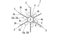
- FIG. 1 is a perspective view showing a first embodiment of a paper reel according to the present invention. It is an expanded sectional view of FIG. It is an expanded view of the sheet
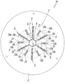
- FIG. 1 It is a perspective view which shows the state which inserted each locking piece of the end of a winding drum in each insertion hole of a flange board.
- the perspective view which shows the state which inserted separately the latching
- FIGS. 1 to 12 show a first embodiment of a paper reel according to the present invention.
- the reel 1A according to the first embodiment includes an impeller-like winding drum 2 for winding a flexible linear member such as a tube, a hose or an electric wire, and one end of the winding drum 2 in the axis L direction. And the flange plate 3 attached to the other end.
- the winding drum 2 and the flange plate 3 are formed of paper such as cardboard or cardboard, and in the present embodiment, cardboard is used as the paper.
- This corrugated board is obtained by laminating flat paper boards on both sides of a corrugated core paper, and usually has a thickness of about 3-4 mm.
- the winding drum 2 extends radially at equal angles from the outer periphery of the shaft core 4 and the hollow shaft core 4 surrounding the center hole 6.
- a plurality of plate-like blade portions 5 are provided, and the blade portions 5 are continuously provided parallel to the axis L along the axis L on the outer periphery of the shaft core 4, and the shaft core 4 Extends over the entire length of the
- the shaft core 4 and the blade portion 5 are integrally formed by bending a sheet 8 obtained by cutting a cardboard into a shape as shown in FIG.
- the sheet 8 is formed by folding a long and thin rectangular shaft piece 4 a forming a part of the outer periphery of the shaft core 4 and a pair of rectangular blade pieces 5 a and 5 b forming the blade portion 5.
- 10a, 10b, 10c are alternately arranged in plural pieces, and when one of the pair of blade pieces 5a, 5b is the first blade piece 5a and the other is the second blade piece 5b, The shaft piece 4a and the first blade piece 5a are connected via the fold line 10a, and the first blade piece 5a and the second blade piece 5b are connected via the fold line 10b, and the second blade piece 5b and The aspect in which the shaft piece 4a is continuous with the folding line 10c is sequentially repeated a plurality of times.
- a pair of blade pieces 5 a and 5 b forming one of the blade portions 5 is two. It is separated and connected separately one by one. That is, the second sheet piece 5b is continuously provided at the first end 8a of the sheet 8, and the first sheet piece 5a is continuously provided at the second end 8b of the sheet 8.
- the width W5 of the blade pieces 5a and 5b is larger than the width W4 of the shaft piece 4a, and in the illustrated example, is about three times the width W4 of the shaft piece 4a.
- locking pieces 12a and 12b are continuously provided via folding lines 11a and 11b at both end portions of the pair of blade pieces 5a and 5b in the longitudinal direction (axis L direction), respectively.
- tip-shaped tongue pieces 15a and 15b surrounded by a substantially C-shaped cut 16 are formed.
- the tongue pieces 15a and 15b are provided at a plurality of places (two places in the drawing) in the direction along the axis L, but the forming position is arbitrary, and may be one place.
- the locking pieces 12a and 12b are formed in such a manner that the width gradually decreases with distance from the blade pieces 5a and 5b, and the locking portions 13a and 13b are formed at the tips thereof at the folding lines 11a and 11b. It is continuously provided diagonally via the fold lines 14a and 14b which incline with respect to it.
- the direction in which the locking portions 13a and 13b are inclined is the direction in which the locking portions 13a and 13b of the pair of blade pieces 5a and 5b separate from each other.
- the locking portions 13a and 13b are parts of the locking pieces 12a and 12b.
- the pair of blade pieces 5a and 5b have the same shape including the tongue pieces 15a and 15b and the locking pieces 12a and 12b, and accordingly, the position of the pair of blade pieces 5a and 5b at the folding line 10b When folded in two, the whole overlaps exactly.
- the flange plate 3 has a circular shape as shown in FIG. 4, and a circular central hole 7 for inserting a reel support bar at its center leads to the central hole 6 of the winding drum 2 Slit-like insertion holes 20 into which the proximal end portions of the locking pieces 12a and 12b are inserted, and a slit-like shape into which the locking portions 13a and 13b are inserted.
- the locking holes 21 are formed alternately and radially at equal central angles around the central hole 7 (axis L).
- the length of the insertion hole 20 is substantially the same as the width of the proximal end of the locking pieces 12a and 12b, and the length of the locking hole 21 is substantially the same as the width of the locking portions 13a and 13b. Same length.
- the length of the insertion hole 20 is longer than the length of the locking hole 21.
- the number of the insertion holes 20 and the number of the locking holes 21 are the same as each other and the same as the number of the blade portions 5, and are six in the illustrated example.
- the reel 1A is formed by the sheet 8 and the flange plates 3 and 3 as follows. That is, first, as shown in FIG. 5, the pair of blade pieces 5a and 5b of the sheet 8 are double folded by bending at the position of the folding line 10b, and the blade pieces 5a and 5b are It is bent at the position of the folding lines 10a and 10c to stand up to the shaft piece 4a. Then, the tongue pieces 15a and 15b of the pair of folded blade pieces 5a and 5b are bent toward one of the blade pieces 5a or 5b while overlapping with each other, thereby the pair of blade pieces Hold 5a and 5b in an overlapping state. In the illustrated example, the tongue pieces 15a and 15b are bent toward the second blade piece 5b.
- the second tongue pieces 15a and 15b are overlapped with each other.
- the tongue piece 15a of the first blade piece 5a is fitted in the notch 16 of the second blade piece 5b and locked to the notch 16, thereby the pair of blade pieces 5a, 5a, The 5b will be held in an overlapping state. If the two tongues 15a and 15b are folded on the outer surface side of the one blade piece 5a or 5b, the locking effect on the cut 16 is further improved.
- both blade pieces 5a and 5b are superimposed on each other, and the tongue pieces 15a and 15b of both blade pieces 5a and 5b are kept in a state of being superimposed on each other.
- the pair of blade pieces 5a and 5b are held in an overlapping state by bending them to the 5b side and locking them in the cut 16.
- an impeller-like winding drum 2 as shown in FIGS. 6 and 7 is formed.
- the shaft core 4 and the blade portion 5 are integrally formed by bending a sheet of the sheet 8, a plurality of separately formed parts are combined and wound.
- the configuration is simple and the assembly is easy.
- the shaft core 4 is arranged in a regular hexagonal shape by arranging six shaft pieces 4 a around the axis L in a state where adjacent shaft pieces 4 a are in contact with each other.
- the center hole 6 is also formed in a regular hexagonal shape, the shaft core 4 may be formed in a cylindrical shape by bending the shaft piece 4a outward in a convex arc shape. it can. At this time, the central hole 6 also becomes a circular hole.
- the width W5 of the blade pieces 5a and 5b is larger than the width W4 of the shaft piece 4a (see FIG. 3), the height H at which the blade portion 5 extends from the shaft portion core 4 is , The diameter of the shaft core 4 is larger.
- the diameter of the virtual circumscribed circle C is smaller than the height H of the blade portion 5, and in the illustrated example, The diameter of the virtual circumscribed circle C is about 3 ⁇ 5 of the height H of the blade portion 5.
- the shaft core 4 Since the shaft core 4 is formed in this manner, the strength of the plurality of shaft pieces 4a becomes very large due to the interaction of the shaft pieces 4a. That is, even when a winding pressure is applied to the shaft core 4 through the blade unit 5 when the linear body is wound around the winding drum 2, adjacent shaft pieces 4a support each other, The shaft core 4 is not recessed toward the center of the hollow portion at the position of the blade 5, and as a result, deformation and crushing of the shaft core 4 are reliably prevented.
- the flange plate 3 is sequentially attached to one end and the other end of the winding drum 2 in the direction of the axis L.
- the attachment is performed as shown in FIGS.
- each insertion hole 20 of the flange plate 3 the base end portions of the two locking pieces 12 a and 12 b of the pair of blade pieces 5 a and 5 b in the blade portion 5 are together.
- locking portions 13a and 13b of the first blade piece 5a and the second blade piece 5b of two adjacent blade portions 5 connected via the shaft pieces 4a are, It is inserted together.
- the flange plate 3 is attached to both ends of the winding drum 2 by attaching the flange plate 3 to the other end of the winding drum 2 in the same manner.
- the reel 1A assembled in this manner is, for example, a coil of a linear body manufactured at the time of manufacturing a flexible linear body such as a synthetic resin or rubber tube or hose used for an air pipe or the like.
- the linear body is wound around the plurality of blade portions 5 so as to be used for picking.
- the wound linear body is transported to a factory or the like and fed out sequentially from the reel and used.
- the reel 1A is discarded.
- a support bar can be inserted into the center holes 6 and 7 of the reel 1A, and the reel 1A can be rotatably supported by the support bar.
- the reel 1 ⁇ / b> A configured in this way has a plurality of blade portions 5 in which the winding drum 2 is shaped like an impeller and extends in the radial direction from the central shaft core 4. Since the above-mentioned linear body is wound up so as to surround the above, the strength against the winding pressure of the linear body is much greater than that of the conventional reel in which the winding drum is cylindrical, and there is a fear of causing deformation or breakage. Absent.
- the blade portion 5 is formed by double folding a pair of plate-like blade pieces 5a and 5b and holding them in a folded state by the tongue pieces 15a and 15b, the rigidity is increased.
- the blade pieces 5a and 5b which are very large and further folded, are inserted together into one insertion hole 20 of the flange plate 3 in a state where the locking pieces 12a and 12b overlap each other, and the locking pieces 12a , 12b are separately inserted into and locked in the two locking holes 21 on both sides of the insertion hole 20, so that they securely contact each other. It will be retained, which will lead to an increase in further support.
- the shaft core 4 is formed so as to surround the axis L in a state in which the plurality of shaft pieces 4 a are in contact with each other, a winding pressure acting through the blade portion 5 can be reduced. On the other hand, the interaction between the adjacent shaft pieces 4a exerts a large strength. For this reason, as described above, when the support rod is inserted into the center hole 6 of the shaft core 4 and used when the linear body is wound up or unwound, the shaft core 4 is used. It will not be damaged.
- blade portions 5 of the winding drum 2 are formed, but the number of the blade portions 5 may be other than six as long as it is three or more. .
- the tongue pieces 15a and 15b are formed at opposite positions of the pair of blade pieces 5a and 5b forming the blade portion 5, but a tongue piece is formed on one of the blade pieces. And the other blade piece is formed with a locking hole, and the tongue piece is inserted into the locking hole and locked thereby to lock the pair of blade pieces with each other. it can.
- tongues and locking holes are formed at different positions of any one of the blade pieces, and locking holes and tongues are formed at positions corresponding to the tongues and locking holes of the other blade pieces. It is also possible for the tongues and the locking holes of both blade pieces to be locked to one another.
- the left and right flange plates 3 use a corrugated board having a strength greater than that of the corrugated board forming the winding drum 2, or a plurality of flange boards 3 of the same configuration (for example, a method of using two sheets in an overlapping manner can be used.
- the stacked flange plates may be fixed to each other by an adhesive or the like.
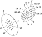
- FIGS. 13 and 14 show a second embodiment of the paper reel according to the present invention.
- the difference between the reel 1B of the second embodiment and the reel 1A of the first embodiment is that it has an impeller shape.
- the paper cylinder 25 is attached to the outer periphery of the winding drum 2 so as to surround the tips of the plurality of blade portions 5.
- the other configuration is the same as that of the reel 1A of the first embodiment, including the modified examples and the like, so the same reference numerals as those of the reel 1A of the first embodiment are attached to the same main constituent parts of both. Is omitted.
- the cylindrical body 25 is formed by rounding a flat paper board having a thickness of about 1 mm into a cylindrical shape, and the axial L direction of the cylindrical body 25 is the axial L direction of the blade portion 5 of the winding drum 2 It is about the same as the length of
- the cylinder 25 is attached to the reel 1A by assembling the winding drum 2 and attaching one flange plate 3 to one end of the winding cylinder 2. Then, from the other end of the winding drum 2 to the outer periphery of the blade 5, the cylinder Then, the other flange plate 3 may be attached to the other end of the winding drum 2. However, after the reel 1A as shown in FIG. 1 is assembled, the cylindrical body 25 can be formed by winding a flat paper sheet around the outer periphery of the winding drum 2.
- the inner diameter of the cylindrical body 25 may be substantially the same as the diameter of an imaginary circle in contact with the tips of the plurality of blade portions 5, but may be slightly larger than the diameter of the imaginary circle. In the former case, the cylindrical body 25 is attached almost perfectly to the winding drum 2. In the latter case, the cylindrical body 25 is attached to the winding drum 2 with a slight margin.
- the said cylindrical body 25 itself does not form the winding drum 2 independently, when the said cylindrical body 25 winds up a linear body from the said cylindrical body 25, winding of this linear body is carried out. It is not necessary that the linear body has a rigidity large enough to withstand pressure, but it deforms inward when the winding pressure of the linear body acts, and has rigidity to such an extent that it is pressed against the tip of the blade portion 5 It does not matter.
- the cylinder 25 can also be formed of cardboard.
Landscapes
- Storage Of Web-Like Or Filamentary Materials (AREA)
Abstract
Description
このリールは、段ボールや厚紙などの紙により形成されたもので、前記線条体を巻き取るための円筒状をした巻胴と、該巻胴の軸線方向の両端に取り付けられたフランジ板とを有していて、使用後の廃棄処分が容易であるという利点を有するものであるが、前記巻胴及び軸部コアの強度が弱いため、その強度を高めるために様々な工夫が施されている。
また、特許文献3に開示されたリールでは、段ボールを折り曲げて四角い中空状をした支持部材を形成し、この支持部材を円筒状の巻胴の内部に挿入して内側から支持させることにより、該巻胴の強度を高めている。
さらに、特許文献4に開示されたリールの巻胴は、円筒状の軸部コアの外周に、円環状をした複数の補強仕切板を一定間隔を保って嵌め付け、この補強仕切板の外周に、円筒状をした補強軸コアを巻き付けることにより形成している。
この場合に好ましくは、前記一対のブレード片の互いに相対する位置にそれぞれ前記舌片が形成されていて、該一対のブレード片の舌片を互いに重ね合わせた状態で何れか一方のブレード片側に折り曲げることにより、一方のブレード片の舌片が他方のブレード片に係止して前記一対のブレード片が重なり合った状態に保持されていることであり、より好ましくは、前記舌片が、前記ブレード部の複数箇所に形成されていることである。
前記シート8は、前記軸部コア4の外周の一部を形成する細長い長方形状の軸片4aと、前記ブレード部5を形成する長方形状をした一対のブレード片5a,5bとが、折り線10a,10b,10cを介して交互に複数片ずつ連設されたもので、前記一対のブレード片5a,5bの一方を第1ブレード片5aとし、他方を第2ブレード片5bとしたとき、前記軸片4aと前記第1ブレード片5aとが折り線10aを介して連なり、前記第1ブレード片5aと前記第2ブレード片5bとが折り線10bを介して連なり、前記第2ブレード片5bと前記軸片4aとが折り線10cを介して連なるといった態様が、順次複数回繰り返されている。
なお、前記ブレード片5a,5bの幅W5は、前記軸片4aの幅W4より大きく、図示た例では、前記軸片4aの幅W4の約3倍程度である。
前記一対のブレード片5a,5bは、前記舌片15a,15b及び係止片12a,12bを含めて互いに同一形状をなしており、従って、前記一対のブレード片5a,5bを折り線10bの位置で2つに折り重ねると、全体がぴったりと重なり合う。
即ち、先ず、図5に示すように、前記シート8の一対のブレード片5a,5bを、折り線10bの位置で折曲することにより二重に折り重ねると共に、該ブレード片5a,5bを、折り線10a,10cの位置で折曲して前記軸片4aに対して立ち上がった状態にする。そして、折り重ねた前記一対のブレード片5a,5bの舌片15a,15bを、互いに重なり合った状態のまま何れか一方のブレード片5a側又は5b側に折曲することにより、前記一対のブレード片5a,5bを重なり合った状態に保持する。図示した例では、前記舌片15a,15bを第2ブレード片5b側に向けて折曲している。
なお、前記線状体の巻き取り時や繰り出し時には、前記リール1Aの中心孔6,7内に支持棒を挿通し、該支持棒でリール1Aを回転自在に支持させることができる。
しかし、図1に示すようなリール1Aを組み立てたあと、その巻胴2の外周に平らな板紙を巻き付けることによって前記筒体25を形成するようにすることもできる。
2 巻胴
3 フランジ板
4 軸部コア
4a 軸片
5 ブレード部
5a 第1ブレード片
5b 第2ブレード片
6 中心孔
8 シート
12a,12b 係止片
13a,13b 係止部
15a,15b 舌片
20 挿入孔
21 係止孔
25 筒体
L 軸線
H ブレード部の高さ
C 仮想外接円
Claims (8)
- 可撓性の線状体を巻き取るための羽根車状をした紙製の巻胴と、該巻胴の軸線方向の一端と他端とにそれぞれ取り付けられた紙製のフランジ板とを有し、
前記巻胴は、中空の軸部コアと、該軸部コアの外周から放射方向に延出する複数のブレード部とを有し、
前記軸部コアと前記ブレード部とは、前記軸部コアを形成する軸片と前記ブレード部を形成する一対のブレード片とが交互に連なる形に裁断されたシートを折曲することにより、一体に形成され、
前記軸部コアは、前記軸片を、隣接する軸片同士が相互に当接するようにして前記軸線の回りに配置することにより、中空状に形成され、
前記ブレード部は、前記一対のブレード片を二重に折り重ねることにより形成されていて、前記軸線に沿って前記軸部コアの全長に亙って延在し、
前記巻胴の軸線方向の両端にはそれぞれ連結用の係止片が形成され、該係止片を前記フランジ板に係止させることにより前記巻胴と前記フランジ板とが連結されている、
ことを特徴とする紙製リール。
- 前記軸片の幅は、前記軸部コアから延出する前記ブレード部の高さより小さく、また、前記軸部コアに外接する仮想外接円の直径も、前記ブレード部の高さより小さいことを特徴とする請求項1に記載の紙製リール。
- 前記ブレード部を形成する一対のブレード片は、少なくとも一方のブレード片に形成した舌片を他方のブレード片に係止させることにより、互いに重なり合った状態に保持されていることを特徴とする請求項1に記載の紙製リール。
- 前記一対のブレード片の互いに相対する位置にそれぞれ前記舌片が形成されていて、該一対のブレード片の舌片を互いに重ね合わせた状態で何れか一方のブレード片側に折り曲げることにより、一方のブレード片の舌片が他方のブレード片に係止して前記一対のブレード片が重なり合った状態に保持されていることを特徴とする請求項3に記載の紙製リール。
- 前記舌片は、前記ブレード部の複数箇所に形成されていることを特徴とする請求項3に記載の紙製リール。
- 前記係止片は、前記一対のブレード片の両側端部にそれぞれ形成されていて、先端に係止部を有し、
前記フランジ板には、前記係止片の基端部が挿入される挿入孔と、前記係止部が挿入される係止孔とが、前記軸線の回りに交互に形成され、
前記ブレード片の係止片が、前記フランジ板の挿入孔に該フランジ板の内側から外側に向けて挿入されたあと、前記係止孔の方向に折曲され、該係止片の先端の係止部が、前記係止孔に前記フランジ板の外側から内側に向けて挿入されることにより、前記巻胴と前記フランジ板とが相互に連結されている、
ことを特徴とする請求項1に記載の紙製リール。
- 前記フランジ板の前記挿入孔と係止孔とは、前記ブレード部の数と同数且つ互いに同数形成され、
前記ブレード部における一対のブレード片に形成された2つの係止片の基端部は、互いに重なり合った状態で1つの前記挿入孔に一緒に挿入され、該2つの係止片の先端の前記係止部は、前記挿入孔の両側に位置する前記係止孔に、1つずつ別々に挿入されると共に、隣接するブレード部における一対のブレード片のうちの一方のブレード片に形成された係止片の係止部と一緒に挿入されている、
ことを特徴とする請求項6に記載の紙製リール。
- 前記巻胴の外周に、前記複数のブレード部の先端を取り巻くように紙製の筒体が取り付けられていることを特徴とする請求項1に記載の紙製リール。
Priority Applications (8)
| Application Number | Priority Date | Filing Date | Title |
|---|---|---|---|
| AU2016279332A AU2016279332B2 (en) | 2015-06-18 | 2016-06-08 | Paper-made reel |
| KR1020177035649A KR102601405B1 (ko) | 2015-06-18 | 2016-06-08 | 종이제 릴 |
| RU2018101599A RU2723126C2 (ru) | 2015-06-18 | 2016-06-08 | Бумажная катушка |
| MX2017016358A MX2017016358A (es) | 2015-06-18 | 2016-06-08 | Carrete hecho de papel. |
| BR112017025696-7A BR112017025696B1 (pt) | 2015-06-18 | 2016-06-08 | Carretel produzido a partir de papel |
| US15/737,054 US10549944B2 (en) | 2015-06-18 | 2016-06-08 | Paper-made reel |
| DE112016002742.7T DE112016002742B4 (de) | 2015-06-18 | 2016-06-08 | Spule aus Papier |
| CN201680034966.4A CN107709204B (zh) | 2015-06-18 | 2016-06-08 | 纸制卷盘 |
Applications Claiming Priority (2)
| Application Number | Priority Date | Filing Date | Title |
|---|---|---|---|
| JP2015122923A JP6436432B2 (ja) | 2015-06-18 | 2015-06-18 | 紙製リール |
| JP2015-122923 | 2015-06-18 |
Publications (1)
| Publication Number | Publication Date |
|---|---|
| WO2016204032A1 true WO2016204032A1 (ja) | 2016-12-22 |
Family
ID=57545672
Family Applications (1)
| Application Number | Title | Priority Date | Filing Date |
|---|---|---|---|
| PCT/JP2016/067012 WO2016204032A1 (ja) | 2015-06-18 | 2016-06-08 | 紙製リール |
Country Status (11)
| Country | Link |
|---|---|
| US (1) | US10549944B2 (ja) |
| JP (1) | JP6436432B2 (ja) |
| KR (1) | KR102601405B1 (ja) |
| CN (1) | CN107709204B (ja) |
| AU (1) | AU2016279332B2 (ja) |
| BR (1) | BR112017025696B1 (ja) |
| DE (1) | DE112016002742B4 (ja) |
| MX (1) | MX2017016358A (ja) |
| RU (1) | RU2723126C2 (ja) |
| TW (1) | TWI677463B (ja) |
| WO (1) | WO2016204032A1 (ja) |
Families Citing this family (7)
| Publication number | Priority date | Publication date | Assignee | Title |
|---|---|---|---|---|
| CN109607333A (zh) * | 2018-12-27 | 2019-04-12 | 钱俊伟 | 一种高稳定性高效叶片式收放线结构 |
| JP6853300B2 (ja) * | 2019-05-29 | 2021-03-31 | 安達紙器工業株式会社 | 二重紙管 |
| JP7453001B2 (ja) * | 2020-01-22 | 2024-03-19 | 株式会社フジクラ | ドラム |
| US11753271B2 (en) * | 2020-04-10 | 2023-09-12 | Vail Industries, Inc. | Collapsible/pop-up reel and method of making same |
| JP2022023333A (ja) * | 2020-07-27 | 2022-02-08 | 株式会社ジャノメ | ボビン |
| DE102020004571A1 (de) | 2020-07-28 | 2022-02-03 | Bowcraft Gmbh | Rollenverpackung |
| EP4225684A4 (en) * | 2020-10-06 | 2024-06-26 | Stora Enso Oyj | CUTTING KIT FOR PRODUCING A COIL AND COIL PRODUCED FROM SUCH CUTTING KIT |
Citations (5)
| Publication number | Priority date | Publication date | Assignee | Title |
|---|---|---|---|---|
| US3876073A (en) * | 1973-02-02 | 1975-04-08 | Connelly Containers Inc | Heavy duty paper board reel |
| JPS6321672U (ja) * | 1986-07-25 | 1988-02-13 | ||
| JPH024864U (ja) * | 1988-06-21 | 1990-01-12 | ||
| JPH11157752A (ja) * | 1997-11-26 | 1999-06-15 | Nippo Kk | キャリアテープ用リール |
| JP2006213439A (ja) * | 2005-02-02 | 2006-08-17 | Koji Shimada | ボビン |
Family Cites Families (27)
| Publication number | Priority date | Publication date | Assignee | Title |
|---|---|---|---|---|
| FR362605A (fr) | 1906-01-22 | 1906-07-02 | Edouard Sigwalt | Bobine et ses procédés de fabrication |
| US1205906A (en) * | 1915-07-22 | 1916-11-21 | Claude C Chadwick | Reel. |
| SU33804A1 (ru) * | 1932-03-31 | 1933-12-31 | Л.И. Эстрин | Бумажна катушка дл ниток |
| US2112209A (en) * | 1936-05-08 | 1938-03-22 | Gen Ribbon Mills Inc | Spool for ribbons and other narrow fabrics |
| US2380641A (en) * | 1944-11-09 | 1945-07-31 | Freiler Kurt | Spool for ribbons and other narrow fabrics |
| US2799458A (en) * | 1953-02-04 | 1957-07-16 | Crown Zellerbach Corp | Spool |
| US2852206A (en) * | 1956-04-24 | 1958-09-16 | Standard Packaging Corp | Spool |
| DE2137425A1 (de) | 1970-07-30 | 1972-02-03 | Illinois Tool Works Ine , Chicago IU (VStA) | Versandtrommel |
| US3817475A (en) * | 1972-06-09 | 1974-06-18 | M Goldstein | Collapsible reel |
| US3958775A (en) * | 1975-02-06 | 1976-05-25 | Kessler Products Co., Inc. | Interlocking cardboard spool assembly |
| JPH0561178A (ja) | 1991-09-04 | 1993-03-12 | Fuji Photo Film Co Ltd | 管路端構造 |
| JPH0561178U (ja) | 1992-01-27 | 1993-08-10 | 株式会社潤工社 | リール |
| US5513819A (en) * | 1994-06-13 | 1996-05-07 | Orange; David A. | Flanged reel from a unitary blank |
| US5791590A (en) * | 1997-02-18 | 1998-08-11 | Zuk; Benjamin R. | Universal reel |
| FR2777553A1 (fr) | 1998-04-20 | 1999-10-22 | Broderies Deschamps | Envidoir-devidoir pour produit textile en bande |
| JP2002037537A (ja) * | 2000-07-27 | 2002-02-06 | Tyco Electronics Amp Kk | エンボスキャリアテープ用リール |
| JP3673814B2 (ja) | 2001-11-20 | 2005-07-20 | 日本端子株式会社 | 紙製リールとその製造方法 |
| SE520441C2 (sv) * | 2002-01-30 | 2003-07-08 | Sibil Internat Ab | Plastbobin med cylinder och runtomgående, i ett stycke därmed utformade ändflänsar samt sätt att tillverka en sådan |
| US7575189B2 (en) * | 2005-04-01 | 2009-08-18 | Kamran Shirazi | Holders for linear material |
| EP2205515B1 (en) * | 2007-10-03 | 2013-11-20 | Vail Industries Inc. | Corrugated paper reel |
| MX352218B (es) * | 2008-07-23 | 2017-11-15 | Sca Hygiene Prod Ab | Un tapón extremo para rollos de papel sin núcleo. |
| JP2010149993A (ja) | 2008-12-25 | 2010-07-08 | Toppan Printing Co Ltd | 紙製リール |
| US8882017B2 (en) * | 2011-01-26 | 2014-11-11 | Vail Industries, Inc. | Double flange corrugated reel |
| JP2012188251A (ja) * | 2011-03-11 | 2012-10-04 | Nitto Denko Corp | フィルム巻取用巻芯及びそれを用いたフィルム巻回体 |
| JP2014133653A (ja) | 2012-12-12 | 2014-07-24 | Shinkyo Pack Co Ltd | 紙製リール |
| JP2014185032A (ja) | 2013-03-25 | 2014-10-02 | Shinkyo Pack Co Ltd | 紙製リール |
| US9556000B2 (en) * | 2014-04-29 | 2017-01-31 | Inteplast Group Corporation | Reel assembly |
-
2015
- 2015-06-18 JP JP2015122923A patent/JP6436432B2/ja active Active
-
2016
- 2016-06-08 AU AU2016279332A patent/AU2016279332B2/en active Active
- 2016-06-08 BR BR112017025696-7A patent/BR112017025696B1/pt active IP Right Grant
- 2016-06-08 KR KR1020177035649A patent/KR102601405B1/ko active IP Right Grant
- 2016-06-08 CN CN201680034966.4A patent/CN107709204B/zh active Active
- 2016-06-08 WO PCT/JP2016/067012 patent/WO2016204032A1/ja active Application Filing
- 2016-06-08 RU RU2018101599A patent/RU2723126C2/ru active
- 2016-06-08 DE DE112016002742.7T patent/DE112016002742B4/de active Active
- 2016-06-08 MX MX2017016358A patent/MX2017016358A/es unknown
- 2016-06-08 US US15/737,054 patent/US10549944B2/en active Active
- 2016-06-13 TW TW105118418A patent/TWI677463B/zh active
Patent Citations (5)
| Publication number | Priority date | Publication date | Assignee | Title |
|---|---|---|---|---|
| US3876073A (en) * | 1973-02-02 | 1975-04-08 | Connelly Containers Inc | Heavy duty paper board reel |
| JPS6321672U (ja) * | 1986-07-25 | 1988-02-13 | ||
| JPH024864U (ja) * | 1988-06-21 | 1990-01-12 | ||
| JPH11157752A (ja) * | 1997-11-26 | 1999-06-15 | Nippo Kk | キャリアテープ用リール |
| JP2006213439A (ja) * | 2005-02-02 | 2006-08-17 | Koji Shimada | ボビン |
Also Published As
| Publication number | Publication date |
|---|---|
| BR112017025696B1 (pt) | 2022-08-09 |
| DE112016002742T5 (de) | 2018-04-12 |
| TW201711944A (zh) | 2017-04-01 |
| DE112016002742B4 (de) | 2023-12-28 |
| TWI677463B (zh) | 2019-11-21 |
| US10549944B2 (en) | 2020-02-04 |
| RU2723126C2 (ru) | 2020-06-08 |
| CN107709204B (zh) | 2019-12-20 |
| CN107709204A (zh) | 2018-02-16 |
| RU2018101599A (ru) | 2019-07-19 |
| RU2018101599A3 (ja) | 2019-11-15 |
| KR20180019094A (ko) | 2018-02-23 |
| US20180155153A1 (en) | 2018-06-07 |
| JP2017007770A (ja) | 2017-01-12 |
| AU2016279332B2 (en) | 2020-10-22 |
| JP6436432B2 (ja) | 2018-12-12 |
| MX2017016358A (es) | 2018-03-02 |
| AU2016279332A1 (en) | 2017-12-21 |
| BR112017025696A2 (ja) | 2018-08-07 |
| KR102601405B1 (ko) | 2023-11-13 |
Similar Documents
| Publication | Publication Date | Title |
|---|---|---|
| WO2016204032A1 (ja) | 紙製リール | |
| EP2634127A1 (en) | Cable carrier | |
| JP5662073B2 (ja) | 帯状体の巻取り方法及び装置 | |
| KR100773083B1 (ko) | 케이블용 다중관 | |
| EP1470071B1 (en) | Plastic bobbin and a method of manufacturing such a bobbin | |
| US20060196041A1 (en) | Method of making a coil for an electrical motor | |
| JP2010149993A (ja) | 紙製リール | |
| JP2009303388A (ja) | 固定部材及び電線ユニット | |
| CN213169034U (zh) | 一种组装式盘结构 | |
| JP4465409B1 (ja) | 鋼帯の結束方法及びスリーブ | |
| EP3476242A1 (en) | Hair holder | |
| JP2000326011A (ja) | 鋼帯コイルおよび鋼帯コイル形成方法 | |
| EP1874668B1 (en) | Device for handling of rolls | |
| JPH11277644A (ja) | 片面ダンボール製紙管及びその製造方法 | |
| JP3131774U (ja) | 電気コード巻き取り具 | |
| JP2021017314A (ja) | 組立式巻取軸および無芯ペーパロール | |
| JPH0561178U (ja) | リール | |
| CN107364750B (zh) | 一种纸芯管、卷筒纸以及卷筒纸的制造方法 | |
| WO2017077844A1 (ja) | ワイヤハーネス用の樹脂シートおよび該樹脂シートの製造方法 | |
| JP5271987B2 (ja) | 光ファイバ及び光ファイバの製造方法 | |
| JP2004307207A (ja) | 段ボール鍔のボビン | |
| JP2019150219A (ja) | ロールペーパーディスペンサー | |
| JP2009115330A (ja) | 可撓ダクト | |
| US20130015287A1 (en) | Spirally wound channel core | |
| JP2015098551A (ja) | 粘着テープ巻回体及びその製造方法 |
Legal Events
| Date | Code | Title | Description |
|---|---|---|---|
| 121 | Ep: the epo has been informed by wipo that ep was designated in this application |
Ref document number: 16811507 Country of ref document: EP Kind code of ref document: A1 |
|
| ENP | Entry into the national phase |
Ref document number: 20177035649 Country of ref document: KR Kind code of ref document: A |
|
| WWE | Wipo information: entry into national phase |
Ref document number: MX/A/2017/016358 Country of ref document: MX |
|
| WWE | Wipo information: entry into national phase |
Ref document number: 15737054 Country of ref document: US |
|
| WWE | Wipo information: entry into national phase |
Ref document number: 112016002742 Country of ref document: DE |
|
| ENP | Entry into the national phase |
Ref document number: 2016279332 Country of ref document: AU Date of ref document: 20160608 Kind code of ref document: A |
|
| WWE | Wipo information: entry into national phase |
Ref document number: 2018101599 Country of ref document: RU |
|
| REG | Reference to national code |
Ref country code: BR Ref legal event code: B01A Ref document number: 112017025696 Country of ref document: BR |
|
| 122 | Ep: pct application non-entry in european phase |
Ref document number: 16811507 Country of ref document: EP Kind code of ref document: A1 |
|
| ENP | Entry into the national phase |
Ref document number: 112017025696 Country of ref document: BR Kind code of ref document: A2 Effective date: 20171129 |