WO2016098891A1 - 超純水製造装置及び超純水製造方法 - Google Patents
超純水製造装置及び超純水製造方法 Download PDFInfo
- Publication number
- WO2016098891A1 WO2016098891A1 PCT/JP2015/085526 JP2015085526W WO2016098891A1 WO 2016098891 A1 WO2016098891 A1 WO 2016098891A1 JP 2015085526 W JP2015085526 W JP 2015085526W WO 2016098891 A1 WO2016098891 A1 WO 2016098891A1
- Authority
- WO
- WIPO (PCT)
- Prior art keywords
- water
- ultrapure water
- treated
- ion exchange
- pure water
- Prior art date
Links
- 239000012498 ultrapure water Substances 0.000 title claims abstract description 76
- 229910021642 ultra pure water Inorganic materials 0.000 title claims abstract description 75
- 238000004519 manufacturing process Methods 0.000 title claims abstract description 59
- XLYOFNOQVPJJNP-UHFFFAOYSA-N water Substances O XLYOFNOQVPJJNP-UHFFFAOYSA-N 0.000 claims abstract description 168
- 239000012528 membrane Substances 0.000 claims abstract description 87
- 238000005342 ion exchange Methods 0.000 claims abstract description 56
- 238000001223 reverse osmosis Methods 0.000 claims abstract description 56
- 238000000926 separation method Methods 0.000 claims abstract description 33
- 230000003647 oxidation Effects 0.000 claims abstract description 27
- 238000007254 oxidation reaction Methods 0.000 claims abstract description 27
- 230000001172 regenerating effect Effects 0.000 claims description 32
- NWUYHJFMYQTDRP-UHFFFAOYSA-N 1,2-bis(ethenyl)benzene;1-ethenyl-2-ethylbenzene;styrene Chemical compound C=CC1=CC=CC=C1.CCC1=CC=CC=C1C=C.C=CC1=CC=CC=C1C=C NWUYHJFMYQTDRP-UHFFFAOYSA-N 0.000 claims description 22
- 239000003729 cation exchange resin Substances 0.000 claims description 22
- 238000007872 degassing Methods 0.000 claims description 22
- 239000003957 anion exchange resin Substances 0.000 claims description 20
- 230000002378 acidificating effect Effects 0.000 claims description 16
- 150000002500 ions Chemical class 0.000 claims description 14
- 239000005416 organic matter Substances 0.000 claims description 12
- 238000000034 method Methods 0.000 claims description 10
- 238000005349 anion exchange Methods 0.000 claims description 7
- 230000004907 flux Effects 0.000 claims description 7
- 238000005341 cation exchange Methods 0.000 claims description 5
- 238000002242 deionisation method Methods 0.000 claims description 4
- FAPWRFPIFSIZLT-UHFFFAOYSA-M Sodium chloride Chemical compound [Na+].[Cl-] FAPWRFPIFSIZLT-UHFFFAOYSA-M 0.000 description 18
- 239000000126 substance Substances 0.000 description 13
- 230000000052 comparative effect Effects 0.000 description 11
- 239000007800 oxidant agent Substances 0.000 description 9
- 239000011780 sodium chloride Substances 0.000 description 9
- 239000011347 resin Substances 0.000 description 8
- 229920005989 resin Polymers 0.000 description 8
- VYPSYNLAJGMNEJ-UHFFFAOYSA-N Silicium dioxide Chemical compound O=[Si]=O VYPSYNLAJGMNEJ-UHFFFAOYSA-N 0.000 description 7
- 239000000470 constituent Substances 0.000 description 6
- 239000008235 industrial water Substances 0.000 description 6
- 238000011084 recovery Methods 0.000 description 6
- OKTJSMMVPCPJKN-UHFFFAOYSA-N Carbon Chemical compound [C] OKTJSMMVPCPJKN-UHFFFAOYSA-N 0.000 description 5
- 229910052799 carbon Inorganic materials 0.000 description 5
- 230000000694 effects Effects 0.000 description 5
- 239000008399 tap water Substances 0.000 description 5
- 235000020679 tap water Nutrition 0.000 description 5
- 239000002349 well water Substances 0.000 description 5
- 235000020681 well water Nutrition 0.000 description 5
- ZOXJGFHDIHLPTG-UHFFFAOYSA-N Boron Chemical compound [B] ZOXJGFHDIHLPTG-UHFFFAOYSA-N 0.000 description 4
- 229910004298 SiO 2 Inorganic materials 0.000 description 4
- QVGXLLKOCUKJST-UHFFFAOYSA-N atomic oxygen Chemical compound [O] QVGXLLKOCUKJST-UHFFFAOYSA-N 0.000 description 4
- 229910052796 boron Inorganic materials 0.000 description 4
- 239000007789 gas Substances 0.000 description 4
- 239000001301 oxygen Substances 0.000 description 4
- 229910052760 oxygen Inorganic materials 0.000 description 4
- 150000007524 organic acids Chemical class 0.000 description 3
- 230000008569 process Effects 0.000 description 3
- 150000003839 salts Chemical class 0.000 description 3
- 239000004065 semiconductor Substances 0.000 description 3
- IJGRMHOSHXDMSA-UHFFFAOYSA-N Atomic nitrogen Chemical compound N#N IJGRMHOSHXDMSA-UHFFFAOYSA-N 0.000 description 2
- 238000004220 aggregation Methods 0.000 description 2
- 230000002776 aggregation Effects 0.000 description 2
- 150000001450 anions Chemical class 0.000 description 2
- 150000001768 cations Chemical class 0.000 description 2
- 230000008859 change Effects 0.000 description 2
- 238000004140 cleaning Methods 0.000 description 2
- 238000006114 decarboxylation reaction Methods 0.000 description 2
- 238000000354 decomposition reaction Methods 0.000 description 2
- 238000011033 desalting Methods 0.000 description 2
- 238000001914 filtration Methods 0.000 description 2
- 239000002516 radical scavenger Substances 0.000 description 2
- 230000008929 regeneration Effects 0.000 description 2
- 238000011069 regeneration method Methods 0.000 description 2
- 239000000377 silicon dioxide Substances 0.000 description 2
- 238000000108 ultra-filtration Methods 0.000 description 2
- 238000009849 vacuum degassing Methods 0.000 description 2
- 239000004952 Polyamide Substances 0.000 description 1
- 230000008901 benefit Effects 0.000 description 1
- 239000003054 catalyst Substances 0.000 description 1
- 239000003795 chemical substances by application Substances 0.000 description 1
- 238000004132 cross linking Methods 0.000 description 1
- 239000008367 deionised water Substances 0.000 description 1
- 229910021641 deionized water Inorganic materials 0.000 description 1
- 238000006392 deoxygenation reaction Methods 0.000 description 1
- 238000010612 desalination reaction Methods 0.000 description 1
- 230000006866 deterioration Effects 0.000 description 1
- 238000009296 electrodeionization Methods 0.000 description 1
- 239000003792 electrolyte Substances 0.000 description 1
- 239000010419 fine particle Substances 0.000 description 1
- 238000005188 flotation Methods 0.000 description 1
- 239000012510 hollow fiber Substances 0.000 description 1
- 239000012535 impurity Substances 0.000 description 1
- 238000009434 installation Methods 0.000 description 1
- 230000010354 integration Effects 0.000 description 1
- 230000001678 irradiating effect Effects 0.000 description 1
- 239000000463 material Substances 0.000 description 1
- 229910052757 nitrogen Inorganic materials 0.000 description 1
- 235000005985 organic acids Nutrition 0.000 description 1
- 230000003204 osmotic effect Effects 0.000 description 1
- 238000006864 oxidative decomposition reaction Methods 0.000 description 1
- 230000001590 oxidative effect Effects 0.000 description 1
- 238000012856 packing Methods 0.000 description 1
- 229920002647 polyamide Polymers 0.000 description 1
- 238000001556 precipitation Methods 0.000 description 1
- 230000002265 prevention Effects 0.000 description 1
- 238000000746 purification Methods 0.000 description 1
- 239000010453 quartz Substances 0.000 description 1
- 239000013535 sea water Substances 0.000 description 1
- 230000001954 sterilising effect Effects 0.000 description 1
- 238000004659 sterilization and disinfection Methods 0.000 description 1
- 230000036962 time dependent Effects 0.000 description 1
Images
Classifications
-
- C—CHEMISTRY; METALLURGY
- C02—TREATMENT OF WATER, WASTE WATER, SEWAGE, OR SLUDGE
- C02F—TREATMENT OF WATER, WASTE WATER, SEWAGE, OR SLUDGE
- C02F9/00—Multistage treatment of water, waste water or sewage
-
- B—PERFORMING OPERATIONS; TRANSPORTING
- B01—PHYSICAL OR CHEMICAL PROCESSES OR APPARATUS IN GENERAL
- B01D—SEPARATION
- B01D15/00—Separating processes involving the treatment of liquids with solid sorbents; Apparatus therefor
- B01D15/08—Selective adsorption, e.g. chromatography
- B01D15/26—Selective adsorption, e.g. chromatography characterised by the separation mechanism
- B01D15/36—Selective adsorption, e.g. chromatography characterised by the separation mechanism involving ionic interaction
- B01D15/361—Ion-exchange
- B01D15/362—Cation-exchange
-
- B—PERFORMING OPERATIONS; TRANSPORTING
- B01—PHYSICAL OR CHEMICAL PROCESSES OR APPARATUS IN GENERAL
- B01D—SEPARATION
- B01D15/00—Separating processes involving the treatment of liquids with solid sorbents; Apparatus therefor
- B01D15/08—Selective adsorption, e.g. chromatography
- B01D15/26—Selective adsorption, e.g. chromatography characterised by the separation mechanism
- B01D15/36—Selective adsorption, e.g. chromatography characterised by the separation mechanism involving ionic interaction
- B01D15/361—Ion-exchange
- B01D15/363—Anion-exchange
-
- B—PERFORMING OPERATIONS; TRANSPORTING
- B01—PHYSICAL OR CHEMICAL PROCESSES OR APPARATUS IN GENERAL
- B01D—SEPARATION
- B01D19/00—Degasification of liquids
- B01D19/0031—Degasification of liquids by filtration
-
- B—PERFORMING OPERATIONS; TRANSPORTING
- B01—PHYSICAL OR CHEMICAL PROCESSES OR APPARATUS IN GENERAL
- B01D—SEPARATION
- B01D61/00—Processes of separation using semi-permeable membranes, e.g. dialysis, osmosis or ultrafiltration; Apparatus, accessories or auxiliary operations specially adapted therefor
- B01D61/02—Reverse osmosis; Hyperfiltration ; Nanofiltration
- B01D61/025—Reverse osmosis; Hyperfiltration
-
- B—PERFORMING OPERATIONS; TRANSPORTING
- B01—PHYSICAL OR CHEMICAL PROCESSES OR APPARATUS IN GENERAL
- B01D—SEPARATION
- B01D61/00—Processes of separation using semi-permeable membranes, e.g. dialysis, osmosis or ultrafiltration; Apparatus, accessories or auxiliary operations specially adapted therefor
- B01D61/02—Reverse osmosis; Hyperfiltration ; Nanofiltration
- B01D61/08—Apparatus therefor
-
- B—PERFORMING OPERATIONS; TRANSPORTING
- B01—PHYSICAL OR CHEMICAL PROCESSES OR APPARATUS IN GENERAL
- B01D—SEPARATION
- B01D61/00—Processes of separation using semi-permeable membranes, e.g. dialysis, osmosis or ultrafiltration; Apparatus, accessories or auxiliary operations specially adapted therefor
- B01D61/42—Electrodialysis; Electro-osmosis ; Electro-ultrafiltration; Membrane capacitive deionization
- B01D61/44—Ion-selective electrodialysis
-
- B—PERFORMING OPERATIONS; TRANSPORTING
- B01—PHYSICAL OR CHEMICAL PROCESSES OR APPARATUS IN GENERAL
- B01D—SEPARATION
- B01D61/00—Processes of separation using semi-permeable membranes, e.g. dialysis, osmosis or ultrafiltration; Apparatus, accessories or auxiliary operations specially adapted therefor
- B01D61/58—Multistep processes
-
- C—CHEMISTRY; METALLURGY
- C02—TREATMENT OF WATER, WASTE WATER, SEWAGE, OR SLUDGE
- C02F—TREATMENT OF WATER, WASTE WATER, SEWAGE, OR SLUDGE
- C02F1/00—Treatment of water, waste water, or sewage
- C02F1/20—Treatment of water, waste water, or sewage by degassing, i.e. liberation of dissolved gases
-
- C—CHEMISTRY; METALLURGY
- C02—TREATMENT OF WATER, WASTE WATER, SEWAGE, OR SLUDGE
- C02F—TREATMENT OF WATER, WASTE WATER, SEWAGE, OR SLUDGE
- C02F1/00—Treatment of water, waste water, or sewage
- C02F1/30—Treatment of water, waste water, or sewage by irradiation
- C02F1/32—Treatment of water, waste water, or sewage by irradiation with ultraviolet light
-
- C—CHEMISTRY; METALLURGY
- C02—TREATMENT OF WATER, WASTE WATER, SEWAGE, OR SLUDGE
- C02F—TREATMENT OF WATER, WASTE WATER, SEWAGE, OR SLUDGE
- C02F1/00—Treatment of water, waste water, or sewage
- C02F1/42—Treatment of water, waste water, or sewage by ion-exchange
-
- C—CHEMISTRY; METALLURGY
- C02—TREATMENT OF WATER, WASTE WATER, SEWAGE, OR SLUDGE
- C02F—TREATMENT OF WATER, WASTE WATER, SEWAGE, OR SLUDGE
- C02F1/00—Treatment of water, waste water, or sewage
- C02F1/46—Treatment of water, waste water, or sewage by electrochemical methods
- C02F1/469—Treatment of water, waste water, or sewage by electrochemical methods by electrochemical separation, e.g. by electro-osmosis, electrodialysis, electrophoresis
-
- B—PERFORMING OPERATIONS; TRANSPORTING
- B01—PHYSICAL OR CHEMICAL PROCESSES OR APPARATUS IN GENERAL
- B01D—SEPARATION
- B01D2311/00—Details relating to membrane separation process operations and control
- B01D2311/26—Further operations combined with membrane separation processes
- B01D2311/2611—Irradiation
- B01D2311/2619—UV-irradiation
-
- B—PERFORMING OPERATIONS; TRANSPORTING
- B01—PHYSICAL OR CHEMICAL PROCESSES OR APPARATUS IN GENERAL
- B01D—SEPARATION
- B01D2311/00—Details relating to membrane separation process operations and control
- B01D2311/26—Further operations combined with membrane separation processes
- B01D2311/2623—Ion-Exchange
-
- B—PERFORMING OPERATIONS; TRANSPORTING
- B01—PHYSICAL OR CHEMICAL PROCESSES OR APPARATUS IN GENERAL
- B01D—SEPARATION
- B01D2311/00—Details relating to membrane separation process operations and control
- B01D2311/26—Further operations combined with membrane separation processes
- B01D2311/2653—Degassing
-
- C—CHEMISTRY; METALLURGY
- C02—TREATMENT OF WATER, WASTE WATER, SEWAGE, OR SLUDGE
- C02F—TREATMENT OF WATER, WASTE WATER, SEWAGE, OR SLUDGE
- C02F1/00—Treatment of water, waste water, or sewage
- C02F1/44—Treatment of water, waste water, or sewage by dialysis, osmosis or reverse osmosis
- C02F1/441—Treatment of water, waste water, or sewage by dialysis, osmosis or reverse osmosis by reverse osmosis
-
- C—CHEMISTRY; METALLURGY
- C02—TREATMENT OF WATER, WASTE WATER, SEWAGE, OR SLUDGE
- C02F—TREATMENT OF WATER, WASTE WATER, SEWAGE, OR SLUDGE
- C02F1/00—Treatment of water, waste water, or sewage
- C02F1/42—Treatment of water, waste water, or sewage by ion-exchange
- C02F2001/422—Treatment of water, waste water, or sewage by ion-exchange using anionic exchangers
-
- C—CHEMISTRY; METALLURGY
- C02—TREATMENT OF WATER, WASTE WATER, SEWAGE, OR SLUDGE
- C02F—TREATMENT OF WATER, WASTE WATER, SEWAGE, OR SLUDGE
- C02F1/00—Treatment of water, waste water, or sewage
- C02F1/42—Treatment of water, waste water, or sewage by ion-exchange
- C02F2001/425—Treatment of water, waste water, or sewage by ion-exchange using cation exchangers
-
- C—CHEMISTRY; METALLURGY
- C02—TREATMENT OF WATER, WASTE WATER, SEWAGE, OR SLUDGE
- C02F—TREATMENT OF WATER, WASTE WATER, SEWAGE, OR SLUDGE
- C02F2101/00—Nature of the contaminant
- C02F2101/30—Organic compounds
-
- C—CHEMISTRY; METALLURGY
- C02—TREATMENT OF WATER, WASTE WATER, SEWAGE, OR SLUDGE
- C02F—TREATMENT OF WATER, WASTE WATER, SEWAGE, OR SLUDGE
- C02F2103/00—Nature of the water, waste water, sewage or sludge to be treated
- C02F2103/02—Non-contaminated water, e.g. for industrial water supply
- C02F2103/04—Non-contaminated water, e.g. for industrial water supply for obtaining ultra-pure water
-
- C—CHEMISTRY; METALLURGY
- C02—TREATMENT OF WATER, WASTE WATER, SEWAGE, OR SLUDGE
- C02F—TREATMENT OF WATER, WASTE WATER, SEWAGE, OR SLUDGE
- C02F2201/00—Apparatus for treatment of water, waste water or sewage
- C02F2201/002—Construction details of the apparatus
Definitions
- the present invention relates to an ultrapure water production apparatus and an ultrapure water production method.
- Ultrapure water used in large quantities as cleaning water in the manufacturing process of electronic devices, especially semiconductors is used as raw water (industrial water) in an ultrapure water production system consisting of a pretreatment system, primary pure water system, and subsystems. , Tap water, well water, and used ultrapure water discharged from the electronic device manufacturing process).
- ultrapure water that includes a primary pure water system and a subsystem that processes treated water of the primary pure water system, and at least a reverse osmosis membrane separation device is provided in the primary pure water system.
- a reverse osmosis membrane separation device installed in the primary pure water system is a high-pressure type reverse osmosis membrane separation device, and an ultrapure water production device is proposed which is installed in a single stage. Has been.
- the ultrapure water which has a pretreatment system the primary pure water system which processes the pretreatment water processed by this pretreatment system into primary pure water, and the subsystem which processes primary pure water
- the primary pure water system is configured such that a reverse osmosis membrane separation device, a degassing device, an electrodeionization device, an ultraviolet oxidation device, and a non-regenerative ion exchange device are connected in this order.
- a characteristic ultrapure water production apparatus has been proposed.
- the primary pure water system includes a two-bed / three-column ion exchange apparatus, a reverse osmosis membrane apparatus, and 180 to 190 nm.
- a combination of an ultraviolet irradiation device equipped with a low-pressure ultraviolet lamp that irradiates ultraviolet rays including the wavelength of the above and a mixed bed ion exchange device is provided along the flow path, and the secondary pure water system has a wavelength of 180 to 190 nm.
- an ultrapure water production apparatus characterized in that at least one combination of an ultraviolet irradiation apparatus equipped with a low-pressure ultraviolet lamp for irradiating containing ultraviolet light and a mixed bed type ion exchange apparatus is provided along a flow path. .
- Patent Document 4 in an ultrapure water production apparatus including a pretreatment system, a primary pure water system, and a secondary pure water system, the primary pure water system and the secondary pure water system each have a wavelength of 180 to 190 nm.
- An ultrapure water production apparatus is proposed in which at least one set of a combination of an ultraviolet irradiation apparatus equipped with a low-pressure ultraviolet lamp that irradiates ultraviolet rays and a mixed bed ion exchange apparatus is provided along a flow path. Yes.
- reverse osmosis membrane separation devices and / or ion exchange devices are installed in multiple stages as in the following primary purification systems (A) to (C) at the most advanced semiconductor factories in recent years. In order to improve the purity of ultrapure water.
- A Multi-stage RO system / reverse osmosis membrane (RO membrane) separation device consisting of multiple reverse osmosis membrane (RO membrane) separation devices ⁇ Mixed-bed ion exchange device (tower) (MB) ⁇ UV sterilization device (UVst) ⁇ Reverse osmosis membrane (RO membrane) separator ⁇ ultraviolet oxidizer (UVox) ⁇ non-regenerative ion exchanger (tower) ⁇ degasifier (MDG), the number of constituent units is seven.
- C Multi-stage electric regenerative ion exchange deionized water device (CDI) system, reverse osmosis membrane (RO membrane) separator ⁇ reverse osmosis membrane (RO membrane) separator ⁇ deaerator (MDG) ⁇ Ultraviolet oxidizer (UVox) ⁇ Multistage electric regeneration type ion exchange pure water device (CDI) ⁇ Multistage electric regeneration type ion exchange pure water device (CDI), The number of constituent units is six.
- an ultra-low pressure type reverse osmosis membrane (RO membrane) separator standard operating pressure: 0.75 MPa) ) Is generally used.
- the unit in this specification means an apparatus capable of any one or more of desalting, degassing, and organic substance removal, which is the main purpose of removal in the primary pure water system, and the number of constituent units.
- the number of units provided in a system for example a primary pure water system.
- to-be-treated water obtained by treating raw water (industrial water, tap water, well water, used ultrapure water discharged from an electronic device manufacturing process, etc.) with a pretreatment system is the above (A) to (C).
- the water quality of the treated water (water quality at the outlet of the primary pure water system) has a specific resistance of 18 M ⁇ cm or more, a TOC concentration of 2 ⁇ g / L or less, a boron (B) concentration of 1 ng / L or less, It becomes possible to obtain a high-purity water quality having a silica (SiO 2 ) concentration of 0.1 ⁇ g / L or less.
- the present invention has been made in view of the above circumstances, and is capable of producing high purity ultrapure water sufficiently satisfying the required water quality with reduced footprint and at low cost.
- the main object is to provide an apparatus and a method for producing ultrapure water.
- the present inventors have reduced the number of structural units by installing appropriate devices in an appropriate order in the primary pure water system provided in the ultrapure water device, and have high purity that sufficiently satisfies the required water quality.
- the inventors have found that ultrapure water can be produced at low cost, and have completed the present invention.
- the present invention provides ultrapure water comprising a four-unit primary pure water system comprising a high-pressure reverse osmosis membrane separation device, a deaeration device, an ultraviolet oxidation device, and a regenerative ion exchange device in this order.
- a treatment method using the primary pure water system includes a step of passing the water to be treated through a high-pressure reverse osmosis membrane separation device, and a step of degassing the gas in the water to be treated.
- a method of decomposing the organic matter in the degassed water to be treated with an ultraviolet oxidation device, and a step of treating the water to be treated with the organic matter decomposed with an ion exchange device. provide.
- the present invention includes a pretreatment system, a primary pure water system, and a subsystem, and the primary pure water system includes a high-pressure reverse osmosis membrane separation device, a deaeration device, and an ultraviolet oxidation device.
- An ultrapure water production apparatus comprising an ion exchange apparatus in this order is provided.
- the high pressure type reverse osmosis membrane separation device is a reverse osmosis membrane device having a pure water permeation flux of 0.6 to 1.3 m 3 / m 2 / day under the conditions of a membrane surface effective pressure of 2.0 MPa and 25 ° C. Preferably there is.
- the ion exchange device is preferably a regenerative ion exchange device of any one of the following a) to d).
- A) A two-bed two-column regenerative ion exchange apparatus in which a cation exchange column filled with a strongly acidic cation exchange resin and an anion exchange column filled with a strongly basic anion exchange resin are connected in series.
- A) Two beds 1 in which the strongly acidic cation exchange resin and the strongly basic anion exchange resin are packed in one column so that the strongly acidic cation exchange resin and the strongly basic anion exchange resin are in different layers.
- Tower-type regenerative ion exchanger A
- a mixed bed regenerative ion exchange apparatus in which a strongly acidic cation exchange resin and a strongly basic anion exchange resin are uniformly mixed and packed in one tower.
- the present invention also treats treated water obtained by treating raw water with a pretreatment system in the order of a primary pure water system and a subsystem, and a treatment method using the primary pure water system is applied to a high-pressure reverse osmosis membrane separation device.
- a step of passing water, a step of degassing the gas in the water to be treated, a step of decomposing organic matter in the degassed water to be treated by an ultraviolet oxidation device, and a treatment in which the organic matter is decomposed A method for producing ultrapure water comprising a step of treating water with an ion exchange device.
- the ultrapure water manufacturing apparatus and the ultrapure water manufacturing method which can reduce the footprint and can manufacture the ultrapure water of the high purity which fully satisfy
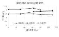
- FIG. 1 is a graph showing the change over time in the TOC value of the treated water of Example 1 and Comparative Examples 3 to 4 treated by the primary pure water system.
- An ultrapure water production apparatus includes a pretreatment system, a primary pure water system, and a subsystem, and the primary pure water system includes a high-pressure reverse osmosis membrane separation device,
- the ultrapure water production apparatus includes a deaeration device, an ultraviolet oxidation device, and an ion exchange device in this order.
- high purity ultrapure water that sufficiently satisfies the required water quality can be produced with a reduced footprint, and the equipment cost (initial cost) and the operation cost It can be manufactured at low cost while suppressing (running cost).
- the primary pure water system provided in the ultrapure water production apparatus includes a high-pressure reverse osmosis membrane separation device, a degassing device, an ultraviolet oxidation device, and an ion exchange device in this order. It is a system with only 4 units.
- the primary pure water system removes ions and organic components from treated water that has been treated with raw water (industrial water, tap water, well water, used ultrapure water discharged from electronic device manufacturing processes, etc.) by the pretreatment system. I do.
- the quality of ultrapure water produced by the ultrapure water production apparatus according to the embodiment of the present invention is described above, for example, although the primary pure water system has only 4 units (A).
- the water quality is equivalent to or better than the water quality. Therefore, the ultrapure water produced by the ultrapure water production apparatus according to the embodiment of the present invention is high purity ultrapure water that sufficiently satisfies the required water quality.
- the ultrapure water produced by the ultrapure water production apparatus of the embodiment according to the present invention sufficiently satisfies the required water quality is determined from raw water (industrial water, tap water, well water, electronic device production process).
- the treated water treated by the pretreatment system is treated by the primary pure water system provided in the ultrapure water production apparatus according to the embodiment of the present invention, so that the treated water is treated.
- the water quality (water quality at the outlet of the primary pure water system) has a specific resistance value of 18 M ⁇ cm or more, a TOC (Total Organic Carbon) concentration of 2 ⁇ g / L or less, a boron (B) concentration of 1 ng / L or less, and a silica (SiO 2 ) concentration of 0.1 ⁇ g / L. Judgment can be made based on the following. Therefore, if the quality of the water to be treated treated by the primary pure water system provided in the ultrapure water production apparatus according to the embodiment of the present invention shows the above values, it is finally treated by the subsystem described later. The ultrapure water thus obtained becomes high purity ultrapure water that sufficiently satisfies the required water quality.
- the high-pressure reverse osmosis membrane separation apparatus removes salts and organic substances.
- the high-pressure type reverse osmosis membrane separation device is a reverse osmosis membrane separation device conventionally used for seawater desalination, and a low pressure used in a primary pure water system provided in a conventional ultrapure water production device.
- the skin layer on the membrane surface is denser than the type or ultra-low pressure type reverse osmosis membrane.
- the high-pressure type reverse osmosis membrane has a lower amount of permeated water per unit operating pressure than the low-pressure type or ultra-low pressure type reverse osmosis membrane, it has weak electrolyte components such as boron, silica, and non-charged organic substances and non-charged components. High removal rate.
- the high-pressure reverse osmosis membrane separation apparatus has a low amount of permeated water per unit operating pressure, and 0.6 to 1.3 m 3 / m 2 / day under conditions of an effective pressure of the membrane surface of 2.0 MPa and 25 ° C.
- the pure water permeation flux may have a NaCl removal rate of 99.5% or more.
- the values of the permeation flux and the NaCl removal rate are It is not limited.
- the effective pressure on the membrane surface is an effective pressure acting on the membrane obtained by subtracting the osmotic pressure difference and the secondary pressure from the average operating pressure, and the NaCl removal rate is 25 ° C. with respect to an aqueous NaCl solution having an NaCl concentration of 32000 mg / L.
- the shape of the high-pressure reverse osmosis membrane may be any shape as long as the object of the present invention is achieved and the effect is exerted, and examples thereof include a spiral shape, a hollow fiber shape, and a flat membrane shape.
- the reason why the high pressure type reverse osmosis membrane separation device is provided is as follows. That is, since the high-pressure type reverse osmosis membrane separation device has a high degree of cross-linking of the polyamide layer for desalting or removing organic substances, as shown in Table 1 below, the ultra-low pressure type or low pressure type conventionally used in the art is used. Compared to a reverse osmosis membrane (RO membrane), the salt removal rate and organic matter removal rate are much higher.
- RO membrane reverse osmosis membrane
- this membrane high pressure type reverse osmosis membrane
- RO membrane ultra-low pressure
- Type or low-pressure type reverse osmosis membrane in particular, the treated water quality equivalent to the two-stage treatment can be obtained.
- the deaerator in the embodiment of the present invention removes IC (inorganic carbon) and dissolved oxygen.
- the reason why the degassing device (degassing device) is provided after the high pressure reverse osmosis membrane separation device treatment is as follows. That is, when a degassing device is installed in the front stage of the high-pressure type reverse osmosis membrane separation device, the degassing membrane or packing material provided in the degassing device due to turbidity in the raw water or Al, SiO 2, etc. (Vacuum degassing, etc.) may become dirty and the degassing efficiency may be reduced. Since the above turbidity or Al, SiO 2, etc. can be removed with a high pressure reverse osmosis membrane, after treatment with a high pressure type reverse osmosis membrane separation device, water to be treated is passed through a deaeration device to remove water. Prevents a decrease in efficiency.
- the deaerator is installed in front of the ion exchanger and UV oxidizer.
- the IC (inorganic carbon) component that can be removed by the degasser is a radical scavenger for the UV oxidizer, while ion exchange An anion load is applied to the apparatus.
- the dissolved oxygen becomes a radical scavenger for the ultraviolet oxidizer, similar to the above IC (inorganic carbon) component,
- dissolved oxygen becomes a factor substance that causes resin oxidation deterioration.
- the deaeration device needs to be installed (provided) in front of the ultraviolet oxidation device and the ion exchange device.
- the degassing apparatus may be any degassing apparatus as long as the object of the present invention is achieved and the effects of the present invention are achieved.
- a decarboxylation tower, a membrane degassing apparatus, a vacuum degassing tower, a nitrogen degassing apparatus examples thereof include an apparatus and a catalyst resin deoxygenation apparatus.
- the reason for installing the ultraviolet oxidation device in the subsequent stage of the deaeration device and in the previous stage of the ion exchange device (tower) is as follows. That is, in the ultraviolet oxidation apparatus, an organic substance in water (treated water) is decomposed into CO 2 and an organic acid by the oxidizing power of OH radicals. The CO 2 or organic acid produced by the ultraviolet oxidation device can be removed by a subsequent ion exchange device (column).
- the ultraviolet oxidation apparatus is not particularly limited as long as it emits light having a wavelength of 185 nm and achieves the object of the present invention and exhibits the effects of the present invention.
- an ultraviolet oxidizer composed of synthetic quartz with very few impurities for both the lamp and the outer tube from the viewpoint of organic matter decomposition efficiency.
- the ion exchange apparatus removes salts and removes charged organic substances.
- the ion exchange device is not particularly limited as long as it achieves the object of the present invention and exhibits the effects of the present invention, but the ion exchange device in the embodiment of the present invention is a regenerative ion exchange device. (Tower) or non-regenerative ion exchanger (tower) is preferable.
- a regenerative ion exchange apparatus for example, a) 2 beds in which a cation exchange column filled with a strongly acidic cation exchange resin and an anion exchange column filled with a strongly basic anion exchange resin are connected in series.
- a two-column regenerative ion exchange apparatus a) a strongly acidic cation exchange resin and the strongly basic anion exchange in one tower so that the strongly acidic cation exchange resin and the strongly basic anion exchange resin are in different layers.
- 2 bed 1 tower type regenerative ion exchange device packed with resin c) mixed bed regenerative ion filled uniformly in strongly acidic cation exchange resin and strongly basic anion exchange resin and packed in one tower Examples thereof include a regenerative ion exchange apparatus in which one or more electric regenerative deionization apparatuses are connected in series.
- the pretreatment system included in the ultrapure water production apparatus includes aggregation / filtration, aggregation / pressure flotation (precipitation) / filtration, and membrane separation system (apparatus), but is not limited thereto. It can be used as long as it is generally used for removing suspended substances and colloidal substances.
- the pretreatment system removes suspended substances and colloidal substances in raw water (industrial water, tap water, well water, used ultrapure water discharged from electronic device manufacturing processes, etc.).
- the subsystem provided in the ultrapure water production apparatus includes a low-pressure ultraviolet oxidation apparatus, an ion exchange apparatus, and an ultrafiltration apparatus, but is not limited thereto.
- the low-pressure ultraviolet oxidizer decomposes and removes organic substances by OH radicals that are generated when water having a wavelength of 185 nm irradiated from a low-pressure ultraviolet lamp is absorbed by water.
- An ion exchange device provided in the subsystem removes trace amounts of ions generated from organic acids or piping generated by a low-pressure ultraviolet oxidation device.
- the ultrafiltration device provided at the end of the subsystem removes fine particles discharged from the piping or the ion exchange device.
- An ultrapure water production method treats treated water obtained by treating raw water by a pretreatment system in the order of a primary pure water system and a subsystem, and performs treatment by the primary pure water system.
- the method includes a step of passing water to be treated through a high pressure type reverse osmosis membrane separator, a step of degassing the gas in the water to be treated, and an ultraviolet oxidation device for removing organic matter in the degassed water to be treated.
- high purity ultrapure water sufficiently satisfying the required water quality can be produced with a reduced footprint, and the equipment cost (initial cost) and the operation cost It can be manufactured at low cost while suppressing (running cost).
- the embodiment according to the present invention can also be configured as follows.
- a pretreatment system, a primary pure water system, and a subsystem are provided, and the primary pure water system includes a high-pressure reverse osmosis membrane separation device, a deaeration device, an ultraviolet oxidation device, and an ion exchange device.
- the ultrapure water production equipment equipped with in this order.
- the high-pressure reverse osmosis membrane separation device has a pure water permeation flux of 0.6 to 1.3 m 3 / m 2 / day under a membrane surface effective pressure of 2.0 MPa and 25 ° C. 1]
- the ultrapure water production apparatus according to 1].
- a mixed bed regenerative ion exchange apparatus in which a strongly acidic cation exchange resin and a strongly basic anion exchange resin are uniformly mixed and packed in one tower.
- a step of passing water, a step of degassing the gas in the water to be treated, a step of decomposing organic matter in the degassed water to be treated by an ultraviolet oxidizer, and the organic matter being decomposed A method for producing ultrapure water, comprising a step of treating water to be treated with an ion exchange device.
- Example 1 Industrial water containing electrical conductivity 30 mS / m, TOC 2 mg / L, SiO 2 10 mg / L and B 30 ⁇ g / L, aggregated filtered water under the condition of pH 6 high pressure type reverse osmosis membrane (SWC4Max, membrane surface effective pressure 2.0 MPa, Pure water permeation flux at a temperature of 25 ° C.
- SWC4Max high pressure type reverse osmosis membrane
- Example 1 The raw water used in the above Example 1 was converted into ultra-low pressure reverse osmosis membrane (RO membrane) (ES-20, effective pressure 2.0 MPa, pure water permeation flux 1 m 3 / m 2 / day at 25 ° C .; effective pressure 0.75 MPa, temperature of 25 ° C., NaCl removal rate of 99.7% at NaCl concentration of 500 mg / L, Nitto Denko's two-stage serial water flow (first stage recovery rate 85%, second stage recovery rate 90%) Except that, water was passed under the same treatment conditions as in Example 1.
- RO membrane reverse osmosis membrane
- Example 2 The raw water used in Example 1 above is No. 1 cation tower (resin brand EX-CG, manufactured by Kurita Kogyo Co., Ltd.), deaerator (degassing membrane, X-50, manufactured by Polypore), No.
- Example 3 The raw water used in the above Example 1 was converted into a high-pressure reverse osmosis membrane device (SWC4Max, manufactured by Nitto Denko) (recovery rate 85%), an ultraviolet oxidation device (JPW, manufactured by Nippon Photoscience), a degassing device (degassing membrane).
- SWC4Max high-pressure reverse osmosis membrane device
- JPW ultraviolet oxidation device
- degassing device degassing membrane
- Example 4 The raw water used in the above Example 1 was degassed (degassing membrane, manufactured by X-50 Polypore), high-pressure reverse osmosis membrane device (SWC4Max, manufactured by Nitto Denko) (recovery rate 85%), ultraviolet oxidation device (JPW, manufactured by Nippon Photo Science Co., Ltd.) The same conditions as in Example 1 except that the treatment was performed in the order of DBP (Double-BedPolisher, manufactured by Kurita Kogyo Co., Ltd.) in which the cation exchange resin layer and the anion exchange resin layer were separated in one tower. The water was passed through.
- DBP Double-BedPolisher, manufactured by Kurita Kogyo Co., Ltd.
- Example 1 has a specific resistance and the ultimate water quality of B (boron) and SiO 2 (silica) is equivalent to the water to be treated of Comparative Examples 1 and 2, but the TOC (Total Organic Carbon) was the lowest value.
- FIG. 1 shows the time-dependent change in the TOC value of the treated water of Example 1 and Comparative Examples 3 to 4 treated by the primary pure water system.
- the water to be treated of Comparative Example 3 tended to have a TOC value higher by about 0.5 ⁇ g / L than the water to be treated of Example 1. This indicates that the TOC decomposition efficiency in the ultraviolet oxidation apparatus varies depending on the order of installation (position) of the deaeration apparatus.
- the water to be treated of Comparative Example 4 had a water quality equivalent to the water to be treated of Example 1 at the start of water flow, but the water quality tends to deteriorate with an increase in the number of days. Observed. It is considered that this is because the deaeration device is contaminated with the raw water-derived substance and the deaeration efficiency is lowered, and accordingly, the ultraviolet oxidative decomposition efficiency is lowered.
Abstract
Description
・逆浸透膜(RO膜)分離装置⇒混床式イオン交換装置(塔)(MB)⇒紫外線殺菌装置(UVst)⇒逆浸透膜(RO膜)分離装置⇒紫外線酸化装置(UVox)⇒非再生型イオン交換装置(塔)⇒脱気装置(MDG)、構成ユニット数は7である。
(B)カチオン及びアニオン交換塔を複数段組み合わせた多段イオン交換システム
・陽イオン交換樹脂(H1)装置(塔)⇒脱炭酸塔⇒陰イオン交換樹脂(OH1)装置(塔)⇒陽イオン交換樹脂(H2)装置(塔)⇒陰イオン交換樹脂(OH2)装置(塔)⇒紫外線殺菌装置(UVst)⇒逆浸透膜(RO膜)分離装置⇒脱気装置(MDG)⇒紫外線酸化装置(UVox)⇒非再生型イオン交換装置(塔)、
構成ユニット数は10である。
・陽イオン交換樹脂(H1)装置(塔)⇒脱炭酸塔⇒陰イオン交換樹脂(OH1)装置(塔)⇒紫外線殺菌装置(UVst)⇒逆浸透膜(RO膜)分離装置⇒紫外線酸化装置(UVox)⇒混床式イオン交換装置(塔)(MB)⇒非再生型イオン交換装置(塔)、構成ユニット数は8である。
(C)複数の電気再生型イオン交換装置からなる多段電気再生式イオン交換純水装置(CDI)システム・逆浸透膜(RO膜)分離装置⇒逆浸透膜(RO膜)分離装置⇒脱気装置(MDG)⇒紫外線酸化装置(UVox)⇒多段電気再生式イオン交換純水装置(CDI)⇒多段電気再生式イオン交換純水装置(CDI)、
構成ユニット数は6である。
上記の(A)~(C)の一次純水システムに用いられている逆浸透膜(RO膜)分離装置において、超低圧型逆浸透膜(RO膜)分離装置(標準運転圧:0.75MPa)が使用されるのが一般的である。
高圧型逆浸透膜分離装置とは、膜面有効圧力2.0MPa、25℃の条件において、0.6~1.3m3/m2/dayの純水透過流束を有する逆浸透膜装置であることが好ましい。
イオン交換装置が以下のア)~エ)のいずれか1つの再生型イオン交換装置であることが好ましい。
ア)強酸性カチオン交換樹脂が充填されたカチオン交換塔と、強塩基性アニオン交換樹脂が充填されたアニオン交換塔とを直列に接続した2床2塔式再生型イオン交換装置。
イ)強酸性カチオン交換樹脂と強塩基性アニオン交換樹脂とが別々の異なる層となるように1つの塔内に該強酸性カチオン交換樹脂と該強塩基性アニオン交換樹脂とを充填した2床1塔式再生型イオン交換装置。
ウ)強酸性カチオン交換樹脂と強塩基性アニオン交換樹脂とを均一に混合して1つの塔内に充填した混床型再生式イオン交換装置。
エ)電気再生式脱イオン装置を1段又は複数段直列に接続した再生型イオン交換装置。
本発明に係る実施形態の超純水製造装置は、前処理システムと、一次純水システムと、サブシステムとを備え、一次純水システムが、高圧型逆浸透膜分離装置と、脱気装置と、紫外線酸化装置と、イオン交換装置とをこの順で備える、超純水製造装置である。本実施形態の超純水製造装置によれば、要求水質を充分に満足した高純度の超純水を、フットプリントを軽減させて製造することができ、さらに設備コスト(イニシャルコスト)及び運営コスト(ランニングコスト)を抑えながら安価に製造することができる。
本発明に係る実施形態の超純水製造装置に備えられる一次純水システムは、高圧型逆浸透膜分離装置と、脱気装置と、紫外線酸化装置と、イオン交換装置とをこの順で備える、僅か4ユニット構成のシステムである。一次純水システムは、原水(工業用水、水道水、井水、電子デバイス製造工程から排出される使用済みの超純水等)を前処理システムによって処理した被処理水中のイオンや有機成分の除去を行う。そして、一次純水システムが僅か4ユニット構成であるにもかかわらず、本発明に係る実施形態の超純水製造装置によって製造された超純水の水質は、例えば、上記で述べた(A)~(C)の一次純水システムのように逆浸透膜分離装置及び/又はイオン交換装置(塔)を複数段に設置した一次純水システムを備える超純水製造装置によって製造された超純水の水質に対して同等以上の水質を示す。したがって、本発明に係る実施形態の超純水製造装置によって製造された超純水は、要求水質を充分に満足した高純度の超純水である。

本発明に係る実施形態の超純水製造装置に備えられる前処理システムは、凝集・ろ過、凝集・加圧浮上(沈殿)・ろ過、膜分離システム(装置)を備えるが、これに限定されるものではなく、懸濁物質やコロイダル物質の除去に一般に使用されるものであれば使用することが可能である。前処理システムは原水(工業用水、水道水、井水、電子デバイス製造工程から排出される使用済みの超純水等)中の懸濁物質やコロイダル物質の除去を行う。
本発明に係る実施形態の超純水製造装置に備えられるサブシステムは、低圧紫外線酸化装置、イオン交換装置及び限外ろ過装置を備えるが、これらに限定されるものでない。サブシステムでは、超純水の純度を一層高める。低圧紫外線酸化装置は低圧紫外線ランプより照射される185nm波長光が水に吸収されることにより生じるOHラジカルにより有機物の分解除去を行う。サブシステム内に備えられるイオン交換装置は低圧紫外線酸化装置により生成される有機酸あるいは配管等から発生する微量イオンの除去を行う。サブシステムの末端に備えられる限外ろ過装置は配管あるいはイオン交換装置から排出される微粒子の除去を行う。
本発明に係る実施形態の超純水製造方法は、原水を前処理システムによって処理した被処理水を一次純水システム及びサブシステムの順によって処理し、一次純水システムによる処理方法が、高圧型逆浸透膜分離装置に被処理水を通水する工程と、通水された被処理水中のガスを脱気する工程と、脱気された被処理水中の有機物を紫外線酸化装置によって分解する工程と、有機物が分解された被処理水を、イオン交換装置によって処理する工程とを含む、超純水製造方法である。本実施形態の超純水製造方法によれば、要求水質を充分に満足した高純度の超純水を、フットプリントを軽減させて製造することができ、さらに設備コスト(イニシャルコスト)及び運営コスト(ランニングコスト)を抑えながら安価に製造することができる。
[1]前処理システムと、一次純水システムと、サブシステムとを備え、その一次純水システムが、高圧型逆浸透膜分離装置と、脱気装置と、紫外線酸化装置と、イオン交換装置とをこの順で備える、超純水製造装置。
[2]その高圧型逆浸透膜分離装置が、膜面有効圧力2.0MPa、25℃条件下において0.6~1.3m3/m2/dayの純水透過流束を有する、上記[1]に記載の超純水製造装置。
[3]そのイオン交換装置が、以下のア)~エ)のいずれか1つの再生型イオン交換装置を有する、上記[1]又は[2]に記載の超純水製造装置。
ア)強酸性カチオン交換樹脂が充填されたカチオン交換塔と、強塩基性アニオン交換樹脂が充填されたアニオン交換塔とを直列に接続した2床2塔式再生型イオン交換装置。
イ)強酸性カチオン交換樹脂と強塩基性アニオン交換樹脂とが別々の異なる層となるように1つの塔内にその強酸性カチオン交換樹脂とその強塩基性アニオン交換樹脂とを充填した2床1塔式再生型イオン交換装置。
ウ)強酸性カチオン交換樹脂と強塩基性アニオン交換樹脂とを均一に混合して1つの塔内に充填した混床型再生式イオン交換装置。
エ)電気再生式脱イオン装置を1段又は複数段直列に接続した再生型イオン交換装置。
[4]原水を前処理システムによって処理した被処理水を一次純水システム及びサブシステムの順によって処理し、その一次純水システムによる処理方法が、高圧型逆浸透膜分離装置に該被処理水を通水する工程と、その通水された被処理水中のガスを脱気する工程と、その脱気された被処理水中の有機物を紫外線酸化装置によって分解する工程と、その有機物が分解された被処理水を、イオン交換装置によって処理する工程とを含む、超純水製造方法。
電気伝導率30mS/m, TOC2mg/L、SiO210mg/L及びB30μg/Lを含む工業用水、凝集ろ過水をpH6の条件にて高圧型逆浸透膜(SWC4Max、膜面有効圧力2.0MPa、温度25℃における純水透過流束0.78m3/m2/day;有効圧2.0MPa、温度25℃、NaCl濃度32000mg/LにおけるNaCl除去率99.8%、日東電工製)(回収率85%)に通水した後、脱気装置(脱気膜、X-50ポリポア社製)、紫外線酸化装置(JPW、日本フォトサイエンス製)、次いで1塔内でカチオン交換樹脂層、及びアニオン交換樹脂層を分離したDBP(Double-BedPolisher、栗田工業製)に通水した。
上記の実施例1で用いた原水を超低圧型逆浸透膜(RO膜)(ES-20、有効圧2.0MPa、温度25℃における純水透過流束1m3/m2/day;有効圧0.75MPa、温度25℃、NaCl濃度500mg/LにおけるNaCl除去率99.7%、日東電工製)の2段直列で通水(1段目回収率85%、2段目回収率90%)したこと以外は実施例1と同様の処理条件で通水した。
上記の実施例1で用いた原水を、No.1カチオン塔(樹脂銘柄EX-CG、栗田工業製)、脱気装置(脱気膜、X-50、ポリポア社製)、No.1アニオン塔(樹脂銘柄EX-AG、栗田工業製)、超低圧型逆浸透膜(RO膜)(ES-20、日東電工製)(回収
率90%)、紫外線酸化装置(JPW、日本フォトサイエンス製)、混床式イオン交換装置(MB)(樹脂銘柄EX-MG、栗田工業製)、非再生型イオン交換装置(樹脂銘柄EX-MG、栗田工業製)の順に通水した。脱気装置及び紫外線酸化装置の台数は実施例1と同台数に設置した。
上記の実施例1で用いた原水を、高圧型逆浸透膜装置(SWC4Max、日東電工製)(回収率85%)、紫外線酸化装置(JPW、日本フォトサイエンス製)、脱気装置(脱気膜、X-50ポリポア社製)、1塔内でカチオン交換樹脂層及びアニオン交換樹脂層を分離したDBP(Double-BedPolisher、栗田工業製)の順として処理した以外は実施例1と同条件にて通水した。
上記の実施例1で用いた原水を、脱気装置(脱気膜、X-50ポリポア社製)、高圧型逆浸透膜装置(SWC4Max、日東電工製)(回収率85%)、紫外線酸化装置(JPW、日本フォトサイエンス製)、1塔内でカチオン交換樹脂層及びアニオン交換樹脂層を分離したDBP(Double-BedPolisher、栗田工業株式会社製)の順として処理した以外は実施例1と同条件にて通水した。

Claims (4)
- 前処理システムと、一次純水システムと、サブシステムとを備え、
該一次純水システムが、高圧型逆浸透膜分離装置と、脱気装置と、紫外線酸化装置と、イオン交換装置とをこの順で備える、
超純水製造装置。 - 前記高圧型逆浸透膜分離装置が、膜面有効圧力2.0MPa、25℃条件下において0.6~1.3m3/m2/dayの純水透過流束を有する、請求項1に記載の超純水製造装置。
- 前記イオン交換装置が、以下のア)~エ)のいずれか1つの再生型イオン交換装置を有する、請求項1又は2に記載の超純水製造装置。
ア)強酸性カチオン交換樹脂が充填されたカチオン交換塔と、強塩基性アニオン交換樹脂が充填されたアニオン交換塔とを直列に接続した2床2塔式再生型イオン交換装置。
イ)強酸性カチオン交換樹脂と強塩基性アニオン交換樹脂とが別々の異なる層となるように1つの塔内に該強酸性カチオン交換樹脂と該強塩基性アニオン交換樹脂とを充填した2床1塔式再生型イオン交換装置。
ウ)強酸性カチオン交換樹脂と強塩基性アニオン交換樹脂とを均一に混合して1つの塔内に充填した混床型再生式イオン交換装置。
エ)電気再生式脱イオン装置を1段又は複数段直列に接続した再生型イオン交換装置。 - 原水を前処理システムによって処理した被処理水を一次純水システム及びサブシステムの順によって処理し、
該一次純水システムによる処理方法が、高圧型逆浸透膜分離装置に該被処理水を通水する工程と、該通水された被処理水中のガスを脱気する工程と、該脱気された被処理水中の有機物を紫外線酸化装置によって分解する工程と、該有機物が分解された被処理水を、イオン交換装置によって処理する工程とを含む、
超純水製造方法。
Priority Applications (3)
| Application Number | Priority Date | Filing Date | Title |
|---|---|---|---|
| US15/536,510 US10526226B2 (en) | 2014-12-19 | 2015-12-18 | Ultrapure water production apparatus and ultrapure water production method |
| KR1020177016234A KR102309232B1 (ko) | 2014-12-19 | 2015-12-18 | 초순수 제조 장치 및 초순수 제조 방법 |
| CN201580067856.3A CN107001075A (zh) | 2014-12-19 | 2015-12-18 | 超纯水制造装置以及超纯水制造方法 |
Applications Claiming Priority (2)
| Application Number | Priority Date | Filing Date | Title |
|---|---|---|---|
| JP2014256939A JP6228531B2 (ja) | 2014-12-19 | 2014-12-19 | 超純水製造装置及び超純水製造方法 |
| JP2014-256939 | 2014-12-19 |
Publications (1)
| Publication Number | Publication Date |
|---|---|
| WO2016098891A1 true WO2016098891A1 (ja) | 2016-06-23 |
Family
ID=56126770
Family Applications (1)
| Application Number | Title | Priority Date | Filing Date |
|---|---|---|---|
| PCT/JP2015/085526 WO2016098891A1 (ja) | 2014-12-19 | 2015-12-18 | 超純水製造装置及び超純水製造方法 |
Country Status (6)
| Country | Link |
|---|---|
| US (1) | US10526226B2 (ja) |
| JP (1) | JP6228531B2 (ja) |
| KR (1) | KR102309232B1 (ja) |
| CN (1) | CN107001075A (ja) |
| TW (1) | TWI648093B (ja) |
| WO (1) | WO2016098891A1 (ja) |
Families Citing this family (16)
| Publication number | Priority date | Publication date | Assignee | Title |
|---|---|---|---|---|
| JP6752692B2 (ja) * | 2016-11-18 | 2020-09-09 | オルガノ株式会社 | 水処理方法および装置 |
| JP6752693B2 (ja) * | 2016-11-18 | 2020-09-09 | オルガノ株式会社 | 水処理方法および装置 |
| JP6907514B2 (ja) * | 2016-11-28 | 2021-07-21 | 栗田工業株式会社 | 超純水製造システム及び超純水製造方法 |
| JP6350706B1 (ja) * | 2017-03-30 | 2018-07-04 | 栗田工業株式会社 | 水質調整水製造装置 |
| JP6299912B1 (ja) * | 2017-03-30 | 2018-03-28 | 栗田工業株式会社 | pH及び酸化還元電位を制御可能な希釈薬液の製造装置 |
| JP6299913B1 (ja) * | 2017-03-30 | 2018-03-28 | 栗田工業株式会社 | pH・酸化還元電位調整水の製造装置 |
| JP6978353B2 (ja) * | 2018-03-13 | 2021-12-08 | オルガノ株式会社 | 水処理管理装置及び水質監視方法 |
| US11897790B2 (en) | 2018-05-17 | 2024-02-13 | Organo Corporation | Method for producing ultrapure water, ultrapure water production system, and ion exchanger-filled module |
| JP7454330B2 (ja) * | 2018-06-20 | 2024-03-22 | オルガノ株式会社 | 被処理水中のホウ素除去方法、ホウ素除去システム、超純水製造システム及びホウ素濃度の測定方法 |
| CN108862756A (zh) * | 2018-07-31 | 2018-11-23 | 江西鹏凯环保工程设备有限公司 | 一种超纯水制备装置及其超纯水制备方法 |
| JP2020142178A (ja) * | 2019-03-05 | 2020-09-10 | 栗田工業株式会社 | 超純水製造装置及び超純水製造装置の運転方法 |
| JP7289206B2 (ja) * | 2019-03-13 | 2023-06-09 | オルガノ株式会社 | ホウ素除去装置及びホウ素除去方法、並びに、純水製造装置及び純水の製造方法 |
| JP6900975B2 (ja) * | 2019-06-12 | 2021-07-14 | 栗田工業株式会社 | pH調整水製造装置 |
| JP7183208B2 (ja) * | 2020-02-14 | 2022-12-05 | 栗田工業株式会社 | 超純水製造装置及び超純水製造方法 |
| JP2022053969A (ja) * | 2020-09-25 | 2022-04-06 | オルガノ株式会社 | 純水製造装置及び純水製造方法 |
| CN112321099B (zh) * | 2020-12-02 | 2024-02-23 | 中国电子系统工程第二建设有限公司 | 一种处理再生水中尿素的方法 |
Citations (4)
| Publication number | Priority date | Publication date | Assignee | Title |
|---|---|---|---|---|
| JPH1085740A (ja) * | 1996-09-11 | 1998-04-07 | Japan Organo Co Ltd | 超純水製造装置 |
| JPH10180254A (ja) * | 1996-12-24 | 1998-07-07 | Nomura Micro Sci Co Ltd | 純水の製造方法及び製造装置 |
| JP2012245439A (ja) * | 2011-05-25 | 2012-12-13 | Kurita Water Ind Ltd | 超純水製造装置 |
| JP2015020131A (ja) * | 2013-07-22 | 2015-02-02 | 栗田工業株式会社 | ホウ素含有水の処理方法及び装置 |
Family Cites Families (18)
| Publication number | Priority date | Publication date | Assignee | Title |
|---|---|---|---|---|
| JPH0771669B2 (ja) * | 1990-08-29 | 1995-08-02 | 日本錬水株式会社 | 超純水の製造法 |
| JP2940651B2 (ja) * | 1992-03-11 | 1999-08-25 | オルガノ株式会社 | 純水製造装置 |
| JP3539992B2 (ja) | 1993-09-07 | 2004-07-07 | 野村マイクロ・サイエンス株式会社 | 超純水製造装置 |
| JP3262949B2 (ja) | 1993-09-13 | 2002-03-04 | 野村マイクロ・サイエンス株式会社 | 低濃度有機性廃水の処理装置 |
| JP3200301B2 (ja) | 1994-07-22 | 2001-08-20 | オルガノ株式会社 | 純水又は超純水の製造方法及び製造装置 |
| US5954965A (en) * | 1996-03-29 | 1999-09-21 | Mitsubishi Chemical Corporation | Process for producing pure water |
| JPH10137750A (ja) * | 1996-11-14 | 1998-05-26 | Mitsubishi Chem Corp | 純水製造装置の殺菌方法 |
| JP3632343B2 (ja) * | 1996-12-26 | 2005-03-23 | オルガノ株式会社 | 純水製造方法及びイオン交換塔 |
| JP3826690B2 (ja) * | 1999-08-11 | 2006-09-27 | 栗田工業株式会社 | 電気脱イオン装置及び純水製造装置 |
| JP2003266097A (ja) * | 2002-03-13 | 2003-09-24 | Kurita Water Ind Ltd | 超純水製造装置 |
| CN1176032C (zh) * | 2002-09-24 | 2004-11-17 | 天津大学 | 一种电子级水的集成膜过程生产方法 |
| WO2004071968A1 (ja) * | 2003-02-14 | 2004-08-26 | Kurita Water Industries Ltd. | 電気脱イオン装置及びその運転方法 |
| JP3853776B2 (ja) | 2003-10-06 | 2006-12-06 | 野村マイクロ・サイエンス株式会社 | 超純水製造装置 |
| DE102007031113A1 (de) * | 2007-06-29 | 2009-01-02 | Christ Water Technology Ag | Aufbereitung von Wasser mit Hypobromitlösung |
| JP5257619B2 (ja) * | 2009-08-26 | 2013-08-07 | 栗田工業株式会社 | 純水製造装置 |
| CN201634548U (zh) * | 2010-03-04 | 2010-11-17 | 安纳社环保工程(苏州)有限公司 | 半导体行业研磨废水回用为超纯水的处理系统 |
| JP5849419B2 (ja) * | 2011-03-29 | 2016-01-27 | 栗田工業株式会社 | 純水製造装置 |
| JP6082192B2 (ja) | 2012-06-11 | 2017-02-15 | 野村マイクロ・サイエンス株式会社 | 純水製造装置 |
-
2014
- 2014-12-19 JP JP2014256939A patent/JP6228531B2/ja active Active
-
2015
- 2015-12-18 KR KR1020177016234A patent/KR102309232B1/ko active IP Right Grant
- 2015-12-18 WO PCT/JP2015/085526 patent/WO2016098891A1/ja active Application Filing
- 2015-12-18 CN CN201580067856.3A patent/CN107001075A/zh active Pending
- 2015-12-18 TW TW104142774A patent/TWI648093B/zh active
- 2015-12-18 US US15/536,510 patent/US10526226B2/en active Active
Patent Citations (4)
| Publication number | Priority date | Publication date | Assignee | Title |
|---|---|---|---|---|
| JPH1085740A (ja) * | 1996-09-11 | 1998-04-07 | Japan Organo Co Ltd | 超純水製造装置 |
| JPH10180254A (ja) * | 1996-12-24 | 1998-07-07 | Nomura Micro Sci Co Ltd | 純水の製造方法及び製造装置 |
| JP2012245439A (ja) * | 2011-05-25 | 2012-12-13 | Kurita Water Ind Ltd | 超純水製造装置 |
| JP2015020131A (ja) * | 2013-07-22 | 2015-02-02 | 栗田工業株式会社 | ホウ素含有水の処理方法及び装置 |
Also Published As
| Publication number | Publication date |
|---|---|
| JP2016117001A (ja) | 2016-06-30 |
| JP6228531B2 (ja) | 2017-11-08 |
| TW201630653A (zh) | 2016-09-01 |
| CN107001075A (zh) | 2017-08-01 |
| US20170327396A1 (en) | 2017-11-16 |
| TWI648093B (zh) | 2019-01-21 |
| KR20170097036A (ko) | 2017-08-25 |
| US10526226B2 (en) | 2020-01-07 |
| KR102309232B1 (ko) | 2021-10-05 |
Similar Documents
| Publication | Publication Date | Title |
|---|---|---|
| JP6228531B2 (ja) | 超純水製造装置及び超純水製造方法 | |
| JP5045099B2 (ja) | 超純水製造装置及び超純水製造装置の運転方法 | |
| JP5733351B2 (ja) | ホウ素含有水の処理方法及び装置 | |
| TWI414486B (zh) | Pure water manufacturing apparatus and pure water manufacturing method | |
| JP5617231B2 (ja) | イオン交換樹脂の精製方法及び精製装置 | |
| JP5834492B2 (ja) | 超純水製造装置 | |
| CN111252971A (zh) | 一种超纯水制造系统及使用该系统的超纯水制造方法 | |
| TWI829879B (zh) | 硼去除裝置與硼去除方法、以及純水製造裝置與純水之製造方法 | |
| JP6228471B2 (ja) | 被処理水の処理装置、純水の製造装置および被処理水の処理方法 | |
| JP2017127875A (ja) | 超純水製造装置及び超純水製造方法 | |
| JP2004000919A (ja) | 脱塩水製造装置 | |
| WO2018096700A1 (ja) | 超純水製造システム及び超純水製造方法 | |
| JP2007307561A (ja) | 高純度水の製造装置および方法 | |
| JP2000015257A (ja) | 高純度水の製造装置および方法 | |
| WO2021215099A1 (ja) | 排水処理方法、超純水製造方法及び排水処理装置 | |
| WO2021161569A1 (ja) | 超純水製造装置及び超純水製造方法 | |
| JP2002355683A (ja) | 超純水製造方法及び超純水製造装置 | |
| CN212269740U (zh) | 一种超纯水制造系统 | |
| WO2022239483A1 (ja) | 超純水製造方法及び装置 | |
| WO2014010075A1 (ja) | 超純水製造装置 | |
| JP6728835B2 (ja) | 純水製造装置の運転方法 | |
| JP6285645B2 (ja) | 排水処理方法及び排水処理装置 | |
| TWI592207B (zh) | Ultrapure water manufacturing equipment | |
| JP2019107631A (ja) | 紫外線酸化処理方法 | |
| JP2017140548A (ja) | 電気脱イオン装置の運転方法 |
Legal Events
| Date | Code | Title | Description |
|---|---|---|---|
| 121 | Ep: the epo has been informed by wipo that ep was designated in this application |
Ref document number: 15870090 Country of ref document: EP Kind code of ref document: A1 |
|
| ENP | Entry into the national phase |
Ref document number: 20177016234 Country of ref document: KR Kind code of ref document: A |
|
| WWE | Wipo information: entry into national phase |
Ref document number: 15536510 Country of ref document: US |
|
| NENP | Non-entry into the national phase |
Ref country code: DE |
|
| 122 | Ep: pct application non-entry in european phase |
Ref document number: 15870090 Country of ref document: EP Kind code of ref document: A1 |