WO2016093361A1 - 圧縮機 - Google Patents
圧縮機 Download PDFInfo
- Publication number
- WO2016093361A1 WO2016093361A1 PCT/JP2015/084859 JP2015084859W WO2016093361A1 WO 2016093361 A1 WO2016093361 A1 WO 2016093361A1 JP 2015084859 W JP2015084859 W JP 2015084859W WO 2016093361 A1 WO2016093361 A1 WO 2016093361A1
- Authority
- WO
- WIPO (PCT)
- Prior art keywords
- oil
- path
- drive shaft
- shaft
- inflow path
- Prior art date
Links
Images


Classifications
-
- F—MECHANICAL ENGINEERING; LIGHTING; HEATING; WEAPONS; BLASTING
- F04—POSITIVE - DISPLACEMENT MACHINES FOR LIQUIDS; PUMPS FOR LIQUIDS OR ELASTIC FLUIDS
- F04C—ROTARY-PISTON, OR OSCILLATING-PISTON, POSITIVE-DISPLACEMENT MACHINES FOR LIQUIDS; ROTARY-PISTON, OR OSCILLATING-PISTON, POSITIVE-DISPLACEMENT PUMPS
- F04C29/00—Component parts, details or accessories of pumps or pumping installations, not provided for in groups F04C18/00 - F04C28/00
- F04C29/02—Lubrication; Lubricant separation
- F04C29/021—Control systems for the circulation of the lubricant
-
- F—MECHANICAL ENGINEERING; LIGHTING; HEATING; WEAPONS; BLASTING
- F04—POSITIVE - DISPLACEMENT MACHINES FOR LIQUIDS; PUMPS FOR LIQUIDS OR ELASTIC FLUIDS
- F04C—ROTARY-PISTON, OR OSCILLATING-PISTON, POSITIVE-DISPLACEMENT MACHINES FOR LIQUIDS; ROTARY-PISTON, OR OSCILLATING-PISTON, POSITIVE-DISPLACEMENT PUMPS
- F04C27/00—Sealing arrangements in rotary-piston pumps specially adapted for elastic fluids
- F04C27/008—Sealing arrangements in rotary-piston pumps specially adapted for elastic fluids for other than working fluid, i.e. the sealing arrangements are not between working chambers of the machine
- F04C27/009—Shaft sealings specially adapted for pumps
-
- F—MECHANICAL ENGINEERING; LIGHTING; HEATING; WEAPONS; BLASTING
- F04—POSITIVE - DISPLACEMENT MACHINES FOR LIQUIDS; PUMPS FOR LIQUIDS OR ELASTIC FLUIDS
- F04B—POSITIVE-DISPLACEMENT MACHINES FOR LIQUIDS; PUMPS
- F04B39/00—Component parts, details, or accessories, of pumps or pumping systems specially adapted for elastic fluids, not otherwise provided for in, or of interest apart from, groups F04B25/00 - F04B37/00
- F04B39/02—Lubrication
- F04B39/0223—Lubrication characterised by the compressor type
- F04B39/023—Hermetic compressors
- F04B39/0261—Hermetic compressors with an auxiliary oil pump
-
- F—MECHANICAL ENGINEERING; LIGHTING; HEATING; WEAPONS; BLASTING
- F04—POSITIVE - DISPLACEMENT MACHINES FOR LIQUIDS; PUMPS FOR LIQUIDS OR ELASTIC FLUIDS
- F04C—ROTARY-PISTON, OR OSCILLATING-PISTON, POSITIVE-DISPLACEMENT MACHINES FOR LIQUIDS; ROTARY-PISTON, OR OSCILLATING-PISTON, POSITIVE-DISPLACEMENT PUMPS
- F04C18/00—Rotary-piston pumps specially adapted for elastic fluids
- F04C18/02—Rotary-piston pumps specially adapted for elastic fluids of arcuate-engagement type, i.e. with circular translatory movement of co-operating members, each member having the same number of teeth or tooth-equivalents
- F04C18/0207—Rotary-piston pumps specially adapted for elastic fluids of arcuate-engagement type, i.e. with circular translatory movement of co-operating members, each member having the same number of teeth or tooth-equivalents both members having co-operating elements in spiral form
- F04C18/0215—Rotary-piston pumps specially adapted for elastic fluids of arcuate-engagement type, i.e. with circular translatory movement of co-operating members, each member having the same number of teeth or tooth-equivalents both members having co-operating elements in spiral form where only one member is moving
-
- F—MECHANICAL ENGINEERING; LIGHTING; HEATING; WEAPONS; BLASTING
- F04—POSITIVE - DISPLACEMENT MACHINES FOR LIQUIDS; PUMPS FOR LIQUIDS OR ELASTIC FLUIDS
- F04C—ROTARY-PISTON, OR OSCILLATING-PISTON, POSITIVE-DISPLACEMENT MACHINES FOR LIQUIDS; ROTARY-PISTON, OR OSCILLATING-PISTON, POSITIVE-DISPLACEMENT PUMPS
- F04C29/00—Component parts, details or accessories of pumps or pumping installations, not provided for in groups F04C18/00 - F04C28/00
- F04C29/0042—Driving elements, brakes, couplings, transmissions specially adapted for pumps
- F04C29/005—Means for transmitting movement from the prime mover to driven parts of the pump, e.g. clutches, couplings, transmissions
- F04C29/0057—Means for transmitting movement from the prime mover to driven parts of the pump, e.g. clutches, couplings, transmissions for eccentric movement
-
- F—MECHANICAL ENGINEERING; LIGHTING; HEATING; WEAPONS; BLASTING
- F04—POSITIVE - DISPLACEMENT MACHINES FOR LIQUIDS; PUMPS FOR LIQUIDS OR ELASTIC FLUIDS
- F04C—ROTARY-PISTON, OR OSCILLATING-PISTON, POSITIVE-DISPLACEMENT MACHINES FOR LIQUIDS; ROTARY-PISTON, OR OSCILLATING-PISTON, POSITIVE-DISPLACEMENT PUMPS
- F04C29/00—Component parts, details or accessories of pumps or pumping installations, not provided for in groups F04C18/00 - F04C28/00
- F04C29/0042—Driving elements, brakes, couplings, transmissions specially adapted for pumps
- F04C29/0085—Prime movers
-
- F—MECHANICAL ENGINEERING; LIGHTING; HEATING; WEAPONS; BLASTING
- F04—POSITIVE - DISPLACEMENT MACHINES FOR LIQUIDS; PUMPS FOR LIQUIDS OR ELASTIC FLUIDS
- F04C—ROTARY-PISTON, OR OSCILLATING-PISTON, POSITIVE-DISPLACEMENT MACHINES FOR LIQUIDS; ROTARY-PISTON, OR OSCILLATING-PISTON, POSITIVE-DISPLACEMENT PUMPS
- F04C29/00—Component parts, details or accessories of pumps or pumping installations, not provided for in groups F04C18/00 - F04C28/00
- F04C29/02—Lubrication; Lubricant separation
- F04C29/023—Lubricant distribution through a hollow driving shaft
-
- F—MECHANICAL ENGINEERING; LIGHTING; HEATING; WEAPONS; BLASTING
- F04—POSITIVE - DISPLACEMENT MACHINES FOR LIQUIDS; PUMPS FOR LIQUIDS OR ELASTIC FLUIDS
- F04C—ROTARY-PISTON, OR OSCILLATING-PISTON, POSITIVE-DISPLACEMENT MACHINES FOR LIQUIDS; ROTARY-PISTON, OR OSCILLATING-PISTON, POSITIVE-DISPLACEMENT PUMPS
- F04C29/00—Component parts, details or accessories of pumps or pumping installations, not provided for in groups F04C18/00 - F04C28/00
- F04C29/02—Lubrication; Lubricant separation
- F04C29/025—Lubrication; Lubricant separation using a lubricant pump
-
- F—MECHANICAL ENGINEERING; LIGHTING; HEATING; WEAPONS; BLASTING
- F04—POSITIVE - DISPLACEMENT MACHINES FOR LIQUIDS; PUMPS FOR LIQUIDS OR ELASTIC FLUIDS
- F04C—ROTARY-PISTON, OR OSCILLATING-PISTON, POSITIVE-DISPLACEMENT MACHINES FOR LIQUIDS; ROTARY-PISTON, OR OSCILLATING-PISTON, POSITIVE-DISPLACEMENT PUMPS
- F04C11/00—Combinations of two or more machines or pumps, each being of rotary-piston or oscillating-piston type; Pumping installations
- F04C11/001—Combinations of two or more machines or pumps, each being of rotary-piston or oscillating-piston type; Pumping installations of similar working principle
- F04C11/003—Combinations of two or more machines or pumps, each being of rotary-piston or oscillating-piston type; Pumping installations of similar working principle having complementary function
-
- F—MECHANICAL ENGINEERING; LIGHTING; HEATING; WEAPONS; BLASTING
- F04—POSITIVE - DISPLACEMENT MACHINES FOR LIQUIDS; PUMPS FOR LIQUIDS OR ELASTIC FLUIDS
- F04C—ROTARY-PISTON, OR OSCILLATING-PISTON, POSITIVE-DISPLACEMENT MACHINES FOR LIQUIDS; ROTARY-PISTON, OR OSCILLATING-PISTON, POSITIVE-DISPLACEMENT PUMPS
- F04C2240/00—Components
- F04C2240/60—Shafts
- F04C2240/603—Shafts with internal channels for fluid distribution, e.g. hollow shaft
-
- F—MECHANICAL ENGINEERING; LIGHTING; HEATING; WEAPONS; BLASTING
- F04—POSITIVE - DISPLACEMENT MACHINES FOR LIQUIDS; PUMPS FOR LIQUIDS OR ELASTIC FLUIDS
- F04C—ROTARY-PISTON, OR OSCILLATING-PISTON, POSITIVE-DISPLACEMENT MACHINES FOR LIQUIDS; ROTARY-PISTON, OR OSCILLATING-PISTON, POSITIVE-DISPLACEMENT PUMPS
- F04C2240/00—Components
- F04C2240/80—Other components
- F04C2240/807—Balance weight, counterweight
-
- F—MECHANICAL ENGINEERING; LIGHTING; HEATING; WEAPONS; BLASTING
- F04—POSITIVE - DISPLACEMENT MACHINES FOR LIQUIDS; PUMPS FOR LIQUIDS OR ELASTIC FLUIDS
- F04C—ROTARY-PISTON, OR OSCILLATING-PISTON, POSITIVE-DISPLACEMENT MACHINES FOR LIQUIDS; ROTARY-PISTON, OR OSCILLATING-PISTON, POSITIVE-DISPLACEMENT PUMPS
- F04C23/00—Combinations of two or more pumps, each being of rotary-piston or oscillating-piston type, specially adapted for elastic fluids; Pumping installations specially adapted for elastic fluids; Multi-stage pumps specially adapted for elastic fluids
- F04C23/008—Hermetic pumps
Definitions
- the present invention relates to a compressor. More specifically, the present invention relates to a compressor in which an oil discharge path for discharging oil accumulated in a crank chamber is formed in a drive shaft.
- Patent Document 1 Japanese Patent Laid-Open No. 2013-177877
- the oil in the oil reservoir space at the bottom of the casing is placed inside the eccentric portion of the drive shaft.
- Patent Document 1 Japanese Patent Laid-Open No. 2013-177877
- the oil drainage path extends in the drive shaft in the axial direction and extends from the main path in a direction crossing the axial direction, and is opened to the crank chamber. Including an inflow path.
- Patent Document 1 Japanese Patent Laid-Open No. 2013-177877
- An object of the present invention is a compressor in which an oil discharge path for discharging oil in a crank chamber is formed in a drive shaft, where oil accumulates in the crank chamber and the pressure in the crank chamber increases excessively. It is to provide a compressor that can be prevented.
- the compressor according to the first aspect of the present invention includes a casing, an electric motor, a drive shaft, a compression mechanism, an oil supply path, an oil discharge path, an oil supply pump, and an oil discharge pump.
- An oil reservoir space is formed at the bottom of the casing.
- the electric motor is accommodated in the casing.
- the drive shaft extends in the vertical direction and is connected to the electric motor.
- the compression mechanism is accommodated in the casing and has a movable part and an upper housing.
- the movable part is connected to a drive shaft and driven by an electric motor.
- the upper housing forms a crank chamber in which a connecting portion between the eccentric portion of the drive shaft and the movable portion is accommodated.
- the upper housing has an upper bearing portion that supports the drive shaft below the crank chamber.
- the oil supply path conveys oil in the oil reservoir space to the crank chamber.
- the oil supply path is formed inside the drive shaft.
- the oil drainage path includes an oil drainage main path and a first inflow path.
- the oil drain main path extends in the axial direction inside the drive shaft.
- the first inflow path communicates the oil drain main path and the crank chamber.
- the oil supply pump supplies oil in the oil reservoir space to the oil supply path.
- the oil discharge pump discharges the oil in the crank chamber to the oil reservoir space via the oil discharge path.
- An oil recovery space is formed in the lower part of the upper housing below the crank chamber.
- the oil drainage path further includes a second inflow path that connects the oil drainage main path and the oil recovery space.
- the oil discharge path in addition to the first inflow path communicating with the crank chamber, is located in the oil recovery space formed below the crank chamber and in the lower portion of the upper housing. It has the 2nd inflow path which connects. Therefore, it is possible to increase the amount of oil flowing into the oil drain main path, and it is possible to prevent oil from accumulating in the crank chamber and excessively increasing the pressure.
- the compressor according to the second aspect of the present invention is the compressor according to the first aspect, and the oil recovery space is formed below the upper bearing portion.
- the compressor according to the third aspect of the present invention is the compressor according to the first aspect or the second aspect, and the upper housing further includes an upper shaft seal portion disposed below the oil recovery space.
- the compressor further includes an upper shaft seal ring disposed in the upper shaft seal portion.
- a compressor according to a fourth aspect of the present invention is the compressor according to the third aspect, further comprising a lower housing and a lower shaft seal ring.
- the lower housing has a lower bearing portion and a lower shaft seal portion.
- the lower bearing portion pivotally supports the drive shaft.
- the lower shaft seal portion is disposed above the lower bearing portion.
- the lower shaft seal ring is disposed on the lower shaft seal portion.
- the compressor according to the fifth aspect of the present invention is the compressor according to the fourth aspect, and an annular space is arranged below the lower shaft seal portion.
- the annular space is formed so as to surround the drive shaft.
- the annular space communicates with the oil drain main path.
- An oil path that communicates the annular space and the oil reservoir space is formed in the lower housing.
- the compressor according to the fifth aspect of the invention by providing the annular space and the oil path, a flow path through which oil flows from the oil drain main path to the oil reservoir space is easily secured. Therefore, the pressure increase in the crank chamber can be suppressed to be relatively low, and oil rising due to oil leakage from the lower portion of the upper housing can be suppressed.
- the compressor according to the sixth aspect of the present invention is the compressor according to the fourth aspect or the fifth aspect, and a groove in which the lower shaft seal ring is disposed is formed in the drive shaft.
- the compressor according to the sixth aspect of the present invention is provided with a groove for disposing the lower shaft seal ring on the drive shaft side, it is possible to assemble a compressor in which the lower shaft seal ring is disposed in the lower shaft seal portion. Easy.
- a compressor according to a seventh aspect of the present invention is the compressor according to any one of the third to sixth aspects, wherein a groove in which the upper shaft seal ring is disposed is formed on the drive shaft.
- the compressor according to the seventh aspect of the present invention is provided with a groove for disposing the upper shaft seal ring on the drive shaft side, it is possible to assemble a compressor in which the upper shaft seal ring is disposed in the upper shaft seal portion. Easy.
- the compressor according to the eighth aspect of the present invention is the compressor according to any one of the first to seventh aspects, and the discharge amount of the oil discharge pump is larger than the discharge amount of the oil supply pump.
- the discharge amount of the oil discharge pump that discharges oil from the crank chamber is larger than the discharge amount of the oil supply pump that conveys oil to the crank chamber. Easy to be discharged through. For this reason, excessive accumulation of oil in the crank chamber can be prevented. As a result, an increase in the pressure in the crank chamber can be suppressed, and a reduction in the efficiency of the compressor due to an increase in the power of the oil pump can be prevented.
- the compressor according to the ninth aspect of the present invention is the compressor according to the eighth aspect, and the oil discharge pump and the oil supply pump are positive displacement pumps.
- the volume of the oil pump is larger than the volume of the oil pump.
- the volume of the oil discharge pump is larger than the volume of the oil supply pump, the amount of oil flowing into the oil discharge main path is increased, and the oil is excessively accumulated in the crank chamber. Can be prevented. As a result, the pressure increase in the crank chamber can be suppressed relatively low.
- the compressor according to the tenth aspect of the present invention is the compressor according to the eighth aspect or the ninth aspect, and the oil discharge pump and the oil supply pump are connected to the lower part of the drive shaft to constitute a dual pump.
- the mechanism for supplying / discharging oil can be reduced in size, thereby reducing the size of the compressor. It is possible.
- a compressor according to an eleventh aspect of the present invention is the compressor according to any one of the first to tenth aspects, wherein the area of the inlet path of the first inlet path that opens to the crank chamber is the oil main It is larger than the area of the inflow path outlet of the first inflow path that opens to the path.
- the inflow path inlet is biased forward in the rotational direction of the drive shaft from the inflow path outlet.
- the area of the inflow path inlet is formed to be larger than the area of the inflow path outlet, and the inflow path inlet is further biased to the front side in the rotational direction of the drive shaft. Oil is easily guided to the first inflow path, and the oil in the crank chamber is easily discharged through the oil discharge path. For this reason, it is possible to prevent excessive accumulation of oil in the crank chamber and excessive increase in pressure.
- a compressor according to a twelfth aspect of the present invention is the compressor according to the eleventh aspect, wherein the first inflow path includes an outlet vicinity including a straight line portion extending in the first direction from the inflow path outlet in plan view.
- the centroid of the inflow path inlet is located on the front side in the rotational direction with respect to the first reference straight line extending in the first direction from the centroid of the inflow path outlet.
- the centroid of the inflow path inlet is arranged on the front side in the rotational direction of the drive shaft with respect to the first reference straight line, thereby It is biased forward in the rotational direction of the drive shaft from the path outlet.
- a compressor according to a thirteenth aspect of the present invention is the compressor according to the eleventh aspect, and in plan view, the centroid of the inflow path entrance passes through the centroid of the inflow path exit from the rotation center of the drive shaft. With respect to the 2nd reference straight line extended, it is located in the front side of a rotation direction.
- the centroid of the inflow path inlet is arranged on the front side in the rotational direction of the drive shaft with respect to the second reference straight line, thereby It is biased forward in the rotational direction of the drive shaft from the path outlet.
- a compressor according to a fourteenth aspect of the present invention is the compressor according to any of the eleventh aspect to the thirteenth aspect, and further includes a balance weight attached to the drive shaft in the crank chamber.
- the first inflow path includes an in-axis inflow path formed in the drive shaft and an in-weight inflow path formed in the balance weight.
- the inflow passage in the weight communicates with the inflow passage in the shaft and opens into the crank chamber.
- the inflow path in the weight is open to the crank chamber, and the inflow path entrance is provided in the balance weight, so that the inflow path entrance is reduced without reducing the strength of the drive shaft. A large area can be secured.
- the compressor according to the fifteenth aspect of the present invention is the compressor according to the thirteenth aspect, and the first inflow path has a guide surface that extends in a direction intersecting the rotation direction.
- the guide surface is parallel to the second reference line or tilted forward in the rotational direction from the second reference line in plan view.
- the first inflow path has a guide surface that is parallel to the second reference line or tilted forward in the rotational direction from the second reference line in plan view. Thus, it is easy to guide the oil in the crank chamber to the first inflow path.
- the oil discharge path in addition to the first inflow path communicating with the crank chamber, the oil discharge path is connected to an oil recovery space formed below the crank chamber and in the lower portion of the upper housing. Has an inflow path. Therefore, it is possible to increase the amount of oil flowing into the oil drain main path, and it is possible to prevent oil from accumulating in the crank chamber and excessively increasing the pressure.
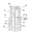
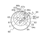
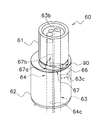
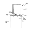
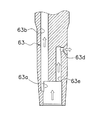
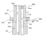
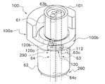
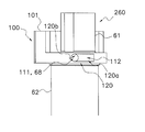
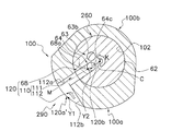
- FIG. 3 It is a schematic longitudinal cross-sectional view of the compressor which concerns on 1st Embodiment of this invention. It is a top view of the drive shaft of the compressor of FIG. The upper outflow path and the lower outflow path formed in the drive shaft are drawn with dotted lines. It is a schematic longitudinal cross-sectional view of the upper part of the drive shaft of the compressor of FIG. 3 is a cross-sectional view of the drive shaft cut along the SCS ′ cross section of FIG. FIG. 4 is a cross-sectional view taken along line IV-IV in FIG. 3. It is a perspective view of the upper part of the drive shaft of the compressor of FIG. The in-shaft oil supply path and the in-shaft oil discharge path formed in the drive shaft are drawn with dotted lines.
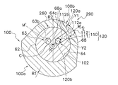
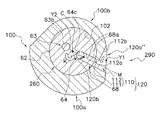
- FIG. 12 is a cross-sectional view taken along arrow XII-XII in FIG. An inflow path entrance is formed in the small diameter portion of the balance weight.
- FIG. 13 a longitudinal section in which the drive shaft is cut by a straight line M and a straight line M ′ in FIG. 12 is drawn. It is a perspective view of the upper part of the drive shaft of the compressor of FIG.
- FIG. 10 is an example of a cross-sectional view of a drive shaft of a compressor according to Modification C.
- FIG. FIG. 3 shows a cross-sectional view of a portion where an inflow path is formed.
- An inflow path inlet is formed in the large diameter portion of the balance weight.
- 10 is an example of a cross-sectional view of a drive shaft of a compressor according to Modification C.
- FIG. FIG. 3 shows a cross-sectional view of a portion where an inflow path is formed.
- An inflow path entrance is formed at the boundary between the large diameter portion and the small diameter portion of the balance weight.
- 10 is a cross-sectional view of a drive shaft of a compressor according to Modification D.
- the compressor 10 is a scroll compressor.
- the compressor 10 is connected to a refrigerant circuit of a refrigeration apparatus (not shown).
- the refrigerant circulates to perform a vapor compression refrigeration cycle.
- the refrigerant compressed by the compressor 10 radiates heat by the condenser, is depressurized by the depressurization mechanism, absorbs heat by the evaporator, and is sucked by the compressor 10 again.
- the compressor 10 mainly includes a casing 20, a compression mechanism 30, an electric motor 50, a drive shaft 60, a lower housing 70, and an oil pump 80.
- an in-shaft oil supply path 63 and an in-shaft oil discharge path 64 for supplying oil O (refrigeration oil) to the sliding portion of the compressor 10 are formed (FIG. 1). reference).
- the in-shaft oil discharge path 64 constitutes a part of the oil discharge path 90 for discharging the oil O from a crank chamber 35 and an oil recovery space 334 described later (see FIG. 1).
- the compressor 10 has a vertically long cylindrical casing 20.
- the casing 20 includes a cylindrical member 21 that is open at the top and bottom, and an upper lid 22 a and a lower lid 22 b that are respectively provided at the upper end and the lower end of the cylindrical member 21.
- the cylindrical member 21 and the upper lid 22a and the lower lid 22b are fixed by welding so as to keep airtightness.
- the casing 20 accommodates the components of the compressor 10 including the compression mechanism 30, the electric motor 50, the drive shaft 60, the lower housing 70, and the oil pump 80.
- An oil reservoir space 25 is formed at the bottom of the casing 20 as shown in FIG. In the oil reservoir space 25, oil O for lubricating the drive shaft 60 and the sliding portion of the compression mechanism 30 is stored.
- a suction pipe 23 that sucks in a refrigerant to be compressed by the compression mechanism 30 is provided in the upper part of the casing 20 so as to penetrate the upper lid 22a.
- the lower end of the suction pipe 23 is connected to a fixed scroll 31 of the compression mechanism 30 described later.
- the suction pipe 23 communicates with a compression chamber Sc of the compression mechanism 30 described later. Low pressure refrigerant in the refrigerant circuit is supplied to the compression chamber Sc via the suction pipe 23.
- the middle part of the cylindrical member 21 of the casing 20 is provided with a discharge pipe 24 through which the refrigerant discharged outside the casing 20 passes (see FIG. 1).
- the discharge pipe 24 is disposed such that an end of the discharge pipe 24 inside the casing 20 protrudes between an upper housing 33 of the compression mechanism 30 and an electric motor 50 which will be described later. High-pressure refrigerant in the refrigerant circuit compressed by the compression mechanism 30 is discharged from the discharge pipe 24.
- the compression mechanism 30 is driven by the electric motor 50 and compresses the refrigerant.
- the compression mechanism 30 is arrange
- the compression mechanism 30 mainly includes a fixed scroll 31, a movable scroll 32, an upper housing 33, and an Oldham coupling 34.
- the fixed scroll 31 is disposed above the upper housing 33.
- the movable scroll 32 is combined with the fixed scroll 31 to form the compression chamber Sc.
- the upper housing 33 forms a crank chamber 35 in which a pin bearing portion 323 of the movable scroll 32 described later is disposed.
- the upper housing 33 has an upper bearing portion 332 that supports the drive shaft 60 below the crank chamber 35 (see FIG. 1).
- the upper housing 33 has an upper shaft seal portion 333 below the upper bearing portion 332 (see FIG. 1).
- the Oldham coupling 34 prevents the movable scroll 32 from rotating.
- the fixed scroll 31 mainly includes a fixed side end plate 311, a fixed side wrap 312, and a peripheral edge 313.
- the fixed side wrap 312 and the peripheral edge 313 protrude downward from the surface of the fixed side end plate 311 on the movable scroll 32 side, in other words, from the lower surface of the fixed side end plate 311.
- the fixed side wrap 312 is formed in a spiral shape.
- the fixed side end plate 311 is formed in a disc shape.
- the fixed side wrap 312 and the movable side wrap 322 of the movable scroll 32 to be described later are combined so that the lower surface of the fixed side end plate 311 and the upper surface of the movable side end plate 321 of the movable scroll 32 to be described later face each other.
- a compression chamber Sc in which the refrigerant is compressed is formed between 31 and the movable scroll 32 (see FIG. 1).
- the fixed side end plate 311 has a discharge port 311a and a discharge space 311b (see FIG. 1).
- the discharge port 311a is formed in the center of the fixed side end plate 311 so as to penetrate the fixed side end plate 311 in the thickness direction (see FIG. 1).
- the discharge port 311a communicates the compression chamber Sc and the discharge space 311b (see FIG. 1).
- the discharge space 311 b communicates with a space below the upper housing 33 in the casing 20 via a refrigerant passage (not shown) formed in the fixed scroll 31 and the upper housing 33.
- the refrigerant compressed in the compression chamber Sc of the compression mechanism 30 passes through a refrigerant passage (not shown) and flows into the space below the upper housing 33.
- the space below the upper housing 33 is filled with the high-pressure refrigerant compressed by the compression mechanism 30.
- the peripheral edge portion 313 is formed in a thick ring shape and is disposed so as to surround the fixed side wrap 312 (see FIG. 1).
- the upper surface of the movable side end plate 321 of the movable scroll 32 described later comes into sliding contact with the lower surface of the peripheral edge portion 313.
- the movable scroll 32 which is an example of a movable part, is connected to the drive shaft 60.
- the movable scroll 32 is driven by an electric motor 50 connected to the drive shaft 60.
- the movable scroll 32 mainly has a movable side end plate 321, a movable side wrap 322, and a pin bearing portion 323.
- the movable side end plate 321 is formed in a disc shape.
- the movable side wrap 322 protrudes upward from the surface of the movable side end plate 321 on the fixed scroll 31 side, in other words, from the upper surface of the movable side end plate 321 (see FIG. 1).
- the movable side wrap 322 is formed in a spiral shape.
- the pin bearing portion 323 protrudes downward from the surface of the movable side end plate 321 on the electric motor 50 side, in other words, from the lower surface of the movable side end plate 321 (see FIG. 1).
- the pin bearing portion 323 is formed in a cylindrical shape, and the opening at the upper end of the cylinder is closed by the movable side end plate 321.
- the pin bearing portion 323 is accommodated in a crank chamber 35, which will be described later, formed by the upper housing 33.
- the movable scroll 32 and the drive shaft 60 are connected by inserting a pin shaft portion 61 of the drive shaft 60 described later into the pin bearing portion 323.
- a bearing metal 323a is fitted into the pin bearing portion 323.
- the pin shaft portion 61 inserted into the pin bearing portion 323 is rotatably supported by the bearing metal 323a.
- An oil communication chamber 36 is provided between the upper end surface of the pin shaft portion 61 of the drive shaft 60 inserted into the pin bearing portion 323 and the lower surface of the movable side end plate 321 inside the cylindrical pin bearing portion 323. Is formed (see FIG. 1).
- the oil communication chamber 36 communicates with an in-shaft oil supply path 63 formed in a drive shaft 60 described later.
- the oil communication chamber 36 is supplied with oil O from the in-shaft oil supply path 63.
- a pin shaft channel (not shown) extending in the vertical direction is formed between the pin shaft portion 61 and the bearing metal 323a.
- the pin shaft channel has an upper end opened to the oil communication chamber 36 and a lower end opened to the crank chamber 35.
- Oil O flows from the oil communication chamber 36 into the pin shaft channel.
- the oil O that has flowed into the pin shaft channel is supplied to the sliding portion between the pin shaft portion 61 and the bearing metal 323a.
- the oil O that has been supplied to the sliding portion between the pin shaft portion 61 and the bearing metal 323 a flows into the crank chamber 35 formed by the upper housing 33.
- An oil passage 321 a is formed inside the movable side end plate 321.
- the oil passage 321a extends from the opening on the lower surface of the movable side end plate 321 communicating with the oil communication chamber 36 to the inside of the disk-shaped movable side end plate 321 outward in the radial direction, and further upwards to extend the movable side end plate 321. Open on the top surface.
- the upper housing 33 is a cylindrical member that extends vertically.
- the upper housing 33 is press-fitted into the cylindrical member 21, and the outer peripheral surface thereof is joined to the inner surface of the cylindrical member 21 over the entire circumferential direction (see FIG. 1).
- the fixed scroll 31 is fixed to the upper housing 33 with the lower surface of the peripheral edge 313 of the fixed scroll 31 and the upper end surface of the upper housing 33 facing each other (see FIG. 1).
- a drive shaft 60 is inserted into the cylindrical upper housing 33 (see FIG. 1).
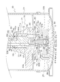
- the upper housing 33 is formed with a concave portion 331 formed so as to be recessed downward at the center of the upper surface. Further, as shown in FIG. 1, the upper housing 33 includes an upper bearing portion 332 disposed below the concave portion 331 and an upper shaft seal portion 333 disposed below the upper bearing portion 332.
- the recess 331 forms a crank chamber 35 in which the pin bearing portion 323 of the movable scroll 32 is disposed (see FIG. 1). Inside the crank chamber 35, a connecting portion between the pin shaft portion 61 of the drive shaft 60 inserted into the upper housing 33 and the movable scroll 32 is housed inside (see FIG. 1). In other words, the crank chamber 35 accommodates the pin bearing portion 323 of the movable scroll 32 into which the pin shaft portion 61 of the drive shaft 60 is inserted (see FIG. 1).
- the upper bearing portion 332 is an example of a bearing portion.
- the upper bearing portion 332 is disposed below the crank chamber 35 (see FIG. 1).
- a bearing metal 332a is provided inside the upper bearing portion 332 (see FIG. 1).
- the bearing metal 332 a rotatably supports the main shaft 62 of the drive shaft 60 inserted into the upper bearing portion 332 of the upper housing 33.
- the upper bearing portion 332 is formed with an upper bearing oil drain passage 332b extending in the vertical direction (see FIG. 1).
- the lower end of the upper bearing oil drain passage 332b communicates with an oil recovery space 334 disposed below the upper bearing portion 332 (see FIG. 1).
- the oil recovery space 334 will be described later.
- the upper end of the upper bearing oil drain passage 332 b communicates with the crank chamber 35 disposed above the upper bearing portion 332.
- the upper bearing oil drain passage 332 b is a passage that guides a part of the oil O supplied to the sliding portion between the bearing metal 332 a of the upper bearing portion 332 and the main shaft 62 of the drive shaft 60 to the crank chamber 35. .
- the oil O that has been supplied to the sliding portion between the bearing metal 332a of the upper bearing portion 332 and the main shaft 62 of the drive shaft 60 the oil O that does not flow into the crank chamber 35 enters the oil recovery space 334. Inflow.
- the upper shaft seal portion 333 is disposed below the upper bearing portion 332 (see FIG. 1).
- the upper shaft seal portion 333 is formed in a cylindrical shape.
- the inner diameter of the upper shaft seal portion 333 is substantially equal to the outer diameter of the main shaft 62 of the drive shaft 60 disposed inside the upper shaft seal portion 333.
- the inner diameter of the upper shaft seal portion 333 is slightly larger than the outer diameter of the main shaft 62 of the drive shaft 60 disposed inside the upper shaft seal portion 333.
- the upper shaft seal portion 333 prevents the oil O from leaking from the lower part of the gap between the upper housing 33 and the drive shaft 60.
- An annular space is formed between the upper bearing portion 332 and the upper shaft seal portion 333 and between the upper housing 33 and the drive shaft 60 so as to surround the drive shaft 60. Even if the annular space is formed between the main shaft 62 and the upper housing 33 by reducing the outer diameter of the main shaft 62 of the drive shaft 60, the main shaft 62 and the upper housing are increased by increasing the inner diameter of the upper housing 33. 33 may be formed.
- This space functions as an oil recovery space 334 (see FIG. 1).
- the oil recovery space 334 is formed in the lower part of the upper housing 33. Part of the oil O that has been supplied to the sliding portion between the bearing metal 332 a of the upper bearing portion 332 and the main shaft 62 of the drive shaft 60 flows into the oil recovery space 334.
- the oil recovery space 334 communicates with a second inflow path 64b (described later) of the in-shaft oil discharge path 64 formed in the drive shaft 60.
- the oil O that has flowed into the oil recovery space 334 is discharged to the oil reservoir space 25 below the casing 20 via the in-shaft oil discharge path 64.
- the discharge of the oil O from the oil recovery space 334 will be described later.
- the upper shaft seal portion 333 is provided with an upper shaft seal ring 41 (see FIG. 1).
- an upper shaft seal ring 41 is disposed between the upper shaft seal portion 333 and the drive shaft 60 below the upper shaft seal portion 333 (see FIG. 1).
- the upper shaft seal ring 41 is disposed in an annular seal ring groove 41a formed in a region of the main shaft 62 of the drive shaft 60 facing the upper shaft seal portion 333 (see FIG. 1).
- the upper shaft seal ring 41 is disposed in an annular seal ring groove formed in the upper shaft seal portion 333 instead of being disposed in the seal ring groove 41a formed in the main shaft 62 of the drive shaft 60. Also good.
- the upper shaft seal ring 41 is made of metal or resin.
- the upper shaft seal ring 41 for example, a metal material or a resin material excellent in high temperature characteristics is used.
- the upper shaft seal ring 41 is formed in an annular shape and has a joint (not shown) (not shown).
- the shape of the joint is, for example, an angle cut shape.
- the shape of the joint is not limited to this, and may be, for example, a step cut shape.
- the shape of the joint may be determined as appropriate.
- the diameter A1 of the main shaft 62 of the drive shaft 60 of the portion to which the upper shaft seal ring 41 is attached at the height h1 (see FIG. 1) in the axial direction of the upper shaft seal ring 41 (see FIG. 1, see the seal ring groove 41a).
- the value of the ratio to the diameter of the portion not formed is 0.047, but is not limited thereto.
- the value of the ratio of the height h1 in the axial direction of the upper shaft seal ring 41 to the diameter A1 of the main shaft 62 of the drive shaft 60 in the portion where the upper shaft seal ring 41 is attached is 0.04 or more and less than 0.07.
- the value of the ratio of the radial thickness w1 (see FIG. 1) of the upper shaft seal ring 41 to the diameter A1 of the main shaft 62 of the drive shaft 60 in the portion where the upper shaft seal ring 41 is attached is 0.040.
- the present invention is not limited to this.
- the value of the ratio of the radial thickness w1 of the upper shaft seal ring 41 to the diameter A1 of the main shaft 62 of the drive shaft 60 in the portion where the upper shaft seal ring 41 is attached is 0. It is preferably 0.03 or more and less than 0.06.
- the Oldham Joint 34 is provided on the upper surface of the upper housing 33 (see FIG. 1).
- the Oldham coupling 34 is slidably fitted into the movable side end plate 321 of the movable scroll 32 and the upper housing 33.
- the Oldham coupling 34 prevents the movable scroll 32 driven by the electric motor 50 from rotating. Due to the action of the Oldham coupling 34, the movable scroll 32 revolves with respect to the fixed scroll 31 without rotating.
- the electric motor 50 is disposed below the upper housing 33 of the compression mechanism 30 (see FIG. 1).
- the electric motor 50 includes a stator 51 fixed to the inner wall surface of the cylindrical member 21 and a rotor 53 that is rotatably accommodated with a slight gap (air gap) inside the stator 51 (see FIG. 1).
- the stator 51 has a cylindrical stator core 52 and windings (not shown) wound around the stator core 52.
- a core cut 52a extending in the vertical direction is formed on the outer peripheral surface of the stator core 52 (see FIG. 1). In the core cut 52 a portion, a gap is formed between the stator core 52 and the cylindrical member 21 of the casing 20.
- the compressor 10 can improve motor efficiency compared with the compressor of the type which returns the oil which accumulates in a crank chamber to an oil reservoir space through the clearance gap of a core cut part.
- the rotor 53 is formed in a cylindrical shape.
- the rotor 53 and the drive shaft 60 are connected by inserting the drive shaft 60 into the rotor 53.
- the drive shaft 60 is also connected to the movable scroll 32. That is, the rotor 53 is connected to the movable scroll 32 via the drive shaft 60.
- the electric motor 50 drives the movable scroll 32 by rotating the rotor 53.
- the drive shaft 60 extends in the vertical direction along the axis of the cylindrical member 21 of the casing 20 (see FIG. 1).
- the drive shaft 60 is connected to the rotor 53 of the electric motor 50 and transmits the driving force of the electric motor 50 to the movable scroll 32.
- the drive shaft 60 has a main shaft 62 whose central axis coincides with the central axis of the cylindrical member 21, and a pin shaft portion 61 that is eccentric with respect to the main shaft 62 (see FIG. 1).
- the pin shaft portion 61 is an example of an eccentric portion.
- the pin shaft portion 61 is formed to have a smaller diameter than the main shaft 62.
- the pin shaft portion 61 is inserted into the pin bearing portion 323 of the movable scroll 32 as described above.
- the pin shaft portion 61 is rotatably supported by a bearing metal 323a disposed inside the pin bearing portion 323.
- the main shaft 62 is rotatably supported by a bearing metal 332a of the upper bearing portion 332 of the upper housing 33 and a bearing metal 71a of a lower bearing portion 71 of the lower housing 70 described later (see FIG. 1).
- the main shaft 62 is connected to the rotor 53 of the electric motor 50 between the upper bearing portion 332 and the lower bearing portion 71 (see FIG. 1).
- the drive shaft 60 rotates around the rotation center C in plan view (see FIGS. 2 and 4).
- the rotation center C is the center position of the main shaft 62 in plan view.
- the main shaft 62 (drive shaft 60) rotates counterclockwise in plan view (see the rotation direction K in FIG. 4).
- an in-shaft oil supply path 63 for supplying oil O to the sliding portion of the compressor 10 is formed as shown in FIG. Further, as shown in FIG. 1, the drive shaft 60 communicates with the crank chamber 35 and the oil recovery space 334, and in the shaft for discharging the oil O accumulated in the crank chamber 35 and the oil recovery space 334.
- An oil drain path 64 is formed. The in-shaft oil supply path 63 and the in-shaft oil discharge path 64 will be described later.
- An oil pump shaft receiver 69 is fixed to the lower end of the main shaft 62 of the drive shaft 60 (see FIG. 1). Specifically, an oil pump shaft receiver 69 is inserted and fixed in an opening of an inflow passage 63a of an in-shaft oil supply passage 63 described later formed at the lower end of the main shaft 62.
- the oil pump shaft receiver 69 is a hollow member. As will be described later, an oil pump shaft 84 of the oil pump 80 is inserted into the hollow portion of the oil pump shaft receiver 69 from the lower end side (see FIG. 9). Inside the oil pump shaft 84, an axial relay path 84b is formed as described later (see FIG. 9). The axial relay path 84b communicates with the inflow path 63a of the in-axis oil supply path 63 into which the oil pump shaft receiver 69 is inserted (see FIG. 9).
- the lower housing 70 is disposed at the lower part in the casing 20 (see FIG. 1).
- the lower housing 70 is disposed below the electric motor 50.
- the lower housing 70 is a cylindrical member that extends vertically. A part of the outer peripheral surface of the lower housing 70 protrudes toward the cylindrical member 21 of the casing 20 (see FIG. 10), and is fixed to the cylindrical member 21.
- a drive shaft 60 is inserted into the cylindrical lower housing 70 (see FIG. 1).
- the lower housing 70 has a lower shaft seal portion 77 at the upper portion thereof (see FIG. 1). Further, the lower housing 70 has a lower bearing portion 71 below the lower shaft seal portion 77 (see FIG. 1). A recess 72 that is recessed upward is formed in the lower portion of the lower housing 70 (see FIG. 1). An oil pump 80 is fixed to the lower end surface of the lower housing 70 so as to close the opening at the bottom of the recess 72 (see FIG. 1).
- the lower bearing 71 supports the drive shaft 60.
- a bearing metal 71a is provided inside the lower bearing portion 71 (see FIG. 1).
- the bearing metal 71 a rotatably supports the main shaft 62 of the drive shaft 60 disposed in the lower bearing portion 71 of the lower housing 70.
- the lower shaft seal portion 77 is formed in a cylindrical shape.
- the inner diameter of the lower shaft seal portion 77 is substantially equal to the outer diameter of the main shaft 62 of the drive shaft 60 disposed inside the lower shaft seal portion 77.
- the inner diameter of the lower shaft seal portion 77 is slightly larger than the outer diameter of the main shaft 62 of the drive shaft 60 disposed inside the lower shaft seal portion 77.
- the lower shaft seal portion 77 prevents oil O from leaking from the upper part of the gap between the lower housing 70 and the drive shaft 60.
- annular space is formed between the lower bearing portion 71 and the lower shaft seal portion 77 and between the lower housing 70 and the drive shaft 60 so as to surround the drive shaft 60 (see FIG. 9). ). Even if the annular space is formed between the main shaft 62 and the lower housing 70 by reducing the outer diameter of a part of the main shaft 62 of the drive shaft 60, the inner diameter of a part of the lower housing 70 is reduced. And may be formed between the main shaft 62 and the lower shaft seal portion 77. This space functions as an annular space 76 (see FIG. 1). The annular space 76 is a space adjacent to the bearing metal 71a of the lower bearing portion 71 (see FIG. 9).
- the annular space 76 communicates with an oil discharge main path 64c of an in-shaft oil discharge path 64 described later and an outflow path 64d of an in-shaft oil discharge path 64 described later (see FIG. 9). Oil O that has flowed through the main oil drain path 64c and the outflow path 64d flows into the annular space 76. A part of the oil O after being supplied to the sliding portion between the bearing metal 71 a of the lower bearing portion 71 and the main shaft 62 of the drive shaft 60 flows into the annular space 76.
- the annular space 76 communicates with a lower housing oil drain path 74 formed in the lower housing 70.
- the lower housing internal oil drain path 74 is an example of an oil path.
- the lower housing internal oil drain passage 74 communicates with a lower space 78 (see FIG. 9) surrounded by the recess 72 of the lower housing 70 and the oil pump 80.
- the oil O flowing into the annular space 76 flows into the lower space 78 through the lower housing drain oil passage 74. Further, a part of the oil O after being supplied to the sliding portion between the bearing metal 71a of the lower bearing portion 71 and the main shaft 62 of the drive shaft 60 is directly (without passing through the oil draining path 74 in the lower housing). It flows into the lower space 78.
- the oil O that has flowed into the lower space 78 is guided to an oil discharge pump portion 80B of an oil pump 80, which will be described later, and flows into the oil reservoir space 25. That is, the lower housing internal oil discharge path 74 communicates the annular space 76 and the oil reservoir space 25 via the lower space 78 and the oil discharge pump portion 80B.
- a lower shaft seal ring 42 is disposed on the lower shaft seal portion 77. Since the lower shaft seal ring 42 is disposed in the lower shaft seal portion 77, the leakage of the oil O from the upper portion of the lower housing 70 can be prevented, and oil rising can be suppressed.
- a lower shaft seal ring 42 is disposed between the lower shaft seal portion 77 and the drive shaft 60 at the upper portion of the lower shaft seal portion 77 (see FIG. 9).
- the lower shaft seal ring 42 is disposed in an annular seal ring groove 42a formed in a region of the main shaft 62 of the drive shaft 60 facing the lower shaft seal portion 77 (see FIG. 9).
- the lower shaft seal ring 42 is disposed in an annular seal ring groove formed in the lower shaft seal portion 77 instead of being disposed in the seal ring groove 42a formed in the main shaft 62 of the drive shaft 60. Also good.
- the lower shaft seal ring 42 is made of metal or resin.
- the lower shaft seal ring 42 for example, a metal material or a resin material excellent in high temperature characteristics is used.
- the lower shaft seal ring 42 is formed in an annular shape, and has a joint (not shown) (not shown).
- the shape of the joint is, for example, an angle cut shape.
- the shape of the joint is not limited to this, and may be, for example, a step cut shape.
- the shape of the joint may be determined as appropriate.
- the diameter A2 of the main shaft 62 of the drive shaft 60 of the portion to which the lower shaft seal ring 42 is attached at the height h2 (see FIG. 9) in the axial direction of the lower shaft seal ring 42 (see FIG. 9, the seal ring groove 42a).
- the value of the ratio to the diameter of the non-formed portion is 0.053, but is not limited thereto.
- the value of the ratio of the axial height h2 of the lower shaft seal ring 42 to the diameter A2 of the main shaft 62 of the drive shaft 60 of the portion where the lower shaft seal ring 42 is attached is 0.04 or more and less than 0.07.
- the ratio of the radial thickness w2 (see FIG. 9) of the lower shaft seal ring 42 to the diameter A2 of the main shaft 62 of the drive shaft 60 in the portion where the lower shaft seal ring 42 is attached is 0.045.
- the present invention is not limited to this.
- the value of the ratio of the radial thickness w2 of the lower shaft seal ring 42 to the diameter A2 of the main shaft 62 of the drive shaft 60 in the portion where the lower shaft seal ring 42 is attached is 0. It is preferably 0.03 or more and less than 0.06.
- the in-shaft oil supply path 63 is an example of an oil supply path.
- the in-shaft oil supply path 63 is an oil path for supplying the oil O in the oil reservoir space 25 supplied by an oil supply pump part 80 ⁇ / b> A of the oil pump 80 described later to each sliding part of the compressor 10.
- the in-shaft oil supply path 63 is formed in the drive shaft 60 (see FIG. 1).
- the in-shaft oil supply path 63 conveys the oil O in the oil reservoir space 25 to the upper end of the pin shaft portion 61 of the drive shaft 60 disposed in the crank chamber 35. That is, the in-shaft oil supply path 63 carries the oil O in the oil reservoir space 25 to the crank chamber 35.
- the in-shaft oil supply path 63 mainly includes an inflow path 63a, a main oil supply path 63b, an upper outflow path 63c, and a lower outflow path 63d.
- FIG. 3 is a cross-sectional view of the upper portion of the drive shaft 60 taken along the SCS ′ cross section in FIG.
- FIG. 7 is a cross-sectional view of the lower portion of the drive shaft 60 cut along the SCT cross section in FIG. C in FIG. 2 indicates the rotation center C of the drive shaft 60.
- the inflow path 63a is a recess opening at the lower end of the drive shaft 60 (see FIG. 7).
- the inflow path 63a is formed in the central portion of the drive shaft 60 so as to be recessed upward from the lower end (see FIG. 7).
- An oil pump shaft receiver 69 is inserted into the inflow path 63a from the opening at the lower end.
- an oil pump shaft 84 of an oil pump 80 described later is inserted into the hollow oil pump shaft receiver 69.
- the inflow path 63a communicates with an axial relay path 84b formed in the oil pump shaft 84 of the oil pump 80 (see FIG. 9).
- the oil O in the oil reservoir space 25 is supplied from the inflow path 63a to the in-shaft oil supply path 63 by the oil supply pump portion 80A of the oil pump 80.
- the oil supply main path 63b extends in the drive shaft 60 in the axial direction, that is, in the vertical direction.
- the lower end of the oil supply main path 63b communicates with the inflow path 63a.
- the upper end of the oil supply main path 63 b opens at the upper end surface of the pin shaft portion 61 of the drive shaft 60.
- the oil supply main path 63 b communicates with the oil communication chamber 36.
- the upper outflow path 63c extends in the drive shaft 60 from the oil supply main path 63b in a direction crossing the axial direction.
- the upper outflow path 63c extends in the drive shaft 60 from the oil supply main path 63b in a direction orthogonal to the axial direction (see FIG. 3).
- the upper outflow path 63c extends in the drive shaft 60 in the radial direction from the oil supply main path 63b (see FIG. 2).
- the upper outflow path 63 c opens at the outer peripheral surface of the drive shaft 60 in the upper bearing portion 332 of the upper housing 33. Oil O flowing out of the opening of the outer peripheral surface of the drive shaft 60 in the upper outflow path 63 c is supplied to the sliding portion between the bearing metal 332 a of the upper bearing portion 332 and the main shaft 62 of the drive shaft 60.
- the lower outflow path 63d extends in the drive shaft 60 from the oil supply main path 63b in a direction crossing the axial direction (see FIG. 7).
- the lower outflow path 63d extends in the drive shaft 60 from the oil supply main path 63b in a direction orthogonal to the axial direction (see FIG. 7).
- the lower outflow path 63d extends in the drive shaft 60 in the radial direction from the oil supply main path 63b (see FIG. 2).
- the lower outflow path 63 d opens at the outer peripheral surface of the drive shaft 60 in the lower bearing portion 71 of the lower housing 70. Oil O flowing out of the opening of the outer peripheral surface of the drive shaft 60 in the lower outflow path 63d is supplied to the sliding portion between the bearing metal 71a of the lower bearing portion 71 and the main shaft 62 of the drive shaft 60.
- the opening on the outer peripheral surface of the drive shaft 60 in the upper outflow path 63c and the opening on the outer peripheral surface of the drive shaft 60 in the lower outflow path 63d are shifted by about 180 degrees with respect to the rotation center C of the drive shaft 60. (See FIG. 2).
- the upper outflow path 63c and the lower outflow path 63d generally extend on a straight line passing through the rotation center C of the drive shaft 60 in plan view.
- the upper outflow path 63c and the lower outflow path 63d generally extend on a straight line ST extending through the rotation center C of the drive shaft 60 in plan view.
- the opening on the outer peripheral surface of the drive shaft 60 of the upper outflow path 63c and the opening on the outer peripheral surface of the drive shaft 60 of the lower outflow path 63d are arranged symmetrically with respect to the rotation center C of the drive shaft 60.
- oil film generation at the sliding portion of the upper bearing portion 332 and the sliding portion of the lower bearing portion 71 is facilitated.
- the upper bearing portion 332 and the lower bearing portion 71 receive a load in a direction (angle) that is generally opposite to the rotation center C of the drive shaft 60 (approximately 180 degrees different).
- the form in which the upper bearing portion 332 and the lower bearing portion 71 receive the load is a so-called rotational load in which the magnitude of the load is substantially constant and the load direction varies in synchronization with the shaft rotation. Therefore, if the upper bearing portion 332 and the lower bearing portion 71 are designed to provide an opening for the outflow path on the side opposite to the direction (approximately the minimum oil film thickness position angle) for supporting the load, the upper bearing portion 332 and the lower bearing portion will be described.
- the flow rate of the oil O supplied to the part 71 can be increased most.
- an oil supply main path 63 b that extends in the axial direction from the inflow path 63 a at a position symmetrical to the oil supply main path 63 b with respect to the rotation center C of the drive shaft 60.
- the lower outflow path 63d may be connected to the lower bearing dedicated path 63e instead of the oil supply main path 63b, and the oil O may be supplied to the lower outflow path 63d via the lower bearing dedicated path 63e.
- the flow of the oil O flowing through the lower outflow path 63 d also becomes a flow along the centrifugal force, and the oil O is easily supplied to the lower bearing portion 71.
- the oil discharge route 90 is used to remove the oil O in the crank chamber 35 and the oil recovery space 334 and the oil O supplied to the lower bearing portion 71 from the oil pump 80. This is an oil path leading to the pump unit 80B.
- the oil drainage path 90 mainly includes an in-shaft oil drainage path 64, an annular space 76, a lower housing drainage oil path 74, and a lower space 78 surrounded by the recess 72 of the lower housing 70 and the oil pump 80. Included (see FIG. 1).
- the in-shaft oil discharge path 64 guides the oil O in the crank chamber 35 and the oil recovery space 334 to the annular space 76 formed around the main shaft 62 of the drive shaft 60.
- the oil O in the annular space 76 is conveyed to the lower space 78 through the lower housing drain oil passage 74.
- the oil O collected in the crank chamber 35 includes the oil O after being supplied to the sliding portion between the pin shaft portion 61 of the drive shaft 60 and the bearing metal 323a of the pin bearing portion 323.
- the oil O accumulated in the crank chamber 35 is supplied to the sliding portion between the main shaft 62 of the drive shaft 60 and the bearing metal 332a of the upper bearing portion 332, and then passes through the upper bearing oil drain passage 332b.
- Oil O flowing into the The oil O flowing into the oil recovery space 334 includes the oil O after being supplied to the sliding portion between the main shaft 62 of the drive shaft 60 and the bearing metal 332a of the upper bearing portion 332.
- the oil O flowing into the annular space 76 is supplied to the sliding portion between the oil O flowing through the in-shaft oil discharge path 64 and the main shaft 62 of the drive shaft 60 and the bearing metal 71a of the lower bearing portion 71. Part of oil O.
- the in-shaft oil discharge path 64 mainly has a first inflow path 67, a second inflow path 64b, a main oil discharge path 64c, and an outflow path 64d (see FIG. 1).
- the first inflow path 67 communicates the oil drain main path 64c and the crank chamber 35 (see FIG. 1).
- the first inflow path 67 is formed at the base of the pin shaft portion 61 (see FIGS. 3, 5 and 6).
- the pin shaft portion 61 of the drive shaft 60 is disposed in the crank chamber 35 formed by the upper housing 33.
- the space in the in-shaft oil discharge path 64 (the space in the pin shaft portion 61), A space different from the crank chamber 35 is defined. That is, in the cross-sectional view of FIG. 4, the space inside the first inflow path 67 and the oil drain main path 64 c formed inside the outer peripheral edge of the pin shaft portion 61 is defined as a space different from the crank chamber 35. .
- the oil drain main path 64c is a hole extending in the axial direction, that is, in the vertical direction, inside the drive shaft 60.
- the oil drain main path 64c is formed in a circular shape in plan view.
- the oil drain main path 64 c extends from the upper end surface of the pin shaft portion 61 of the drive shaft 60 to the lower portion of the drive shaft 60.
- the opening at the upper end of the oil drain main path 64c is closed by a plug 64e (see FIG. 1). For this reason, the oil drain main path 64 c does not communicate with the oil communication chamber 36 formed above the pin shaft portion 61.
- the first inflow path 67 mainly has a suction hole 65 and an introduction portion 66 (see FIGS. 3 and 4).
- the suction hole 65 is an example of the vicinity of the outlet.
- the suction hole 65 is a hole that opens to the oil drain main path 64c.
- the opening of the suction hole 65 to the oil drain main path 64c is referred to as an inflow path outlet 67b (see FIGS. 4 to 6). That is, the suction hole 65 is provided in the vicinity of the inflow path outlet 67b, more specifically, adjacent to the inflow path outlet 67b.
- the inflow path outlet 67b is an opening formed at the outer peripheral edge of the oil drain main path 64c.
- the inflow path outlet 67b is an opening formed on the outer peripheral surface of the cylindrical member by opening the suction hole 65 when the oil drain main path 64c is assumed to be a substantial cylindrical member. is there.
- the inflow route outlet 67b is arranged in a section indicated by a double-headed arrow in FIG. 4 on the outer peripheral edge of the oil drainage main route 64c in plan view.
- the suction hole 65 extends linearly from the oil drain main path 64c, in other words, from the inflow path outlet 67b.
- the suction hole 65 is a hole formed in a circular shape when viewed from the side (when viewed from a direction orthogonal to the axial direction of the drive shaft 60) (see FIG. 6). Therefore, the inflow path outlet 67b is also formed in a circular shape in a side view (see FIG. 6).
- the suction hole 65 extends along a straight line that intersects the axial direction of the drive shaft 60.
- the suction hole 65 extends along a straight line orthogonal to the axial direction of the drive shaft 60.
- the suction hole 65 is along a straight line L passing through the rotation center C of the drive shaft 60 (center of the main shaft 62) and the centroid Z2 of the inflow path outlet 67b in a plan view and orthogonal to the axial direction of the drive shaft 60. (See FIG. 3).
- centroid Z2 of the inflow path outlet 67b in plan view is a section where the inflow path outlet 67b on the outer peripheral edge of the oil drain main path 64c is disposed (on the outer peripheral edge of the oil main path 64c in FIG. 4).
- the suction hole 65 has a pair of straight portions 65a extending linearly from the inflow path outlet 67b in plan view (see FIG. 4). Both straight portions 65a extend from the inflow path outlet 67b in parallel to the straight line L toward the outside of the pin shaft portion 61 (see the direction of the arrow in the direction B in FIG. 4).
- the introduction portion 66 is formed at the base portion of the pin shaft portion 61 so as to wind the inside of the pin shaft portion 61 from the outer peripheral surface of the pin shaft portion 61 (see FIG. 5).
- the introduction portion 66 is disposed on one of the outer peripheral edge of the pin shaft portion 61 (a section indicated by a double arrow in FIG. 4 where an inflow path inlet 67a described later is formed) and the straight portion 65a of the suction hole 65.
- This is a space surrounded by a first surface 66 a that extends continuously, a second surface 66 b that extends in a direction orthogonal to the straight line L, and the suction hole 65.
- the introduction portion 66 is formed to extend in a direction orthogonal to the straight line L (a direction in which the second surface 66b extends) longer than a direction of the straight line L (a direction in which the first surface 66a extends) in plan view.
- the introduction part 66 is a space communicating with the suction hole 65 (see FIGS. 3 and 4).
- the introduction portion 66 is a space communicating with the crank chamber 35 (see FIGS. 3 and 4). In other words, the introduction part 66 opens into the crank chamber 35.
- the opening of the introduction portion 66 into the crank chamber 35 is called an inflow path inlet 67a (see FIGS. 4 to 6).
- the inflow path inlet 67a is an opening formed on the outer peripheral edge of the pin shaft portion 61 (see FIG. 5).
- the inflow path inlet 67a is disposed in a section indicated by a double-headed arrow in FIG. 4 on the outer peripheral edge of the pin shaft portion 61 in plan view.
- the inflow path inlet 67a is formed in a rectangular shape that extends long in the horizontal direction in a side view from the direction facing the second surface 66b of the introduction portion 66 (see FIG. 6).
- the oil O in the crank chamber 35 flows into the introduction portion 66 through the inflow path inlet 67a.
- An inflow path inlet 67a (inflow path inlet 67a that opens to the crank chamber 35) that is an inlet of oil O from the crank chamber 35 to the first inflow path 67, and an oil O from the first inflow path 67 to the exhaust oil main path 64c.
- the inflow path outlet 67b (the inflow path outlet 67b opened to the oil drain main path 64c), which is the outlet of
- the area of the inflow path inlet 67a formed on the outer peripheral surface of the pin shaft portion 61 is larger than the area of the inflow path outlet 67b formed on the outer peripheral edge of the oil drain main path 64c (see FIGS. 5 and 6).
- the inflow path inlet 67a is biased forward in the rotational direction K of the drive shaft 60 from the inflow path outlet 67b.
- the centroid Z1 of the inflow path inlet 67a is located on the front side in the rotational direction K of the drive shaft 60 with respect to the straight line L extending in the direction B through the centroid Z2 of the inflow path outlet 67b. (See FIG. 4).
- the centroid Z1 of the inflow path inlet 67a in a plan view is a section where the inflow path inlet 67a on the outer peripheral edge of the pin shaft portion 61 is arranged (a double arrow on the outer peripheral edge of the pin shaft portion 61 in FIG. 4).
- centroid of the virtual figure when a figure with a very small width extending along the outer peripheral edge of the pin shaft portion 61 is assumed in the section shown).
- centroid Z1 of the inflow path inlet 67a rotates with respect to the straight line L extending from the rotation center C of the drive shaft 60 through the centroid Z2 of the inflow path outlet 67b. It is located on the front side in the direction K (see FIG. 4).
- the area of the inflow path inlet 67a is configured to be larger than the area of the inflow path outlet 67b, so that the area of the inflow path inlet 67a is not larger than the area of the inflow path outlet 67b.
- the oil O in the chamber 35 is easily guided to the oil exhaust main path 64 c by the first inflow path 67.
- the inflow path inlet 67a is biased forward in the rotational direction K of the drive shaft 60 relative to the inflow path outlet 67b, so that when the drive shaft 60 rotates, the inflow direction K
- the oil O is easily guided to the introduction portion 66 from the inflow path inlet 67a disposed on the front side of the inflow path outlet 67b, and the oil O is easily guided to the oil drain main path 64c.
- the introduction portion 66 has a first surface 66a that extends in a direction intersecting the rotation direction K.
- the first surface 66a is an example of a guide surface.
- the first surface 66a is linear with the straight portion 65a of the suction hole 65 on the rear side in the rotation direction K of the drive shaft 60 (the straight portion 65a of the suction hole 65 on the rear side in the rotation direction K with respect to the straight line L) in plan view. (See FIG. 4). That is, the introduction portion 66 has a first surface 66a extending in parallel with the straight line L in plan view (see FIG. 4).
- the suction hole 65 is formed by a drill, and then the introduction portion 66 is formed by an end mill.
- transducing part 66 is an illustration, and is not limited to this.
- Various processing methods can be applied to the method of forming the suction hole 65 and the introduction portion 66.
- the second inflow path 64b communicates the main oil drain path 64c and the oil recovery space 334.
- the second inflow path 64b extends in the drive shaft 60 from the oil drain main path 64c in a direction crossing the axial direction.
- the second inflow path 64b extends in the drive shaft 60 in a direction orthogonal to the axial direction.
- the second inflow path 64b extends in the radial direction in the drive shaft 60 from the oil drain main path 64c.
- the second inflow path 64 b is formed at a height position of the oil recovery space 334 of the upper housing 33.
- the second inflow path 64 b opens on the outer peripheral surface of the drive shaft 60 in the oil recovery space 334 formed above the upper shaft seal portion 333.
- the second inflow path 64b has one end communicating with the oil recovery space 334 and the other end communicating with the oil drain main path 64c.
- the oil O in the oil recovery space 334 flows into the in-shaft oil discharge path 64 from the opening of the second inflow path 64b.
- the oil O after being supplied to the sliding portion between the bearing metal 332 a of the upper bearing portion 332 and the main shaft 62 of the drive shaft 60. Are all introduced into the crank chamber 35, and are introduced from the first inflow path 64a into the oil drain main path 64c.
- the oil O after being supplied to the sliding portion between the bearing metal 332a of the upper bearing portion 332 and the main shaft 62 of the drive shaft 60 is second.
- the inflow path 64b can also flow into the oil drain main path 64c. Therefore, the oil O can be prevented from being excessively accumulated in the crank chamber 35.
- the outflow path 64d extends in the drive shaft 60 from the lower end of the oil drain main path 64c in a direction crossing the axial direction. Particularly, here, the outflow path 64d extends in the drive shaft 60 from the lower end of the oil drain main path 64c in a direction orthogonal to the axial direction. The outflow path 64d extends in the drive shaft 60 in the radial direction from the lower end of the oil drain main path 64c.
- the outflow path 64 d is open to the outer peripheral surface of the main shaft 62 of the drive shaft 60 in an annular space 76 formed between the lower housing 70 and the main shaft 62 of the drive shaft 60. That is, the outflow path 64 d communicates with the annular space 76.
- the oil O that has flowed into the annular space 76 is discharged to a lower space 78 surrounded by the recess 72 of the lower housing 70 and the oil pump 80 via a lower housing drain oil passage 74 formed in the lower housing 70.
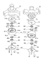
- Oil Pump 80 is a so-called double trochoidal positive displacement pump.
- the oil pump 80 is fixed to the lower end surface of the lower housing 70 with bolts 83 as shown in FIG.
- the oil pump 80 mainly includes a thrust plate 73, a pump body 81, a pump cover 82, an oil pump shaft 84, a lower outer rotor 85, a lower inner rotor 86, an upper outer rotor 87, and an upper inner rotor 88.
- the oil pump 80 includes an oil supply pump portion 80A that supplies the oil O in the oil reservoir space 25 to the in-shaft oil supply path 63, and a drain that discharges the oil O in the crank chamber 35 to the oil reservoir space 25 through the oil discharge path 90.
- Oil pump unit 80B (see FIG. 9).
- Oil supply pump unit 80A is an example of an oil supply pump.
- the oil discharge pump unit 80B is an example of an oil discharge pump.
- the oil supply pump portion 80A includes a lower outer rotor 85 and a lower inner rotor 86 (see FIG. 9).
- the oil discharge pump unit 80B includes an upper outer rotor 87 and an upper inner rotor 88 (see FIG. 9).
- a driving force is transmitted by the oil pump shaft 84 to the lower inner rotor 86 of the oil supply pump portion 80A and the upper inner rotor 88 of the oil discharge pump portion 80B.
- the oil pump shaft 84 is connected to the lower part of the drive shaft 60, and when the drive shaft 60 rotates, the oil pump shaft 84 also rotates.
- the oil supply pump portion 80A is a positive displacement oil pump
- the oil discharge pump portion 80B is a positive displacement oil pump. Function.
- the thrust plate 73 is formed in a disc shape (see FIG. 10).
- the thrust plate 73 is attached to the lower housing 70 so as to close the recess 72 formed in the lower housing 70 (see FIGS. 9 and 10).
- the lower end surface of the oil pump shaft receiver 69 attached to the lower end of the drive shaft 60 is in sliding contact with the thrust plate 73 (see FIG. 9).
- the thrust plate 73 receives the thrust force of the drive shaft 60.
- An insertion hole 73b for inserting the lower part of the oil pump shaft 84 is formed in the central portion in the radial direction of the thrust plate 73 (see FIGS. 9 and 10). Further, a discharge port 73a for guiding the oil O in the lower space 78 above the thrust plate 73 to the oil discharge pump portion 80B is formed in the outer peripheral portion of the thrust plate 73 (see FIGS. 9 and 10). .
- the upper end of the discharge port 73a communicates with the lower space 78, and the lower end communicates with an in-body upper flow path 81b of the pump body 81 described later.
- the pump body 81 is a substantially cylindrical member extending in the vertical direction.
- An oil pump shaft 84, a lower outer rotor 85, a lower inner rotor 86, an upper outer rotor 87, and an upper inner rotor 88 are accommodated inside the pump body 81 (see FIG. 9).
- An outer peripheral edge 81a protruding upward is formed on the periphery of the upper portion of the pump body 81 (see FIG. 10).
- the pump body 81 is fixed to the lower housing 70 with the thrust plate 73 fitted inside the outer peripheral edge 81a (see FIG. 9).
- an in-body upper channel 81b that is recessed downward is formed (see FIGS. 9 and 10).
- an in-body lower channel 81c that is recessed upward is formed (see FIGS. 9 and 10).
- the in-body lower flow path 81c is formed in a circular shape in plan view.
- an inner peripheral hole 81d into which the oil pump shaft 84 is inserted is formed at the center of the pump body 81 (see FIGS. 9 and 10).
- the pump body 81 is formed with a discharge passage 81e extending in the horizontal direction and penetrating the inside and outside (see FIGS. 9 and 10).
- a discharge passage 81e As for the discharge flow path 81e, one end (end part on the inner side) opens to the upper flow path 81b in the body, and the other end (end part on the outer side) opens to the outer peripheral surface of the pump body 81 (see FIG. 9). ).
- a pump outlet pipe 89 is attached to the discharge flow path 81e (see FIG. 9).
- the pump outlet pipe 89 is formed in an L shape.
- the pump outlet pipe 89 extends in the horizontal direction along the discharge flow path 81e, and then changes the direction by 90 degrees and extends downward.
- the lower end of the pump outlet pipe 89 is disposed below the lower end of the oil pump 80. Further, the lower end of the pump outlet pipe 89 is disposed in the lower part of the oil reservoir space 25.
- the pump outlet pipe 89 guides the oil O that has flowed from the oil discharge pump unit 80B through the discharge flow path 81e to the lower part of the oil reservoir space 25.
- the oil O is not discharged in the horizontal direction from the discharge flow path 81e, but is discharged to the lower part of the oil reservoir space 25 by the pump outlet pipe 89, so that the mist of the oil O is carried together with the refrigerant. It can prevent discharging from the discharge pipe 24 to a refrigerant circuit. Further, since the discharge flow path 81e opens near the liquid level of the oil reservoir space 25, when there is no pump outlet pipe 89, the oil O discharged from the discharge flow path 81e disturbs the liquid level, There is a possibility that scattering of oil O mist may be promoted. In contrast, here, since the oil O is discharged to the lower portion of the oil reservoir space 25 by the pump outlet pipe 89, the liquid level of the oil reservoir space 25 is not disturbed.
- the pump cover 82 is formed in a substantially disc shape (see FIG. 10).
- the pump cover 82 is fixed to the lower surface of the pump body 81 (see FIGS. 9 and 10).
- the oil pump shaft 84 is rotatably supported at the center of the pump cover 82 (see FIGS. 9 and 10). Further, the pump cover 82 is formed with an arcuate suction port 82a on the outer peripheral side of the oil pump shaft 84 supported by the pump cover 82 in plan view (see FIGS. 9 and 10).
- the suction port 82a is formed so as to penetrate the pump cover 82 in the vertical direction.
- the lower end of the suction port 82 a is open to the oil reservoir space 25.
- the upper end of the suction port 82 a opens into a lower body flow path 81 c formed in the pump body 81.
- the oil pump shaft 84 is formed in a cylindrical shape and extends in the vertical direction (see FIG. 9). The lower part of the oil pump shaft 84 is rotatably supported by the pump cover 82 (see FIGS. 9 and 10). The oil pump shaft 84 is inserted into an inner peripheral hole 81d formed in the pump body 81, and is rotatably supported by the pump body 81 (see FIGS. 9 and 10). The oil pump shaft 84 is inserted into the insertion hole 73b of the thrust plate 73 disposed on the upper portion of the pump body 81 (see FIGS. 9 and 10).
- the oil pump shaft 84 is inserted from below into an oil pump shaft receiver 69 attached to an inflow path 63 a formed at the lower end of the main shaft 62 of the drive shaft 60, and is fitted to the oil pump shaft receiver 69. (See FIGS. 9 and 10). Specifically, the upper end portion of the oil pump shaft 84 formed in a hexagonal shape is inserted into a hexagonal hole provided in the inner diameter portion of the oil pump shaft receiver 69. That is, the oil pump shaft 84 is connected to the lower part of the drive shaft 60 via the oil pump shaft receiver 69. By connecting the oil pump shaft 84 and the drive shaft 60, the oil pump shaft 84 rotates integrally with the drive shaft 60.
- a radial relay path 84a and an axial relay path 84b are formed (see FIGS. 9 and 10).
- the radial relay path 84a penetrates the oil pump shaft 84 in the radial direction (see FIG. 9).
- the radial relay path 84 a opens to the body lower flow path 81 c of the pump body 81.
- the axial relay path 84b extends in the axial direction (vertical direction) through the oil pump shaft 84.
- the axial relay path 84b opens at the upper end surface of the oil pump shaft 84 and communicates with an inflow path 63a of an in-shaft oil supply path 63 formed inside the drive shaft 60 (see FIG. 9).
- the lower end of the axial relay path 84b communicates with the radial relay path 84a (see FIG. 9).
- the oil pump shaft 84 rotates, the oil O in the lower flow path 81c in the body passes through the radial relay path 84a and the axial relay path 84b and is supplied to the in-shaft oil supply path 63 (see FIG. 9). ).
- the lower outer rotor 85 is fitted in the lower flow path 81c in the body.
- the lower outer rotor 85 is formed in an annular shape, and a plurality of arcuate (more strictly, trochoidal curve) outer teeth 85a are formed on the inner peripheral surface thereof (see FIG. 10).
- the plurality of outer teeth 85a are arranged at equal intervals in the circumferential direction and bulge toward the lower inner rotor 86 disposed inside the lower outer rotor 85.
- the lower inner rotor 86 is formed in an annular shape (see FIG. 10).
- the lower inner rotor 86 is disposed inside the lower outer rotor 85 (see FIG. 9).
- the lower inner rotor 86 is fitted to the outside of the oil pump shaft 84.
- a D-shaped holding hole 86a is formed inside the lower inner rotor 86 (see FIG. 10).
- a plurality of inner teeth 86b are formed on the outer peripheral surface of the lower inner rotor 86 so as to correspond to the outer teeth 85a of the lower outer rotor 85 (see FIG. 10).
- the lower inner rotor 86 is disposed inside the lower outer rotor 85 so that the inner tooth portion 86b and the outer tooth portion 85a mesh with each other, so that the inner tooth portion 86b and the outer tooth portion 85a are interposed between each other.
- a volume chamber V1 for conveying the oil O is formed (see FIG. 9).
- the lower part of the oil pump 80 including the lower inner rotor 86 and the lower outer rotor 85 constitutes an oil supply pump portion 80A.
- the oil O in the oil reservoir space 25 flows from the suction port 82a of the pump cover 82, and between the lower inner rotor 86 and the lower outer rotor 85 in the lower flow path 81c in the body.
- the upper outer rotor 87 is fitted in the body upper flow path 81b.
- the upper outer rotor 87 is formed in an annular shape, and a plurality of outer teeth 87a having an arc shape (more precisely, a trochoid curve shape) are formed on the inner peripheral surface thereof (see FIG. 10).
- the plurality of outer teeth 87a are arranged at equal intervals in the circumferential direction and bulge toward the upper inner rotor 88 disposed inside the upper outer rotor 87.
- the upper inner rotor 88 is formed in an annular shape (see FIG. 10).
- the upper inner rotor 88 is disposed inside the upper outer rotor 87 (see FIG. 9).
- the upper inner rotor 88 is fitted to the outside of the oil pump shaft 84.
- a D-shaped holding hole 88a is formed inside the upper inner rotor 88 (see FIG. 10).
- a plurality of inner teeth 88b are formed on the outer peripheral surface of the upper inner rotor 88 so as to correspond to the outer teeth 87a of the upper outer rotor 87 (see FIG. 10).
- the upper inner rotor 88 is disposed inside the upper outer rotor 87 so that the inner tooth portion 88b and the outer tooth portion 87a mesh with each other, so that oil is provided between the inner tooth portion 88b and the outer tooth portion 87a.
- a volume chamber V2 for conveying O is formed (see FIG. 9).
- the volume chamber V ⁇ b> 2 between the upper inner rotor 88 and the upper outer rotor 87 is larger than the volume chamber V ⁇ b> 1 between the lower inner rotor 86 and the lower outer rotor 85.
- the upper part of the oil pump 80 including the upper inner rotor 88 and the upper outer rotor 87 constitutes an oil discharge pump portion 80B.
- the oil O flows from the lower space 78 constituting a part of the oil discharge path 90 through the discharge port 73a of the thrust plate 73 into the body upper flow path 81b, and the body upper flow path
- the oil reservoir space at the bottom of the casing 20 passes through the discharge passage 81 e formed on the side surface of the pump body 81.
- the volume chamber V2 between the upper inner rotor 88 and the upper outer rotor 87 is larger than the volume chamber V1 between the lower inner rotor 86 and the lower outer rotor 85.
- the discharge amount of the pump unit 80B is larger than the discharge amount of the oil supply pump unit 80A.
- the discharge amount here means the theoretical discharge amount of the oil supply pump unit 80A and the oil discharge pump unit 80B.
- the actual discharge amount of the oil discharge pump unit 80B may be smaller than the actual discharge amount of the oil supply pump unit 80A.
- the electric motor 50 is operated and the rotor 53 rotates.
- the drive shaft 60 connected to the rotor 53 also rotates.
- the pin shaft portion 61 rotates eccentrically.
- the movable scroll 32 in which the pin shaft portion 61 is inserted into the pin bearing portion 323 turns.
- the movable scroll 32 revolves with respect to the fixed scroll 31 without rotating due to the action of the Oldham coupling 34.
- the low-pressure refrigerant in the refrigerant circuit is sucked into the casing 20 through the suction pipe 23.
- the low-pressure refrigerant in the refrigerant circuit passes through the suction pipe 23 and is sucked from the peripheral side of the fixed side wrap 312 to the compression chamber Sc.
- the suction pipe 23 and the compression chamber Sc no longer communicate with each other.
- compression chamber Sc approaches the center part from the peripheral side, reducing the volume. Thereby, the pressure of the refrigerant in the compression chamber Sc increases.
- the high-pressure refrigerant compressed by the compression mechanism 30 is discharged into the discharge space 311b through the discharge port 311a formed near the center of the fixed side end plate 311.
- the high-pressure refrigerant in the refrigerant circuit discharged into the discharge space 311 b passes through a refrigerant passage (not shown) formed in the fixed scroll 31 and the upper housing 33 and flows into a space below the upper housing 33.
- the high-pressure refrigerant flowing into the space below the upper housing 33 is discharged from the discharge pipe 24 and sent to the refrigerant circuit.
- the oil supply pump unit 80A of the oil pump 80 is driven. Specifically, when the oil pump shaft 84 connected to the drive shaft 60 rotates, the lower inner rotor 86 rotates inside the lower outer rotor 85. As a result, the volume of the volume chamber V ⁇ b> 1 expands and contracts, and the oil O in the oil reservoir space 25 is sucked into the oil supply pump portion 80 ⁇ / b> A of the oil pump 80.
- the oil O in the oil reservoir space 25 is sucked into the volume chamber V1 in the lower flow path 81c in the body through the suction port 82a of the pump cover 82.
- the oil O discharged from the volume chamber V ⁇ b> 1 flows through the radial relay path 84 a and the axial relay path 84 b and flows into the inflow path 63 a of the in-shaft oil supply path 63.
- the oil O that has flowed into the inflow path 63a of the in-shaft oil supply path 63 ascends the oil supply main path 63b. Further, when the lower bearing dedicated path 63e is provided as in the embodiment of FIG. 8, the oil O that has flowed into the inflow path 63a rises in the oil supply main path 63b and the lower bearing dedicated path 63e.
- the oil O flows out into the annular space 76 formed below the lower shaft seal portion 77 of the lower housing 70 or the lower space 78 surrounded by the recess 72 of the lower housing 70.
- the oil O that has flowed into the annular space 76 flows out to the lower space 78 via the lower housing drain oil passage 74.
- a part of the oil O that rises in the oil supply main path 63b is supplied to the upper bearing portion 332 through the upper outflow path 63c.
- the oil O supplied to the upper bearing portion 332 lubricates the sliding portion between the bearing metal 332a and the main shaft 62 of the drive shaft 60.
- part of the oil O passes through the upper bearing oil drain passage 332 b and flows into the crank chamber 35 formed by the upper housing 33.
- the remaining oil O flows into an oil recovery space 334 formed above the upper shaft seal portion 333 below the upper housing 33.
- the oil O that has flowed into the oil passage 321a is supplied to the thrust surface between the fixed scroll 31 and the movable scroll 32, the gap between the fixed side wrap 312 and the movable side wrap 322, and the like.
- the oil O flowing into the pin shaft channel is supplied to the sliding portion between the bearing metal 323a in the pin bearing portion 323 and the pin shaft portion 61 of the drive shaft 60, and lubricates the sliding portion. Thereafter, the oil O flows out into the crank chamber 35 formed by the upper housing 33.
- the oil discharge pump unit 80B of the oil pump 80 is also driven. Specifically, when the oil pump shaft 84 connected to the drive shaft 60 rotates, the upper inner rotor 88 rotates inside the upper outer rotor 87. As a result, the volume of the volume chamber V2 of the oil discharge pump portion 80B is expanded and contracted, and the oil O of the crank chamber 35 flows into the introduction portion 66 from the inflow path inlet 67a. The oil O that has flowed into the introduction portion 66 is guided by the first surface 66a, flows into the suction hole 65, passes through the suction hole 65, and flows into the oil drain main path 64c.
- the oil O in the oil recovery space 334 flows into the oil exhaust main path 64c through the second inflow path 64b.
- the oil O that has flowed into the drained oil main path 64c from the first inflow path 67 and the second inflow path 64b moves downward in the drained oil main path 64c, passes through the outflow path 64d, and flows out into the annular space 76.
- the oil O that has flowed into the annular space 76 passes through the lower housing drain oil passage 74 and flows into the lower space 78 surrounded by the recess 72 of the lower housing 70.
- the oil O in the lower space 78 flows through the discharge port 73 a formed in the thrust plate 73 and flows into the oil discharge pump portion 80 ⁇ / b> B of the oil pump 80.
- the oil O that has passed through the discharge port 73a flows into the in-body upper flow path 81b and is sucked into the volume chamber V2 in the in-body upper flow path 81b.
- the oil O discharged from the volume chamber V ⁇ b> 2 passes through a discharge passage 81 e formed inside the pump body 81, and is discharged to the oil reservoir space 25 at the bottom of the casing 20 through the pump outlet pipe 89.
- the compressor 10 of the present embodiment includes a casing 20, an electric motor 50, a drive shaft 60, a compression mechanism 30, an in-shaft oil supply path 63 as an example of an oil supply path, an oil discharge path 90, and an example of an oil supply pump.
- a fuel oil pump unit 80A, and a fuel oil pump unit 80B as an example of a fuel oil pump.
- the casing 20 has an oil reservoir space 25 formed at the bottom.
- the electric motor 50 is accommodated in the casing 20.
- the drive shaft 60 extends in the vertical direction and is connected to the electric motor 50.
- the compression mechanism 30 includes a movable scroll 32 as an example of a movable part, and an upper housing 33.
- the movable scroll 32 is connected to the drive shaft 60 and is driven by the electric motor 50.
- the upper housing 33 forms a crank chamber 35 in which a connecting portion between the pin shaft portion 61 of the drive shaft 60 and the movable scroll 32 (pin bearing portion 323 of the movable scroll 32) is accommodated.
- the pin shaft portion 61 is an example of an eccentric portion of the drive shaft 60.
- the compression mechanism 30 is accommodated in the casing 20.
- the upper housing 33 has an upper bearing portion 332 that supports the drive shaft 60 below the crank chamber 35.
- the in-shaft oil supply path 63 carries the oil O in the oil reservoir space 25 to the crank chamber 35.
- the in-shaft oil supply path 63 is formed inside the drive shaft 60.
- the oil discharge path 90 includes a main oil discharge path 64 c and a first inflow path 67.
- the oil drain main path 64c extends in the axial direction inside the drive shaft 60.
- the first inflow path 67 communicates the oil drain main path 64 c and the crank chamber 35.
- the oil supply pump unit 80 ⁇ / b> A supplies the oil O in the oil reservoir space 25 to the in-shaft oil supply path 63.
- the oil discharge pump unit 80 ⁇ / b> B discharges the oil O in the crank chamber 35 to the oil reservoir space 25 through the oil discharge path 90.
- An oil recovery space 334 is formed below the crank chamber 35 and below the upper housing 33.
- the in-shaft oil discharge path 64 further includes a second inflow path 64b that allows the oil discharge main path 64c and the oil recovery space 334 to communicate with each other.
- the oil drain path 90 is communicated with an oil recovery space 334 formed below the crank chamber 35 and below the upper housing 33. 2 inflow path 64b. Therefore, it is possible to increase the amount of oil O flowing into the oil drain main path 64c, and it is possible to prevent the oil O from being accumulated in the crank chamber 35 and the pressure from rising excessively.
- the oil recovery space 334 is formed below the upper bearing portion 332.
- the oil O that may leak from the lower portion of the upper housing 33 reaching below the upper bearing portion 332 can be guided to the oil reservoir space 25 via the in-shaft oil discharge path 64, and the upper housing It is possible to prevent oil from rising due to the oil O leaking from the lower portion of 33.
- the upper housing 33 has an upper shaft seal portion 333 disposed below the oil recovery space 334.
- the compressor 10 includes an upper shaft seal ring 41 disposed on the upper shaft seal portion 333.
- the upper shaft seal ring 41 is disposed in the upper shaft seal portion 333 below the oil recovery space 334, even when the pressure in the crank chamber 35 rises, the oil O flows from the lower portion of the upper housing 33. Leakage can be prevented and oil rise can be suppressed.
- the upper shaft seal ring 41 may not be provided, it is preferable to provide the upper shaft seal ring 41 in order to easily prevent the oil O from leaking from the lower portion of the upper housing 33.
- the compressor 10 of this embodiment includes a lower housing 70 and a lower shaft seal ring 42.
- the lower housing 70 has a lower bearing portion 71 and a lower shaft seal portion 77.
- the lower bearing portion 71 supports the drive shaft 60.
- the lower shaft seal portion 77 is disposed above the lower bearing portion 71.
- the lower shaft seal ring 42 is disposed on the lower shaft seal portion 77.
- the lower shaft seal ring 42 is disposed in the lower shaft seal portion 77 of the lower housing 70, leakage of the oil O from the upper portion of the lower housing 70 can be prevented, and oil rising can be further suppressed.
- the lower shaft seal ring 42 may not be provided, it is preferable to provide the lower shaft seal ring 42 in order to easily prevent the oil O from leaking from the upper portion of the lower housing 70.
- the annular space 76 is disposed below the lower shaft seal portion 77.
- the annular space 76 is formed so as to surround the drive shaft 60.
- the annular space 76 communicates with the oil drain main path 64c.
- the lower housing 70 is formed with a lower housing drain oil passage 74 that allows the annular space 76 and the oil reservoir space 25 to communicate with each other.
- the lower housing internal oil drain path 74 is an example of an oil path.
- the drive shaft 60 is formed with a seal ring groove 42a in which the lower shaft seal ring 42 is disposed.
- the seal ring groove 42 a for disposing the lower shaft seal ring 42 is provided on the drive shaft 60 side, it is easy to assemble the compressor 10 in which the lower shaft seal ring 42 is disposed in the lower shaft seal portion 77. is there.
- the drive shaft 60 is formed with a seal ring groove 41a in which the upper shaft seal ring 41 is disposed.
- the seal ring groove 41a in which the upper shaft seal ring 41 is disposed is provided on the drive shaft 60 side, it is easy to assemble the compressor 10 in which the upper shaft seal ring 41 is disposed in the upper shaft seal portion 333. is there.
- the discharge amount of the oil discharge pump unit 80B is larger than the discharge amount of the oil supply pump unit 80A.
- the discharge amount here means the theoretical discharge amount of the oil supply pump unit 80A and the oil discharge pump unit 80B.
- the discharge amount of the oil discharge pump unit 80B that discharges the oil O from the crank chamber 35 is larger than the discharge amount of the oil supply pump unit 80A that carries the oil O to the crank chamber 35, the oil O in the crank chamber 35 is discharged. It is easy to be discharged through the route 90. Therefore, excessive accumulation of oil O in the crank chamber 35 can be prevented. As a result, an increase in pressure in the crank chamber 35 can be suppressed, and a reduction in the efficiency of the compressor 10 due to an increase in the power of the oil supply pump unit 80A can be prevented.
- the discharge amount of the oil discharge pump unit 80B can be made the same as the discharge amount of the oil supply pump unit 80A or smaller than the discharge amount of the oil supply pump unit 80A.
- the discharge amount of the oil discharge pump unit 80B is preferably larger than the discharge amount of the oil supply pump unit 80A.
- the oil discharge pump unit 80B and the oil supply pump unit 80A are positive displacement pumps.
- the volume of the volume chamber V2 of the oil discharge pump unit 80B is larger than the volume of the volume chamber V1 of the oil supply pump unit 80A.
- the volume of the volume chamber V2 of the oil discharge pump section 80B is larger than the volume of the volume chamber V1 of the oil supply pump section 80A, the amount of oil O flowing into the oil discharge main path 84c is increased and Oil O can be prevented from accumulating excessively. As a result, the pressure increase in the crank chamber 35 can be suppressed relatively low.
- volume of the volume chamber V2 of the oil discharge pump unit 80B can be the same as the volume of the volume chamber V1 of the oil supply pump unit 80A or smaller than the volume of the volume chamber V1 of the oil supply pump unit 80A.
- the volume of the volume chamber V2 of the oil discharge pump unit 80B is preferably larger than the volume of the volume chamber V1 of the oil supply pump unit 80A.
- the oil discharge pump unit 80B and the oil supply pump unit 80A are connected to the lower part of the drive shaft 60 to constitute a dual pump.
- the oil discharge pump unit 80B and the oil supply pump unit 80A constitute a dual pump (oil pump 80), the mechanism for supplying / discharging the oil O can be reduced in size, thereby reducing the size of the compressor 10. It is possible to
- the area of the inflow path inlet 67a of the first inflow path 67 that opens to the crank chamber 35 is larger than the area of the inflow path outlet 67b of the first inflow path 67 that opens to the oil drain main path 64c. large.
- the inflow path inlet 67a is biased forward in the rotation direction K of the drive shaft 60 from the inflow path outlet 67b.
- the area of the inflow path inlet 67a is formed to be larger than the area of the inflow path outlet 67b, and the inflow path inlet 67a is further biased to the front side in the rotational direction K of the drive shaft 60.
- the oil O is easily guided to the path 67, and the oil O in the crank chamber 35 is easily discharged through the oil discharge path 90. Therefore, it is possible to prevent occurrence of a state in which the oil O is excessively accumulated and the pressure of the crank chamber 35 is excessively increased. As a result, it is possible to suppress a decrease in efficiency of the compressor 10 due to an increase in power of the oil supply pump unit 80A.
- the 1st inflow path 67 can also be comprised only with the hole extended to radial direction from the oil drain main path 64c.
- the area of the inflow path inlet 67a is larger than the area of the inflow path outlet 67b, and the inflow path inlet 67a It is preferable that the drive shaft 60 is biased forward in the rotational direction K with respect to the inflow path outlet 67b.
- the first inflow path 67 extends from the inflow path outlet 67b in a plan view in a direction (direction B in FIG. 4) extending to the outside of the drive shaft 60 along the straight line L. It has a suction hole 65 including a straight portion 65a.
- the direction B is an example of a first direction.
- the suction hole 65 is an example of the vicinity of the outlet.
- the centroid Z1 of the inflow path inlet 67a is located on the front side in the rotational direction K of the drive shaft 60 with respect to the straight line L extending in the direction B from the centroid Z2 of the inflow path outlet 67b.
- the straight line L is an example of a first reference straight line.
- the centroid of the inflow path inlet 67a is arranged on the front side in the rotational direction K of the drive shaft 60 with respect to the straight line L, so that the inflow path inlet 67a is more driven than the inflow path outlet 67b. 60 is biased forward in the rotational direction K. As a result, the oil O in the crank chamber 35 is easily discharged through the oil discharge passage 90, and the oil O can be prevented from being excessively accumulated in the crank chamber 35.
- the centroid Z1 of the inflow path inlet 67a is relative to a straight line L extending from the rotation center C of the drive shaft 60 through the centroid Z1 of the inflow path outlet 67b.
- the straight line L is an example of a second reference straight line.
- the centroid Z1 of the inflow path inlet 67a is arranged on the front side in the rotational direction K of the drive shaft 60 with respect to the straight line L, so that the inflow path inlet 67a is driven more than the inflow path outlet 67b.
- the shaft 60 is biased forward in the rotational direction K.
- the first inflow path 67 has a first surface 66 a that expands in a direction that intersects the rotation direction K of the drive shaft 60.
- the first surface 66a is an example of a guide surface.
- the first surface 66a is parallel to the straight line L in plan view.
- the first inflow path 67 has the first surface 66a parallel to the straight line L as a guide surface in a plan view, so that the oil O in the crank chamber 35 can be easily guided to the first inflow path 67. .
- the compressor 210 according to the second embodiment is mainly balanced in that the balance weight 100 attached to the drive shaft 260 is disposed in the crank chamber 35 and a part of the oil discharge path 290 is balanced. It is different from the compressor 10 according to the first embodiment in that it is formed inside the weight 100. In other respects, the compressor 210 is substantially the same as the compressor 10.
- members, configurations, and the like of the compressor 210 members, configurations, and the like that are the same as those of the compressor 10 according to the first embodiment are the members, configurations, and the like of the compressor 10 according to the first embodiment.
- the same reference numerals are given.
- descriptions of members, configurations, and the like that are the same as those of the compressor 10 according to the first embodiment are omitted here.
- the same members / configurations include substantially the same members / configurations as well as the completely identical members / configurations.
- the drive shaft 260 is different from the drive shaft 60 of the first embodiment in that the balance weight 100 is attached below the pin shaft portion 61 and adjacent to the pin shaft portion 61.
- the balance weight 100 is attached to the drive shaft 260 in the crank chamber 35 (see FIG. 11).
- the balance weight 100 is a hollow member having a hole 102 in the center, and the drive shaft 260 and the balance weight 100 are connected with the drive shaft 260 inserted into the hole (see FIG. 11).
- the balance weight 100 includes a large diameter part 100a to which the weight main body 101 is attached and a small diameter part 100b (see FIG. 14).
- the radius R2 of the small diameter portion 100b with respect to the rotation center C (center of the hole 102) of the drive shaft 260 is larger than the radius R1 of the large diameter portion 100a with respect to the rotation center C (center of the hole 102) of the drive shaft 260.
- Is formed small see FIG. 12).
- the large diameter portion 100a is disposed on one end side of the balance weight 100 and the small diameter portion 100b is disposed on the other end side of the balance weight 100 so that the hole 102 is sandwiched between the large diameter portion 100a and the small diameter portion 100b. Provided (see FIG. 12).
- the drive shaft 260 is configured such that the suction hole 68 of the first inflow path 120 of the oil discharge path 290 is formed in the main shaft 62, and the suction hole 65 of the first inflow path 67 of the oil discharge path 90 is the pin shaft portion. It differs from the drive shaft 60 of 1st Embodiment currently formed in 61 (refer FIG. 13).
- the drive shaft 260 is configured such that the introduction part 112 of the first inflow path 67 of the oil discharge path 90 is formed in the balance weight 100 in that the introduction part 112 of the first inflow path 120 of the oil discharge path 290 is formed. This is different from the drive shaft 60 of the first embodiment formed in the drive shaft 60 (see FIG. 12).
- the drive shaft 260 of the second embodiment is the same as the drive shaft 60 of the first embodiment, and a description thereof will be omitted.
- the oil discharge route 290 is used to remove the oil O in the crank chamber 35 and the oil recovery space 334 and the oil O supplied to the lower bearing portion 71 from the oil pump 80. This is an oil path leading to the pump unit 80B.
- the oil drainage path 290 includes an in-shaft oil drain path 64, an in-weight inflow path 110 (see FIG. 12), a lower housing oil drain path 74, a lower part surrounded by the recess 72 of the lower housing 70 and the oil pump 80. And a space 78. Since the lower housing drain oil passage 74 and the lower space 78 are the same as those in the first embodiment, the description thereof is omitted here.
- the in-weight inflow path 110 is provided in the small diameter portion 100b of the balance weight 100 (see FIG. 12). That is, the in-weight inflow path 110 is formed inside the small diameter portion 100b of the balance weight 100 (see FIG. 12).
- the in-shaft oil discharge path 64 and the in-weight inflow path 110 guide the oil O in the crank chamber 35 to the annular annular space 76 formed around the main shaft 62 of the drive shaft 60. Further, the in-shaft oil discharge path 64 guides the oil O in the oil recovery space 334 to an annular annular space 76 formed around the main shaft 62 of the drive shaft 60.
- the oil O in the annular space 76 is conveyed to the lower space 78 through the lower housing drain oil passage 74 (see FIG. 11).
- the oil O collected in the crank chamber 35 includes the oil O after being supplied to the sliding portion between the pin shaft portion 61 of the drive shaft 60 and the bearing metal 323a of the pin bearing portion 323.
- the oil O accumulated in the crank chamber 35 is supplied to the sliding portion between the main shaft 62 of the drive shaft 60 and the bearing metal 332a of the upper bearing portion 332, and then passes through the upper bearing oil drain passage 332b.
- Oil O flowing into the The oil O accumulated in the oil recovery space 334 includes the oil O after being supplied to the sliding portion between the main shaft 62 of the drive shaft 60 and the bearing metal 332a of the upper bearing portion 332.
- After the oil O flowing into the annular space 76 is supplied to the sliding portion between the oil O flowing through the in-shaft oil discharge path 64 and the main shaft 62 of the drive shaft 60 and the bearing metal 71a of the lower bearing portion 71. Part of oil O.
- the in-shaft oil discharge path 64 mainly has a suction hole 68 (see FIGS. 12 and 13), a main oil discharge path 64c, a second inflow path 64b, and an outflow path 64d.
- the in-weight inflow path 110 mainly includes a communication path 111 and an introduction part 112 (see FIGS. 12 and 13).
- the suction hole 68, the communication path 111, and the introduction part 112 constitute a first inflow path 120 (see FIGS. 12 and 13).
- the first inflow path 120 connects the oil drain main path 64c and the crank chamber 35 (see FIG. 11).
- the upper portion of the drive shaft 60 and the balance weight 100 are disposed in the crank chamber 35 formed by the upper housing 33.
- the space in the first inflow path 120 is a space different from the crank chamber 35.
- the oil drain main path 64c, the second inflow path 64b, and the outflow path 64d are the same as those in the first embodiment, description thereof is omitted here.
- the first inflow path 120 will be described in detail below.
- the suction hole 68 is an example of the vicinity of the outlet.
- the suction hole 68 is a hole that opens to the oil drain main path 64c (see FIGS. 12 and 13).
- the opening of the suction hole 68 to the oil drain main path 64c is referred to as an inflow path outlet 120b (see FIGS. 12, 14, and 15). That is, the suction hole 68 is provided in the vicinity of the inflow path outlet 120b, more specifically, adjacent to the inflow path outlet 120b.
- the inflow path outlet 120b is an opening formed on the outer peripheral edge of the oil drain main path 64c.
- the inflow path outlet 120b is an opening formed on the outer peripheral surface of the cylindrical member by opening the suction hole 68 when the oil drain main path 64c is assumed to be a substantial cylindrical member. is there.
- the inflow path outlet 120b is arranged in a section indicated by a double-headed arrow in FIG. 12 on the outer peripheral edge of the oil drain main path 64c in plan view.
- the suction hole 68 extends linearly from the oil drain main path 64c, in other words, from the inflow path outlet 120b.
- the suction hole 68 is a hole formed in a circular shape in a side view (a direction orthogonal to the axial direction of the drive shaft 260) (see FIG. 15). Therefore, the inflow route outlet 120b is also formed in a circular shape in a side view (see FIG. 15).
- the suction hole 68 extends along a straight line that intersects the axial direction of the drive shaft 260.
- the suction hole 68 extends along a straight line orthogonal to the axial direction of the drive shaft 260. More specifically, the suction hole 68 has an axial direction of the drive shaft 260 that passes through the rotation center C of the drive shaft 260 (center of the main shaft 62) and the centroid Y2 of the inflow path outlet 120b in plan view. It extends along an orthogonal straight line M (see FIG. 12).
- centroid Y2 of the inflow path outlet 120b in plan view is a section where the inflow path outlet 120b on the outer peripheral edge of the oil drain main path 64c is disposed (on the outer peripheral edge of the oil main path 64c in FIG. 12).
- the suction hole 68 has a pair of straight portions 68a extending linearly from the inflow path outlet 67b in plan view (see FIG. 12). Both straight portions 68a extend from the inflow path outlet 120b in parallel to the straight line M toward the outside of the main shaft 62 (see the direction of the arrow in the direction E in FIG. 12).
- the communication path 111 is a hole extending linearly.
- the communication path 111 communicates with the suction hole 68 at one end side and communicates with the introduction portion 112 at the other end side. That is, the communication path 111 is a path that connects the suction hole 68 and the introduction portion 112.
- the communication path 111 is a hole formed in a circular shape in a side view (a direction orthogonal to the axial direction of the drive shaft 260) (see FIG. 15).
- the diameter of the hole of the communication path 111 is the same as the diameter of the suction hole 68.
- the suction hole 68 and the communication path 111 extend continuously. That is, the communication path 111 extends along the straight line M in a plan view (see FIG. 12).
- the introduction portion 112 is formed so as to crawl from the outer peripheral surface of the balance weight 100 to the inside of the balance weight 100, particularly the inside of the small diameter portion 100b of the balance weight 100 (see FIG. 14).
- the introduction part 112 is continuous with one of the outer peripheral edge of the balance weight 100 (a section indicated by a double arrow in FIG. 12 where an inflow path inlet 120a described later is formed) and the straight part 68a of the suction hole 68 in plan view.
- the introduction portion 112 is formed to extend longer in the direction orthogonal to the straight line M (the direction in which the second surface 112b extends) than in the direction of the straight line M (the direction in which the first surface 112a extends) in plan view (FIG. 12). reference).
- the introduction part 112 is a space that communicates with the suction hole 68 via the communication path 111 (see FIGS. 12 and 13).
- the introduction part 112 is a space communicating with the crank chamber 35 (see FIGS. 12 and 13). In other words, the introduction part 112 opens into the crank chamber 35.
- the opening of the introduction part 112 to the crank chamber 35 is called an inflow path inlet 120a (see FIGS. 12, 14, and 15).
- the inflow path inlet 120a is an opening formed on the outer peripheral edge of the balance weight 100 (see FIG. 14).
- the inflow path entrance 120a is disposed in a section indicated by a double-headed arrow in FIG. 12 on the outer peripheral edge of the balance weight 100 in a plan view.
- the inflow path inlet 120a is formed in a rectangular shape that extends long in the horizontal direction when viewed from the side facing the second surface 112b of the introduction portion 112 (see FIG. 15). Oil O in the crank chamber 35 flows into the introduction part 112 through the inflow path inlet 120a.
- An inflow path inlet 120a (an inflow path inlet 120a that opens to the crank chamber 35) that is an inlet of oil O from the crank chamber 35 to the first inflow path 120, and an oil O from the first inflow path 120 to the exhaust oil main path 64c.
- the inflow path outlet 120b (the inflow path outlet 120b that opens to the oil drain main path 64c).
- the area of the inflow path inlet 120a formed on the outer peripheral surface of the balance weight 100 is larger than the area of the inflow path outlet 120b formed on the outer peripheral edge of the oil drain main path 64c (see FIGS. 14 and 15).
- the inflow path inlet 120a is biased forward in the rotational direction K of the drive shaft 260 from the inflow path outlet 120b.
- the centroid Y1 of the inflow path inlet 120a is forward of the rotational direction K of the drive shaft 260 with respect to the straight line M extending in the direction E through the centroid Y2 of the inflow path outlet 120b.
- the centroid Y1 of the inflow path inlet 120a in plan view is indicated by a double arrow on the outer periphery of the balance weight 100 in FIG. This means the centroid of the virtual figure when a minute figure extending along the outer peripheral edge of the balance weight 100 is assumed in the section).
- the centroid Y1 of the inflow path inlet 120a rotates about the straight line M extending from the rotation center C of the drive shaft 260 through the centroid Y2 of the inflow path outlet 120b. It is located on the front side in the direction K (see FIG. 12).
- the area of the inflow path inlet 120a is configured to be larger than the area of the inflow path outlet 120b, so that the area of the inflow path inlet 120a is not larger than the area of the inflow path outlet 120b.
- the oil O in the chamber 35 is easily guided to the oil drain main path 64c by the first inflow path 120.
- the inflow path inlet 120a is biased forward in the rotational direction K of the drive shaft 260 relative to the inflow path outlet 120b, so that when the drive shaft 260 rotates, the inflow direction K
- the oil O is easily guided to the first inflow path 120 from the inflow path inlet 120a disposed on the front side of the inflow path outlet 120b, and the oil O is easily guided to the oil drain main path 64c.
- the introduction portion 112 has a first surface 112a that extends in a direction intersecting the rotation direction K.
- the first surface 112a is an example of a guide surface.
- the first surface 112a is linear with the straight portion 68a of the suction hole 68 on the rear side in the rotational direction K of the drive shaft 260 (the straight portion 68a of the suction hole 68 on the rear side in the rotational direction K with respect to the straight line M) in plan view. (Refer to FIG. 12), that is, the introduction portion 112 has a first surface 112a extending in parallel with the straight line M.
- the suction hole 68 and the communication path 111 are formed by a drill, and then the introduction portion 112 is formed by an end mill.
- transducing part 112 is an illustration, and is not limited to this.
- Various processing methods can be applied to the formation method of the suction hole 68, the communication path 111, and the introduction portion 112.
- the oil discharge pump unit 80B of the oil pump 80 is also driven. Specifically, when the oil pump shaft 84 connected to the drive shaft 60 rotates, the upper inner rotor 88 rotates inside the upper outer rotor 87. As a result, the volume of the volume chamber V2 of the oil discharge pump portion 80B is expanded and contracted, and the oil O of the crank chamber 35 flows into the introduction portion 112 from the inflow path inlet 120a. The oil O that has flowed into the introduction portion 112 is guided by the first surface 112a, passes through the communication path 111, and flows into the suction hole 68. The oil O passes through the suction hole 68 and flows into the oil drain main path 64c.
- the oil O in the oil recovery space 334 flows into the oil exhaust main path 64c through the second inflow path 64b.
- the oil O that has flowed into the drained oil main path 64c from the first inflow path 67 and the second inflow path 64b moves downward in the drained oil main path 64c, passes through the outflow path 64d, and flows out into the annular space 76.
- the oil O that has flowed into the annular space 76 passes through the lower housing drain oil passage 74 and flows into the lower space 78 surrounded by the recess 72 of the lower housing 70.
- the oil O in the lower space 78 flows through the discharge port 73 a formed in the thrust plate 73 and flows into the oil discharge pump portion 80 ⁇ / b> B of the oil pump 80.
- the oil O that has passed through the discharge port 73a flows into the in-body upper flow path 81b and is sucked into the volume chamber V2 in the in-body upper flow path 81b.
- the oil O discharged from the volume chamber V ⁇ b> 2 passes through a discharge flow path 81 e formed inside the pump body 81 and is discharged to the oil reservoir space 25 at the bottom of the casing 20.
- the compressor 210 of the second embodiment has the same features as the features listed in (5-1) to (5-10) of the first embodiment. Furthermore, the compressor 210 of the second embodiment has the following features.
- the area of the inflow path inlet 120a of the first inflow path 120 that opens to the crank chamber 35 is larger than the area of the inflow path outlet 120b of the first inflow path 120 that opens to the oil drain main path 64c. large.
- the inflow path inlet 120a is biased forward in the rotational direction K of the drive shaft 260 relative to the inflow path outlet 120b.
- the area of the inflow path inlet 120a is formed to be larger than the area of the inflow path outlet 120b, and the inflow path inlet 120a is further offset toward the front side in the rotational direction K of the drive shaft 260.
- the oil O is easily guided to the inflow path 120, and the oil O in the crank chamber 35 is easily discharged through the oil discharge path 290. Therefore, excessive accumulation of oil O in the crank chamber 35 can be prevented. As a result, it is possible to suppress a decrease in efficiency of the compressor 210 due to an increase in power of the oil supply pump unit 80A.
- the 1st inflow path 120 can also be comprised only with the hole extended to radial direction from the oil drain main path
- the area of the inflow path inlet 120a is larger than the area of the inflow path outlet 120b, and the inflow path inlet 120a It is preferable that the drive shaft 260 is biased forward in the rotational direction K with respect to the inflow path outlet 120b.
- the first inflow path 120 extends from the inflow path outlet 120b to the outside of the drive shaft 260 along the straight line M (extends in the direction E in FIG. 12) in plan view. It has a suction hole 68 including 68a.
- the direction E is an example of a first direction.
- the suction hole 68 is an example of the vicinity of the outlet.
- the centroid Y1 of the inflow path inlet 120a is located on the front side in the rotational direction K of the drive shaft 260 with respect to the straight line M extending in the direction E from the centroid Y2 of the inflow path outlet 120b.
- the straight line M is an example of a first reference straight line.
- the centroid Y1 of the inflow path inlet 120a is arranged in front of the straight line M in the rotational direction K of the drive shaft 260, so that the inflow path inlet 120a is driven more than the inflow path outlet 120b.
- the shaft 260 is biased forward in the rotational direction K.
- the centroid Y1 of the inflow path inlet 120a is relative to the straight line M extending from the rotation center C of the drive shaft 260 through the centroid Y2 of the inflow path outlet 120b. It is located on the front side in the rotational direction K of the drive shaft 260.
- the straight line M is an example of a second reference straight line.
- the centroid Y1 of the inflow path inlet 120a is arranged in front of the straight line M in the rotational direction K of the drive shaft 260, so that the inflow path inlet 120a is driven more than the inflow path outlet 120b.
- the shaft 260 is biased forward in the rotational direction K.
- the first inflow path 120 has a first surface 112 a that extends in a direction that intersects the rotational direction K of the drive shaft 260.
- the first surface 112a is an example of a guide surface.
- the first surface 112a is parallel to the straight line M in plan view.
- the first inflow path 120 has the first surface 112a parallel to the straight line M as a guide surface in plan view, so that the oil O in the crank chamber 35 can be easily guided to the first inflow path 120. .
- the compressor 210 of this embodiment includes a balance weight 100 attached to the drive shaft 260 in the crank chamber 35.
- the first inflow path 120 includes a suction hole 68 as an example of an in-axis inflow path, and an in-weight inflow path 110.
- the suction hole 68 is formed in the drive shaft 260.
- the in-weight inflow path 110 is formed in the balance weight 100, communicates with the suction hole 68, and opens into the crank chamber 35.
- the inflow passage 110 in the weight opens into the crank chamber 35 and the inflow passage entrance 120a is provided in the balance weight 100, a large cross-sectional area of the inflow passage entrance 120a is secured without reducing the strength of the drive shaft 260. can do.
- the balance weight 100 includes a large diameter part 100a provided with the weight main body 101 and a small diameter part 100b.
- the small diameter portion 100b is formed to have a smaller diameter than the large diameter portion 100a with respect to the rotation center C of the drive shaft 260 in a plan view.
- the inflow path inlet 120a is provided in the small diameter part 100b.
- the inflow path inlet 120a in the small-diameter portion 100b, priority is given to the original function of the balance weight 100 (function of balancing the rotation of the drive shaft 260), and the inflow path outlet 120b is provided to the balance weight 100.
- An inflow path inlet 120a having a larger area can be provided.
- the oil supply pump and the oil discharge pump may not be a dual pump. However, it is easy to reduce the size of the compressors 10 and 210 by using a double pump as the oil supply pump and the oil discharge pump.
- a pump other than the positive displacement type may be used for the oil supply pump and / or the oil discharge pump.
- a differential pressure pump or a centrifugal pump may be used for the oil supply pump and / or the oil discharge pump.
- the oil discharge passages 90, 290 have the lower space 78 surrounded by the recess 72 of the lower housing 70, and the oil O in the lower space 78 passes through the discharge port 73 a formed in the thrust plate 73. It passes through and is guided to the oil discharge pump unit 80B.
- the configuration of the oil discharge paths 90 and 290 is an example, and the present invention is not limited to this.
- the oil discharge passages 90 and 290 pass through the lower housing oil discharge passage 74 formed in the lower housing 70 and directly (without passing through the lower space 78), the discharge ports formed in the thrust plate 73.
- the oil O may flow into the oil discharge pump unit 80B.
- the oil O in the lower space 78 may be configured such that the oil O flows into the oil discharge pump portion 80B from the insertion hole 73b formed in the thrust plate 73.
- the inflow path inlet 120a is formed in the small diameter portion 100b of the balance weight 100, but the present invention is not limited to this.
- the inflow path inlet 120a ' may be provided in the large diameter portion 100a of the balance weight 100 as shown in FIG.
- the oil discharge path 290 may be configured to have the same characteristics as those of the second embodiment except for the position of the inflow path inlet 120a '.
- the inflow path inlet 120a ′′ may be provided at a boundary portion between the small diameter portion 100b and the large diameter portion 100a of the balance weight 100 as shown in FIG.
- the oil discharge path 290 may be configured to have the same characteristics as those of the second embodiment except for the position of the inflow path inlet 120a ′′.
- the inflow path inlet extends over the small diameter portion 100b and the boundary portion between the small diameter portion 100b and the large diameter portion 100a, or between the large diameter portion 100a and the boundary portion between the small diameter portion 100b and the large diameter portion 100a. It may be formed over.
- the oil discharge path 290 may be configured to have the same characteristics as those of the second embodiment except for the position of the inlet path inlet.
- the communication path 111 ′ may be formed discontinuously with the suction hole 68 (so that the suction hole 68 and the communication path 111 ′ do not line up in a straight line).
- the connecting path 111 ′ is formed so as to extend along the straight line N inclined to the front side in the rotational direction K of the drive shaft 260 with respect to the straight line M in plan view.
- the first surface 112 a ′ of the introduction portion 112 extends along the straight line N. That is, the first surface 112a 'is inclined forward of the rotational direction K of the drive shaft 260 with respect to the straight line M as the second reference straight line. Even in such a case, it is easy to guide the oil O in the crank chamber 35 to the first inflow path 120.
- the suction hole 65 of the first embodiment has a straight portion 65a
- the suction hole 68 of the second embodiment has a straight portion 68a, but is not limited thereto.
- the suction hole 65 and / or the suction hole 68 may be configured with a curve in a plan view.
- the first inflow path 67 is formed in the pin shaft portion 61.
- the present invention is not limited to this, and the first inflow path 67 is configured to be formed in the main shaft 62. Also good.
- the oil drain main path 64c and the suction hole 65 are circular holes
- the oil drain main path 64c, the suction hole 68, and the communication path 111 are circular holes.
- the shape of the hole is an example, and may be, for example, a square shape or an elliptical shape.
- the first surface 66a of the introduction portion 66 extends linearly in plan view
- the first surface 112a of the introduction portion 112 linearly appears in plan view.
- the first surface 66a and the first surface 112a may be configured to extend in a curved shape in plan view.
- the suction hole 65 extends in a direction orthogonal to the axial direction of the drive shaft 60 (extends in the horizontal direction).
- the suction hole 68 orthogonally intersects the axial direction of the drive shaft 260. It extends in the direction (extends in the horizontal direction), but is not limited to this.
- the suction hole 65 and the suction hole 68 only need to extend in a direction crossing the axial direction of the drive shaft 60, and the suction hole 65 and / or the suction hole 68 may be formed to extend in an oblique direction, for example.
- the centroid of the region surrounded by the line corresponding to the inflow path inlet / inflow path exit in plan view is the inflow path inlet / inflow. You may obtain
- the present invention is a compressor in which an oil discharge path for discharging oil in a crank chamber is formed in a drive shaft, and can prevent a state where oil is accumulated in the crank chamber and the pressure in the crank chamber is excessively increased. It is useful as a simple compressor.
Abstract
クランク室の油を排出する排油経路が駆動軸内に形成された圧縮機であって、クランク室の圧力が過度に上昇することを防止可能な圧縮機を提供する。圧縮機は、油溜空間(25)が形成されたケーシング(20)、上下方向に延びる駆動軸(60)、クランク室(35)を形成する上部ハウジング(33)を有する圧縮機構(30)、軸内給油経路(63)及び軸内排油経路(64)、給油ポンプ部、及び排油ポンプ部を備える。軸内給油経路は、給油ポンプ部により供給される油溜空間の油をクランク室まで運ぶ。軸内排油経路は、駆動軸内部を軸方向に延びる排油主経路(64c)と、排油主経路とクランク室とを連通する第1流入経路(67)とを含む。排油ポンプ部は、クランク室の油を、軸内排油経路を介して排出する。クランク室より下方の上部ハウジング下部には、油回収用空間(334)が形成される。軸内排油経路は、排油主経路と油回収用空間とを連通する第2流入経路(64b)を更に含む。
Description
本発明は、圧縮機に関する。より具体的には、クランク室に溜まる油を排出するための排油経路が駆動軸内に形成された圧縮機に関する。
従来、特許文献1(特開2013-177877号公報)のように、摺動部に潤滑のための油を供給するため、ケーシングの底部の油溜空間の油を駆動軸の偏心部が内部に収容されるクランク室まで運ぶ給油経路と、クランク室に溜まる油を油溜空間へ戻すための排油経路と、が駆動軸内に形成された圧縮機が知られている。特許文献1(特開2013-177877号公報)の圧縮機では、排油経路は、駆動軸内を軸方向に延びる主経路と、主経路から軸方向と交差する方向に延び、クランク室に開口する流入経路とを含む。
本願発明者は、特許文献1(特開2013-177877号公報)のような構成の圧縮機では、駆動軸の回転に伴う遠心力により油が吸込穴に導かれにくくなり、クランク室に油が溜まりやすい状態が発生することを見出した。クランク室に油が溜まり過ぎた場合、クランク室内の圧力が上昇し、その結果、給油ポンプの動力増による圧縮機の効率低下を引き起こす可能性がある。また、クランク室の圧力が上昇すると、クランク室の形成されたハウジングの下部から油が漏れ出し、圧縮機の外部に油が流出する油上がりが引き起こされやすくなる可能性がある。
本発明の課題は、クランク室の油を排出するための排油経路が駆動軸内に形成された圧縮機であって、クランク室に油が溜まり、クランク室の圧力が過度に上昇する状態を防止可能な圧縮機を提供することにある。
本発明の第1観点に係る圧縮機は、ケーシングと、電動機と、駆動軸と、圧縮機構と、給油経路と、排油経路と、給油ポンプと、排油ポンプと、を備える。ケーシングには、底部に油溜空間が形成されている。電動機は、ケーシング内に収容されている。駆動軸は、上下方向に延び、電動機と連結される。圧縮機構は、ケーシング内に収容され、可動部および上部ハウジングを有する。可動部は、駆動軸と連結され電動機により駆動される。上部ハウジングは、駆動軸の偏心部と可動部との連結部分が内部に収容されるクランク室を形成する。上部ハウジングは、クランク室の下方に駆動軸を軸支する上部軸受部を有する。給油経路は、油溜空間の油をクランク室まで運ぶ。給油経路は、駆動軸の内部に形成されている。排油経路は、排油主経路と、第1流入経路とを含む。排油主経路は、駆動軸の内部を軸方向に延びる。第1流入経路は、排油主経路とクランク室とを連通する。給油ポンプは、油溜空間の油を給油経路に供給する。排油ポンプは、クランク室の油を、排油経路を介して油溜空間に排出する。クランク室より下方の、上部ハウジングの下部には、油回収用空間が形成されている。排油経路は、排油主経路と油回収用空間とを連通する第2流入経路を更に含む。
本発明の第1観点に係る圧縮機では、排油経路が、クランク室に連通する第1流入経路に加え、クランク室の下方であって、上部ハウジングの下部に形成された油回収用空間に連通する第2流入経路を有する。そのため、排油主経路に流入する油の量を増加させることが可能で、クランク室に油が溜まり圧力が過度に上昇することを防止できる。
本発明の第2観点に係る圧縮機は、第1観点に係る圧縮機であって、油回収用空間は、上部軸受部の下方に形成されている。
本発明の第2観点に係る圧縮機では、上部軸受部より下方にまで到達した上部ハウジングの下部から漏れ出すおそれのある油を、排油経路を介して油溜空間に導くことが可能で、上部ハウジングの下部から漏れだす油により油上がりが引き起こされることを防止できる。
本発明の第3観点に係る圧縮機は、第1観点又は第2観点に係る圧縮機であって、上部ハウジングは、油回収用空間の下方に配置される上部軸シール部を更に有する。圧縮機は、上部軸シール部に配置される上部軸シールリングを更に備える。
本発明の第3観点に係る圧縮機では、油回収用空間の下方の上部軸シール部に上部軸シールリングが配置されるため、クランク室内の圧力が上昇した場合にも、上部ハウジングの下部からの油の漏れを防止し、油上がりを抑制することができる。
本発明の第4観点に係る圧縮機は、第3観点に係る圧縮機であって、下部ハウジングと、下部軸シールリングと、を更に備える。下部ハウジングは、下部軸受部および下部軸シール部を有する。下部軸受部は、駆動軸を軸支する。下部軸シール部は、下部軸受部の上方に配置される。下部軸シールリングは、下部軸シール部に配置される。
本発明の第4観点に係る圧縮機では、下部ハウジングの下部軸シール部に下部軸シールリングが配置されるため、下部ハウジングの上部からの油の漏れも防止でき、油上がりが更に抑制されやすい。
本発明の第5観点に係る圧縮機は、第4観点に係る圧縮機であって、下部軸シール部の下方に、環状空間が配置される。環状空間は、駆動軸を囲むように形成されている。環状空間は、排油主経路と連通する。下部ハウジングには、環状空間と油溜空間とを連通する油経路が形成される。
発明の第5観点に係る圧縮機では、環状空間および油経路を設けることで、排油主経路から油溜空間へと油が流れる流路が確保されやすい。そのため、クランク室の圧力上昇を比較的低く抑制し、上部ハウジングの下部からの油の漏れによる油上がりを抑制できる。
本発明の第6観点に係る圧縮機は、第4観点又は第5観点に係る圧縮機であって、駆動軸に、下部軸シールリングが配置される溝が形成されている。
本発明の第6観点に係る圧縮機には、駆動軸側に下部軸シールリングを配置する溝が設けられているため、下部軸シール部に下部軸シールリングを配置した圧縮機を組み立てることが容易である。
本発明の第7観点に係る圧縮機は、第3観点から第6観点のいずれかに係る圧縮機であって、駆動軸に、上部部軸シールリングが配置される溝が形成されている。
本発明の第7観点に係る圧縮機には、駆動軸側に上部軸シールリングを配置する溝が設けられているため、上部軸シール部に上部軸シールリングを配置した圧縮機を組み立てることが容易である。
本発明の第8観点に係る圧縮機は、第1観点から第7観点のいずれかに係る圧縮機であって、排油ポンプの吐出量が、給油ポンプの吐出量より大きい。
本発明の第8観点に係る圧縮機では、クランク室から油を排出する排油ポンプの吐出量が、クランク室まで油を運ぶ給油ポンプの吐出量より大きいため、クランク室の油が排油経路を通って排出されやすい。そのため、クランク室に過剰に油が溜まることを防止できる。その結果、クランク室内の圧力上昇を抑制し、給油ポンプの動力増による圧縮機の効率低下を防止することができる。
本発明の第9観点に係る圧縮機は、第8観点に係る圧縮機であって、排油ポンプおよび給油ポンプは、容積型ポンプである。排油ポンプの容積は、給油ポンプの容積より大きい。
本発明の第9観点に係る圧縮機では、排油ポンプの容積が給油ポンプの容積より大きいため、排油主経路に流入する油の量を増加させて、クランク室に油が過度に溜まることを防止できる。その結果、クランク室の圧力上昇を比較的低く抑制することができる。
本発明の第10観点に係る圧縮機は、第8観点又は第9観点に係る圧縮機であって、排油ポンプおよび給油ポンプは、駆動軸の下部に連結され、2連ポンプを構成する。
本発明の第10観点に係る圧縮機では、排油ポンプおよび給油ポンプが2連ポンプを構成するため、油を供給/排出する機構を小型化することができ、これにより圧縮機を小型化することが可能である。
本発明の第11観点に係る圧縮機は、第1観点から第10観点のいずれかに係る圧縮機であって、クランク室に開口する第1流入経路の流入経路入口の面積は、排油主経路に開口する第1流入経路の流入経路出口の面積より大きい。流入経路入口は、流入経路出口よりも駆動軸の回転方向の前方に偏っている。
本発明の第11観点に係る圧縮機では、流入経路入口の面積が流入経路出口の面積より大きく形成され、更に流入経路入口が駆動軸の回転方向前方側に偏って配置されていることから、第1流入経路に油が導かれやすく、クランク室の油が排油経路を通って排出されやすい。そのため、クランク室に過剰に油が溜まり、圧力が過度に上昇することを防止できる。
本発明の第12観点に係る圧縮機は、第11観点に係る圧縮機であって、第1流入経路は、平面視において、流入経路出口から第1方向に延びる直線部を含む出口近傍部を有する。平面視において、流入経路入口の図心は、流入経路出口の図心から第1方向に延びる第1基準直線に対して、回転方向の前方側に位置する。
本発明の第12観点に係る圧縮機では、平面視において、流入経路入口の図心を第1基準直線に対して駆動軸の回転方向の前方側に配置することで、流入経路入口を、流入経路出口よりも駆動軸の回転方向の前方に偏らせている。これにより、クランク室の油が排油経路を通って排出されやすくなり、クランク室に過剰に油が溜まることを防止できる。
本発明の第13観点に係る圧縮機は、第11観点に係る圧縮機であって、平面視において、流入経路入口の図心は、駆動軸の回転中心から流入経路出口の図心を通過して延びる第2基準直線に対して、回転方向の前方側に位置する。
本発明の第13観点に係る圧縮機では、平面視において、流入経路入口の図心を第2基準直線に対して駆動軸の回転方向の前方側に配置することで、流入経路入口を、流入経路出口よりも駆動軸の回転方向の前方に偏らせている。これにより、クランク室の油が排油経路を通って排出されやすくなり、クランク室に過剰に油が溜まることを防止できる。
本発明の第14観点に係る圧縮機は、第11観点から第13観点のいずれかに係る圧縮機であって、クランク室内において駆動軸に取り付けられたバランスウェイトを更に備える。第1流入経路は、駆動軸内に形成された軸内流入経路と、バランスウェイト内に形成されたウェイト内流入経路とを含む。ウェイト内流入経路は、軸内流入経路と連通し、クランク室に開口する。
本発明の第14観点に係る圧縮機では、ウェイト内流入経路がクランク室に開口しており、バランスウェイトに流入経路入口が設けられるため、駆動軸の強度を低下させることなく、流入経路入口の面積を大きく確保することができる。
本発明の第15観点に係る圧縮機は、第13観点に係る圧縮機であって、第1流入経路は、回転方向に交差する方向に広がるガイド面を有する。ガイド面は、平面視において、第2基準直線と平行、又は、第2基準直線よりも回転方向の前方側に傾いている。
本発明の第15観点に係る圧縮機では、第1流入経路が、平面視において、第2基準直線と平行、又は、第2基準直線よりも回転方向の前方側に傾いているガイド面を有することで、クランク室の油を第1流入経路に導くことが容易である。
本発明に係る圧縮機では、排油経路が、クランク室に連通する第1流入経路に加え、クランク室の下方であって、上部ハウジングの下部に形成された油回収用空間に連通する第2流入経路を有する。そのため、排油主経路に流入する油の量を増加させることが可能で、クランク室に油が溜まり圧力が過度に上昇することを防止できる。
以下に、本発明を実施形態について例を挙げて説明する。なお、下記の実施形態は、実施例に過ぎず、本発明の趣旨を逸脱しない範囲で適宜変更可能である。
<第1実施形態>
本発明の圧縮機の第1実施形態に係る圧縮機10について、図面を参照しながら説明する。
本発明の圧縮機の第1実施形態に係る圧縮機10について、図面を参照しながら説明する。
(1)全体構成
本実施形態に係る圧縮機10は、スクロール圧縮機である。圧縮機10は、図示しない冷凍装置の冷媒回路に接続される。冷媒回路では、冷媒が循環して蒸気圧縮式の冷凍サイクルが行われる。具体的には、冷媒回路では、圧縮機10で圧縮された冷媒が、凝縮器で放熱し、減圧機構で減圧され、蒸発器で吸熱し、再び圧縮機10に吸引される。
本実施形態に係る圧縮機10は、スクロール圧縮機である。圧縮機10は、図示しない冷凍装置の冷媒回路に接続される。冷媒回路では、冷媒が循環して蒸気圧縮式の冷凍サイクルが行われる。具体的には、冷媒回路では、圧縮機10で圧縮された冷媒が、凝縮器で放熱し、減圧機構で減圧され、蒸発器で吸熱し、再び圧縮機10に吸引される。
圧縮機10は、図1に示されるように、ケーシング20、圧縮機構30、電動機50、駆動軸60、下部ハウジング70、および油ポンプ80を主に有する。駆動軸60の内部には、圧縮機10の摺動部に油O(冷凍機油)を供給するための軸内給油経路63と、軸内排油経路64と、が形成されている(図1参照)。軸内排油経路64は、後述するクランク室35および油回収用空間334から油Oを排出するための排油経路90の一部を構成する(図1参照)。
(2)詳細構成
圧縮機10の構成について以下に詳述する。なお、以下の説明では、特に断りの無い場合、図1中の矢印Uの方向を上として方向や位置の説明を行う。
圧縮機10の構成について以下に詳述する。なお、以下の説明では、特に断りの無い場合、図1中の矢印Uの方向を上として方向や位置の説明を行う。
(2-1)ケーシング
圧縮機10は、縦長円筒状のケーシング20を有する。ケーシング20は、図1のように、上下が開口した円筒状の円筒部材21と、円筒部材21の上端および下端にそれぞれ設けられた上蓋22aおよび下蓋22bと、を有する。円筒部材21と、上蓋22aおよび下蓋22bとは、気密を保つように溶接により固定される。
圧縮機10は、縦長円筒状のケーシング20を有する。ケーシング20は、図1のように、上下が開口した円筒状の円筒部材21と、円筒部材21の上端および下端にそれぞれ設けられた上蓋22aおよび下蓋22bと、を有する。円筒部材21と、上蓋22aおよび下蓋22bとは、気密を保つように溶接により固定される。
ケーシング20には、図1のように、圧縮機構30、電動機50、駆動軸60、下部ハウジング70、および油ポンプ80を含む圧縮機10の構成機器が収容される。ケーシング20の底部には、図1のように、油溜空間25が形成される。油溜空間25には、駆動軸60や圧縮機構30の摺動部を潤滑するための油Oが溜められる。
ケーシング20の上部には、図1のように、圧縮機構30の圧縮対象である冷媒を吸入する吸入管23が、上蓋22aを貫通して設けられる。吸入管23の下端は、後述する圧縮機構30の固定スクロール31に接続される。吸入管23は、後述する圧縮機構30の圧縮室Scと連通する。圧縮室Scには、吸入管23を介して、冷媒回路における低圧の冷媒が供給される。
ケーシング20の円筒部材21の中間部には、ケーシング20外に吐出される冷媒が通過する吐出管24が設けられる(図1参照)。吐出管24は、吐出管24のケーシング20内側の端部が、後述する圧縮機構30の上部ハウジング33と電動機50との間に突き出すように配置される。吐出管24からは、圧縮機構30により圧縮された、冷媒回路における高圧の冷媒が吐出される。
(2-2)圧縮機構
圧縮機構30は、電動機50により駆動され冷媒を圧縮する。圧縮機構30は、ケーシング20内の上部に配置されている(図1参照)。圧縮機構30は、図1に示されるように、固定スクロール31と、可動スクロール32と、上部ハウジング33と、オルダム継手34と、を主に有する。固定スクロール31は、上部ハウジング33の上方に配置される。可動スクロール32は、固定スクロール31と組み合わされて圧縮室Scを形成する。上部ハウジング33は、後述する可動スクロール32のピン軸受部323が配置されるクランク室35を形成する。上部ハウジング33は、クランク室35の下方に駆動軸60を軸支する上部軸受部332を有する(図1参照)。また、上部ハウジング33は、上部軸受部332の下方に、上部軸シール部333を有する(図1参照)。オルダム継手34は、可動スクロール32の自転を防止する。
圧縮機構30は、電動機50により駆動され冷媒を圧縮する。圧縮機構30は、ケーシング20内の上部に配置されている(図1参照)。圧縮機構30は、図1に示されるように、固定スクロール31と、可動スクロール32と、上部ハウジング33と、オルダム継手34と、を主に有する。固定スクロール31は、上部ハウジング33の上方に配置される。可動スクロール32は、固定スクロール31と組み合わされて圧縮室Scを形成する。上部ハウジング33は、後述する可動スクロール32のピン軸受部323が配置されるクランク室35を形成する。上部ハウジング33は、クランク室35の下方に駆動軸60を軸支する上部軸受部332を有する(図1参照)。また、上部ハウジング33は、上部軸受部332の下方に、上部軸シール部333を有する(図1参照)。オルダム継手34は、可動スクロール32の自転を防止する。
(2-2-1)固定スクロール
固定スクロール31は、図1に示されるように、固定側鏡板311と、固定側ラップ312と、周縁部313と、を主に有する。固定側ラップ312および周縁部313は、固定側鏡板311の可動スクロール32側の面、言い換えれば、固定側鏡板311の下面から、下方に突出する。固定側ラップ312は、渦巻き状に形成されている。
固定スクロール31は、図1に示されるように、固定側鏡板311と、固定側ラップ312と、周縁部313と、を主に有する。固定側ラップ312および周縁部313は、固定側鏡板311の可動スクロール32側の面、言い換えれば、固定側鏡板311の下面から、下方に突出する。固定側ラップ312は、渦巻き状に形成されている。
固定側鏡板311は、円板状に形成されている。固定側ラップ312と、後述する可動スクロール32の可動側ラップ322とは、固定側鏡板311の下面と、後述する可動スクロール32の可動側鏡板321の上面とが対向するように組み合わされ、固定スクロール31と可動スクロール32との間に、冷媒が圧縮される圧縮室Scが形成される(図1参照)。
固定側鏡板311には、吐出口311aおよび吐出空間311bが形成されている(図1参照)。吐出口311aは、固定側鏡板311の中央部に、固定側鏡板311を厚さ方向に貫通して形成される(図1参照)。吐出口311aは、圧縮室Scと吐出空間311bとを連通している(図1参照)。吐出空間311bは、固定スクロール31および上部ハウジング33に形成された図示しない冷媒通路を介して、ケーシング20内の上部ハウジング33の下側の空間と連通している。圧縮機構30の圧縮室Scで圧縮された冷媒は、図示しない冷媒通路を通過して、上部ハウジング33の下側の空間へと流入する。圧縮機10が運転されると、上部ハウジング33の下側の空間は、圧縮機構30により圧縮された高圧の冷媒で満たされる。
周縁部313は、厚肉のリング状に形成され、固定側ラップ312を取り囲むように配置される(図1参照)。可動スクロール32が固定スクロール31に対して旋回すると、後述する可動スクロール32の可動側鏡板321の上面は、周縁部313の下面と摺接する。
(2-2-2)可動スクロール
可動部の一例である可動スクロール32は、駆動軸60と連結される。可動スクロール32は、駆動軸60と連結される電動機50により駆動される。
可動部の一例である可動スクロール32は、駆動軸60と連結される。可動スクロール32は、駆動軸60と連結される電動機50により駆動される。
可動スクロール32は、図1に示されるように、可動側鏡板321と、可動側ラップ322と、ピン軸受部323と、を主に有する。
可動側鏡板321は円板状に形成されている。
可動側ラップ322は、可動側鏡板321の固定スクロール31側の面、言い換えれば、可動側鏡板321の上面から、上方に突出する(図1参照)。可動側ラップ322は、渦巻き状に形成されている。
ピン軸受部323は、可動側鏡板321の電動機50側の面、言い換えれば、可動側鏡板321の下面から、下方に突出する(図1参照)。ピン軸受部323は、円筒状に形成され、円筒の上端の開口が可動側鏡板321により塞がれている。ピン軸受部323は、上部ハウジング33が形成する、後述するクランク室35の内部に収容される。可動スクロール32と駆動軸60とは、ピン軸受部323の内部に、後述する駆動軸60のピン軸部61が挿入されることで連結される。なお、ピン軸受部323の内部には、軸受メタル323aが嵌め込まれている。ピン軸受部323に挿入されるピン軸部61は、軸受メタル323aにより回転自在に支持される。ピン軸受部323において可動スクロール32が駆動軸60と連結されることで、電動機50が稼働すると、電動機50と連結された駆動軸60が回転し、可動スクロール32が駆動される。
円筒状のピン軸受部323の内部であって、ピン軸受部323に挿入される駆動軸60のピン軸部61の上端面と、可動側鏡板321の下面との間には、油連絡室36が形成される(図1参照)。油連絡室36は、後述する駆動軸60の内部に形成された軸内給油経路63と連通している。油連絡室36は、軸内給油経路63から油Oの供給を受ける。
ピン軸部61と軸受メタル323aとの間には上下方向に延びるピン軸流路(図示せず)が形成される。ピン軸流路は、上端が油連絡室36に開口し、下端がクランク室35に開口している。ピン軸流路には、油連絡室36から油Oが流入する。ピン軸流路に流入した油Oは、ピン軸部61と軸受メタル323aとの間の摺動部へ供給される。ピン軸部61と軸受メタル323aとの間の摺動部に供給された後の油Oは、上部ハウジング33が形成するクランク室35に流入する。
可動側鏡板321の内部には、油通路321aが形成されている。油通路321aは、油連絡室36と連通する可動側鏡板321の下面の開口から、円板状の可動側鏡板321の内部を径方向外側に向かって延び、更に上方に延びて可動側鏡板321の上面に開口する。
(2-2-3)上部ハウジング
上部ハウジング33は、上下に延びる円筒状の部材である。上部ハウジング33は、円筒部材21に圧入され、その外周面が、周方向の全体にわたって円筒部材21の内面に接合されている(図1参照)。上部ハウジング33には、固定スクロール31が、固定スクロール31の周縁部313の下面と上部ハウジング33の上端面とが対向する状態で固定されている(図1参照)。円筒状の上部ハウジング33の内部には、駆動軸60が挿入されている(図1参照)。
上部ハウジング33は、上下に延びる円筒状の部材である。上部ハウジング33は、円筒部材21に圧入され、その外周面が、周方向の全体にわたって円筒部材21の内面に接合されている(図1参照)。上部ハウジング33には、固定スクロール31が、固定スクロール31の周縁部313の下面と上部ハウジング33の上端面とが対向する状態で固定されている(図1参照)。円筒状の上部ハウジング33の内部には、駆動軸60が挿入されている(図1参照)。
上部ハウジング33には、図1に示すように、上面中央部に下方に凹むように形成された凹部331が形成される。また、上部ハウジング33は、図1に示すように、凹部331の下方に配置される上部軸受部332と、上部軸受部332の下方に配置される上部軸シール部333と、を有する。
凹部331は、可動スクロール32のピン軸受部323が配置されるクランク室35を形成する(図1参照)。クランク室35の内部には、上部ハウジング33に挿入された駆動軸60のピン軸部61と、可動スクロール32との連結部分が内部に収容される(図1参照)。言い換えれば、クランク室35には、駆動軸60のピン軸部61が挿入される可動スクロール32のピン軸受部323が収容される(図1参照)。
上部ハウジング33の凹部331内、すなわちクランク室35内には、駆動軸60のピン軸部61と軸受メタル323aとの間の摺動部に供給された後の油Oや、後述する駆動軸60の主軸62と軸受メタル332aとの摺動部に供給された後の油Oが流入する。クランク室35は、後述する、駆動軸60に形成された軸内排油経路64の第1流入経路67と連通している。クランク室35内に流入する油Oは、軸内排油経路64を介して、ケーシング20の下部の油溜空間25へと排出される。クランク室35からの油Oの排出に関しては後述する。
上部軸受部332は、軸受部の一例である。上部軸受部332は、クランク室35の下方に配置される(図1参照)。上部軸受部332の内部には、軸受メタル332aが設けられている(図1参照)。軸受メタル332aは、上部ハウジング33の上部軸受部332内に挿入された駆動軸60の主軸62を回転自在に軸支する。なお、上部軸受部332には、上下方向に延びる上部軸受排油路332bが形成されている(図1参照)。上部軸受排油路332bの下端は、上部軸受部332の下方に配置される油回収用空間334と連通している(図1参照)。油回収用空間334については後述する。上部軸受排油路332bの上端は、上部軸受部332の上方に配置されるクランク室35と連通している。上部軸受排油路332bは、上部軸受部332の軸受メタル332aと駆動軸60の主軸62との摺動部に供給された後の油Oの一部を、クランク室35へと導く通路である。なお、上部軸受部332の軸受メタル332aと駆動軸60の主軸62との摺動部に供給された後の油Oの内、クランク室35に流入しない油Oは、油回収用空間334へと流入する。
上部軸シール部333は、上部軸受部332の下方に配置される(図1参照)。上部軸シール部333は、円筒状に形成されている。上部軸シール部333の内径は、上部軸シール部333の内部に配置される駆動軸60の主軸62の外径と概ね等しい。上部軸シール部333の内径は、上部軸シール部333の内部に配置される駆動軸60の主軸62の外径よりやや大きい。上部軸シール部333は、上部ハウジング33と駆動軸60との隙間の下部からの油Oの漏れを防止する。
上部軸受部332と上部軸シール部333との間であって、上部ハウジング33と駆動軸60との間には、駆動軸60を取り囲むように円環状の空間が形成されている。円環状の空間は、駆動軸60の主軸62の外径を小さくすることで主軸62と上部ハウジング33との間に形成されても、上部ハウジング33の内径を大きくすることで主軸62と上部ハウジング33との間に形成されてもよい。この空間が油回収用空間334として機能する(図1参照)。油回収用空間334は、上部ハウジング33の下部に形成される。油回収用空間334には、上部軸受部332の軸受メタル332aと駆動軸60の主軸62との摺動部に供給された後の油Oの一部が流入する。油回収用空間334は、駆動軸60に形成された軸内排油経路64の、後述する第2流入経路64bと連通している。油回収用空間334内に流入した油Oは、軸内排油経路64を介して、ケーシング20の下部の油溜空間25へと排出される。油回収用空間334からの油Oの排出に関しては後述する。
上部軸シール部333には、上部軸シールリング41が配置されている(図1参照)。上部軸シール部333に上部軸シールリング41が配置されることで、クランク室35内の圧力が上昇しても、上部ハウジング33の下部からの油Oの漏れを防止し、油上がりを抑制することができる。
具体的には、上部軸シール部333の下部の、上部軸シール部333と駆動軸60との間に、上部軸シールリング41が配置されている(図1参照)。上部軸シールリング41は、駆動軸60の主軸62の、上部軸シール部333と対向する領域に形成された環状のシールリング溝41a内に配置されている(図1参照)。なお、上部軸シールリング41は、駆動軸60の主軸62に形成されたシールリング溝41a内に配置される代わりに、上部軸シール部333に形成される環状のシールリング溝内に配置されてもよい。
上部軸シールリング41は、金属製、又は樹脂製である。上部軸シールリング41には、例えば高温特性に優れた金属材料、又は樹脂材料が用いられる。上部軸シールリング41は、環状に形成され、図示しない合口(カットされた部分)を有する。合口の形状は、例えばアングルカット形状である。ただし、これに限定されるものではなく、合口の形状は、例えばステップカット形状等であってもよい。合口の形状は、適宜決定されればよい。上部軸シールリング41の軸方向の高さh1(図1参照)の、上部軸シールリング41の取り付けられている部分の駆動軸60の主軸62の直径A1(図1参照、シールリング溝41aの形成されていない部分の直径)に対する比の値は、0.047であるが、これに限定されるものではない。十分なシール性を得るためには、上部軸シールリング41の軸方向の高さh1の、上部軸シールリング41の取り付けられている部分の駆動軸60の主軸62の直径A1に対する比の値は、0.04以上0.07未満であることが好ましい。上部軸シールリング41の径方向厚みw1(図1参照)の、上部軸シールリング41の取り付けられている部分の駆動軸60の主軸62の直径A1に対する比の値は、0.040であるが、これに限定されるものではない。十分なシール性を得るためには、上部軸シールリング41の径方向厚みw1の、上部軸シールリング41の取り付けられている部分の駆動軸60の主軸62の直径A1に対する比の値は、0.03以上0.06未満であることが好ましい。
(2-2-4)オルダム継手
オルダム継手34は、上部ハウジング33の上面に設けられている(図1参照)。オルダム継手34は、可動スクロール32の可動側鏡板321と、上部ハウジング33とに、摺動自在に嵌め込まれている。オルダム継手34は、電動機50により駆動される可動スクロール32が自転することを阻止する。オルダム継手34の働きにより、可動スクロール32は、自転すること無く固定スクロール31に対して公転する。
オルダム継手34は、上部ハウジング33の上面に設けられている(図1参照)。オルダム継手34は、可動スクロール32の可動側鏡板321と、上部ハウジング33とに、摺動自在に嵌め込まれている。オルダム継手34は、電動機50により駆動される可動スクロール32が自転することを阻止する。オルダム継手34の働きにより、可動スクロール32は、自転すること無く固定スクロール31に対して公転する。
(2-3)電動機
電動機50は、圧縮機構30の上部ハウジング33の下方に配置されている(図1参照)。電動機50は、円筒部材21の内壁面に固定されたステータ51と、ステータ51の内側に僅かな隙間(エアギャップ)を空けて回転自在に収容されたロータ53とを有する(図1参照)。
電動機50は、圧縮機構30の上部ハウジング33の下方に配置されている(図1参照)。電動機50は、円筒部材21の内壁面に固定されたステータ51と、ステータ51の内側に僅かな隙間(エアギャップ)を空けて回転自在に収容されたロータ53とを有する(図1参照)。
ステータ51は、筒状のステータコア52と、ステータコア52に巻き回される巻線(図示せず)とを有している。ステータコア52の外周面には、上下方向に延びるコアカット52aが形成されている(図1参照)。コアカット52a部分では、ステータコア52とケーシング20の円筒部材21との間に隙間が形成される。
本圧縮機10と異なり、クランク室に溜まる油を、コアカット部分の隙間を介して油溜空間に戻すタイプの圧縮機では、コアカットを大きく形成する必要がある。これに対し、本圧縮機10では、駆動軸60内にクランク室35の油Oを油溜空間25に戻すための軸内排油経路64が形成されているため、コアカット52aを比較的小さくすることができる。そのため、圧縮機10は、クランク室に溜まる油を、コアカット部分の隙間を介して油溜空間に戻すタイプの圧縮機に比べ、モータ効率を向上させることができる。
ロータ53は、筒状に形成されている。ロータ53の内部に駆動軸60が挿通されることで、ロータ53と駆動軸60とが連結されている。駆動軸60は可動スクロール32とも連結されている。つまり、ロータ53は、駆動軸60を介して可動スクロール32と連結されている。電動機50は、ロータ53を回転させることで、可動スクロール32を駆動する。
(2-4)駆動軸
駆動軸60は、ケーシング20の円筒部材21の軸心に沿って上下方向に延びる(図1参照)。駆動軸60は、電動機50のロータ53と連結され、電動機50の駆動力を可動スクロール32に伝達する。
駆動軸60は、ケーシング20の円筒部材21の軸心に沿って上下方向に延びる(図1参照)。駆動軸60は、電動機50のロータ53と連結され、電動機50の駆動力を可動スクロール32に伝達する。
駆動軸60は、円筒部材21の軸心と中心軸が一致する主軸62と、主軸62に対して偏心したピン軸部61とを有する(図1参照)。ピン軸部61は、偏心部の一例である。
ピン軸部61は、主軸62よりも径が小さく形成されている。ピン軸部61は、前述のように可動スクロール32のピン軸受部323に挿入されている。ピン軸部61は、ピン軸受部323の内部に配置された軸受メタル323aにより回転自在に支持される。
主軸62は、上部ハウジング33の上部軸受部332の軸受メタル332aおよび後述する下部ハウジング70の下部軸受部71の軸受メタル71aにより回転自在に支持される(図1参照)。また、主軸62は、上部軸受部332と下部軸受部71との間で、電動機50のロータ53と連結される(図1参照)。駆動軸60は、平面視において、回転中心C周りを回転する(図2および図4参照)。回転中心Cは、平面視における主軸62の中心位置である。なお、本実施形態では、主軸62(駆動軸60)は、平面視において反時計回りに回転する(図4中の回転方向K参照)。
駆動軸60の内部には、図1のように、圧縮機10の摺動部に油Oを供給するための軸内給油経路63が形成されている。また、駆動軸60の内部には、図1のように、クランク室35および油回収用空間334と連通し、クランク室35および油回収用空間334に溜まった油Oを排出するための軸内排油経路64が形成されている。軸内給油経路63および軸内排油経路64については、後述する。
駆動軸60の主軸62の下端には、オイルポンプシャフト受け69が固定されている(図1参照)。具体的には、主軸62の下端に形成された後述する軸内給油経路63の流入経路63aの開口に、オイルポンプシャフト受け69が挿入され固定されている。
オイルポンプシャフト受け69は中空の部材である。オイルポンプシャフト受け69の中空部には、後述するように下端側から油ポンプ80のオイルポンプシャフト84が挿入されている(図9参照)。オイルポンプシャフト84の内部には、後述するように軸方向中継路84bが形成されている(図9参照)。軸方向中継路84bは、オイルポンプシャフト受け69が挿入される、軸内給油経路63の流入経路63aと連通する(図9参照)。
(2-5)下部ハウジング
下部ハウジング70は、ケーシング20内の下部に配置されている(図1参照)。下部ハウジング70は、電動機50の下方に配置される。下部ハウジング70は、上下に延びる円筒状の部材である。下部ハウジング70は、外周面の一部がケーシング20の円筒部材21に向かって突出し(図10参照)、円筒部材21と固定される。円筒状の下部ハウジング70の内部には、駆動軸60が挿入されている(図1参照)。
下部ハウジング70は、ケーシング20内の下部に配置されている(図1参照)。下部ハウジング70は、電動機50の下方に配置される。下部ハウジング70は、上下に延びる円筒状の部材である。下部ハウジング70は、外周面の一部がケーシング20の円筒部材21に向かって突出し(図10参照)、円筒部材21と固定される。円筒状の下部ハウジング70の内部には、駆動軸60が挿入されている(図1参照)。
下部ハウジング70は、その上部に、下部軸シール部77を有する(図1参照)。また、下部ハウジング70は、下部軸シール部77の下方に下部軸受部71を有する(図1参照)。下部ハウジング70の下部には、上方に向かって凹む、凹部72が形成されている(図1参照)。下部ハウジング70の下端面には、凹部72の下部の開口を閉鎖するように油ポンプ80が固定されている(図1参照)。
下部軸受部71は、駆動軸60を軸支する。下部軸受部71の内部には、軸受メタル71aが設けられる(図1参照)。軸受メタル71aは、下部ハウジング70の下部軸受部71内に配置された駆動軸60の主軸62を回転自在に軸支する。
下部軸シール部77は、円筒状に形成されている。下部軸シール部77の内径は、下部軸シール部77の内部に配置される駆動軸60の主軸62の外径と概ね等しい。下部軸シール部77の内径は、下部軸シール部77の内部に配置される駆動軸60の主軸62の外径よりやや大きい。下部軸シール部77は、下部ハウジング70と駆動軸60との隙間の上部からの油Oの漏れを防止する。
下部軸受部71と下部軸シール部77との間であって、下部ハウジング70と駆動軸60との間には、駆動軸60を取り囲むように円環状の空間が形成されている(図9参照)。円環状の空間は、駆動軸60の主軸62の一部の外径を小さくすることで主軸62と下部ハウジング70との間に形成されても、下部ハウジング70の一部の内径を小さくすることで主軸62と下部軸シール部77との間に形成されてもよい。この空間が環状空間76として機能する(図1参照)。環状空間76は、下部軸受部71の軸受メタル71aと隣接した空間である(図9参照)。環状空間76は、後述する軸内排油経路64の排油主経路64cと、後述する軸内排油経路64の流出経路64dを介して連通する(図9参照)。環状空間76には、排油主経路64cおよび流出経路64dを流れてきた油Oが流入する。また、環状空間76には、下部軸受部71の軸受メタル71aと駆動軸60の主軸62との摺動部に供給された後の油Oの一部が流入する。環状空間76は、下部ハウジング70内に形成された下部ハウジング内排油経路74と連通している。下部ハウジング内排油経路74は油通路の一例である。下部ハウジング内排油経路74は、下部ハウジング70の凹部72と油ポンプ80とによって囲まれた下部空間78(図9参照)と連通している。環状空間76内に流入する油Oは、下部ハウジング内排油経路74を経て下部空間78へと流れこむ。また、下部軸受部71の軸受メタル71aと駆動軸60の主軸62との摺動部に供給された後の油Oの一部は、直接(下部ハウジング内排油経路74を経ずに)、下部空間78へと流れこむ。下部空間78へと流れこんだ油Oは、後述する油ポンプ80の排油ポンプ部80Bへと導かれ、油溜空間25へと流入する。つまり、下部ハウジング内排油経路74は、下部空間78および排油ポンプ部80Bを介して、環状空間76と油溜空間25とを連通している。
下部軸シール部77には、下部軸シールリング42が配置されている。下部軸シール部77に下部軸シールリング42が配置されるため、下部ハウジング70の上部からの油Oの漏れを防止し、油上がりを抑制することができる。
具体的には、下部軸シール部77の上部の、下部軸シール部77と駆動軸60との間に、下部軸シールリング42が配置されている(図9参照)。下部軸シールリング42は、駆動軸60の主軸62の、下部軸シール部77と対向する領域に形成された環状のシールリング溝42a内に配置されている(図9参照)。なお、下部軸シールリング42は、駆動軸60の主軸62に形成されたシールリング溝42a内に配置される代わりに、下部軸シール部77に形成される環状のシールリング溝内に配置されてもよい。
下部軸シールリング42は、金属製、又は樹脂製である。下部軸シールリング42には、例えば高温特性に優れた金属材料、又は樹脂材料が用いられる。下部軸シールリング42は、環状に形成され、図示しない合口(カットされた部分)を有する。合口の形状は、例えばアングルカット形状である。ただし、これに限定されるものではなく、合口の形状は、例えばステップカット形状等であってもよい。合口の形状は、適宜決定されればよい。下部軸シールリング42の軸方向の高さh2(図9参照)の、下部軸シールリング42の取り付けられている部分の駆動軸60の主軸62の直径A2(図9参照、シールリング溝42aの形成されていない部分の直径)に対する比の値は、0.053であるが、これに限定されるものではない。十分なシール性を得るためには、下部軸シールリング42の軸方向の高さh2の、下部軸シールリング42の取り付けられている部分の駆動軸60の主軸62の直径A2に対する比の値は、0.04以上0.07未満であることが好ましい。下部軸シールリング42の径方向厚みw2(図9参照)の、下部軸シールリング42の取り付けられている部分の駆動軸60の主軸62の直径A2に対する比の値は、0.045であるが、これに限定されるものではない。十分なシール性を得るためには、下部軸シールリング42の径方向厚みw2の、下部軸シールリング42の取り付けられている部分の駆動軸60の主軸62の直径A2に対する比の値は、0.03以上0.06未満であることが好ましい。
(2-6)軸内給油経路
軸内給油経路63は、給油経路の一例である。軸内給油経路63は、後述する油ポンプ80の給油ポンプ部80Aにより供給された油溜空間25の油Oを、圧縮機10の各摺動部へ供給するための油経路である。軸内給油経路63は、駆動軸60内に形成されている(図1参照)。軸内給油経路63は、油溜空間25の油Oを、クランク室35に配置される駆動軸60のピン軸部61の上端まで運ぶ。つまり、軸内給油経路63は、油溜空間25の油Oをクランク室35まで運ぶ。
軸内給油経路63は、給油経路の一例である。軸内給油経路63は、後述する油ポンプ80の給油ポンプ部80Aにより供給された油溜空間25の油Oを、圧縮機10の各摺動部へ供給するための油経路である。軸内給油経路63は、駆動軸60内に形成されている(図1参照)。軸内給油経路63は、油溜空間25の油Oを、クランク室35に配置される駆動軸60のピン軸部61の上端まで運ぶ。つまり、軸内給油経路63は、油溜空間25の油Oをクランク室35まで運ぶ。
軸内給油経路63は、図1、図3、および図7に示すように、流入経路63a、給油主経路63b、上部流出経路63c、および下部流出経路63dを主に有する。なお、図3は、駆動軸60の上部を、図2中のS-C-S'断面で切断した断面図である。図7は、駆動軸60の下部を、図2中のS-C-T断面で切断した断面図である。図2中のCは、駆動軸60の回転中心Cを示している。
流入経路63aは、駆動軸60の下端に開口する凹部である(図7参照)。流入経路63aは、駆動軸60の中央部に、下端から上方に凹むように形成されている(図7参照)。流入経路63aには、下端の開口から、オイルポンプシャフト受け69が挿入されている。さらに、中空のオイルポンプシャフト受け69の内部には、後述する油ポンプ80のオイルポンプシャフト84が挿入されている。流入経路63aは、油ポンプ80のオイルポンプシャフト84に形成された軸方向中継路84bと連通している(図9参照)。油溜空間25の油Oは、油ポンプ80の給油ポンプ部80Aにより、軸内給油経路63に、流入経路63aから供給される。
給油主経路63bは、駆動軸60内を、軸方向、すなわち上下方向に延びる。給油主経路63bの下端は、流入経路63aと連通している。給油主経路63bの上端は、駆動軸60のピン軸部61の上端面で開口している。給油主経路63bは、油連絡室36と連通している。
上部流出経路63cは、駆動軸60内を、給油主経路63bから、軸方向と交差する方向に延びる。特にここでは、上部流出経路63cは、駆動軸60内を、給油主経路63bから、軸方向と直交する方向に延びる(図3参照)。上部流出経路63cは、駆動軸60内を、給油主経路63bから径方向に延びる(図2参照)。上部流出経路63cは、上部ハウジング33の上部軸受部332において、駆動軸60の外周面に開口している。上部流出経路63cの、駆動軸60の外周面の開口から流出する油Oは、上部軸受部332の軸受メタル332aと駆動軸60の主軸62との間の摺動部へ供給される。
下部流出経路63dは、駆動軸60内を、給油主経路63bから、軸方向と交差する方向に延びる(図7参照)。特にここでは、下部流出経路63dは、駆動軸60内を、給油主経路63bから、軸方向と直交する方向に延びる(図7参照)。下部流出経路63dは、駆動軸60内を、給油主経路63bから径方向に延びる(図2参照)。下部流出経路63dは、下部ハウジング70の下部軸受部71において、駆動軸60の外周面に開口している。下部流出経路63dの、駆動軸60の外周面の開口から流出する油Oは、下部軸受部71の軸受メタル71aと駆動軸60の主軸62との間の摺動部へ供給される。
なお、ここでは、上部流出経路63cの駆動軸60の外周面の開口と、下部流出経路63dの駆動軸60の外周面の開口とは、駆動軸60の回転中心Cに対し、約180度ずれて配置されている(図2参照)。言い換えれば、上部流出経路63cおよび下部流出経路63dは、平面視において、概ね、駆動軸60の回転中心Cを通過する直線上を延びる。図2を用いて説明すれば、平面視において、上部流出経路63cおよび下部流出経路63dは、概ね、駆動軸60の回転中心Cを通過して延びる直線S-T上を延びる。
このように、上部流出経路63cの駆動軸60の外周面の開口と、下部流出経路63dの駆動軸60の外周面の開口とを、駆動軸60の回転中心Cに対して軸対称に配置することで、上部軸受部332の摺動部、および、下部軸受部71の摺動部における油膜生成が容易となる。その理由は、以下のとおりである。機構上、上部軸受部332と下部軸受部71とでは、荷重を受ける方向(角度)は、駆動軸60の回転中心Cに対し概ね反対方向となる(ほぼ180度異なる)。そして、上部軸受部332および下部軸受部71が荷重を受ける形態は、荷重の大きさがほぼ一定で、荷重方向が軸回転と同期して変動する、いわゆる回転荷重となる。そのため、上部軸受部332および下部軸受部71のそれぞれで、荷重を支える方向(ほぼ最小油膜厚さ位置角度)と反対側に流出経路の開口を設ける設計を行えば、上部軸受部332および下部軸受部71に供給される油Oの流量を最も増やすことができる。
ただし、図2および図7のように、同じ給油主経路63bから上部流出経路63cと下部流出経路63dとを分岐させると、給油主経路63bおよび上部流出経路63cの一方を流れる油Oは、駆動軸60の回転による遠心力に逆らう流れとなる。本実施形態では、下部流出経路63dを流れる油Oの流れが遠心力に逆らう流れとなり、下部軸受部71に給油され難くなる(図7参照)。
したがって、他の実施形態では、図8のように、駆動軸60の回転中心Cに対して給油主経路63bとは軸対称の位置に、流入経路63aから軸方向に延びる、給油主経路63bとは別の下部軸受専用経路(縦穴)63eを設けてもよい。その上で、下部流出経路63dを、給油主経路63bではなく、下部軸受専用経路63eに連通させ、下部軸受専用経路63eを介して下部流出経路63dに油Oを供給してもよい。図8のように構成されることで、下部流出経路63dを流れる油Oの流れも遠心力に沿った流れとなり、下部軸受部71に油Oが給油され易くなる。
(2-7)排油経路
排油経路90は、クランク室35内および油回収用空間334内の油Oや、下部軸受部71に供給された後の油Oを、油ポンプ80の排油ポンプ部80Bへ導く油経路である。排油経路90は、軸内排油経路64と、環状空間76と、下部ハウジング内排油経路74と、下部ハウジング70の凹部72および油ポンプ80に囲まれた下部空間78と、を主に含む(図1参照)。
排油経路90は、クランク室35内および油回収用空間334内の油Oや、下部軸受部71に供給された後の油Oを、油ポンプ80の排油ポンプ部80Bへ導く油経路である。排油経路90は、軸内排油経路64と、環状空間76と、下部ハウジング内排油経路74と、下部ハウジング70の凹部72および油ポンプ80に囲まれた下部空間78と、を主に含む(図1参照)。
軸内排油経路64は、クランク室35内および油回収用空間334内の油Oを、駆動軸60の主軸62の周りに形成された環状空間76まで導く。環状空間76内の油Oは、下部ハウジング内排油経路74を通って、下部空間78まで運ばれる。クランク室35に溜まる油Oは、駆動軸60のピン軸部61とピン軸受部323の軸受メタル323aとの間の摺動部に供給された後の油Oを含む。また、クランク室35に溜まる油Oは、駆動軸60の主軸62と上部軸受部332の軸受メタル332aとの摺動部に供給された後、上部軸受排油路332bを通過してクランク室35に流入する油Oを含む。油回収用空間334に流入する油Oは、駆動軸60の主軸62と上部軸受部332の軸受メタル332aとの摺動部に供給された後の油Oを含む。環状空間76に流入する油Oは、軸内排油経路64を流れてきた油Oと、駆動軸60の主軸62と下部軸受部71の軸受メタル71aとの摺動部に供給された後の油Oの一部と、を含む。
軸内排油経路64は、第1流入経路67と、第2流入経路64bと、排油主経路64cと、流出経路64dと、を主に有する(図1参照)。
第1流入経路67は、排油主経路64cとクランク室35とを連通する(図1参照)。第1流入経路67は、ピン軸部61の基部に形成される(図3、図5および図6参照)。駆動軸60のピン軸部61は、上部ハウジング33により形成されるクランク室35内に配置されるが、ここでは、軸内排油経路64内の空間(ピン軸部61内の空間)を、クランク室35と異なる空間として定義する。つまり、図4の断面図において、ピン軸部61の外周縁よりも内側に形成された第1流入経路67および排油主経路64cの内部の空間を、クランク室35とは異なる空間と定義する。
排油主経路64cは、駆動軸60内を、軸方向、すなわち上下方向に延びる穴である。排油主経路64cは、平面視において、円形に形成されている。排油主経路64cは、駆動軸60のピン軸部61の上端面から、駆動軸60の下部まで延びる。排油主経路64cの上端の開口は、埋栓64eにより閉鎖されている(図1参照)。そのため、排油主経路64cは、ピン軸部61の上方に形成された油連絡室36とは連通していない。
第1流入経路67は、吸込穴65と、導入部66と、を主に有する(図3、図4参照)。
吸込穴65は、出口近傍部の一例である。吸込穴65は、排油主経路64cに開口する穴である。吸込穴65の排油主経路64cへの開口を、流入経路出口67bと呼ぶ(図4~図6参照)。つまり、吸込穴65は、流入経路出口67bの近傍に、より詳細には流入経路出口67bに隣接して設けられる。流入経路出口67bは、排油主経路64cの外周縁に形成された開口である。言い換えれば、流入経路出口67bは、排油主経路64cを実体のある円柱状部材であると仮定した場合に、吸込穴65を開けることで、その円柱状部材の外周面に形成される開口である。流入経路出口67bは、平面視において、排油主経路64cの外周縁上の、図4に両矢印で示した区間に配置される。
吸込穴65は、排油主経路64cから、言い換えれば流入経路出口67bから、直線的に延びる。吸込穴65は、側面視において(駆動軸60の軸方向と直交する方向から見た時に)円形に形成された穴である(図6参照)。そのため、流入経路出口67bも、側面視において円形に形成されている(図6参照)。
吸込穴65は、駆動軸60の軸方向と交差する直線に沿って延びる。特にここでは、吸込穴65は、駆動軸60の軸方向と直交する直線に沿って延びる。吸込穴65は、平面視において、駆動軸60の回転中心C(主軸62の中心)と、流入経路出口67bの図心Z2とを通過する、駆動軸60の軸方向と直交する直線Lに沿って延びる(図3参照)。なお、ここでは、平面視における流入経路出口67bの図心Z2は、排油主経路64cの外周縁の流入経路出口67bが配置される区間(図4の排油主経路64cの外周縁上に両矢印で示した区間)に、排油主経路64cの外周縁に沿って延びる微小幅の図形を仮想した場合の、この仮想図形の図心を意味する。
吸込穴65は、平面視において、流入経路出口67bから直線的に延びる1対の直線部65aを有する(図4参照)。両直線部65aは、流入経路出口67bから、直線Lに平行に、ピン軸部61の外側に向かって延びる(図4の方向Bの矢印の方向参照)。
導入部66は、ピン軸部61の基部に、ピン軸部61の外周面から、ピン軸部61の内部を刳るように形成されている(図5参照)。導入部66は、平面視において、ピン軸部61の外周縁(後述する流入経路入口67aの形成される、図4に両矢印で示した区間)と、吸込穴65の直線部65aの一方に連続して延びる第1面66aと、直線Lと直交する向きに延びる第2面66bと、吸込穴65と、に囲まれた空間である。導入部66は、平面視において、直線Lと直交する向き(第2面66bの延びる向き)に、直線Lの向き(第1面66aの延びる向き)より長く延びるよう形成されている。
導入部66は、吸込穴65と連通する空間である(図3および図4参照)。また、導入部66は、クランク室35と連通する空間である(図3および図4参照)。言い換えれば、導入部66は、クランク室35に開口する。導入部66のクランク室35への開口を、流入経路入口67aと呼ぶ(図4~図6参照)。流入経路入口67aは、ピン軸部61の外周縁に形成された開口である(図5参照)。流入経路入口67aは、平面視において、ピン軸部61の外周縁上の、図4に両矢印で示した区間に配置される。流入経路入口67aは、導入部66の第2面66bに対向する方向からの側面視において、水平方向に長く延びる長方形状に形成されている(図6参照)。導入部66には、流入経路入口67aを通過して、クランク室35内の油Oが流入する。
クランク室35から第1流入経路67への油Oの入口である流入経路入口67a(クランク室35に開口する流入経路入口67a)と、第1流入経路67から排油主経路64cへの油Oの出口である流入経路出口67b(排油主経路64cに開口する流入経路出口67b)と、の間には、以下の関係がある。
1)ピン軸部61の外周面に形成された流入経路入口67aの面積は、排油主経路64cの外周縁に形成された流入経路出口67bの面積より大きい(図5および図6参照)。
2)流入経路入口67aは、流入経路出口67bよりも、駆動軸60の回転方向Kの前方に偏っている。言い換えれば、平面視において、流入経路入口67aの図心Z1は、流入経路出口67bの図心Z2を通って方向Bに延びる直線Lに対して、駆動軸60の回転方向Kの前方側に位置する(図4参照)。なお、ここでは、平面視における流入経路入口67aの図心Z1は、ピン軸部61の外周縁の流入経路入口67aが配置される区間(図4のピン軸部61の外周縁の両矢印で示した区間)に、ピン軸部61の外周縁に沿って延びる微小幅の図形を仮想した場合の、この仮想図形の図心を意味する。さらに言い換えれば、平面視において、流入経路入口67aの図心Z1は、駆動軸60の回転中心Cから流入経路出口67bの図心Z2を通過して延びる直線Lに対して、駆動軸60の回転方向Kの前方側に位置する(図4参照)。
上記の1)のように、流入経路入口67aの面積が流入経路出口67bの面積より大きく構成されることで、流入経路入口67aの面積を流入経路出口67bの面積より大きくしない場合に比べ、クランク室35の油Oが、第1流入経路67により排油主経路64cに導かれやすくなる。
また、上記の2)のように、流入経路入口67aが、流入経路出口67bよりも駆動軸60の回転方向Kの前方に偏っていることで、駆動軸60が回転した時に、回転方向Kに対して流入経路出口67bよりも前方側に配置される流入経路入口67aから導入部66に油Oが導かれやすく、排油主経路64cに油Oが導かれやすい。
特にここでは、導入部66が、回転方向Kに交差する方向に広がる第1面66aを有する。第1面66aは、ガイド面の一例である。第1面66aは、平面視において、駆動軸60の回転方向Kの後方側の吸込穴65の直線部65a(直線Lよりも回転方向Kの後方側の吸込穴65の直線部65a)と直線的に延びる(図4参照)。つまり、導入部66は、平面視において、直線Lに平行に延びる第1面66aを有する(図4参照)。駆動軸60が回転方向Kに回転すると、導入部66には、回転方向Kと逆方向(図4中の方向D)に油Oが流れ、第1面66aによりその流れ方向が変えられ、吸込穴65、更には排油主経路64cへと油Oが導かれる。
なお、ここでは、吸込穴65はドリルにより形成され、その後エンドミルにより導入部66が形成される。ただし、吸込穴65および導入部66の形成方法は例示であってこれに限定されるものではない。吸込穴65および導入部66を形成方法には、各種加工方法を適用可能である。
第2流入経路64bは、排油主経路64cと油回収用空間334とを連通する。
第2流入経路64bは、駆動軸60内を、排油主経路64cから、軸方向と交差する方向に延びる。特にここでは、第2流入経路64bは、駆動軸60内を、軸方向と直交する方向に延びる。第2流入経路64bは、駆動軸60内を、排油主経路64cから径方向に延びる。第2流入経路64bは、上部ハウジング33の油回収用空間334の高さ位置に形成される。第2流入経路64bは、上部軸シール部333の上方に形成された油回収用空間334において、駆動軸60の外周面に開口する。第2流入経路64bは、一端が油回収用空間334と連通し、他端が排油主経路64cと連通している。油回収用空間334の油Oは、第2流入経路64bの開口から軸内排油経路64に流入する。
なお、仮に、駆動軸60に第2流入経路64bが形成されていないとすれば、上部軸受部332の軸受メタル332aと駆動軸60の主軸62との摺動部に供給された後の油Oは、全てクランク室35に流入させられ、第1流入経路64aから排油主経路64cへ流入させられる。これに対し、ここでは、第2流入経路64bが形成されているため、上部軸受部332の軸受メタル332aと駆動軸60の主軸62との摺動部に供給された後の油Oを第2流入経路64bからも排油主経路64cへと流入させることができる。そのため、クランク室35に油Oが過剰に溜まることを防止できる。
流出経路64dは、駆動軸60内を、排油主経路64cの下端から、軸方向と交差する方向に延びる。特にここでは、流出経路64dは、駆動軸60内を、排油主経路64cの下端から軸方向と直交する方向に延びる。流出経路64dは、駆動軸60内を、排油主経路64cの下端から径方向に延びる。流出経路64dは、下部ハウジング70と駆動軸60の主軸62との間に形成された環状空間76において、駆動軸60の主軸62の外周面に開口している。つまり、流出経路64dは、環状空間76と連通している。環状空間76に流入した油Oは、下部ハウジング70内に形成された下部ハウジング内排油経路74を介して、下部ハウジング70の凹部72および油ポンプ80により囲まれた下部空間78へと排出される。
下部空間78には、軸内排油経路64から排出される油Oが流入する。また、下部空間78には、下部軸受部71の軸受メタル71aと駆動軸60の主軸62との間の摺動部へ供給された後の油Oが、直接、又は、環状空間76および下部ハウジング内排油経路74を経て流入する。下部空間78に流入した油Oは、後述する油ポンプ80のスラストプレート73に形成された排出口73a(図1参照)を介して、油ポンプ80の排油ポンプ部80Bへと導かれる。
(2-8)油ポンプ
油ポンプ80は、いわゆる2連のトロコイド式の容積型ポンプである。
油ポンプ80は、いわゆる2連のトロコイド式の容積型ポンプである。
油ポンプ80は、図10に示すように、下部ハウジング70の下端面にボルト83で固定されている。油ポンプ80は、スラストプレート73、ポンプボディ81、ポンプカバー82、オイルポンプシャフト84、下側アウターロータ85、下側インナーロータ86、上側アウターロータ87、および上側インナーロータ88を主に有する。
油ポンプ80は、油溜空間25の油Oを軸内給油経路63に供給する給油ポンプ部80Aと、クランク室35の油Oを、排油経路90を介して油溜空間25に排出する排油ポンプ部80Bと、を含む(図9参照)。給油ポンプ部80Aは、給油ポンプの一例である。排油ポンプ部80Bは、排油ポンプの一例である。
給油ポンプ部80Aは、下側アウターロータ85および下側インナーロータ86を含む(図9参照)。排油ポンプ部80Bは、上側アウターロータ87および上側インナーロータ88を含む(図9参照)。給油ポンプ部80Aの下側インナーロータ86と、排油ポンプ部80Bの上側インナーロータ88と、には、オイルポンプシャフト84により駆動力が伝えられる。オイルポンプシャフト84は、駆動軸60の下部に連結されており、駆動軸60が回転すると、オイルポンプシャフト84も回転する。オイルポンプシャフト84が回転する結果、下側インナーロータ86および上側インナーロータ88が駆動され、給油ポンプ部80Aが容積型の給油ポンプとして、排油ポンプ部80Bが容積型の排油ポンプとして、それぞれ機能する。
以下に、油ポンプ80について詳細に説明する。
スラストプレート73は、円板状に形成されている(図10参照)。スラストプレート73は、下部ハウジング70に、下部ハウジング70に形成された凹部72を塞ぐように取り付けられている(図9および図10参照)。駆動軸60の下端に取り付けられたオイルポンプシャフト受け69の下端面は、スラストプレート73と摺接する(図9参照)。スラストプレート73は、駆動軸60のスラスト力を受ける。
スラストプレート73の径方向中心部には、オイルポンプシャフト84の下部を挿入するための挿入孔73bが形成されている(図9および図10参照)。また、スラストプレート73の外周部には、スラストプレート73の上方の下部空間78内の油Oを排油ポンプ部80Bに導くための排出口73aが形成されている(図9および図10参照)。排出口73aは、上端が下部空間78と連通し、下端が後述するポンプボディ81のボディ内上側流路81bと連通している。
ポンプボディ81は、上下方向に延びる略円筒状の部材である。ポンプボディ81の内部には、オイルポンプシャフト84、下側アウターロータ85、下側インナーロータ86、上側アウターロータ87、および上側インナーロータ88が収容される(図9参照)。ポンプボディ81上部の周縁には、上方に突出する外周縁部81aが形成されている(図10参照)。ポンプボディ81は、外周縁部81aの内側にスラストプレート73が嵌め込まれた状態で、下部ハウジング70に固定されている(図9参照)。
ポンプボディ81の上面の中央部には、下方に凹むボディ内上側流路81bが形成されている(図9および図10参照)。ポンプボディ81の下面の中央部には、上方に凹むボディ内下側流路81cが形成されている(図9および図10参照)。ボディ内下側流路81cは、平面視において、円形状に形成されている。さらに、ポンプボディ81の中央部には、オイルポンプシャフト84が挿入される内周孔81dが形成されている(図9および図10参照)。
ポンプボディ81には、水平方向に延びて内外を貫通する排出流路81eが形成されている(図9および図10参照)。排出流路81eは、一端(内部側の端部)がボディ内上側流路81bに開口し、他端(外部側の端部)がポンプボディ81の外周面に開口している(図9参照)。
排出流路81eにはポンプ出口配管89が取り付けられている(図9参照)。ポンプ出口配管89は、L字形状に形成されている。ポンプ出口配管89は、排出流路81eに沿って水平方向に延びた後、90度方向を変え、下方に延びる。ポンプ出口配管89の下端は、油ポンプ80の下端より下方に配置されている。また、ポンプ出口配管89の下端は、油溜空間25の下部に配置されている。ポンプ出口配管89は、排油ポンプ部80Bから排出流路81eを介して流入した油Oを、油溜空間25の下部に導く。
ここでは、排出流路81eから水平方向に油Oが排出されるのではなく、油Oがポンプ出口配管89により油溜空間25の下部に排出されるため、油Oのミストが冷媒と共に運ばれ吐出管24から冷媒回路に吐出されることを防止できる。また、排出流路81eは、油溜空間25の液面付近に開口しているため、ポンプ出口配管89がない場合には、排出流路81eから吐出される油Oが液面を乱し、油Oのミストの飛散が促進されるおそれがある。これに対し、ここでは、油Oがポンプ出口配管89により油溜空間25の下部に排出されるため、油溜空間25の液面を乱すことがない。
ポンプカバー82は、略円板状に形成されている(図10参照)。ポンプカバー82は、ポンプボディ81の下面に固定されている(図9および図10参照)。
ポンプカバー82の中央部では、オイルポンプシャフト84が回転自在に支持されている(図9および図10参照)。また、ポンプカバー82には、平面視においてポンプカバー82に支持されるオイルポンプシャフト84より外周側に、円弧状の吸入口82aが形成されている(図9および図10参照)。吸入口82aは、ポンプカバー82を上下方向に貫通して形成されている。吸入口82aの下端は、油溜空間25に開口している。吸入口82aの上端は、ポンプボディ81に形成されたボディ内下側流路81cに開口している。オイルポンプシャフト84が回転して給油ポンプ部80Aが駆動されると、油溜空間25の油Oが、吸入口82aを通過してボディ内下側流路81cに流入する。
オイルポンプシャフト84は、円筒状に形成され、上下方向に延びる(図9参照)。オイルポンプシャフト84の下部は、ポンプカバー82に回転自在に支持されている(図9および図10参照)。オイルポンプシャフト84は、ポンプボディ81に形成された内周孔81dに挿入され、ポンプボディ81に回転自在に支持されている(図9および図10参照)。また、オイルポンプシャフト84は、ポンプボディ81の上部に配置されるスラストプレート73の挿入孔73bに挿入されている(図9および図10参照)。さらに、オイルポンプシャフト84は、駆動軸60の主軸62の下端部に形成された流入経路63aに取り付けられたオイルポンプシャフト受け69の内部に下方から挿入され、オイルポンプシャフト受け69と嵌合されている(図9および図10参照)。具体的には、六角形状に形成されたオイルポンプシャフト84の上端部が、オイルポンプシャフト受け69の内径部に設けられた六角形状の穴に挿入されている。つまり、オイルポンプシャフト84は、オイルポンプシャフト受け69を介して、駆動軸60の下部に連結されている。オイルポンプシャフト84と駆動軸60とが連結されることで、オイルポンプシャフト84は、駆動軸60と一体的に回転する。
オイルポンプシャフト84の内部には、径方向中継路84aおよび軸方向中継路84bが形成されている(図9および図10参照)。径方向中継路84aは、オイルポンプシャフト84を径方向に貫通している(図9参照)。径方向中継路84aは、ポンプボディ81のボディ内下側流路81cに開口している。軸方向中継路84bは、オイルポンプシャフト84を軸方向に(上下方向に)延びる。軸方向中継路84bは、オイルポンプシャフト84の上端面において開口し、駆動軸60の内部に形成された軸内給油経路63の流入経路63aに連通している(図9参照)。軸方向中継路84bの下端は、径方向中継路84aと連通している(図9参照)。オイルポンプシャフト84が回転すると、ボディ内下側流路81c内の油Oは、径方向中継路84aおよび軸方向中継路84bを通過して、軸内給油経路63に供給される(図9参照)。
下側アウターロータ85は、ボディ内下側流路81c内に嵌合している。下側アウターロータ85は、円環状に形成され、その内周面に円弧状(より厳密にはトロコイド曲線形状)の外側歯部85aが複数形成されている(図10参照)。複数の外側歯部85aは、周方向に等間隔で配列され、下側アウターロータ85の内部に配置される下側インナーロータ86側に向かって膨出している。
下側インナーロータ86は、円環状に形成されている(図10参照)。下側インナーロータ86は、下側アウターロータ85の内部に配置される(図9参照)。下側インナーロータ86は、オイルポンプシャフト84の外側に嵌合している。具体的には、下側インナーロータ86の内側には、D字形状の保持穴86aが形成されている(図10参照)。この保持穴86aにオイルポンプシャフト84が挿入されることで、下側インナーロータ86とオイルポンプシャフト84とは連結され、下側インナーロータ86はオイルポンプシャフト84と一体的に回転する。下側インナーロータ86の外周面には、下側アウターロータ85の外側歯部85aと対応するように、内側歯部86bが複数形成されている(図10参照)。内側歯部86bと外側歯部85aとが互いに歯合するように下側インナーロータ86が下側アウターロータ85の内部に配置されることで、内側歯部86bと外側歯部85aとの間に、油Oを搬送するための容積室V1が形成される(図9参照)。
下側インナーロータ86および下側アウターロータ85を含む油ポンプ80の下側部分は、給油ポンプ部80Aを構成している。給油ポンプ部80Aでは、油溜空間25の油Oが、ポンプカバー82の吸入口82aから流入し、ボディ内下側流路81c内の下側インナーロータ86と下側アウターロータ85との間の容積室V1を通過した後、径方向中継路84aおよび軸方向中継路84bを通過して、軸内給油経路63に供給される。
上側アウターロータ87は、ボディ内上側流路81b内に嵌合している。上側アウターロータ87は、円環状に形成され、その内周面に円弧状(より厳密にはトロコイド曲線形状)の外側歯部87aが複数形成されている(図10参照)。複数の外側歯部87aは、周方向に等間隔で配列され、上側アウターロータ87の内部に配置される上側インナーロータ88側に向かって膨出している。
上側インナーロータ88は、円環状に形成されている(図10参照)。上側インナーロータ88は、上側アウターロータ87の内部に配置される(図9参照)。上側インナーロータ88は、オイルポンプシャフト84の外側に嵌合している。具体的には、上側インナーロータ88の内側には、D字形状の保持穴88aが形成されている(図10参照)。この保持穴88aにオイルポンプシャフト84が挿入されることで、上側インナーロータ88とオイルポンプシャフト84とは連結され、上側インナーロータ88はオイルポンプシャフト84と一体的に回転する。上側インナーロータ88の外周面には、上側アウターロータ87の外側歯部87aと対応するように、内側歯部88bが複数形成されている(図10参照)。内側歯部88bと外側歯部87aとが互いに歯合するように上側インナーロータ88が上側アウターロータ87の内部に配置されることで、内側歯部88bと外側歯部87aとの間に、油Oを搬送するための容積室V2が形成される(図9参照)。なお、上側インナーロータ88と上側アウターロータ87との間の容積室V2は、下側インナーロータ86と下側アウターロータ85との間の容積室V1よりも大きい。
上側インナーロータ88および上側アウターロータ87を含む油ポンプ80の上側部分は、排油ポンプ部80Bを構成している。排油ポンプ部80Bでは、排油経路90の一部を構成する下部空間78からスラストプレート73の排出口73aを通過して油Oがボディ内上側流路81bへ流入し、ボディ内上側流路81b内の上側インナーロータ88と上側アウターロータ87との間の容積室V2を通過した後、ポンプボディ81の側面に形成された排出流路81eを通過して、ケーシング20の底部の油溜空間25へ排出される。
なお、上記のように、上側インナーロータ88と上側アウターロータ87との間の容積室V2が、下側インナーロータ86と下側アウターロータ85との間の容積室V1よりも大きいため、排油ポンプ部80Bの吐出量は、給油ポンプ部80Aの吐出量より大きい。なお、ここでの吐出量は、給油ポンプ部80Aおよび排油ポンプ部80Bの理論上の吐出量を意味する。排油ポンプ部80Bの実際の吐出量は、給油ポンプ部80Aの実際の吐出量より小さくてもよい。
容積室V2の容量を容積室V1の容量よりどの程度大きくするか(排油ポンプ部80Bの吐出量を、給油ポンプ部80Aの吐出量よりどの程度大きくするか)は、クランク室35内に油Oが過剰に溜まらないように適切に決定される。
(3)運転動作
圧縮機10の基本的な運転動作について説明する。
圧縮機10の基本的な運転動作について説明する。
圧縮機10の運転時には、電動機50が稼働され、ロータ53が回転する。ロータ53が回転すると、ロータ53と連結された駆動軸60も回転する。駆動軸60が回転すると、ピン軸部61が偏心回転する。その結果、ピン軸部61がピン軸受部323に挿入された可動スクロール32が旋回する。なお、可動スクロール32は、オルダム継手34の働きにより、自転せずに固定スクロール31に対して公転する。可動スクロール32が公転することで、冷媒回路における低圧の冷媒が、吸入管23を通ってケーシング20内に吸引される。より具体的には、冷媒回路における低圧の冷媒が、吸入管23を通過し、固定側ラップ312の周縁側から圧縮室Scへと吸引される。可動スクロール32が公転するのに従い、吸入管23と圧縮室Scとは連通しなくなる。そして、圧縮室Scは、その容積を減少させながら、周縁側から中心部に近づいていく。これにより圧縮室Sc内の冷媒の圧力が上昇する。圧縮機構30によって圧縮された高圧の冷媒は、固定側鏡板311の中心付近に形成された吐出口311aを通じて吐出空間311bに吐出される。吐出空間311bに吐出された冷媒回路における高圧の冷媒は、固定スクロール31および上部ハウジング33に形成された図示しない冷媒通路を通過して、上部ハウジング33の下方の空間へ流入する。上部ハウジング33の下方の空間へ流入した高圧の冷媒は、吐出管24から吐出され、冷媒回路に送られる。
(4)油の給排動作
圧縮機10における油Oの給排動作について説明する。
圧縮機10における油Oの給排動作について説明する。
初めに、油Oの給油動作について説明する。
圧縮機10が運転され、駆動軸60が回転すると、油ポンプ80の給油ポンプ部80Aが駆動される。具体的には、駆動軸60と連結されたオイルポンプシャフト84が回転することで、下側インナーロータ86が下側アウターロータ85の内部を回転する。これにより、容積室V1の容積が拡縮し、油溜空間25の油Oが油ポンプ80の給油ポンプ部80A内に吸い込まれる。
より具体的に、油溜空間25の油Oは、ポンプカバー82の吸入口82aを介してボディ内下側流路81c内の容積室V1に吸い込まれる。容積室V1から吐出される油Oは、径方向中継路84aおよび軸方向中継路84bを流れ、軸内給油経路63の流入経路63aに流入する。
軸内給油経路63の流入経路63aに流入した油Oは、給油主経路63bを上昇する。また、図8の実施形態のように、下部軸受専用経路63eが設けられている場合には、流入経路63aに流入した油Oは、給油主経路63bおよび下部軸受専用経路63eを上昇する。
図7の実施形態のように、下部流出経路63dが給油主経路63bと連通する場合には、給油主経路63bを上昇する油Oの一部は、下部流出経路63dを通じて下部軸受部71へ供給される。図8の実施形態のように、下部軸受専用経路63eが設けられている場合には、下部軸受専用経路63eを上昇する油Oが、下部流出経路63dを通じて下部軸受部71へ供給される。下部軸受部71へ供給された油Oは、軸受メタル71aと駆動軸60の主軸62との間の摺動部を潤滑する。その後、油Oは、下部ハウジング70の下部軸シール部77の下方に形成された環状空間76又は下部ハウジング70の凹部72により囲まれた下部空間78へと流出する。環状空間76に流入した油Oは、下部ハウジング内排油経路74を経て下部空間78へと流出する。
給油主経路63bを上昇する油Oの一部は、上部流出経路63cを通じて上部軸受部332へ供給される。上部軸受部332へ供給された油Oは、軸受メタル332aと駆動軸60の主軸62との間の摺動部を潤滑する。その後、油Oの一部は、上部軸受排油路332bを通過して上部ハウジング33により形成されるクランク室35に流入する。また、残りの油Oは、上部ハウジング33の下部の上部軸シール部333の上方に形成された油回収用空間334に流入する。
給油主経路63bを上昇する油Oの一部は、給油主経路63bを上端まで上昇し、油連絡室36に流入する。油連絡室36に流入した油Oは、一部が可動スクロール32に形成された油通路321aに流入し、残りが図示しないピン軸流路へ流入する。油通路321aへ流入した油Oは、固定スクロール31と可動スクロール32との間のスラスト面や、固定側ラップ312と可動側ラップ322との隙間等に供給される。一方、ピン軸流路へ流入した油Oは、ピン軸受部323内の軸受メタル323aと駆動軸60のピン軸部61との間の摺動部に供給され、摺動部を潤滑する。その後、油Oは、上部ハウジング33により形成されるクランク室35に流出する。
次に、油Oの排油動作について説明する。
圧縮機10が運転され、駆動軸60が回転すると、油ポンプ80の排油ポンプ部80Bも駆動される。具体的には、駆動軸60と連結されたオイルポンプシャフト84が回転することで、上側インナーロータ88が上側アウターロータ87の内部を回転する。これにより、排油ポンプ部80Bの容積室V2の容積が拡縮し、クランク室35の油Oが流入経路入口67aから導入部66へと流入する。導入部66に流入した油Oは、第1面66aにより導かれて吸込穴65へと流入し、吸込穴65を通過して排油主経路64cへと流入する。油回収用空間334の油Oは、第2流入経路64bを通って、排油主経路64cへと流入する。第1流入経路67および第2流入経路64bから排油主経路64cに流入した油Oは、排油主経路64cを下方に移動し、流出経路64dを通過して環状空間76に流出する。環状空間76に流入した油Oは、下部ハウジング内排油経路74を通過して下部ハウジング70の凹部72により側方を囲まれた下部空間78へ流入する。下部空間78内の油Oは、スラストプレート73に形成された排出口73aを通過して、油ポンプ80の排油ポンプ部80Bへ流入する。より具体的には、排出口73aを通過した油Oは、ボディ内上側流路81bに流入し、ボディ内上側流路81b内の容積室V2に吸い込まれる。容積室V2から吐出される油Oは、ポンプボディ81の内部に形成された排出流路81eを通過し、ポンプ出口配管89を経て、ケーシング20の底部の油溜空間25へ排出される。
(5)特徴
(5-1)
本実施形態の圧縮機10は、ケーシング20と、電動機50と、駆動軸60と、圧縮機構30と、給油経路の一例としての軸内給油経路63と、排油経路90と、給油ポンプの一例としての給油ポンプ部80Aと、排油ポンプの一例としての排油ポンプ部80Bと、を備える。ケーシング20には、底部に油溜空間25が形成されている。電動機50は、ケーシング20内に収容されている。駆動軸60は、上下方向に延び、電動機50と連結される。圧縮機構30は、可動部の一例としての可動スクロール32と、上部ハウジング33とを有する。可動スクロール32は、駆動軸60と連結され、電動機50により駆動される。上部ハウジング33は、駆動軸60のピン軸部61と可動スクロール32との連結部分(可動スクロール32のピン軸受部323)が内部に収容されるクランク室35を形成する。ピン軸部61は、駆動軸60の偏心部の一例である。圧縮機構30は、ケーシング20内に収容される。上部ハウジング33は、クランク室35の下方に駆動軸60を軸支する上部軸受部332を有する。軸内給油経路63は、油溜空間25の油Oをクランク室35まで運ぶ。軸内給油経路63は、駆動軸60の内部に形成されている。排油経路90は、排油主経路64cと、第1流入経路67と、を含む。排油主経路64cは、駆動軸60の内部を軸方向に延びる。第1流入経路67は、排油主経路64cとクランク室35とを連通する。給油ポンプ部80Aは、油溜空間25の油Oを軸内給油経路63に供給する。排油ポンプ部80Bは、クランク室35の油Oを、排油経路90を介して油溜空間25に排出する。クランク室35より下方の、上部ハウジング33の下部には、油回収用空間334が形成されている。軸内排油経路64は、排油主経路64cと油回収用空間334とを連通する第2流入経路64bを更に含む。
ここでは、排油経路90が、クランク室35に連通する第1流入経路67に加え、クランク室35の下方であって、上部ハウジング33の下部に形成された油回収用空間334に連通する第2流入経路64bを有する。そのため、排油主経路64cに流入する油Oの量を増加させることが可能で、クランク室35に油Oが溜まり圧力が過度に上昇する状態を防止することができる。
(5-2)
本実施形態の圧縮機10では、油回収用空間334は、上部軸受部332の下方に形成されている。
本実施形態の圧縮機10では、油回収用空間334は、上部軸受部332の下方に形成されている。
ここでは、上部軸受部332より下方にまで到達した上部ハウジング33の下部から漏れ出すおそれのある油Oを、軸内排油経路64を介して油溜空間25に導くことが可能で、上部ハウジング33の下部から漏れだす油Oにより油上がりが引き起こされることを防止できる。
(5-3)
本実施形態の圧縮機10では、上部ハウジング33は、油回収用空間334の下方に配置される上部軸シール部333を有する。圧縮機10は、上部軸シール部333に配置される上部軸シールリング41を備える。
本実施形態の圧縮機10では、上部ハウジング33は、油回収用空間334の下方に配置される上部軸シール部333を有する。圧縮機10は、上部軸シール部333に配置される上部軸シールリング41を備える。
ここでは、油回収用空間334の下方の上部軸シール部333に上部軸シールリング41が配置されるため、クランク室35内の圧力が上昇した場合にも、上部ハウジング33の下部から油Oが漏れることを防止でき、油上がりを抑制できる。
なお、上部軸シールリング41は設けられなくてもよいが、上部ハウジング33の下部からの油Oの漏れを防止しやすくするためには、上部軸シールリング41を設けることが好ましい。
(5-4)
本実施形態の圧縮機10では、下部ハウジング70と、下部軸シールリング42と、を備える。下部ハウジング70は、下部軸受部71および下部軸シール部77を有する。下部軸受部71は、駆動軸60を軸支する。下部軸シール部77は、下部軸受部71の上方に配置される。下部軸シールリング42は、下部軸シール部77に配置される。
本実施形態の圧縮機10では、下部ハウジング70と、下部軸シールリング42と、を備える。下部ハウジング70は、下部軸受部71および下部軸シール部77を有する。下部軸受部71は、駆動軸60を軸支する。下部軸シール部77は、下部軸受部71の上方に配置される。下部軸シールリング42は、下部軸シール部77に配置される。
ここでは、下部ハウジング70の下部軸シール部77に下部軸シールリング42が配置されるため、下部ハウジング70の上部からの油Oの漏れも防止でき、油上がりが更に抑制されやすい。
なお、下部軸シールリング42は設けられなくてもよいが、下部ハウジング70の上部からの油Oの漏れを防止しやすくするためには、下部軸シールリング42を設けることが好ましい。
(5-5)
本実施形態の圧縮機10では、下部軸シール部77の下方に、環状空間76が配置される。環状空間76は、駆動軸60を囲むように形成されている。環状空間76は、排油主経路64cと連通する。下部ハウジング70には、環状空間76と油溜空間25とを連通する下部ハウジング内排油経路74が形成される。下部ハウジング内排油経路74は、油経路の一例である。
本実施形態の圧縮機10では、下部軸シール部77の下方に、環状空間76が配置される。環状空間76は、駆動軸60を囲むように形成されている。環状空間76は、排油主経路64cと連通する。下部ハウジング70には、環状空間76と油溜空間25とを連通する下部ハウジング内排油経路74が形成される。下部ハウジング内排油経路74は、油経路の一例である。
ここでは、環状空間76および下部ハウジング内排油経路74を設けることで、排油主経路64cから油溜空間25へと油Oが流れる流路が確保されやすい。そのため、クランク室35の圧力上昇を比較的低く抑制し、上部ハウジング33の下部からの油Oの漏れによる油上がりを抑制できる。
(5-6)
本実施形態の圧縮機10では、駆動軸60に、下部軸シールリング42が配置されるシールリング溝42aが形成されている。
本実施形態の圧縮機10では、駆動軸60に、下部軸シールリング42が配置されるシールリング溝42aが形成されている。
ここでは、駆動軸60側に下部軸シールリング42を配置するシールリング溝42aが設けられているため、下部軸シール部77に下部軸シールリング42を配置した圧縮機10を組み立てることが容易である。
(5-7)
本実施形態の圧縮機10では、駆動軸60に、上部軸シールリング41が配置されるシールリング溝41aが形成されている。
本実施形態の圧縮機10では、駆動軸60に、上部軸シールリング41が配置されるシールリング溝41aが形成されている。
ここでは、駆動軸60側に上部軸シールリング41を配置するシールリング溝41aが設けられているため、上部軸シール部333に上部軸シールリング41を配置した圧縮機10を組み立てることが容易である。
(5-8)
本実施形態の圧縮機10では、排油ポンプ部80Bの吐出量が、給油ポンプ部80Aの吐出量より大きい。
本実施形態の圧縮機10では、排油ポンプ部80Bの吐出量が、給油ポンプ部80Aの吐出量より大きい。
なお、ここでの吐出量は、給油ポンプ部80Aおよび排油ポンプ部80Bの理論上の吐出量を意味する。
ここでは、クランク室35から油Oを排出する排油ポンプ部80Bの吐出量が、クランク室35まで油Oを運ぶ給油ポンプ部80Aの吐出量より大きいため、クランク室35の油Oが排油経路90を通って排出されやすい。そのため、クランク室35に過剰に油Oが溜まることを防止できる。その結果、クランク室35内の圧力上昇を抑制し、給油ポンプ部80Aの動力増による圧縮機10の効率低下を防止することができる。
なお、排油ポンプ部80Bの吐出量を、給油ポンプ部80Aの吐出量と同じ、又は、給油ポンプ部80Aの吐出量より小さくすることもできる。ただし、クランク室35の圧力上昇を抑制するためには、排油ポンプ部80Bの吐出量が、給油ポンプ部80Aの吐出量より大きいことが好ましい。
(5-9)
本実施形態の圧縮機10では、排油ポンプ部80Bおよび給油ポンプ部80Aは、容積型ポンプである。排油ポンプ部80Bの容積室V2の容積は、給油ポンプ部80Aの容積室V1の容積より大きい。
本実施形態の圧縮機10では、排油ポンプ部80Bおよび給油ポンプ部80Aは、容積型ポンプである。排油ポンプ部80Bの容積室V2の容積は、給油ポンプ部80Aの容積室V1の容積より大きい。
ここでは、排油ポンプ部80Bの容積室V2の容積が給油ポンプ部80Aの容積室V1の容積より大きいため、排油主経路84cに流入する油Oの量を増加させて、クランク室35に油Oが過度に溜まることを防止できる。その結果、クランク室35の圧力上昇を比較的低く抑制することができる。
なお、排油ポンプ部80Bの容積室V2の容積は、給油ポンプ部80Aの容積室V1の容積と同じ、又は、給油ポンプ部80Aの容積室V1の容積より小さくすることもできる。ただし、クランク室35の圧力上昇を抑制するためには、排油ポンプ部80Bの容積室V2の容積は、給油ポンプ部80Aの容積室V1の容積より大きいことが好ましい。
(5-10)
本実施形態の圧縮機10では、排油ポンプ部80Bおよび給油ポンプ部80Aは、駆動軸60の下部に連結され、2連ポンプを構成する。
本実施形態の圧縮機10では、排油ポンプ部80Bおよび給油ポンプ部80Aは、駆動軸60の下部に連結され、2連ポンプを構成する。
ここでは、排油ポンプ部80Bおよび給油ポンプ部80Aが2連ポンプ(油ポンプ80)を構成するため、油Oを供給/排出する機構を小型化することができ、これにより圧縮機10を小型化することが可能である。
(5-11)
本実施形態の圧縮機10では、クランク室35に開口する第1流入経路67の流入経路入口67aの面積は、排油主経路64cに開口する第1流入経路67の流入経路出口67bの面積より大きい。流入経路入口67aは、流入経路出口67bよりも駆動軸60の回転方向Kの前方に偏っている。
本実施形態の圧縮機10では、クランク室35に開口する第1流入経路67の流入経路入口67aの面積は、排油主経路64cに開口する第1流入経路67の流入経路出口67bの面積より大きい。流入経路入口67aは、流入経路出口67bよりも駆動軸60の回転方向Kの前方に偏っている。
ここでは、流入経路入口67aの面積が流入経路出口67bの面積より大きく形成され、更に流入経路入口67aが駆動軸60の回転方向Kの前方側に偏って配置されていることから、第1流入経路67に油Oが導かれやすく、クランク室35の油Oが排油経路90を通って排出されやすい。そのため、過剰に油Oが溜まってクランク室35の圧力が過度に上昇する状態の発生を防止できる。その結果、給油ポンプ部80Aの動力増による圧縮機10の効率低下も抑制することができる。
なお、第1流入経路67を、排油主経路64cから径方向に延びる穴だけで構成することもできる。ただし、過剰に油Oが溜まってクランク室35の圧力が過度に上昇する状態の発生を防止するためには、流入経路入口67aの面積が流入経路出口67bの面積より大きく、流入経路入口67aが流入経路出口67bよりも駆動軸60の回転方向Kの前方に偏っていることが好ましい。
(5-12)
本実施形態の圧縮機10では、第1流入経路67は、平面視において、流入経路出口67bから、直線Lに沿った駆動軸60の外側に延びる方向(図4中の方向B)へと延びる直線部65aを含む吸込穴65を有する。方向Bは、第1方向の一例である。吸込穴65は、出口近傍部の一例である。平面視において、流入経路入口67aの図心Z1は、流入経路出口67bの図心Z2から方向Bに延びる直線Lに対して、駆動軸60の回転方向Kの前方側に位置する。直線Lは、第1基準直線の一例である。
本実施形態の圧縮機10では、第1流入経路67は、平面視において、流入経路出口67bから、直線Lに沿った駆動軸60の外側に延びる方向(図4中の方向B)へと延びる直線部65aを含む吸込穴65を有する。方向Bは、第1方向の一例である。吸込穴65は、出口近傍部の一例である。平面視において、流入経路入口67aの図心Z1は、流入経路出口67bの図心Z2から方向Bに延びる直線Lに対して、駆動軸60の回転方向Kの前方側に位置する。直線Lは、第1基準直線の一例である。
ここでは、平面視において、流入経路入口67aの図心を直線Lに対して駆動軸60の回転方向Kの前方側に配置することで、流入経路入口67aを、流入経路出口67bよりも駆動軸60の回転方向Kの前方に偏らせている。これにより、クランク室35の油Oが排油経路90を通って排出されやすくなり、クランク室35に過剰に油Oが溜まることを防止できる。
(5-13)
本実施形態の圧縮機10では、平面視において、流入経路入口67aの図心Z1は、駆動軸60の回転中心Cから流入経路出口67bの図心Z1を通過して延びる直線Lに対して、回転方向Kの前方側に位置する。直線Lは、第2基準直線の一例である。
本実施形態の圧縮機10では、平面視において、流入経路入口67aの図心Z1は、駆動軸60の回転中心Cから流入経路出口67bの図心Z1を通過して延びる直線Lに対して、回転方向Kの前方側に位置する。直線Lは、第2基準直線の一例である。
ここでは、平面視において、流入経路入口67aの図心Z1を直線Lに対して駆動軸60の回転方向Kの前方側に配置することで、流入経路入口67aを、流入経路出口67bよりも駆動軸60の回転方向Kの前方に偏らせている。これにより、クランク室35の油Oが排油経路90を通って排出されやすくなり、クランク室35に過剰に油Oが溜まることを防止できる。
(5-14)
本実施形態の圧縮機10では、第1流入経路67は、駆動軸60の回転方向Kに交差する方向に広がる第1面66aを有する。第1面66aは、ガイド面の一例である。第1面66aは、平面視において、直線Lと平行である。
本実施形態の圧縮機10では、第1流入経路67は、駆動軸60の回転方向Kに交差する方向に広がる第1面66aを有する。第1面66aは、ガイド面の一例である。第1面66aは、平面視において、直線Lと平行である。
ここでは、第1流入経路67が、平面視において、直線Lと平行な第1面66aをガイド面として有することで、クランク室35の油Oを第1流入経路67に導くことが容易である。
<第2実施形態>
本発明の圧縮機の第2実施形態に係る圧縮機210について、図面を参照しながら説明する。
本発明の圧縮機の第2実施形態に係る圧縮機210について、図面を参照しながら説明する。
(1)全体構成
第2実施形態に係る圧縮機210は、主に、駆動軸260に取り付けられるバランスウェイト100がクランク室35内に配置される点、および、排油経路290の一部がバランスウェイト100の内部に形成されている点で、第1実施形態に係る圧縮機10と異なる。その他の点については、圧縮機210は、圧縮機10とほぼ同様である。
第2実施形態に係る圧縮機210は、主に、駆動軸260に取り付けられるバランスウェイト100がクランク室35内に配置される点、および、排油経路290の一部がバランスウェイト100の内部に形成されている点で、第1実施形態に係る圧縮機10と異なる。その他の点については、圧縮機210は、圧縮機10とほぼ同様である。
第2実施形態では、圧縮機210の部材・構成等のうち、第1実施形態に係る圧縮機10と同様の部材・構成等については、第1実施形態に係る圧縮機10の部材・構成等と同じ符号を付して示した。圧縮機210の部材・構成等のうち、第1実施形態に係る圧縮機10と同様の部材・構成等については、ここでは説明を省略する。なお、同様の部材・構成等には、形状・機能等が完全に同一の部材・構成等だけではなく、実質的に同一の部材・構成等も含む。
(2)詳細構成
圧縮機210の部材・構成等のうち、特に第1実施形態の圧縮機10との違いがある駆動軸260および排油経路290について詳細に説明する。
圧縮機210の部材・構成等のうち、特に第1実施形態の圧縮機10との違いがある駆動軸260および排油経路290について詳細に説明する。
(2-1)駆動軸
駆動軸260は、ピン軸部61の下方に、ピン軸部61と隣接してバランスウェイト100が取り付けられる点で、第1実施形態の駆動軸60と異なる。
駆動軸260は、ピン軸部61の下方に、ピン軸部61と隣接してバランスウェイト100が取り付けられる点で、第1実施形態の駆動軸60と異なる。
バランスウェイト100は、クランク室35内において、駆動軸260に取り付けられている(図11参照)。バランスウェイト100は中央部に穴102が開いた中空状の部材で、その穴に駆動軸260が挿入された状態で、駆動軸260とバランスウェイト100とは連結されている(図11参照)。
バランスウェイト100は、ウェイト本体101が取り付けられた大径部100aと、小径部100bと、を含む(図14参照)。平面視において、駆動軸260の回転中心C(穴102の中心)に対する小径部100bの半径R2は、駆動軸260の回転中心C(穴102の中心)に対する大径部100aの半径R1よりも径が小さく形成されている(図12参照)。平面視において、大径部100aと小径部100bとの間に穴102を挟むように、バランスウェイト100の一端側に大径部100aが、バランスウェイト100の他端側に小径部100bが、それぞれ設けられる(図12参照)。
また、駆動軸260は、排油経路290の第1流入経路120の吸込穴68が主軸62に形成されている点で、排油経路90の第1流入経路67の吸込穴65がピン軸部61に形成されている第1実施形態の駆動軸60と異なる(図13参照)。
また、駆動軸260は、排油経路290の第1流入経路120の導入部112がバランスウェイト100の内部に形成されている点で、排油経路90の第1流入経路67の導入部66が駆動軸60内に形成されている第1実施形態の駆動軸60と異なる(図12参照)。
その他の点については、第2実施形態の駆動軸260は、第1実施形態の駆動軸60と同様であるので、説明は省略する。
(2-2)排油経路
排油経路290は、クランク室35内および油回収用空間334内の油Oや、下部軸受部71に供給された後の油Oを、油ポンプ80の排油ポンプ部80Bへ導く油経路である。排油経路290は、軸内排油経路64と、ウェイト内流入経路110(図12参照)と、下部ハウジング内排油経路74と、下部ハウジング70の凹部72および油ポンプ80に囲まれた下部空間78と、を主に含む。下部ハウジング内排油経路74および下部空間78については、第1実施形態と同様であるので、ここでは説明を省略する。
排油経路290は、クランク室35内および油回収用空間334内の油Oや、下部軸受部71に供給された後の油Oを、油ポンプ80の排油ポンプ部80Bへ導く油経路である。排油経路290は、軸内排油経路64と、ウェイト内流入経路110(図12参照)と、下部ハウジング内排油経路74と、下部ハウジング70の凹部72および油ポンプ80に囲まれた下部空間78と、を主に含む。下部ハウジング内排油経路74および下部空間78については、第1実施形態と同様であるので、ここでは説明を省略する。
ウェイト内流入経路110は、バランスウェイト100の小径部100bに設けられている(図12参照)。つまり、ウェイト内流入経路110は、バランスウェイト100の小径部100bの内部に形成されている(図12参照)。
軸内排油経路64およびウェイト内流入経路110は、クランク室35の油Oを、駆動軸60の主軸62の周りに形成された円環状の環状空間76まで導く。また、軸内排油経路64は、油回収用空間334内の油Oを、駆動軸60の主軸62の周りに形成された円環状の環状空間76まで導く。環状空間76内の油Oは、下部ハウジング内排油経路74を通って、下部空間78まで運ばれる(図11参照)。クランク室35に溜まる油Oは、駆動軸60のピン軸部61とピン軸受部323の軸受メタル323aとの間の摺動部に供給された後の油Oを含む。また、クランク室35に溜まる油Oは、駆動軸60の主軸62と上部軸受部332の軸受メタル332aとの摺動部に供給された後、上部軸受排油路332bを通過してクランク室35に流入する油Oを含む。油回収用空間334に溜まる油Oは、駆動軸60の主軸62と上部軸受部332の軸受メタル332aとの摺動部に供給された後の油Oを含む。環状空間76内に流入する油Oは、軸内排油経路64を流れてきた油Oと、駆動軸60の主軸62と下部軸受部71の軸受メタル71aとの摺動部に供給された後の油Oの一部と、を含む。
軸内排油経路64は、吸込穴68(図12および図13参照)と、排油主経路64cと、第2流入経路64bと、流出経路64dとを主に有する。ウェイト内流入経路110は、連絡路111と、導入部112と、を主に有する(図12および図13参照)。吸込穴68、連絡路111、および導入部112は、第1流入経路120を構成する(図12および図13参照)。
第1流入経路120は、排油主経路64cとクランク室35とを連通する(図11参照)。なお、駆動軸60の上部やバランスウェイト100は、上部ハウジング33により形成されるクランク室35内に配置されるが、ここでは、第1流入経路120内の空間は、クランク室35とは異なる空間として定義する。
排油主経路64c、第2流入経路64b、および流出経路64dは、第1実施形態と同様であるため、ここでは説明を省略する。第1流入経路120について、以下に詳細に説明する。
吸込穴68は、出口近傍部の一例である。吸込穴68は、排油主経路64cに開口する穴である(図12および図13参照)。吸込穴68の排油主経路64cへの開口を、流入経路出口120bと呼ぶ(図12、図14および図15参照)。つまり、吸込穴68は、流入経路出口120bの近傍に、より詳細には流入経路出口120bに隣接して設けられる。流入経路出口120bは、排油主経路64cの外周縁に形成された開口である。言い換えれば、流入経路出口120bは、排油主経路64cを実体のある円柱状部材であると仮定した場合に、吸込穴68を開けることで、その円柱状部材の外周面に形成される開口である。流入経路出口120bは、平面視において、排油主経路64cの外周縁上の、図12に両矢印で示した区間に配置される。
吸込穴68は、排油主経路64cから、言い換えれば流入経路出口120bから、直線的に延びる。吸込穴68は、側面視(駆動軸260の軸方向と直交する方向)において円形に形成された穴である(図15参照)。そのため、流入経路出口120bも、側面視において円形に形成されている(図15参照)。
吸込穴68は、駆動軸260の軸方向と交差する直線に沿って延びる。特にここでは、吸込穴68は、駆動軸260の軸方向と直交する直線に沿って延びる。より具体的には、吸込穴68は、平面視において、駆動軸260の回転中心C(主軸62の中心)と、流入経路出口120bの図心Y2とを通過する、駆動軸260の軸方向と直交する直線Mに沿って延びる(図12参照)。なお、ここでは、平面視における流入経路出口120bの図心Y2は、排油主経路64cの外周縁の流入経路出口120bが配置される区間(図12の排油主経路64cの外周縁上に両矢印で示した区間)に、排油主経路64cの外周縁に沿って延びる微小幅の図形を仮想した場合の、この仮想図形の図心を意味する。
吸込穴68は、平面視において、流入経路出口67bから直線的に延びる1対の直線部68aを有する(図12参照)。両直線部68aは、流入経路出口120bから、直線Mに平行に、主軸62の外側に向かって延びる(図12の方向Eの矢印の方向参照)。
連絡路111は、直線状に延びる穴である。連絡路111は、一端側で吸込穴68と連通し、他端側で導入部112と連通する。つまり、連絡路111は、吸込穴68と導入部112とを連絡する通路である。連絡路111は、側面視(駆動軸260の軸方向と直交する方向)において円形に形成された穴である(図15参照)。連絡路111の穴の径は、吸込穴68の穴の径と同一である。吸込穴68と連絡路111とは、連続的に延びる。つまり、連絡路111は、平面視において、直線Mに沿って延びる(図12参照)。
導入部112は、バランスウェイト100の外周面から、バランスウェイト100の内部、特にはバランスウェイト100の小径部100bの内部を刳るように形成されている(図14参照)。導入部112は、平面視において、バランスウェイト100の外周縁(後述する流入経路入口120aの形成される、図12に両矢印で示した区間)と、吸込穴68の直線部68aの一方に連続して延びる第1面112aと、直線Mと直交する向きに延びる第2面112bと、連絡路111と、に囲まれた空間である。導入部112は、平面視において、直線Mと直交する向き(第2面112bの延びる向き)に、直線Mの向き(第1面112aの延びる向き)より長く延びるよう形成されている(図12参照)。
導入部112は、連絡路111を介して吸込穴68と連通する空間である(図12および図13参照)。また、導入部112は、クランク室35と連通する空間である(図12および図13参照)。言い換えれば、導入部112は、クランク室35に開口する。導入部112のクランク室35への開口を、流入経路入口120aと呼ぶ(図12、図14および図15参照)。流入経路入口120aは、バランスウェイト100の外周縁に形成された開口である(図14参照)。流入経路入口120aは、平面視において、バランスウェイト100の外周縁上の、図12に両矢印で示した区間に配置される。流入経路入口120aは、導入部112の第2面112bに対向する方向からの側面視において、水平方向に長く延びる長方形状に形成されている(図15参照)。導入部112には、流入経路入口120aを通過して、クランク室35内の油Oが流入する。
クランク室35から第1流入経路120への油Oの入口である流入経路入口120a(クランク室35に開口する流入経路入口120a)と、第1流入経路120から排油主経路64cへの油Oの出口である流入経路出口120b(排油主経路64cに開口する流入経路出口120b)との間には、以下の関係がある。
1)バランスウェイト100の外周面に形成された流入経路入口120aの面積は、排油主経路64cの外周縁に形成された流入経路出口120bの面積より大きい(図14および図15参照)。
2)流入経路入口120aは、流入経路出口120bよりも、駆動軸260の回転方向Kの前方に偏っている。言い換えれば、平面視において、流入経路入口120aの図心Y1は、流入経路出口120bの図心Y2を通って方向Eの方向に延びる直線Mに対して、駆動軸260の回転方向Kの前方側に位置する(図12参照)。なお、ここでは、平面視における流入経路入口120aの図心Y1は、バランスウェイト100の外周縁の流入経路入口120aが配置される区間(図12のバランスウェイト100の外周縁の両矢印で示した区間)に、バランスウェイト100の外周縁に沿って延びる微小幅の図形を仮想した場合の、この仮想図形の図心を意味する。さらに言い換えれば、平面視において、流入経路入口120aの図心Y1は、駆動軸260の回転中心Cから流入経路出口120bの図心Y2を通過して延びる直線Mに対して、駆動軸260の回転方向Kの前方側に位置する(図12参照)。
上記の1)のように、流入経路入口120aの面積が流入経路出口120bの面積より大きく構成されることで、流入経路入口120aの面積を流入経路出口120bの面積より大きくしない場合に比べ、クランク室35の油Oが、第1流入経路120により排油主経路64cに導かれやすくなる。
また、上記の2)のように、流入経路入口120aが、流入経路出口120bよりも駆動軸260の回転方向Kの前方に偏っていることで、駆動軸260が回転した時に、回転方向Kに対して流入経路出口120bよりも前方側に配置される流入経路入口120aから第1流入経路120に油Oが導かれやすく、排油主経路64cに油Oが導かれやすい。
特にここでは、導入部112が、回転方向Kに交差する方向に広がる第1面112aを有する。第1面112aは、ガイド面の一例である。第1面112aは、平面視において、駆動軸260の回転方向Kの後方側の吸込穴68の直線部68a(直線Mよりも回転方向Kの後方側の吸込穴68の直線部68a)と直線的に延びる(図12参照)つまり、導入部112は、直線Mに平行に延びる第1面112aを有する。駆動軸60が回転方向Kに回転すると、導入部112には、回転方向Kと逆方向(図13中の方向F)に油Oが流れ、第1面112aにより方向が変えられて、連絡路111、吸込穴68、更には排油主経路64cへと油Oが導かれる。
なお、ここでは、吸込穴68および連絡路111はドリルにより形成され、その後エンドミルにより導入部112が形成される。ただし、吸込穴68、連絡路111および導入部112の形成方法は例示であってこれに限定されるものではない。吸込穴68、連絡路111および導入部112の形成方法には、各種加工方法を適用可能である。
(3)運転動作
圧縮機210の基本的な運転動作は、圧縮機10と同様であるため、説明は省略する。
圧縮機210の基本的な運転動作は、圧縮機10と同様であるため、説明は省略する。
(4)油の給排動作
圧縮機210における油Oの排油動作について説明する。なお、圧縮機210における油Oの給油動作は、第1実施形態の圧縮機10における油Oの給油動作と同様であるため、説明は省略する。
圧縮機210における油Oの排油動作について説明する。なお、圧縮機210における油Oの給油動作は、第1実施形態の圧縮機10における油Oの給油動作と同様であるため、説明は省略する。
圧縮機210が運転され、駆動軸260が回転すると、油ポンプ80の排油ポンプ部80Bも駆動される。具体的には、駆動軸60と連結されたオイルポンプシャフト84が回転することで、上側インナーロータ88が上側アウターロータ87の内部を回転する。これにより、排油ポンプ部80Bの容積室V2の容積が拡縮し、クランク室35の油Oが流入経路入口120aから導入部112へと流入する。導入部112に流入した油Oは、第1面112aにより導かれ、連絡路111を通過して吸込穴68へと流入する。油Oは、吸込穴68を通過して排油主経路64cに流入する。油回収用空間334の油Oは、第2流入経路64bを通って、排油主経路64cへと流入する。第1流入経路67および第2流入経路64bから排油主経路64cに流入した油Oは、排油主経路64cを下方に移動し、流出経路64dを通過して環状空間76に流出する。環状空間76に流入した油Oは、下部ハウジング内排油経路74を通過して、下部ハウジング70の凹部72により側方を囲まれた下部空間78へ流入する。下部空間78内の油Oは、スラストプレート73に形成された排出口73aを通過して、油ポンプ80の排油ポンプ部80Bへ流入する。より具体的には、排出口73aを通過した油Oは、ボディ内上側流路81bに流入し、ボディ内上側流路81b内の容積室V2に吸い込まれる。容積室V2から吐出される油Oは、ポンプボディ81の内部に形成された排出流路81eを通過して、ケーシング20の底部の油溜空間25へ排出される。
(5)特徴
第2実施形態の圧縮機210も、第1実施形態の(5-1)~(5-10)に挙げた特徴と同様の特徴を有する。さらに、第2実施形態の圧縮機210は、以下の特徴を有する。
第2実施形態の圧縮機210も、第1実施形態の(5-1)~(5-10)に挙げた特徴と同様の特徴を有する。さらに、第2実施形態の圧縮機210は、以下の特徴を有する。
(5-1)
本実施形態の圧縮機210では、クランク室35に開口する第1流入経路120の流入経路入口120aの面積は、排油主経路64cに開口する第1流入経路120の流入経路出口120bの面積より大きい。流入経路入口120aは、流入経路出口120bよりも駆動軸260の回転方向Kの前方に偏っている。
本実施形態の圧縮機210では、クランク室35に開口する第1流入経路120の流入経路入口120aの面積は、排油主経路64cに開口する第1流入経路120の流入経路出口120bの面積より大きい。流入経路入口120aは、流入経路出口120bよりも駆動軸260の回転方向Kの前方に偏っている。
ここでは、流入経路入口120aの面積が、流入経路出口120bの面積より大きく形成され、更に流入経路入口120aが駆動軸260の回転方向Kの前方側に偏って配置されていることから、第1流入経路120に油Oが導かれやすく、クランク室35の油Oが排油経路290を通って排出されやすい。そのため、クランク室35に過剰に油Oが溜まることを防止できる。その結果、給油ポンプ部80Aの動力増による圧縮機210の効率低下を抑制することができる。
なお、第1流入経路120を、排油主経路64cから径方向に延びる穴だけで構成することもできる。ただし、過剰に油Oが溜まってクランク室35の圧力が過度に上昇する状態の発生を防止するためには、流入経路入口120aの面積が流入経路出口120bの面積より大きく、流入経路入口120aが流入経路出口120bよりも駆動軸260の回転方向Kの前方に偏っていることが好ましい。
(5-2)
本実施形態の圧縮機210では、第1流入経路120は、平面視において、流入経路出口120bから、直線Mに沿って駆動軸260の外側へと延びる(図12の方向Eへ延びる)直線部68aを含む、吸込穴68を有する。方向Eは、第1方向の一例である。吸込穴68は、出口近傍部の一例である。平面視において、流入経路入口120aの図心Y1は、流入経路出口120bの図心Y2から方向Eに延びる直線Mに対して、駆動軸260の回転方向Kの前方側に位置する。直線Mは、第1基準直線の一例である。
本実施形態の圧縮機210では、第1流入経路120は、平面視において、流入経路出口120bから、直線Mに沿って駆動軸260の外側へと延びる(図12の方向Eへ延びる)直線部68aを含む、吸込穴68を有する。方向Eは、第1方向の一例である。吸込穴68は、出口近傍部の一例である。平面視において、流入経路入口120aの図心Y1は、流入経路出口120bの図心Y2から方向Eに延びる直線Mに対して、駆動軸260の回転方向Kの前方側に位置する。直線Mは、第1基準直線の一例である。
ここでは、平面視において、流入経路入口120aの図心Y1を直線Mに対して駆動軸260の回転方向Kの前方側に配置することで、流入経路入口120aを、流入経路出口120bよりも駆動軸260の回転方向Kの前方に偏らせている。これにより、クランク室35の油Oが排油経路290を通って排出されやすくなり、クランク室35に過剰に油Oが溜まることを防止できる。
(5-3)
本実施形態の圧縮機210では、平面視において、流入経路入口120aの図心Y1は、駆動軸260の回転中心Cから流入経路出口120bの図心Y2を通過して延びる直線Mに対して、駆動軸260の回転方向Kの前方側に位置する。直線Mは、第2基準直線の一例である。
本実施形態の圧縮機210では、平面視において、流入経路入口120aの図心Y1は、駆動軸260の回転中心Cから流入経路出口120bの図心Y2を通過して延びる直線Mに対して、駆動軸260の回転方向Kの前方側に位置する。直線Mは、第2基準直線の一例である。
ここでは、平面視において、流入経路入口120aの図心Y1を直線Mに対して駆動軸260の回転方向Kの前方側に配置することで、流入経路入口120aを、流入経路出口120bよりも駆動軸260の回転方向Kの前方に偏らせている。これにより、クランク室35の油Oが排油経路290を通って排出されやすくなり、クランク室35に過剰に油Oが溜まることを防止できる。
(5-4)
本実施形態の圧縮機210では、第1流入経路120は、駆動軸260の回転方向Kに交差する方向に広がる第1面112aを有する。第1面112aは、ガイド面の一例である。第1面112aは、平面視において、直線Mと平行である。
本実施形態の圧縮機210では、第1流入経路120は、駆動軸260の回転方向Kに交差する方向に広がる第1面112aを有する。第1面112aは、ガイド面の一例である。第1面112aは、平面視において、直線Mと平行である。
ここでは、第1流入経路120が、平面視において、直線Mと平行な第1面112aをガイド面として有することで、クランク室35の油Oを第1流入経路120に導くことが容易である。
(5-5)
本実施形態の圧縮機210では、クランク室35内において駆動軸260に取り付けられたバランスウェイト100を備える。第1流入経路120は、軸内流入経路の一例としての吸込穴68と、ウェイト内流入経路110と、を含む。吸込穴68は、駆動軸260内に形成される。ウェイト内流入経路110は、バランスウェイト100内に形成され、吸込穴68と連通し、クランク室35に開口する。
本実施形態の圧縮機210では、クランク室35内において駆動軸260に取り付けられたバランスウェイト100を備える。第1流入経路120は、軸内流入経路の一例としての吸込穴68と、ウェイト内流入経路110と、を含む。吸込穴68は、駆動軸260内に形成される。ウェイト内流入経路110は、バランスウェイト100内に形成され、吸込穴68と連通し、クランク室35に開口する。
ここでは、ウェイト内流入経路110がクランク室35に開口し、バランスウェイト100に流入経路入口120aが設けられるため、駆動軸260の強度は低下させることなく、流入経路入口120aの断面積を大きく確保することができる。
(5-6)
本実施形態の圧縮機210では、バランスウェイト100は、ウェイト本体101が設けられた大径部100aと、小径部100bと、を含む。小径部100bは、平面視において、駆動軸260の回転中心Cに対して大径部100aよりも径が小さく形成されている。流入経路入口120aは、小径部100bに設けられている。
本実施形態の圧縮機210では、バランスウェイト100は、ウェイト本体101が設けられた大径部100aと、小径部100bと、を含む。小径部100bは、平面視において、駆動軸260の回転中心Cに対して大径部100aよりも径が小さく形成されている。流入経路入口120aは、小径部100bに設けられている。
ここでは、流入経路入口120aを小径部100bに形成することで、バランスウェイト100の本来の機能(駆動軸260の回転バランスをとるという機能)を優先しつつ、バランスウェイト100に、流入経路出口120bよりも面積の大きな流入経路入口120aを設けることができる。
<変形例>
以下に上記実施形態の変形例を示す。なお、変形例は、互いに矛盾のない範囲で、複数組み合わされてもよい。
以下に上記実施形態の変形例を示す。なお、変形例は、互いに矛盾のない範囲で、複数組み合わされてもよい。
(1)変形例A
上記第1および第2実施形態では、給油ポンプおよび排油ポンプとして2連の容積型ポンプが用いられたが、これに限定されるものではない。
上記第1および第2実施形態では、給油ポンプおよび排油ポンプとして2連の容積型ポンプが用いられたが、これに限定されるものではない。
例えば、給油ポンプおよび排油ポンプは、2連ポンプでなくてもよい。ただし、給油ポンプおよび排油ポンプを2連ポンプとすることで、圧縮機10,210を小型化することが容易である。
また、例えば、給油ポンプおよび/又は排油ポンプには、容積型以外のタイプのポンプが用いられてもよい。例えば、給油ポンプおよび/又は排油ポンプには、差圧ポンプや、遠心ポンプが用いられてもよい。
(2)変形例B
上記実施形態では、排油経路90,290は、下部ハウジング70の凹部72に囲まれた下部空間78を有し、下部空間78内の油Oは、スラストプレート73に形成された排出口73aを通過して排油ポンプ部80Bに導かれる。ただし、排油経路90,290の構成は一例であり、これに限定されるものではない。
上記実施形態では、排油経路90,290は、下部ハウジング70の凹部72に囲まれた下部空間78を有し、下部空間78内の油Oは、スラストプレート73に形成された排出口73aを通過して排油ポンプ部80Bに導かれる。ただし、排油経路90,290の構成は一例であり、これに限定されるものではない。
例えば、排油経路90,290は、下部ハウジング70に形成された下部ハウジング内排油経路74を通過して、直接(下部空間78を通過せずに)、スラストプレート73に形成された排出口から排油ポンプ部80Bに油Oが流入するよう構成されてもよい。また、例えば、下部空間78内の油Oは、スラストプレート73に形成された挿入孔73bから、排油ポンプ部80Bに油Oが流入するよう構成されてもよい。
(3)変形例C
上記第2実施形態では、バランスウェイト100の小径部100bに流入経路入口120aが形成されたが、これに限定されるものではない。
上記第2実施形態では、バランスウェイト100の小径部100bに流入経路入口120aが形成されたが、これに限定されるものではない。
例えば、流入経路入口120a’は、図16のように、バランスウェイト100の大径部100aに設けられてもよい。その上で、排油経路290は、流入経路入口120a’の位置以外に関しては、第2実施形態と同様の特徴を有するよう構成されてもよい。流入経路入口120a’をバランスウェイト100の大径部100aに設けることで、小径部100bに流入経路入口120aを設ける場合に比べ、流入経路入口120aの断面積を大きく確保することが容易で、クランク室35に過剰に油Oが溜まることが防止しやすい。
また、例えば、流入経路入口120a’’は、図17のように、バランスウェイト100の小径部100bと大径部100aとの境界部に設けられてもよい。その上で、排油経路290は、流入経路入口120a’’の位置以外に関しては、第2実施形態と同様の特徴を有するよう構成されてもよい。
また、例えば、流入経路入口は、小径部100bと、小径部100bと大径部100aとの境界部とにわたって、あるいは、大径部100aと、小径部100bと大径部100aとの境界部とにわたって形成されてもよい。その上で、排油経路290は、流入経路入口の位置以外に関しては、第2実施形態と同様の特徴を有するよう構成されてもよい。
(4)変形例D
上記第2実施形態では、吸込穴68と連絡路111とが直線的に延びるが、これに限定されるものではない。
上記第2実施形態では、吸込穴68と連絡路111とが直線的に延びるが、これに限定されるものではない。
例えば、図18のように、連絡路111’は、吸込穴68と非連続的に(吸込穴68と連絡路111’とが一直線上に並ばないように)形成されてもよい。図18では、連絡路111’は、平面視において、直線Mよりも、駆動軸260の回転方向Kの前方側に傾いた直線Nに沿って延びるよう形成されている。なお、図18の構成では、導入部112の第1面112a’は、直線Nに沿って延びる。つまり、第1面112a’は、第2基準直線としての直線Mよりも、駆動軸260の回転方向Kの前方側に傾いている。このように形成される場合にも、クランク室35の油Oを第1流入経路120に導くことが容易である。
(5)変形例E
平面視において、上記第1実施形態の吸込穴65は直線部65aを有し、および、上記第2実施形態の吸込穴68は直線部68aを有するが、これに限定されるものではない。吸込穴65および/又は吸込穴68は、平面視において曲線で構成されてもよい。
平面視において、上記第1実施形態の吸込穴65は直線部65aを有し、および、上記第2実施形態の吸込穴68は直線部68aを有するが、これに限定されるものではない。吸込穴65および/又は吸込穴68は、平面視において曲線で構成されてもよい。
(6)変形例F
上記第1実施形態では、ピン軸部61に第1流入経路67が形成されているが、これに限定されるものではなく、第1流入経路67は、主軸62に形成されるよう構成されてもよい。
上記第1実施形態では、ピン軸部61に第1流入経路67が形成されているが、これに限定されるものではなく、第1流入経路67は、主軸62に形成されるよう構成されてもよい。
(7)変形例G
上記第1実施形態の排油経路90および上記第2実施形態の排油経路290の各部の形状は例示であり、これに限定されるものではない。各部の形状は、加工の容易性等を考慮して適宜決定されればよい。
上記第1実施形態の排油経路90および上記第2実施形態の排油経路290の各部の形状は例示であり、これに限定されるものではない。各部の形状は、加工の容易性等を考慮して適宜決定されればよい。
例えば、上記第1実施形態では、排油主経路64cおよび吸込穴65は円形の穴であり、上記第2実施形態では、排油主経路64c、吸込穴68、連絡路111は円形の穴であるが、穴の形状は一例であり、例えば四角形形状や楕円形状等であってもよい。
また、例えば、上記第1実施形態では、平面視において導入部66の第1面66aは直線状に延び、上記第2実施形態では、平面視において導入部112の第1面112aは直線状に延びるが、第1面66aおよび第1面112aは、平面視において曲線状に延びるよう構成されてもよい。
(8)変形例H
上記第1実施形態では、吸込穴65は駆動軸60の軸方向に直交する方向に延び(水平方向に延び)、上記第2実施形態では、吸込穴68は駆動軸260の軸方向に直交する方向に延びる(水平方向に延びる)が、これに限定されるものではない。
上記第1実施形態では、吸込穴65は駆動軸60の軸方向に直交する方向に延び(水平方向に延び)、上記第2実施形態では、吸込穴68は駆動軸260の軸方向に直交する方向に延びる(水平方向に延びる)が、これに限定されるものではない。
吸込穴65および吸込穴68は、駆動軸60の軸方向に交差する方向に延びるものであればよく、吸込穴65および/又は吸込穴68は、例えば斜め方向に延びるよう形成されてもよい。
上記第1実施形態の導入部66と、上記第2実施形態の連絡路111および導入部112についても同様である。
(9)変形例I
上記第1実施形態および第2実施形態では、平面視において流入経路入口/流入経路出口が線上に配置されて見えるため、流入経路入口/流入経路出口に沿って延びる微小幅の図形を仮想して図心を求めている。ただし、これに限定されるものではない。
上記第1実施形態および第2実施形態では、平面視において流入経路入口/流入経路出口が線上に配置されて見えるため、流入経路入口/流入経路出口に沿って延びる微小幅の図形を仮想して図心を求めている。ただし、これに限定されるものではない。
例えば、平面視において流入経路入口/流入経路出口が線上に重ならない場合には、平面視において、流入経路入口/流入経路出口に対応する線で囲まれる領域の図心を、流入経路入口/流入経路出口の図心として求めてもよい。
本発明は、クランク室の油を排出するための排油経路が駆動軸内に形成された圧縮機であって、クランク室に油が溜まり、クランク室の圧力が過度に上昇する状態を防止可能な圧縮機として有用である。
10,210 圧縮機
20 ケーシング
25 油溜空間
30 圧縮機構
32 可動スクロール(可動部)
33 上部ハウジング
35 クランク室
41 上部軸シールリング
41a 溝
42 下部軸シールリング
42a 溝
50 電動機
60,260 駆動軸
61 ピン軸部(偏心部)
63 軸内給油経路(給油経路)
64b 第2流入経路
64c 排油主経路
65 吸込穴(出口近傍部)
65a,68a 直線部
66a,112a,112a' 第1面(ガイド面)
67,120 第1流入経路
67a,120a,120a',120a’’ 流入経路入口
67b,120b 流入経路出口
68 吸込穴(出口近傍部,軸内流入経路)
70 下部ハウジング
71 下部軸受部
74 下部ハウジング内排油経路(油経路)
76 環状空間
77 下部軸シール部
80A 給油ポンプ部(給油ポンプ)
80B 排油ポンプ部(排油ポンプ)
90,290 排油経路
100 バランスウェイト
110 ウェイト内流入経路
332 上部軸受部
333 上部軸シール部
334 油回収用空間
B,E 方向(第1方向)
C 回転中心
K 回転方向
L,M 直線(第1基準直線,第2基準直線)
O 油
Z1,Y1 平面視における流入経路入口の図心
Z2,Y2 平面視における流入経路出口の図心
Claims (15)
- 底部に油溜空間(25)が形成されたケーシング(20)と、
前記ケーシング内に収容された電動機(50)と、
上下方向に延び、前記電動機と連結される駆動軸(60,260)と、
前記駆動軸と連結され前記電動機により駆動される可動部(32)と、前記駆動軸の偏心部(61)と前記可動部との連結部分が内部に収容されるクランク室(35)を形成すると共に、前記クランク室の下方に前記駆動軸を軸支する上部軸受部(332)を有する上部ハウジング(33)と、を有する、前記ケーシング内に収容された圧縮機構(30)と、
前記油溜空間の油(O)を前記クランク室まで運ぶ、前記駆動軸の内部に形成された給油経路(63)と、
前記駆動軸の内部を軸方向に延びる排油主経路(64c)と、前記排油主経路と前記クランク室とを連通する第1流入経路(67,120)とを含む、排油経路(90,290)と、
前記油溜空間の油を前記給油経路に供給する給油ポンプ(80A)と、
前記クランク室の油を、前記排油経路を介して前記油溜空間に排出する排油ポンプ(80B)と、
を備え、
前記クランク室より下方の、前記上部ハウジングの下部には、油回収用空間(334)が形成され、
前記排油経路は、前記排油主経路と前記油回収用空間とを連通する第2流入経路(64b)を更に含む、
圧縮機(10,210)。 - 前記油回収用空間は、前記上部軸受部の下方に形成されている、
請求項1に記載の圧縮機。 - 前記上部ハウジングは、前記油回収用空間の下方に配置される上部軸シール部(333)を更に有し、
圧縮機は、前記上部軸シール部に配置される上部軸シールリング(41)を更に備える、
請求項1又は2に記載の圧縮機。 - 前記駆動軸を軸支する下部軸受部(71)および前記下部軸受部の上方に配置される下部軸シール部(77)を有し、前記電動機の下方に配置される下部ハウジング(70)と、
前記下部軸シール部に配置される下部軸シールリング(42)と、
を更に備えた、
請求項3に記載の圧縮機。 - 前記下部軸シール部の下方に、前記駆動軸を囲むように形成された、前記排油主経路と連通する環状空間(76)が配置され、
前記下部ハウジングには、前記環状空間と前記油溜空間とを連通する油経路(74)が形成される、
請求項4に記載の圧縮機。 - 前記駆動軸に、前記下部軸シールリングが配置される溝(42a)が形成された、
請求項4又は5に記載の圧縮機。 - 前記駆動軸に、前記上部軸シールリングが配置される溝(41a)が形成された、
請求項3から6のいずれか1項に記載の圧縮機。 - 前記排油ポンプの吐出量が、前記給油ポンプの吐出量より大きい、
請求項1から7のいずれか1項に記載の圧縮機。 - 前記排油ポンプおよび前記給油ポンプは、容積型ポンプであり、
前記排油ポンプの容積が、前記給油ポンプの容積より大きい、
請求項8に記載の圧縮機。 - 前記排油ポンプおよび前記給油ポンプは、前記駆動軸の下部に連結され、2連ポンプを構成する、
請求項8又は9に記載の圧縮機。 - 前記クランク室に開口する前記第1流入経路の流入経路入口(67a,120a,120a',120a'')の面積は、前記排油主経路に開口する前記第1流入経路の流入経路出口(67b,120b)の面積より大きく、
かつ、
前記流入経路入口が、前記流入経路出口よりも前記駆動軸の回転方向(K)の前方に偏っている、
請求項1から10のいずれか1項に記載の圧縮機。 - 前記第1流入経路は、平面視において、前記流入経路出口から第1方向(B,E)に延びる直線部(65a,68a)を含む出口近傍部(65,68)を有し、
平面視において、前記流入経路入口の図心(Z1,Y1)は、前記流入経路出口の図心(Z2,Y2)から前記第1方向に延びる第1基準直線(L,M)に対して、前記回転方向の前方側に位置する、
請求項11に記載の圧縮機。 - 平面視において、前記流入経路入口の図心(Z1,Y1)は、前記駆動軸の回転中心から前記流入経路出口の図心(Z2,Y2)を通過して延びる第2基準直線(L,M)に対して、前記回転方向の前方側に位置する、
請求項11に記載の圧縮機。 - 前記クランク室内において前記駆動軸(260)に取り付けられたバランスウェイト(100)、
を更に備え、
前記第1流入経路は、前記駆動軸内に形成された軸内流入経路(68)と、前記軸内流入経路と連通し、前記クランク室に開口する、前記バランスウェイト内に形成されたウェイト内流入経路(110)とを含む、
請求項11から13のいずれか1項に記載の圧縮機(210)。 - 前記第1流入経路は、前記回転方向に交差する方向に広がるガイド面(66a,112a,112a')を有し、
前記ガイド面は、平面視において、前記第2基準直線と平行、又は、前記第2基準直線よりも前記回転方向の前方側に傾いている、
請求項13に記載の圧縮機。
Priority Applications (3)
| Application Number | Priority Date | Filing Date | Title |
|---|---|---|---|
| US15/534,937 US10294942B2 (en) | 2014-12-12 | 2015-12-11 | Compressor |
| CN201580067528.3A CN107002675B (zh) | 2014-12-12 | 2015-12-11 | 压缩机 |
| EP15866658.6A EP3232061B1 (en) | 2014-12-12 | 2015-12-11 | Compressor |
Applications Claiming Priority (6)
| Application Number | Priority Date | Filing Date | Title |
|---|---|---|---|
| JP2014252520 | 2014-12-12 | ||
| JP2014-252520 | 2014-12-12 | ||
| JP2014-252521 | 2014-12-12 | ||
| JP2014252522 | 2014-12-12 | ||
| JP2014252521 | 2014-12-12 | ||
| JP2014-252522 | 2014-12-12 |
Publications (1)
| Publication Number | Publication Date |
|---|---|
| WO2016093361A1 true WO2016093361A1 (ja) | 2016-06-16 |
Family
ID=56107538
Family Applications (1)
| Application Number | Title | Priority Date | Filing Date |
|---|---|---|---|
| PCT/JP2015/084859 WO2016093361A1 (ja) | 2014-12-12 | 2015-12-11 | 圧縮機 |
Country Status (5)
| Country | Link |
|---|---|
| US (1) | US10294942B2 (ja) |
| EP (1) | EP3232061B1 (ja) |
| JP (3) | JP6036980B2 (ja) |
| CN (1) | CN107002675B (ja) |
| WO (1) | WO2016093361A1 (ja) |
Cited By (3)
| Publication number | Priority date | Publication date | Assignee | Title |
|---|---|---|---|---|
| WO2022071039A1 (ja) * | 2020-10-01 | 2022-04-07 | 三菱電機株式会社 | スクロール圧縮機 |
| US20220170462A1 (en) * | 2020-11-30 | 2022-06-02 | Air Squared, Inc. | Liquid cooling of a scroll type compressor with liquid supply through the crankshaft |
| US11933299B2 (en) | 2018-07-17 | 2024-03-19 | Air Squared, Inc. | Dual drive co-rotating spinning scroll compressor or expander |
Families Citing this family (13)
| Publication number | Priority date | Publication date | Assignee | Title |
|---|---|---|---|---|
| JP6346682B2 (ja) * | 2017-02-07 | 2018-06-20 | 株式会社三共 | 遊技機 |
| JP6346680B2 (ja) * | 2017-02-07 | 2018-06-20 | 株式会社三共 | 遊技機 |
| JP6346683B2 (ja) * | 2017-02-07 | 2018-06-20 | 株式会社三共 | 遊技機 |
| JP6346681B2 (ja) * | 2017-02-07 | 2018-06-20 | 株式会社三共 | 遊技機 |
| KR102116681B1 (ko) * | 2018-09-18 | 2020-05-29 | 엘지전자 주식회사 | 압축기 |
| JP7126421B2 (ja) * | 2018-09-27 | 2022-08-26 | 三菱重工サーマルシステムズ株式会社 | スクロール圧縮機 |
| JP7206084B2 (ja) * | 2018-09-27 | 2023-01-17 | 三菱重工サーマルシステムズ株式会社 | スクロール圧縮機 |
| CN112930442B (zh) * | 2018-09-28 | 2024-02-09 | 谷轮有限合伙公司 | 压缩机油管理系统 |
| KR102373829B1 (ko) | 2019-02-12 | 2022-03-14 | 엘지전자 주식회사 | 압축기 |
| KR20200099704A (ko) | 2019-02-15 | 2020-08-25 | 엘지전자 주식회사 | 압축기 |
| JP7226193B2 (ja) | 2019-08-30 | 2023-02-21 | 株式会社豊田自動織機 | 電動圧縮機 |
| KR102448868B1 (ko) | 2020-04-20 | 2022-09-30 | 엘지전자 주식회사 | 압축기 |
| KR102340237B1 (ko) | 2020-04-21 | 2021-12-16 | 엘지전자 주식회사 | 압축기 |
Citations (9)
| Publication number | Priority date | Publication date | Assignee | Title |
|---|---|---|---|---|
| JPS57173503A (en) * | 1981-04-17 | 1982-10-25 | Hitachi Ltd | Oil feed device of scroll fluidic machine |
| JPH0422784A (ja) * | 1990-05-17 | 1992-01-27 | Daikin Ind Ltd | 横型開放圧縮機 |
| JPH0610864A (ja) * | 1992-06-30 | 1994-01-21 | Mitsubishi Electric Corp | スクロール圧縮機 |
| JP2000080993A (ja) * | 1998-09-07 | 2000-03-21 | Sanyo Electric Co Ltd | スクロール型圧縮機 |
| JP2009036136A (ja) * | 2007-08-03 | 2009-02-19 | Hitachi Appliances Inc | スクロール圧縮機 |
| JP2013137002A (ja) * | 2011-12-28 | 2013-07-11 | Daikin Industries Ltd | スクロール圧縮機 |
| JP2013177877A (ja) * | 2012-02-09 | 2013-09-09 | Daikin Industries Ltd | 圧縮機 |
| JP2014199017A (ja) * | 2013-03-29 | 2014-10-23 | ダイキン工業株式会社 | 圧縮機 |
| JP2015034473A (ja) * | 2013-08-07 | 2015-02-19 | ダイキン工業株式会社 | スクロール圧縮機 |
Family Cites Families (21)
| Publication number | Priority date | Publication date | Assignee | Title |
|---|---|---|---|---|
| JPS59141792A (ja) * | 1983-02-02 | 1984-08-14 | Hitachi Ltd | 密閉形電動圧縮機 |
| JPS62253990A (ja) * | 1986-04-28 | 1987-11-05 | Hitachi Ltd | ロ−タリ圧縮機 |
| US4875840A (en) * | 1988-05-12 | 1989-10-24 | Tecumseh Products Company | Compressor lubrication system with vent |
| US4997349A (en) * | 1989-10-05 | 1991-03-05 | Tecumseh Products Company | Lubrication system for the crank mechanism of a scroll compressor |
| JP2522459B2 (ja) * | 1990-10-04 | 1996-08-07 | ダイキン工業株式会社 | スクロ―ル形流体機械 |
| JP2924557B2 (ja) | 1992-06-16 | 1999-07-26 | ダイキン工業株式会社 | 密閉横形スクロール流体機械 |
| JPH062673A (ja) * | 1992-06-18 | 1994-01-11 | Daikin Ind Ltd | 密閉横形スクロール流体機械 |
| JP3089140B2 (ja) * | 1993-09-03 | 2000-09-18 | 三菱重工業株式会社 | 密閉型圧縮機の油ポンプ |
| JPH109160A (ja) * | 1996-06-24 | 1998-01-13 | Daikin Ind Ltd | スクロール圧縮機 |
| US5885066A (en) * | 1997-02-26 | 1999-03-23 | Matsushita Electric Industrial Co., Ltd. | Scroll compressor having oil bores formed through the crank shaft |
| JP2001003867A (ja) | 1999-06-17 | 2001-01-09 | Mitsubishi Heavy Ind Ltd | 横型圧縮機 |
| JP2001329957A (ja) * | 2000-05-22 | 2001-11-30 | Hitachi Ltd | 容積形流体機械 |
| JP4454818B2 (ja) * | 2000-09-20 | 2010-04-21 | 株式会社日立製作所 | 容積形流体機械 |
| JP3858743B2 (ja) * | 2002-04-03 | 2006-12-20 | ダイキン工業株式会社 | 圧縮機 |
| FR2885966B1 (fr) * | 2005-05-23 | 2011-01-14 | Danfoss Commercial Compressors | Compresseur frigorifique a spirales |
| JP4696240B2 (ja) * | 2005-11-09 | 2011-06-08 | 日立アプライアンス株式会社 | スクロール圧縮機 |
| KR100688671B1 (ko) * | 2005-11-30 | 2007-03-02 | 엘지전자 주식회사 | 스크롤 압축기의 소음 저감 구조 |
| KR100772219B1 (ko) * | 2005-12-12 | 2007-11-01 | 엘지전자 주식회사 | 스크롤 압축기의 오일 공급 구조 |
| KR101513632B1 (ko) * | 2008-11-14 | 2015-04-20 | 엘지전자 주식회사 | 밀폐형 압축기 및 이를 적용한 냉동기기 |
| JP5765379B2 (ja) * | 2013-08-10 | 2015-08-19 | ダイキン工業株式会社 | スクロール圧縮機 |
| JP2015036525A (ja) * | 2013-08-12 | 2015-02-23 | ダイキン工業株式会社 | スクロール圧縮機 |
-
2015
- 2015-12-11 CN CN201580067528.3A patent/CN107002675B/zh active Active
- 2015-12-11 JP JP2015242617A patent/JP6036980B2/ja active Active
- 2015-12-11 WO PCT/JP2015/084859 patent/WO2016093361A1/ja active Application Filing
- 2015-12-11 US US15/534,937 patent/US10294942B2/en active Active
- 2015-12-11 EP EP15866658.6A patent/EP3232061B1/en active Active
-
2016
- 2016-10-28 JP JP2016212172A patent/JP2017020512A/ja active Pending
- 2016-10-28 JP JP2016212173A patent/JP6344452B2/ja active Active
Patent Citations (9)
| Publication number | Priority date | Publication date | Assignee | Title |
|---|---|---|---|---|
| JPS57173503A (en) * | 1981-04-17 | 1982-10-25 | Hitachi Ltd | Oil feed device of scroll fluidic machine |
| JPH0422784A (ja) * | 1990-05-17 | 1992-01-27 | Daikin Ind Ltd | 横型開放圧縮機 |
| JPH0610864A (ja) * | 1992-06-30 | 1994-01-21 | Mitsubishi Electric Corp | スクロール圧縮機 |
| JP2000080993A (ja) * | 1998-09-07 | 2000-03-21 | Sanyo Electric Co Ltd | スクロール型圧縮機 |
| JP2009036136A (ja) * | 2007-08-03 | 2009-02-19 | Hitachi Appliances Inc | スクロール圧縮機 |
| JP2013137002A (ja) * | 2011-12-28 | 2013-07-11 | Daikin Industries Ltd | スクロール圧縮機 |
| JP2013177877A (ja) * | 2012-02-09 | 2013-09-09 | Daikin Industries Ltd | 圧縮機 |
| JP2014199017A (ja) * | 2013-03-29 | 2014-10-23 | ダイキン工業株式会社 | 圧縮機 |
| JP2015034473A (ja) * | 2013-08-07 | 2015-02-19 | ダイキン工業株式会社 | スクロール圧縮機 |
Cited By (5)
| Publication number | Priority date | Publication date | Assignee | Title |
|---|---|---|---|---|
| US11933299B2 (en) | 2018-07-17 | 2024-03-19 | Air Squared, Inc. | Dual drive co-rotating spinning scroll compressor or expander |
| WO2022071039A1 (ja) * | 2020-10-01 | 2022-04-07 | 三菱電機株式会社 | スクロール圧縮機 |
| GB2611698A (en) * | 2020-10-01 | 2023-04-12 | Mitsubishi Electric Corp | Scroll compressor |
| US20220170462A1 (en) * | 2020-11-30 | 2022-06-02 | Air Squared, Inc. | Liquid cooling of a scroll type compressor with liquid supply through the crankshaft |
| US11898557B2 (en) * | 2020-11-30 | 2024-02-13 | Air Squared, Inc. | Liquid cooling of a scroll type compressor with liquid supply through the crankshaft |
Also Published As
| Publication number | Publication date |
|---|---|
| EP3232061A1 (en) | 2017-10-18 |
| JP6036980B2 (ja) | 2016-11-30 |
| JP6344452B2 (ja) | 2018-06-20 |
| CN107002675B (zh) | 2018-06-22 |
| JP2017020513A (ja) | 2017-01-26 |
| EP3232061A4 (en) | 2017-11-08 |
| EP3232061B1 (en) | 2019-01-30 |
| JP2017020512A (ja) | 2017-01-26 |
| US10294942B2 (en) | 2019-05-21 |
| JP2016114060A (ja) | 2016-06-23 |
| US20180223850A1 (en) | 2018-08-09 |
| CN107002675A (zh) | 2017-08-01 |
Similar Documents
| Publication | Publication Date | Title |
|---|---|---|
| JP6344452B2 (ja) | 圧縮機 | |
| EP2689137B1 (en) | Scroll compressor | |
| JP5488644B2 (ja) | 圧縮機 | |
| JP5655850B2 (ja) | スクロール型圧縮機 | |
| JP5170197B2 (ja) | スクロール圧縮機 | |
| JP2009127614A (ja) | スクロール流体機械及びその製造方法 | |
| JP7057532B2 (ja) | スクロール圧縮機 | |
| JP2017210898A (ja) | スクロール圧縮機 | |
| WO2021005895A1 (ja) | スクロール圧縮機 | |
| JP5511438B2 (ja) | スクロール圧縮機 | |
| JP2017106423A (ja) | 圧縮機 | |
| JP5667931B2 (ja) | スクロール圧縮機 | |
| JP2017025789A (ja) | 回転式圧縮機 | |
| KR102381161B1 (ko) | 압축기 | |
| JP2013137002A (ja) | スクロール圧縮機 | |
| JP5493958B2 (ja) | 圧縮機 | |
| JP4064325B2 (ja) | スクロ−ル圧縮機 | |
| JP2016176458A (ja) | 圧縮機 | |
| JP3593083B2 (ja) | スクロール圧縮機 | |
| JP2006241993A (ja) | スクロール型圧縮機 | |
| US11920595B2 (en) | Compressor | |
| JP5304679B2 (ja) | 圧縮機 | |
| JP2016200046A (ja) | 圧縮機 | |
| JP2013036459A (ja) | 圧縮機 | |
| JP2019138210A (ja) | スクロール圧縮機 |
Legal Events
| Date | Code | Title | Description |
|---|---|---|---|
| 121 | Ep: the epo has been informed by wipo that ep was designated in this application |
Ref document number: 15866658 Country of ref document: EP Kind code of ref document: A1 |
|
| WWE | Wipo information: entry into national phase |
Ref document number: 15534937 Country of ref document: US |
|
| NENP | Non-entry into the national phase |
Ref country code: DE |
|
| REEP | Request for entry into the european phase |
Ref document number: 2015866658 Country of ref document: EP |