EP3232061B1 - Compressor - Google Patents
Compressor Download PDFInfo
- Publication number
- EP3232061B1 EP3232061B1 EP15866658.6A EP15866658A EP3232061B1 EP 3232061 B1 EP3232061 B1 EP 3232061B1 EP 15866658 A EP15866658 A EP 15866658A EP 3232061 B1 EP3232061 B1 EP 3232061B1
- Authority
- EP
- European Patent Office
- Prior art keywords
- oil
- driveshaft
- passage
- inflow passage
- pump
- Prior art date
- Legal status (The legal status is an assumption and is not a legal conclusion. Google has not performed a legal analysis and makes no representation as to the accuracy of the status listed.)
- Active
Links
- 230000014759 maintenance of location Effects 0.000 claims description 47
- 238000011084 recovery Methods 0.000 claims description 43
- 238000006073 displacement reaction Methods 0.000 claims description 34
- 230000006835 compression Effects 0.000 claims description 31
- 238000007906 compression Methods 0.000 claims description 31
- 230000007246 mechanism Effects 0.000 claims description 25
- 239000003921 oil Substances 0.000 description 741
- 230000002093 peripheral effect Effects 0.000 description 62
- 229910000897 Babbitt (metal) Inorganic materials 0.000 description 36
- 238000004891 communication Methods 0.000 description 32
- 239000003507 refrigerant Substances 0.000 description 30
- 230000009471 action Effects 0.000 description 14
- 230000004048 modification Effects 0.000 description 13
- 238000012986 modification Methods 0.000 description 13
- 230000008878 coupling Effects 0.000 description 8
- 238000010168 coupling process Methods 0.000 description 8
- 238000005859 coupling reaction Methods 0.000 description 8
- 238000007599 discharging Methods 0.000 description 6
- 238000000034 method Methods 0.000 description 6
- 230000015572 biosynthetic process Effects 0.000 description 4
- 238000003780 insertion Methods 0.000 description 4
- 230000037431 insertion Effects 0.000 description 4
- 239000011347 resin Substances 0.000 description 4
- 229920005989 resin Polymers 0.000 description 4
- 230000032258 transport Effects 0.000 description 4
- 239000007788 liquid Substances 0.000 description 3
- 238000003754 machining Methods 0.000 description 3
- 230000001050 lubricating effect Effects 0.000 description 2
- 239000000463 material Substances 0.000 description 2
- 239000002184 metal Substances 0.000 description 2
- 239000007769 metal material Substances 0.000 description 2
- 239000003595 mist Substances 0.000 description 2
- 238000005057 refrigeration Methods 0.000 description 2
- 239000007787 solid Substances 0.000 description 2
- 238000013459 approach Methods 0.000 description 1
- 239000000470 constituent Substances 0.000 description 1
- 230000007423 decrease Effects 0.000 description 1
- 230000003247 decreasing effect Effects 0.000 description 1
- 230000009977 dual effect Effects 0.000 description 1
- 238000005461 lubrication Methods 0.000 description 1
- 239000010721 machine oil Substances 0.000 description 1
- 238000003466 welding Methods 0.000 description 1
- 238000004804 winding Methods 0.000 description 1
Images


Classifications
-
- F—MECHANICAL ENGINEERING; LIGHTING; HEATING; WEAPONS; BLASTING
- F04—POSITIVE - DISPLACEMENT MACHINES FOR LIQUIDS; PUMPS FOR LIQUIDS OR ELASTIC FLUIDS
- F04C—ROTARY-PISTON, OR OSCILLATING-PISTON, POSITIVE-DISPLACEMENT MACHINES FOR LIQUIDS; ROTARY-PISTON, OR OSCILLATING-PISTON, POSITIVE-DISPLACEMENT PUMPS
- F04C29/00—Component parts, details or accessories of pumps or pumping installations, not provided for in groups F04C18/00 - F04C28/00
- F04C29/02—Lubrication; Lubricant separation
- F04C29/021—Control systems for the circulation of the lubricant
-
- F—MECHANICAL ENGINEERING; LIGHTING; HEATING; WEAPONS; BLASTING
- F04—POSITIVE - DISPLACEMENT MACHINES FOR LIQUIDS; PUMPS FOR LIQUIDS OR ELASTIC FLUIDS
- F04C—ROTARY-PISTON, OR OSCILLATING-PISTON, POSITIVE-DISPLACEMENT MACHINES FOR LIQUIDS; ROTARY-PISTON, OR OSCILLATING-PISTON, POSITIVE-DISPLACEMENT PUMPS
- F04C27/00—Sealing arrangements in rotary-piston pumps specially adapted for elastic fluids
- F04C27/008—Sealing arrangements in rotary-piston pumps specially adapted for elastic fluids for other than working fluid, i.e. the sealing arrangements are not between working chambers of the machine
- F04C27/009—Shaft sealings specially adapted for pumps
-
- F—MECHANICAL ENGINEERING; LIGHTING; HEATING; WEAPONS; BLASTING
- F04—POSITIVE - DISPLACEMENT MACHINES FOR LIQUIDS; PUMPS FOR LIQUIDS OR ELASTIC FLUIDS
- F04B—POSITIVE-DISPLACEMENT MACHINES FOR LIQUIDS; PUMPS
- F04B39/00—Component parts, details, or accessories, of pumps or pumping systems specially adapted for elastic fluids, not otherwise provided for in, or of interest apart from, groups F04B25/00 - F04B37/00
- F04B39/02—Lubrication
- F04B39/0223—Lubrication characterised by the compressor type
- F04B39/023—Hermetic compressors
- F04B39/0261—Hermetic compressors with an auxiliary oil pump
-
- F—MECHANICAL ENGINEERING; LIGHTING; HEATING; WEAPONS; BLASTING
- F04—POSITIVE - DISPLACEMENT MACHINES FOR LIQUIDS; PUMPS FOR LIQUIDS OR ELASTIC FLUIDS
- F04C—ROTARY-PISTON, OR OSCILLATING-PISTON, POSITIVE-DISPLACEMENT MACHINES FOR LIQUIDS; ROTARY-PISTON, OR OSCILLATING-PISTON, POSITIVE-DISPLACEMENT PUMPS
- F04C18/00—Rotary-piston pumps specially adapted for elastic fluids
- F04C18/02—Rotary-piston pumps specially adapted for elastic fluids of arcuate-engagement type, i.e. with circular translatory movement of co-operating members, each member having the same number of teeth or tooth-equivalents
- F04C18/0207—Rotary-piston pumps specially adapted for elastic fluids of arcuate-engagement type, i.e. with circular translatory movement of co-operating members, each member having the same number of teeth or tooth-equivalents both members having co-operating elements in spiral form
- F04C18/0215—Rotary-piston pumps specially adapted for elastic fluids of arcuate-engagement type, i.e. with circular translatory movement of co-operating members, each member having the same number of teeth or tooth-equivalents both members having co-operating elements in spiral form where only one member is moving
-
- F—MECHANICAL ENGINEERING; LIGHTING; HEATING; WEAPONS; BLASTING
- F04—POSITIVE - DISPLACEMENT MACHINES FOR LIQUIDS; PUMPS FOR LIQUIDS OR ELASTIC FLUIDS
- F04C—ROTARY-PISTON, OR OSCILLATING-PISTON, POSITIVE-DISPLACEMENT MACHINES FOR LIQUIDS; ROTARY-PISTON, OR OSCILLATING-PISTON, POSITIVE-DISPLACEMENT PUMPS
- F04C29/00—Component parts, details or accessories of pumps or pumping installations, not provided for in groups F04C18/00 - F04C28/00
- F04C29/0042—Driving elements, brakes, couplings, transmissions specially adapted for pumps
- F04C29/005—Means for transmitting movement from the prime mover to driven parts of the pump, e.g. clutches, couplings, transmissions
- F04C29/0057—Means for transmitting movement from the prime mover to driven parts of the pump, e.g. clutches, couplings, transmissions for eccentric movement
-
- F—MECHANICAL ENGINEERING; LIGHTING; HEATING; WEAPONS; BLASTING
- F04—POSITIVE - DISPLACEMENT MACHINES FOR LIQUIDS; PUMPS FOR LIQUIDS OR ELASTIC FLUIDS
- F04C—ROTARY-PISTON, OR OSCILLATING-PISTON, POSITIVE-DISPLACEMENT MACHINES FOR LIQUIDS; ROTARY-PISTON, OR OSCILLATING-PISTON, POSITIVE-DISPLACEMENT PUMPS
- F04C29/00—Component parts, details or accessories of pumps or pumping installations, not provided for in groups F04C18/00 - F04C28/00
- F04C29/0042—Driving elements, brakes, couplings, transmissions specially adapted for pumps
- F04C29/0085—Prime movers
-
- F—MECHANICAL ENGINEERING; LIGHTING; HEATING; WEAPONS; BLASTING
- F04—POSITIVE - DISPLACEMENT MACHINES FOR LIQUIDS; PUMPS FOR LIQUIDS OR ELASTIC FLUIDS
- F04C—ROTARY-PISTON, OR OSCILLATING-PISTON, POSITIVE-DISPLACEMENT MACHINES FOR LIQUIDS; ROTARY-PISTON, OR OSCILLATING-PISTON, POSITIVE-DISPLACEMENT PUMPS
- F04C29/00—Component parts, details or accessories of pumps or pumping installations, not provided for in groups F04C18/00 - F04C28/00
- F04C29/02—Lubrication; Lubricant separation
- F04C29/023—Lubricant distribution through a hollow driving shaft
-
- F—MECHANICAL ENGINEERING; LIGHTING; HEATING; WEAPONS; BLASTING
- F04—POSITIVE - DISPLACEMENT MACHINES FOR LIQUIDS; PUMPS FOR LIQUIDS OR ELASTIC FLUIDS
- F04C—ROTARY-PISTON, OR OSCILLATING-PISTON, POSITIVE-DISPLACEMENT MACHINES FOR LIQUIDS; ROTARY-PISTON, OR OSCILLATING-PISTON, POSITIVE-DISPLACEMENT PUMPS
- F04C29/00—Component parts, details or accessories of pumps or pumping installations, not provided for in groups F04C18/00 - F04C28/00
- F04C29/02—Lubrication; Lubricant separation
- F04C29/025—Lubrication; Lubricant separation using a lubricant pump
-
- F—MECHANICAL ENGINEERING; LIGHTING; HEATING; WEAPONS; BLASTING
- F04—POSITIVE - DISPLACEMENT MACHINES FOR LIQUIDS; PUMPS FOR LIQUIDS OR ELASTIC FLUIDS
- F04C—ROTARY-PISTON, OR OSCILLATING-PISTON, POSITIVE-DISPLACEMENT MACHINES FOR LIQUIDS; ROTARY-PISTON, OR OSCILLATING-PISTON, POSITIVE-DISPLACEMENT PUMPS
- F04C11/00—Combinations of two or more machines or pumps, each being of rotary-piston or oscillating-piston type; Pumping installations
- F04C11/001—Combinations of two or more machines or pumps, each being of rotary-piston or oscillating-piston type; Pumping installations of similar working principle
- F04C11/003—Combinations of two or more machines or pumps, each being of rotary-piston or oscillating-piston type; Pumping installations of similar working principle having complementary function
-
- F—MECHANICAL ENGINEERING; LIGHTING; HEATING; WEAPONS; BLASTING
- F04—POSITIVE - DISPLACEMENT MACHINES FOR LIQUIDS; PUMPS FOR LIQUIDS OR ELASTIC FLUIDS
- F04C—ROTARY-PISTON, OR OSCILLATING-PISTON, POSITIVE-DISPLACEMENT MACHINES FOR LIQUIDS; ROTARY-PISTON, OR OSCILLATING-PISTON, POSITIVE-DISPLACEMENT PUMPS
- F04C2240/00—Components
- F04C2240/60—Shafts
- F04C2240/603—Shafts with internal channels for fluid distribution, e.g. hollow shaft
-
- F—MECHANICAL ENGINEERING; LIGHTING; HEATING; WEAPONS; BLASTING
- F04—POSITIVE - DISPLACEMENT MACHINES FOR LIQUIDS; PUMPS FOR LIQUIDS OR ELASTIC FLUIDS
- F04C—ROTARY-PISTON, OR OSCILLATING-PISTON, POSITIVE-DISPLACEMENT MACHINES FOR LIQUIDS; ROTARY-PISTON, OR OSCILLATING-PISTON, POSITIVE-DISPLACEMENT PUMPS
- F04C2240/00—Components
- F04C2240/80—Other components
- F04C2240/807—Balance weight, counterweight
-
- F—MECHANICAL ENGINEERING; LIGHTING; HEATING; WEAPONS; BLASTING
- F04—POSITIVE - DISPLACEMENT MACHINES FOR LIQUIDS; PUMPS FOR LIQUIDS OR ELASTIC FLUIDS
- F04C—ROTARY-PISTON, OR OSCILLATING-PISTON, POSITIVE-DISPLACEMENT MACHINES FOR LIQUIDS; ROTARY-PISTON, OR OSCILLATING-PISTON, POSITIVE-DISPLACEMENT PUMPS
- F04C23/00—Combinations of two or more pumps, each being of rotary-piston or oscillating-piston type, specially adapted for elastic fluids; Pumping installations specially adapted for elastic fluids; Multi-stage pumps specially adapted for elastic fluids
- F04C23/008—Hermetic pumps
Definitions
- the present invention relates to a compressor, and, more specifically, to a compressor in which an oil discharge passage for discharging oil that has collected in a crank chamber is formed in a driveshaft.
- Patent Document 1 Japanese Laid-open Patent Publication No. 2013-177877
- compressors are known in which, in order to supply oil for lubrication to sliding parts, an oil supply passage in which oil in an oil retention space at the bottom part of a casing travels to a crank chamber in which an eccentric part of the driveshaft is accommodated, and an oil discharge passage for returning oil that has collected in the crank chamber to the oil retention space are formed in the driveshaft.
- the oil discharge passage includes a main passage that extends in the axial direction in the driveshaft, and an inflow passage that extends from the main passage in a direction intersecting the axial direction and opens into the crank chamber.
- JP 2013/177877 A describes a compressor according to the preamble of claim 1.
- JP 2013/137002 A describes a scroll compressor with a lubricating arrangement.
- An oil-recovery space is formed in a lower part of an upper housing below a crank chamber and an oil discharge passage includes a second inflow passage communicating between the main oil discharge passage and the oil-recovery space.
- An object of the present invention is to provide a compressor in which an oil discharge passage for discharging oil from the crank chamber is formed in the driveshaft, wherein it is possible to prevent a state in which oil collects in the crank chamber, and the pressure in the crank chamber rises excessively.
- the present invention provides a compressor according to claim 1.
- the discharge rate of the oil discharge pump which discharges oil from the crank chamber is larger than the discharge rate of the oil supply pump which transports oil to the crank chamber, and therefore oil in the crank chamber can easily be discharged through the oil discharge passage. Accordingly, surplus collection of oil in the crank chamber can be prevented. As a result, a rise in pressure in the crank chamber can be suppressed, and a drop in efficiency of the compressor due to increased power of the oil supply pump can be prevented.
- the oil discharge passage has, in addition to the first inflow passage that communicates with the crank chamber, a second inflow passage that communicates with the oil-recovery space, which is formed below the crank chamber in the lower part of the upper housing. Accordingly, the amount of oil that flows into the main oil discharge passage can be increased, and it is therefore possible to prevent that oil is collected in the crank chamber and pressure therein rises excessively.
- the oil-recovery space may be formed below the upper bearing.
- the upper housing further may have an upper shaft seal part that is disposed below the oil-recovery space.
- the compressor may be further provided with an upper shaft seal ring that is disposed at the upper shaft seal part.
- an upper shaft seal ring is disposed at the upper shaft seal part below the oil-recovery space, so that even if the pressure in the crank chamber has risen, leakage of oil from the lower part of the upper housing can be prevented, and oil loss can be suppressed.
- the compressor may be further provided with a lower housing and a lower shaft seal ring.
- the lower housing may have a lower bearing and a lower shaft seal part.
- the lower bearing may pivotally supports the driveshaft.
- the lower shaft seal part may be disposed above the lower bearing.
- the lower shaft seal ring may be disposed at the lower shaft seal part.
- the lower shaft seal ring is disposed at the lower shaft seal part of the lower housing, and therefore leakage of oil from the upper part of the lower housing can be prevented, and oil loss can be suppressed more easily.
- annular space may be disposed below the lower shaft seal part.
- the annular space may be formed so as to surround the driveshaft.
- the annular space may communicate with the main oil discharge passage.
- An oil passage which communicates between the annular space and the oil retention space may be formed in the lower housing.
- a groove, in which the lower shaft seal ring is disposed, may be formed on the driveshaft.
- a groove, in which the upper shaft seal ring is disposed, may be formed on the driveshaft.
- the oil discharge pump and the oil supply pump may be positive displacement pumps.
- the capacity of the oil discharge pump may be larger than the capacity of the oil supply pump.
- the oil discharge pump and the oil supply pump may be connected to a lower part of the driveshaft to configure a double pump.
- the oil discharge pump and the oil supply pump configure a double pump, the mechanism for supplying/discharging oil can be made compact, and the compressor thereby can be made compact.
- an area of the inflow passage inlet of the first inflow passage that opens into the crank chamber may be larger than an area of the inflow passage outlet of the first inflow passage that opens into the main oil discharge passage.
- the inflow passage inlet may be deflected forward in the rotation direction of the driveshaft than the inflow passage outlet.
- the area of the inflow passage inlet is formed to be larger than the area of the inflow passage outlet, and moreover the inflow passage inlet is shifted toward the forward side in the rotation direction of the driveshaft, and therefore oil is easily guided into the first inflow passage, and oil in the crank chamber is easily discharged through the oil discharge passage. Accordingly, an excessive rise in pressure due to surplus oil collection in the crank chamber can be prevented.
- the first inflow passage may be an outlet-vicinity part that includes a straight part that extends, in plan view, in a first direction from the inflow passage outlet.
- a centroid of the inflow passage inlet may be positioned on the forward side in the rotation direction relative to a first reference straight line that extends in the first direction from a centroid of the inflow passage outlet.
- the centroid of the inflow passage input is disposed on the forward side in the rotation direction of the driveshaft relative to the first reference straight line, and therefore the inflow passage inlet is deflected forward in the rotation direction of the driveshaft than the inflow passage outlet. Accordingly, oil in the crank chamber is more easily discharged through the oil discharge passage, and surplus oil collection in the crank chamber can be prevented.
- a centroid of the inflow passage inlet may be positioned on the forward side in the rotation direction relative to a second reference straight line that extends from the rotation center of the driveshaft through a centroid of the inflow passage outlet.
- the centroid of the inflow passage inlet is disposed on the forward side in the rotation direction of the driveshaft relative to the second reference straight line, and therefore the inflow passage inlet is deflected forward in the rotation direction of the driveshaft than the inflow passage outlet. Accordingly, oil in the crank chamber is more easily discharged through the oil discharge passage, and surplus oil collection in the crank chamber can be prevented.
- the compressor may be further provided with a balance weight that is installed to the driveshaft in the crank chamber.
- the first inflow passage may include an in-shaft inflow passage formed in the driveshaft and an in-weight inflow passage formed in the balance weight.
- the in-weight inflow passage may communicate with the in-shaft inflow passage and opens into the crank chamber.
- the in-weight inflow passage opens into the crank chamber, and an inflow passage inlet is provided in the balance weight. Therefore, it is possible to secure a large area for the inflow passage inlet without reducing the strength of the driveshaft.
- the first inflow passage may have a guide surface that extends in a direction intersecting the rotation direction.
- the guide surface may be parallel to the second reference straight line, or may be deflected forward in the rotation direction than the second reference straight line.
- the first inflow passage has a guide surface, in plan view, that is parallel to the second reference straight line, or is deflected forward in the rotation direction than the second reference straight line, oil in the crank chamber is easily guided to the first inflow passage.
- a compressor 10 according to a first embodiment of a compressor of the present invention is described, referring to the drawings.
- the compressor 10 is a scroll compressor.
- the compressor 10 is connected to a refrigerant circuit of refrigeration equipment, not shown.
- a vapor compression-type refrigeration cycle is performed in which refrigerant is circulated.
- refrigerant which has been compressed by the compressor 10 radiates heat at a condenser, is depressurized by a depressurization mechanism, absorbs heat at an evaporator, and is again drawn into the compressor 10.
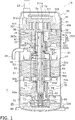
- the compressor 10 primally has a casing 20, a compression mechanism 30, an electric motor 50, a driveshaft 60, a lower housing 70, and an oil pump 80.
- An in-shaft oil supply passage 63 to supply oil O (refrigerating machine oil) to a sliding part of the compressor 10, and an in-shaft oil discharge passage 64 are formed in the driveshaft 60 (see Figure 1 ).
- the in-shaft oil discharge passage 64 constitutes a part of an oil discharge passage 90 for discharging oil O from a crank chamber 35 and an oil-recovery space 334, described later (see Figure 1 ).
- the compressor 10 has a vertically long cylindrical-shape casing 20.
- the casing 20 has a cylinder member 21 having a cylindrical shape which opens above and below, and an upper lid 22a and a lower lid 22b arranged at the upper end and the lower end respectively of the cylinder member 21.
- the cylinder member 21, and the upper lid 22a and the lower lid 22b are fixed by welding so as to keep airtightness.
- the casing 20 accommodates the constituent equipment of a compressor 10, including a compression mechanism 30, an electric motor 50, a driveshaft 60, a lower housing 70, and an oil pump 80.
- an oil retention space 25 is formed at the bottom part of the casing 20. Oil O for lubricating the driveshaft 60 and a sliding part of the compression mechanism 30 is collected in the oil retention space 25.
- an intake tube 23 that takes in refrigerant, which is to be compressed by the compression mechanism 30, is provided in the upper part of the casing 20, passing through the upper lid 22a.
- the lower end of the intake tube 23 is connected to a fixed scroll 31 of the compression mechanism 30, described later.
- the intake tube 23 communicates with a compression chamber Sc of the compression mechanism 30, described later. Low-pressure refrigerant in the refrigerant circuit is supplied to the compression chamber Sc via the intake tube 23.
- the discharge tube 24 is disposed such that the end of the discharge tube 24 on the inside of the casing 20 protrudes between the upper housing 33 of the compression mechanism 30 and the electric motor 50, described later. High-pressure refrigerant in the refrigerant circuit, compressed by the compression mechanism 30, is discharged from the discharge tube 24.
- the compression mechanism 30 is driven by the electric motor 50 and compresses the refrigerant.
- the compression mechanism 30 is disposed in the upper part in the casing 20 (see Figure 1 ).
- the compression mechanism 30 primally has a fixed scroll 31, a movable scroll 32, an upper housing 33, and an Oldham coupling 34.
- the fixed scroll 31 is disposed above the upper housing 33.
- the movable scroll 32 is coupled with the fixed scroll 31 to form a compression chamber Sc.
- the upper housing 33 forms a crank chamber 35 in which a pin bearing 323 of the movable scroll 32 described later is disposed.
- the upper housing 33 has an upper bearing 332 that pivotally supports the driveshaft 60 below the crank chamber 35 (see Figure 1 ).
- the upper housing 33 has an upper shaft seal part 333 below the upper bearing 332 (see Figure 1 ).
- the Oldham coupling 34 prevents rotation of the movable scroll 32.
- the fixed scroll 31 primally has a fixed-side plate 311, a fixed-side lap 312, and a peripheral part 313.
- the fixed-side lap 312 and the peripheral part 313 protrude downward from a surface of the fixed-side plate 311 on the movable scroll 32 side, or in other words, from the lower surface of the fixed-side plate 311.
- the fixed-side lap 312 is formed in a spiral shape.
- the fixed-side plate 311 is formed in a disc shape.
- the fixed-side lap 312 and a movable-side lap 322 of the movable scroll 32, described later, are coupled such that the lower surface of the fixed-side plate 311 and the upper surface of a movable-side plate 321 of the movable scroll 32, described later, are opposed, and the compression chamber Sc in which refrigerant is compressed is formed between the fixed scroll 31 and the movable scroll 32 (see Figure 1 ).
- a discharge outlet 311 a and discharge space 311b are formed in the fixed-side plate 311 (see Figure 1 ).
- the discharge outlet 311a is formed passing through the center part of the fixed-side plate 311 in the thickness direction of the fixed-side plate 311 (see Figure 1 ).
- the discharge outlet 311a communicates between the compression chamber Sc and the discharge space 311b (see Figure 1 ).
- the discharge space 311b communicates with a space in the casing 20 below the upper housing 33 via a refrigerant passage (not shown) formed in the fixed scroll 31 and upper housing 33.
- Refrigerant that has been compressed in the compression chamber Sc of the compression mechanism 30 passes through the refrigerant passage (not shown) and flows into the space below the upper housing 33.
- the space below the upper housing 33 is filled with high-pressure refrigerant that has been compressed by the compression mechanism 30.
- the peripheral part 313 is formed in a thick ring shape, and is disposed so as to surround the fixed-side lap 312 (see Figure 1 ).
- the movable scroll 32 which is one example of a movable part, is connected to the driveshaft 60.
- the movable scroll 32 is driven by the electric motor 50, which is connected to the driveshaft 60.
- the movable scroll 32 primally has a movable-side plate 321, a movable-side lap 322, and a pin bearing 323.
- the movable-side plate 321 is formed in a disc shape.
- the movable-side lap 322 protrudes upward from a surface of the movable-side plate 321 on the fixed scroll 31 side, or in other words, from the upper surface of the movable-side plate 321 (see Figure 1 ).
- the movable-side lap 322 is formed in a spiral shape.
- the pin bearing 323 protrudes downward from a surface of the movable-side plate 321 on the electric motor 50 side, or in other words, from the lower surface of the movable-side plate 321 (see Figure 1 ).
- the pin bearing 323 is formed in a cylindrical shape, and the upper-end opening of the cylinder is blocked by the movable-side plate 321.
- the pin bearing 323 is accommodated in the crank chamber 35, described later, which is formed by the upper housing 33.
- the movable scroll 32 and driveshaft 60 are connected by inserting a pin shaft 61 of the driveshaft 60, described later, into the pin bearing 323.
- a bearing metal 323a is fitted into the pin bearing 323.
- the pin shaft 61 inserted into the pin bearing 323 is rotatably supported by the bearing metal 323a.
- the driveshaft 60 connected to the electric motor 50 rotates, and the movable scroll 32 is driven, when the electric motor 50 is operated.
- An oil communication chamber 36 is formed in the cylindrical-shape pin bearing 323, between the upper-end surface of the pin shaft 61 of the driveshaft 60 that is inserted into the pin bearing 323 and the lower surface of the movable-side plate 321 (see Figure 1 ).
- the oil communication chamber 36 communicates with the in-shaft oil supply passage 63 which is formed in the driveshaft 60.
- the oil communication chamber 36 receives a supply of oil O from the in-shaft oil supply passage 63.
- a pin shaft channel (not shown) that extends in the vertical direction is formed between the pin shaft 61 and the bearing metal 323a.
- the upper end of the pin shaft channel opens into the oil communication chamber 36, and the lower end opens into the crank chamber 35.
- Oil O from the oil communication chamber 36 flows into the pin shaft channel.
- Oil O that has flowed into the pin shaft channel is supplied to the sliding part between the pin shaft 61 and the bearing metal 323a. After being supplied to the sliding part between the pin shaft 61 and the bearing metal 323a, the oil O flows into the crank chamber 35 formed by the upper housing 33.
- An oil passage 321a is formed in the movable-side plate 321.
- the oil passage 321a extends from an opening on the lower surface of the movable-side plate 321 that communicates with the oil communication chamber 36 radially outwardly in the disc-shape movable-side plate 321, further extends upward, and opens on the upper surface of the movable-side plate 321.
- the upper housing 33 is a cylinder-shape member that extends vertically.
- the upper housing 33 is press-fitted into the cylinder member 21, and the outer peripheral surface thereof is joined with the inner surface of the cylinder member 21 along the entirety in the circumferential direction (see Figure 1 ).
- the fixed scroll 31 is fixed to the upper housing 33 in a state in which the lower surface of the peripheral part 313 of the fixed scroll 31 and the upper-end surface of the upper housing 33 are opposed (see Figure 1 ).
- the driveshaft 60 is inserted into the cylinder-shaped upper housing 33 (see Figure 1 ).
- a recess 331 is formed in the center of the upper surface of the upper housing 33 so as to dent downward.
- the upper housing 33 has an upper bearing 332 disposed below the recess 331 and an upper shaft seal part 333 disposed below the upper bearing 332.
- the recess 331 forms a crank chamber 35 in which the pin bearing 323 of the movable scroll 32 is disposed (see Figure 1 ).
- the crank chamber 35 accommodates the pin bearing 323 of the movable scroll 32, into which the pin shaft 61 of the driveshaft 60 is inserted (see Figure 1 ).
- the crank chamber 35 communicates with a first inflow passage 67 of the in-shaft oil discharge passage 64, described later, formed in the driveshaft 60. Oil O that flows into the crank chamber 35 is discharged to the oil retention space 25 in the lower part of the casing 20 via the in-shaft oil discharge passage 64. Discharge of oil O from the crank chamber 35 is described later.
- the upper bearing 332 is one example of a bearing.
- the upper bearing 332 is disposed below the crank chamber 35 (see Figure 1 ).
- Bearing metal 332a is arranged in the upper bearing 332 (see Figure 1 ).
- the bearing metal 332a pivotally supports the main shaft 62 of the driveshaft 60, which is inserted into the upper bearing 332 of the upper housing 33.
- an upper bearing oil discharge passage 332b extending in the vertical direction (see Figure 1 ) is formed.
- the lower end of the upper bearing oil discharge passage 332b communicates with the oil-recovery space 334 disposed below the upper bearing 332 (see Figure 1 ).
- the oil-recovery space 334 is described later.
- the upper end of the upper bearing oil discharge passage 332b communicates with the crank chamber 35 disposed above the upper bearing 332.
- the upper bearing oil discharge passage 332b is a passage that leads a part of the oil O that has been supplied to the sliding part between the bearing metal 332a of the upper bearing 332 and the main shaft 62 of the driveshaft 60 to the crank chamber 35.
- the oil O that has been supplied to the sliding part between the bearing metal 332a of the upper bearing 332 and the main shaft 62 of the driveshaft 60 the oil O that does not flow into the crank chamber 35 flows into the oil-recovery space 334.
- the upper shaft seal part 333 is disposed below the upper bearing 332 (see Figure 1 ).
- the upper shaft seal part 333 is formed in a cylindrical shape.
- the inside diameter of the upper shaft seal part 333 is substantially equal to the outside diameter of the main shaft 62 of the driveshaft 60, which is disposed within the upper shaft seal part 333.
- the inside diameter of the upper shaft seal part 333 is slightly larger than the outside diameter of the main shaft 62 of the driveshaft 60, which is disposed within the upper shaft seal part 333.
- the upper shaft seal part 333 prevents leakage of oil O from the lower part of the gap between the upper housing 33 and the driveshaft 60.
- An annular space is formed between the upper bearing 332 and the upper shaft seal part 333, and between the upper housing 33 and the driveshaft 60, so as to surround the driveshaft 60.
- the annular space may be formed between the main shaft 62 and the upper housing 33 by reducing the outside diameter of the main shaft 62 of the driveshaft 60, or may be formed between the main shaft 62 and the upper housing 33 by increasing the inside diameter of the upper housing 33.
- This space functions as an oil-recovery space 334 (see Figure 1 ).
- the oil-recovery space 334 is formed in the lower part of the upper housing 33.
- the oil-recovery space 334 communicates with a second inflow passage 64b, described later, of the in-shaft oil discharge passage 64 formed in the driveshaft 60.
- Oil O that has flowed into the oil-recovery space 334 is discharged into the oil retention space 25 in the lower part of the casing 20, via the in-shaft oil discharge passage 64. Discharge of oil O from the oil-recovery space 334 is described later.
- An upper shaft seal ring 41 is disposed at the upper shaft seal part 333 (see Figure 1 ). By disposing the upper shaft seal ring 41 at the upper shaft seal part 333, leakage of oil O from the lower part of the upper housing 33 is prevented even if the pressure in the crank chamber 35 rises, and oil loss can be suppressed.
- the upper shaft seal ring 41 is disposed at the lower part of the upper shaft seal part 333 and between the upper shaft seal part 333 and the driveshaft 60 (see Figure 1 ).
- the upper shaft seal ring 41 is disposed in an annular seal ring groove 41a, which is formed on the main shaft 62 of the driveshaft 60 at a region that opposes the upper shaft seal part 333 (see Figure 1 ).
- the upper shaft seal ring 41 may be disposed in an annular seal ring groove formed on the upper shaft seal part 333 instead of being disposed in a seal ring groove 41a formed in the main shaft 62 of the driveshaft 60.
- the upper shaft seal ring 41 is made of metal or of resin.
- a metal material with good high-temperature characteristics, or a resin material is used in the upper shaft seal ring 41.
- the upper shaft seal ring 41 is formed in an annular shape, and has an abutment (a cut portion), not shown.
- the shape of the abutment is for example an angle-cut shape.
- the invention is not limited thereto; the shape of the abutment may be, for example, a step-cut shape or the like. The shape of the abutment may be determined appropriately.
- the value of the ratio of the axial-direction height h1 of the upper shaft seal ring 41 (see Figure 1 ) to the diameter A1 of the main shaft 62 of the driveshaft 60 at a portion where the upper shaft seal ring 41 is installed is 0.047, but such an arrangement is not provided by way of limitation.
- the value of the ratio of the axial-direction height h1 of the upper shaft seal ring 41 to the diameter A1 of the main shaft 62 of the driveshaft 60 at a portion where the upper shaft seal ring 41 is installed be 0.04 or greater and less than 0.07.
- the value of the ratio of the radial-direction thickness w1 of the upper shaft seal ring 41 (see Figure 1 ) to the diameter A1 of the main shaft 62 of the driveshaft 60 at a portion where the upper shaft seal ring 41 is installed is 0.040, but such an arrangement is not provided by way of limitation. In order to obtain sufficient seal properties, it is preferable that the value of the ratio of the radial-direction thickness w1 of the upper shaft seal ring 41 to the diameter A1 of the main shaft 62 of the portion of the driveshaft 60 at a portion where the upper shaft seal ring 41 is installed be 0.03 or greater and less than 0.06.
- the Oldham coupling 34 is provided at the upper surface of the upper housing 33 (see Figure 1 ).
- the Oldham coupling 34 is slidably fitted into the movable-side plate 321 of the movable scroll 32 and the upper housing 33.
- the Oldham coupling 34 prevents rotation of the movable scroll 32, which is driven by the electric motor 50. Through the action of the Oldham coupling 34, the movable scroll 32 revolves relative to the fixed scroll 31 without rotating.
- the electric motor 50 is disposed below the upper housing 33 of the compression mechanism 30 (see Figure 1 ).
- the electric motor 50 has a stator 51 that is fixed to an inner-wall surface of the cylinder member 21, and a rotor 53 that is rotatably accommodated on the inside of the stator 51 with a slight gap (air gap) provided (see Figure 1 ).
- the stator 51 has a tube-shape stator core 52 and windings (not shown) that are wound around the stator core 52.
- a core cut 52a extending in the vertical direction, is formed in the outer peripheral surface of the stator core 52 (see Figure 1 ). At the portion of the core cut 52a, a gap is formed between the stator core 52 and the cylinder member 21 of the casing 20.
- the core cut In a compressor of a type that differs from the present compressor 10 in that oil that collects in the crank chamber is returned to the oil retention space via the gap at a core cut portion, the core cut needs to be formed to be large. In contrast, in the present compressor 10, since an in-shaft oil discharge passage 64 to return oil O in the crank chamber 35 to the oil retention space 25 is formed in the driveshaft 60, the core cut 52a can be comparatively small. Accordingly, compared with a compressor of the type that returns oil that collects in the crank chamber to the oil retention space via the gap at the core cut portion, the motor efficiency of the compressor 10 can be improved.
- the rotor 53 is formed in a tube shape. By inserting the driveshaft 60 into the rotor 53, the rotor 53 and the driveshaft 60 are connected.
- the driveshaft 60 is also connected to the movable scroll 32. That is, the rotor 53 is connected to the movable scroll 32 via the driveshaft 60.
- the electric motor 50 drives the movable scroll 32 by causing the rotor 53 to rotate.
- the driveshaft 60 extends in the vertical direction along the axial center of the cylinder member 21 of the casing 20 (see Figure 1 ).
- the driveshaft 60 is connected to the rotor 53 of the electric motor 50, and transmits the driving power of the electric motor 50 to the movable scroll 32.
- the driveshaft 60 has a main shaft 62, the center axis of which coincides with the axial center of the cylinder member 21, and a pin shaft 61 that is eccentric relative to the main shaft 62 (see Figure 1 ).
- the pin shaft 61 is one example of an eccentric part.
- the pin shaft 61 is formed to have a smaller diameter than the main shaft 62. As stated above, the pin shaft 61 is inserted into the pin bearing 323 of the movable scroll 32. The pin shaft 61 is rotatably supported by the bearing metal 323a that is disposed within the pin bearing 323.
- the main shaft 62 is rotatably supported by the bearing metal 332a of the upper bearing 332 of the upper housing 33 and by a bearing metal 71a of a lower bearing 71 of the lower housing 70, described later (see Figure 1 ).
- the main shaft 62 is connected to the rotor 53 of the electric motor 50 between the upper bearing 332 and the lower bearing 71 (see Figure 1 ).
- the driveshaft 60 rotates about a rotation center C (see Figure 2 and Figure 4 ).
- the rotation center C is the center position of the main shaft 62 in plan view.
- the main shaft 62 (driveshaft 60) rotates counterclockwise in plan view (see the rotation direction K in Figure 4 ).
- the in-shaft oil supply passage 63 to supply oil O to the sliding part of the compressor 10 is formed, as indicated in Figure 1 .
- the in-shaft oil discharge passage 64 communicating the crank chamber 35 and the oil-recovery space 334 is formed in the driveshaft 60 to discharge oil O that has collected in the crank chamber 35 and the oil-recovery space 334.
- the in-shaft oil supply passage 63 and in-shaft oil discharge passage 64 are described later.
- An oil pump shaft receiver 69 is fixed to the lower end of the main shaft 62 of the driveshaft 60 (see Figure 1 ). Specifically, the oil pump shaft receiver 69 is inserted into and secured in an opening of an inflow passage 63a of the in-shaft oil supply passage 63, described later, that is formed at the lower end of the main shaft 62.
- the oil pump shaft receiver 69 is a hollow member.
- An oil pump shaft 84 of the oil pump 80 is inserted into the hollow part of the oil pump shaft receiver 69 from the lower-end side, as described later (see Figure 9 ).
- an axial-direction joint passage 84b is formed in the oil pump shaft 84 (see Figure 9 ).
- the axial-direction joint passage 84b communicates with the inflow passage 63a of the in-shaft oil supply passage 63, into which the oil pump shaft receiver 69 is inserted (see Figure 9 ).
- the lower housing 70 is disposed in the lower part in the casing 20 (see Figure 1 ).
- the lower housing 70 is disposed below the electric motor 50.
- the lower housing 70 is a cylinder-shape member that extends vertically. A part of the outer peripheral surface of the lower housing 70 protrudes toward the cylinder member 21 of the casing 20 (see Figure 10 ) and is fixed to the cylinder member 21.
- the driveshaft 60 is inserted into the cylinder-shape lower housing 70 (see Figure 1 ).
- the upper part of the lower housing 70 has a lower shaft seal part 77 (see Figure 1 ) on its upper part.
- the lower housing 70 has a lower bearing 71 below the lower shaft seal part 77 (see Figure 1 ).
- a recess 72 that dents upward is formed (see Figure 1 ).
- the oil pump 80 is fixed to the lower-end surface of the lower housing 70 so as to block the lower opening of the recess 72 (see Figure 1 ).
- the lower bearing 71 pivotally supports the driveshaft 60.
- a bearing metal 71a is arranged in the lower bearing 71 (see Figure 1 ).
- the bearing metal 71a pivotally supports the main shaft 62 of the driveshaft 60 disposed in the lower bearing 71 of the lower housing 70.
- the lower shaft seal part 77 is formed in a cylinder shape.
- the inside diameter of the lower shaft seal part 77 is substantially equal to the outside diameter of the main shaft 62 of the driveshaft 60, which is disposed in the lower shaft seal part 77.
- the inside diameter of the lower shaft seal part 77 is slightly larger than the outside diameter of the main shaft 62 of the driveshaft 60, which is disposed in the lower shaft seal part 77.
- the lower shaft seal part 77 prevents leakage of oil O from the upper part of the gap between the lower housing 70 and the driveshaft 60.
- annular space is formed between the lower bearing 71 and the lower shaft seal part 77 and between the lower housing 70 and the driveshaft 60, so as to surround the driveshaft 60 (see Figure 9 ).
- the annular space may be formed between the main shaft 62 and the lower housing 70 by reducing the outside diameter of a part of the main shaft 62 of the driveshaft 60, or may be formed between the main shaft 62 and the lower shaft seal part 77 by reducing the inside diameter of a part of the lower housing 70.
- This space functions as an annular space 76 (see Figure 1 ).
- the annular space 76 is a space that is adjacent to the bearing metal 71a of the lower bearing 71 (see Figure 9 ).
- the annular space 76 communicates with a main oil discharge passage 64c of the in-shaft oil discharge passage 64, described later, via an outflow passage 64d of the in-shaft oil discharge passage 64, described later (see Figure 9 ).
- Oil O that has flowed through the main oil discharge passage 64c and the outflow passage 64d flows into the annular space 76.
- a part of the oil O that has been supplied to the sliding part between the bearing metal 71a of the lower bearing 71 and the main shaft 62 of the driveshaft 60 flows into the annular space 76.
- the annular space 76 communicates with an in-lower-housing oil discharge passage 74 formed in the lower housing 70.
- the in-lower-housing oil discharge passage 74 is one example of an oil passage.
- the in-lower-housing oil discharge passage 74 communicates with a lower space 78 that is surrounded by the recess 72 of the lower housing 70 and the oil pump 80 (see Figure 9 ).
- Oil O that flows into the annular space 76 passes through the in-lower-housing oil discharge passage 74 and flows into the lower space 78. Further, a part of the oil O that has been supplied to the sliding part between the bearing metal 71a of the lower bearing 71 and the main shaft 62 of the driveshaft 60 flows directly (without passing through the in-lower-housing oil discharge passage 74) into the lower space 78.
- Oil O that has flowed into the lower space 78 is led to the oil discharge pump part 80B of the oil pump 80, described later, and flows into the oil retention space 25. That is, the in-lower-housing oil discharge passage 74 communicate between the annular space 76 and the oil retention space 25 via the lower space 78 and the oil discharge pump part 80B.
- a lower shaft seal ring 42 is arranged at the lower shaft seal part 77. Because the lower shaft seal ring 42 is arranged at the lower shaft seal part 77, leakage of oil O from the upper part of the lower housing 70 can be prevented, and oil loss can be suppressed.
- the lower shaft seal ring 42 is disposed between the lower shaft seal part 77 and the driveshaft 60, at the upper part of the lower shaft seal part 77 (see Figure 9 ).
- the lower shaft seal ring 42 is disposed in an annular seal ring groove 42a, which is formed on the main shaft 62 of the driveshaft 60 at a region that opposes the lower shaft seal part 77 (see Figure 9 ).
- the lower shaft seal ring 42 may be disposed in an annular seal ring groove formed on the lower shaft seal part 77 instead of being disposed in a seal ring groove 42a formed in the main shaft 62 of the driveshaft 60.
- the lower shaft seal ring 42 is made of metal or of resin.
- a metal material with good high-temperature characteristics, or a resin material is used in the lower shaft seal ring 42.
- the lower shaft seal ring 42 is formed in an annular shape, and has an abutment (a cut portion), not shown.
- the shape of the abutment is, for example, an angle-cut shape.
- the invention is not limited thereto; the shape of the abutment may be, for example, a step-cut shape or the like. The shape of the abutment may be determined appropriately.
- the value of the ratio of the axial-direction height h2 of the lower shaft seal ring 42 (see Figure 9 ) to the diameter A2 of the main shaft 62 of the driveshaft 60 at a position where the lower shaft seal ring 42 is installed is 0.053, but such an arrangement is not provided by way of limitation.
- the value of the ratio of the axial-direction height h2 of the lower shaft seal ring 42 to the diameter A2 of the main shaft 62 of the driveshaft 60 at a portion where the lower shaft seal ring 42 is installed be 0.04 or greater and less than 0.07.
- the value of the ratio of the radial-direction thickness w2 of the lower shaft seal ring 42 (see Figure 9 ) to the diameter A2 of the main shaft 62 of the driveshaft 60 at a portion where the lower shaft seal ring 42 is installed is 0.045, but such an arrangement is not provided by way of limitation. In order to obtain sufficient seal properties, it is preferable that the value of the ratio of the radial-direction thickness w2 of the lower shaft seal ring 42 to the diameter A2 of the main shaft 62 of the driveshaft 60 at a portion where the lower shaft seal ring 42 is installed be 0.03 or greater and less than 0.06.
- the in-shaft oil supply passage 63 is one example of an oil supply passage.
- the in-shaft oil supply passage 63 is an oil passage to supply oil O in the oil retention space 25, supplied by the oil supply pump part 80A of the oil pump 80, described later, to each of the sliding parts of the compressor 10.
- the in-shaft oil supply passage 63 is formed in the driveshaft 60 (see Figure 1 ).
- the in-shaft oil supply passage 63 transports oil O in the oil retention space 25 to the upper end of the pin shaft 61 of the driveshaft 60, which is disposed in the crank chamber 35. In other words, the in-shaft oil supply passage 63 transports oil O in the oil retention space 25 to the crank chamber 35.
- the in-shaft oil supply passage 63 primally has an inflow passage 63a, a main oil supply passage 63b, an upper outflow passage 63c, and a lower outflow passage 63d.
- Figure 3 is a cross-sectional view in which the upper part of the driveshaft 60 is sectioned at the S-C-S' cross-section in Figure 2 .
- Figure 7 is a cross-sectional view in which the lower part of the driveshaft 60 is sectioned at the S-C-T cross-section in Figure 2 .
- C indicates the rotation center C of the driveshaft 60.
- the inflow passage 63a is a recess that opens in the lower end of the driveshaft 60 (see Figure 7 ).
- the inflow passage 63a is formed so as to dent upward from the lower end in the center part of the driveshaft 60 (see Figure 7 ).
- the oil pump shaft receiver 69 is inserted from the lower-end opening into the inflow passage 63a. Further, the oil pump shaft 84 of the oil pump 80, described later, is inserted into the hollow oil pump shaft receiver 69.
- the inflow passage 63a communicates with the axial-direction joint passage 84b formed in the oil pump shaft 84 of the oil pump 80 (see Figure 9 ). Oil O in the oil retention space 25 is supplied from the inflow passage 63a to the in-shaft oil supply passage 63 by the oil supply pump part 80A of the oil pump 80.
- the main oil supply passage 63b extends in the axial direction, that is, in the vertical direction, in the driveshaft 60.
- the lower end of the main oil supply passage 63b communicates with the inflow passage 63a.
- the upper end of the main oil supply passage 63b opens at the upper-end surface of the pin shaft 61 of the driveshaft 60.
- the main oil supply passage 63b communicates with the oil communication chamber 36.
- the upper outflow passage 63c extends in the driveshaft 60 from the main oil supply passage 63b in a direction intersecting the axial direction.
- the upper outflow passage 63c extends in the driveshaft 60 from the main oil supply passage 63b in a direction perpendicular to the axial direction (see Figure 3 ).
- the upper outflow passage 63c extends in the driveshaft 60 from the main oil supply passage 63b in the radial direction (see Figure 2 ).
- the upper outflow passage 63c opens at the outer peripheral surface of the driveshaft 60 at the upper bearing 332 of the upper housing 33. Oil O that flows out from the opening of the upper outflow passage 63c on the outer peripheral surface of the driveshaft 60 is supplied to the sliding part between the bearing metal 332a of the upper bearing 332 and the main shaft 62 of the driveshaft 60.
- the lower outflow passage 63d extends in the driveshaft 60 from the main oil supply passage 63b in a direction intersecting the axial direction (see Figure 7 ).
- the lower outflow passage 63d extends in the driveshaft 60 from the main oil supply passage 63b in a direction perpendicular to the axial direction (see Figure 7 ).
- the lower outflow passage 63d extends in the driveshaft 60 from the main oil supply passage 63b in the radial direction (see Figure 2 ).
- the lower outflow passage 63d opens at the outer peripheral surface of the driveshaft 60 at the lower bearing 71 of the lower housing 70. Oil O that flows out from the opening of the lower outflow passage 63d on the outer peripheral surface of the driveshaft 60 is supplied to the sliding part between the bearing metal 71a of the lower bearing 71 and the main shaft 62 of the driveshaft 60.
- the opening of the upper outflow passage 63c on the outer peripheral surface of the driveshaft 60 and the opening of the lower outflow passage 63d on the outer peripheral surface of the driveshaft 60 are disposed approximately 180° away relative to the rotation center C of the driveshaft 60 (see Figure 2 ).
- the upper outflow passage 63c and the lower outflow passage 63d extend substantially on a straight line that passes through the rotation center C of the driveshaft 60.
- the upper outflow passage 63c and the lower outflow passage 63d substantially extend on the straight line S-T extending to pass through the rotation center C of the driveshaft 60.
- the mode in which the upper bearing 332 and the lower bearing 71 receive a load is a "rotating load," where the magnitudes of load are substantially constant, but the load directions fluctuate in synchronization with the shaft rotation. Accordingly, if openings of outflow passages are respectively designed to be arranged on opposite sides of the direction in which the load is supported (substantially at the angles of the positions of minimum oil film thickness) at the upper bearing 332 and the lower bearing 71, the flow of oil O supplied to the upper bearing 332 and the lower bearing 71 can be maximally increased.
- a dedicated lower bearing passage (vertical hole) 63e extending in the axial direction from the inflow passage 63a and being separate from the main oil supply passage 63b, may be provided at the position that is axially symmetric with the main oil supply passage 63b relative to the rotation center C of the driveshaft 60, as indicated in Figure 8 .
- the lower outflow passage 63d may be communicated with the dedicated lower bearing passage 63e and not with the main oil supply passage 63b, so that oil O is supplied to the lower outflow passage 63d via the dedicated lower bearing passage 63e.
- the oil discharge passage 90 is an oil passage that leads oil O in the crank chamber 35 and the oil-recovery space 334, and oil O that has been supplied to the lower bearing 71, to the oil discharge pump part 80B of the oil pump 80.
- the oil discharge passage 90 primally includes the in-shaft oil discharge passage 64, the annular space 76, the in-lower-housing oil discharge passage 74, and the lower space 78 surrounded by the recess 72 of the lower housing 70 and the oil pump 80 (see Figure 1 ).
- the in-shaft oil discharge passage 64 leads the oil O in the crank chamber 35 and the oil-recovery space 334 to the annular space 76 formed around the main shaft 62 of the driveshaft 60.
- the oil O in the annular space 76 is transported to the lower space 78 through the in-lower-housing oil discharge passage 74.
- the oil O that has collected in the crank chamber 35 includes oil O that has been supplied to the sliding part between the pin shaft 61 of the driveshaft 60 and the bearing metal 323a of the first pin bearing 323.
- the oil O that collects in the crank chamber 35 includes oil O that, after being supplied to the sliding part between the main shaft 62 of the driveshaft 60 and the bearing metal 332a of the upper bearing 332, passes through the upper bearing oil discharge passage 332b and flows into the crank chamber 35.
- the oil O that flows into the oil-recovery space 334 includes oil O that has been supplied to the sliding part between the main shaft 62 of the driveshaft 60 and the bearing metal 332a of the upper bearing 332.
- the oil O that flows into the annular space 76 includes oil O that has flowed from the in-shaft oil discharge passage 64, and a part of the oil O that has been supplied to the sliding part between the main shaft 62 of the driveshaft 60 and the bearing metal 71 a of the lower bearing 71.
- the in-shaft oil discharge passage 64 primally has the first inflow passage 67, the second inflow passage 64b, the main oil discharge passage 64c, and the outflow passage 64d (see Figure 1 ).
- the first inflow passage 67 communicates between the main oil discharge passage 64c and the crank chamber 35 (see Figure 1 ).
- the first inflow passage 67 is formed in a base of the pin shaft 61 (see Figure 3 , Figure 5 and Figure 6 ).
- the pin shaft 61 of the driveshaft 60 is disposed in the crank chamber 35 formed by the upper housing 33, but in the present embodiment, the space in the in-shaft oil discharge passage 64 (the space within the pin shaft 61) is defined as a space that is different from the crank chamber 35.
- the space in the first inflow passage 67 and the main oil discharge passage 64c, which is formed in the inside of the outer peripheral edge of the pin shaft 61, is defined as the space that is different from the crank chamber 35.
- the main oil discharge passage 64c is a hole that extends in the driveshaft 60 in the axial direction, that is, in the vertical direction.
- the main oil discharge passage 64c is formed to be circular in plan view.
- the main oil discharge passage 64c extends from the upper end surface of the pin shaft 61 of the driveshaft 60 to the lower part of the driveshaft 60.
- the opening of the main oil discharge passage 64c at the upper end is closed by a plug 64e (see Figure 1 ). Accordingly, the main oil discharge passage 64c does not communicate with the oil communication chamber 36 formed above the pin shaft 61.
- the first inflow passage 67 primally has an intake hole 65 and an introduction part 66 (see Figure 3 and Figure 4 ).
- the intake hole 65 is one example of an outlet-vicinity part.
- the intake hole 65 is a hole that opens into the main oil discharge passage 64c.
- the opening of the intake hole 65 into the main oil discharge passage 64c is referred to as an inflow passage outlet 67b (see Figures 4-6 ). That is, the intake hole 65 is arranged near the inflow passage outlet 67b, and more precisely, adjacent to the inflow passage outlet 67b.
- the inflow passage outlet 67b is an opening formed in the outer peripheral edge of the main oil discharge passage 64c.
- the inflow passage outlet 67b is an opening that, in a case that the main oil discharge passage 64c were supposed to be a solid column member, would be formed on the outer peripheral surface of the column member by opening the intake hole 65.
- the inflow passage outlet 67b is disposed on the outer peripheral edge of the main oil discharge passage 64c, in the interval indicated by the double-headed arrow in Figure 4 .
- the intake hole 65 extends in a straight line from the main oil discharge passage 64c, or in other words, from the inflow passage outlet 67b. Seen in a side view (seen from a direction perpendicular to the axial direction of the driveshaft 60), the intake hole 65 is a hole formed in a circular shape (see Figure 6 ). Accordingly, the inflow passage outlet 67b is also formed to be circular in a side view (see Figure 6 ).
- the intake hole 65 extends in a straight line that intersects the axial direction of the driveshaft 60.
- the intake hole 65 extends along a straight line that is perpendicular to the axial direction of the driveshaft 60.
- the intake hole 65 extends along a straight line L that passes through the rotation center C of the driveshaft 60 (the center of the main shaft 62) and the centroid Z2 of the inflow passage outlet 67b, and is perpendicular to the axial direction of the driveshaft 60 (see Figure 3 ).
- the centroid Z2 of the inflow passage outlet 67b in plan view means the centroid of an imagined figure, which is an imagined figure of small width extending along the outer peripheral edge of the main oil discharge passage 64c in the interval of the outer peripheral edge of the main oil discharge passage 64c in which the inflow passage outlet 67b is disposed (the interval of the outer peripheral edge of the main oil discharge passage 64c indicated by the double-headed arrow in Figure 4 ).
- the intake hole 65 has a pair of straight parts 65a extending in straight lines from the inflow passage outlet 67b (see Figure 4 ). Both straight parts 65a extend from the inflow passage outlet 67b parallel to a straight line L toward the outside of the pin shaft 61 (see the direction of the arrow B in Figure 4 ).
- the introduction part 66 is formed in the base of the pin shaft 61 so as to core out the interior of the pin shaft 61 from the outer peripheral surface of the pin shaft 61 (see Figure 5 ).
- the introduction part 66 is the space surrounded by the outer peripheral edge of the pin shaft 61 (the interval which is formed on the inflow passage inlet 67a, described later, and is indicated by the double-headed arrow in Figure 4 ), a first surface 66a that extends continuously from one of the straight parts 65a of the intake hole 65, a second surface 66b that extends in a direction perpendicular to the straight line L, and the intake hole 65.
- the introduction part 66 is formed so as to extend longer in a direction perpendicular to the straight line L (a direction in which the second surface 66b extends) than the direction of the straight line L (a direction in which the first surface 66a extends).
- the introduction part 66 is a space that communicates with the intake hole 65 (see Figure 3 and Figure 4 ). Further, the introduction part 66 is a space that communicates with the crank chamber 35 (see Figure 3 and Figure 4 ). In other words, the introduction part 66 opens into the crank chamber 35.
- the opening of the introduction part 66 into the crank chamber 35 is referred to as the inflow passage inlet 67a (see Figures 4-6 ).
- the inflow passage inlet 67a is an opening formed in the outer peripheral edge of the pin shaft 61 (see Figure 5 ). In plan view, the inflow passage inlet 67a is disposed in the interval on the outer peripheral edge of the pin shaft 61 indicated by the double-headed arrow in Figure 4 .
- the inflow passage inlet 67a is formed in a rectangular shape that extends longer in the horizontal direction (see Figure 6 ).
- the oil O in the crank chamber 35 flows into the introduction part 66 through the inflow passage inlet 67a.
- the inflow passage inlet 67a which is the inlet for oil O from the crank chamber 35 into the first inflow passage 67 (the inflow passage inlet 67a that opens into the crank chamber 35)
- the inflow passage outlet 67b which is the outlet for oil O from the first inflow passage 67 to the main oil discharge passage 64c (the inflow passage outlet 67b that opens into the main oil discharge passage 64c).
- the inflow passage inlet 67a is configured to have an area larger than the area of the inflow passage outlet 67b as indicated in 1) above, oil O in the crank chamber 35 is readily guided to the main oil discharge passage 64c by the first inflow passage 67 compared with a case in which the area of the inflow passage inlet 67a is not larger than the area of the inflow passage outlet 67b.
- inflow passage inlet 67a is deflected forward in the rotation direction K of the driveshaft 60 than the inflow passage outlet 67b as indicated in 2) above, when the driveshaft 60 rotates, oil O is readily guided to the introduction part 66 from the inflow passage inlet 67a, which is disposed forward side in the rotation direction K than the inflow passage outlet 67b, and oil O is readily guided to the main oil discharge passage 64c.
- the introduction part 66 has the first surface 66a that extends in a direction that intersects the rotation direction K.
- the first surface 66a is one example of a guide surface.
- the first surface 66a is a linear extension of the straight part 65a of the intake hole 65 on the rearward side in the rotation direction K of the driveshaft 60 (the straight part 65a of the intake hole 65 further on the rearward side in the rotation direction K than the straight line L) (see Figure 4 ). That is, in plan view, the introduction part 66 has a first surface 66a that extends parallel to the straight line L (see Figure 4 ).
- the intake hole 65 is formed with a drill, and thereafter the introduction part 66 is formed with an end mill.
- the formation methods of the intake hole 65 and the introduction part 66 are an example, and the invention is not limited thereto.
- Various machining methods can be applied as formation methods of the intake hole 65 and the introduction part 66.
- the second inflow passage 64b communicates between the main oil discharge passage 64c and the oil-recovery space 334.
- the second inflow passage 64b extends in the driveshaft 60 from the main oil discharge passage 64c in a direction that intersects with the axial direction.
- the second inflow passage 64b extends in the driveshaft 60 in a direction perpendicular to the axial direction.
- the second inflow passage 64b extends in the driveshaft 60 in a radial direction from the main oil discharge passage 64c.
- the second inflow passage 64b is formed in a position at the height of the oil-recovery space 334 of the upper housing 33.
- the second inflow passage 64b opens on the outer peripheral surface of the driveshaft 60 in the oil-recovery space 334 formed above the upper shaft seal part 333.
- One end of the second inflow passage 64b communicates with the oil-recovery space 334, and the other end communicates with the main oil discharge passage 64c.
- Oil O in the oil-recovery space 334 flows into the in-shaft oil discharge passage 64 from the opening of the second inflow passage 64b.
- the outflow passage 64d extends in the driveshaft 60 from the lower end of the main oil discharge passage 64c in a direction that intersects the axial direction.
- the outflow passage 64d extends in the driveshaft 60 from the lower end of the main oil discharge passage 64c in a direction perpendicular to the axial direction.
- the outflow passage 64d extends in the driveshaft 60 from the lower end of the main oil discharge passage 64c in a radial direction.
- the outflow passage 64d opens on the outer peripheral surface of the main shaft 62 of the driveshaft 60 in the annular space 76 formed between the lower housing 70 and the main shaft 62 of the driveshaft 60. That is, the outflow passage 64d communicates with the annular space 76.
- Oil O that has flowed into the annular space 76 is discharged, via the in-lower-housing oil discharge passage 74 formed in the lower housing 70, into the lower space 78 surrounded by the recess 72 of the lower housing 70 and the oil pump 80.
- the oil pump 80 is a double trochoidal positive displacement pump.
- the oil pump 80 is fastened to the lower-end surface of the lower housing 70 with bolts 83.
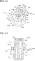
- the oil pump 80 primally has a thrust plate 73, a pump body 81, a pump cover 82, an oil pump shaft 84, a lower-side outer rotor 85, a lower-side inner rotor 86, an upper-side outer rotor 87, and an upper-side inner rotor 88.
- the oil pump 80 includes an oil supply pump part 80A that supplies oil O in the oil retention space 25 to the in-shaft oil supply passage 63, and an oil discharge pump part 80B that discharges oil O in the crank chamber 35 to the oil retention space 25 via the oil discharge passage 90 (see Figure 9 ).
- the oil supply pump part 80A is one example of an oil supply pump.
- the oil discharge pump part 80B is one example of an oil discharge pump.
- the oil supply pump part 80A includes the lower-side outer rotor 85 and the lower-side inner rotor 86 (see Figure 9 ).
- the oil discharge pump part 80B includes the upper-side outer rotor 87 and the upper-side inner rotor 88 (see Figure 9 ).
- Driving force is transmitted to the lower-side inner rotor 86 of the oil supply pump part 80A and to the upper-side inner rotor 88 of the oil discharge pump part 80B through the oil pump shaft 84.
- the oil pump shaft 84 is connected to the lower part of the driveshaft 60, and when the driveshaft 60 rotates, the oil pump shaft 84 also rotates.
- the oil supply pump part 80A functions as a displacement-type oil supply pump
- the oil discharge pump part 80B functions as a displacement-type oil discharge pump
- oil pump 80 is described in detail.
- the thrust plate 73 is formed in a disc shape (see Figure 10 ).
- the thrust plate 73 is installed in the lower housing 70 so as to block the recess 72 formed in the lower housing 70 (see Figure 9 and Figure 10 ).
- the lower-end surface of the oil pump shaft receiver 69 installed on the lower end of the driveshaft 60 is in sliding contact with the thrust plate 73 (see Figure 9 ).
- the thrust plate 73 receives the thrust force of the driveshaft 60.
- an insertion hole 73b for insertion of the lower part of the oil pump shaft 84 is formed (see Figure 9 and Figure 10 ).
- a discharge outlet 73a to guide oil O in the lower space 78 above the thrust plate 73 to the oil discharge pump part 80B is formed (see Figure 9 and Figure 10 ).
- the upper end of the discharge outlet 73a communicates with the lower space 78, and the lower end communicates with an in-body upper-side channel 81b in the pump body 81, described later.
- the pump body 81 is a substantially cylindrical shape member that extends in the vertical direction.
- the oil pump shaft 84, the lower-side outer rotor 85, the lower-side inner rotor 86, the upper-side outer rotor 87, and the upper-side inner rotor 88 are accommodated (see Figure 9 ).
- an outer peripheral edge 81a protruding upward is formed (see Figure 10 ).
- the pump body 81 is fixed to the lower housing 70 in a state in which the thrust plate 73 is fitted to the inside of the outer peripheral edge 81a (see Figure 9 ).
- an in-body upper-side channel 81b dented downward is formed (see Figure 9 and Figure 10 ).
- an in-body lower-side channel 81c dented upward is formed (see Figure 9 and Figure 10 ).
- the in-body lower-side channel 81c is formed in a circular shape in plan view.
- an inner peripheral hole 81d, into which the oil pump shaft 84 is inserted, is formed (see Figure 9 and Figure 10 ).
- a discharge channel 81e that extends in a horizontal direction and penetrates through the inside and the outside, is formed (see Figure 9 and Figure 10 ).
- One end (the end on the inside) of the discharge channel 81e opens into the in-body upper-side channel 81b, and the other end (the end on the outside) opens on the outer peripheral surface of the pump body 81 (see Figure 9 ).
- Pump outlet piping 89 is installed at the discharge channel 81e (see Figure 9 ).
- the pump outlet piping 89 is formed in an L shape.
- the pump outlet piping 89 extends in a horizontal direction along the discharge channel 81e, then changes direction by 90°, and extends downward.
- the lower end of the pump outlet piping 89 is disposed below the lower end of the oil pump 80.
- the lower end of the pump outlet piping 89 is disposed in the lower part of the oil retention space 25.
- the pump outlet piping 89 guides oil O that has flowed from the oil discharge pump part 80B via the discharge channel 81e to the lower part of the oil retention space 25.
- oil O is not discharged from the discharge channel 81e in a horizontal direction, but instead, oil O is discharged to the lower part of the oil retention space 25 through the pump outlet piping 89. Therefore, it can be prevented that mist of the oil O is transported together with refrigerant and discharged from the discharge tube 24 to the refrigerant circuit. Further, since the discharge channel 81e opens near the liquid surface in the oil retention space 25, if there were no pump outlet piping 89, oil O discharged from the discharge channel 81e would disturb the liquid surface, and there would be the concern that scattering of mist of the oil O would be promoted. In contrast, in the present embodiment, oil O is discharged to the lower part of the oil retention space 25 through the pump outlet piping 89, and therefore the liquid surface of the oil retention space 25 is not disturbed.
- the pump cover 82 is formed in substantially a disc shape (see Figure 10 ).
- the pump cover 82 is fastened to the lower surface of the pump body 81 (see Figure 9 and Figure 10 ).
- the oil pump shaft 84 is rotatably supported in the center part of the pump cover 82 (see Figure 9 and Figure 10 ). Moreover, in the pump cover 82, an arc-shape intake inlet 82a that, in plan view, is on the outside of the oil pump shaft 84 supported by the pump cover 82 is formed (see Figure 9 and Figure 10 ).
- the intake inlet 82a is formed passing through the pump cover 82 in the vertical direction.
- the lower end of the intake inlet 82a opens into the oil retention space 25.
- the upper end of the intake inlet 82a opens into the in-body lower-side channel 81c formed in the pump body 81.
- the oil pump shaft 84 is formed in a circular shape, and extends in the vertical direction (see Figure 9 ).
- the lower part of the oil pump shaft 84 is rotatably supported by the pump cover 82 (see Figure 9 and Figure 10 ).
- the oil pump shaft 84 is inserted into the inner peripheral hole 81d formed in the pump body 81, and is rotatably supported by the pump body 81 (see Figure 9 and Figure 10 ).
- the oil pump shaft 84 is inserted into the insertion hole 73b in the thrust plate 73, which is disposed in the upper part of the pump body 81 (see Figure 9 and Figure 10 ).
- the oil pump shaft 84 is inserted from below into the interior of the oil pump shaft receiver 69 installed in the inflow passage 63a formed in the lower end of the main shaft 62 of the driveshaft 60, and is fitted with the oil pump shaft receiver 69 (see Figure 9 and Figure 10 ).
- the upper end of the oil pump shaft 84 which is formed in a hexagonal shape, is inserted into a hexagonal-shape hole provided in an inside-diameter part of the oil pump shaft receiver 69. That is, the oil pump shaft 84 is connected to the lower part of the driveshaft 60 via the oil pump shaft receiver 69.
- the oil pump shaft 84 rotates integrally with the driveshaft 60.
- a radial-direction joint passage 84a and the axial-direction joint passage 84b are formed (see Figure 9 and Figure 10 ).
- the radial-direction joint passage 84a penetrates the oil pump shaft 84 in a radial direction (see Figure 9 ).
- the radial-direction joint passage 84a opens into the in-body lower-side channel 81c of the pump body 81.
- the axial-direction joint passage 84b extends in the oil pump shaft 84 in the axial direction (in the vertical direction).
- the axial-direction joint passage 84b opens in the upper-end surface of the oil pump shaft 84, and communicates with the inflow passage 63a of the in-shaft oil supply passage 63 formed within the driveshaft 60 (see Figure 9 ).
- the lower end of the axial-direction joint passage 84b communicates with the radial-direction joint passage 84a (see Figure 9 ).
- the lower-side outer rotor 85 is fitted into the in-body lower-side channel 81c.
- the lower-side outer rotor 85 is formed in a toroidal shape, and in the inner peripheral surface of which a plurality of outside teeth 85a in arc shapes (more precisely, in trochoidal curve shapes) are formed (see Figure 10 ).
- the plurality of outside teeth 85a are arrayed at equal intervals in the circumferential direction, and swell toward the side of the lower-side inner rotor 86 disposed within the lower-side outer rotor 85.
- the lower-side inner rotor 86 is formed in a toroidal shape (see Figure 10 ).
- the lower-side inner rotor 86 is disposed within the lower-side outer rotor 85 (see Figure 9 ).
- the lower-side inner rotor 86 is fitted to the outside of the oil pump shaft 84.
- a D-shape holding hole 86a is formed inside the lower-side inner rotor 86 (see Figure 10 ).
- a plurality of inside teeth 86b are formed corresponding to the outside teeth 85a of the lower-side outer rotor 85 (see Figure 10 ).
- a displacement chamber V1 to convey oil O is formed between the inside teeth 86b and the outside teeth 85a (see Figure 9 ).
- the lower-side portion of the oil pump 80 which includes the lower-side inner rotor 86 and the lower-side outer rotor 85, constitutes the oil supply pump part 80A.
- oil O in the oil retention space 25 flows in from the intake inlet 82a of the pump cover 82, passes through the displacement chamber V1 between the lower-side inner rotor 86 and the lower-side outer rotor 85 in the in-body lower-side channel 81c, and is supplied to the in-shaft oil supply passage 63 through the radial-direction joint passage 84a and the axial-direction joint passage 84b.
- the upper-side outer rotor 87 is fitted into the in-body upper-side channel 81b.
- the upper-side outer rotor 87 is formed in a toroidal shape, and on the inner peripheral surface thereof, a plurality of outside teeth 87a in arc shapes (more precisely, in trochoidal curve shapes) are formed (see Figure 10 ).
- the plurality of outside teeth 87a are arrayed at equal intervals in the circumferential direction, and swell toward the side of the upper-side inner rotor 88 disposed within the upper-side outer rotor 87.
- the upper-side inner rotor 88 is formed in a toroidal shape (see Figure 10 ).
- the upper-side inner rotor 88 is disposed in the upper-side outer rotor 87 (see Figure 9 ).
- the upper-side inner rotor 88 is fitted with the outside of the oil pump shaft 84.
- a D-shape holding hole 88a is formed inside the upper-side inner rotor 88 (see Figure 10 ).
- a plurality of inside teeth 88b are formed corresponding to the outside teeth 87a of the upper-side outer rotor 87 (see Figure 10 ).
- a displacement chamber V2 to convey oil O is formed between the inside teeth 88b and the outside teeth 87a (see Figure 9 ).
- the displacement chamber V2 between the upper-side inner rotor 88 and the upper-side outer rotor 87 is larger than the displacement chamber V1 between the lower-side inner rotor 86 and the lower-side outer rotor 85.
- the upper-side portion of the oil pump 80 which includes the upper-side inner rotor 88 and the upper-side outer rotor 87, constitutes the oil discharge pump part 80B.
- oil O passes from the lower space 78 that constitutes a part of the discharge passage 90, through the discharge outlet 73a of the thrust plate 73, into the in-body upper-side channel 81b, passes through the displacement chamber V2 between the upper-side inner rotor 88 and the upper-side outer rotor 87 in the in-body upper-side channel 81b, and is discharged into the oil retention space 25 at the bottom part of the casing 20 through the discharge channel 81e formed in a side surface of the pump body 81.
- discharge rate by the oil discharge pump part 80B is larger than the discharge rate by the oil supply pump part 80A.
- discharge rates mean the theoretical discharge rates of the oil supply pump part 80A and the oil discharge pump part 80B.
- the extent by which the volume of the displacement chamber V2 is set to be larger than the volume of the displacement chamber V1 (the extent by which the discharge rate of the oil discharge pump part 80B is set to be larger than the discharge rate of the oil supply pump part 80A) is determined appropriately such that there is no excessive collection of oil O in the crank chamber 35.
- the electric motor 50 is run, and the rotor 53 rotates.
- the driveshaft 60 connected to the rotor 53 also rotates.
- the pin shaft 61 undergoes eccentric rotation.
- the movable scroll 32 in which the pin shaft 61 is inserted into the pin bearing 323, rotates.
- the movable scroll 32 revolves relative to the fixed scroll 31 without rotation due to the action of the Oldham coupling 34.
- the movable scroll 32 is revolved, low-pressure refrigerant in the refrigerant circuit is drawn into the casing 20 through the intake tube 23.
- low-pressure refrigerant in the refrigerant circuit passes through the intake tube 23 and is drawn from the peripheral edge side of the fixed-side lap 312 into the compression chamber Sc.
- the intake tube 23 and the compression chamber Sc cease to communicate.
- the compression chamber Sc approaches the center from the peripheral edge side as the volume thereof decreases.
- the pressure of refrigerant in the compression chamber Sc rises.
- High-pressure refrigerant that has been compressed by the compression mechanism 30 is discharged into the discharge space 311b through the discharge outlet 311a formed near the center of the fixed-side plate 311.
- High-pressure refrigerant in the refrigerant circuit that has been discharged into the discharge space 311b passes through the refrigerant passage (not shown) that is formed in the fixed scroll 31 and the upper housing 33, and flows into the lower space of the upper housing 33.
- High-pressure refrigerant that has flowed into the lower space of the upper housing 33 is discharged from the discharge tube 24 and sent to the refrigerant circuit.
- the oil supply pump part 80A of the oil pump 80 is driven. Specifically, rotation of the oil pump shaft 84 that is connected to the driveshaft 60 causes the lower-side inner rotor 86 to rotate within the lower-side outer rotor 85. As a result, the volume of the displacement chamber V1 expands and contracts, and oil O in the oil retention space 25 is drawn into the oil supply pump part 80A of the oil pump 80.
- oil O in the oil retention space 25 is drawn into the displacement chamber V1 in the in-body lower-side channel 81c via the intake inlet 82a of the pump cover 82.
- Oil O discharged from the displacement chamber V1 flows in the radial-direction joint passage 84a and the axial-direction joint passage 84b, and flows into the inflow passage 63a of the in-shaft oil supply passage 63.
- Oil O that has flowed into the inflow passage 63a of the in-shaft oil supply passage 63 rises in the main oil supply passage 63b.
- the dedicated lower bearing passage 63e is provided, oil O that has flowed into the inflow passage 63a rises in the main oil supply passage 63b and the dedicated lower bearing passage 63e.
- the lower outflow passage 63d communicates with the main oil supply passage 63b, a part of the oil O that rises in the main oil supply passage 63b is supplied to the lower bearing 71 through the lower outflow passage 63d.
- the dedicated lower bearing passage 63e is provided, oil O that rises in the dedicated lower bearing passage 63e is supplied to the lower bearing 71 through the lower outflow passage 63d. Oil O that has been supplied to the lower bearing 71 lubricates the sliding part between the bearing metal 71a and the main shaft 62 of the driveshaft 60.
- Oil O flows out to the annular space 76 formed below the lower shaft seal part 77 of the lower housing 70, or to the lower space 78 surrounded by the recess 72 of the lower housing 70.
- Oil O that has flowed into the annular space 76 passes through the in-lower-housing oil discharge passage 74 and flows out to the lower space 78.
- a part of the oil O that rises in the main oil supply passage 63b is supplied to the upper bearing 332 through the upper outflow passage 63c.
- Oil O that has been supplied to the upper bearing 332 lubricates the sliding part between the bearing metal 332a and the main shaft 62 of the driveshaft 60.
- a part of the oil O passes through the upper bearing oil discharge passage 332b and flows into the crank chamber 35 formed by the upper housing 33.
- the remaining oil O flows into the oil-recovery space 334 formed above the upper shaft seal part 333 in the lower part of the upper housing 33.
- Oil O that has flowed into the oil passage 321a is supplied to the thrust surfaces between the fixed scroll 31 and the movable scroll 32, to the gap between the fixed-side lap 312 and the movable-side lap 322, and the like.
- Oil O that has flowed into the pin shaft channel is supplied to the sliding part between the bearing metal 323a in the pin bearing 323 and the pin shaft 61 of the driveshaft 60, and lubricates the sliding part. Then, the oil O flows out into the crank chamber 35 formed by the upper housing 33.
- the oil discharge pump part 80B of the oil pump 80 is also driven. Specifically, by rotation of the oil pump shaft 84 that is connected to the driveshaft 60, the upper-side inner rotor 88 rotates within the upper-side outer rotor 87. As a result, the volume of the displacement chamber V2 of the oil discharge pump part 80B expands and contracts, and oil O in the crank chamber 35 flows into the introduction part 66 from the inflow passage inlet 67a. Oil O that has flowed into the introduction part 66 is guided by the first surface 66a to flow into the intake hole 65, passes through the intake hole 65, and flows into the main oil discharge passage 64c.
- Oil O in the oil-recovery space 334 passes through the second inflow passage 64b and flows into the main oil discharge passage 64c.
- Oil O that has flowed into the main oil discharge passage 64c from the first inflow passage 67 and the second inflow passage 64b moves downward in the main oil discharge passage 64c, passes through the outflow passage 64d, and flows out to the annular space 76.
- Oil O that has flowed into the annular space 76 passes through the in-lower-housing oil discharge passage 74 and flows into the lower space 78 the sides of which are surrounded by the recess 72 of the lower housing 70.
- Oil O in the lower space 78 passes through the discharge outlet 73a formed in the thrust plate 73 and flows into the oil discharge pump part 80B of the oil pump 80.
- oil O that has passed through the discharge outlet 73a flows into the in-body upper-side passage 81b, and is drawn into the displacement chamber V2 within the in-body upper-side passage 81b.
- Oil O that is discharged from the displacement chamber V2 passes through the discharge channel 81e formed within the pump body 81, passes through the pump outlet piping 89, and is discharged to the oil retention space 25 at the bottom of the casing 20.
- the compressor 10 of the present embodiment is provided with the casing 20, the electric motor 50, the driveshaft 60, the compression mechanism 30, the in-shaft oil supply passage 63 as one example of an oil supply passage, the oil discharge passage 90, the oil supply pump part 80A as one example of an oil supply pump, and the oil discharge pump part 80B as one example of an oil discharge pump.
- the oil retention space 25 is formed in the bottom part of the casing 20.
- the electric motor 50 is accommodated in the casing 20.
- the driveshaft 60 extends in the vertical direction and is connected to the electric motor 50.
- the compression mechanism 30 has the movable scroll 32 as one example of a movable part, and the upper housing 33. The movable scroll 32 is connected to the driveshaft 60, and is driven by the electric motor 50.
- the upper housing 33 forms the crank chamber 35 which accommodates the connecting portion of the pin shaft 61 (the pin bearing 323 of the movable scroll 32) of the driveshaft 60 and the movable scroll 32.
- the pin shaft 61 is one example of an eccentric part of the driveshaft 60.
- the compression mechanism 30 is accommodated in the casing 20.
- the upper housing 33 has the upper bearing 332 that pivotally supports the driveshaft 60 below the crank chamber 35.
- the in-shaft oil supply passage 63 leads oil O in the oil retention space 25 to the crank chamber 35.
- the in-shaft oil supply passage 63 is formed in the driveshaft 60.
- the oil discharge passage 90 includes the main oil discharge passage 64c and the first inflow passage 67.
- the main oil discharge passage 64c extends in the axial direction in the driveshaft 60.
- the first inflow passage 67 communicates between the main oil discharge passage 64c and the crank chamber 35.
- the oil supply pump part 80A supplies oil O in the oil retention space 25 to the in-shaft oil supply passage 63.
- the oil discharge pump part 80B discharges oil O in the crank chamber 35 to the oil retention space 25 via the oil discharge passage 90.
- the oil-recovery space 334 is formed in the lower part of the upper housing 33, below the crank chamber 35.
- the in-shaft oil discharge passage 64 further includes the second inflow passage 64b communicating between the main oil discharge passage 64c and the oil-recovery space 334.
- the oil discharge passage 90 has, in addition to the first inflow passage 67 which communicates with the crank chamber 35, the second inflow passage 64b that communicates with the oil-recovery space 334 which is formed below the crank chamber 35 in the lower part of the upper housing 33. Accordingly, the amount of oil O that flows into the main oil discharge passage 64c can be increased, and it is therefore possible to prevent that oil O is collected in the crank chamber 35 and the pressure therein rises excessively.
- the oil-recovery space 334 is formed below the upper bearing 332.
- oil O which has reached to below the upper bearing 332 and might leak out from the lower part of the upper housing 33 can be led to the oil retention space 25 via the in-shaft oil discharge passage 64, and the occurrence of oil loss due to oil O that has leaked from the lower part of the upper housing 33 can be prevented.
- the upper housing 33 has the upper shaft seal part 333 that is disposed below the oil-recovery space 334.
- the compressor 10 is provided with the upper shaft seal ring 41 that is disposed at the upper shaft seal part 333.
- the upper shaft seal ring 41 is disposed at the upper shaft seal part 333 below the oil-recovery space 334, even if the pressure in the crank chamber 35 has risen, leakage of oil O from the lower part of the upper housing 33 can be prevented, and oil loss can be suppressed.
- the upper shaft seal ring 41 needs not to be provided, but in order to more easily prevent leakage of oil O from the lower part of the upper housing 33, it is preferable that the upper shaft seal ring 41 be provided.
- the compressor 10 of the present embodiment is provided with the lower housing 70 and the lower shaft seal ring 42.
- the lower housing 70 has the lower bearing 71 and the lower shaft seal part 77.
- the lower bearing 71 pivotally supports the driveshaft 60.
- the lower shaft seal part 77 is disposed above the lower bearing 71.
- the lower shaft seal ring 42 is disposed at the lower shaft seal part 77.
- the lower shaft seal ring 42 is disposed at the lower shaft seal part 77 of the lower housing 70, leakage of oil O from the upper part of the lower housing 70 can be prevented, and oil loss can be more easily suppressed.
- the lower shaft seal ring 42 needs not to be provided, but in order to more easily prevent leakage of oil O from the upper part of the lower housing 70, it is preferable that the lower shaft seal ring 42 be provided.
- the annular space 76 is disposed below the lower shaft seal part 77.
- the annular space 76 is formed so as to surround the driveshaft 60.
- the annular space 76 communicates with the main oil discharge passage 64c.
- the in-lower-housing oil discharge passage 74 which communicates between the annular space 76 and the oil retention space 25 is formed in the lower housing 70.
- the in-lower-housing oil discharge passage 74 is one example of an oil passage.
- the seal ring groove 42a in which the lower shaft seal ring 42 is disposed, is formed on the driveshaft 60.
- the seal ring groove 42a in which the lower shaft seal ring 42 is disposed, is provided on the driveshaft 60, the compressor 10, in which the lower shaft seal ring 42 is disposed at the lower shaft seal part 77, can easily be assembled.
- the seal ring groove 41a in which the upper shaft seal ring 41 is disposed, is formed on the driveshaft 60.
- the seal ring groove 41a in which the upper shaft seal ring 41 is disposed, is provided on the driveshaft 60, the compressor 10, in which the upper shaft seal ring 41 is disposed at the upper shaft seal part 333, can easily be assembled.
- the discharge rate of the oil discharge pump part 80B is larger than the discharge rate of the oil supply pump part 80A.
- discharge rates mean the theoretical discharge rates of the oil supply pump part 80A and of the oil discharge pump part 80B.
- the discharge rate of the oil discharge pump part 80B which discharges oil O from the crank chamber 35 is larger than the discharge rate of the oil supply pump part 80A which transports oil O to the crank chamber 35, oil O in the crank chamber 35 can be easily discharged through the oil discharge passage 90. Accordingly, surplus collection of oil O in the crank chamber 35 can be prevented. As a result, a rise in pressure in the crank chamber 35 can be suppressed, and a drop in efficiency of the compressor 10 due to increased power of the oil supply pump part 80A can be prevented.
- the discharge rate of the oil discharge pump part 80B be larger than the discharge rate of the oil supply pump part 80A.
- the oil discharge pump part 80B and the oil supply pump part 80A are positive displacement pumps.
- the capacity of the displacement chamber V2 of the oil discharge pump part 80B is larger than the capacity of the displacement chamber V1 of the oil supply pump part 80A.
- the capacity of the displacement chamber V2 of the oil discharge pump part 80B is larger than the capacity of the displacement chamber V1 of the oil supply pump part 80A, the amount of oil O flowing into the main oil discharge passage 84c can be increased, and excessive collection of oil O in the crank chamber 35 can be prevented. As a result, a rise in pressure in the crank chamber 35 can be suppressed to a comparatively low.
- the capacity of the displacement chamber V2 of the oil discharge pump part 80B can also be set to be the same as the capacity of the displacement chamber V1 of the oil supply pump part 80A, or can be set to be smaller than the capacity of the displacement chamber V1 of the oil supply pump part 80A. However, in order to suppress a rise in pressure in the crank chamber 35, it is preferable that the capacity of the displacement chamber V2 of the oil discharge pump part 80B be larger than the capacity of the displacement chamber V1 of the oil supply pump part 80A.
- the oil discharge pump part 80B and the oil supply pump part 80A are connected to the lower part of the driveshaft 60 to configure a double pump.
- the oil discharge pump part 80B and the oil supply pump part 80A configure a double pump (oil pump 80), the mechanism for supplying/discharging oil O can be made compact, and the compressor 10 thereby can be made compact.
- the area of the inflow passage inlet 67a of the first inflow passage 67 that opens into the crank chamber 35 is larger than the area of the inflow passage outlet 67b of the first inflow passage 67 that opens into the main oil discharge passage 64c.
- the inflow passage inlet 67a is deflected forward in the rotation direction K of the driveshaft 60 than the inflow passage outlet 67b.
- the area of the inflow passage inlet 67a is formed to be larger than the area of the inflow passage outlet 67b, and moreover the inflow passage inlet 67a is shifted toward the forward side in the rotation direction K of the driveshaft 60, oil O is easily guided to the first inflow passage 67, and oil O in the crank chamber 35 can easily be discharged through the oil discharge passage 90. Accordingly, the occurrence of a state that the pressure in the crank chamber 35 excessively rises due to surplus collection of oil O can be prevented. As a result, a drop in efficiency of the compressor 10 due to increased power of the oil supply pump part 80A can also be suppressed.
- the first inflow passage 67 can be configured using only a hole extending in the radial direction from the main oil discharge passage 64c. However, in order to prevent the occurrence of a state in which the pressure in the crank chamber 35 due to excessively rises due to surplus collection of oil O, it is preferable that the area of the inflow passage inlet 67a be made larger than the area of the inflow passage outlet 67b, and that the inflow passage inlet 67a be deflected forward in the rotation direction K of the driveshaft 60 than the inflow passage outlet 67b.
- the first inflow passage 67 has the intake hole 65 that includes straight parts 65a that extends, in plan view, from the inflow passage outlet 67b in the direction being along the straight line L and extending to the outside of the driveshaft 60 (the direction B in Figure 4 ).
- the direction B is one example of a first direction.
- the intake hole 65 is one example of an outlet-vicinity part.
- the centroid Z1 of the inflow passage inlet 67a is positioned on the forward side in the rotation direction K of the driveshaft 60 relative to the straight line L that extends in the direction B from the centroid Z2 of the inflow passage outlet 67b.
- the straight line L is one example of a first reference straight line.
- the centroid of the inflow passage inlet 67a is disposed on the forward side in the rotation direction K of the driveshaft 60 relative to the straight line L, and therefore the inflow passage inlet 67a is deflected forward in the rotation direction K of the driveshaft 60 than the inflow passage outlet 67b.
- oil O in the crank chamber 35 is easily discharged through the oil discharge passage 90, and surplus collection of oil O in the crank chamber 35 can be prevented.
- the centroid Z1 of the inflow passage inlet 67a is positioned, in plan view, on the forward side in the rotation direction K relative to the straight line L that extends from the rotation center C of the driveshaft 60 through the centroid Z1 of the inflow passage outlet 67b.
- the straight line L is one example of a second reference straight line.
- the centroid Z1 of the inflow passage inlet 67a is disposed on the forward side in the rotation direction K of the driveshaft 60 relative to the straight line L, and therefore the inflow passage inlet 67a is deflected forward in the rotation direction K of the driveshaft 60 than the inflow passage outlet 67b.
- oil O in the crank chamber 35 is easily discharged through the oil discharge passage 90, and surplus collection of oil O in the crank chamber 35 can be prevented.
- the first inflow passage 67 has a first surface 66a that extends in a direction intersecting the rotation direction K of the driveshaft 60.
- the first surface 66a is one example of a guide surface. In plan view, the first surface 66a is parallel to the straight line L.
- first inflow passage 67 has the first surface 66a as a guide surface being parallel to the straight line L in plan view, oil O in the crank chamber 35 is easily guided to the first inflow passage 67.
- a compressor 210 according to a second embodiment of the compressor of the present invention is described, referring to the drawings.
- the compressor 210 according to the second embodiment primally differs from the compressor 10 according to the first embodiment in that a balance weight 100, installed on a driveshaft 260, is disposed within the crank chamber 35, and in that a part of an oil discharge passage 290 is formed in the balance weight 100. Besides these, the compressor 210 is substantially similar to the compressor 10.
- the members, configuration and the like of the compressor 210 are assigned with the same reference signs as the members, configurations and the like of the compressor 10 according to the first embodiment.
- the members, configuration and the like of the compressor 210 descriptions for the members, configuration and the like that are similar to those of the compressor 10 according to the first embodiment are omitted.
- Similar members, configurations and the like include not only those members, configurations and the like with completely the same shapes, functions and the like, but also those members, configurations and the like that are substantially the same.
- the driveshaft 260 differs from the driveshaft 60 of the first embodiment in that a balance weight 100 is installed adjacent to the pin shaft 61 below the pin shaft 61.
- the balance weight 100 is installed on the driveshaft 260 in the crank chamber 35 (see Figure 11 ).
- the balance weight 100 is a hollow member with a hole 102 opened in the center part, and the driveshaft 260 and the balance weight 100 are connected in a state in which the driveshaft 260 is inserted into the hole (see Figure 11 ).
- the balance weight 100 includes a large-radius part 100a on which a weight body 101 is arranged, and a small-radius part 100b (see Figure 14 ).
- the radius R2 of the small-radius part 100b relative to the rotation center C (the center of the hole 102) of the driveshaft 260 is formed to be smaller than the radius R1 of the large-radius part 100a relative to the rotation center C (the center of the hole 102) of the driveshaft 260 (see Figure 12 ).
- the large-radius part 100a is arranged on one end side of the balance weight 100
- the small-radius part 100b is arranged on the other end side of the balance weight 100, so as to enclose the hole 102 between the large-radius part 100a and the small-radius part 100b (see Figure 12 ).
- the driveshaft 260 differs in that the intake hole 68 of the first inflow passage 120 of the oil discharge passage 290 is formed in the main shaft 62 from the driveshaft 60 of the first embodiment, in which the intake hole 65 of the first inflow passage 67 of the oil discharge passage 90 is formed in the pin shaft 61 (see Figure 13 ).
- the driveshaft 260 differs in that the introduction part 112 of the first inflow passage 120 of the oil discharge passage 290 is formed in the balance weight 100, from the driveshaft 60 of the first embodiment, in which the introduction part 66 of the first inflow passage 67 of the oil discharge passage 90 is formed in the driveshaft 60 (see Figure 12 ).
- the driveshaft 260 of the second embodiment is similar to the driveshaft 60 of the first embodiment, and therefore descriptions are omitted.
- the oil discharge passage 290 is an oil passage that leads oil O in the crank chamber 35 and the oil-recovery space 334, and oil O that has been supplied to the lower bearing 71, to the oil discharge pump part 80B of the oil pump 80.
- the oil discharge passage 290 primally includes the in-shaft oil discharge passage 64, an in-weight inflow passage 110 (see Figure 12 ), the in-lower-housing oil discharge passage 74, and the lower space 78 that is surrounded by the recess 72 of the lower housing 70 and the oil pump 80.
- the in-lower-housing oil discharge passage 74 and the lower space 78 are similar to those in the first embodiment, and so descriptions are omitted.
- the in-weight inflow passage 110 is provided in the small-radius part 100b of the balance weight 100 (see Figure 12 ). That is, the in-weight inflow passage 110 is formed in the small-radius part 100b of the balance weight 100 (see Figure 12 ).
- the in-shaft oil discharge passage 64 and the in-weight inflow passage 110 lead oil O in the crank chamber 35 to the annular space 76 in toroidal shape formed around the main shaft 62 of the driveshaft 60.
- the in-shaft oil discharge passage 64 also leads oil O in the oil-recovery space 334 to the annular space 76 in toroidal shape formed around the main shaft 62 of the driveshaft 60.
- Oil O in the annular space 76 is transported through the in-lower-housing oil discharge passage 74 to the lower space 78 (see Figure 11 ).
- Oil O that collects in the crank chamber 35 includes oil O that has been supplied to the sliding part between the pin shaft 61 of the driveshaft 60 and the bearing metal 323a of the pin bearing 323.
- Oil O that collects in the crank chamber 35 includes oil O that flows into the crank chamber 35 through the upper bearing oil discharge passage 332b after being supplied to the sliding part between the main shaft 62 of the driveshaft 60 and the bearing metal 332a of the upper bearing 332.
- Oil O that collects in the oil-recovery space 334 includes oil O that has been supplied to the sliding part between the main shaft 62 of the driveshaft 60 and the bearing metal 332a of the upper bearing 332.
- Oil O that flows into the annular space 76 includes oil O that has flowed through the in-shaft oil discharge passage 64, and a part of the oil O that has been supplied to the sliding part between the main shaft 62 of the driveshaft 60 and the bearing metal 71a of the lower bearing 71.
- the in-shaft oil discharge passage 64 primally has the intake hole 68 (see Figure 12 and Figure 13 ), the main oil discharge passage 64c, the second inflow passage 64b, and the outflow passage 64d.
- the in-weight inflow passage 110 primally has a communication passage 111, and the introduction part 112 (see Figure 12 and Figure 13 ).
- the intake hole 68, communication passage 111, and introduction part 112 constitute the first inflow passage 120 (see Figure 12 and Figure 13 ).
- the first inflow passage 120 communicates between the main oil discharge passage 64c and the crank chamber 35 (see Figure 11 ).
- the upper part of the driveshaft 60 and the balance weight 100 are disposed in the crank chamber 35, which is formed by the upper housing 33, but in the present embodiment, the space in the first inflow passage 120 is defined as space that is different from the crank chamber 35.
- the main oil discharge passage 64c, the second inflow passage 64b, and the outflow passage 64d are similar to those in the first embodiment, and so descriptions are omitted.
- the first inflow passage 120 is described in detail below.
- the intake hole 68 is one example of an outlet-vicinity part.
- the intake hole 68 is a hole that opens into the main oil discharge passage 64c (see Figure 12 and Figure 13 ).
- the opening of the intake hole 68 into the main oil discharge passage 64c is referred to as the inflow passage outlet 120b (see Figure 12 , Figure 14 and Figure 15 ). That is, the intake hole 68 is provided near the inflow passage outlet 120b, and more specifically, adjacent to the inflow passage outlet 120b.
- the inflow passage outlet 120b is an opening formed in the outer peripheral edge of the main oil discharge passage 64c.
- the inflow passage outlet 120b would be the opening formed on the outer peripheral surface of the cylindrical member by opening the intake hole 68.
- the inflow passage outlet 120b is disposed on the outer peripheral edge of the main oil discharge passage 64c, in the interval indicated by the double-headed arrow in Figure 12 .
- the intake hole 68 extends in a straight line from the main oil discharge passage 64c, or in other words, from the inflow passage outlet 120b.
- the intake hole 68 is a hole formed in a circular shape in a side view (a direction perpendicular to the axial direction of the driveshaft 260) (see Figure 15 ). Accordingly, the inflow passage outlet 120b is also formed in a circular shape in a side view (see Figure 15 ).
- the intake hole 68 extends along a straight line that intersects the axial direction of the driveshaft 260.
- the intake hole 68 extends along a straight line that is perpendicular to the axial direction of the driveshaft 260. More specifically, in plan view, the intake hole 68 extends along a straight line M that passes through the rotation center C of the driveshaft 260 (the center of the main shaft 62) and the centroid Y2 of the inflow passage outlet 120b and is perpendicular to the axial direction of the driveshaft 260 (see Figure 12 ).
- the centroid Y2 of the inflow passage outlet 120b in plan view means the centroid of an imagined figure, which is an imagined figure of small width extending along the outer peripheral edge of the main oil discharge passage 64c in the interval of the outer peripheral edge of the main oil discharge passage 64c in which the inflow passage outlet 120b is disposed (the interval of the outer peripheral edge of the main oil discharge passage 64c indicated by the double-headed arrow in Figure 12 ).
- the intake hole 68 has a pair of straight parts 68a extending in straight lines from the inflow passage outlet 67b (see Figure 12 ). Both straight parts 68a extend from the inflow passage outlet 120b parallel to the straight line M toward the outside of the main shaft 62 (see the direction of the arrow E in Figure 12 ).
- the communication passage 111 is a hole extending in a straight line.
- the communication passage 111 communicates with the intake hole 68 on one end, and with the introduction part 112 on the other end. That is, the communication passage 111 is a passage which communicates between the intake hole 68 and the introduction part 112.
- the communication passage 111 is a hole that, in a side view (in a direction perpendicular to the axial direction of the driveshaft 260), is formed in a circular shape (see Figure 15 ).
- the diameter of the hole of the communication passage 111 is the same as the diameter of the hole of the intake hole 68.
- the intake hole 68 and the communication passage 111 extend continuously. That is, in plan view, the communication passage 111 extends along the straight line M (see Figure 12 ).
- the introduction part 112 is formed so as to core out the interior of the balance weight 100 from the outer peripheral surface of the balance weight 100, and in particular, so as to core out the interior of the small-radius part 100b of the balance weight 100 (see Figure 14 ).
- the introduction part 112 is a space that, in plan view, is surrounded by the outer peripheral edge of the balance weight 100 (the interval, indicated by the double-headed arrow in Figure 12 , in which the inflow passage inlet 120a, described later, is formed), a first surface 112a which extends continuously from one of the straight parts 68a of the intake hole 68, a second surface 112b which extends in a direction perpendicular to the straight line M, and the communication passage 111.
- the introduction part 112 is formed so as to extend longer in a direction perpendicular to the straight line M (a direction in which the second surface 112b extends) than the direction of the straight line M (a direction in which the first surface 112a extends) (see Figure 12 ).
- the introduction part 112 is a space that communicates with the intake hole 68 via the communication passage 111 (see Figure 12 and Figure 13 ).
- the introduction part 112 is also a space that communicates with the crank chamber 35 (see Figure 12 and Figure 13 ). In other words, the introduction part 112 opens into the crank chamber 35.
- the opening of the introduction part 112 into the crank chamber 35 is referred to as the inflow passage inlet 120a (see Figure 12 , Figure 14 and Figure 15 ).
- the inflow passage inlet 120a is an opening formed in the outer peripheral edge of the balance weight 100 (see Figure 14 ). In plan view, the inflow passage inlet 120a is disposed in the interval on the outer peripheral edge of the balance weight 100 indicated by the double-headed arrow in Figure 12 .
- the inflow passage inlet 120a is formed in a rectangular shape with long sides that extends in the horizontal direction (see Figure 15 ).
- the oil O in the crank chamber 35 flows into the introduction part 112 through the inflow passage inlet 120a.
- the inflow passage inlet 120a is configured to have an area larger than the area of the inflow passage outlet 120b as described in 1) above, oil O in the crank chamber 35 is easily guided to the main oil discharge passage 64c by the first inflow passage 120 compared with a case in which the area of the inflow passage inlet 120a is not larger than the area of the inflow passage outlet 120b.
- inflow passage inlet 120a is deflected forward in the rotation direction K of the driveshaft 260 than the inflow passage outlet 120b as described in 2) above, when the driveshaft 260 rotates, oil O is easily guided into the first inflow passage 120 from the inflow passage inlet 120a, which is disposed forward side in the rotation direction K than the inflow passage outlet 120b, and oil O is easily guided into the main oil discharge passage 64c.
- the introduction part 112 has the first surface 112a that extends in a direction intersecting the rotation direction K.
- the first surface 112a is one example of a guide surface.
- the first surface 112a is a linear extension of the straight part 68a of the intake hole 68 on the rearward side in the rotation direction K of the driveshaft 260 (the straight part 68a of the intake hole 68 further on the rearward side in the rotation direction K than the straight line M) (see Figure 12 ). That is, the introduction part 112 has a first surface 112a that extends parallel to the straight line M.
- the intake hole 68 and the communication passage 111 are formed with a drill, and thereafter the introduction part 112 is formed with an end mill.
- the formation methods of the intake hole 68, communication passage 111 and introduction part 112 are merely examples, and the invention is not limited thereto.
- Various machining methods can be applied as formation methods of the intake hole 68, the communication passage 111 and the introduction part 112.
- the basic operating action of the compressor 210 is similar to that of the compressor 10, and therefore a description is omitted.
- Action to discharge oil O in the compressor 210 is described.
- Action to supply oil O in the compressor 210 is similar to the action to supply oil O in the compressor 10 of the first embodiment, and so a description is omitted.
- the oil discharge pump part 80B of the oil pump 80 is also driven. Specifically, rotation of the oil pump shaft 84 which is connected to the driveshaft 60 causes the upper-side inner rotor 88 to rotate within the upper-side outer rotor 87. As a result, the volume of the displacement chamber V2 of the oil discharge pump part 80B expands and contracts, and oil O in the crank chamber 35 flows from the inflow passage inlet 120a into the introduction part 112. Oil O that has flowed into the introduction part 112 is guided by the first surface 112a, passes through the communication passage 111, and flows into the intake hole 68. Oil O passes through the intake hole 68 and flows into the main oil discharge passage 64c.
- Oil O in the oil-recovery space 334 passes through the second inflow passage 64b and flows into the main oil discharge passage 64c.
- Oil O that has flowed from the first inflow passage 67 and the second inflow passage 64b into the main oil discharge passage 64c moves downward in the main oil discharge passage 64c, passes through the outflow passage 64d, and flows out to the annular space 76.
- Oil O that has flowed into the annular space 76 passes through the in-lower-housing oil discharge passage 74 and flows into the lower space 78 the sides of which are surrounded by the recess 72 of the lower housing 70.
- Oil O in the lower space 78 passes through the discharge outlet 73a formed in the thrust plate 73 and flows into the oil discharge pump part 80B of the oil pump 80.
- oil O that has passed through the discharge outlet 73a flows into the in-body upper-side passage 81b, and is drawn into the displacement chamber V2 within the in-body upper-side passage 81b.
- Oil O discharged from the displacement chamber V2 passes through the oil discharge channel 81e formed within the pump body 81, and is discharged to the oil retention space 25 at the bottom of the casing 20.
- the compressor 210 of the second embodiment has features similar to the features described in (5-1) to (5-10) of the first embodiment. Moreover, the compressor 210 of the second embodiment has the following features.
- the area of the inflow passage inlet 120a of the first inflow passage 120 that opens into the crank chamber 35 is larger than the area of the inflow passage outlet 120b of the first inflow passage 120 that opens into the main oil discharge passage 64c.
- the inflow passage inlet 120a is deflected forward in the rotation direction K of the driveshaft 260 than the inflow passage outlet 120b.
- the area of the inflow passage inlet 120a is formed to be larger than the area of the inflow passage outlet 120b, and moreover the inflow passage inlet 120a is shifted toward the forward side in the rotation direction K of the driveshaft 260, and therefore oil O is easily guided to the first inflow passage 120, and oil O in the crank chamber 35 is easily discharged through the oil discharge passage 290. Accordingly, surplus collection of oil O in the crank chamber 35 can be prevented. As a result, a drop in efficiency of the compressor 210 due to increased power of the oil supply pump part 80A can be suppressed.
- the first inflow passage 120 can also be configured using only a hole that extends in a radial direction from the main oil discharge passage 64c.
- the area of the inflow passage inlet 120a be larger than the area of the inflow passage outlet 120b, and that the inflow passage inlet 120a be deflected forward in the rotation direction K of the driveshaft 260 than the inflow passage outlet 120b.
- the first inflow passage 120 has the intake hole 68 that includes a straight part 68a that extends, in plan view, from the inflow passage outlet 120b along the straight line M to the outside of the driveshaft 260 (extends in the direction E in Figure 12 ).
- the direction E is one example of a first direction.
- the intake hole 68 is one example of an outlet-vicinity part.
- the centroid Y1 of the inflow passage inlet 120a is positioned on the forward side in the rotation direction K of the driveshaft 260 relative to the straight line M that extends in the direction E from the centroid Y2 of the inflow passage outlet 120b.
- the straight line M is one example of a first reference straight line.
- the centroid Y1 of the inflow passage inlet 120a is disposed on the forward side in the rotation direction K of the driveshaft 260 relative to the straight line M, and therefore the inflow passage inlet 120a is deflected forward in the rotation direction K of the driveshaft 260 than the inflow passage outlet 120b. Accordingly, oil O in the crank chamber 35 is easily discharged through the oil discharge passage 290, and surplus collection of oil O in the crank chamber 35 can be prevented.
- the centroid Y1 of the inflow passage inlet 120a is positioned on the forward side in the rotation direction K of the driveshaft 260 relative to the straight line M that extends from the rotation center C of the driveshaft 260 through the centroid Y2 of the inflow passage outlet 120b.
- the straight line M is one example of a second reference straight line.
- the centroid Y1 of the inflow passage inlet 120a is disposed on the forward side in the rotation direction K of the driveshaft 260 relative to the straight line M, and therefore the inflow passage inlet 120a is deflected forward in the rotation direction K of the driveshaft 260 than the inflow passage outlet 120b. Accordingly, oil O in the crank chamber 35 is easily discharged through the oil discharge passage 290, and surplus collection of oil O in the crank chamber 35 can be prevented.
- the first inflow passage 120 has a first surface 112a that extends in a direction intersecting the rotation direction K of the driveshaft 260.
- the first surface 112a is one example of a guide surface. In plan view, the first surface 112a is parallel to the straight line M.
- first inflow passage 120 has the first surface 112a as a guide surface being parallel to the straight line M in plan view, oil O in the crank chamber 35 is easily guided to the first inflow passage 120.
- the compressor 210 of the present embodiment is provided with the balance weight 100 that is installed on the driveshaft 260 in the crank chamber 35.
- the first inflow passage 120 includes the intake hole 68 as one example of an in-shaft inflow passage and the in-weight inflow passage 110.
- the intake hole 68 is formed in the driveshaft 260.
- the in-weight inflow passage 110 is formed in the balance weight 100, communicates with the intake hole 68, and opens into the crank chamber 35.
- the in-weight inflow passage 110 opens into the crank chamber 35, and the inflow passage inlet 120a is provided in the balance weight 100. Therefore, it is possible to secure a large cross-sectional for the inflow passage inlet 120a without reducing the strength of the driveshaft 260.
- the balance weight 100 includes the large-radius part 100a on which the weight body 101 is arranged, and the small-radius part 100b.
- the small-radius part 100b is formed to have a radius relative to the rotation center C of the driveshaft 260 that is smaller than that of the large-radius part 100a.
- the inflow passage inlet 120a is arranged in the small-radius part 100b.
- the inflow passage inlet 120a is formed in the small-radius part 100b, the inflow passage inlet 120a, with a larger area than the inflow passage outlet 120b, can be provided in the balance weight 100, while prioritizing the original function of the balance weight 100 (the function of achieving rotational balance of the driveshaft 260).
- a dual positive displacement pump is used as an oil supply pump and an oil discharge pump, but such an arrangement is not provided by way of limitation.
- the oil supply pump and oil discharge pump need not to be a double pump.
- the compressors 10 and 210 can easily be made compact.
- another type pump other than a positive displacement pump may be used as the oil supply pump and/or the oil discharge pump.
- a differential pressure pump or a centrifugal pump may be used as the oil supply pump and/or the oil discharge pump.
- the oil discharge passages 90 and 290 have the lower space 78 that is surrounded by the recess 72 of the lower housing 70, and oil O in the lower space 78 passes through the discharge outlet 73a formed in the thrust plate 73 and is led to the oil discharge pump part 80B.
- the configurations of the oil discharge passages 90 and 290 are examples, and the invention is not limited thereto.
- the oil discharge passages 90 and 290 may be configured such that oil O flows directly (without passing through a lower space 78) into the oil discharge pump part 80B from a discharge opening formed in the thrust plate 73 through the in-lower-housing oil discharge passage 74 formed in the lower housing 70.
- a configuration may be used in which oil O in the lower space 78 flows from the insertion hole 73b formed in the thrust plate 73 into the oil discharge pump part 80B.
- the inflow passage inlet 120a is formed in the small-radius part 100b of the balance weight 100, but such an arrangement is not provided by way of limitation.
- an inflow passage inlet 120a' may be arranged in the large-radius part 100a of the balance weight 100.
- the oil discharge passage 290 may be configured so as to have features similar to those of the second embodiment, other than those related to the position of the inflow passage inlet 120a'.
- an inflow passage inlet 120a" may be arranged at the boundary between the small-radius part 100b and the large-radius part 100a of the balance weight 100.
- the oil discharge passage 290 may be configured so as to have features similar to those of the second embodiment, other than those related to the position of the inflow passage inlet 120a".
- the inflow passage inlet may be formed across the small-radius part 100b and the boundary between the small-radius part 100b and the large-radius part 100a, or across the large-radius part 100a and the boundary between the small-radius part 100b and the large-radius part 100a.
- the oil discharge passage 290 may be configured so as to have features similar to those of the second embodiment, other than those related to the position of the inflow passage inlet.
- the intake hole 68 and the communication passage 111 extend in straight lines, but such an arrangement is not provided by way of limitation.
- a communication passage 111' may be formed discontinuously with the intake hole 68 (such that the intake hole 68 and the communication passage 111' are not aligned on a straight line).
- the communication passage 111' is formed so as to extend, in plan view, along a straight line N that is inclined further to the forward side in the rotation direction K of the driveshaft 260 than the straight line M.
- a first surface 112a' of the introduction part 112 extends along the straight line N. That is, the first surface 112a' is inclined further to the leading side in the rotation direction K of the driveshaft 260 than the straight line M as the second reference straight line.
- the intake hole 65 in the above first embodiment has the straight parts 65a
- the intake hole 68 of the above second embodiment has the straight parts 68a, but such an arrangement is not provided by way of limitation.
- the intake hole 65 and/or the intake hole 68 may be configured with curved lines in plan view.
- the first inflow passage 67 is formed in the pin shaft 61, but such an arrangement is not provided by way of limitation; a configuration may be used in which the first inflow passage 67 is formed in the main shaft 62.
- each of the parts of the oil discharge passage 90 of the above first embodiment and of the oil discharge passage 290 of the above second embodiment are given as examples, but such an arrangement is not provided by way of limitation.
- the shapes of each of the parts may be determined appropriately, considering ease of machining and the like.
- the main oil discharge passage 64c and the intake hole 65 are circular holes
- the main oil discharge passage 64c, intake hole 68, and communication passage 111 are circular holes; but the shapes of the holes are examples; e.g., a quadrilateral configuration, ellipsoidal configuration, or other configuration may be used.
- the first surface 66a of the introduction part 66 extends in a straight line in plan view
- the first surface 112a of the introduction part 112 extends in a straight line in plan view, but configurations may be used in which the first surface 66a and the first surface 112a extend curvilinearly in plan view.
- the intake hole 65 extends in a direction perpendicular to the axial direction of the driveshaft 60 (extends in a horizontal direction), and in the above second embodiment, the intake hole 68 extends in a direction perpendicular to the axial direction of the driveshaft 260 (extends in a horizontal direction), but such an arrangement is not provided by way of limitation.
- the intake hole 65 and the intake hole 68 may extend in a direction that intersects the axial direction of the driveshaft 60, and the intake hole 65 and/or the intake hole 68 may for example be formed to extend in an oblique direction.
- the same may be applied for the introduction part 66 of the above first embodiment, and for the communication passage 111 and introduction part 112 of the above second embodiment.
- the inflow passage inlet/inflow passage outlet appears to be disposed on a line in plan view, an imagined figure of small width extending along the inflow passage inlet/inflow passage outlet is imagined, and the centroid thereof is determined.
- the invention is not limited thereto.
- the centroid of a region surrounded by lines corresponding to the inflow passage inlet/inflow passage outlet in plan view may be determined as the centroid of the inflow passage inlet/inflow passage outlet.
- the present invention pertains to a compressor in which an oil discharge passage for discharging oil from a crank chamber is formed in a driveshaft, and is advantageous as a compressor that can prevent a state in which oil collects in the crank chamber, and the pressure in the crank chamber rises excessively.
Landscapes
- Engineering & Computer Science (AREA)
- Mechanical Engineering (AREA)
- General Engineering & Computer Science (AREA)
- Applications Or Details Of Rotary Compressors (AREA)
- Rotary Pumps (AREA)
- Compressor (AREA)
Applications Claiming Priority (4)
| Application Number | Priority Date | Filing Date | Title |
|---|---|---|---|
| JP2014252520 | 2014-12-12 | ||
| JP2014252521 | 2014-12-12 | ||
| JP2014252522 | 2014-12-12 | ||
| PCT/JP2015/084859 WO2016093361A1 (ja) | 2014-12-12 | 2015-12-11 | 圧縮機 |
Publications (3)
| Publication Number | Publication Date |
|---|---|
| EP3232061A1 EP3232061A1 (en) | 2017-10-18 |
| EP3232061A4 EP3232061A4 (en) | 2017-11-08 |
| EP3232061B1 true EP3232061B1 (en) | 2019-01-30 |
Family
ID=56107538
Family Applications (1)
| Application Number | Title | Priority Date | Filing Date |
|---|---|---|---|
| EP15866658.6A Active EP3232061B1 (en) | 2014-12-12 | 2015-12-11 | Compressor |
Country Status (5)
| Country | Link |
|---|---|
| US (1) | US10294942B2 (ja) |
| EP (1) | EP3232061B1 (ja) |
| JP (3) | JP6036980B2 (ja) |
| CN (1) | CN107002675B (ja) |
| WO (1) | WO2016093361A1 (ja) |
Families Citing this family (16)
| Publication number | Priority date | Publication date | Assignee | Title |
|---|---|---|---|---|
| JP6346683B2 (ja) * | 2017-02-07 | 2018-06-20 | 株式会社三共 | 遊技機 |
| JP6346681B2 (ja) * | 2017-02-07 | 2018-06-20 | 株式会社三共 | 遊技機 |
| JP6346680B2 (ja) * | 2017-02-07 | 2018-06-20 | 株式会社三共 | 遊技機 |
| JP6346682B2 (ja) * | 2017-02-07 | 2018-06-20 | 株式会社三共 | 遊技機 |
| US20200025199A1 (en) | 2018-07-17 | 2020-01-23 | Air Squared, Inc. | Dual drive co-rotating spinning scroll compressor or expander |
| KR102116681B1 (ko) * | 2018-09-18 | 2020-05-29 | 엘지전자 주식회사 | 압축기 |
| JP7126421B2 (ja) * | 2018-09-27 | 2022-08-26 | 三菱重工サーマルシステムズ株式会社 | スクロール圧縮機 |
| JP7206084B2 (ja) * | 2018-09-27 | 2023-01-17 | 三菱重工サーマルシステムズ株式会社 | スクロール圧縮機 |
| EP3857069A4 (en) * | 2018-09-28 | 2022-05-11 | Emerson Climate Technologies, Inc. | COMPRESSOR OIL MANAGEMENT SYSTEM |
| KR102373829B1 (ko) | 2019-02-12 | 2022-03-14 | 엘지전자 주식회사 | 압축기 |
| KR20200099704A (ko) | 2019-02-15 | 2020-08-25 | 엘지전자 주식회사 | 압축기 |
| JP7226193B2 (ja) | 2019-08-30 | 2023-02-21 | 株式会社豊田自動織機 | 電動圧縮機 |
| KR102448868B1 (ko) | 2020-04-20 | 2022-09-30 | 엘지전자 주식회사 | 압축기 |
| KR102340237B1 (ko) | 2020-04-21 | 2021-12-16 | 엘지전자 주식회사 | 압축기 |
| GB2611698A (en) * | 2020-10-01 | 2023-04-12 | Mitsubishi Electric Corp | Scroll compressor |
| US11898557B2 (en) * | 2020-11-30 | 2024-02-13 | Air Squared, Inc. | Liquid cooling of a scroll type compressor with liquid supply through the crankshaft |
Family Cites Families (30)
| Publication number | Priority date | Publication date | Assignee | Title |
|---|---|---|---|---|
| JPS57173503A (en) * | 1981-04-17 | 1982-10-25 | Hitachi Ltd | Oil feed device of scroll fluidic machine |
| JPS59141792A (ja) * | 1983-02-02 | 1984-08-14 | Hitachi Ltd | 密閉形電動圧縮機 |
| JPS62253990A (ja) * | 1986-04-28 | 1987-11-05 | Hitachi Ltd | ロ−タリ圧縮機 |
| US4875840A (en) * | 1988-05-12 | 1989-10-24 | Tecumseh Products Company | Compressor lubrication system with vent |
| US4997349A (en) * | 1989-10-05 | 1991-03-05 | Tecumseh Products Company | Lubrication system for the crank mechanism of a scroll compressor |
| JP2718246B2 (ja) * | 1990-05-17 | 1998-02-25 | ダイキン工業株式会社 | 横型開放圧縮機 |
| JP2522459B2 (ja) * | 1990-10-04 | 1996-08-07 | ダイキン工業株式会社 | スクロ―ル形流体機械 |
| JP2924557B2 (ja) | 1992-06-16 | 1999-07-26 | ダイキン工業株式会社 | 密閉横形スクロール流体機械 |
| JPH062673A (ja) * | 1992-06-18 | 1994-01-11 | Daikin Ind Ltd | 密閉横形スクロール流体機械 |
| JP2820179B2 (ja) * | 1992-06-30 | 1998-11-05 | 三菱電機株式会社 | スクロール圧縮機 |
| JP3089140B2 (ja) * | 1993-09-03 | 2000-09-18 | 三菱重工業株式会社 | 密閉型圧縮機の油ポンプ |
| JPH109160A (ja) * | 1996-06-24 | 1998-01-13 | Daikin Ind Ltd | スクロール圧縮機 |
| US5885066A (en) * | 1997-02-26 | 1999-03-23 | Matsushita Electric Industrial Co., Ltd. | Scroll compressor having oil bores formed through the crank shaft |
| JP2000080993A (ja) * | 1998-09-07 | 2000-03-21 | Sanyo Electric Co Ltd | スクロール型圧縮機 |
| JP2001003867A (ja) | 1999-06-17 | 2001-01-09 | Mitsubishi Heavy Ind Ltd | 横型圧縮機 |
| JP2001329957A (ja) * | 2000-05-22 | 2001-11-30 | Hitachi Ltd | 容積形流体機械 |
| JP4454818B2 (ja) * | 2000-09-20 | 2010-04-21 | 株式会社日立製作所 | 容積形流体機械 |
| JP3858743B2 (ja) * | 2002-04-03 | 2006-12-20 | ダイキン工業株式会社 | 圧縮機 |
| FR2885966B1 (fr) * | 2005-05-23 | 2011-01-14 | Danfoss Commercial Compressors | Compresseur frigorifique a spirales |
| JP4696240B2 (ja) * | 2005-11-09 | 2011-06-08 | 日立アプライアンス株式会社 | スクロール圧縮機 |
| KR100688671B1 (ko) * | 2005-11-30 | 2007-03-02 | 엘지전자 주식회사 | 스크롤 압축기의 소음 저감 구조 |
| KR100772219B1 (ko) * | 2005-12-12 | 2007-11-01 | 엘지전자 주식회사 | 스크롤 압축기의 오일 공급 구조 |
| JP4979503B2 (ja) * | 2007-08-03 | 2012-07-18 | 日立アプライアンス株式会社 | スクロール圧縮機 |
| KR101513632B1 (ko) * | 2008-11-14 | 2015-04-20 | 엘지전자 주식회사 | 밀폐형 압축기 및 이를 적용한 냉동기기 |
| JP2013137002A (ja) * | 2011-12-28 | 2013-07-11 | Daikin Industries Ltd | スクロール圧縮機 |
| JP5488644B2 (ja) | 2012-02-09 | 2014-05-14 | ダイキン工業株式会社 | 圧縮機 |
| JP2014199017A (ja) * | 2013-03-29 | 2014-10-23 | ダイキン工業株式会社 | 圧縮機 |
| JP2015034473A (ja) * | 2013-08-07 | 2015-02-19 | ダイキン工業株式会社 | スクロール圧縮機 |
| JP5765379B2 (ja) * | 2013-08-10 | 2015-08-19 | ダイキン工業株式会社 | スクロール圧縮機 |
| JP2015036525A (ja) * | 2013-08-12 | 2015-02-23 | ダイキン工業株式会社 | スクロール圧縮機 |
-
2015
- 2015-12-11 EP EP15866658.6A patent/EP3232061B1/en active Active
- 2015-12-11 CN CN201580067528.3A patent/CN107002675B/zh active Active
- 2015-12-11 JP JP2015242617A patent/JP6036980B2/ja active Active
- 2015-12-11 US US15/534,937 patent/US10294942B2/en active Active
- 2015-12-11 WO PCT/JP2015/084859 patent/WO2016093361A1/ja active Application Filing
-
2016
- 2016-10-28 JP JP2016212173A patent/JP6344452B2/ja active Active
- 2016-10-28 JP JP2016212172A patent/JP2017020512A/ja active Pending
Non-Patent Citations (1)
| Title |
|---|
| None * |
Also Published As
| Publication number | Publication date |
|---|---|
| US10294942B2 (en) | 2019-05-21 |
| WO2016093361A1 (ja) | 2016-06-16 |
| US20180223850A1 (en) | 2018-08-09 |
| JP2016114060A (ja) | 2016-06-23 |
| EP3232061A4 (en) | 2017-11-08 |
| JP6036980B2 (ja) | 2016-11-30 |
| CN107002675A (zh) | 2017-08-01 |
| JP2017020512A (ja) | 2017-01-26 |
| CN107002675B (zh) | 2018-06-22 |
| JP2017020513A (ja) | 2017-01-26 |
| JP6344452B2 (ja) | 2018-06-20 |
| EP3232061A1 (en) | 2017-10-18 |
Similar Documents
| Publication | Publication Date | Title |
|---|---|---|
| EP3232061B1 (en) | Compressor | |
| EP1679441B1 (en) | Scroll compressor | |
| US9316225B2 (en) | Scroll compressor with thrust sliding surface oiling groove | |
| EP2312164B1 (en) | Scroll compressor | |
| US10393117B2 (en) | Scroll compressor | |
| CN108425844B (zh) | 涡旋式压缩机 | |
| JP2009127614A (ja) | スクロール流体機械及びその製造方法 | |
| JP2018035748A (ja) | スクロール圧縮機 | |
| EP2735741B1 (en) | Compressor | |
| EP3779195B1 (en) | Scroll compressor | |
| CN113950581A (zh) | 涡旋式压缩机 | |
| JP6207828B2 (ja) | スクロール型圧縮機 | |
| US10100833B2 (en) | Scroll compressor | |
| KR20180101901A (ko) | 스크롤 압축기 | |
| JP2020045778A (ja) | 圧縮機 | |
| JP2017106423A (ja) | 圧縮機 | |
| JP2009127440A (ja) | スクロール圧縮機 | |
| CN113454341B (zh) | 涡旋式压缩机 | |
| CN214196662U (zh) | 压缩机 | |
| KR102309304B1 (ko) | 압축기 | |
| JP2005188436A (ja) | スクロール型流体機械 | |
| KR20190000176A (ko) | 스파이럴 오일 그루브 구조가 구비된 압축기 |
Legal Events
| Date | Code | Title | Description |
|---|---|---|---|
| STAA | Information on the status of an ep patent application or granted ep patent |
Free format text: STATUS: THE INTERNATIONAL PUBLICATION HAS BEEN MADE |
|
| PUAI | Public reference made under article 153(3) epc to a published international application that has entered the european phase |
Free format text: ORIGINAL CODE: 0009012 |
|
| STAA | Information on the status of an ep patent application or granted ep patent |
Free format text: STATUS: REQUEST FOR EXAMINATION WAS MADE |
|
| 17P | Request for examination filed |
Effective date: 20170704 |
|
| AK | Designated contracting states |
Kind code of ref document: A1 Designated state(s): AL AT BE BG CH CY CZ DE DK EE ES FI FR GB GR HR HU IE IS IT LI LT LU LV MC MK MT NL NO PL PT RO RS SE SI SK SM TR |
|
| AX | Request for extension of the european patent |
Extension state: BA ME |
|
| A4 | Supplementary search report drawn up and despatched |
Effective date: 20171006 |
|
| RIC1 | Information provided on ipc code assigned before grant |
Ipc: F04C 18/02 20060101AFI20170929BHEP Ipc: F04C 27/00 20060101ALI20170929BHEP Ipc: F04C 11/00 20060101ALN20170929BHEP Ipc: F04C 23/00 20060101ALN20170929BHEP Ipc: F04B 39/02 20060101ALI20170929BHEP Ipc: F04C 29/02 20060101ALI20170929BHEP |
|
| DAV | Request for validation of the european patent (deleted) | ||
| DAX | Request for extension of the european patent (deleted) | ||
| RIC1 | Information provided on ipc code assigned before grant |
Ipc: F04C 27/00 20060101ALI20180709BHEP Ipc: F04C 23/00 20060101ALN20180709BHEP Ipc: F04B 39/02 20060101ALI20180709BHEP Ipc: F04C 11/00 20060101ALN20180709BHEP Ipc: F04C 18/02 20060101AFI20180709BHEP Ipc: F04C 29/02 20060101ALI20180709BHEP |
|
| GRAP | Despatch of communication of intention to grant a patent |
Free format text: ORIGINAL CODE: EPIDOSNIGR1 |
|
| STAA | Information on the status of an ep patent application or granted ep patent |
Free format text: STATUS: GRANT OF PATENT IS INTENDED |
|
| INTG | Intention to grant announced |
Effective date: 20180919 |
|
| GRAS | Grant fee paid |
Free format text: ORIGINAL CODE: EPIDOSNIGR3 |
|
| GRAA | (expected) grant |
Free format text: ORIGINAL CODE: 0009210 |
|
| STAA | Information on the status of an ep patent application or granted ep patent |
Free format text: STATUS: THE PATENT HAS BEEN GRANTED |
|
| AK | Designated contracting states |
Kind code of ref document: B1 Designated state(s): AL AT BE BG CH CY CZ DE DK EE ES FI FR GB GR HR HU IE IS IT LI LT LU LV MC MK MT NL NO PL PT RO RS SE SI SK SM TR |
|
| REG | Reference to a national code |
Ref country code: GB Ref legal event code: FG4D |
|
| REG | Reference to a national code |
Ref country code: CH Ref legal event code: EP |
|
| REG | Reference to a national code |
Ref country code: AT Ref legal event code: REF Ref document number: 1093498 Country of ref document: AT Kind code of ref document: T Effective date: 20190215 |
|
| REG | Reference to a national code |
Ref country code: IE Ref legal event code: FG4D |
|
| REG | Reference to a national code |
Ref country code: DE Ref legal event code: R096 Ref document number: 602015024229 Country of ref document: DE |
|
| REG | Reference to a national code |
Ref country code: LT Ref legal event code: MG4D |
|
| REG | Reference to a national code |
Ref country code: NL Ref legal event code: MP Effective date: 20190130 |
|
| PG25 | Lapsed in a contracting state [announced via postgrant information from national office to epo] |
Ref country code: NO Free format text: LAPSE BECAUSE OF FAILURE TO SUBMIT A TRANSLATION OF THE DESCRIPTION OR TO PAY THE FEE WITHIN THE PRESCRIBED TIME-LIMIT Effective date: 20190430 Ref country code: PT Free format text: LAPSE BECAUSE OF FAILURE TO SUBMIT A TRANSLATION OF THE DESCRIPTION OR TO PAY THE FEE WITHIN THE PRESCRIBED TIME-LIMIT Effective date: 20190530 Ref country code: FI Free format text: LAPSE BECAUSE OF FAILURE TO SUBMIT A TRANSLATION OF THE DESCRIPTION OR TO PAY THE FEE WITHIN THE PRESCRIBED TIME-LIMIT Effective date: 20190130 Ref country code: SE Free format text: LAPSE BECAUSE OF FAILURE TO SUBMIT A TRANSLATION OF THE DESCRIPTION OR TO PAY THE FEE WITHIN THE PRESCRIBED TIME-LIMIT Effective date: 20190130 Ref country code: PL Free format text: LAPSE BECAUSE OF FAILURE TO SUBMIT A TRANSLATION OF THE DESCRIPTION OR TO PAY THE FEE WITHIN THE PRESCRIBED TIME-LIMIT Effective date: 20190130 Ref country code: LT Free format text: LAPSE BECAUSE OF FAILURE TO SUBMIT A TRANSLATION OF THE DESCRIPTION OR TO PAY THE FEE WITHIN THE PRESCRIBED TIME-LIMIT Effective date: 20190130 Ref country code: ES Free format text: LAPSE BECAUSE OF FAILURE TO SUBMIT A TRANSLATION OF THE DESCRIPTION OR TO PAY THE FEE WITHIN THE PRESCRIBED TIME-LIMIT Effective date: 20190130 Ref country code: NL Free format text: LAPSE BECAUSE OF FAILURE TO SUBMIT A TRANSLATION OF THE DESCRIPTION OR TO PAY THE FEE WITHIN THE PRESCRIBED TIME-LIMIT Effective date: 20190130 |
|
| REG | Reference to a national code |
Ref country code: AT Ref legal event code: MK05 Ref document number: 1093498 Country of ref document: AT Kind code of ref document: T Effective date: 20190130 |
|
| PG25 | Lapsed in a contracting state [announced via postgrant information from national office to epo] |
Ref country code: LV Free format text: LAPSE BECAUSE OF FAILURE TO SUBMIT A TRANSLATION OF THE DESCRIPTION OR TO PAY THE FEE WITHIN THE PRESCRIBED TIME-LIMIT Effective date: 20190130 Ref country code: GR Free format text: LAPSE BECAUSE OF FAILURE TO SUBMIT A TRANSLATION OF THE DESCRIPTION OR TO PAY THE FEE WITHIN THE PRESCRIBED TIME-LIMIT Effective date: 20190501 Ref country code: HR Free format text: LAPSE BECAUSE OF FAILURE TO SUBMIT A TRANSLATION OF THE DESCRIPTION OR TO PAY THE FEE WITHIN THE PRESCRIBED TIME-LIMIT Effective date: 20190130 Ref country code: IS Free format text: LAPSE BECAUSE OF FAILURE TO SUBMIT A TRANSLATION OF THE DESCRIPTION OR TO PAY THE FEE WITHIN THE PRESCRIBED TIME-LIMIT Effective date: 20190530 Ref country code: BG Free format text: LAPSE BECAUSE OF FAILURE TO SUBMIT A TRANSLATION OF THE DESCRIPTION OR TO PAY THE FEE WITHIN THE PRESCRIBED TIME-LIMIT Effective date: 20190430 Ref country code: RS Free format text: LAPSE BECAUSE OF FAILURE TO SUBMIT A TRANSLATION OF THE DESCRIPTION OR TO PAY THE FEE WITHIN THE PRESCRIBED TIME-LIMIT Effective date: 20190130 |
|
| PG25 | Lapsed in a contracting state [announced via postgrant information from national office to epo] |
Ref country code: DK Free format text: LAPSE BECAUSE OF FAILURE TO SUBMIT A TRANSLATION OF THE DESCRIPTION OR TO PAY THE FEE WITHIN THE PRESCRIBED TIME-LIMIT Effective date: 20190130 Ref country code: IT Free format text: LAPSE BECAUSE OF FAILURE TO SUBMIT A TRANSLATION OF THE DESCRIPTION OR TO PAY THE FEE WITHIN THE PRESCRIBED TIME-LIMIT Effective date: 20190130 Ref country code: EE Free format text: LAPSE BECAUSE OF FAILURE TO SUBMIT A TRANSLATION OF THE DESCRIPTION OR TO PAY THE FEE WITHIN THE PRESCRIBED TIME-LIMIT Effective date: 20190130 Ref country code: AL Free format text: LAPSE BECAUSE OF FAILURE TO SUBMIT A TRANSLATION OF THE DESCRIPTION OR TO PAY THE FEE WITHIN THE PRESCRIBED TIME-LIMIT Effective date: 20190130 Ref country code: RO Free format text: LAPSE BECAUSE OF FAILURE TO SUBMIT A TRANSLATION OF THE DESCRIPTION OR TO PAY THE FEE WITHIN THE PRESCRIBED TIME-LIMIT Effective date: 20190130 Ref country code: CZ Free format text: LAPSE BECAUSE OF FAILURE TO SUBMIT A TRANSLATION OF THE DESCRIPTION OR TO PAY THE FEE WITHIN THE PRESCRIBED TIME-LIMIT Effective date: 20190130 Ref country code: SK Free format text: LAPSE BECAUSE OF FAILURE TO SUBMIT A TRANSLATION OF THE DESCRIPTION OR TO PAY THE FEE WITHIN THE PRESCRIBED TIME-LIMIT Effective date: 20190130 |
|
| REG | Reference to a national code |
Ref country code: DE Ref legal event code: R097 Ref document number: 602015024229 Country of ref document: DE |
|
| PG25 | Lapsed in a contracting state [announced via postgrant information from national office to epo] |
Ref country code: SM Free format text: LAPSE BECAUSE OF FAILURE TO SUBMIT A TRANSLATION OF THE DESCRIPTION OR TO PAY THE FEE WITHIN THE PRESCRIBED TIME-LIMIT Effective date: 20190130 |
|
| PLBE | No opposition filed within time limit |
Free format text: ORIGINAL CODE: 0009261 |
|
| STAA | Information on the status of an ep patent application or granted ep patent |
Free format text: STATUS: NO OPPOSITION FILED WITHIN TIME LIMIT |
|
| PG25 | Lapsed in a contracting state [announced via postgrant information from national office to epo] |
Ref country code: AT Free format text: LAPSE BECAUSE OF FAILURE TO SUBMIT A TRANSLATION OF THE DESCRIPTION OR TO PAY THE FEE WITHIN THE PRESCRIBED TIME-LIMIT Effective date: 20190130 |
|
| 26N | No opposition filed |
Effective date: 20191031 |
|
| PG25 | Lapsed in a contracting state [announced via postgrant information from national office to epo] |
Ref country code: SI Free format text: LAPSE BECAUSE OF FAILURE TO SUBMIT A TRANSLATION OF THE DESCRIPTION OR TO PAY THE FEE WITHIN THE PRESCRIBED TIME-LIMIT Effective date: 20190130 |
|
| PG25 | Lapsed in a contracting state [announced via postgrant information from national office to epo] |
Ref country code: TR Free format text: LAPSE BECAUSE OF FAILURE TO SUBMIT A TRANSLATION OF THE DESCRIPTION OR TO PAY THE FEE WITHIN THE PRESCRIBED TIME-LIMIT Effective date: 20190130 |
|
| REG | Reference to a national code |
Ref country code: CH Ref legal event code: PL |
|
| REG | Reference to a national code |
Ref country code: BE Ref legal event code: MM Effective date: 20191231 |
|
| PG25 | Lapsed in a contracting state [announced via postgrant information from national office to epo] |
Ref country code: MC Free format text: LAPSE BECAUSE OF FAILURE TO SUBMIT A TRANSLATION OF THE DESCRIPTION OR TO PAY THE FEE WITHIN THE PRESCRIBED TIME-LIMIT Effective date: 20190130 |
|
| GBPC | Gb: european patent ceased through non-payment of renewal fee |
Effective date: 20191211 |
|
| PG25 | Lapsed in a contracting state [announced via postgrant information from national office to epo] |
Ref country code: IE Free format text: LAPSE BECAUSE OF NON-PAYMENT OF DUE FEES Effective date: 20191211 Ref country code: LU Free format text: LAPSE BECAUSE OF NON-PAYMENT OF DUE FEES Effective date: 20191211 Ref country code: GB Free format text: LAPSE BECAUSE OF NON-PAYMENT OF DUE FEES Effective date: 20191211 |
|
| PG25 | Lapsed in a contracting state [announced via postgrant information from national office to epo] |
Ref country code: BE Free format text: LAPSE BECAUSE OF NON-PAYMENT OF DUE FEES Effective date: 20191231 Ref country code: LI Free format text: LAPSE BECAUSE OF NON-PAYMENT OF DUE FEES Effective date: 20191231 Ref country code: CH Free format text: LAPSE BECAUSE OF NON-PAYMENT OF DUE FEES Effective date: 20191231 |
|
| PG25 | Lapsed in a contracting state [announced via postgrant information from national office to epo] |
Ref country code: CY Free format text: LAPSE BECAUSE OF FAILURE TO SUBMIT A TRANSLATION OF THE DESCRIPTION OR TO PAY THE FEE WITHIN THE PRESCRIBED TIME-LIMIT Effective date: 20190130 |
|
| PG25 | Lapsed in a contracting state [announced via postgrant information from national office to epo] |
Ref country code: MT Free format text: LAPSE BECAUSE OF FAILURE TO SUBMIT A TRANSLATION OF THE DESCRIPTION OR TO PAY THE FEE WITHIN THE PRESCRIBED TIME-LIMIT Effective date: 20190130 Ref country code: HU Free format text: LAPSE BECAUSE OF FAILURE TO SUBMIT A TRANSLATION OF THE DESCRIPTION OR TO PAY THE FEE WITHIN THE PRESCRIBED TIME-LIMIT; INVALID AB INITIO Effective date: 20151211 |
|
| PG25 | Lapsed in a contracting state [announced via postgrant information from national office to epo] |
Ref country code: MK Free format text: LAPSE BECAUSE OF FAILURE TO SUBMIT A TRANSLATION OF THE DESCRIPTION OR TO PAY THE FEE WITHIN THE PRESCRIBED TIME-LIMIT Effective date: 20190130 |
|
| P01 | Opt-out of the competence of the unified patent court (upc) registered |
Effective date: 20230525 |
|
| PGFP | Annual fee paid to national office [announced via postgrant information from national office to epo] |
Ref country code: FR Payment date: 20231108 Year of fee payment: 9 Ref country code: DE Payment date: 20231031 Year of fee payment: 9 |