WO2016093361A1 - Compresseur - Google Patents
Compresseur Download PDFInfo
- Publication number
- WO2016093361A1 WO2016093361A1 PCT/JP2015/084859 JP2015084859W WO2016093361A1 WO 2016093361 A1 WO2016093361 A1 WO 2016093361A1 JP 2015084859 W JP2015084859 W JP 2015084859W WO 2016093361 A1 WO2016093361 A1 WO 2016093361A1
- Authority
- WO
- WIPO (PCT)
- Prior art keywords
- oil
- path
- drive shaft
- shaft
- inflow path
- Prior art date
Links
Images


Classifications
-
- F—MECHANICAL ENGINEERING; LIGHTING; HEATING; WEAPONS; BLASTING
- F04—POSITIVE - DISPLACEMENT MACHINES FOR LIQUIDS; PUMPS FOR LIQUIDS OR ELASTIC FLUIDS
- F04C—ROTARY-PISTON, OR OSCILLATING-PISTON, POSITIVE-DISPLACEMENT MACHINES FOR LIQUIDS; ROTARY-PISTON, OR OSCILLATING-PISTON, POSITIVE-DISPLACEMENT PUMPS
- F04C29/00—Component parts, details or accessories of pumps or pumping installations, not provided for in groups F04C18/00 - F04C28/00
- F04C29/02—Lubrication; Lubricant separation
- F04C29/021—Control systems for the circulation of the lubricant
-
- F—MECHANICAL ENGINEERING; LIGHTING; HEATING; WEAPONS; BLASTING
- F04—POSITIVE - DISPLACEMENT MACHINES FOR LIQUIDS; PUMPS FOR LIQUIDS OR ELASTIC FLUIDS
- F04C—ROTARY-PISTON, OR OSCILLATING-PISTON, POSITIVE-DISPLACEMENT MACHINES FOR LIQUIDS; ROTARY-PISTON, OR OSCILLATING-PISTON, POSITIVE-DISPLACEMENT PUMPS
- F04C27/00—Sealing arrangements in rotary-piston pumps specially adapted for elastic fluids
- F04C27/008—Sealing arrangements in rotary-piston pumps specially adapted for elastic fluids for other than working fluid, i.e. the sealing arrangements are not between working chambers of the machine
- F04C27/009—Shaft sealings specially adapted for pumps
-
- F—MECHANICAL ENGINEERING; LIGHTING; HEATING; WEAPONS; BLASTING
- F04—POSITIVE - DISPLACEMENT MACHINES FOR LIQUIDS; PUMPS FOR LIQUIDS OR ELASTIC FLUIDS
- F04B—POSITIVE-DISPLACEMENT MACHINES FOR LIQUIDS; PUMPS
- F04B39/00—Component parts, details, or accessories, of pumps or pumping systems specially adapted for elastic fluids, not otherwise provided for in, or of interest apart from, groups F04B25/00 - F04B37/00
- F04B39/02—Lubrication
- F04B39/0223—Lubrication characterised by the compressor type
- F04B39/023—Hermetic compressors
- F04B39/0261—Hermetic compressors with an auxiliary oil pump
-
- F—MECHANICAL ENGINEERING; LIGHTING; HEATING; WEAPONS; BLASTING
- F04—POSITIVE - DISPLACEMENT MACHINES FOR LIQUIDS; PUMPS FOR LIQUIDS OR ELASTIC FLUIDS
- F04C—ROTARY-PISTON, OR OSCILLATING-PISTON, POSITIVE-DISPLACEMENT MACHINES FOR LIQUIDS; ROTARY-PISTON, OR OSCILLATING-PISTON, POSITIVE-DISPLACEMENT PUMPS
- F04C18/00—Rotary-piston pumps specially adapted for elastic fluids
- F04C18/02—Rotary-piston pumps specially adapted for elastic fluids of arcuate-engagement type, i.e. with circular translatory movement of co-operating members, each member having the same number of teeth or tooth-equivalents
- F04C18/0207—Rotary-piston pumps specially adapted for elastic fluids of arcuate-engagement type, i.e. with circular translatory movement of co-operating members, each member having the same number of teeth or tooth-equivalents both members having co-operating elements in spiral form
- F04C18/0215—Rotary-piston pumps specially adapted for elastic fluids of arcuate-engagement type, i.e. with circular translatory movement of co-operating members, each member having the same number of teeth or tooth-equivalents both members having co-operating elements in spiral form where only one member is moving
-
- F—MECHANICAL ENGINEERING; LIGHTING; HEATING; WEAPONS; BLASTING
- F04—POSITIVE - DISPLACEMENT MACHINES FOR LIQUIDS; PUMPS FOR LIQUIDS OR ELASTIC FLUIDS
- F04C—ROTARY-PISTON, OR OSCILLATING-PISTON, POSITIVE-DISPLACEMENT MACHINES FOR LIQUIDS; ROTARY-PISTON, OR OSCILLATING-PISTON, POSITIVE-DISPLACEMENT PUMPS
- F04C29/00—Component parts, details or accessories of pumps or pumping installations, not provided for in groups F04C18/00 - F04C28/00
- F04C29/0042—Driving elements, brakes, couplings, transmissions specially adapted for pumps
- F04C29/005—Means for transmitting movement from the prime mover to driven parts of the pump, e.g. clutches, couplings, transmissions
- F04C29/0057—Means for transmitting movement from the prime mover to driven parts of the pump, e.g. clutches, couplings, transmissions for eccentric movement
-
- F—MECHANICAL ENGINEERING; LIGHTING; HEATING; WEAPONS; BLASTING
- F04—POSITIVE - DISPLACEMENT MACHINES FOR LIQUIDS; PUMPS FOR LIQUIDS OR ELASTIC FLUIDS
- F04C—ROTARY-PISTON, OR OSCILLATING-PISTON, POSITIVE-DISPLACEMENT MACHINES FOR LIQUIDS; ROTARY-PISTON, OR OSCILLATING-PISTON, POSITIVE-DISPLACEMENT PUMPS
- F04C29/00—Component parts, details or accessories of pumps or pumping installations, not provided for in groups F04C18/00 - F04C28/00
- F04C29/0042—Driving elements, brakes, couplings, transmissions specially adapted for pumps
- F04C29/0085—Prime movers
-
- F—MECHANICAL ENGINEERING; LIGHTING; HEATING; WEAPONS; BLASTING
- F04—POSITIVE - DISPLACEMENT MACHINES FOR LIQUIDS; PUMPS FOR LIQUIDS OR ELASTIC FLUIDS
- F04C—ROTARY-PISTON, OR OSCILLATING-PISTON, POSITIVE-DISPLACEMENT MACHINES FOR LIQUIDS; ROTARY-PISTON, OR OSCILLATING-PISTON, POSITIVE-DISPLACEMENT PUMPS
- F04C29/00—Component parts, details or accessories of pumps or pumping installations, not provided for in groups F04C18/00 - F04C28/00
- F04C29/02—Lubrication; Lubricant separation
- F04C29/023—Lubricant distribution through a hollow driving shaft
-
- F—MECHANICAL ENGINEERING; LIGHTING; HEATING; WEAPONS; BLASTING
- F04—POSITIVE - DISPLACEMENT MACHINES FOR LIQUIDS; PUMPS FOR LIQUIDS OR ELASTIC FLUIDS
- F04C—ROTARY-PISTON, OR OSCILLATING-PISTON, POSITIVE-DISPLACEMENT MACHINES FOR LIQUIDS; ROTARY-PISTON, OR OSCILLATING-PISTON, POSITIVE-DISPLACEMENT PUMPS
- F04C29/00—Component parts, details or accessories of pumps or pumping installations, not provided for in groups F04C18/00 - F04C28/00
- F04C29/02—Lubrication; Lubricant separation
- F04C29/025—Lubrication; Lubricant separation using a lubricant pump
-
- F—MECHANICAL ENGINEERING; LIGHTING; HEATING; WEAPONS; BLASTING
- F04—POSITIVE - DISPLACEMENT MACHINES FOR LIQUIDS; PUMPS FOR LIQUIDS OR ELASTIC FLUIDS
- F04C—ROTARY-PISTON, OR OSCILLATING-PISTON, POSITIVE-DISPLACEMENT MACHINES FOR LIQUIDS; ROTARY-PISTON, OR OSCILLATING-PISTON, POSITIVE-DISPLACEMENT PUMPS
- F04C11/00—Combinations of two or more machines or pumps, each being of rotary-piston or oscillating-piston type; Pumping installations
- F04C11/001—Combinations of two or more machines or pumps, each being of rotary-piston or oscillating-piston type; Pumping installations of similar working principle
- F04C11/003—Combinations of two or more machines or pumps, each being of rotary-piston or oscillating-piston type; Pumping installations of similar working principle having complementary function
-
- F—MECHANICAL ENGINEERING; LIGHTING; HEATING; WEAPONS; BLASTING
- F04—POSITIVE - DISPLACEMENT MACHINES FOR LIQUIDS; PUMPS FOR LIQUIDS OR ELASTIC FLUIDS
- F04C—ROTARY-PISTON, OR OSCILLATING-PISTON, POSITIVE-DISPLACEMENT MACHINES FOR LIQUIDS; ROTARY-PISTON, OR OSCILLATING-PISTON, POSITIVE-DISPLACEMENT PUMPS
- F04C2240/00—Components
- F04C2240/60—Shafts
- F04C2240/603—Shafts with internal channels for fluid distribution, e.g. hollow shaft
-
- F—MECHANICAL ENGINEERING; LIGHTING; HEATING; WEAPONS; BLASTING
- F04—POSITIVE - DISPLACEMENT MACHINES FOR LIQUIDS; PUMPS FOR LIQUIDS OR ELASTIC FLUIDS
- F04C—ROTARY-PISTON, OR OSCILLATING-PISTON, POSITIVE-DISPLACEMENT MACHINES FOR LIQUIDS; ROTARY-PISTON, OR OSCILLATING-PISTON, POSITIVE-DISPLACEMENT PUMPS
- F04C2240/00—Components
- F04C2240/80—Other components
- F04C2240/807—Balance weight, counterweight
-
- F—MECHANICAL ENGINEERING; LIGHTING; HEATING; WEAPONS; BLASTING
- F04—POSITIVE - DISPLACEMENT MACHINES FOR LIQUIDS; PUMPS FOR LIQUIDS OR ELASTIC FLUIDS
- F04C—ROTARY-PISTON, OR OSCILLATING-PISTON, POSITIVE-DISPLACEMENT MACHINES FOR LIQUIDS; ROTARY-PISTON, OR OSCILLATING-PISTON, POSITIVE-DISPLACEMENT PUMPS
- F04C23/00—Combinations of two or more pumps, each being of rotary-piston or oscillating-piston type, specially adapted for elastic fluids; Pumping installations specially adapted for elastic fluids; Multi-stage pumps specially adapted for elastic fluids
- F04C23/008—Hermetic pumps
Definitions
- the present invention relates to a compressor. More specifically, the present invention relates to a compressor in which an oil discharge path for discharging oil accumulated in a crank chamber is formed in a drive shaft.
- Patent Document 1 Japanese Patent Laid-Open No. 2013-177877
- the oil in the oil reservoir space at the bottom of the casing is placed inside the eccentric portion of the drive shaft.
- Patent Document 1 Japanese Patent Laid-Open No. 2013-177877
- the oil drainage path extends in the drive shaft in the axial direction and extends from the main path in a direction crossing the axial direction, and is opened to the crank chamber. Including an inflow path.
- Patent Document 1 Japanese Patent Laid-Open No. 2013-177877
- An object of the present invention is a compressor in which an oil discharge path for discharging oil in a crank chamber is formed in a drive shaft, where oil accumulates in the crank chamber and the pressure in the crank chamber increases excessively. It is to provide a compressor that can be prevented.
- the compressor according to the first aspect of the present invention includes a casing, an electric motor, a drive shaft, a compression mechanism, an oil supply path, an oil discharge path, an oil supply pump, and an oil discharge pump.
- An oil reservoir space is formed at the bottom of the casing.
- the electric motor is accommodated in the casing.
- the drive shaft extends in the vertical direction and is connected to the electric motor.
- the compression mechanism is accommodated in the casing and has a movable part and an upper housing.
- the movable part is connected to a drive shaft and driven by an electric motor.
- the upper housing forms a crank chamber in which a connecting portion between the eccentric portion of the drive shaft and the movable portion is accommodated.
- the upper housing has an upper bearing portion that supports the drive shaft below the crank chamber.
- the oil supply path conveys oil in the oil reservoir space to the crank chamber.
- the oil supply path is formed inside the drive shaft.
- the oil drainage path includes an oil drainage main path and a first inflow path.
- the oil drain main path extends in the axial direction inside the drive shaft.
- the first inflow path communicates the oil drain main path and the crank chamber.
- the oil supply pump supplies oil in the oil reservoir space to the oil supply path.
- the oil discharge pump discharges the oil in the crank chamber to the oil reservoir space via the oil discharge path.
- An oil recovery space is formed in the lower part of the upper housing below the crank chamber.
- the oil drainage path further includes a second inflow path that connects the oil drainage main path and the oil recovery space.
- the oil discharge path in addition to the first inflow path communicating with the crank chamber, is located in the oil recovery space formed below the crank chamber and in the lower portion of the upper housing. It has the 2nd inflow path which connects. Therefore, it is possible to increase the amount of oil flowing into the oil drain main path, and it is possible to prevent oil from accumulating in the crank chamber and excessively increasing the pressure.
- the compressor according to the second aspect of the present invention is the compressor according to the first aspect, and the oil recovery space is formed below the upper bearing portion.
- the compressor according to the third aspect of the present invention is the compressor according to the first aspect or the second aspect, and the upper housing further includes an upper shaft seal portion disposed below the oil recovery space.
- the compressor further includes an upper shaft seal ring disposed in the upper shaft seal portion.
- a compressor according to a fourth aspect of the present invention is the compressor according to the third aspect, further comprising a lower housing and a lower shaft seal ring.
- the lower housing has a lower bearing portion and a lower shaft seal portion.
- the lower bearing portion pivotally supports the drive shaft.
- the lower shaft seal portion is disposed above the lower bearing portion.
- the lower shaft seal ring is disposed on the lower shaft seal portion.
- the compressor according to the fifth aspect of the present invention is the compressor according to the fourth aspect, and an annular space is arranged below the lower shaft seal portion.
- the annular space is formed so as to surround the drive shaft.
- the annular space communicates with the oil drain main path.
- An oil path that communicates the annular space and the oil reservoir space is formed in the lower housing.
- the compressor according to the fifth aspect of the invention by providing the annular space and the oil path, a flow path through which oil flows from the oil drain main path to the oil reservoir space is easily secured. Therefore, the pressure increase in the crank chamber can be suppressed to be relatively low, and oil rising due to oil leakage from the lower portion of the upper housing can be suppressed.
- the compressor according to the sixth aspect of the present invention is the compressor according to the fourth aspect or the fifth aspect, and a groove in which the lower shaft seal ring is disposed is formed in the drive shaft.
- the compressor according to the sixth aspect of the present invention is provided with a groove for disposing the lower shaft seal ring on the drive shaft side, it is possible to assemble a compressor in which the lower shaft seal ring is disposed in the lower shaft seal portion. Easy.
- a compressor according to a seventh aspect of the present invention is the compressor according to any one of the third to sixth aspects, wherein a groove in which the upper shaft seal ring is disposed is formed on the drive shaft.
- the compressor according to the seventh aspect of the present invention is provided with a groove for disposing the upper shaft seal ring on the drive shaft side, it is possible to assemble a compressor in which the upper shaft seal ring is disposed in the upper shaft seal portion. Easy.
- the compressor according to the eighth aspect of the present invention is the compressor according to any one of the first to seventh aspects, and the discharge amount of the oil discharge pump is larger than the discharge amount of the oil supply pump.
- the discharge amount of the oil discharge pump that discharges oil from the crank chamber is larger than the discharge amount of the oil supply pump that conveys oil to the crank chamber. Easy to be discharged through. For this reason, excessive accumulation of oil in the crank chamber can be prevented. As a result, an increase in the pressure in the crank chamber can be suppressed, and a reduction in the efficiency of the compressor due to an increase in the power of the oil pump can be prevented.
- the compressor according to the ninth aspect of the present invention is the compressor according to the eighth aspect, and the oil discharge pump and the oil supply pump are positive displacement pumps.
- the volume of the oil pump is larger than the volume of the oil pump.
- the volume of the oil discharge pump is larger than the volume of the oil supply pump, the amount of oil flowing into the oil discharge main path is increased, and the oil is excessively accumulated in the crank chamber. Can be prevented. As a result, the pressure increase in the crank chamber can be suppressed relatively low.
- the compressor according to the tenth aspect of the present invention is the compressor according to the eighth aspect or the ninth aspect, and the oil discharge pump and the oil supply pump are connected to the lower part of the drive shaft to constitute a dual pump.
- the mechanism for supplying / discharging oil can be reduced in size, thereby reducing the size of the compressor. It is possible.
- a compressor according to an eleventh aspect of the present invention is the compressor according to any one of the first to tenth aspects, wherein the area of the inlet path of the first inlet path that opens to the crank chamber is the oil main It is larger than the area of the inflow path outlet of the first inflow path that opens to the path.
- the inflow path inlet is biased forward in the rotational direction of the drive shaft from the inflow path outlet.
- the area of the inflow path inlet is formed to be larger than the area of the inflow path outlet, and the inflow path inlet is further biased to the front side in the rotational direction of the drive shaft. Oil is easily guided to the first inflow path, and the oil in the crank chamber is easily discharged through the oil discharge path. For this reason, it is possible to prevent excessive accumulation of oil in the crank chamber and excessive increase in pressure.
- a compressor according to a twelfth aspect of the present invention is the compressor according to the eleventh aspect, wherein the first inflow path includes an outlet vicinity including a straight line portion extending in the first direction from the inflow path outlet in plan view.
- the centroid of the inflow path inlet is located on the front side in the rotational direction with respect to the first reference straight line extending in the first direction from the centroid of the inflow path outlet.
- the centroid of the inflow path inlet is arranged on the front side in the rotational direction of the drive shaft with respect to the first reference straight line, thereby It is biased forward in the rotational direction of the drive shaft from the path outlet.
- a compressor according to a thirteenth aspect of the present invention is the compressor according to the eleventh aspect, and in plan view, the centroid of the inflow path entrance passes through the centroid of the inflow path exit from the rotation center of the drive shaft. With respect to the 2nd reference straight line extended, it is located in the front side of a rotation direction.
- the centroid of the inflow path inlet is arranged on the front side in the rotational direction of the drive shaft with respect to the second reference straight line, thereby It is biased forward in the rotational direction of the drive shaft from the path outlet.
- a compressor according to a fourteenth aspect of the present invention is the compressor according to any of the eleventh aspect to the thirteenth aspect, and further includes a balance weight attached to the drive shaft in the crank chamber.
- the first inflow path includes an in-axis inflow path formed in the drive shaft and an in-weight inflow path formed in the balance weight.
- the inflow passage in the weight communicates with the inflow passage in the shaft and opens into the crank chamber.
- the inflow path in the weight is open to the crank chamber, and the inflow path entrance is provided in the balance weight, so that the inflow path entrance is reduced without reducing the strength of the drive shaft. A large area can be secured.
- the compressor according to the fifteenth aspect of the present invention is the compressor according to the thirteenth aspect, and the first inflow path has a guide surface that extends in a direction intersecting the rotation direction.
- the guide surface is parallel to the second reference line or tilted forward in the rotational direction from the second reference line in plan view.
- the first inflow path has a guide surface that is parallel to the second reference line or tilted forward in the rotational direction from the second reference line in plan view. Thus, it is easy to guide the oil in the crank chamber to the first inflow path.
- the oil discharge path in addition to the first inflow path communicating with the crank chamber, the oil discharge path is connected to an oil recovery space formed below the crank chamber and in the lower portion of the upper housing. Has an inflow path. Therefore, it is possible to increase the amount of oil flowing into the oil drain main path, and it is possible to prevent oil from accumulating in the crank chamber and excessively increasing the pressure.
- FIG. 3 It is a schematic longitudinal cross-sectional view of the compressor which concerns on 1st Embodiment of this invention. It is a top view of the drive shaft of the compressor of FIG. The upper outflow path and the lower outflow path formed in the drive shaft are drawn with dotted lines. It is a schematic longitudinal cross-sectional view of the upper part of the drive shaft of the compressor of FIG. 3 is a cross-sectional view of the drive shaft cut along the SCS ′ cross section of FIG. FIG. 4 is a cross-sectional view taken along line IV-IV in FIG. 3. It is a perspective view of the upper part of the drive shaft of the compressor of FIG. The in-shaft oil supply path and the in-shaft oil discharge path formed in the drive shaft are drawn with dotted lines.
- FIG. 12 is a cross-sectional view taken along arrow XII-XII in FIG. An inflow path entrance is formed in the small diameter portion of the balance weight.
- FIG. 13 a longitudinal section in which the drive shaft is cut by a straight line M and a straight line M ′ in FIG. 12 is drawn. It is a perspective view of the upper part of the drive shaft of the compressor of FIG.
- FIG. 10 is an example of a cross-sectional view of a drive shaft of a compressor according to Modification C.
- FIG. FIG. 3 shows a cross-sectional view of a portion where an inflow path is formed.
- An inflow path inlet is formed in the large diameter portion of the balance weight.
- 10 is an example of a cross-sectional view of a drive shaft of a compressor according to Modification C.
- FIG. FIG. 3 shows a cross-sectional view of a portion where an inflow path is formed.
- An inflow path entrance is formed at the boundary between the large diameter portion and the small diameter portion of the balance weight.
- 10 is a cross-sectional view of a drive shaft of a compressor according to Modification D.
- the compressor 10 is a scroll compressor.
- the compressor 10 is connected to a refrigerant circuit of a refrigeration apparatus (not shown).
- the refrigerant circulates to perform a vapor compression refrigeration cycle.
- the refrigerant compressed by the compressor 10 radiates heat by the condenser, is depressurized by the depressurization mechanism, absorbs heat by the evaporator, and is sucked by the compressor 10 again.
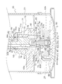
- the compressor 10 mainly includes a casing 20, a compression mechanism 30, an electric motor 50, a drive shaft 60, a lower housing 70, and an oil pump 80.
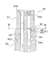
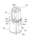
- an in-shaft oil supply path 63 and an in-shaft oil discharge path 64 for supplying oil O (refrigeration oil) to the sliding portion of the compressor 10 are formed (FIG. 1). reference).
- the in-shaft oil discharge path 64 constitutes a part of the oil discharge path 90 for discharging the oil O from a crank chamber 35 and an oil recovery space 334 described later (see FIG. 1).
- the compressor 10 has a vertically long cylindrical casing 20.
- the casing 20 includes a cylindrical member 21 that is open at the top and bottom, and an upper lid 22 a and a lower lid 22 b that are respectively provided at the upper end and the lower end of the cylindrical member 21.
- the cylindrical member 21 and the upper lid 22a and the lower lid 22b are fixed by welding so as to keep airtightness.
- the casing 20 accommodates the components of the compressor 10 including the compression mechanism 30, the electric motor 50, the drive shaft 60, the lower housing 70, and the oil pump 80.
- An oil reservoir space 25 is formed at the bottom of the casing 20 as shown in FIG. In the oil reservoir space 25, oil O for lubricating the drive shaft 60 and the sliding portion of the compression mechanism 30 is stored.
- a suction pipe 23 that sucks in a refrigerant to be compressed by the compression mechanism 30 is provided in the upper part of the casing 20 so as to penetrate the upper lid 22a.
- the lower end of the suction pipe 23 is connected to a fixed scroll 31 of the compression mechanism 30 described later.
- the suction pipe 23 communicates with a compression chamber Sc of the compression mechanism 30 described later. Low pressure refrigerant in the refrigerant circuit is supplied to the compression chamber Sc via the suction pipe 23.
- the middle part of the cylindrical member 21 of the casing 20 is provided with a discharge pipe 24 through which the refrigerant discharged outside the casing 20 passes (see FIG. 1).
- the discharge pipe 24 is disposed such that an end of the discharge pipe 24 inside the casing 20 protrudes between an upper housing 33 of the compression mechanism 30 and an electric motor 50 which will be described later. High-pressure refrigerant in the refrigerant circuit compressed by the compression mechanism 30 is discharged from the discharge pipe 24.
- the compression mechanism 30 is driven by the electric motor 50 and compresses the refrigerant.
- the compression mechanism 30 is arrange
- the compression mechanism 30 mainly includes a fixed scroll 31, a movable scroll 32, an upper housing 33, and an Oldham coupling 34.
- the fixed scroll 31 is disposed above the upper housing 33.
- the movable scroll 32 is combined with the fixed scroll 31 to form the compression chamber Sc.
- the upper housing 33 forms a crank chamber 35 in which a pin bearing portion 323 of the movable scroll 32 described later is disposed.
- the upper housing 33 has an upper bearing portion 332 that supports the drive shaft 60 below the crank chamber 35 (see FIG. 1).
- the upper housing 33 has an upper shaft seal portion 333 below the upper bearing portion 332 (see FIG. 1).
- the Oldham coupling 34 prevents the movable scroll 32 from rotating.
- the fixed scroll 31 mainly includes a fixed side end plate 311, a fixed side wrap 312, and a peripheral edge 313.
- the fixed side wrap 312 and the peripheral edge 313 protrude downward from the surface of the fixed side end plate 311 on the movable scroll 32 side, in other words, from the lower surface of the fixed side end plate 311.
- the fixed side wrap 312 is formed in a spiral shape.
- the fixed side end plate 311 is formed in a disc shape.
- the fixed side wrap 312 and the movable side wrap 322 of the movable scroll 32 to be described later are combined so that the lower surface of the fixed side end plate 311 and the upper surface of the movable side end plate 321 of the movable scroll 32 to be described later face each other.
- a compression chamber Sc in which the refrigerant is compressed is formed between 31 and the movable scroll 32 (see FIG. 1).
- the fixed side end plate 311 has a discharge port 311a and a discharge space 311b (see FIG. 1).
- the discharge port 311a is formed in the center of the fixed side end plate 311 so as to penetrate the fixed side end plate 311 in the thickness direction (see FIG. 1).
- the discharge port 311a communicates the compression chamber Sc and the discharge space 311b (see FIG. 1).
- the discharge space 311 b communicates with a space below the upper housing 33 in the casing 20 via a refrigerant passage (not shown) formed in the fixed scroll 31 and the upper housing 33.
- the refrigerant compressed in the compression chamber Sc of the compression mechanism 30 passes through a refrigerant passage (not shown) and flows into the space below the upper housing 33.
- the space below the upper housing 33 is filled with the high-pressure refrigerant compressed by the compression mechanism 30.
- the peripheral edge portion 313 is formed in a thick ring shape and is disposed so as to surround the fixed side wrap 312 (see FIG. 1).
- the upper surface of the movable side end plate 321 of the movable scroll 32 described later comes into sliding contact with the lower surface of the peripheral edge portion 313.
- the movable scroll 32 which is an example of a movable part, is connected to the drive shaft 60.
- the movable scroll 32 is driven by an electric motor 50 connected to the drive shaft 60.
- the movable scroll 32 mainly has a movable side end plate 321, a movable side wrap 322, and a pin bearing portion 323.
- the movable side end plate 321 is formed in a disc shape.
- the movable side wrap 322 protrudes upward from the surface of the movable side end plate 321 on the fixed scroll 31 side, in other words, from the upper surface of the movable side end plate 321 (see FIG. 1).
- the movable side wrap 322 is formed in a spiral shape.
- the pin bearing portion 323 protrudes downward from the surface of the movable side end plate 321 on the electric motor 50 side, in other words, from the lower surface of the movable side end plate 321 (see FIG. 1).
- the pin bearing portion 323 is formed in a cylindrical shape, and the opening at the upper end of the cylinder is closed by the movable side end plate 321.
- the pin bearing portion 323 is accommodated in a crank chamber 35, which will be described later, formed by the upper housing 33.
- the movable scroll 32 and the drive shaft 60 are connected by inserting a pin shaft portion 61 of the drive shaft 60 described later into the pin bearing portion 323.
- a bearing metal 323a is fitted into the pin bearing portion 323.
- the pin shaft portion 61 inserted into the pin bearing portion 323 is rotatably supported by the bearing metal 323a.
- An oil communication chamber 36 is provided between the upper end surface of the pin shaft portion 61 of the drive shaft 60 inserted into the pin bearing portion 323 and the lower surface of the movable side end plate 321 inside the cylindrical pin bearing portion 323. Is formed (see FIG. 1).
- the oil communication chamber 36 communicates with an in-shaft oil supply path 63 formed in a drive shaft 60 described later.
- the oil communication chamber 36 is supplied with oil O from the in-shaft oil supply path 63.
- a pin shaft channel (not shown) extending in the vertical direction is formed between the pin shaft portion 61 and the bearing metal 323a.
- the pin shaft channel has an upper end opened to the oil communication chamber 36 and a lower end opened to the crank chamber 35.
- Oil O flows from the oil communication chamber 36 into the pin shaft channel.
- the oil O that has flowed into the pin shaft channel is supplied to the sliding portion between the pin shaft portion 61 and the bearing metal 323a.
- the oil O that has been supplied to the sliding portion between the pin shaft portion 61 and the bearing metal 323 a flows into the crank chamber 35 formed by the upper housing 33.
- An oil passage 321 a is formed inside the movable side end plate 321.
- the oil passage 321a extends from the opening on the lower surface of the movable side end plate 321 communicating with the oil communication chamber 36 to the inside of the disk-shaped movable side end plate 321 outward in the radial direction, and further upwards to extend the movable side end plate 321. Open on the top surface.
- the upper housing 33 is a cylindrical member that extends vertically.
- the upper housing 33 is press-fitted into the cylindrical member 21, and the outer peripheral surface thereof is joined to the inner surface of the cylindrical member 21 over the entire circumferential direction (see FIG. 1).
- the fixed scroll 31 is fixed to the upper housing 33 with the lower surface of the peripheral edge 313 of the fixed scroll 31 and the upper end surface of the upper housing 33 facing each other (see FIG. 1).
- a drive shaft 60 is inserted into the cylindrical upper housing 33 (see FIG. 1).
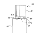
- the upper housing 33 is formed with a concave portion 331 formed so as to be recessed downward at the center of the upper surface. Further, as shown in FIG. 1, the upper housing 33 includes an upper bearing portion 332 disposed below the concave portion 331 and an upper shaft seal portion 333 disposed below the upper bearing portion 332.
- the recess 331 forms a crank chamber 35 in which the pin bearing portion 323 of the movable scroll 32 is disposed (see FIG. 1). Inside the crank chamber 35, a connecting portion between the pin shaft portion 61 of the drive shaft 60 inserted into the upper housing 33 and the movable scroll 32 is housed inside (see FIG. 1). In other words, the crank chamber 35 accommodates the pin bearing portion 323 of the movable scroll 32 into which the pin shaft portion 61 of the drive shaft 60 is inserted (see FIG. 1).
- the upper bearing portion 332 is an example of a bearing portion.
- the upper bearing portion 332 is disposed below the crank chamber 35 (see FIG. 1).
- a bearing metal 332a is provided inside the upper bearing portion 332 (see FIG. 1).
- the bearing metal 332 a rotatably supports the main shaft 62 of the drive shaft 60 inserted into the upper bearing portion 332 of the upper housing 33.
- the upper bearing portion 332 is formed with an upper bearing oil drain passage 332b extending in the vertical direction (see FIG. 1).
- the lower end of the upper bearing oil drain passage 332b communicates with an oil recovery space 334 disposed below the upper bearing portion 332 (see FIG. 1).
- the oil recovery space 334 will be described later.
- the upper end of the upper bearing oil drain passage 332 b communicates with the crank chamber 35 disposed above the upper bearing portion 332.
- the upper bearing oil drain passage 332 b is a passage that guides a part of the oil O supplied to the sliding portion between the bearing metal 332 a of the upper bearing portion 332 and the main shaft 62 of the drive shaft 60 to the crank chamber 35. .
- the oil O that has been supplied to the sliding portion between the bearing metal 332a of the upper bearing portion 332 and the main shaft 62 of the drive shaft 60 the oil O that does not flow into the crank chamber 35 enters the oil recovery space 334. Inflow.
- the upper shaft seal portion 333 is disposed below the upper bearing portion 332 (see FIG. 1).
- the upper shaft seal portion 333 is formed in a cylindrical shape.
- the inner diameter of the upper shaft seal portion 333 is substantially equal to the outer diameter of the main shaft 62 of the drive shaft 60 disposed inside the upper shaft seal portion 333.
- the inner diameter of the upper shaft seal portion 333 is slightly larger than the outer diameter of the main shaft 62 of the drive shaft 60 disposed inside the upper shaft seal portion 333.
- the upper shaft seal portion 333 prevents the oil O from leaking from the lower part of the gap between the upper housing 33 and the drive shaft 60.
- An annular space is formed between the upper bearing portion 332 and the upper shaft seal portion 333 and between the upper housing 33 and the drive shaft 60 so as to surround the drive shaft 60. Even if the annular space is formed between the main shaft 62 and the upper housing 33 by reducing the outer diameter of the main shaft 62 of the drive shaft 60, the main shaft 62 and the upper housing are increased by increasing the inner diameter of the upper housing 33. 33 may be formed.
- This space functions as an oil recovery space 334 (see FIG. 1).
- the oil recovery space 334 is formed in the lower part of the upper housing 33. Part of the oil O that has been supplied to the sliding portion between the bearing metal 332 a of the upper bearing portion 332 and the main shaft 62 of the drive shaft 60 flows into the oil recovery space 334.
- the oil recovery space 334 communicates with a second inflow path 64b (described later) of the in-shaft oil discharge path 64 formed in the drive shaft 60.
- the oil O that has flowed into the oil recovery space 334 is discharged to the oil reservoir space 25 below the casing 20 via the in-shaft oil discharge path 64.
- the discharge of the oil O from the oil recovery space 334 will be described later.
- the upper shaft seal portion 333 is provided with an upper shaft seal ring 41 (see FIG. 1).
- an upper shaft seal ring 41 is disposed between the upper shaft seal portion 333 and the drive shaft 60 below the upper shaft seal portion 333 (see FIG. 1).
- the upper shaft seal ring 41 is disposed in an annular seal ring groove 41a formed in a region of the main shaft 62 of the drive shaft 60 facing the upper shaft seal portion 333 (see FIG. 1).
- the upper shaft seal ring 41 is disposed in an annular seal ring groove formed in the upper shaft seal portion 333 instead of being disposed in the seal ring groove 41a formed in the main shaft 62 of the drive shaft 60. Also good.
- the upper shaft seal ring 41 is made of metal or resin.
- the upper shaft seal ring 41 for example, a metal material or a resin material excellent in high temperature characteristics is used.
- the upper shaft seal ring 41 is formed in an annular shape and has a joint (not shown) (not shown).
- the shape of the joint is, for example, an angle cut shape.
- the shape of the joint is not limited to this, and may be, for example, a step cut shape.
- the shape of the joint may be determined as appropriate.
- the diameter A1 of the main shaft 62 of the drive shaft 60 of the portion to which the upper shaft seal ring 41 is attached at the height h1 (see FIG. 1) in the axial direction of the upper shaft seal ring 41 (see FIG. 1, see the seal ring groove 41a).
- the value of the ratio to the diameter of the portion not formed is 0.047, but is not limited thereto.
- the value of the ratio of the height h1 in the axial direction of the upper shaft seal ring 41 to the diameter A1 of the main shaft 62 of the drive shaft 60 in the portion where the upper shaft seal ring 41 is attached is 0.04 or more and less than 0.07.
- the value of the ratio of the radial thickness w1 (see FIG. 1) of the upper shaft seal ring 41 to the diameter A1 of the main shaft 62 of the drive shaft 60 in the portion where the upper shaft seal ring 41 is attached is 0.040.
- the present invention is not limited to this.
- the value of the ratio of the radial thickness w1 of the upper shaft seal ring 41 to the diameter A1 of the main shaft 62 of the drive shaft 60 in the portion where the upper shaft seal ring 41 is attached is 0. It is preferably 0.03 or more and less than 0.06.
- the Oldham Joint 34 is provided on the upper surface of the upper housing 33 (see FIG. 1).
- the Oldham coupling 34 is slidably fitted into the movable side end plate 321 of the movable scroll 32 and the upper housing 33.
- the Oldham coupling 34 prevents the movable scroll 32 driven by the electric motor 50 from rotating. Due to the action of the Oldham coupling 34, the movable scroll 32 revolves with respect to the fixed scroll 31 without rotating.
- the electric motor 50 is disposed below the upper housing 33 of the compression mechanism 30 (see FIG. 1).
- the electric motor 50 includes a stator 51 fixed to the inner wall surface of the cylindrical member 21 and a rotor 53 that is rotatably accommodated with a slight gap (air gap) inside the stator 51 (see FIG. 1).
- the stator 51 has a cylindrical stator core 52 and windings (not shown) wound around the stator core 52.
- a core cut 52a extending in the vertical direction is formed on the outer peripheral surface of the stator core 52 (see FIG. 1). In the core cut 52 a portion, a gap is formed between the stator core 52 and the cylindrical member 21 of the casing 20.
- the compressor 10 can improve motor efficiency compared with the compressor of the type which returns the oil which accumulates in a crank chamber to an oil reservoir space through the clearance gap of a core cut part.
- the rotor 53 is formed in a cylindrical shape.
- the rotor 53 and the drive shaft 60 are connected by inserting the drive shaft 60 into the rotor 53.
- the drive shaft 60 is also connected to the movable scroll 32. That is, the rotor 53 is connected to the movable scroll 32 via the drive shaft 60.
- the electric motor 50 drives the movable scroll 32 by rotating the rotor 53.
- the drive shaft 60 extends in the vertical direction along the axis of the cylindrical member 21 of the casing 20 (see FIG. 1).
- the drive shaft 60 is connected to the rotor 53 of the electric motor 50 and transmits the driving force of the electric motor 50 to the movable scroll 32.
- the drive shaft 60 has a main shaft 62 whose central axis coincides with the central axis of the cylindrical member 21, and a pin shaft portion 61 that is eccentric with respect to the main shaft 62 (see FIG. 1).
- the pin shaft portion 61 is an example of an eccentric portion.
- the pin shaft portion 61 is formed to have a smaller diameter than the main shaft 62.
- the pin shaft portion 61 is inserted into the pin bearing portion 323 of the movable scroll 32 as described above.
- the pin shaft portion 61 is rotatably supported by a bearing metal 323a disposed inside the pin bearing portion 323.
- the main shaft 62 is rotatably supported by a bearing metal 332a of the upper bearing portion 332 of the upper housing 33 and a bearing metal 71a of a lower bearing portion 71 of the lower housing 70 described later (see FIG. 1).
- the main shaft 62 is connected to the rotor 53 of the electric motor 50 between the upper bearing portion 332 and the lower bearing portion 71 (see FIG. 1).
- the drive shaft 60 rotates around the rotation center C in plan view (see FIGS. 2 and 4).
- the rotation center C is the center position of the main shaft 62 in plan view.
- the main shaft 62 (drive shaft 60) rotates counterclockwise in plan view (see the rotation direction K in FIG. 4).
- an in-shaft oil supply path 63 for supplying oil O to the sliding portion of the compressor 10 is formed as shown in FIG. Further, as shown in FIG. 1, the drive shaft 60 communicates with the crank chamber 35 and the oil recovery space 334, and in the shaft for discharging the oil O accumulated in the crank chamber 35 and the oil recovery space 334.
- An oil drain path 64 is formed. The in-shaft oil supply path 63 and the in-shaft oil discharge path 64 will be described later.
- An oil pump shaft receiver 69 is fixed to the lower end of the main shaft 62 of the drive shaft 60 (see FIG. 1). Specifically, an oil pump shaft receiver 69 is inserted and fixed in an opening of an inflow passage 63a of an in-shaft oil supply passage 63 described later formed at the lower end of the main shaft 62.
- the oil pump shaft receiver 69 is a hollow member. As will be described later, an oil pump shaft 84 of the oil pump 80 is inserted into the hollow portion of the oil pump shaft receiver 69 from the lower end side (see FIG. 9). Inside the oil pump shaft 84, an axial relay path 84b is formed as described later (see FIG. 9). The axial relay path 84b communicates with the inflow path 63a of the in-axis oil supply path 63 into which the oil pump shaft receiver 69 is inserted (see FIG. 9).
- the lower housing 70 is disposed at the lower part in the casing 20 (see FIG. 1).
- the lower housing 70 is disposed below the electric motor 50.
- the lower housing 70 is a cylindrical member that extends vertically. A part of the outer peripheral surface of the lower housing 70 protrudes toward the cylindrical member 21 of the casing 20 (see FIG. 10), and is fixed to the cylindrical member 21.
- a drive shaft 60 is inserted into the cylindrical lower housing 70 (see FIG. 1).
- the lower housing 70 has a lower shaft seal portion 77 at the upper portion thereof (see FIG. 1). Further, the lower housing 70 has a lower bearing portion 71 below the lower shaft seal portion 77 (see FIG. 1). A recess 72 that is recessed upward is formed in the lower portion of the lower housing 70 (see FIG. 1). An oil pump 80 is fixed to the lower end surface of the lower housing 70 so as to close the opening at the bottom of the recess 72 (see FIG. 1).
- the lower bearing 71 supports the drive shaft 60.
- a bearing metal 71a is provided inside the lower bearing portion 71 (see FIG. 1).
- the bearing metal 71 a rotatably supports the main shaft 62 of the drive shaft 60 disposed in the lower bearing portion 71 of the lower housing 70.
- the lower shaft seal portion 77 is formed in a cylindrical shape.
- the inner diameter of the lower shaft seal portion 77 is substantially equal to the outer diameter of the main shaft 62 of the drive shaft 60 disposed inside the lower shaft seal portion 77.
- the inner diameter of the lower shaft seal portion 77 is slightly larger than the outer diameter of the main shaft 62 of the drive shaft 60 disposed inside the lower shaft seal portion 77.
- the lower shaft seal portion 77 prevents oil O from leaking from the upper part of the gap between the lower housing 70 and the drive shaft 60.
- annular space is formed between the lower bearing portion 71 and the lower shaft seal portion 77 and between the lower housing 70 and the drive shaft 60 so as to surround the drive shaft 60 (see FIG. 9). ). Even if the annular space is formed between the main shaft 62 and the lower housing 70 by reducing the outer diameter of a part of the main shaft 62 of the drive shaft 60, the inner diameter of a part of the lower housing 70 is reduced. And may be formed between the main shaft 62 and the lower shaft seal portion 77. This space functions as an annular space 76 (see FIG. 1). The annular space 76 is a space adjacent to the bearing metal 71a of the lower bearing portion 71 (see FIG. 9).
- the annular space 76 communicates with an oil discharge main path 64c of an in-shaft oil discharge path 64 described later and an outflow path 64d of an in-shaft oil discharge path 64 described later (see FIG. 9). Oil O that has flowed through the main oil drain path 64c and the outflow path 64d flows into the annular space 76. A part of the oil O after being supplied to the sliding portion between the bearing metal 71 a of the lower bearing portion 71 and the main shaft 62 of the drive shaft 60 flows into the annular space 76.
- the annular space 76 communicates with a lower housing oil drain path 74 formed in the lower housing 70.
- the lower housing internal oil drain path 74 is an example of an oil path.
- the lower housing internal oil drain passage 74 communicates with a lower space 78 (see FIG. 9) surrounded by the recess 72 of the lower housing 70 and the oil pump 80.
- the oil O flowing into the annular space 76 flows into the lower space 78 through the lower housing drain oil passage 74. Further, a part of the oil O after being supplied to the sliding portion between the bearing metal 71a of the lower bearing portion 71 and the main shaft 62 of the drive shaft 60 is directly (without passing through the oil draining path 74 in the lower housing). It flows into the lower space 78.
- the oil O that has flowed into the lower space 78 is guided to an oil discharge pump portion 80B of an oil pump 80, which will be described later, and flows into the oil reservoir space 25. That is, the lower housing internal oil discharge path 74 communicates the annular space 76 and the oil reservoir space 25 via the lower space 78 and the oil discharge pump portion 80B.
- a lower shaft seal ring 42 is disposed on the lower shaft seal portion 77. Since the lower shaft seal ring 42 is disposed in the lower shaft seal portion 77, the leakage of the oil O from the upper portion of the lower housing 70 can be prevented, and oil rising can be suppressed.
- a lower shaft seal ring 42 is disposed between the lower shaft seal portion 77 and the drive shaft 60 at the upper portion of the lower shaft seal portion 77 (see FIG. 9).
- the lower shaft seal ring 42 is disposed in an annular seal ring groove 42a formed in a region of the main shaft 62 of the drive shaft 60 facing the lower shaft seal portion 77 (see FIG. 9).
- the lower shaft seal ring 42 is disposed in an annular seal ring groove formed in the lower shaft seal portion 77 instead of being disposed in the seal ring groove 42a formed in the main shaft 62 of the drive shaft 60. Also good.
- the lower shaft seal ring 42 is made of metal or resin.
- the lower shaft seal ring 42 for example, a metal material or a resin material excellent in high temperature characteristics is used.
- the lower shaft seal ring 42 is formed in an annular shape, and has a joint (not shown) (not shown).
- the shape of the joint is, for example, an angle cut shape.
- the shape of the joint is not limited to this, and may be, for example, a step cut shape.
- the shape of the joint may be determined as appropriate.
- the diameter A2 of the main shaft 62 of the drive shaft 60 of the portion to which the lower shaft seal ring 42 is attached at the height h2 (see FIG. 9) in the axial direction of the lower shaft seal ring 42 (see FIG. 9, the seal ring groove 42a).
- the value of the ratio to the diameter of the non-formed portion is 0.053, but is not limited thereto.
- the value of the ratio of the axial height h2 of the lower shaft seal ring 42 to the diameter A2 of the main shaft 62 of the drive shaft 60 of the portion where the lower shaft seal ring 42 is attached is 0.04 or more and less than 0.07.
- the ratio of the radial thickness w2 (see FIG. 9) of the lower shaft seal ring 42 to the diameter A2 of the main shaft 62 of the drive shaft 60 in the portion where the lower shaft seal ring 42 is attached is 0.045.
- the present invention is not limited to this.
- the value of the ratio of the radial thickness w2 of the lower shaft seal ring 42 to the diameter A2 of the main shaft 62 of the drive shaft 60 in the portion where the lower shaft seal ring 42 is attached is 0. It is preferably 0.03 or more and less than 0.06.
- the in-shaft oil supply path 63 is an example of an oil supply path.
- the in-shaft oil supply path 63 is an oil path for supplying the oil O in the oil reservoir space 25 supplied by an oil supply pump part 80 ⁇ / b> A of the oil pump 80 described later to each sliding part of the compressor 10.
- the in-shaft oil supply path 63 is formed in the drive shaft 60 (see FIG. 1).
- the in-shaft oil supply path 63 conveys the oil O in the oil reservoir space 25 to the upper end of the pin shaft portion 61 of the drive shaft 60 disposed in the crank chamber 35. That is, the in-shaft oil supply path 63 carries the oil O in the oil reservoir space 25 to the crank chamber 35.
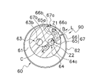
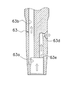
- the in-shaft oil supply path 63 mainly includes an inflow path 63a, a main oil supply path 63b, an upper outflow path 63c, and a lower outflow path 63d.
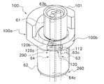
- FIG. 3 is a cross-sectional view of the upper portion of the drive shaft 60 taken along the SCS ′ cross section in FIG.
- FIG. 7 is a cross-sectional view of the lower portion of the drive shaft 60 cut along the SCT cross section in FIG. C in FIG. 2 indicates the rotation center C of the drive shaft 60.
- the inflow path 63a is a recess opening at the lower end of the drive shaft 60 (see FIG. 7).
- the inflow path 63a is formed in the central portion of the drive shaft 60 so as to be recessed upward from the lower end (see FIG. 7).
- An oil pump shaft receiver 69 is inserted into the inflow path 63a from the opening at the lower end.
- an oil pump shaft 84 of an oil pump 80 described later is inserted into the hollow oil pump shaft receiver 69.
- the inflow path 63a communicates with an axial relay path 84b formed in the oil pump shaft 84 of the oil pump 80 (see FIG. 9).
- the oil O in the oil reservoir space 25 is supplied from the inflow path 63a to the in-shaft oil supply path 63 by the oil supply pump portion 80A of the oil pump 80.
- the oil supply main path 63b extends in the drive shaft 60 in the axial direction, that is, in the vertical direction.
- the lower end of the oil supply main path 63b communicates with the inflow path 63a.
- the upper end of the oil supply main path 63 b opens at the upper end surface of the pin shaft portion 61 of the drive shaft 60.
- the oil supply main path 63 b communicates with the oil communication chamber 36.
- the upper outflow path 63c extends in the drive shaft 60 from the oil supply main path 63b in a direction crossing the axial direction.
- the upper outflow path 63c extends in the drive shaft 60 from the oil supply main path 63b in a direction orthogonal to the axial direction (see FIG. 3).
- the upper outflow path 63c extends in the drive shaft 60 in the radial direction from the oil supply main path 63b (see FIG. 2).
- the upper outflow path 63 c opens at the outer peripheral surface of the drive shaft 60 in the upper bearing portion 332 of the upper housing 33. Oil O flowing out of the opening of the outer peripheral surface of the drive shaft 60 in the upper outflow path 63 c is supplied to the sliding portion between the bearing metal 332 a of the upper bearing portion 332 and the main shaft 62 of the drive shaft 60.
- the lower outflow path 63d extends in the drive shaft 60 from the oil supply main path 63b in a direction crossing the axial direction (see FIG. 7).
- the lower outflow path 63d extends in the drive shaft 60 from the oil supply main path 63b in a direction orthogonal to the axial direction (see FIG. 7).
- the lower outflow path 63d extends in the drive shaft 60 in the radial direction from the oil supply main path 63b (see FIG. 2).
- the lower outflow path 63 d opens at the outer peripheral surface of the drive shaft 60 in the lower bearing portion 71 of the lower housing 70. Oil O flowing out of the opening of the outer peripheral surface of the drive shaft 60 in the lower outflow path 63d is supplied to the sliding portion between the bearing metal 71a of the lower bearing portion 71 and the main shaft 62 of the drive shaft 60.
- the opening on the outer peripheral surface of the drive shaft 60 in the upper outflow path 63c and the opening on the outer peripheral surface of the drive shaft 60 in the lower outflow path 63d are shifted by about 180 degrees with respect to the rotation center C of the drive shaft 60. (See FIG. 2).
- the upper outflow path 63c and the lower outflow path 63d generally extend on a straight line passing through the rotation center C of the drive shaft 60 in plan view.
- the upper outflow path 63c and the lower outflow path 63d generally extend on a straight line ST extending through the rotation center C of the drive shaft 60 in plan view.
- the opening on the outer peripheral surface of the drive shaft 60 of the upper outflow path 63c and the opening on the outer peripheral surface of the drive shaft 60 of the lower outflow path 63d are arranged symmetrically with respect to the rotation center C of the drive shaft 60.
- oil film generation at the sliding portion of the upper bearing portion 332 and the sliding portion of the lower bearing portion 71 is facilitated.
- the upper bearing portion 332 and the lower bearing portion 71 receive a load in a direction (angle) that is generally opposite to the rotation center C of the drive shaft 60 (approximately 180 degrees different).
- the form in which the upper bearing portion 332 and the lower bearing portion 71 receive the load is a so-called rotational load in which the magnitude of the load is substantially constant and the load direction varies in synchronization with the shaft rotation. Therefore, if the upper bearing portion 332 and the lower bearing portion 71 are designed to provide an opening for the outflow path on the side opposite to the direction (approximately the minimum oil film thickness position angle) for supporting the load, the upper bearing portion 332 and the lower bearing portion will be described.
- the flow rate of the oil O supplied to the part 71 can be increased most.
- an oil supply main path 63 b that extends in the axial direction from the inflow path 63 a at a position symmetrical to the oil supply main path 63 b with respect to the rotation center C of the drive shaft 60.
- the lower outflow path 63d may be connected to the lower bearing dedicated path 63e instead of the oil supply main path 63b, and the oil O may be supplied to the lower outflow path 63d via the lower bearing dedicated path 63e.
- the flow of the oil O flowing through the lower outflow path 63 d also becomes a flow along the centrifugal force, and the oil O is easily supplied to the lower bearing portion 71.
- the oil discharge route 90 is used to remove the oil O in the crank chamber 35 and the oil recovery space 334 and the oil O supplied to the lower bearing portion 71 from the oil pump 80. This is an oil path leading to the pump unit 80B.
- the oil drainage path 90 mainly includes an in-shaft oil drainage path 64, an annular space 76, a lower housing drainage oil path 74, and a lower space 78 surrounded by the recess 72 of the lower housing 70 and the oil pump 80. Included (see FIG. 1).
- the in-shaft oil discharge path 64 guides the oil O in the crank chamber 35 and the oil recovery space 334 to the annular space 76 formed around the main shaft 62 of the drive shaft 60.
- the oil O in the annular space 76 is conveyed to the lower space 78 through the lower housing drain oil passage 74.
- the oil O collected in the crank chamber 35 includes the oil O after being supplied to the sliding portion between the pin shaft portion 61 of the drive shaft 60 and the bearing metal 323a of the pin bearing portion 323.
- the oil O accumulated in the crank chamber 35 is supplied to the sliding portion between the main shaft 62 of the drive shaft 60 and the bearing metal 332a of the upper bearing portion 332, and then passes through the upper bearing oil drain passage 332b.
- Oil O flowing into the The oil O flowing into the oil recovery space 334 includes the oil O after being supplied to the sliding portion between the main shaft 62 of the drive shaft 60 and the bearing metal 332a of the upper bearing portion 332.
- the oil O flowing into the annular space 76 is supplied to the sliding portion between the oil O flowing through the in-shaft oil discharge path 64 and the main shaft 62 of the drive shaft 60 and the bearing metal 71a of the lower bearing portion 71. Part of oil O.
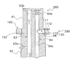
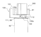
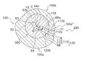
- the in-shaft oil discharge path 64 mainly has a first inflow path 67, a second inflow path 64b, a main oil discharge path 64c, and an outflow path 64d (see FIG. 1).
- the first inflow path 67 communicates the oil drain main path 64c and the crank chamber 35 (see FIG. 1).
- the first inflow path 67 is formed at the base of the pin shaft portion 61 (see FIGS. 3, 5 and 6).
- the pin shaft portion 61 of the drive shaft 60 is disposed in the crank chamber 35 formed by the upper housing 33.
- the space in the in-shaft oil discharge path 64 (the space in the pin shaft portion 61), A space different from the crank chamber 35 is defined. That is, in the cross-sectional view of FIG. 4, the space inside the first inflow path 67 and the oil drain main path 64 c formed inside the outer peripheral edge of the pin shaft portion 61 is defined as a space different from the crank chamber 35. .
- the oil drain main path 64c is a hole extending in the axial direction, that is, in the vertical direction, inside the drive shaft 60.
- the oil drain main path 64c is formed in a circular shape in plan view.
- the oil drain main path 64 c extends from the upper end surface of the pin shaft portion 61 of the drive shaft 60 to the lower portion of the drive shaft 60.
- the opening at the upper end of the oil drain main path 64c is closed by a plug 64e (see FIG. 1). For this reason, the oil drain main path 64 c does not communicate with the oil communication chamber 36 formed above the pin shaft portion 61.
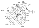
- the first inflow path 67 mainly has a suction hole 65 and an introduction portion 66 (see FIGS. 3 and 4).
- the suction hole 65 is an example of the vicinity of the outlet.
- the suction hole 65 is a hole that opens to the oil drain main path 64c.
- the opening of the suction hole 65 to the oil drain main path 64c is referred to as an inflow path outlet 67b (see FIGS. 4 to 6). That is, the suction hole 65 is provided in the vicinity of the inflow path outlet 67b, more specifically, adjacent to the inflow path outlet 67b.
- the inflow path outlet 67b is an opening formed at the outer peripheral edge of the oil drain main path 64c.
- the inflow path outlet 67b is an opening formed on the outer peripheral surface of the cylindrical member by opening the suction hole 65 when the oil drain main path 64c is assumed to be a substantial cylindrical member. is there.
- the inflow route outlet 67b is arranged in a section indicated by a double-headed arrow in FIG. 4 on the outer peripheral edge of the oil drainage main route 64c in plan view.
- the suction hole 65 extends linearly from the oil drain main path 64c, in other words, from the inflow path outlet 67b.
- the suction hole 65 is a hole formed in a circular shape when viewed from the side (when viewed from a direction orthogonal to the axial direction of the drive shaft 60) (see FIG. 6). Therefore, the inflow path outlet 67b is also formed in a circular shape in a side view (see FIG. 6).
- the suction hole 65 extends along a straight line that intersects the axial direction of the drive shaft 60.
- the suction hole 65 extends along a straight line orthogonal to the axial direction of the drive shaft 60.
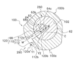
- the suction hole 65 is along a straight line L passing through the rotation center C of the drive shaft 60 (center of the main shaft 62) and the centroid Z2 of the inflow path outlet 67b in a plan view and orthogonal to the axial direction of the drive shaft 60. (See FIG. 3).
- centroid Z2 of the inflow path outlet 67b in plan view is a section where the inflow path outlet 67b on the outer peripheral edge of the oil drain main path 64c is disposed (on the outer peripheral edge of the oil main path 64c in FIG. 4).
- the suction hole 65 has a pair of straight portions 65a extending linearly from the inflow path outlet 67b in plan view (see FIG. 4). Both straight portions 65a extend from the inflow path outlet 67b in parallel to the straight line L toward the outside of the pin shaft portion 61 (see the direction of the arrow in the direction B in FIG. 4).
- the introduction portion 66 is formed at the base portion of the pin shaft portion 61 so as to wind the inside of the pin shaft portion 61 from the outer peripheral surface of the pin shaft portion 61 (see FIG. 5).
- the introduction portion 66 is disposed on one of the outer peripheral edge of the pin shaft portion 61 (a section indicated by a double arrow in FIG. 4 where an inflow path inlet 67a described later is formed) and the straight portion 65a of the suction hole 65.
- This is a space surrounded by a first surface 66 a that extends continuously, a second surface 66 b that extends in a direction orthogonal to the straight line L, and the suction hole 65.
- the introduction portion 66 is formed to extend in a direction orthogonal to the straight line L (a direction in which the second surface 66b extends) longer than a direction of the straight line L (a direction in which the first surface 66a extends) in plan view.
- the introduction part 66 is a space communicating with the suction hole 65 (see FIGS. 3 and 4).
- the introduction portion 66 is a space communicating with the crank chamber 35 (see FIGS. 3 and 4). In other words, the introduction part 66 opens into the crank chamber 35.
- the opening of the introduction portion 66 into the crank chamber 35 is called an inflow path inlet 67a (see FIGS. 4 to 6).
- the inflow path inlet 67a is an opening formed on the outer peripheral edge of the pin shaft portion 61 (see FIG. 5).
- the inflow path inlet 67a is disposed in a section indicated by a double-headed arrow in FIG. 4 on the outer peripheral edge of the pin shaft portion 61 in plan view.
- the inflow path inlet 67a is formed in a rectangular shape that extends long in the horizontal direction in a side view from the direction facing the second surface 66b of the introduction portion 66 (see FIG. 6).
- the oil O in the crank chamber 35 flows into the introduction portion 66 through the inflow path inlet 67a.
- An inflow path inlet 67a (inflow path inlet 67a that opens to the crank chamber 35) that is an inlet of oil O from the crank chamber 35 to the first inflow path 67, and an oil O from the first inflow path 67 to the exhaust oil main path 64c.
- the inflow path outlet 67b (the inflow path outlet 67b opened to the oil drain main path 64c), which is the outlet of
- the area of the inflow path inlet 67a formed on the outer peripheral surface of the pin shaft portion 61 is larger than the area of the inflow path outlet 67b formed on the outer peripheral edge of the oil drain main path 64c (see FIGS. 5 and 6).
- the inflow path inlet 67a is biased forward in the rotational direction K of the drive shaft 60 from the inflow path outlet 67b.
- the centroid Z1 of the inflow path inlet 67a is located on the front side in the rotational direction K of the drive shaft 60 with respect to the straight line L extending in the direction B through the centroid Z2 of the inflow path outlet 67b. (See FIG. 4).
- the centroid Z1 of the inflow path inlet 67a in a plan view is a section where the inflow path inlet 67a on the outer peripheral edge of the pin shaft portion 61 is arranged (a double arrow on the outer peripheral edge of the pin shaft portion 61 in FIG. 4).
- centroid of the virtual figure when a figure with a very small width extending along the outer peripheral edge of the pin shaft portion 61 is assumed in the section shown).
- centroid Z1 of the inflow path inlet 67a rotates with respect to the straight line L extending from the rotation center C of the drive shaft 60 through the centroid Z2 of the inflow path outlet 67b. It is located on the front side in the direction K (see FIG. 4).
- the area of the inflow path inlet 67a is configured to be larger than the area of the inflow path outlet 67b, so that the area of the inflow path inlet 67a is not larger than the area of the inflow path outlet 67b.
- the oil O in the chamber 35 is easily guided to the oil exhaust main path 64 c by the first inflow path 67.
- the inflow path inlet 67a is biased forward in the rotational direction K of the drive shaft 60 relative to the inflow path outlet 67b, so that when the drive shaft 60 rotates, the inflow direction K
- the oil O is easily guided to the introduction portion 66 from the inflow path inlet 67a disposed on the front side of the inflow path outlet 67b, and the oil O is easily guided to the oil drain main path 64c.
- the introduction portion 66 has a first surface 66a that extends in a direction intersecting the rotation direction K.
- the first surface 66a is an example of a guide surface.
- the first surface 66a is linear with the straight portion 65a of the suction hole 65 on the rear side in the rotation direction K of the drive shaft 60 (the straight portion 65a of the suction hole 65 on the rear side in the rotation direction K with respect to the straight line L) in plan view. (See FIG. 4). That is, the introduction portion 66 has a first surface 66a extending in parallel with the straight line L in plan view (see FIG. 4).
- the suction hole 65 is formed by a drill, and then the introduction portion 66 is formed by an end mill.
- transducing part 66 is an illustration, and is not limited to this.
- Various processing methods can be applied to the method of forming the suction hole 65 and the introduction portion 66.
- the second inflow path 64b communicates the main oil drain path 64c and the oil recovery space 334.
- the second inflow path 64b extends in the drive shaft 60 from the oil drain main path 64c in a direction crossing the axial direction.
- the second inflow path 64b extends in the drive shaft 60 in a direction orthogonal to the axial direction.
- the second inflow path 64b extends in the radial direction in the drive shaft 60 from the oil drain main path 64c.
- the second inflow path 64 b is formed at a height position of the oil recovery space 334 of the upper housing 33.
- the second inflow path 64 b opens on the outer peripheral surface of the drive shaft 60 in the oil recovery space 334 formed above the upper shaft seal portion 333.
- the second inflow path 64b has one end communicating with the oil recovery space 334 and the other end communicating with the oil drain main path 64c.
- the oil O in the oil recovery space 334 flows into the in-shaft oil discharge path 64 from the opening of the second inflow path 64b.
- the oil O after being supplied to the sliding portion between the bearing metal 332 a of the upper bearing portion 332 and the main shaft 62 of the drive shaft 60. Are all introduced into the crank chamber 35, and are introduced from the first inflow path 64a into the oil drain main path 64c.
- the oil O after being supplied to the sliding portion between the bearing metal 332a of the upper bearing portion 332 and the main shaft 62 of the drive shaft 60 is second.
- the inflow path 64b can also flow into the oil drain main path 64c. Therefore, the oil O can be prevented from being excessively accumulated in the crank chamber 35.
- the outflow path 64d extends in the drive shaft 60 from the lower end of the oil drain main path 64c in a direction crossing the axial direction. Particularly, here, the outflow path 64d extends in the drive shaft 60 from the lower end of the oil drain main path 64c in a direction orthogonal to the axial direction. The outflow path 64d extends in the drive shaft 60 in the radial direction from the lower end of the oil drain main path 64c.
- the outflow path 64 d is open to the outer peripheral surface of the main shaft 62 of the drive shaft 60 in an annular space 76 formed between the lower housing 70 and the main shaft 62 of the drive shaft 60. That is, the outflow path 64 d communicates with the annular space 76.
- the oil O that has flowed into the annular space 76 is discharged to a lower space 78 surrounded by the recess 72 of the lower housing 70 and the oil pump 80 via a lower housing drain oil passage 74 formed in the lower housing 70.
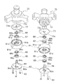
- Oil Pump 80 is a so-called double trochoidal positive displacement pump.
- the oil pump 80 is fixed to the lower end surface of the lower housing 70 with bolts 83 as shown in FIG.
- the oil pump 80 mainly includes a thrust plate 73, a pump body 81, a pump cover 82, an oil pump shaft 84, a lower outer rotor 85, a lower inner rotor 86, an upper outer rotor 87, and an upper inner rotor 88.
- the oil pump 80 includes an oil supply pump portion 80A that supplies the oil O in the oil reservoir space 25 to the in-shaft oil supply path 63, and a drain that discharges the oil O in the crank chamber 35 to the oil reservoir space 25 through the oil discharge path 90.
- Oil pump unit 80B (see FIG. 9).
- Oil supply pump unit 80A is an example of an oil supply pump.
- the oil discharge pump unit 80B is an example of an oil discharge pump.
- the oil supply pump portion 80A includes a lower outer rotor 85 and a lower inner rotor 86 (see FIG. 9).
- the oil discharge pump unit 80B includes an upper outer rotor 87 and an upper inner rotor 88 (see FIG. 9).
- a driving force is transmitted by the oil pump shaft 84 to the lower inner rotor 86 of the oil supply pump portion 80A and the upper inner rotor 88 of the oil discharge pump portion 80B.
- the oil pump shaft 84 is connected to the lower part of the drive shaft 60, and when the drive shaft 60 rotates, the oil pump shaft 84 also rotates.
- the oil supply pump portion 80A is a positive displacement oil pump
- the oil discharge pump portion 80B is a positive displacement oil pump. Function.
- the thrust plate 73 is formed in a disc shape (see FIG. 10).
- the thrust plate 73 is attached to the lower housing 70 so as to close the recess 72 formed in the lower housing 70 (see FIGS. 9 and 10).
- the lower end surface of the oil pump shaft receiver 69 attached to the lower end of the drive shaft 60 is in sliding contact with the thrust plate 73 (see FIG. 9).
- the thrust plate 73 receives the thrust force of the drive shaft 60.
- An insertion hole 73b for inserting the lower part of the oil pump shaft 84 is formed in the central portion in the radial direction of the thrust plate 73 (see FIGS. 9 and 10). Further, a discharge port 73a for guiding the oil O in the lower space 78 above the thrust plate 73 to the oil discharge pump portion 80B is formed in the outer peripheral portion of the thrust plate 73 (see FIGS. 9 and 10). .
- the upper end of the discharge port 73a communicates with the lower space 78, and the lower end communicates with an in-body upper flow path 81b of the pump body 81 described later.
- the pump body 81 is a substantially cylindrical member extending in the vertical direction.
- An oil pump shaft 84, a lower outer rotor 85, a lower inner rotor 86, an upper outer rotor 87, and an upper inner rotor 88 are accommodated inside the pump body 81 (see FIG. 9).
- An outer peripheral edge 81a protruding upward is formed on the periphery of the upper portion of the pump body 81 (see FIG. 10).
- the pump body 81 is fixed to the lower housing 70 with the thrust plate 73 fitted inside the outer peripheral edge 81a (see FIG. 9).
- an in-body upper channel 81b that is recessed downward is formed (see FIGS. 9 and 10).
- an in-body lower channel 81c that is recessed upward is formed (see FIGS. 9 and 10).
- the in-body lower flow path 81c is formed in a circular shape in plan view.
- an inner peripheral hole 81d into which the oil pump shaft 84 is inserted is formed at the center of the pump body 81 (see FIGS. 9 and 10).
- the pump body 81 is formed with a discharge passage 81e extending in the horizontal direction and penetrating the inside and outside (see FIGS. 9 and 10).
- a discharge passage 81e As for the discharge flow path 81e, one end (end part on the inner side) opens to the upper flow path 81b in the body, and the other end (end part on the outer side) opens to the outer peripheral surface of the pump body 81 (see FIG. 9). ).
- a pump outlet pipe 89 is attached to the discharge flow path 81e (see FIG. 9).
- the pump outlet pipe 89 is formed in an L shape.
- the pump outlet pipe 89 extends in the horizontal direction along the discharge flow path 81e, and then changes the direction by 90 degrees and extends downward.
- the lower end of the pump outlet pipe 89 is disposed below the lower end of the oil pump 80. Further, the lower end of the pump outlet pipe 89 is disposed in the lower part of the oil reservoir space 25.
- the pump outlet pipe 89 guides the oil O that has flowed from the oil discharge pump unit 80B through the discharge flow path 81e to the lower part of the oil reservoir space 25.
- the oil O is not discharged in the horizontal direction from the discharge flow path 81e, but is discharged to the lower part of the oil reservoir space 25 by the pump outlet pipe 89, so that the mist of the oil O is carried together with the refrigerant. It can prevent discharging from the discharge pipe 24 to a refrigerant circuit. Further, since the discharge flow path 81e opens near the liquid level of the oil reservoir space 25, when there is no pump outlet pipe 89, the oil O discharged from the discharge flow path 81e disturbs the liquid level, There is a possibility that scattering of oil O mist may be promoted. In contrast, here, since the oil O is discharged to the lower portion of the oil reservoir space 25 by the pump outlet pipe 89, the liquid level of the oil reservoir space 25 is not disturbed.
- the pump cover 82 is formed in a substantially disc shape (see FIG. 10).
- the pump cover 82 is fixed to the lower surface of the pump body 81 (see FIGS. 9 and 10).
- the oil pump shaft 84 is rotatably supported at the center of the pump cover 82 (see FIGS. 9 and 10). Further, the pump cover 82 is formed with an arcuate suction port 82a on the outer peripheral side of the oil pump shaft 84 supported by the pump cover 82 in plan view (see FIGS. 9 and 10).
- the suction port 82a is formed so as to penetrate the pump cover 82 in the vertical direction.
- the lower end of the suction port 82 a is open to the oil reservoir space 25.
- the upper end of the suction port 82 a opens into a lower body flow path 81 c formed in the pump body 81.
- the oil pump shaft 84 is formed in a cylindrical shape and extends in the vertical direction (see FIG. 9). The lower part of the oil pump shaft 84 is rotatably supported by the pump cover 82 (see FIGS. 9 and 10). The oil pump shaft 84 is inserted into an inner peripheral hole 81d formed in the pump body 81, and is rotatably supported by the pump body 81 (see FIGS. 9 and 10). The oil pump shaft 84 is inserted into the insertion hole 73b of the thrust plate 73 disposed on the upper portion of the pump body 81 (see FIGS. 9 and 10).
- the oil pump shaft 84 is inserted from below into an oil pump shaft receiver 69 attached to an inflow path 63 a formed at the lower end of the main shaft 62 of the drive shaft 60, and is fitted to the oil pump shaft receiver 69. (See FIGS. 9 and 10). Specifically, the upper end portion of the oil pump shaft 84 formed in a hexagonal shape is inserted into a hexagonal hole provided in the inner diameter portion of the oil pump shaft receiver 69. That is, the oil pump shaft 84 is connected to the lower part of the drive shaft 60 via the oil pump shaft receiver 69. By connecting the oil pump shaft 84 and the drive shaft 60, the oil pump shaft 84 rotates integrally with the drive shaft 60.
- a radial relay path 84a and an axial relay path 84b are formed (see FIGS. 9 and 10).
- the radial relay path 84a penetrates the oil pump shaft 84 in the radial direction (see FIG. 9).
- the radial relay path 84 a opens to the body lower flow path 81 c of the pump body 81.
- the axial relay path 84b extends in the axial direction (vertical direction) through the oil pump shaft 84.
- the axial relay path 84b opens at the upper end surface of the oil pump shaft 84 and communicates with an inflow path 63a of an in-shaft oil supply path 63 formed inside the drive shaft 60 (see FIG. 9).
- the lower end of the axial relay path 84b communicates with the radial relay path 84a (see FIG. 9).
- the oil pump shaft 84 rotates, the oil O in the lower flow path 81c in the body passes through the radial relay path 84a and the axial relay path 84b and is supplied to the in-shaft oil supply path 63 (see FIG. 9). ).
- the lower outer rotor 85 is fitted in the lower flow path 81c in the body.
- the lower outer rotor 85 is formed in an annular shape, and a plurality of arcuate (more strictly, trochoidal curve) outer teeth 85a are formed on the inner peripheral surface thereof (see FIG. 10).
- the plurality of outer teeth 85a are arranged at equal intervals in the circumferential direction and bulge toward the lower inner rotor 86 disposed inside the lower outer rotor 85.
- the lower inner rotor 86 is formed in an annular shape (see FIG. 10).
- the lower inner rotor 86 is disposed inside the lower outer rotor 85 (see FIG. 9).
- the lower inner rotor 86 is fitted to the outside of the oil pump shaft 84.
- a D-shaped holding hole 86a is formed inside the lower inner rotor 86 (see FIG. 10).
- a plurality of inner teeth 86b are formed on the outer peripheral surface of the lower inner rotor 86 so as to correspond to the outer teeth 85a of the lower outer rotor 85 (see FIG. 10).
- the lower inner rotor 86 is disposed inside the lower outer rotor 85 so that the inner tooth portion 86b and the outer tooth portion 85a mesh with each other, so that the inner tooth portion 86b and the outer tooth portion 85a are interposed between each other.
- a volume chamber V1 for conveying the oil O is formed (see FIG. 9).
- the lower part of the oil pump 80 including the lower inner rotor 86 and the lower outer rotor 85 constitutes an oil supply pump portion 80A.
- the oil O in the oil reservoir space 25 flows from the suction port 82a of the pump cover 82, and between the lower inner rotor 86 and the lower outer rotor 85 in the lower flow path 81c in the body.
- the upper outer rotor 87 is fitted in the body upper flow path 81b.
- the upper outer rotor 87 is formed in an annular shape, and a plurality of outer teeth 87a having an arc shape (more precisely, a trochoid curve shape) are formed on the inner peripheral surface thereof (see FIG. 10).
- the plurality of outer teeth 87a are arranged at equal intervals in the circumferential direction and bulge toward the upper inner rotor 88 disposed inside the upper outer rotor 87.
- the upper inner rotor 88 is formed in an annular shape (see FIG. 10).
- the upper inner rotor 88 is disposed inside the upper outer rotor 87 (see FIG. 9).
- the upper inner rotor 88 is fitted to the outside of the oil pump shaft 84.
- a D-shaped holding hole 88a is formed inside the upper inner rotor 88 (see FIG. 10).
- a plurality of inner teeth 88b are formed on the outer peripheral surface of the upper inner rotor 88 so as to correspond to the outer teeth 87a of the upper outer rotor 87 (see FIG. 10).
- the upper inner rotor 88 is disposed inside the upper outer rotor 87 so that the inner tooth portion 88b and the outer tooth portion 87a mesh with each other, so that oil is provided between the inner tooth portion 88b and the outer tooth portion 87a.
- a volume chamber V2 for conveying O is formed (see FIG. 9).
- the volume chamber V ⁇ b> 2 between the upper inner rotor 88 and the upper outer rotor 87 is larger than the volume chamber V ⁇ b> 1 between the lower inner rotor 86 and the lower outer rotor 85.
- the upper part of the oil pump 80 including the upper inner rotor 88 and the upper outer rotor 87 constitutes an oil discharge pump portion 80B.
- the oil O flows from the lower space 78 constituting a part of the oil discharge path 90 through the discharge port 73a of the thrust plate 73 into the body upper flow path 81b, and the body upper flow path
- the oil reservoir space at the bottom of the casing 20 passes through the discharge passage 81 e formed on the side surface of the pump body 81.
- the volume chamber V2 between the upper inner rotor 88 and the upper outer rotor 87 is larger than the volume chamber V1 between the lower inner rotor 86 and the lower outer rotor 85.
- the discharge amount of the pump unit 80B is larger than the discharge amount of the oil supply pump unit 80A.
- the discharge amount here means the theoretical discharge amount of the oil supply pump unit 80A and the oil discharge pump unit 80B.
- the actual discharge amount of the oil discharge pump unit 80B may be smaller than the actual discharge amount of the oil supply pump unit 80A.
- the electric motor 50 is operated and the rotor 53 rotates.
- the drive shaft 60 connected to the rotor 53 also rotates.
- the pin shaft portion 61 rotates eccentrically.
- the movable scroll 32 in which the pin shaft portion 61 is inserted into the pin bearing portion 323 turns.
- the movable scroll 32 revolves with respect to the fixed scroll 31 without rotating due to the action of the Oldham coupling 34.
- the low-pressure refrigerant in the refrigerant circuit is sucked into the casing 20 through the suction pipe 23.
- the low-pressure refrigerant in the refrigerant circuit passes through the suction pipe 23 and is sucked from the peripheral side of the fixed side wrap 312 to the compression chamber Sc.
- the suction pipe 23 and the compression chamber Sc no longer communicate with each other.
- compression chamber Sc approaches the center part from the peripheral side, reducing the volume. Thereby, the pressure of the refrigerant in the compression chamber Sc increases.
- the high-pressure refrigerant compressed by the compression mechanism 30 is discharged into the discharge space 311b through the discharge port 311a formed near the center of the fixed side end plate 311.
- the high-pressure refrigerant in the refrigerant circuit discharged into the discharge space 311 b passes through a refrigerant passage (not shown) formed in the fixed scroll 31 and the upper housing 33 and flows into a space below the upper housing 33.
- the high-pressure refrigerant flowing into the space below the upper housing 33 is discharged from the discharge pipe 24 and sent to the refrigerant circuit.
- the oil supply pump unit 80A of the oil pump 80 is driven. Specifically, when the oil pump shaft 84 connected to the drive shaft 60 rotates, the lower inner rotor 86 rotates inside the lower outer rotor 85. As a result, the volume of the volume chamber V ⁇ b> 1 expands and contracts, and the oil O in the oil reservoir space 25 is sucked into the oil supply pump portion 80 ⁇ / b> A of the oil pump 80.
- the oil O in the oil reservoir space 25 is sucked into the volume chamber V1 in the lower flow path 81c in the body through the suction port 82a of the pump cover 82.
- the oil O discharged from the volume chamber V ⁇ b> 1 flows through the radial relay path 84 a and the axial relay path 84 b and flows into the inflow path 63 a of the in-shaft oil supply path 63.
- the oil O that has flowed into the inflow path 63a of the in-shaft oil supply path 63 ascends the oil supply main path 63b. Further, when the lower bearing dedicated path 63e is provided as in the embodiment of FIG. 8, the oil O that has flowed into the inflow path 63a rises in the oil supply main path 63b and the lower bearing dedicated path 63e.
- the oil O flows out into the annular space 76 formed below the lower shaft seal portion 77 of the lower housing 70 or the lower space 78 surrounded by the recess 72 of the lower housing 70.
- the oil O that has flowed into the annular space 76 flows out to the lower space 78 via the lower housing drain oil passage 74.
- a part of the oil O that rises in the oil supply main path 63b is supplied to the upper bearing portion 332 through the upper outflow path 63c.
- the oil O supplied to the upper bearing portion 332 lubricates the sliding portion between the bearing metal 332a and the main shaft 62 of the drive shaft 60.
- part of the oil O passes through the upper bearing oil drain passage 332 b and flows into the crank chamber 35 formed by the upper housing 33.
- the remaining oil O flows into an oil recovery space 334 formed above the upper shaft seal portion 333 below the upper housing 33.
- the oil O that has flowed into the oil passage 321a is supplied to the thrust surface between the fixed scroll 31 and the movable scroll 32, the gap between the fixed side wrap 312 and the movable side wrap 322, and the like.
- the oil O flowing into the pin shaft channel is supplied to the sliding portion between the bearing metal 323a in the pin bearing portion 323 and the pin shaft portion 61 of the drive shaft 60, and lubricates the sliding portion. Thereafter, the oil O flows out into the crank chamber 35 formed by the upper housing 33.
- the oil discharge pump unit 80B of the oil pump 80 is also driven. Specifically, when the oil pump shaft 84 connected to the drive shaft 60 rotates, the upper inner rotor 88 rotates inside the upper outer rotor 87. As a result, the volume of the volume chamber V2 of the oil discharge pump portion 80B is expanded and contracted, and the oil O of the crank chamber 35 flows into the introduction portion 66 from the inflow path inlet 67a. The oil O that has flowed into the introduction portion 66 is guided by the first surface 66a, flows into the suction hole 65, passes through the suction hole 65, and flows into the oil drain main path 64c.
- the oil O in the oil recovery space 334 flows into the oil exhaust main path 64c through the second inflow path 64b.
- the oil O that has flowed into the drained oil main path 64c from the first inflow path 67 and the second inflow path 64b moves downward in the drained oil main path 64c, passes through the outflow path 64d, and flows out into the annular space 76.
- the oil O that has flowed into the annular space 76 passes through the lower housing drain oil passage 74 and flows into the lower space 78 surrounded by the recess 72 of the lower housing 70.
- the oil O in the lower space 78 flows through the discharge port 73 a formed in the thrust plate 73 and flows into the oil discharge pump portion 80 ⁇ / b> B of the oil pump 80.
- the oil O that has passed through the discharge port 73a flows into the in-body upper flow path 81b and is sucked into the volume chamber V2 in the in-body upper flow path 81b.
- the oil O discharged from the volume chamber V ⁇ b> 2 passes through a discharge passage 81 e formed inside the pump body 81, and is discharged to the oil reservoir space 25 at the bottom of the casing 20 through the pump outlet pipe 89.
- the compressor 10 of the present embodiment includes a casing 20, an electric motor 50, a drive shaft 60, a compression mechanism 30, an in-shaft oil supply path 63 as an example of an oil supply path, an oil discharge path 90, and an example of an oil supply pump.
- a fuel oil pump unit 80A, and a fuel oil pump unit 80B as an example of a fuel oil pump.
- the casing 20 has an oil reservoir space 25 formed at the bottom.
- the electric motor 50 is accommodated in the casing 20.
- the drive shaft 60 extends in the vertical direction and is connected to the electric motor 50.
- the compression mechanism 30 includes a movable scroll 32 as an example of a movable part, and an upper housing 33.
- the movable scroll 32 is connected to the drive shaft 60 and is driven by the electric motor 50.
- the upper housing 33 forms a crank chamber 35 in which a connecting portion between the pin shaft portion 61 of the drive shaft 60 and the movable scroll 32 (pin bearing portion 323 of the movable scroll 32) is accommodated.
- the pin shaft portion 61 is an example of an eccentric portion of the drive shaft 60.
- the compression mechanism 30 is accommodated in the casing 20.
- the upper housing 33 has an upper bearing portion 332 that supports the drive shaft 60 below the crank chamber 35.
- the in-shaft oil supply path 63 carries the oil O in the oil reservoir space 25 to the crank chamber 35.
- the in-shaft oil supply path 63 is formed inside the drive shaft 60.
- the oil discharge path 90 includes a main oil discharge path 64 c and a first inflow path 67.
- the oil drain main path 64c extends in the axial direction inside the drive shaft 60.
- the first inflow path 67 communicates the oil drain main path 64 c and the crank chamber 35.
- the oil supply pump unit 80 ⁇ / b> A supplies the oil O in the oil reservoir space 25 to the in-shaft oil supply path 63.
- the oil discharge pump unit 80 ⁇ / b> B discharges the oil O in the crank chamber 35 to the oil reservoir space 25 through the oil discharge path 90.
- An oil recovery space 334 is formed below the crank chamber 35 and below the upper housing 33.
- the in-shaft oil discharge path 64 further includes a second inflow path 64b that allows the oil discharge main path 64c and the oil recovery space 334 to communicate with each other.
- the oil drain path 90 is communicated with an oil recovery space 334 formed below the crank chamber 35 and below the upper housing 33. 2 inflow path 64b. Therefore, it is possible to increase the amount of oil O flowing into the oil drain main path 64c, and it is possible to prevent the oil O from being accumulated in the crank chamber 35 and the pressure from rising excessively.
- the oil recovery space 334 is formed below the upper bearing portion 332.
- the oil O that may leak from the lower portion of the upper housing 33 reaching below the upper bearing portion 332 can be guided to the oil reservoir space 25 via the in-shaft oil discharge path 64, and the upper housing It is possible to prevent oil from rising due to the oil O leaking from the lower portion of 33.
- the upper housing 33 has an upper shaft seal portion 333 disposed below the oil recovery space 334.
- the compressor 10 includes an upper shaft seal ring 41 disposed on the upper shaft seal portion 333.
- the upper shaft seal ring 41 is disposed in the upper shaft seal portion 333 below the oil recovery space 334, even when the pressure in the crank chamber 35 rises, the oil O flows from the lower portion of the upper housing 33. Leakage can be prevented and oil rise can be suppressed.
- the upper shaft seal ring 41 may not be provided, it is preferable to provide the upper shaft seal ring 41 in order to easily prevent the oil O from leaking from the lower portion of the upper housing 33.
- the compressor 10 of this embodiment includes a lower housing 70 and a lower shaft seal ring 42.
- the lower housing 70 has a lower bearing portion 71 and a lower shaft seal portion 77.
- the lower bearing portion 71 supports the drive shaft 60.
- the lower shaft seal portion 77 is disposed above the lower bearing portion 71.
- the lower shaft seal ring 42 is disposed on the lower shaft seal portion 77.
- the lower shaft seal ring 42 is disposed in the lower shaft seal portion 77 of the lower housing 70, leakage of the oil O from the upper portion of the lower housing 70 can be prevented, and oil rising can be further suppressed.
- the lower shaft seal ring 42 may not be provided, it is preferable to provide the lower shaft seal ring 42 in order to easily prevent the oil O from leaking from the upper portion of the lower housing 70.
- the annular space 76 is disposed below the lower shaft seal portion 77.
- the annular space 76 is formed so as to surround the drive shaft 60.
- the annular space 76 communicates with the oil drain main path 64c.
- the lower housing 70 is formed with a lower housing drain oil passage 74 that allows the annular space 76 and the oil reservoir space 25 to communicate with each other.
- the lower housing internal oil drain path 74 is an example of an oil path.
- the drive shaft 60 is formed with a seal ring groove 42a in which the lower shaft seal ring 42 is disposed.
- the seal ring groove 42 a for disposing the lower shaft seal ring 42 is provided on the drive shaft 60 side, it is easy to assemble the compressor 10 in which the lower shaft seal ring 42 is disposed in the lower shaft seal portion 77. is there.
- the drive shaft 60 is formed with a seal ring groove 41a in which the upper shaft seal ring 41 is disposed.
- the seal ring groove 41a in which the upper shaft seal ring 41 is disposed is provided on the drive shaft 60 side, it is easy to assemble the compressor 10 in which the upper shaft seal ring 41 is disposed in the upper shaft seal portion 333. is there.
- the discharge amount of the oil discharge pump unit 80B is larger than the discharge amount of the oil supply pump unit 80A.
- the discharge amount here means the theoretical discharge amount of the oil supply pump unit 80A and the oil discharge pump unit 80B.
- the discharge amount of the oil discharge pump unit 80B that discharges the oil O from the crank chamber 35 is larger than the discharge amount of the oil supply pump unit 80A that carries the oil O to the crank chamber 35, the oil O in the crank chamber 35 is discharged. It is easy to be discharged through the route 90. Therefore, excessive accumulation of oil O in the crank chamber 35 can be prevented. As a result, an increase in pressure in the crank chamber 35 can be suppressed, and a reduction in the efficiency of the compressor 10 due to an increase in the power of the oil supply pump unit 80A can be prevented.
- the discharge amount of the oil discharge pump unit 80B can be made the same as the discharge amount of the oil supply pump unit 80A or smaller than the discharge amount of the oil supply pump unit 80A.
- the discharge amount of the oil discharge pump unit 80B is preferably larger than the discharge amount of the oil supply pump unit 80A.
- the oil discharge pump unit 80B and the oil supply pump unit 80A are positive displacement pumps.
- the volume of the volume chamber V2 of the oil discharge pump unit 80B is larger than the volume of the volume chamber V1 of the oil supply pump unit 80A.
- the volume of the volume chamber V2 of the oil discharge pump section 80B is larger than the volume of the volume chamber V1 of the oil supply pump section 80A, the amount of oil O flowing into the oil discharge main path 84c is increased and Oil O can be prevented from accumulating excessively. As a result, the pressure increase in the crank chamber 35 can be suppressed relatively low.
- volume of the volume chamber V2 of the oil discharge pump unit 80B can be the same as the volume of the volume chamber V1 of the oil supply pump unit 80A or smaller than the volume of the volume chamber V1 of the oil supply pump unit 80A.
- the volume of the volume chamber V2 of the oil discharge pump unit 80B is preferably larger than the volume of the volume chamber V1 of the oil supply pump unit 80A.
- the oil discharge pump unit 80B and the oil supply pump unit 80A are connected to the lower part of the drive shaft 60 to constitute a dual pump.
- the oil discharge pump unit 80B and the oil supply pump unit 80A constitute a dual pump (oil pump 80), the mechanism for supplying / discharging the oil O can be reduced in size, thereby reducing the size of the compressor 10. It is possible to
- the area of the inflow path inlet 67a of the first inflow path 67 that opens to the crank chamber 35 is larger than the area of the inflow path outlet 67b of the first inflow path 67 that opens to the oil drain main path 64c. large.
- the inflow path inlet 67a is biased forward in the rotation direction K of the drive shaft 60 from the inflow path outlet 67b.
- the area of the inflow path inlet 67a is formed to be larger than the area of the inflow path outlet 67b, and the inflow path inlet 67a is further biased to the front side in the rotational direction K of the drive shaft 60.
- the oil O is easily guided to the path 67, and the oil O in the crank chamber 35 is easily discharged through the oil discharge path 90. Therefore, it is possible to prevent occurrence of a state in which the oil O is excessively accumulated and the pressure of the crank chamber 35 is excessively increased. As a result, it is possible to suppress a decrease in efficiency of the compressor 10 due to an increase in power of the oil supply pump unit 80A.
- the 1st inflow path 67 can also be comprised only with the hole extended to radial direction from the oil drain main path 64c.
- the area of the inflow path inlet 67a is larger than the area of the inflow path outlet 67b, and the inflow path inlet 67a It is preferable that the drive shaft 60 is biased forward in the rotational direction K with respect to the inflow path outlet 67b.
- the first inflow path 67 extends from the inflow path outlet 67b in a plan view in a direction (direction B in FIG. 4) extending to the outside of the drive shaft 60 along the straight line L. It has a suction hole 65 including a straight portion 65a.
- the direction B is an example of a first direction.
- the suction hole 65 is an example of the vicinity of the outlet.
- the centroid Z1 of the inflow path inlet 67a is located on the front side in the rotational direction K of the drive shaft 60 with respect to the straight line L extending in the direction B from the centroid Z2 of the inflow path outlet 67b.
- the straight line L is an example of a first reference straight line.
- the centroid of the inflow path inlet 67a is arranged on the front side in the rotational direction K of the drive shaft 60 with respect to the straight line L, so that the inflow path inlet 67a is more driven than the inflow path outlet 67b. 60 is biased forward in the rotational direction K. As a result, the oil O in the crank chamber 35 is easily discharged through the oil discharge passage 90, and the oil O can be prevented from being excessively accumulated in the crank chamber 35.
- the centroid Z1 of the inflow path inlet 67a is relative to a straight line L extending from the rotation center C of the drive shaft 60 through the centroid Z1 of the inflow path outlet 67b.
- the straight line L is an example of a second reference straight line.
- the centroid Z1 of the inflow path inlet 67a is arranged on the front side in the rotational direction K of the drive shaft 60 with respect to the straight line L, so that the inflow path inlet 67a is driven more than the inflow path outlet 67b.
- the shaft 60 is biased forward in the rotational direction K.
- the first inflow path 67 has a first surface 66 a that expands in a direction that intersects the rotation direction K of the drive shaft 60.
- the first surface 66a is an example of a guide surface.
- the first surface 66a is parallel to the straight line L in plan view.
- the first inflow path 67 has the first surface 66a parallel to the straight line L as a guide surface in a plan view, so that the oil O in the crank chamber 35 can be easily guided to the first inflow path 67. .
- the compressor 210 according to the second embodiment is mainly balanced in that the balance weight 100 attached to the drive shaft 260 is disposed in the crank chamber 35 and a part of the oil discharge path 290 is balanced. It is different from the compressor 10 according to the first embodiment in that it is formed inside the weight 100. In other respects, the compressor 210 is substantially the same as the compressor 10.
- members, configurations, and the like of the compressor 210 members, configurations, and the like that are the same as those of the compressor 10 according to the first embodiment are the members, configurations, and the like of the compressor 10 according to the first embodiment.
- the same reference numerals are given.
- descriptions of members, configurations, and the like that are the same as those of the compressor 10 according to the first embodiment are omitted here.
- the same members / configurations include substantially the same members / configurations as well as the completely identical members / configurations.
- the drive shaft 260 is different from the drive shaft 60 of the first embodiment in that the balance weight 100 is attached below the pin shaft portion 61 and adjacent to the pin shaft portion 61.
- the balance weight 100 is attached to the drive shaft 260 in the crank chamber 35 (see FIG. 11).
- the balance weight 100 is a hollow member having a hole 102 in the center, and the drive shaft 260 and the balance weight 100 are connected with the drive shaft 260 inserted into the hole (see FIG. 11).
- the balance weight 100 includes a large diameter part 100a to which the weight main body 101 is attached and a small diameter part 100b (see FIG. 14).
- the radius R2 of the small diameter portion 100b with respect to the rotation center C (center of the hole 102) of the drive shaft 260 is larger than the radius R1 of the large diameter portion 100a with respect to the rotation center C (center of the hole 102) of the drive shaft 260.
- Is formed small see FIG. 12).
- the large diameter portion 100a is disposed on one end side of the balance weight 100 and the small diameter portion 100b is disposed on the other end side of the balance weight 100 so that the hole 102 is sandwiched between the large diameter portion 100a and the small diameter portion 100b. Provided (see FIG. 12).
- the drive shaft 260 is configured such that the suction hole 68 of the first inflow path 120 of the oil discharge path 290 is formed in the main shaft 62, and the suction hole 65 of the first inflow path 67 of the oil discharge path 90 is the pin shaft portion. It differs from the drive shaft 60 of 1st Embodiment currently formed in 61 (refer FIG. 13).
- the drive shaft 260 is configured such that the introduction part 112 of the first inflow path 67 of the oil discharge path 90 is formed in the balance weight 100 in that the introduction part 112 of the first inflow path 120 of the oil discharge path 290 is formed. This is different from the drive shaft 60 of the first embodiment formed in the drive shaft 60 (see FIG. 12).
- the drive shaft 260 of the second embodiment is the same as the drive shaft 60 of the first embodiment, and a description thereof will be omitted.
- the oil discharge route 290 is used to remove the oil O in the crank chamber 35 and the oil recovery space 334 and the oil O supplied to the lower bearing portion 71 from the oil pump 80. This is an oil path leading to the pump unit 80B.
- the oil drainage path 290 includes an in-shaft oil drain path 64, an in-weight inflow path 110 (see FIG. 12), a lower housing oil drain path 74, a lower part surrounded by the recess 72 of the lower housing 70 and the oil pump 80. And a space 78. Since the lower housing drain oil passage 74 and the lower space 78 are the same as those in the first embodiment, the description thereof is omitted here.
- the in-weight inflow path 110 is provided in the small diameter portion 100b of the balance weight 100 (see FIG. 12). That is, the in-weight inflow path 110 is formed inside the small diameter portion 100b of the balance weight 100 (see FIG. 12).
- the in-shaft oil discharge path 64 and the in-weight inflow path 110 guide the oil O in the crank chamber 35 to the annular annular space 76 formed around the main shaft 62 of the drive shaft 60. Further, the in-shaft oil discharge path 64 guides the oil O in the oil recovery space 334 to an annular annular space 76 formed around the main shaft 62 of the drive shaft 60.
- the oil O in the annular space 76 is conveyed to the lower space 78 through the lower housing drain oil passage 74 (see FIG. 11).
- the oil O collected in the crank chamber 35 includes the oil O after being supplied to the sliding portion between the pin shaft portion 61 of the drive shaft 60 and the bearing metal 323a of the pin bearing portion 323.
- the oil O accumulated in the crank chamber 35 is supplied to the sliding portion between the main shaft 62 of the drive shaft 60 and the bearing metal 332a of the upper bearing portion 332, and then passes through the upper bearing oil drain passage 332b.
- Oil O flowing into the The oil O accumulated in the oil recovery space 334 includes the oil O after being supplied to the sliding portion between the main shaft 62 of the drive shaft 60 and the bearing metal 332a of the upper bearing portion 332.
- After the oil O flowing into the annular space 76 is supplied to the sliding portion between the oil O flowing through the in-shaft oil discharge path 64 and the main shaft 62 of the drive shaft 60 and the bearing metal 71a of the lower bearing portion 71. Part of oil O.
- the in-shaft oil discharge path 64 mainly has a suction hole 68 (see FIGS. 12 and 13), a main oil discharge path 64c, a second inflow path 64b, and an outflow path 64d.
- the in-weight inflow path 110 mainly includes a communication path 111 and an introduction part 112 (see FIGS. 12 and 13).
- the suction hole 68, the communication path 111, and the introduction part 112 constitute a first inflow path 120 (see FIGS. 12 and 13).
- the first inflow path 120 connects the oil drain main path 64c and the crank chamber 35 (see FIG. 11).
- the upper portion of the drive shaft 60 and the balance weight 100 are disposed in the crank chamber 35 formed by the upper housing 33.
- the space in the first inflow path 120 is a space different from the crank chamber 35.
- the oil drain main path 64c, the second inflow path 64b, and the outflow path 64d are the same as those in the first embodiment, description thereof is omitted here.
- the first inflow path 120 will be described in detail below.
- the suction hole 68 is an example of the vicinity of the outlet.
- the suction hole 68 is a hole that opens to the oil drain main path 64c (see FIGS. 12 and 13).
- the opening of the suction hole 68 to the oil drain main path 64c is referred to as an inflow path outlet 120b (see FIGS. 12, 14, and 15). That is, the suction hole 68 is provided in the vicinity of the inflow path outlet 120b, more specifically, adjacent to the inflow path outlet 120b.
- the inflow path outlet 120b is an opening formed on the outer peripheral edge of the oil drain main path 64c.
- the inflow path outlet 120b is an opening formed on the outer peripheral surface of the cylindrical member by opening the suction hole 68 when the oil drain main path 64c is assumed to be a substantial cylindrical member. is there.
- the inflow path outlet 120b is arranged in a section indicated by a double-headed arrow in FIG. 12 on the outer peripheral edge of the oil drain main path 64c in plan view.
- the suction hole 68 extends linearly from the oil drain main path 64c, in other words, from the inflow path outlet 120b.
- the suction hole 68 is a hole formed in a circular shape in a side view (a direction orthogonal to the axial direction of the drive shaft 260) (see FIG. 15). Therefore, the inflow route outlet 120b is also formed in a circular shape in a side view (see FIG. 15).
- the suction hole 68 extends along a straight line that intersects the axial direction of the drive shaft 260.
- the suction hole 68 extends along a straight line orthogonal to the axial direction of the drive shaft 260. More specifically, the suction hole 68 has an axial direction of the drive shaft 260 that passes through the rotation center C of the drive shaft 260 (center of the main shaft 62) and the centroid Y2 of the inflow path outlet 120b in plan view. It extends along an orthogonal straight line M (see FIG. 12).
- centroid Y2 of the inflow path outlet 120b in plan view is a section where the inflow path outlet 120b on the outer peripheral edge of the oil drain main path 64c is disposed (on the outer peripheral edge of the oil main path 64c in FIG. 12).
- the suction hole 68 has a pair of straight portions 68a extending linearly from the inflow path outlet 67b in plan view (see FIG. 12). Both straight portions 68a extend from the inflow path outlet 120b in parallel to the straight line M toward the outside of the main shaft 62 (see the direction of the arrow in the direction E in FIG. 12).
- the communication path 111 is a hole extending linearly.
- the communication path 111 communicates with the suction hole 68 at one end side and communicates with the introduction portion 112 at the other end side. That is, the communication path 111 is a path that connects the suction hole 68 and the introduction portion 112.
- the communication path 111 is a hole formed in a circular shape in a side view (a direction orthogonal to the axial direction of the drive shaft 260) (see FIG. 15).
- the diameter of the hole of the communication path 111 is the same as the diameter of the suction hole 68.
- the suction hole 68 and the communication path 111 extend continuously. That is, the communication path 111 extends along the straight line M in a plan view (see FIG. 12).
- the introduction portion 112 is formed so as to crawl from the outer peripheral surface of the balance weight 100 to the inside of the balance weight 100, particularly the inside of the small diameter portion 100b of the balance weight 100 (see FIG. 14).
- the introduction part 112 is continuous with one of the outer peripheral edge of the balance weight 100 (a section indicated by a double arrow in FIG. 12 where an inflow path inlet 120a described later is formed) and the straight part 68a of the suction hole 68 in plan view.
- the introduction portion 112 is formed to extend longer in the direction orthogonal to the straight line M (the direction in which the second surface 112b extends) than in the direction of the straight line M (the direction in which the first surface 112a extends) in plan view (FIG. 12). reference).
- the introduction part 112 is a space that communicates with the suction hole 68 via the communication path 111 (see FIGS. 12 and 13).
- the introduction part 112 is a space communicating with the crank chamber 35 (see FIGS. 12 and 13). In other words, the introduction part 112 opens into the crank chamber 35.
- the opening of the introduction part 112 to the crank chamber 35 is called an inflow path inlet 120a (see FIGS. 12, 14, and 15).
- the inflow path inlet 120a is an opening formed on the outer peripheral edge of the balance weight 100 (see FIG. 14).
- the inflow path entrance 120a is disposed in a section indicated by a double-headed arrow in FIG. 12 on the outer peripheral edge of the balance weight 100 in a plan view.
- the inflow path inlet 120a is formed in a rectangular shape that extends long in the horizontal direction when viewed from the side facing the second surface 112b of the introduction portion 112 (see FIG. 15). Oil O in the crank chamber 35 flows into the introduction part 112 through the inflow path inlet 120a.
- An inflow path inlet 120a (an inflow path inlet 120a that opens to the crank chamber 35) that is an inlet of oil O from the crank chamber 35 to the first inflow path 120, and an oil O from the first inflow path 120 to the exhaust oil main path 64c.
- the inflow path outlet 120b (the inflow path outlet 120b that opens to the oil drain main path 64c).
- the area of the inflow path inlet 120a formed on the outer peripheral surface of the balance weight 100 is larger than the area of the inflow path outlet 120b formed on the outer peripheral edge of the oil drain main path 64c (see FIGS. 14 and 15).
- the inflow path inlet 120a is biased forward in the rotational direction K of the drive shaft 260 from the inflow path outlet 120b.
- the centroid Y1 of the inflow path inlet 120a is forward of the rotational direction K of the drive shaft 260 with respect to the straight line M extending in the direction E through the centroid Y2 of the inflow path outlet 120b.
- the centroid Y1 of the inflow path inlet 120a in plan view is indicated by a double arrow on the outer periphery of the balance weight 100 in FIG. This means the centroid of the virtual figure when a minute figure extending along the outer peripheral edge of the balance weight 100 is assumed in the section).
- the centroid Y1 of the inflow path inlet 120a rotates about the straight line M extending from the rotation center C of the drive shaft 260 through the centroid Y2 of the inflow path outlet 120b. It is located on the front side in the direction K (see FIG. 12).
- the area of the inflow path inlet 120a is configured to be larger than the area of the inflow path outlet 120b, so that the area of the inflow path inlet 120a is not larger than the area of the inflow path outlet 120b.
- the oil O in the chamber 35 is easily guided to the oil drain main path 64c by the first inflow path 120.
- the inflow path inlet 120a is biased forward in the rotational direction K of the drive shaft 260 relative to the inflow path outlet 120b, so that when the drive shaft 260 rotates, the inflow direction K
- the oil O is easily guided to the first inflow path 120 from the inflow path inlet 120a disposed on the front side of the inflow path outlet 120b, and the oil O is easily guided to the oil drain main path 64c.
- the introduction portion 112 has a first surface 112a that extends in a direction intersecting the rotation direction K.
- the first surface 112a is an example of a guide surface.
- the first surface 112a is linear with the straight portion 68a of the suction hole 68 on the rear side in the rotational direction K of the drive shaft 260 (the straight portion 68a of the suction hole 68 on the rear side in the rotational direction K with respect to the straight line M) in plan view. (Refer to FIG. 12), that is, the introduction portion 112 has a first surface 112a extending in parallel with the straight line M.
- the suction hole 68 and the communication path 111 are formed by a drill, and then the introduction portion 112 is formed by an end mill.
- transducing part 112 is an illustration, and is not limited to this.
- Various processing methods can be applied to the formation method of the suction hole 68, the communication path 111, and the introduction portion 112.
- the oil discharge pump unit 80B of the oil pump 80 is also driven. Specifically, when the oil pump shaft 84 connected to the drive shaft 60 rotates, the upper inner rotor 88 rotates inside the upper outer rotor 87. As a result, the volume of the volume chamber V2 of the oil discharge pump portion 80B is expanded and contracted, and the oil O of the crank chamber 35 flows into the introduction portion 112 from the inflow path inlet 120a. The oil O that has flowed into the introduction portion 112 is guided by the first surface 112a, passes through the communication path 111, and flows into the suction hole 68. The oil O passes through the suction hole 68 and flows into the oil drain main path 64c.
- the oil O in the oil recovery space 334 flows into the oil exhaust main path 64c through the second inflow path 64b.
- the oil O that has flowed into the drained oil main path 64c from the first inflow path 67 and the second inflow path 64b moves downward in the drained oil main path 64c, passes through the outflow path 64d, and flows out into the annular space 76.
- the oil O that has flowed into the annular space 76 passes through the lower housing drain oil passage 74 and flows into the lower space 78 surrounded by the recess 72 of the lower housing 70.
- the oil O in the lower space 78 flows through the discharge port 73 a formed in the thrust plate 73 and flows into the oil discharge pump portion 80 ⁇ / b> B of the oil pump 80.
- the oil O that has passed through the discharge port 73a flows into the in-body upper flow path 81b and is sucked into the volume chamber V2 in the in-body upper flow path 81b.
- the oil O discharged from the volume chamber V ⁇ b> 2 passes through a discharge flow path 81 e formed inside the pump body 81 and is discharged to the oil reservoir space 25 at the bottom of the casing 20.
- the compressor 210 of the second embodiment has the same features as the features listed in (5-1) to (5-10) of the first embodiment. Furthermore, the compressor 210 of the second embodiment has the following features.
- the area of the inflow path inlet 120a of the first inflow path 120 that opens to the crank chamber 35 is larger than the area of the inflow path outlet 120b of the first inflow path 120 that opens to the oil drain main path 64c. large.
- the inflow path inlet 120a is biased forward in the rotational direction K of the drive shaft 260 relative to the inflow path outlet 120b.
- the area of the inflow path inlet 120a is formed to be larger than the area of the inflow path outlet 120b, and the inflow path inlet 120a is further offset toward the front side in the rotational direction K of the drive shaft 260.
- the oil O is easily guided to the inflow path 120, and the oil O in the crank chamber 35 is easily discharged through the oil discharge path 290. Therefore, excessive accumulation of oil O in the crank chamber 35 can be prevented. As a result, it is possible to suppress a decrease in efficiency of the compressor 210 due to an increase in power of the oil supply pump unit 80A.
- the 1st inflow path 120 can also be comprised only with the hole extended to radial direction from the oil drain main path
- the area of the inflow path inlet 120a is larger than the area of the inflow path outlet 120b, and the inflow path inlet 120a It is preferable that the drive shaft 260 is biased forward in the rotational direction K with respect to the inflow path outlet 120b.
- the first inflow path 120 extends from the inflow path outlet 120b to the outside of the drive shaft 260 along the straight line M (extends in the direction E in FIG. 12) in plan view. It has a suction hole 68 including 68a.
- the direction E is an example of a first direction.
- the suction hole 68 is an example of the vicinity of the outlet.
- the centroid Y1 of the inflow path inlet 120a is located on the front side in the rotational direction K of the drive shaft 260 with respect to the straight line M extending in the direction E from the centroid Y2 of the inflow path outlet 120b.
- the straight line M is an example of a first reference straight line.
- the centroid Y1 of the inflow path inlet 120a is arranged in front of the straight line M in the rotational direction K of the drive shaft 260, so that the inflow path inlet 120a is driven more than the inflow path outlet 120b.
- the shaft 260 is biased forward in the rotational direction K.
- the centroid Y1 of the inflow path inlet 120a is relative to the straight line M extending from the rotation center C of the drive shaft 260 through the centroid Y2 of the inflow path outlet 120b. It is located on the front side in the rotational direction K of the drive shaft 260.
- the straight line M is an example of a second reference straight line.
- the centroid Y1 of the inflow path inlet 120a is arranged in front of the straight line M in the rotational direction K of the drive shaft 260, so that the inflow path inlet 120a is driven more than the inflow path outlet 120b.
- the shaft 260 is biased forward in the rotational direction K.
- the first inflow path 120 has a first surface 112 a that extends in a direction that intersects the rotational direction K of the drive shaft 260.
- the first surface 112a is an example of a guide surface.
- the first surface 112a is parallel to the straight line M in plan view.
- the first inflow path 120 has the first surface 112a parallel to the straight line M as a guide surface in plan view, so that the oil O in the crank chamber 35 can be easily guided to the first inflow path 120. .
- the compressor 210 of this embodiment includes a balance weight 100 attached to the drive shaft 260 in the crank chamber 35.
- the first inflow path 120 includes a suction hole 68 as an example of an in-axis inflow path, and an in-weight inflow path 110.
- the suction hole 68 is formed in the drive shaft 260.
- the in-weight inflow path 110 is formed in the balance weight 100, communicates with the suction hole 68, and opens into the crank chamber 35.
- the inflow passage 110 in the weight opens into the crank chamber 35 and the inflow passage entrance 120a is provided in the balance weight 100, a large cross-sectional area of the inflow passage entrance 120a is secured without reducing the strength of the drive shaft 260. can do.
- the balance weight 100 includes a large diameter part 100a provided with the weight main body 101 and a small diameter part 100b.
- the small diameter portion 100b is formed to have a smaller diameter than the large diameter portion 100a with respect to the rotation center C of the drive shaft 260 in a plan view.
- the inflow path inlet 120a is provided in the small diameter part 100b.
- the inflow path inlet 120a in the small-diameter portion 100b, priority is given to the original function of the balance weight 100 (function of balancing the rotation of the drive shaft 260), and the inflow path outlet 120b is provided to the balance weight 100.
- An inflow path inlet 120a having a larger area can be provided.
- the oil supply pump and the oil discharge pump may not be a dual pump. However, it is easy to reduce the size of the compressors 10 and 210 by using a double pump as the oil supply pump and the oil discharge pump.
- a pump other than the positive displacement type may be used for the oil supply pump and / or the oil discharge pump.
- a differential pressure pump or a centrifugal pump may be used for the oil supply pump and / or the oil discharge pump.
- the oil discharge passages 90, 290 have the lower space 78 surrounded by the recess 72 of the lower housing 70, and the oil O in the lower space 78 passes through the discharge port 73 a formed in the thrust plate 73. It passes through and is guided to the oil discharge pump unit 80B.
- the configuration of the oil discharge paths 90 and 290 is an example, and the present invention is not limited to this.
- the oil discharge passages 90 and 290 pass through the lower housing oil discharge passage 74 formed in the lower housing 70 and directly (without passing through the lower space 78), the discharge ports formed in the thrust plate 73.
- the oil O may flow into the oil discharge pump unit 80B.
- the oil O in the lower space 78 may be configured such that the oil O flows into the oil discharge pump portion 80B from the insertion hole 73b formed in the thrust plate 73.
- the inflow path inlet 120a is formed in the small diameter portion 100b of the balance weight 100, but the present invention is not limited to this.
- the inflow path inlet 120a ' may be provided in the large diameter portion 100a of the balance weight 100 as shown in FIG.
- the oil discharge path 290 may be configured to have the same characteristics as those of the second embodiment except for the position of the inflow path inlet 120a '.
- the inflow path inlet 120a ′′ may be provided at a boundary portion between the small diameter portion 100b and the large diameter portion 100a of the balance weight 100 as shown in FIG.
- the oil discharge path 290 may be configured to have the same characteristics as those of the second embodiment except for the position of the inflow path inlet 120a ′′.
- the inflow path inlet extends over the small diameter portion 100b and the boundary portion between the small diameter portion 100b and the large diameter portion 100a, or between the large diameter portion 100a and the boundary portion between the small diameter portion 100b and the large diameter portion 100a. It may be formed over.
- the oil discharge path 290 may be configured to have the same characteristics as those of the second embodiment except for the position of the inlet path inlet.
- the communication path 111 ′ may be formed discontinuously with the suction hole 68 (so that the suction hole 68 and the communication path 111 ′ do not line up in a straight line).
- the connecting path 111 ′ is formed so as to extend along the straight line N inclined to the front side in the rotational direction K of the drive shaft 260 with respect to the straight line M in plan view.
- the first surface 112 a ′ of the introduction portion 112 extends along the straight line N. That is, the first surface 112a 'is inclined forward of the rotational direction K of the drive shaft 260 with respect to the straight line M as the second reference straight line. Even in such a case, it is easy to guide the oil O in the crank chamber 35 to the first inflow path 120.
- the suction hole 65 of the first embodiment has a straight portion 65a
- the suction hole 68 of the second embodiment has a straight portion 68a, but is not limited thereto.
- the suction hole 65 and / or the suction hole 68 may be configured with a curve in a plan view.
- the first inflow path 67 is formed in the pin shaft portion 61.
- the present invention is not limited to this, and the first inflow path 67 is configured to be formed in the main shaft 62. Also good.
- the oil drain main path 64c and the suction hole 65 are circular holes
- the oil drain main path 64c, the suction hole 68, and the communication path 111 are circular holes.
- the shape of the hole is an example, and may be, for example, a square shape or an elliptical shape.
- the first surface 66a of the introduction portion 66 extends linearly in plan view
- the first surface 112a of the introduction portion 112 linearly appears in plan view.
- the first surface 66a and the first surface 112a may be configured to extend in a curved shape in plan view.
- the suction hole 65 extends in a direction orthogonal to the axial direction of the drive shaft 60 (extends in the horizontal direction).
- the suction hole 68 orthogonally intersects the axial direction of the drive shaft 260. It extends in the direction (extends in the horizontal direction), but is not limited to this.
- the suction hole 65 and the suction hole 68 only need to extend in a direction crossing the axial direction of the drive shaft 60, and the suction hole 65 and / or the suction hole 68 may be formed to extend in an oblique direction, for example.
- the centroid of the region surrounded by the line corresponding to the inflow path inlet / inflow path exit in plan view is the inflow path inlet / inflow. You may obtain
- the present invention is a compressor in which an oil discharge path for discharging oil in a crank chamber is formed in a drive shaft, and can prevent a state where oil is accumulated in the crank chamber and the pressure in the crank chamber is excessively increased. It is useful as a simple compressor.
Landscapes
- Engineering & Computer Science (AREA)
- Mechanical Engineering (AREA)
- General Engineering & Computer Science (AREA)
- Applications Or Details Of Rotary Compressors (AREA)
- Rotary Pumps (AREA)
- Compressor (AREA)
Abstract
L'invention concerne un compresseur dans lequel un passage d'évacuation d'huile servant à évacuer l'huile à l'intérieur d'une chambre de vilebrequin est formé à l'intérieur d'un arbre d'entraînement, le compresseur étant configuré de telle sorte que la pression à l'intérieur de la chambre de vilebrequin ne peut pas augmenter de manière excessive. Un compresseur comporte : un carter (20) ayant un espace de stockage d'huile (25) formé à l'intérieur de celui-ci ; un arbre d'entraînement s'étendant à la verticale (60) ; un mécanisme de compression (30) ayant un carter supérieur (33) formant une chambre de vilebrequin (35) ; un passage d'alimentation d'huile dans l'arbre (63) et un passage d'évacuation d'huile dans l'arbre (64) ; une section de pompe d'alimentation en huile ; et une section de pompe d'évacuation d'huile. Le passage d'alimentation d'huile dans l'arbre transporte l'huile à l'intérieur de l'espace de stockage d'huile, l'huile étant alimentée par la section de pompe d'alimentation en huile, jusqu'à la chambre de vilebrequin. Le passage d'évacuation d'huile dans l'arbre comprend : un passage d'évacuation d'huile principal (64c) s'étendant dans le sens axial à l'intérieur de l'arbre d'entraînement ; et un premier passage d'écoulement en entrée (67) servant à connecter le passage d'évacuation d'huile principal et la chambre de vilebrequin. La section de pompe d'évacuation d'huile évacue l'huile à l'intérieur de la chambre de vilebrequin au travers du passage d'évacuation d'huile dans l'arbre. Un espace de récupération d'huile (334) est formé dans la partie inférieure d'un carter supérieur, la partie inférieure étant située en dessous de la chambre de vilebrequin. Le passage d'évacuation d'huile dans l'arbre comprend en outre un deuxième passage d'écoulement en entrée (64b) servant à connecter le passage d'évacuation d'huile principal et l'espace de récupération d'huile.
Priority Applications (3)
| Application Number | Priority Date | Filing Date | Title |
|---|---|---|---|
| US15/534,937 US10294942B2 (en) | 2014-12-12 | 2015-12-11 | Compressor |
| EP15866658.6A EP3232061B1 (fr) | 2014-12-12 | 2015-12-11 | Compresseur |
| CN201580067528.3A CN107002675B (zh) | 2014-12-12 | 2015-12-11 | 压缩机 |
Applications Claiming Priority (6)
| Application Number | Priority Date | Filing Date | Title |
|---|---|---|---|
| JP2014252520 | 2014-12-12 | ||
| JP2014-252520 | 2014-12-12 | ||
| JP2014252522 | 2014-12-12 | ||
| JP2014-252522 | 2014-12-12 | ||
| JP2014252521 | 2014-12-12 | ||
| JP2014-252521 | 2014-12-12 |
Publications (1)
| Publication Number | Publication Date |
|---|---|
| WO2016093361A1 true WO2016093361A1 (fr) | 2016-06-16 |
Family
ID=56107538
Family Applications (1)
| Application Number | Title | Priority Date | Filing Date |
|---|---|---|---|
| PCT/JP2015/084859 WO2016093361A1 (fr) | 2014-12-12 | 2015-12-11 | Compresseur |
Country Status (5)
| Country | Link |
|---|---|
| US (1) | US10294942B2 (fr) |
| EP (1) | EP3232061B1 (fr) |
| JP (3) | JP6036980B2 (fr) |
| CN (1) | CN107002675B (fr) |
| WO (1) | WO2016093361A1 (fr) |
Cited By (4)
| Publication number | Priority date | Publication date | Assignee | Title |
|---|---|---|---|---|
| WO2022071039A1 (fr) * | 2020-10-01 | 2022-04-07 | 三菱電機株式会社 | Compresseur à spirale |
| US20220170462A1 (en) * | 2020-11-30 | 2022-06-02 | Air Squared, Inc. | Liquid cooling of a scroll type compressor with liquid supply through the crankshaft |
| US11933299B2 (en) | 2018-07-17 | 2024-03-19 | Air Squared, Inc. | Dual drive co-rotating spinning scroll compressor or expander |
| US12044226B2 (en) | 2019-06-25 | 2024-07-23 | Air Squared, Inc. | Liquid cooling aftercooler |
Families Citing this family (15)
| Publication number | Priority date | Publication date | Assignee | Title |
|---|---|---|---|---|
| JP6346683B2 (ja) * | 2017-02-07 | 2018-06-20 | 株式会社三共 | 遊技機 |
| JP6346681B2 (ja) * | 2017-02-07 | 2018-06-20 | 株式会社三共 | 遊技機 |
| JP6346680B2 (ja) * | 2017-02-07 | 2018-06-20 | 株式会社三共 | 遊技機 |
| JP6346682B2 (ja) * | 2017-02-07 | 2018-06-20 | 株式会社三共 | 遊技機 |
| KR102116681B1 (ko) * | 2018-09-18 | 2020-05-29 | 엘지전자 주식회사 | 압축기 |
| JP7206084B2 (ja) * | 2018-09-27 | 2023-01-17 | 三菱重工サーマルシステムズ株式会社 | スクロール圧縮機 |
| JP7126421B2 (ja) * | 2018-09-27 | 2022-08-26 | 三菱重工サーマルシステムズ株式会社 | スクロール圧縮機 |
| US11680568B2 (en) * | 2018-09-28 | 2023-06-20 | Emerson Climate Technologies, Inc. | Compressor oil management system |
| KR102373829B1 (ko) | 2019-02-12 | 2022-03-14 | 엘지전자 주식회사 | 압축기 |
| KR20200099704A (ko) | 2019-02-15 | 2020-08-25 | 엘지전자 주식회사 | 압축기 |
| JP7226193B2 (ja) | 2019-08-30 | 2023-02-21 | 株式会社豊田自動織機 | 電動圧縮機 |
| KR102448868B1 (ko) | 2020-04-20 | 2022-09-30 | 엘지전자 주식회사 | 압축기 |
| KR102331606B1 (ko) * | 2020-04-20 | 2021-11-30 | 엘지전자 주식회사 | 압축기 |
| KR102340237B1 (ko) | 2020-04-21 | 2021-12-16 | 엘지전자 주식회사 | 압축기 |
| US12092111B2 (en) | 2022-06-30 | 2024-09-17 | Copeland Lp | Compressor with oil pump |
Citations (9)
| Publication number | Priority date | Publication date | Assignee | Title |
|---|---|---|---|---|
| JPS57173503A (en) * | 1981-04-17 | 1982-10-25 | Hitachi Ltd | Oil feed device of scroll fluidic machine |
| JPH0422784A (ja) * | 1990-05-17 | 1992-01-27 | Daikin Ind Ltd | 横型開放圧縮機 |
| JPH0610864A (ja) * | 1992-06-30 | 1994-01-21 | Mitsubishi Electric Corp | スクロール圧縮機 |
| JP2000080993A (ja) * | 1998-09-07 | 2000-03-21 | Sanyo Electric Co Ltd | スクロール型圧縮機 |
| JP2009036136A (ja) * | 2007-08-03 | 2009-02-19 | Hitachi Appliances Inc | スクロール圧縮機 |
| JP2013137002A (ja) * | 2011-12-28 | 2013-07-11 | Daikin Industries Ltd | スクロール圧縮機 |
| JP2013177877A (ja) * | 2012-02-09 | 2013-09-09 | Daikin Industries Ltd | 圧縮機 |
| JP2014199017A (ja) * | 2013-03-29 | 2014-10-23 | ダイキン工業株式会社 | 圧縮機 |
| JP2015034473A (ja) * | 2013-08-07 | 2015-02-19 | ダイキン工業株式会社 | スクロール圧縮機 |
Family Cites Families (21)
| Publication number | Priority date | Publication date | Assignee | Title |
|---|---|---|---|---|
| JPS59141792A (ja) * | 1983-02-02 | 1984-08-14 | Hitachi Ltd | 密閉形電動圧縮機 |
| JPS62253990A (ja) * | 1986-04-28 | 1987-11-05 | Hitachi Ltd | ロ−タリ圧縮機 |
| US4875840A (en) * | 1988-05-12 | 1989-10-24 | Tecumseh Products Company | Compressor lubrication system with vent |
| US4997349A (en) * | 1989-10-05 | 1991-03-05 | Tecumseh Products Company | Lubrication system for the crank mechanism of a scroll compressor |
| JP2522459B2 (ja) * | 1990-10-04 | 1996-08-07 | ダイキン工業株式会社 | スクロ―ル形流体機械 |
| JP2924557B2 (ja) | 1992-06-16 | 1999-07-26 | ダイキン工業株式会社 | 密閉横形スクロール流体機械 |
| JPH062673A (ja) * | 1992-06-18 | 1994-01-11 | Daikin Ind Ltd | 密閉横形スクロール流体機械 |
| JP3089140B2 (ja) * | 1993-09-03 | 2000-09-18 | 三菱重工業株式会社 | 密閉型圧縮機の油ポンプ |
| JPH109160A (ja) * | 1996-06-24 | 1998-01-13 | Daikin Ind Ltd | スクロール圧縮機 |
| US5885066A (en) * | 1997-02-26 | 1999-03-23 | Matsushita Electric Industrial Co., Ltd. | Scroll compressor having oil bores formed through the crank shaft |
| JP2001003867A (ja) | 1999-06-17 | 2001-01-09 | Mitsubishi Heavy Ind Ltd | 横型圧縮機 |
| JP2001329957A (ja) * | 2000-05-22 | 2001-11-30 | Hitachi Ltd | 容積形流体機械 |
| JP4454818B2 (ja) * | 2000-09-20 | 2010-04-21 | 株式会社日立製作所 | 容積形流体機械 |
| JP3858743B2 (ja) * | 2002-04-03 | 2006-12-20 | ダイキン工業株式会社 | 圧縮機 |
| FR2885966B1 (fr) * | 2005-05-23 | 2011-01-14 | Danfoss Commercial Compressors | Compresseur frigorifique a spirales |
| JP4696240B2 (ja) * | 2005-11-09 | 2011-06-08 | 日立アプライアンス株式会社 | スクロール圧縮機 |
| KR100688671B1 (ko) * | 2005-11-30 | 2007-03-02 | 엘지전자 주식회사 | 스크롤 압축기의 소음 저감 구조 |
| KR100772219B1 (ko) * | 2005-12-12 | 2007-11-01 | 엘지전자 주식회사 | 스크롤 압축기의 오일 공급 구조 |
| KR101513632B1 (ko) * | 2008-11-14 | 2015-04-20 | 엘지전자 주식회사 | 밀폐형 압축기 및 이를 적용한 냉동기기 |
| JP5765379B2 (ja) * | 2013-08-10 | 2015-08-19 | ダイキン工業株式会社 | スクロール圧縮機 |
| JP2015036525A (ja) * | 2013-08-12 | 2015-02-23 | ダイキン工業株式会社 | スクロール圧縮機 |
-
2015
- 2015-12-11 CN CN201580067528.3A patent/CN107002675B/zh active Active
- 2015-12-11 EP EP15866658.6A patent/EP3232061B1/fr active Active
- 2015-12-11 US US15/534,937 patent/US10294942B2/en active Active
- 2015-12-11 WO PCT/JP2015/084859 patent/WO2016093361A1/fr active Application Filing
- 2015-12-11 JP JP2015242617A patent/JP6036980B2/ja active Active
-
2016
- 2016-10-28 JP JP2016212172A patent/JP2017020512A/ja active Pending
- 2016-10-28 JP JP2016212173A patent/JP6344452B2/ja active Active
Patent Citations (9)
| Publication number | Priority date | Publication date | Assignee | Title |
|---|---|---|---|---|
| JPS57173503A (en) * | 1981-04-17 | 1982-10-25 | Hitachi Ltd | Oil feed device of scroll fluidic machine |
| JPH0422784A (ja) * | 1990-05-17 | 1992-01-27 | Daikin Ind Ltd | 横型開放圧縮機 |
| JPH0610864A (ja) * | 1992-06-30 | 1994-01-21 | Mitsubishi Electric Corp | スクロール圧縮機 |
| JP2000080993A (ja) * | 1998-09-07 | 2000-03-21 | Sanyo Electric Co Ltd | スクロール型圧縮機 |
| JP2009036136A (ja) * | 2007-08-03 | 2009-02-19 | Hitachi Appliances Inc | スクロール圧縮機 |
| JP2013137002A (ja) * | 2011-12-28 | 2013-07-11 | Daikin Industries Ltd | スクロール圧縮機 |
| JP2013177877A (ja) * | 2012-02-09 | 2013-09-09 | Daikin Industries Ltd | 圧縮機 |
| JP2014199017A (ja) * | 2013-03-29 | 2014-10-23 | ダイキン工業株式会社 | 圧縮機 |
| JP2015034473A (ja) * | 2013-08-07 | 2015-02-19 | ダイキン工業株式会社 | スクロール圧縮機 |
Cited By (7)
| Publication number | Priority date | Publication date | Assignee | Title |
|---|---|---|---|---|
| US11933299B2 (en) | 2018-07-17 | 2024-03-19 | Air Squared, Inc. | Dual drive co-rotating spinning scroll compressor or expander |
| US12044226B2 (en) | 2019-06-25 | 2024-07-23 | Air Squared, Inc. | Liquid cooling aftercooler |
| WO2022071039A1 (fr) * | 2020-10-01 | 2022-04-07 | 三菱電機株式会社 | Compresseur à spirale |
| GB2611698A (en) * | 2020-10-01 | 2023-04-12 | Mitsubishi Electric Corp | Scroll compressor |
| GB2611698B (en) * | 2020-10-01 | 2024-07-17 | Mitsubishi Electric Corp | Scroll compressor |
| US20220170462A1 (en) * | 2020-11-30 | 2022-06-02 | Air Squared, Inc. | Liquid cooling of a scroll type compressor with liquid supply through the crankshaft |
| US11898557B2 (en) * | 2020-11-30 | 2024-02-13 | Air Squared, Inc. | Liquid cooling of a scroll type compressor with liquid supply through the crankshaft |
Also Published As
| Publication number | Publication date |
|---|---|
| EP3232061B1 (fr) | 2019-01-30 |
| CN107002675A (zh) | 2017-08-01 |
| EP3232061A1 (fr) | 2017-10-18 |
| US20180223850A1 (en) | 2018-08-09 |
| US10294942B2 (en) | 2019-05-21 |
| JP2017020512A (ja) | 2017-01-26 |
| JP6036980B2 (ja) | 2016-11-30 |
| CN107002675B (zh) | 2018-06-22 |
| JP2016114060A (ja) | 2016-06-23 |
| JP6344452B2 (ja) | 2018-06-20 |
| JP2017020513A (ja) | 2017-01-26 |
| EP3232061A4 (fr) | 2017-11-08 |
Similar Documents
| Publication | Publication Date | Title |
|---|---|---|
| JP6344452B2 (ja) | 圧縮機 | |
| EP2689137B1 (fr) | Compresseur à spirale | |
| JP5488644B2 (ja) | 圧縮機 | |
| JP5170197B2 (ja) | スクロール圧縮機 | |
| JP2009127614A (ja) | スクロール流体機械及びその製造方法 | |
| JP2021014801A (ja) | スクロール圧縮機 | |
| JP7057532B2 (ja) | スクロール圧縮機 | |
| JP2017210898A (ja) | スクロール圧縮機 | |
| JP5511438B2 (ja) | スクロール圧縮機 | |
| JP2017106423A (ja) | 圧縮機 | |
| JP5667931B2 (ja) | スクロール圧縮機 | |
| JP2013137002A (ja) | スクロール圧縮機 | |
| JP2017025789A (ja) | 回転式圧縮機 | |
| KR102381161B1 (ko) | 압축기 | |
| JP5493958B2 (ja) | 圧縮機 | |
| JP4064325B2 (ja) | スクロ−ル圧縮機 | |
| JP2016176458A (ja) | 圧縮機 | |
| JP3593083B2 (ja) | スクロール圧縮機 | |
| JP2006241993A (ja) | スクロール型圧縮機 | |
| US11920595B2 (en) | Compressor | |
| JP5304679B2 (ja) | 圧縮機 | |
| JP2016200046A (ja) | 圧縮機 | |
| JP2013036459A (ja) | 圧縮機 | |
| JP2024112223A (ja) | 圧縮機 | |
| JP2019138210A (ja) | スクロール圧縮機 |
Legal Events
| Date | Code | Title | Description |
|---|---|---|---|
| 121 | Ep: the epo has been informed by wipo that ep was designated in this application |
Ref document number: 15866658 Country of ref document: EP Kind code of ref document: A1 |
|
| WWE | Wipo information: entry into national phase |
Ref document number: 15534937 Country of ref document: US |
|
| NENP | Non-entry into the national phase |
Ref country code: DE |
|
| REEP | Request for entry into the european phase |
Ref document number: 2015866658 Country of ref document: EP |