WO2016052642A1 - 基板処理装置 - Google Patents
基板処理装置 Download PDFInfo
- Publication number
- WO2016052642A1 WO2016052642A1 PCT/JP2015/077790 JP2015077790W WO2016052642A1 WO 2016052642 A1 WO2016052642 A1 WO 2016052642A1 JP 2015077790 W JP2015077790 W JP 2015077790W WO 2016052642 A1 WO2016052642 A1 WO 2016052642A1
- Authority
- WO
- WIPO (PCT)
- Prior art keywords
- nozzle
- gas
- substrate
- recess
- processing apparatus
- Prior art date
- Legal status (The legal status is an assumption and is not a legal conclusion. Google has not performed a legal analysis and makes no representation as to the accuracy of the status listed.)
- Ceased
Links
Images


Classifications
-
- H—ELECTRICITY
- H01—ELECTRIC ELEMENTS
- H01L—SEMICONDUCTOR DEVICES NOT COVERED BY CLASS H10
- H01L21/00—Processes or apparatus adapted for the manufacture or treatment of semiconductor or solid state devices or of parts thereof
- H01L21/67—Apparatus specially adapted for handling semiconductor or electric solid state devices during manufacture or treatment thereof; Apparatus specially adapted for handling wafers during manufacture or treatment of semiconductor or electric solid state devices or components ; Apparatus not specifically provided for elsewhere
- H01L21/67005—Apparatus not specifically provided for elsewhere
- H01L21/67011—Apparatus for manufacture or treatment
- H01L21/67017—Apparatus for fluid treatment
- H01L21/67028—Apparatus for fluid treatment for cleaning followed by drying, rinsing, stripping, blasting or the like
- H01L21/6704—Apparatus for fluid treatment for cleaning followed by drying, rinsing, stripping, blasting or the like for wet cleaning or washing
- H01L21/67051—Apparatus for fluid treatment for cleaning followed by drying, rinsing, stripping, blasting or the like for wet cleaning or washing using mainly spraying means, e.g. nozzles
-
- B—PERFORMING OPERATIONS; TRANSPORTING
- B08—CLEANING
- B08B—CLEANING IN GENERAL; PREVENTION OF FOULING IN GENERAL
- B08B3/00—Cleaning by methods involving the use or presence of liquid or steam
- B08B3/02—Cleaning by the force of jets or sprays
-
- B—PERFORMING OPERATIONS; TRANSPORTING
- B08—CLEANING
- B08B—CLEANING IN GENERAL; PREVENTION OF FOULING IN GENERAL
- B08B3/00—Cleaning by methods involving the use or presence of liquid or steam
- B08B3/04—Cleaning involving contact with liquid
- B08B3/08—Cleaning involving contact with liquid the liquid having chemical or dissolving effect
-
- B—PERFORMING OPERATIONS; TRANSPORTING
- B08—CLEANING
- B08B—CLEANING IN GENERAL; PREVENTION OF FOULING IN GENERAL
- B08B3/00—Cleaning by methods involving the use or presence of liquid or steam
- B08B3/04—Cleaning involving contact with liquid
- B08B3/10—Cleaning involving contact with liquid with additional treatment of the liquid or of the object being cleaned, e.g. by heat, by electricity or by vibration
-
- H—ELECTRICITY
- H01—ELECTRIC ELEMENTS
- H01L—SEMICONDUCTOR DEVICES NOT COVERED BY CLASS H10
- H01L21/00—Processes or apparatus adapted for the manufacture or treatment of semiconductor or solid state devices or of parts thereof
- H01L21/67—Apparatus specially adapted for handling semiconductor or electric solid state devices during manufacture or treatment thereof; Apparatus specially adapted for handling wafers during manufacture or treatment of semiconductor or electric solid state devices or components ; Apparatus not specifically provided for elsewhere
- H01L21/67005—Apparatus not specifically provided for elsewhere
- H01L21/67011—Apparatus for manufacture or treatment
- H01L21/67017—Apparatus for fluid treatment
- H01L21/67028—Apparatus for fluid treatment for cleaning followed by drying, rinsing, stripping, blasting or the like
- H01L21/67034—Apparatus for fluid treatment for cleaning followed by drying, rinsing, stripping, blasting or the like for drying
-
- H—ELECTRICITY
- H01—ELECTRIC ELEMENTS
- H01L—SEMICONDUCTOR DEVICES NOT COVERED BY CLASS H10
- H01L21/00—Processes or apparatus adapted for the manufacture or treatment of semiconductor or solid state devices or of parts thereof
- H01L21/67—Apparatus specially adapted for handling semiconductor or electric solid state devices during manufacture or treatment thereof; Apparatus specially adapted for handling wafers during manufacture or treatment of semiconductor or electric solid state devices or components ; Apparatus not specifically provided for elsewhere
- H01L21/67005—Apparatus not specifically provided for elsewhere
- H01L21/67011—Apparatus for manufacture or treatment
- H01L21/67017—Apparatus for fluid treatment
- H01L21/67063—Apparatus for fluid treatment for etching
- H01L21/67075—Apparatus for fluid treatment for etching for wet etching
- H01L21/6708—Apparatus for fluid treatment for etching for wet etching using mainly spraying means, e.g. nozzles
-
- H—ELECTRICITY
- H01—ELECTRIC ELEMENTS
- H01L—SEMICONDUCTOR DEVICES NOT COVERED BY CLASS H10
- H01L21/00—Processes or apparatus adapted for the manufacture or treatment of semiconductor or solid state devices or of parts thereof
- H01L21/67—Apparatus specially adapted for handling semiconductor or electric solid state devices during manufacture or treatment thereof; Apparatus specially adapted for handling wafers during manufacture or treatment of semiconductor or electric solid state devices or components ; Apparatus not specifically provided for elsewhere
- H01L21/67005—Apparatus not specifically provided for elsewhere
- H01L21/67011—Apparatus for manufacture or treatment
- H01L21/6715—Apparatus for applying a liquid, a resin, an ink or the like
-
- H—ELECTRICITY
- H01—ELECTRIC ELEMENTS
- H01L—SEMICONDUCTOR DEVICES NOT COVERED BY CLASS H10
- H01L21/00—Processes or apparatus adapted for the manufacture or treatment of semiconductor or solid state devices or of parts thereof
- H01L21/67—Apparatus specially adapted for handling semiconductor or electric solid state devices during manufacture or treatment thereof; Apparatus specially adapted for handling wafers during manufacture or treatment of semiconductor or electric solid state devices or components ; Apparatus not specifically provided for elsewhere
- H01L21/683—Apparatus specially adapted for handling semiconductor or electric solid state devices during manufacture or treatment thereof; Apparatus specially adapted for handling wafers during manufacture or treatment of semiconductor or electric solid state devices or components ; Apparatus not specifically provided for elsewhere for supporting or gripping
- H01L21/687—Apparatus specially adapted for handling semiconductor or electric solid state devices during manufacture or treatment thereof; Apparatus specially adapted for handling wafers during manufacture or treatment of semiconductor or electric solid state devices or components ; Apparatus not specifically provided for elsewhere for supporting or gripping using mechanical means, e.g. chucks, clamps or pinches
- H01L21/68714—Apparatus specially adapted for handling semiconductor or electric solid state devices during manufacture or treatment thereof; Apparatus specially adapted for handling wafers during manufacture or treatment of semiconductor or electric solid state devices or components ; Apparatus not specifically provided for elsewhere for supporting or gripping using mechanical means, e.g. chucks, clamps or pinches the wafers being placed on a susceptor, stage or support
- H01L21/68728—Apparatus specially adapted for handling semiconductor or electric solid state devices during manufacture or treatment thereof; Apparatus specially adapted for handling wafers during manufacture or treatment of semiconductor or electric solid state devices or components ; Apparatus not specifically provided for elsewhere for supporting or gripping using mechanical means, e.g. chucks, clamps or pinches the wafers being placed on a susceptor, stage or support characterised by a plurality of separate clamping members, e.g. clamping fingers
-
- H—ELECTRICITY
- H01—ELECTRIC ELEMENTS
- H01L—SEMICONDUCTOR DEVICES NOT COVERED BY CLASS H10
- H01L21/00—Processes or apparatus adapted for the manufacture or treatment of semiconductor or solid state devices or of parts thereof
- H01L21/67—Apparatus specially adapted for handling semiconductor or electric solid state devices during manufacture or treatment thereof; Apparatus specially adapted for handling wafers during manufacture or treatment of semiconductor or electric solid state devices or components ; Apparatus not specifically provided for elsewhere
- H01L21/683—Apparatus specially adapted for handling semiconductor or electric solid state devices during manufacture or treatment thereof; Apparatus specially adapted for handling wafers during manufacture or treatment of semiconductor or electric solid state devices or components ; Apparatus not specifically provided for elsewhere for supporting or gripping
- H01L21/687—Apparatus specially adapted for handling semiconductor or electric solid state devices during manufacture or treatment thereof; Apparatus specially adapted for handling wafers during manufacture or treatment of semiconductor or electric solid state devices or components ; Apparatus not specifically provided for elsewhere for supporting or gripping using mechanical means, e.g. chucks, clamps or pinches
- H01L21/68714—Apparatus specially adapted for handling semiconductor or electric solid state devices during manufacture or treatment thereof; Apparatus specially adapted for handling wafers during manufacture or treatment of semiconductor or electric solid state devices or components ; Apparatus not specifically provided for elsewhere for supporting or gripping using mechanical means, e.g. chucks, clamps or pinches the wafers being placed on a susceptor, stage or support
- H01L21/68785—Apparatus specially adapted for handling semiconductor or electric solid state devices during manufacture or treatment thereof; Apparatus specially adapted for handling wafers during manufacture or treatment of semiconductor or electric solid state devices or components ; Apparatus not specifically provided for elsewhere for supporting or gripping using mechanical means, e.g. chucks, clamps or pinches the wafers being placed on a susceptor, stage or support characterised by the mechanical construction of the susceptor, stage or support
-
- H—ELECTRICITY
- H01—ELECTRIC ELEMENTS
- H01L—SEMICONDUCTOR DEVICES NOT COVERED BY CLASS H10
- H01L21/00—Processes or apparatus adapted for the manufacture or treatment of semiconductor or solid state devices or of parts thereof
- H01L21/67—Apparatus specially adapted for handling semiconductor or electric solid state devices during manufacture or treatment thereof; Apparatus specially adapted for handling wafers during manufacture or treatment of semiconductor or electric solid state devices or components ; Apparatus not specifically provided for elsewhere
- H01L21/683—Apparatus specially adapted for handling semiconductor or electric solid state devices during manufacture or treatment thereof; Apparatus specially adapted for handling wafers during manufacture or treatment of semiconductor or electric solid state devices or components ; Apparatus not specifically provided for elsewhere for supporting or gripping
- H01L21/687—Apparatus specially adapted for handling semiconductor or electric solid state devices during manufacture or treatment thereof; Apparatus specially adapted for handling wafers during manufacture or treatment of semiconductor or electric solid state devices or components ; Apparatus not specifically provided for elsewhere for supporting or gripping using mechanical means, e.g. chucks, clamps or pinches
- H01L21/68714—Apparatus specially adapted for handling semiconductor or electric solid state devices during manufacture or treatment thereof; Apparatus specially adapted for handling wafers during manufacture or treatment of semiconductor or electric solid state devices or components ; Apparatus not specifically provided for elsewhere for supporting or gripping using mechanical means, e.g. chucks, clamps or pinches the wafers being placed on a susceptor, stage or support
- H01L21/68792—Apparatus specially adapted for handling semiconductor or electric solid state devices during manufacture or treatment thereof; Apparatus specially adapted for handling wafers during manufacture or treatment of semiconductor or electric solid state devices or components ; Apparatus not specifically provided for elsewhere for supporting or gripping using mechanical means, e.g. chucks, clamps or pinches the wafers being placed on a susceptor, stage or support characterised by the construction of the shaft
-
- B—PERFORMING OPERATIONS; TRANSPORTING
- B08—CLEANING
- B08B—CLEANING IN GENERAL; PREVENTION OF FOULING IN GENERAL
- B08B2203/00—Details of cleaning machines or methods involving the use or presence of liquid or steam
- B08B2203/02—Details of machines or methods for cleaning by the force of jets or sprays
- B08B2203/0288—Ultra or megasonic jets
Definitions
- Embodiments relate to a substrate processing apparatus.
- Substrate processing equipment supplies processing liquids (for example, chemicals such as resist stripping solutions and etching liquids, and rinsing liquids such as pure water) to the surface of substrates such as wafers and liquid crystal substrates in the manufacturing process of semiconductors and liquid crystal panels.
- processing liquids for example, chemicals such as resist stripping solutions and etching liquids, and rinsing liquids such as pure water
- an apparatus has been developed in which a substrate is rotated in a horizontal state, a chemical solution is supplied from a nozzle to the approximate center of the substrate surface, and a spin process is performed to spread the chemical solution on the substrate surface by centrifugal force. . Furthermore, in addition to the surface of the rotating substrate, an apparatus for processing both surfaces of the substrate by jetting and supplying a chemical solution from a nozzle to the back surface of the substrate has been developed.
- both surfaces of the substrate are cleaned using a rinsing liquid such as pure water, and then the substrate is rotated so that the rinsing liquid remains on the substrate.
- the drying process which removes is performed.
- a rinse liquid or a gas used for the drying process is discharged from a nozzle provided in the nozzle head. That is, the nozzle is disposed at a position facing the back surface, which is the surface to be processed of the substrate. Further, the nozzle head is provided with a recess whose cross-sectional shape opening toward the back surface is an inverted conical shape.
- the chemical solution, the rinse solution containing the chemical solution, or the chemical solution from the nozzle that discharges the chemical solution, which has flowed down from the back surface of the substrate when the cleaning process is performed on the back surface of the substrate becomes droplets as described above.
- the possibility of staying in the recessed portion is considered.
- the tip of the nozzle is formed so as to protrude somewhat from the surface of the recess, the liquid droplet tends to stay in the vicinity of the nozzle.
- the process proceeds to the drying process on the back side of the substrate.
- the drying process is promoted by discharging gas from the nozzle.
- a gas is discharged from the nozzle, if the liquid droplet stays near the surface of the recess or near the nozzle that discharges the chemical, the gas discharged from the nozzle may cause the liquid droplet to diffuse in a mist form. There is. When this mist-like liquid adheres to the back surface of the substrate again, it becomes a water stain.
- the problem to be solved by the present invention is to eliminate the occurrence of water stain due to re-adhesion in the substrate processing step by reliably removing the droplets present in the recesses of the nozzle head or preventing the droplets from remaining in the recesses. It is providing the substrate processing apparatus which can be suppressed.
- a nozzle head having a recess facing the surface to be processed of the substrate and opening toward the surface to be processed, and the nozzle head are provided with a processing liquid supplied to the surface to be processed.
- a substrate processing apparatus having a processing liquid supply nozzle and a gas discharge nozzle for discharging gas toward a surface to be processed, and performing processing with the processing liquid and drying processing using the gas on the surface to be processed
- a removal portion that removes droplets present in the recesses, a drainage portion that is provided at the bottom of the recesses of the nozzle head and discharges droplets to be removed out of the recesses, and a processing liquid for the surface to be processed There is a period in which a gas having a flow rate that does not reach the target surface of the substrate is discharged from the gas discharge nozzle in the period from the end of the rinsing process to the start of the drying process using the gas.
- water droplets due to reattachment in the substrate processing step can be obtained by reliably removing the droplets present in the recesses of the nozzle head or preventing the droplets from remaining in the recesses. Can be suppressed.
- FIG. 1 is a sectional view showing a schematic configuration of a spin processing apparatus as a substrate processing apparatus to which the present invention is applied.
- FIG. 2 is a piping system diagram used in the substrate processing apparatus shown in FIG.
- FIG. 3 is an enlarged plan view showing a state in which the nozzle head constituting the substrate processing apparatus according to the first embodiment is viewed from the substrate side.
- FIG. 4 is a schematic cross-sectional view showing the configuration of the removal unit according to the first embodiment.
- FIG. 5 is an enlarged plan view showing a configuration of the removing unit according to the second embodiment as viewed from the substrate side.
- FIG. 6 is an enlarged schematic perspective view showing a piping system cut along line XX in FIG.
- FIG. 7 is a partially enlarged view of FIG. FIG.
- FIG. 8 is an enlarged schematic perspective view corresponding to FIG. 6 and showing a removing unit according to the third embodiment.
- FIG. 9 is an enlarged schematic perspective view corresponding to FIG. 6 and showing a removing unit according to the fourth embodiment.
- FIG. 10 is an enlarged plan view showing a configuration of the removing unit according to the fifth embodiment when viewed from the substrate side.
- FIG. 11 is a schematic cross-sectional view taken along line AA in FIG.
- FIG. 12 is a schematic perspective view cut along line BB in FIG.
- FIG. 13 is a schematic perspective view corresponding to FIG. 12 showing a removing unit according to the sixth embodiment.
- FIG. 14 is an enlarged plan view showing a configuration of the removing unit according to the seventh embodiment when viewed from the substrate side.
- FIG. 15 is an enlarged plan view showing a configuration of the removing unit according to the eighth embodiment as viewed from the substrate side.
- FIG. 16 is a schematic partial enlarged cross-sectional view taken along line CC in FIG.
- FIG. 17 is a schematic partial enlarged cross-sectional view corresponding to FIG. 16 and showing a removing unit according to the ninth embodiment.
- FIG. 18 is an enlarged plan view showing a configuration of the removing unit according to the tenth embodiment as viewed from the substrate side.
- FIG. 19 is a schematic perspective view cut along line DD in FIG.
- FIG. 20 is a schematic perspective view corresponding to FIG. 19, showing the configuration of the removing unit according to the eleventh embodiment.
- FIG. 21 is an enlarged plan view showing a configuration of the removing unit according to the twelfth embodiment as viewed from the substrate side.
- 22 is a schematic cross-sectional view taken along line EE in FIG.
- FIG. 23 is a schematic perspective view corresponding to a view of the configuration of the removing unit according to the thirteenth embodiment taken along line FF in FIG.
- FIG. 24 is a cross-sectional view showing a schematic configuration of the substrate processing apparatus according to the fourteenth embodiment.
- FIG. 25 is a sectional view showing a schematic configuration of the substrate processing apparatus according to the fifteenth embodiment.
- FIG. 26 is a cross-sectional view showing a schematic configuration of the substrate processing apparatus according to the sixteenth embodiment.
- FIG. 27 is an enlarged plan view showing a configuration of the removing unit according to the seventeenth embodiment as viewed from the substrate side.
- FIG. 28 is an enlarged plan view showing a configuration of the removing unit according to the eighteenth embodiment as viewed from the substrate side.
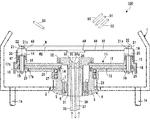
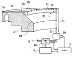
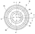
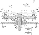
- FIG. 1 is a cross-sectional view showing a schematic configuration of a spin processing apparatus 100 as a substrate processing apparatus to which the present invention is applied.
- This spin processing apparatus 100 has a cup body 1 indicated by a two-dot chain line in FIG.
- a through hole 2 is provided in the central portion in the radial direction of the bottom of the cup body 1, and a plurality of discharge pipes 1 a are connected to the peripheral portion at predetermined intervals in the circumferential direction.
- a cylindrical power transmission body 3 is provided in the through hole 2.
- This power transmission body 3 is rotationally driven by a control motor 4 which is a driving means.
- the control motor 4 includes a cylindrical stator 5 and a similarly cylindrical rotor 6 that is rotatably inserted into the stator 5.
- the lower end of the power transmission body 3 is brought into contact with the upper end surface of the rotor 6, and that portion is fixed by a screw 7. Accordingly, the power transmission body 3 rotates integrally with the rotor 6.
- the rotational speed of the control motor 4 is controlled by the control unit 8 (see FIG. 2).
- a rotary table 11 is attached to the upper end of the power transmission body 3 protruding into the cup body 1.
- the rotary table 11 is formed by overlapping a disk-shaped lower plate 12 and an upper plate 13, and the central portion of the lower plate 12 and the upper plate 13 communicates with the internal space of the power transmission body 3.
- a through hole 14 is formed.
- support cylinder portions 15 are integrally formed at a peripheral portion of the upper plate 13 of the rotary table 11 at a predetermined interval, for example, an interval of 90 degrees in the circumferential direction.
- a through hole 16 is formed in a portion corresponding to the support cylinder portion 15 of the lower plate 12.
- Bushings 17a and 17b are fitted and fitted to the support cylinder portion 15 and the through holes 16, respectively, and holding members 18 are rotatably supported by the bushings 17a and 17b.
- the holding member 18 includes a shaft portion 19 supported by the bushes 17 a and 17 b and a head portion 20 having a larger diameter than the shaft portion 19 formed integrally with the upper end portion of the shaft portion 19.
- a taper member 21 is provided on the upper end surface of the head 20 at a position eccentric from the rotation center of the shaft portion 19.
- An engagement pin 22 projects from the upper end of the taper surface 21a of the taper member 21 in the inclination direction.
- a substrate W such as a semiconductor wafer is provided with the back surface W2 of the peripheral portion placed on the taper surface 21a.
- the taper member 21 rotates eccentrically. Accordingly, the peripheral portion of the substrate W rises along the tapered surface 21 a of the taper member 21, and the outer peripheral surface abuts on the engagement pin 22, so that the substrate W is integrated with the turntable 11 by the four holding members 18. Retained.
- the lower end of the shaft portion 19 of the holding member 18 protrudes to the lower surface side of the rotary table 11, and a slave gear 25 is fixed to the protruding end portion.
- the child gear 25 fixed to the shaft portion 19 of each holding member 18 meshes with the parent gear 26.
- the master gear 26 is rotatably held by the power transmission body 3 via a bearing 27.
- the main gear 26 is urged in a predetermined rotational direction, for example, counterclockwise by a spring 28 provided on the outer peripheral surface of the power transmission body 3.
- a spring 28 provided on the outer peripheral surface of the power transmission body 3.
- the parent gear 26 is rotated clockwise against the urging force of the spring 28 by a release mechanism (not shown). Specifically, the main gear 26 is prevented from rotating by the release mechanism, and the rotary table 11 is rotated counterclockwise by the control motor 4 in this state. Accordingly, since the holding member 18 rotates counterclockwise, the holding state of the substrate W by the engagement pin 22 is released.
- the holding cylinder 31 fixed to the main body of the spin processing apparatus 100 is inserted into the power transmission body 3.
- a nozzle head 32 is attached to the upper end of the holding cylinder 31.
- the nozzle head 32 is formed with a concave portion 30 having an inverted cone shape or a mortar shape (hereinafter represented by an inverted cone shape) having a cross-sectional shape opened on the upper surface. Since the holding cylinder 31 is separated from the power transmission body 3, the nozzle head 32 does not rotate even if the rotary table 11 or the like rotates.
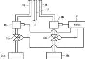
- the nozzle head 32 includes a gas discharge nozzle 33 that discharges a gas such as nitrogen gas toward the center of the back surface W2 of the substrate W held on the turntable 11, and pure water that discharges pure water as a rinsing liquid.
- a chemical solution discharge nozzle 41 (see FIG. 3) is formed with the tip opening on the surface of the recess 30.
- the pure water discharge nozzle 34, the first chemical liquid discharge nozzle 40, and the second chemical liquid discharge nozzle 41 constitute a processing liquid supply nozzle. Further, the nozzle head 32 is formed with a drainage hole 30 a having a tip opened at the lowermost end of the inner surface of the recess 30.
- An air supply pipe 35 is connected to the rear end of the gas discharge nozzle 33, and a pure water supply pipe 36 is connected to the rear end of the pure water discharge nozzle 34. Furthermore, a drainage pipe 37 is connected to the drainage hole 30a, and the drainage hole 30a and the drainage pipe 37 form a drainage part.
- the first chemical liquid supply pipe and the second chemical liquid supply pipe are connected to the rear ends of the first chemical liquid discharge nozzle 40 and the second chemical liquid discharge nozzle 41, respectively. Yes.
- the air supply pipe 35 is connected to a gas supply source 35c that supplies a gas such as nitrogen gas to the gas discharge nozzle 33 via a flow rate adjustment valve 35a and an on-off valve 35b. Accordingly, when the on-off valve 35b is opened, gas is discharged from the gas discharge nozzle 33, and when the on-off valve 35b is closed, gas discharge is stopped.
- the gas flow rate at the time of discharge is set by the flow rate adjusting valve 35a.
- the pure water supply pipe 36 is connected to a rinse liquid supply source 36c that supplies a rinse liquid (pure water or the like) to the pure water discharge nozzle 34 via a flow rate adjustment valve 36a and an on-off valve 36b. Therefore, when the on-off valve 36b is opened, pure water is discharged from the pure water discharge nozzle 34, and when the on-off valve 36b is closed, the discharge of pure water is stopped.
- the flow rate of the rinse liquid at the time of discharge is set by the flow rate adjustment valve 36a.
- the first chemical liquid supply pipe is a supply source for supplying a chemical liquid such as an etching liquid to the first chemical liquid discharge nozzle 40
- the second chemical liquid supply pipe is a second chemical liquid supply pipe.
- a supply source for supplying a chemical solution such as SC-1 solution to the chemical solution discharge nozzle 41 is connected via a flow rate adjusting valve and an on-off valve, respectively.
- the flow regulating valve and opening-closing valve provided in the middle of piping are controlled by the control part 8.
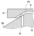
- the upper surface and outer peripheral surface of the rotary table 11 are covered with a cover 45 integral with the rotary table 11.
- the cover 45 includes a facing wall portion 46 that faces the back surface W ⁇ b> 2 of the substrate W held on the turntable 11, and a peripheral wall portion 47 that is provided perpendicular to the peripheral edge portion of the facing wall portion 46.
- a gas such as nitrogen gas discharged from the gas discharge nozzle 33, pure water discharged from the pure water discharge nozzle 34, and chemical liquid discharged from the first and second chemical liquid discharge nozzles 40 and 41 are disposed on the opposing wall portion 46. Is formed in the opening 48 for reaching the back surface W2 of the substrate W.
- the upper end portions of the four holding members 18 provided on the upper surface of the turntable 11 protrude from the through holes 49 provided so as to penetrate the opposing wall portion 46 of the cover 45 to the upper surface side.
- a first upper nozzle body 50 that discharges a chemical solution such as an etching solution to the substrate W and a chemical solution such as an SC-1 solution are discharged above the turntable 11.
- the processing of the substrate W in this embodiment includes an etching process, a chemical solution cleaning process, a rinsing process, and a drying process.
- the operation control is all performed by the control unit 8.
- the control unit 8 includes a microcomputer that centrally controls each unit and a storage unit that stores substrate processing information and various programs related to substrate processing.
- the control unit 8 performs control as follows based on the substrate processing information and various programs.
- the substrate W is held on the turntable 11, and the turntable 11 is held at several tens to several hundreds r. p. Rotate at a low speed of m. While rotating the turntable 11, an etching solution is supplied from the first chemical solution discharge nozzle 40 and the first upper nozzle body 50 to the front surface W1 (upper surface) and the rear surface W2 (lower surface) of the substrate W. The etching solution supplied to the substrate W is directed to the outer peripheral portion of the substrate W by centrifugal force and spreads over the entire surface of the substrate. When the etching process is finished after a predetermined time has elapsed from the start of the supply of the etching solution, the supply of the etching solution is stopped. Next, the SC-1 solution is supplied from the second chemical solution discharge nozzle 41 and the second upper nozzle body 51 to the front surface W1 and the back surface W2 of the substrate W. Thereby, the etching solution remaining on the substrate W is removed.
- the supply of the SC-1 solution is stopped.
- pure water is supplied from the pure water discharge nozzle 34 and the third upper nozzle body 52 to the front surface W1 and the back surface W2 of the substrate W. Thereby, a rinsing process is performed, and the SC-1 solution remaining on the front and back surfaces of the substrate W is removed.
- turn table 11 is several thousand r. p.
- the gas is rotated at a high speed of m, and a gas such as nitrogen gas is blown from the gas discharge nozzle 33 and the fourth upper nozzle 53 to the front surface W1 and the back surface W2 of the substrate W.
- a gas such as nitrogen gas is blown from the gas discharge nozzle 33 and the fourth upper nozzle 53 to the front surface W1 and the back surface W2 of the substrate W.
- the processing liquid remaining on the substrate W is blown off from the front and back surfaces of the substrate W, and a drying process is performed.
- the chemical solution or the rinse solution supplied to the surface W1 of the substrate W is blown outward by the centrifugal force generated by the rotation of the substrate W, and is collected from the discharge pipe 1a after colliding with the inner surface of the cup body 1.
- the chemical solution and the rinsing liquid supplied to the back surface W2 of the substrate W are also blown outward by centrifugal force, but a part of the chemical solution and the rinsing liquid supplied to the back surface W2 is scattered in the concave portion 30, It flows and is discharged from the drainage hole 30a.
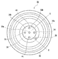
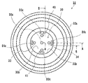
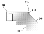
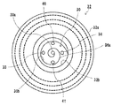
- FIG. 3 is an enlarged plan view showing a state in which the nozzle head 32 constituting the substrate processing apparatus 100 according to the first embodiment is viewed from the substrate W side.
- the outermost line is an outer edge 32 a of the nozzle head 32.
- an inner edge 32b of the nozzle head 32 is also shown on the inside, which is the upper end of the slope 30b of the recess 30.
- a drainage hole 30a provided at the bottom of the recess 30 is shown at the center in FIG. 3 inside the inner edge 32b.
- a gas discharge nozzle 33 that discharges gas toward the back surface W2 is provided on the left side of the drainage hole 30a, and a position facing the gas discharge nozzle 33 across the drainage hole 30a. Is provided with a pure water discharge nozzle 34 for discharging pure water toward the back surface W2.
- a first chemical discharge nozzle 40 that discharges a chemical such as an etching solution is provided above the drain hole 30a, and the SC-1 solution is provided below the drain hole 30a.
- a second chemical liquid discharge nozzle 41 for discharging a chemical liquid such as the above is provided.
- the center lines orthogonal to each other are indicated by a one-dot chain line so as to pass through the center of the drainage hole 30a. All of the four nozzles described above are provided such that their centers are located on the center line.
- the number and arrangement positions of various nozzles are as shown in the plan view of FIG. 3 in the embodiment of the present invention, but the numbers and arrangement positions can be arbitrarily set.
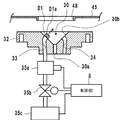
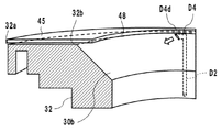
- FIG. 4 is a schematic cross-sectional view showing the configuration of the removal unit D1 according to the first embodiment.
- the removal portion D1 shown in FIG. 4 is represented as “first nozzle D1” for convenience.
- the first nozzle D1 uses the configuration of the gas discharge nozzle 33. Accordingly, the first nozzle D1 also serves to discharge gas to the back surface W2 for promoting drying in the drying process of the back surface W2 that the gas discharge nozzle 33 has.
- the discharge port of the first nozzle D ⁇ b> 1 is configured so that one end thereof protrudes from the inclined surface 30 b of the recess 30. Even if the configuration in which the one end portion of the first nozzle D1 is slightly protruded in this way is employed, if it is ensured that gas is properly discharged to the back surface W2, it may cause a harmful effect on the drying process. Absent.
- a hole D1a is newly provided on one end side of the first nozzle D1 protruding from the inclined surface 30b. Since one end of the first nozzle D1 is provided with a discharge port for discharging gas to the back surface W2, the gas discharged from this discharge port is in the direction indicated by the arrow in FIG. Discharged.
- the position where the hole D1a is provided is a direction orthogonal to the gas discharge direction (the direction of the arrow in FIG. 4) from the discharge port, and the gas is directed toward the recess 30. This is a position where discharge is possible.
- the hole D1a is provided at a position where the opening can be seen from the front.
- the opening diameter of the hole D1a is considered in consideration that the power of the gas discharged in the direction of the arrow for drying from the discharge port toward the back surface W2 does not deteriorate when the gas is discharged from the hole D1a. It is determined.
- the gas discharge nozzle 33 is connected to the gas supply source 35 c via the flow rate adjustment valve 35 a and the on-off valve 35 b.
- the control unit 8 adjusts the discharge amount of the gas discharged from one end of the first nozzle D1 and the gas discharged from the hole D1a of the first nozzle D1 by adjusting the flow rate adjustment valve 35a, and the gas discharge The timing is adjusted by switching the on-off valve 35b.
- the control unit 8 switches the flow rate (flow velocity) of the gas discharged from one end of the first nozzle D1 between at least two different first flow rates and second flow rates.
- the first flow rate means that the gas discharged from one end of the first nozzle D1 does not reach the back surface W2 of the substrate W, but the gas discharged from the hole D1a of the first nozzle D1 is a recess.
- the flow rate is such that it can move spirally or spirally (spirally) in the circumferential direction of the recess 30 along the 30 inclined surfaces 30b.
- the second flow rate is a flow rate sufficient for the gas flow discharged from one end of the first nozzle D1 to dry the back surface W2 of the substrate.
- the first flow rate is much less than the second flow rate.
- the on-off valve 35b is closed until the etching process, the chemical cleaning process, and the rinsing process described above. Then, the opening / closing valve 35b is switched to open until the rinsing process is completed and the drying process is started.
- the on-off valve 35b is switched to open, first, the flow rate of the gas discharged from one end of the first nozzle D1 is set to the first flow rate. Since the recess 30 is formed in an inverted conical shape, the gas discharged from the hole D1a by providing the hole D1a moves along the circumferential direction in the inclined surface 30b of the recess 30. Therefore, the liquid droplets existing in the recess 30 can be moved to the drain hole 30a. That is, in this embodiment, a gas such as nitrogen gas used for drying the substrate functions as a removal material.
- the flow rate of the gas discharged from one end of the first nozzle D1 is switched to the second flow rate.
- the gas of the 2nd flow volume is discharged from the one end part of the 1st nozzle D1 with respect to the back surface W2 of the board
- gas discharge continues from the hole D1a of the first nozzle D1.
- the on-off valve 35b is closed, and gas discharge from the first nozzle D1 and the hole D1a is stopped.
- the liquid droplet is discharged from the hole D1a of the first nozzle D1.
- the inclined surface 30b can be moved by the gas and guided to the drain hole 30a. For this reason, it is possible to prevent inconveniences (occurrence of water stain or the like) such that chemicals adhere to the substrate during the drying process.
- a gas (inert gas or the like) used for promoting the drying of the back surface W2 can be used when removing the droplets existing in the concave portion 30, it is separately used for removing the droplets. It is not necessary to prepare the gas.
- the flow rate of the gas discharged from one end portion of the first nozzle D1 is set to the first flow rate, and the one end portion of the first nozzle D1 is set. From now on, a small amount of gas was discharged. For this reason, in a processing process using a processing liquid such as an etching process, a chemical liquid cleaning process, or a rinsing process, the processing liquid enters one end of the first nozzle D1 or the hole D1a provided in the first nozzle D1. Even if it is, the processing liquid can be removed from both nozzles before the drying process is started. This can also prevent inconveniences such as chemicals adhering to the substrate during the drying process.
- a processing liquid such as an etching process, a chemical liquid cleaning process, or a rinsing process
- the hole D1a shown in FIG. 4 faces the front, and only one is provided. However, a plurality of holes D1a may be provided.
- the first nozzle D1 may be provided with a plurality of holes at different angles toward the inclined surface 30b so that gas can be discharged toward the inclined surface 30b.
- the drying promoting gas is discharged to the back surface W2
- the droplets can be further efficiently removed by discharging the gas over a wide range of the inclined surface 30b.
- FIG. 5 is an enlarged plan view showing a configuration of the removing unit according to the second embodiment as viewed from the substrate side.
- the removal unit D2 uses the gas discharged to the back surface W2 as in the first embodiment, but a second nozzle D2 is provided separately from the gas discharge nozzle 33, and the gas is discharged from the second nozzle D2 into the recess 30. It is made to discharge.
- a second nozzle D2 is formed between the pure water discharge nozzle 34 and the second chemical liquid discharge nozzle 41 in the recess 30.
- the second nozzle D ⁇ b> 2 is a nozzle that discharges gas toward the cover 45.
- a mechanism is adopted in which the direction of the gas discharged toward the cover 45 is changed to guide the gas to the recess 30.
- FIG. 6 is a schematic cross-sectional view showing a piping system cut along line XX in FIG. 5, and FIG. 7 is a partially enlarged view of FIG.
- the second nozzle D2 is formed so as to penetrate the inside of the nozzle head 32, and one end of the second nozzle D2, which is a gas discharge port, is open to the inclined surface 30b.
- the other end of the second nozzle D2 is connected to a gas supply source 35c, and the supplied gas is discharged from one end of the second nozzle D2 toward the cover 45.
- only one second nozzle D2 is provided in the nozzle head 32, but a plurality of second nozzles D2 may be provided.
- the cover 45 is formed with a return 45 a that changes the direction of the gas discharged from the second nozzle D ⁇ b> 2 toward the cover 45 over the entire periphery of the edge of the opening 48.
- the barb 45 a has a shape like an eaves that covers the upper part of the inclined surface 30 b. The gas discharged from the second nozzle D2 hits the return 45a and diffuses.
- the gas discharged from the second nozzle D2 first hits the cover 45.
- the discharged gas hits the region including the return 45a of the cover 45.
- the gas that hits the return 45a diffuses around the return 45a.
- the gas diffused by the return 45a flows along the return 45a, and part of the gas escapes from the gap between the nozzle head 32 and the cover 45 to the outside of the cover 45, but the remaining gas is discharged from the upper part of the inclined surface 30b. It flows toward the hole 30a.
- the droplets existing on the inclined surface 30b can be moved to the drainage hole 30a, and the droplets staying in the recess 30 can be removed.
- the return 45a formed above the second nozzle D2 is formed to diffuse the discharged gas and to change the direction thereof, so that the gas is diffused and the direction is surely changed. ing. Further, as shown in FIG. 5, since the cover 45 is formed in a substantially disk shape, the turn 45a is also formed in a substantially disk shape.
- the second nozzle D2 is connected to a gas supply source 35c via a flow rate adjustment valve 38a and a three-way valve 38b.
- the gas supply source 35 c is a supply source that supplies gas to the gas discharge nozzle 33.
- the three-way valve 38b opens and closes the valve to distribute the gas supplied from the gas supply source 35c to the gas discharge nozzle 33 and the second nozzle D2 that discharge the gas toward the back surface W2 of the substrate.
- control part 8 switches the three-way valve 38b to opening until a rinse process is complete
- FIG. 8 shows the removal portion according to the third embodiment, but it is also possible to form the return 45a only in a part of the opening 48 and not form the return 45a in the other part.
- FIG. 9 shows the removal portion according to the fourth embodiment, but along the periphery of the opening 48, a region where the barbs 45a are clearly formed and a region where the barbs 45a are not formed are provided. Regarding the region located between the two regions, the portion of the return 45a is formed so as to gradually disappear along the circumferential direction of the opening 48.
- the second nozzle when the return 45a is provided only at a part of the peripheral edge of the opening 48, the second nozzle is used in the region where the return 45a is provided as described above.
- the gas discharged from D2 diffuses and a part of the gas moves so as to flow along the circumferential direction on the inclined surface 30b.
- the gas discharged from the second nozzle D2 travels toward the back surface W2 of the substrate W and diffuses on the back surface W2, and part of the gas is spread on the surface of the cover 45. Will reach.
- the gas that has reached the surface of the cover 45 is attracted by the flow of airflow generated between the cover 45 and the substrate W that rotates together, and moves the surface of the cover 45 toward the outer periphery.
- the processing liquid adhering to the surface of the cover 45 when the back surface W2 of the substrate is cleaned is forcibly moved to the outside of the cover 45 to be removed. The degree of cleaning of W2 can be maintained.
- the operation of the three-way valve 38b may be controlled so that the gas discharged from the second nozzle D2 is discharged (intermittent discharge) only when the return 45a is positioned in the discharge direction.
- FIG. 10 is an enlarged plan view showing a state in which the removing unit D3 according to the fifth embodiment is viewed from the substrate W.
- the liquid droplets such as a chemical solution present in the recess 30 are removed using, for example, a liquid such as pure water as a removing material.
- the removal portion D3 that is a discharge port for discharging pure water is provided in an annular shape along the peripheral edge of the recess 30. As shown in the enlarged plan view of FIG. 10, the removal portion D ⁇ b> 3 is annularly arranged along the inner edge 32 b on the upper portion of the recess 30 near the inner edge 32 b of the nozzle head 32. That is, by flowing pure water from the position as high as possible on the inclined surface 30b of the concave portion 30 toward the drain hole 30a, the liquid droplets existing on the inclined surface 30b are surely removed.
- the removal portion D3 is provided to remove droplets present on the inclined surface 30b of the concave portion 30, and as shown in FIG. 11, in order to flow pure water toward the drainage hole 30a along the inclined surface 30b. Moreover, the discharge port of the removal portion D3 is formed to have the same inclination as the inclination of the inclined surface 30b. By ejecting a removing material such as pure water from the removing section D3, it is possible to remove the droplets present in the recess 30.
- FIG. 12 shows a removing material supply passage D3a for supplying the removing material to the removing unit D3.
- the removal material supply passage D3a is formed so as to penetrate through the nozzle head 32, and as shown in FIG. 12, the removal material supply passage D3a is removed at the upper portion of the recess 30 by a removal portion D3 arranged in an annular shape along the inner edge 32b. An annular shape is formed in the nozzle head 32 to supply the material sufficiently.
- the illustration of the pure water discharge nozzle 34 is omitted.
- the removal portion D3 is annularly arranged along the inner edge 32b in the upper portion of the recess 30 near the inner edge 32b of the nozzle head 32. That is, a discharge port is provided between the inner edge 32b and the inclined surface 30b, which is a gap for allowing the removing material to flow out toward the inclined surface 30b, from which the removing material is discharged. That is, the gap corresponds to the removal portion D3.
- the removal material supply passage D3a is also formed in an annular shape so as to supply the removal material to all the removal portions D3.
- the pure water that has flowed out from the entire circumferential direction of the concave portion 30 by the removing portion D3 is transmitted along the inclined surface 30b and linearly flows down toward the drainage hole 30a as shown by the arrow in FIG. For this reason, the droplet which exists in the recessed part 30, ie, the slope 30b, can be removed using the pure water which flows down the slope 30b.
- FIG. 13 is a schematic perspective view corresponding to FIG. 12 and showing a removal portion D3 according to the sixth embodiment.
- the difference from the removal portion D3 shown in FIG. 12 is that the eaves D3b is provided at the inner edge 32b of the nozzle head 32.
- the removal portion D3 shown in FIG. 13 also discharges a removal material (such as pure water) from the discharge port, which is a gap provided between the inner edge 32b of the nozzle head 32 and the inclined surface 30b, toward the inclined surface 30b.
- a removal material such as pure water
- the eaves D3b it is possible to use not only liquid but also gas as a removing material used for removing the droplets existing on the inclined surface 30b. That is, the gas discharged from the removal part D3 hits the eaves D3b and is blown toward the inclined surface 30b.
- the eaves D3b By providing the eaves D3b in this way, the direction of the removal material discharged from the discharge port can be forcibly changed. Therefore, even if the removal material is a gas, the gas discharged from the discharge port is diffused. It can guide to slope 30b, without doing.
- FIG. 14 is an enlarged plan view showing a configuration of the removing unit D3c according to the seventh embodiment viewed from the substrate W side.
- a plurality of discharge ports are provided along the periphery of the inclined surface 30b. The removal material is discharged from each discharge port.
- a removal portion D3c having four discharge ports is provided.
- Each of the four removal portions D3c is provided above the processing liquid discharge nozzle. Further, these removing portions D3c are provided on lines connecting the center of the drainage hole 30a and, for example, the centers of the first chemical liquid discharge nozzle 40 and the second chemical liquid discharge nozzle 41, respectively.
- the removal unit D3c By providing the removal unit D3c at such a position, for example, the chemical liquid discharged from the first chemical liquid discharge nozzle 40 or the second chemical liquid discharge nozzle 41, and the liquid droplets staying in the vicinity of these discharge nozzles can be obtained. It can be reliably cleaned and removed.
- the number of discharge ports (removal portions D3c) can be arbitrarily set.
- the discharge angle of the removal material discharged from each discharge port (removal part D3c) can also be set arbitrarily. For example, the angle may be set so that the removal material can be discharged at a wide angle.
- a gas can be discharged from the removing unit D3c.
- the removing material is discharged from the discharge ports of the plurality of removing portions D3c provided, the removing material is caused to flow toward the drain hole 30a along the inclined surface 30b, and the liquid droplets existing in the recess 30 are drained. Can be removed.
- FIG. 15 is an enlarged plan view showing a configuration of the removing unit D4 according to the eighth embodiment as viewed from the substrate W side
- FIG. 16 is a schematic partial enlarged view taken along line CC in FIG. It is sectional drawing.
- the removal portion D4 is composed of a nozzle D4a having a circular cross section, and is formed in an upper portion of the recess 30 near the inner edge 32b of the nozzle head 32 in such a direction that the discharge port is substantially parallel to the inclined surface 30b. That is, the discharge port is arranged so as to face the circumferential direction of the inclined surface 30b.
- the removal material when the removal material is discharged from the nozzle D4a, the removal material flows in a spiral shape (spiral shape) on the inclined surface 30b and reaches the drainage hole 30a as shown by an arrow in FIG. Since the removing material spirally flows on the inclined surface 30b, the removing material flows exhaustively on the inclined surface 30b, so that all the liquid droplets existing in the concave portion 30 can be removed.
- FIG. 17 is a schematic partial enlarged cross-sectional view corresponding to FIG. 16 and showing a removal portion D4 according to the ninth embodiment.
- the removal portion D4 is configured as an opening D4b that discharges the removal material, and is formed directly on the inclined surface 30b.
- the opening D4b which comprises the removal part D4 is provided so that it may face the circumferential direction of the slope 30b so that a removal material may flow in parallel with the circumferential direction of the slope 30b at the time of discharge of a removal material.
- the front side of the discharge port of the opening D4b is shown, and the shape of the discharge port is substantially triangular.
- the removal material discharged from the nozzle is made to flow spirally on the inclined surface 30b using the discharge force, but is discharged from the nozzle or opening.
- a guide groove D4c is provided to allow the removed material to flow more spirally on the inclined surface 30b.
- FIG. 18 is an enlarged plan view showing a configuration of the removing unit D4 according to the tenth embodiment as viewed from the substrate W side
- FIG. 19 is a schematic perspective view cut along the line DD in FIG. .
- the pure water discharge nozzle 34 and the first chemical liquid discharge nozzle 40 are omitted.
- This embodiment differs from the eighth embodiment described with reference to FIG. 15 in that the guide groove D4c is curved along the slope 30b from the opening through which the removal material is discharged in the removal portion D4. Is a point provided.
- the guide groove D4c is formed over a certain distance from the opening through which the removal material is discharged.
- the starting point of the guide groove D4c is the top of the pure water discharge nozzle 34.
- the guide groove D4c is formed in a curved shape along the circumferential direction of the inclined surface 30b from this starting point, and is formed up to an upper portion of the first chemical liquid discharge nozzle 40.
- the removal material such as pure water discharged from the removal portion D4 is guided to the guide groove D4c immediately after discharge, flows on the inclined surface 30b, and reaches the end point of the guide groove D4c in front of the first chemical liquid discharge nozzle 40.
- the slope 30b descends spirally and flows toward the drainage hole 30a while entraining the droplets present on the slope 30b. Due to the flow of the removing material, the liquid droplets existing in the recess 30 can be drained and removed.
- the guide groove D4c is formed with a constant groove width from the start point to the end point.
- FIG. 20 shows a configuration of the removal unit D4 according to the eleventh embodiment, and corresponds to FIG.
- the width at the end point is formed wider than the width at the start point in the guide groove D4c. That is, by forming the width of the guide groove D4c so as to gradually increase from the start point to the end point, the removal material such as pure water flowing through the guide groove D4c gradually moves toward the drainage hole 30a. Therefore, the discharged removal material can flow more naturally in a spiral shape.
- the guide groove D4c may be formed so as to make one turn around the inclined surface 30b, and the end thereof may be provided, for example, behind the removal portion D4 or to the lower part. Further, the formation angle of the guide groove D4c, that is, the angle from the start point to the end point can be arbitrarily set.
- FIG. 21 is an enlarged plan view showing a configuration of the removing unit D4 according to the twelfth embodiment as viewed from the substrate W side.
- the removal portion D4 shown in FIGS. 16 and 17 is provided at a position where it does not protrude from the surface of the slope 30b.
- the discharge port D4d constituting the removal portion D4 is formed so as to protrude on the inclined surface 30b.
- the discharge port D4d is formed so as to jump out greatly on the inclined surface 30b, it may cause the liquid droplets to stay in the discharge port D4d. Therefore, as shown in FIG. It is formed to such an extent that it can be raised. With such a shape, even if formed on the inclined surface 30b, for example, even if a liquid splash occurs on the inclined surface 30b, it is possible to avoid droplets from adhering to the discharge port D4d.
- FIG. 23 is a schematic perspective view showing the configuration of the removal unit D4 according to the thirteenth embodiment.
- FIG. 22 is a schematic perspective view corresponding to a view taken along line FF in FIG.
- the discharge port D4d is formed on the inclined surface 30b, and the discharge port D4d is formed so that the opening thereof is not parallel to the inclined surface 30b and slightly faces the lower surface of the inclined surface 30b.
- the removal material discharged from the discharge port D4d is discharged obliquely, that is, slightly below the inclined surface 30b immediately after discharge, as indicated by the arrow in FIG.
- the discharge port D4d By forming the discharge port D4d at an angle in this way, the removal material can be made to flow more spirally.
- the above-described guide groove D4c can be formed in the discharge port D4d.
- any number of the removal portions D4 may be formed on the inclined surface 30b, for example, four portions may be formed on the inclined surface 30b at intervals of 90 degrees.
- the guide groove D4c may be appropriately combined, and the length and width of the guide groove D4c can be freely set.
- path D3a for supplying a removal material to the removal parts D3 and D4 is provided.
- FIG. 24 is a cross-sectional view showing a schematic configuration of the substrate processing apparatus according to the fourteenth embodiment.
- the substrate processing apparatus 100A includes a vibrating unit 60.
- the vibration unit 60 is connected to the nozzle head 32, and applies vibration to the nozzle head 32 based on control from the control unit 8.
- vibration unit 60 for example, an ultrasonic vibration device can be employed.
- the application of ultrasonic vibration to the nozzle head 32 is started before the rinsing process is completed and the drying process is started, and the stage of the drying process is continued. And the provision of ultrasonic vibration is stopped with the completion
- the application of ultrasonic vibration to the nozzle head 32 may be started from the beginning of the etching process and continued until the end of the drying process. In short, it is only necessary that the period of vibration application exists in the period from the end of the rinsing step to the start of the drying step.
- FIG. 25 is a cross-sectional view showing a schematic configuration of a substrate processing apparatus 100B according to the fifteenth embodiment.
- the substrate processing apparatus 100B includes a heating unit 70.
- the heating unit 70 heats the entire nozzle head 32. By heating the nozzle head 32, the droplets present in the recess 30 are evaporated and removed.
- the process of heating the nozzle head 32 using the heating unit 70 and evaporating the droplets existing in the recess 30 is not performed while the substrate W is placed on the holding member 18. This is because if the droplets present in the recess 30 evaporate and adhere to the back surface W2 or the like of the substrate W, water stain due to redeposition may occur.
- the heating unit for example, a method of heating the nozzle head 32 (concave portion 30) by irradiating light such as a halogen lamp from the upper portion of the concave portion 30 is also conceivable.
- the recess 30 is heated from the upper position (facing the recess 30) that is not blocked by the substrate W. By doing so, the droplets are evaporated.
- any means can be used as long as the nozzle head 32 can be heated and the droplets can be evaporated by heating the nozzle head 32 by irradiating light from the upper part of the recess 30 or using an electric heater. Further, the installation position of the heating unit 70 is not limited.
- FIG. 26 is a sectional view showing a schematic configuration of the substrate processing apparatus 100c according to the sixteenth embodiment.
- a substrate processing apparatus 100 ⁇ / b> C illustrated in FIG. 26 includes a suction unit 80.
- the suction unit 80 is connected to a drainage hole 30a provided at the bottom of the recess 30 and sucks a liquid droplet drained into the drainage hole 30a.
- the suction unit 80 is a device that forcibly drains the liquid droplets out of the recess 30, and is connected to the drainage hole 30 a via the drainage pipe 37.
- the suction unit 80 is also connected to the control unit 8 and is driven based on a control signal from the control unit 8.
- a gas such as air or nitrogen may be used to drive the suction unit 80, and a flow meter and an air operation valve may be provided to perform flow rate management.
- the drain hole 30a by applying a suction force to the drain hole 30a, it is possible to forcibly drain the liquid staying in the recess 30 and the liquid droplets that are about to adhere to the recess outside the recess. It is possible to prevent poor drying due to droplets staying on the surface of the recess 30.
- FIG. 27 is an enlarged plan view showing a configuration of the removing unit D5 according to the seventeenth embodiment as viewed from the substrate W side.
- the basic configuration of the substrate processing apparatus 100 is the same as that described above.
- a groove D5a which is a removal portion is formed along the slope 30b so as to connect the inner edge 32b which is the upper end of the slope 30b and the drain hole 30a with the shortest distance.
- 16 grooves D5a are provided at equal intervals around the inner edge 32b.
- the number of the grooves D5a is too small, it is difficult to properly guide the liquid droplets that try to stay on the inclined surface 30b to the drain hole 30a, while the number of the grooves D5 is too large and the width of the grooves becomes small. It is considered that the droplets cannot be properly flowed even if the amount is too large. Accordingly, the number of grooves D5a to be provided on the inclined surface 30b is appropriately determined in consideration of the size and depth of the grooves.
- the groove D5a When the groove D5a is formed by connecting the inner edge 32b, which is the upper end of the inclined surface 30b, and the drainage hole 30a at the shortest distance, the gas discharge nozzle 33, the pure water discharge nozzle 34, the first chemical liquid are provided in the middle of the groove D5a. There may be a discharge nozzle 40 and a second chemical liquid discharge nozzle 41. As for the groove D5a, as shown in FIG. 27, it is preferable that the groove D5a is not formed in a region connecting the inner edge 32b and each nozzle such as the gas discharge nozzle 33. This is to prevent the liquid droplets flowing through the groove D5a from entering each nozzle such as the gas discharge nozzle 33.
- the groove D5a is configured such that the boundary with the surface of the inclined surface 30b does not form a corner but draws a gentle curved surface and is continuous. That is, when this portion is formed with a corner, the force of adhering to the inclined surface 30b becomes strong due to the surface tension of the droplet, it is difficult to enter the groove D5a, and the droplet is transferred to the drainage hole 30a through the groove D5a. Can be difficult to guide. Furthermore, it is preferable that the groove D5a itself is similarly formed of a curved surface.
- FIG. 28 is an enlarged plan view showing a configuration of the removing unit D6 according to the eighteenth embodiment as viewed from the substrate W side.
- the groove D6a constituting the removal portion D6 is formed in a spiral shape (spiral shape in plan view in FIG. 28) on the inclined surface 30b from the inner edge 32b, which is the upper portion of the concave portion 30, toward the drainage hole 30a. Moreover, the groove
- the boundary between the inclined surface 30b and the groove D6a and the groove D6a itself are both formed with a curved surface, as in the case of the groove D5a.
- the spiral direction of the groove D6a is formed counterclockwise from the inner edge 32b toward the drain hole 30a. This is the same direction as the rotation direction of the substrate W when various processes are performed on the substrate W placed above the nozzle head 32.
- the spiral direction of the groove D6a in the same direction as the rotation direction of the substrate W, the droplets existing in the concave portion 30 are moved using the airflow generated along with the counterclockwise rotation of the substrate W. Because you can.
- a configuration in which the surface of the inclined surface 30b of the nozzle head 32 is formed to be rough can be employed. That is, in forming the inclined surface 30b, the surface roughness Ra can be set to a predetermined value, and the inclined surface 30b having a desired surface roughness can be formed.
- liquid droplets exist together on the inclined surface 30b due to surface tension, for example, when gas is discharged from the gas discharge nozzle 33, particularly when the nozzle head 32 is formed of a hydrophobic material,
- the gas causes a phenomenon that the liquid droplet splashes or flies in the recess 30, and the splashed liquid droplet adheres to the back surface W ⁇ b> 2 of the substrate W, for example, leading to water stain due to redeposition.
- the surface of the inclined surface 30b is formed to be as rough as possible so that the droplets existing on the inclined surface 30b are not collected by the surface tension, so that the liquid droplets existing on the inclined surface 30b are not collected by the surface tension. It becomes possible to flow into the hole 30a.
- the setting of the surface roughness Ra can be arbitrarily set according to the material of the nozzle head 32.
- the nozzle head 32 is formed of a hydrophilic material.
- the hydrophilic surface is roughened, the contact angle of the liquid droplet is reduced, so that the hydrophilicity of the liquid droplet to the nozzle head 32 is increased.
- the hydrophilicity is increased, when the droplet adheres to the inclined surface 30b, the droplet easily sticks to the inclined surface 30b. Accordingly, it is possible to prevent the droplets from being scattered.
- the nozzle head 32 is formed of a hydrophobic material
- the surface of the inclined surface 30b is formed rough
- the contact angle of the droplet with respect to the inclined surface 30b increases, so that the droplets more easily flow on the inclined surface 30b.
- the gas is jetted toward the inclined surface 30b to the extent that liquid splash does not occur, so that the liquid droplets are smoothly scattered toward the drain hole 30a while suppressing the scattering of the droplets. It becomes possible to flow droplets.
- the method of roughening the surface of the inclined surface 30b is adopted as described above. can do.
- the heating unit 70 described in the fifteenth embodiment can be used.
- the droplets may be possible to prevent the droplets from being collected by the surface tension by heating the entire nozzle head 32 using the heating unit 70 and increasing the surface temperature of the inclined surface 30b.
- the surface of the inclined surface 30b is maintained at a high temperature, and the droplets themselves are evaporated, whereby the back surface W2 of the substrate W.
- the liquid droplets are prevented from being scattered and the liquid droplets are prevented from being collected so as to flow into the drain hole 30a. Even if such a configuration is adopted, the droplets present in the recess 30 can be removed.
- the nozzle head 32 is formed of a porous material, and droplets existing on the inclined surface 30b are taken into the inclined surface 30b, that is, into the nozzle head 32.
- the liquid droplets existing in the concave portion 30 cannot be dealt with only by flowing into the drainage hole 30a, the liquid droplets are absorbed from the surface of the inclined surface 30b. Drops can be removed.
- the entire nozzle head 32 is not formed of a porous material, but, for example, a material having a porous property is applied to the inclined surface 30b, and droplets existing on the inclined surface 30b are taken into the applied material. Such an embodiment is also conceivable.
- the substrate processing apparatus which can be provided can be provided.
- a liquid removing material such as pure water is used to wash away the liquid droplets present in the concave portion 30, and then a gas removing material is sprayed onto the concave portion 30, whereby residual liquid droplets and removing material are removed.
- the liquid is led to the drainage hole 30a.
- the suction unit 80 to suck out the liquid droplets from the recess 30 and providing the grooves D5a and the grooves D6a on the inclined surface 30b, the liquid droplets are more reliably combined with a configuration in which no liquid droplets remain on the inclined surface. May be removed.
- the removal material discharge start timing and suction force application start timing may be between the end of the rinsing process and the start of the drying process, or a stage before the rinsing process ends, for example, a rinsing process. It may be set to the middle or the initial stage of the etching process.
- end timing of the discharge and suction it may be before the drying process is started, or during the drying process, the discharge or suction is continued, during the drying process, at the end of the drying process, or when the drying process is completed. You may make it stop after it complete
- the stage before the drying process is started.
- the treatment liquid such as the chemical liquid that has entered the nozzles is removed to prevent the problem that the chemical liquid adheres to the substrate during the drying process.
- this discharge may be started from a stage before the rinsing process is completed.
- the gas discharge may be started during the rinsing process, or may be started from the initial stage of the etching process.
- the gas discharge is started from the initial stage of the etching process, it is possible to prevent the chemical solution from entering the gas discharge nozzle itself, and therefore, after the rinsing process is completed, the process can proceed to the drying process without waiting time. In addition, it is possible to prevent inconveniences such as chemicals adhering to the substrate during the drying process.
- the removal material discharged from the removal unit D is a liquid
- the removal material enters the gas discharge nozzle, or the removal unit D removes the removal material that has entered the gas discharge nozzle from the nozzle. It is preferable that the gas is discharged from the gas discharge nozzle 33 at the first flow rate while the removing material is being discharged or after the discharge is completed.
- processing contents of the substrate the example of performing a series of processes of an etching process, a chemical solution cleaning process, a rinsing process, and a drying process has been described, but the present invention can be applied if processing using a processing liquid is included. Is possible.
- the present invention is used in a substrate processing apparatus.
Landscapes
- Engineering & Computer Science (AREA)
- Microelectronics & Electronic Packaging (AREA)
- Condensed Matter Physics & Semiconductors (AREA)
- General Physics & Mathematics (AREA)
- Manufacturing & Machinery (AREA)
- Computer Hardware Design (AREA)
- Physics & Mathematics (AREA)
- Power Engineering (AREA)
- Chemical & Material Sciences (AREA)
- Chemical Kinetics & Catalysis (AREA)
- General Chemical & Material Sciences (AREA)
- Cleaning Or Drying Semiconductors (AREA)
- Weting (AREA)
- Cleaning By Liquid Or Steam (AREA)
- Exposure Of Semiconductors, Excluding Electron Or Ion Beam Exposure (AREA)
Priority Applications (8)
| Application Number | Priority Date | Filing Date | Title |
|---|---|---|---|
| CN202110617130.XA CN113363187B (zh) | 2014-09-30 | 2015-09-30 | 基板处理装置 |
| KR1020177010936A KR102391753B1 (ko) | 2014-09-30 | 2015-09-30 | 기판 처리 장치 |
| JP2016552130A JP6625058B2 (ja) | 2014-09-30 | 2015-09-30 | 基板処理装置 |
| US15/512,308 US10607863B2 (en) | 2014-09-30 | 2015-09-30 | Substrate processing apparatus |
| KR1020227013577A KR102404961B1 (ko) | 2014-09-30 | 2015-09-30 | 기판 처리 장치 |
| CN201580053001.5A CN106716605B (zh) | 2014-09-30 | 2015-09-30 | 基板处理装置 |
| US16/730,661 US20200135504A1 (en) | 2014-09-30 | 2019-12-30 | Substrate processing apparatus |
| US16/730,706 US20200135505A1 (en) | 2014-09-30 | 2019-12-30 | Substrate processing apparatus |
Applications Claiming Priority (2)
| Application Number | Priority Date | Filing Date | Title |
|---|---|---|---|
| JP2014201917 | 2014-09-30 | ||
| JP2014-201917 | 2014-09-30 |
Related Child Applications (3)
| Application Number | Title | Priority Date | Filing Date |
|---|---|---|---|
| US15/512,308 A-371-Of-International US10607863B2 (en) | 2014-09-30 | 2015-09-30 | Substrate processing apparatus |
| US16/730,661 Continuation US20200135504A1 (en) | 2014-09-30 | 2019-12-30 | Substrate processing apparatus |
| US16/730,706 Continuation US20200135505A1 (en) | 2014-09-30 | 2019-12-30 | Substrate processing apparatus |
Publications (1)
| Publication Number | Publication Date |
|---|---|
| WO2016052642A1 true WO2016052642A1 (ja) | 2016-04-07 |
Family
ID=55630666
Family Applications (1)
| Application Number | Title | Priority Date | Filing Date |
|---|---|---|---|
| PCT/JP2015/077790 Ceased WO2016052642A1 (ja) | 2014-09-30 | 2015-09-30 | 基板処理装置 |
Country Status (6)
| Country | Link |
|---|---|
| US (3) | US10607863B2 (enExample) |
| JP (3) | JP6625058B2 (enExample) |
| KR (2) | KR102391753B1 (enExample) |
| CN (2) | CN106716605B (enExample) |
| TW (1) | TWI585842B (enExample) |
| WO (1) | WO2016052642A1 (enExample) |
Cited By (4)
| Publication number | Priority date | Publication date | Assignee | Title |
|---|---|---|---|---|
| JP2018093146A (ja) * | 2016-12-07 | 2018-06-14 | 東京エレクトロン株式会社 | 基板処理装置、基板処理方法及び記憶媒体 |
| CN108417510A (zh) * | 2017-02-09 | 2018-08-17 | 东京毅力科创株式会社 | 液体处理装置 |
| CN113409699A (zh) * | 2020-03-16 | 2021-09-17 | 重庆康佳光电技术研究院有限公司 | 一种便于修复的led显示器及其修复方法 |
| WO2022244394A1 (ja) * | 2021-05-21 | 2022-11-24 | 株式会社Sumco | 半導体ウェーハの洗浄装置、半導体ウェーハの洗浄方法およびシリコンウェーハの製造方法 |
Families Citing this family (9)
| Publication number | Priority date | Publication date | Assignee | Title |
|---|---|---|---|---|
| TWI622091B (zh) * | 2015-06-18 | 2018-04-21 | 思可林集團股份有限公司 | 基板處理裝置 |
| CN109056085A (zh) * | 2018-08-01 | 2018-12-21 | 南通纺织丝绸产业技术研究院 | 熔喷喷嘴结构 |
| JP7221657B2 (ja) * | 2018-11-12 | 2023-02-14 | キオクシア株式会社 | 基板処理装置 |
| JP7634405B2 (ja) * | 2021-03-30 | 2025-02-21 | 芝浦メカトロニクス株式会社 | 基板処理装置 |
| JP7584361B2 (ja) * | 2021-06-17 | 2024-11-15 | 株式会社荏原製作所 | 基板洗浄装置、基板処理装置 |
| KR102535766B1 (ko) * | 2021-08-24 | 2023-05-26 | (주)디바이스이엔지 | 백 노즐 어셈블리를 포함하는 기판 처리장치 |
| EP4489064A1 (en) * | 2023-07-03 | 2025-01-08 | Unity Semiconductor | Substrate dimension adapter |
| CN118925962B (zh) * | 2024-10-12 | 2025-02-28 | 浙江丽水中欣晶圆半导体科技有限公司 | 一种用于洗净机上并具有彻底清洁的喷头 |
| CN119650464A (zh) * | 2024-12-02 | 2025-03-18 | 西安奕斯伟材料科技股份有限公司 | 硅片清洗系统 |
Citations (6)
| Publication number | Priority date | Publication date | Assignee | Title |
|---|---|---|---|---|
| JP2001096238A (ja) * | 1999-07-26 | 2001-04-10 | Tokyo Electron Ltd | 基板洗浄具,基板洗浄装置及び基板洗浄方法 |
| JP2005217138A (ja) * | 2004-01-29 | 2005-08-11 | Shibaura Mechatronics Corp | スピン処理装置及びスピン処理方法 |
| JP2005243940A (ja) * | 2004-02-26 | 2005-09-08 | Dainippon Screen Mfg Co Ltd | 基板処理装置および基板処理方法 |
| JP2010186859A (ja) * | 2009-02-12 | 2010-08-26 | Tokyo Electron Ltd | 液処理装置および液処理方法 |
| JP2010219119A (ja) * | 2009-03-13 | 2010-09-30 | Shibaura Mechatronics Corp | 基板処理装置および基板処理方法 |
| JP2013211377A (ja) * | 2012-03-30 | 2013-10-10 | Dainippon Screen Mfg Co Ltd | 基板処理装置および基板処理方法 |
Family Cites Families (20)
| Publication number | Priority date | Publication date | Assignee | Title |
|---|---|---|---|---|
| JPS61178187U (enExample) * | 1985-04-26 | 1986-11-06 | ||
| JPH07105336B2 (ja) * | 1992-08-27 | 1995-11-13 | 日本電気株式会社 | レジスト現像方法 |
| US5960555A (en) * | 1996-07-24 | 1999-10-05 | Applied Materials, Inc. | Method and apparatus for purging the back side of a substrate during chemical vapor processing |
| KR100613919B1 (ko) | 1999-07-26 | 2006-08-18 | 동경 엘렉트론 주식회사 | 기판세정구, 기판세정장치 및 기판세정방법 |
| JP4327304B2 (ja) * | 1999-07-27 | 2009-09-09 | 芝浦メカトロニクス株式会社 | スピン処理装置 |
| JP3535053B2 (ja) * | 1999-09-09 | 2004-06-07 | 東京エレクトロン株式会社 | 現像処理装置及び現像処理方法 |
| JP3802446B2 (ja) * | 2002-05-15 | 2006-07-26 | 東邦化成株式会社 | 基板乾燥方法およびその装置 |
| US20070132976A1 (en) * | 2005-03-31 | 2007-06-14 | Nikon Corporation | Exposure apparatus, exposure method, and method for producing device |
| JP4627681B2 (ja) * | 2005-04-20 | 2011-02-09 | 芝浦メカトロニクス株式会社 | 基板の処理装置及び処理方法 |
| JP4734063B2 (ja) * | 2005-08-30 | 2011-07-27 | 東京エレクトロン株式会社 | 基板洗浄装置及び基板洗浄方法。 |
| CN101165854A (zh) * | 2006-10-19 | 2008-04-23 | 大日本网目版制造株式会社 | 基板处理装置和基板处理方法 |
| JP4774004B2 (ja) | 2007-03-30 | 2011-09-14 | 富士フイルム株式会社 | ウエブ状被洗浄物の洗浄方法及び装置 |
| JP5249915B2 (ja) * | 2009-01-22 | 2013-07-31 | 東京エレクトロン株式会社 | 薬液処理装置および薬液処理方法 |
| JP3155351U (ja) * | 2009-09-02 | 2009-11-12 | 東京エレクトロン株式会社 | 液処理装置 |
| JP4927158B2 (ja) * | 2009-12-25 | 2012-05-09 | 東京エレクトロン株式会社 | 基板処理方法、その基板処理方法を実行させるためのプログラムを記録した記録媒体及び基板処理装置 |
| JP5440441B2 (ja) * | 2010-08-12 | 2014-03-12 | 東京エレクトロン株式会社 | 液処理装置 |
| JP6046417B2 (ja) * | 2012-08-17 | 2016-12-14 | 株式会社Screenホールディングス | 基板処理装置、および基板処理方法 |
| JP6017262B2 (ja) * | 2012-10-25 | 2016-10-26 | 東京エレクトロン株式会社 | 基板処理装置および基板処理方法 |
| JP5951444B2 (ja) * | 2012-10-25 | 2016-07-13 | 東京エレクトロン株式会社 | 基板処理装置および基板処理方法 |
| JP6319941B2 (ja) * | 2013-03-15 | 2018-05-09 | 株式会社Screenホールディングス | 基板処理装置および吐出ヘッド待機方法 |
-
2015
- 2015-09-30 TW TW104132199A patent/TWI585842B/zh active
- 2015-09-30 KR KR1020177010936A patent/KR102391753B1/ko active Active
- 2015-09-30 WO PCT/JP2015/077790 patent/WO2016052642A1/ja not_active Ceased
- 2015-09-30 US US15/512,308 patent/US10607863B2/en active Active
- 2015-09-30 CN CN201580053001.5A patent/CN106716605B/zh active Active
- 2015-09-30 KR KR1020227013577A patent/KR102404961B1/ko active Active
- 2015-09-30 CN CN202110617130.XA patent/CN113363187B/zh active Active
- 2015-09-30 JP JP2016552130A patent/JP6625058B2/ja active Active
-
2019
- 2019-07-04 JP JP2019125068A patent/JP6761081B2/ja active Active
- 2019-11-05 JP JP2019200987A patent/JP6804622B2/ja active Active
- 2019-12-30 US US16/730,706 patent/US20200135505A1/en not_active Abandoned
- 2019-12-30 US US16/730,661 patent/US20200135504A1/en not_active Abandoned
Patent Citations (6)
| Publication number | Priority date | Publication date | Assignee | Title |
|---|---|---|---|---|
| JP2001096238A (ja) * | 1999-07-26 | 2001-04-10 | Tokyo Electron Ltd | 基板洗浄具,基板洗浄装置及び基板洗浄方法 |
| JP2005217138A (ja) * | 2004-01-29 | 2005-08-11 | Shibaura Mechatronics Corp | スピン処理装置及びスピン処理方法 |
| JP2005243940A (ja) * | 2004-02-26 | 2005-09-08 | Dainippon Screen Mfg Co Ltd | 基板処理装置および基板処理方法 |
| JP2010186859A (ja) * | 2009-02-12 | 2010-08-26 | Tokyo Electron Ltd | 液処理装置および液処理方法 |
| JP2010219119A (ja) * | 2009-03-13 | 2010-09-30 | Shibaura Mechatronics Corp | 基板処理装置および基板処理方法 |
| JP2013211377A (ja) * | 2012-03-30 | 2013-10-10 | Dainippon Screen Mfg Co Ltd | 基板処理装置および基板処理方法 |
Cited By (7)
| Publication number | Priority date | Publication date | Assignee | Title |
|---|---|---|---|---|
| JP2018093146A (ja) * | 2016-12-07 | 2018-06-14 | 東京エレクトロン株式会社 | 基板処理装置、基板処理方法及び記憶媒体 |
| CN108417510A (zh) * | 2017-02-09 | 2018-08-17 | 东京毅力科创株式会社 | 液体处理装置 |
| US11322373B2 (en) * | 2017-02-09 | 2022-05-03 | Tokyo Electron Limited | Liquid processing apparatus |
| CN113409699A (zh) * | 2020-03-16 | 2021-09-17 | 重庆康佳光电技术研究院有限公司 | 一种便于修复的led显示器及其修复方法 |
| WO2022244394A1 (ja) * | 2021-05-21 | 2022-11-24 | 株式会社Sumco | 半導体ウェーハの洗浄装置、半導体ウェーハの洗浄方法およびシリコンウェーハの製造方法 |
| JP2022179202A (ja) * | 2021-05-21 | 2022-12-02 | 株式会社Sumco | 半導体ウェーハの洗浄装置、半導体ウェーハの洗浄方法およびシリコンウェーハの製造方法 |
| JP7556328B2 (ja) | 2021-05-21 | 2024-09-26 | 株式会社Sumco | 半導体ウェーハの洗浄装置、半導体ウェーハの洗浄方法およびシリコンウェーハの製造方法 |
Also Published As
| Publication number | Publication date |
|---|---|
| JP6761081B2 (ja) | 2020-09-23 |
| CN113363187A (zh) | 2021-09-07 |
| JPWO2016052642A1 (ja) | 2017-07-13 |
| CN113363187B (zh) | 2024-03-22 |
| US20200135505A1 (en) | 2020-04-30 |
| TW201633392A (zh) | 2016-09-16 |
| KR20170063779A (ko) | 2017-06-08 |
| JP2020074395A (ja) | 2020-05-14 |
| CN106716605A (zh) | 2017-05-24 |
| KR102404961B1 (ko) | 2022-06-07 |
| TWI585842B (zh) | 2017-06-01 |
| CN106716605B (zh) | 2021-06-08 |
| JP6625058B2 (ja) | 2019-12-25 |
| JP2019186565A (ja) | 2019-10-24 |
| US20170278729A1 (en) | 2017-09-28 |
| KR20220054469A (ko) | 2022-05-02 |
| KR102391753B1 (ko) | 2022-04-28 |
| US10607863B2 (en) | 2020-03-31 |
| US20200135504A1 (en) | 2020-04-30 |
| JP6804622B2 (ja) | 2020-12-23 |
Similar Documents
| Publication | Publication Date | Title |
|---|---|---|
| JP2019186565A (ja) | 基板処理装置 | |
| JP3420900B2 (ja) | 塗布液塗布方法 | |
| US20140261570A1 (en) | Substrate liquid processing method, substrate liquid processing apparatus, and storage medium | |
| KR20120033243A (ko) | 기판처리장치 및 기판처리방법 | |
| JP6027465B2 (ja) | 基板処理装置及び基板処理方法 | |
| TW202214358A (zh) | 基板處理方法及基板處理裝置 | |
| JP7236318B2 (ja) | 液処理装置、及び液処理方法 | |
| JP6502050B2 (ja) | 基板処理装置および基板処理方法 | |
| JPH10151406A (ja) | 塗布液塗布方法 | |
| JP4364659B2 (ja) | スピン処理装置及びスピン処理方法 | |
| TWI406108B (zh) | 顯影裝置及顯影方法 | |
| JP2011199012A (ja) | 半導体装置の製造方法 | |
| JP7598821B2 (ja) | 塗布処理方法および塗布処理装置 | |
| JP2007048814A (ja) | 基板保持装置、半導体製造装置及び半導体装置の製造方法 | |
| JP6465744B2 (ja) | 基板処理装置および基板処理方法 | |
| JP2003022997A (ja) | スピン処理装置及び処理方法 | |
| JPH10151407A (ja) | 塗布液塗布方法 | |
| JP2007115775A (ja) | 半導体ウェハの洗浄装置及び半導体ウェハの洗浄方法 | |
| TW202224784A (zh) | 基板處理裝置及基板處理方法 | |
| JP2014157984A (ja) | 回転塗布装置および回転塗布装置の洗浄方法 |
Legal Events
| Date | Code | Title | Description |
|---|---|---|---|
| 121 | Ep: the epo has been informed by wipo that ep was designated in this application |
Ref document number: 15846590 Country of ref document: EP Kind code of ref document: A1 |
|
| ENP | Entry into the national phase |
Ref document number: 2016552130 Country of ref document: JP Kind code of ref document: A |
|
| WWE | Wipo information: entry into national phase |
Ref document number: 15512308 Country of ref document: US |
|
| NENP | Non-entry into the national phase |
Ref country code: DE |
|
| ENP | Entry into the national phase |
Ref document number: 20177010936 Country of ref document: KR Kind code of ref document: A |
|
| 122 | Ep: pct application non-entry in european phase |
Ref document number: 15846590 Country of ref document: EP Kind code of ref document: A1 |