WO2015137226A1 - Élément de bobine stratifié et son procédé de fabrication - Google Patents
Élément de bobine stratifié et son procédé de fabrication Download PDFInfo
- Publication number
- WO2015137226A1 WO2015137226A1 PCT/JP2015/056483 JP2015056483W WO2015137226A1 WO 2015137226 A1 WO2015137226 A1 WO 2015137226A1 JP 2015056483 W JP2015056483 W JP 2015056483W WO 2015137226 A1 WO2015137226 A1 WO 2015137226A1
- Authority
- WO
- WIPO (PCT)
- Prior art keywords
- coil
- conductor pattern
- laminated
- coil element
- insulating layer
- Prior art date
Links
- 238000004519 manufacturing process Methods 0.000 title claims description 45
- 238000000034 method Methods 0.000 title claims description 25
- 238000004804 winding Methods 0.000 claims abstract description 14
- 238000010030 laminating Methods 0.000 claims abstract description 8
- 239000004020 conductor Substances 0.000 claims description 148
- 239000011810 insulating material Substances 0.000 claims description 28
- 238000007747 plating Methods 0.000 claims description 20
- 230000002093 peripheral effect Effects 0.000 claims description 15
- 238000005553 drilling Methods 0.000 claims description 13
- 238000004080 punching Methods 0.000 claims description 6
- 230000000149 penetrating effect Effects 0.000 claims description 2
- 239000000126 substance Substances 0.000 claims 1
- 239000010410 layer Substances 0.000 description 133
- 238000012986 modification Methods 0.000 description 13
- 230000004048 modification Effects 0.000 description 13
- 239000000463 material Substances 0.000 description 11
- 238000010438 heat treatment Methods 0.000 description 10
- 239000011888 foil Substances 0.000 description 9
- 229920005989 resin Polymers 0.000 description 6
- 239000011347 resin Substances 0.000 description 6
- 239000012212 insulator Substances 0.000 description 5
- 238000005530 etching Methods 0.000 description 4
- 229920000106 Liquid crystal polymer Polymers 0.000 description 3
- 239000004977 Liquid-crystal polymers (LCPs) Substances 0.000 description 3
- 239000000696 magnetic material Substances 0.000 description 3
- 238000007650 screen-printing Methods 0.000 description 3
- 229920005992 thermoplastic resin Polymers 0.000 description 3
- 239000003822 epoxy resin Substances 0.000 description 2
- 239000011229 interlayer Substances 0.000 description 2
- 239000002184 metal Substances 0.000 description 2
- 229910052751 metal Inorganic materials 0.000 description 2
- 238000000059 patterning Methods 0.000 description 2
- 229920000647 polyepoxide Polymers 0.000 description 2
- 238000003825 pressing Methods 0.000 description 2
- 239000007787 solid Substances 0.000 description 2
- RYGMFSIKBFXOCR-UHFFFAOYSA-N Copper Chemical compound [Cu] RYGMFSIKBFXOCR-UHFFFAOYSA-N 0.000 description 1
- 239000011889 copper foil Substances 0.000 description 1
- 238000005520 cutting process Methods 0.000 description 1
- 230000007423 decrease Effects 0.000 description 1
- 230000010354 integration Effects 0.000 description 1
- 238000003475 lamination Methods 0.000 description 1
- CNQCVBJFEGMYDW-UHFFFAOYSA-N lawrencium atom Chemical compound [Lr] CNQCVBJFEGMYDW-UHFFFAOYSA-N 0.000 description 1
- 239000000203 mixture Substances 0.000 description 1
- ORQBXQOJMQIAOY-UHFFFAOYSA-N nobelium Chemical compound [No] ORQBXQOJMQIAOY-UHFFFAOYSA-N 0.000 description 1
- 238000003672 processing method Methods 0.000 description 1
- XLYOFNOQVPJJNP-UHFFFAOYSA-N water Substances O XLYOFNOQVPJJNP-UHFFFAOYSA-N 0.000 description 1
- 229910000859 α-Fe Inorganic materials 0.000 description 1
Images


Classifications
-
- H—ELECTRICITY
- H01—ELECTRIC ELEMENTS
- H01F—MAGNETS; INDUCTANCES; TRANSFORMERS; SELECTION OF MATERIALS FOR THEIR MAGNETIC PROPERTIES
- H01F27/00—Details of transformers or inductances, in general
- H01F27/28—Coils; Windings; Conductive connections
- H01F27/2804—Printed windings
-
- H—ELECTRICITY
- H01—ELECTRIC ELEMENTS
- H01F—MAGNETS; INDUCTANCES; TRANSFORMERS; SELECTION OF MATERIALS FOR THEIR MAGNETIC PROPERTIES
- H01F17/00—Fixed inductances of the signal type
- H01F17/0006—Printed inductances
- H01F17/0013—Printed inductances with stacked layers
-
- H—ELECTRICITY
- H01—ELECTRIC ELEMENTS
- H01F—MAGNETS; INDUCTANCES; TRANSFORMERS; SELECTION OF MATERIALS FOR THEIR MAGNETIC PROPERTIES
- H01F17/00—Fixed inductances of the signal type
- H01F17/0006—Printed inductances
- H01F17/0033—Printed inductances with the coil helically wound around a magnetic core
-
- H—ELECTRICITY
- H01—ELECTRIC ELEMENTS
- H01F—MAGNETS; INDUCTANCES; TRANSFORMERS; SELECTION OF MATERIALS FOR THEIR MAGNETIC PROPERTIES
- H01F27/00—Details of transformers or inductances, in general
- H01F27/24—Magnetic cores
-
- H—ELECTRICITY
- H01—ELECTRIC ELEMENTS
- H01F—MAGNETS; INDUCTANCES; TRANSFORMERS; SELECTION OF MATERIALS FOR THEIR MAGNETIC PROPERTIES
- H01F41/00—Apparatus or processes specially adapted for manufacturing or assembling magnets, inductances or transformers; Apparatus or processes specially adapted for manufacturing materials characterised by their magnetic properties
- H01F41/02—Apparatus or processes specially adapted for manufacturing or assembling magnets, inductances or transformers; Apparatus or processes specially adapted for manufacturing materials characterised by their magnetic properties for manufacturing cores, coils, or magnets
- H01F41/0206—Manufacturing of magnetic cores by mechanical means
-
- H—ELECTRICITY
- H01—ELECTRIC ELEMENTS
- H01F—MAGNETS; INDUCTANCES; TRANSFORMERS; SELECTION OF MATERIALS FOR THEIR MAGNETIC PROPERTIES
- H01F41/00—Apparatus or processes specially adapted for manufacturing or assembling magnets, inductances or transformers; Apparatus or processes specially adapted for manufacturing materials characterised by their magnetic properties
- H01F41/02—Apparatus or processes specially adapted for manufacturing or assembling magnets, inductances or transformers; Apparatus or processes specially adapted for manufacturing materials characterised by their magnetic properties for manufacturing cores, coils, or magnets
- H01F41/04—Apparatus or processes specially adapted for manufacturing or assembling magnets, inductances or transformers; Apparatus or processes specially adapted for manufacturing materials characterised by their magnetic properties for manufacturing cores, coils, or magnets for manufacturing coils
- H01F41/041—Printed circuit coils
- H01F41/042—Printed circuit coils by thin film techniques
-
- H—ELECTRICITY
- H01—ELECTRIC ELEMENTS
- H01F—MAGNETS; INDUCTANCES; TRANSFORMERS; SELECTION OF MATERIALS FOR THEIR MAGNETIC PROPERTIES
- H01F41/00—Apparatus or processes specially adapted for manufacturing or assembling magnets, inductances or transformers; Apparatus or processes specially adapted for manufacturing materials characterised by their magnetic properties
- H01F41/02—Apparatus or processes specially adapted for manufacturing or assembling magnets, inductances or transformers; Apparatus or processes specially adapted for manufacturing materials characterised by their magnetic properties for manufacturing cores, coils, or magnets
- H01F41/04—Apparatus or processes specially adapted for manufacturing or assembling magnets, inductances or transformers; Apparatus or processes specially adapted for manufacturing materials characterised by their magnetic properties for manufacturing cores, coils, or magnets for manufacturing coils
- H01F41/041—Printed circuit coils
- H01F41/046—Printed circuit coils structurally combined with ferromagnetic material
-
- H—ELECTRICITY
- H01—ELECTRIC ELEMENTS
- H01F—MAGNETS; INDUCTANCES; TRANSFORMERS; SELECTION OF MATERIALS FOR THEIR MAGNETIC PROPERTIES
- H01F5/00—Coils
-
- H—ELECTRICITY
- H01—ELECTRIC ELEMENTS
- H01F—MAGNETS; INDUCTANCES; TRANSFORMERS; SELECTION OF MATERIALS FOR THEIR MAGNETIC PROPERTIES
- H01F27/00—Details of transformers or inductances, in general
- H01F27/28—Coils; Windings; Conductive connections
- H01F27/2804—Printed windings
- H01F2027/2809—Printed windings on stacked layers
Definitions
- the present invention relates to a laminated coil element and a manufacturing method thereof.
- a laminated coil element can be obtained, for example, by stacking and integrating insulating sheets having a conductor pattern in the shape of a part of the coil on the main surface.
- An insulator sheet having a conductor pattern of a shape forming a part of a coil on the main surface can be obtained by etching the conductor foil on an insulator sheet having a conductor foil stretched over the entire main surface, for example. it can. Alternatively, it can be obtained by screen-printing a conductive paste on the main surface of the insulator sheet on which the conductor foil is not stretched, instead of using the insulator sheet on which the conductor foil is stretched in advance.
- a through hole penetrating the first magnetic body portion is formed, and the second magnetic material is formed in the through hole.
- Patent Document 1 Japanese Patent Application Laid-Open No. 2007-28125
- the conductor pattern forming a part of the coil is obtained by etching or screen printing.
- the end of the obtained conductor pattern is perpendicular to the main surface. It becomes a slope instead of a smooth surface, and the base of the slope becomes a thin part as a conductor pattern. If there is such a thin part at the end of the conductor pattern on the inner peripheral side of the coil, when the current is actually passed through the laminated coil element, the current is concentrated at the thin part at the inner peripheral side, and the electric current is concentrated. Energy loss will occur.
- the present invention provides a laminated coil element capable of reducing a loss of electric energy caused by current concentration in a thin portion of an end portion on the inner peripheral side of a coil when a current is passed, and a method for manufacturing the same.
- a laminated coil element capable of reducing a loss of electric energy caused by current concentration in a thin portion of an end portion on the inner peripheral side of a coil when a current is passed, and a method for manufacturing the same.
- the laminated coil element according to the present invention is formed by laminating a plurality of insulating layers in which a conductor pattern forming a part of a coil is formed on a main surface, and electrically connecting the conductor patterns in the thickness direction.
- the end surface of the conductor pattern on the coil inner hole side is the insulating It is in the same plane as the end face of the layer on the coil inner hole side.
- a thin portion does not occur at the end of the conductor pattern 4 on the coil inner hole 13 side. Therefore, it is possible to reduce a loss of electric energy due to the current being concentrated on a thin portion of the end portion on the inner peripheral side of the coil when a current is passed.
- Embodiment 1 It is a perspective view of the laminated coil element in Embodiment 1 based on this invention. It is arrow sectional drawing regarding the II-II line
- FIG. 1 shows a cross-sectional view taken along the line II-II in FIG.
- FIG. 3 shows an enlarged view of the Z1 portion in FIG.
- a plurality of insulating layers 2 each having a conductor pattern 4 forming a part of a coil are formed on the main surface, and the conductor patterns 4 are electrically connected in the thickness direction.
- the laminated body 1 including the coiled conductor structure 5 formed with the thickness direction 91 as the winding axis is provided.
- the multilayer body 1 has a coil inner hole 13 that penetrates in the direction of the winding axis or has a depth direction in the direction of the winding axis on the inner peripheral side of the coiled conductor structure 5.
- the end surface 4 e on the coil inner hole 13 side of the conductor pattern 4 is in the same plane as the end surface 2 e on the coil inner hole 13 side of the insulating layer 2. is there.
- the electrical connection in the thickness direction between the conductor patterns 4 is made by conductor vias 6 as interlayer connection conductors.
- the coil inner hole 13 is a hole that completely penetrates the laminated body 1 in the thickness direction, but instead of the through hole like the coil inner hole 13, the bottom is not penetrated. It may be a hole.
- the end surface 4 e on the coil inner hole 13 side of the conductor pattern 4 is in the same plane as the end surface 2 e on the coil inner hole 13 side of the insulating layer 2. Therefore, it can be said that the end face 4 e is parallel to the thickness direction 91. In other words, the end surface 4 e is a surface perpendicular to the main surface of the insulating layer 2. In such a configuration, a thin portion does not occur at the end of the conductor pattern 4 on the coil inner hole 13 side in the at least part of the insulating layer 2 included in the multilayer body 1. Therefore, it is possible to reduce a loss of electric energy due to the current being concentrated on a thin portion of the end portion on the inner peripheral side of the coil when a current is passed.
- the coil inner hole 13 may be formed by drilling through holes in the individual insulating layers 2 in a separated state before lamination. It is good also as forming the coil inner hole 13 collectively after laminating
- the example shown in FIG. 2 has a configuration that satisfies this condition. By adopting this configuration, the position of the inner peripheral side of the coiled conductor structure 5 is aligned within the range of the two or more insulating layers 2, and the accuracy of the coil is improved.
- the end face 4e on the coil inner hole 13 side of the conductor pattern 4 and the end face 2e on the coil inner hole 13 side of the insulating layer 2 are all in the same plane over all of the plurality of insulating layers 2. Is preferred.
- the example shown in FIG. 2 has a configuration that satisfies this condition. By adopting this configuration, all the positions on the inner peripheral side of the coiled conductor structure 5 are aligned, and the reproducibility of the coil characteristics is improved. Moreover, if it is this structure, after forming the laminated body 1, it will become easy to produce by opening the coil inner hole 13 collectively.
- the outer shape of the laminated coil element 101 is a rectangular parallelepiped whose length in the left-right direction in the figure is slightly longer than the length in the depth direction in the figure, but this is only an example.
- the shape of the laminated coil element may be other shapes.
- the coil inner hole 13 is provided in a substantially square shape at a position slightly deviated from the center of the laminated coil element 101. However, this is merely an example, and the shape and position of the coil inner hole are shown in FIG. It is not restricted to what was shown in 1.
- FIGS. 4 to 14 a method for manufacturing a laminated coil element according to the second embodiment of the present invention will be described.
- the method for manufacturing a laminated coil element in the present embodiment is a method for obtaining the laminated coil element described in the first embodiment.
- FIG. 4 shows a flowchart of the method for manufacturing the laminated coil element in the present embodiment.
- a plurality of insulating layers in which a conductor pattern forming a part of a coil is formed on the main surface are laminated, and the conductor patterns are electrically connected in the thickness direction.
- a drilling process is performed so that the end surface on the hole side of the insulating layer and the end surface on the hole side of the conductor pattern are in the same plane.
- step S1 for example, five insulating layers 2 are prepared as shown in FIG.
- the insulating layer 2 can be formed by cutting out a desired shape from an insulating sheet.
- a conductor pattern 4 forming a part of a coil and a conductor pattern 11 for other purposes are formed as necessary.
- the conductor patterns 4 and 11 can be formed, for example, by patterning the conductor foil by etching or the like in an insulating sheet in which the conductor foil is stretched over the entire area of one side.
- the conductor foil is, for example, a metal foil.
- the metal foil here is, for example, a copper foil.
- the conductor patterns 4 and 11 may be formed by screen printing a conductor paste on the surface of the insulating sheet in addition to patterning by etching.
- Conductive vias 6 are also formed in the insulating layer 2 so as to penetrate the thickness direction and electrically connect both the front and back surfaces.
- the conductive via 6 can be formed by filling the through hole with a conductive paste after a through hole is made in the insulating layer 2 by laser.
- the insulating layers 2 are displayed in the order in which they are stacked.
- a plurality of insulating layers 2 are referred to as a first insulating layer 201, a second insulating layer 202, a third insulating layer 203, a fourth insulating layer 204, and a fifth insulating layer 205 in order from the bottom.
- FIGS. 6 to 10 show the states of the lower surfaces of the first insulating layer 201 to the fifth insulating layer 205, respectively.
- Conductive patterns 4 are formed on the lower surfaces of the second insulating layer 202 to the fifth insulating layer 205. In the example shown in FIG. 5 to FIG.
- the second insulating layer 202 to the fifth insulating layer 205 correspond to the “plural insulating layers” in the step S1.
- the conductor pattern 4 is formed in portions corresponding to the half circumference of the coil, and these are alternately stacked and electrically connected to each other. It is planned that the conductor structure 5 is formed.
- pad electrodes 8a and 8b electrically connected to the coiled conductor structure 5 are formed.
- the conductor pattern 11 is also formed on the lower surfaces of the second insulating layer 202 to the fourth insulating layer 204.
- the conductor pattern 11 is for electrically connecting one end of the uppermost layer of the coiled conductor structure 5 to the lower surface of the multilayer body.
- “one end of the uppermost layer of the coiled conductor structure 5” is the end 4r of the conductor pattern 4 formed on the fifth insulating layer 205 as shown in FIG.
- the term “insulating layer 2” includes not only a piece that has already been cut off, but also the meaning of a part of the insulating sheet before being cut off from the insulating sheet.
- the insulator sheet is, for example, a resin sheet.
- the resin sheet is, for example, a thermoplastic resin sheet.
- a liquid crystal polymer (LCP) can be employed.
- the insulating layer 2 on which the conductor pattern 4 is formed is laminated to obtain a laminate. That is, the first insulating layer 201 to the fifth insulating layer 205 are stacked and integrated in the order shown in FIG.
- the insulating layer 2 is formed of a thermoplastic resin sheet, pressure may be applied while heating in order to integrate.
- the laminated body 1 is obtained.
- the laminate 1 includes the second insulating layer 202 to the fifth insulating layer 205 corresponding to the “plurality of resin layers” in step S1, and further includes the insulating layer 2 that does not include the conductor pattern that forms part of the coil.
- the first insulating layer 201 is also included.
- the insulating layer 2 that does not include the conductor pattern that forms part of the coil may be included in the group of insulating layers 2 to be the stacked body 1.
- laser processing is performed as a drilling step S3. That is, the laser beam 14 is irradiated so as to remove the region 30 shown in the drawing.
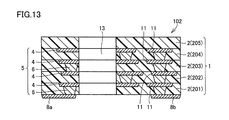
- a coil inner hole 13 is formed as shown in FIG.
- at least one of the plurality of insulating layers 2 is formed with a hole in a portion corresponding to the inner side of the coiled conductor structure 5, thereby removing a part of the conductor pattern 4 and insulating layer.
- the hole-side end face of 2 and the hole-side end face of the conductor pattern 4 are in the same plane. In this way, the laminated coil element 102 shown in FIG. 13 is obtained.
- the insulating layer 2 included in the laminate 1 may be slightly displaced in the horizontal direction due to an error when stacked.
- this deviation is also referred to as “loading deviation”. Since the position of the conductor pattern 4 is also shifted due to the stacking error, even when the coil inner hole 13 is formed by laser processing on the region 30, the end corresponding to the inside of the coiled conductor structure is removed in some conductor patterns. However, some conductor patterns may not be removed at all.
- FIG. 14 An example of a range removed by laser processing is shown in FIG. 14, for example.
- the shape is slightly different from that of the conductor pattern 4 shown in FIGS. 7 to 10, but the concept is common in the sense that it is a conductor pattern forming a part of the coil.
- a region 30 is set on the inner side of the conductor pattern 4 formed so that a part of the ring is interrupted so as to slightly overlap the inner peripheral edge. Laser processing is performed for this region 30.
- Such a concept regarding the region 30 to be removed in the drilling step S3 is similarly applied when removing by a method other than laser processing.
- At least one of the plurality of insulating layers 2 having the conductor pattern 4 that forms a part of the coil a hole is formed in a portion corresponding to the inside of the coiled conductor structure 5 to thereby form a conductor. Since the hole forming S3 is performed while removing a part of the pattern 4 so that the end surface on the hole side of the insulating layer 2 and the end surface on the hole side of the conductor pattern 4 are in the same plane, the at least 1 In one insulating layer 2, the end face 4 e on the coil inner hole 13 side of the conductor pattern 4 is parallel to the thickness direction 91, that is, a plane perpendicular to the main surface of the multilayer body 1.
- the punching step S3 is performed after the step S2 of obtaining the laminated body according to the flowchart shown in FIG. 4 is described.
- Step S2 for obtaining a laminate may be performed after the first step.
- the individual insulating layers 2 are stacked with the through holes 15 already formed therein. Even in this way, the laminated body 1 can be obtained by integrating the stacked insulating layers 2.
- the end corresponding to the inside of the coiled conductor structure 5 may not be removed at all in some of the conductor patterns 4, Considering the problem, the following situation is actually preferable. That is, in the drilling step S3, a hole is formed in a portion corresponding to the inside of the coiled conductor structure 5 over all of the plurality of insulating layers 2 to cover all of the plurality of insulating layers 2. It is preferable that a part of the conductor pattern 4 is removed. In order to do this, as shown in FIG. 17, when the conductor pattern 4 forming a part of the coil is formed, the conductor pattern 4 is formed so as to extend to the inside of the coil to some extent. It is possible to keep it.
- the diameter of the opening part inside the conductor pattern 4 which forms a part of the coil is small.
- the drilling step S3 may be performed as shown in FIG.
- the conductor forming part of the coil is formed by intentionally setting the diameter of the opening inside the conductor pattern 4 forming part of the coil smaller than the diameter of the region 30 irradiated with the laser beam 14.
- the inner end of the conductor pattern 4 can be disposed in the region 30 to which the laser beam 14 is irradiated.
- the coil inner hole 13 is formed as shown in FIG.
- the laminated coil element 103 is obtained.
- the end face 4e on the coil inner hole 13 side of the conductor pattern 4 is parallel to the thickness direction 91, that is, a laminated body. It becomes a plane perpendicular to the main surface of 1. That is, a thin portion does not occur at the end on the coil inner hole 13 side.
- the internal diameter of a coil can be arrange
- FIG. 21 shows an enlarged view of the Z2 portion in FIG.
- the basic configuration of the laminated coil element 104 in the present embodiment is the same as that of the laminated coil element 101 described in the first embodiment. However, it differs from the laminated coil element 101 in the following points.
- a plating film 16 is formed so as to cover the end face 4e on the coil inner hole 13 side of the conductor pattern 4 forming a part of the coil.
- the plating film 16 may only cover a part of the end face of the conductor pattern 4 on the coil inner hole 13 side, but is preferably formed to cover all.
- the plating film 16 may cover only a part of the end face of the conductor pattern 4 on the coil inner hole 13 side, but is formed so as to cover all. Preferably it is.
- the plating film 16 is formed so as to cover the end face 4e on the coil inner hole 13 side of the conductor pattern 4 forming a part of the coil, when a current flows through the coiled conductor structure 5 Current flows through the plating film 16 located on the innermost periphery.
- the ease of current flow in the coil can be improved by appropriately selecting the material of the plating film 16 and the vertical dimension.
- the material of the plating film 16 may be the same as the material of the conductor pattern 4. However, the plating film 16 is preferably formed of a material having better conductivity than the conductor pattern 4. In this way, the loss of electrical energy in the coil can be further reduced.
- the dimension of the plating film 16 in the thickness direction of the laminate 1 is preferably larger than the thickness of the conductor pattern 4. In the example shown in FIGS. 20 and 21, this condition is satisfied. In this way, even if the conductor pattern 4 is thin, the plating film 16 can secure a wide current path at the inner peripheral edge of the coil, and the loss of electric energy in the coil can be further reduced.
- FIG. 22 is a cross-sectional view taken at a cut end passing through a portion where the plating film 16w is formed on the inner periphery of the coil.
- the manufacturing method described in the second embodiment may be basically used as follows.
- a step of plating the hole-side end surface of the conductor pattern 4 may be included after the drilling step S3.
- Embodiment 4 With reference to FIG. 23, the laminated coil element 105 in Embodiment 4 based on this invention is demonstrated.
- the basic configuration of the laminated coil element 105 in the present embodiment is the same as that of the laminated coil element 101 described in the first embodiment. However, it differs from the laminated coil element 101 in the following points.
- An insulating material 17 is filled in the coil inner hole 13.
- the strength of the laminate 1 can be increased. Further, it is possible to prevent water and the like from entering from the inner surface of the coil inner hole 13.
- the insulating material 17 may be so-called underfill.
- the insulating material 17 may be an epoxy resin, for example.
- the insulating material 17 is preferably a material having a low dielectric constant.
- a low dielectric constant material having a relative dielectric constant of 5 or less is preferable.
- a liquid crystal polymer can be used as the low dielectric constant material.
- the insulating material 17 is preferably a magnetic material.
- the magnetic body here may be, for example, a mixture of ferrite and resin.
- the manufacturing method described in the second embodiment may be basically used as follows.
- the manufacturing method described in the second embodiment may include a step of filling the inner space of the hole with the insulating material 17 after the drilling step S3.
- the insulating material 17 is preferably a material having a low dielectric constant as described above, and particularly preferably a low dielectric constant material having a relative dielectric constant of 5 or less. In this way, it is possible to obtain a structure in which a low dielectric constant material is arranged inside the coil, and to increase the self-resonance frequency of the coil.
- the insulating material 17 may be a magnetic material. If it does in this way, the structure by which the magnetic body is arrange
- a solid insulating material 17 is inserted into a coil inner hole 13 formed by laminating a second insulating layer 202 to a fourth insulating layer 204.
- the insulating material 17 can be easily inserted due to the certain gap.
- the second insulating layer 202 to the fourth insulating layer 204 may be already integrated at this point in time, or may be simply stacked in a separated state. However, pre-integration is preferable because the insulating layer can be less likely to be displaced.
- the first insulating layer 201 is disposed below the second insulating layer 202, and the fifth insulating layer 205 is disposed above the fourth insulating layer 204.
- pressurization and heating are performed in the vertical direction.
- the structure shown in FIG. 25 is obtained. That is, the laminated coil element 106 is obtained.
- the first insulating layer 201 and the fifth insulating layer 205 disposed above and below the insulating material 17 between the coil inner hole 13 and the insulating material 17.
- the resin constituting the first insulating layer 201 and the fifth insulating layer 205 can easily flow into the gaps existing in. Therefore, even if there is a gap, the gap can be filled after pressurization and heating.
- this configuration makes it easier to flatten both main surfaces (upper surface and lower surface) of the laminated coil element during pressurization and heating, compared to the case where the first insulating layer 201 and the fifth insulating layer 205 are not provided. That is, even if a material that does not flow easily during pressurization and heating, such as an epoxy resin, is used as the insulating material 17, the first insulating layer 201 and the first insulating layer 201 made of a resin that easily flows during pressurization and heating are used.
- the presence of the 5 insulating layer 205 on the outermost surface absorbs the unevenness of the pressing surface and makes it easy to maintain the flatness of the laminated coil element.
- first insulating layer 201 and the fifth insulating layer 205 may be disposed.
- the first insulating layer 201 to the fourth insulating layer 204 may be integrated in advance to form a bottomed recess, and the insulating material 17 may be disposed in the recess.
- the fifth insulating layer 205 is covered so as to collectively cover the upper surfaces of the fourth insulating layer 204 and the insulating material 17, and pressurization and heating are performed in the vertical direction. By doing so, the laminated coil element 106 can be similarly obtained.
- the vertical dimension of the insulating material 17 is slightly larger than the total thickness from the second insulating layer 202 to the fourth insulating layer 204 before pressure and heating. Is preferred. By making it so large, the upper surface of the insulating material 17 protrudes from the upper surface of the fourth insulating layer 204 as shown in the Z3 portion of FIG. Thus, by making the dimension of the insulating material 17 in the vertical direction slightly larger, reliable pressing can be performed.
- the vertical dimension of the insulating material 17 may be the same as or slightly smaller than the total thickness from the second insulating layer 202 to the fourth insulating layer 204 before pressure and heating.
- the insulating layers in which holes are not formed are arranged one on top and the other on the upper and lower sides.
- one or both of the upper and lower sides are not limited to one layer and two or more layers are arranged. Also good.
- a conductor pattern 34 is formed in place of the conductor pattern 4 as shown in FIG.
- the conductor pattern 34 is not substantially annular but has a so-called solid shape in which the inside is substantially filled.
- the substantially annular conductor pattern 4 can be obtained as shown in FIG. 27 by removing the region 30 in the drilling step S3.
- This concept can also be adopted when the hole making step S3 is performed after the step S2 for obtaining the laminated body, and also when the step S2 for obtaining the laminated body is carried out after the hole making step S3.
- the portion in the region 30 of the conductor pattern 34 is also collectively removed when the coil inner hole 13 is opened.
- the through hole 15 is formed by removing a portion in the region 30 of the conductor pattern 34 in the individual insulating layer 2.
- the step S3 for forming a hole is shown as being performed by laser processing, but this is only an example.
- the step S3 for forming a hole may be performed by a known processing method other than laser processing.
- it may be a punching process.
- care should be taken so that the inner periphery of the conductor pattern is not deformed as much as possible.
- the end of the conductor pattern 4 on the coil inner hole 13 side preferably has a larger thickness in the thickness direction of the laminate 1 than the end of the conductor pattern 4 opposite to the coil inner hole 13 side.
- the end of the conductor pattern 4 on the side of the coil inner hole 13 is not locally thinned, but has an end face 4e that is vertically upright.
- a configuration in which the end portion on the side gradually becomes thinner toward the tip end also corresponds. For example, as shown in FIG.
- the end portion on the coil inner hole 13 side of the conductor pattern 4 is an end face 4e that is vertically cut in the middle after the thickness gradually decreases toward the end, A configuration in which the end portion on the side gradually becomes thinner toward the tip end also corresponds.
- FIG. 28 and FIG. 29 are merely typical examples, and the present invention is not limited to these. Compared with the end portion on the coil inner hole 13 side of the conductor pattern 4 and the end portion on the opposite side, It is preferable if the thickness can be evaluated as being thick.
- the present invention can be used for a laminated coil element and a manufacturing method thereof.
Landscapes
- Engineering & Computer Science (AREA)
- Power Engineering (AREA)
- Manufacturing & Machinery (AREA)
- Microelectronics & Electronic Packaging (AREA)
- Coils Or Transformers For Communication (AREA)
- Manufacturing Cores, Coils, And Magnets (AREA)
Abstract
Le but de la présente invention est de réduire, dans un élément de bobine stratifié, la perte d'énergie électrique provoquée durant l'écoulement de courant par un courant concentré au niveau d'une partie mince de la périphérie interne d'une bobine. Un élément de bobine stratifié (101) est pourvu d'un corps stratifié (1) comprenant une structure conductrice de type bobine (5) qui est formée par un axe d'enroulement dans le sens de l'épaisseur (91) par stratification d'une pluralité de couches isolantes (2) présentant des motifs conducteurs (4) formés sur les surfaces principales en tant que parties de la bobine et connectant électriquement chaque motif conducteur (4) dans le sens de l'épaisseur. Au niveau de la périphérie interne de la structure conductrice de type bobine (5), le corps stratifié (1) présente un trou interne de bobine (13) qui passe à travers la structure conductrice de type bobine (5) dans la direction de l'axe d'enroulement ou a une certaine profondeur dans la direction de l'axe d'enroulement. Dans au moins une couche de la pluralité de couches isolantes (2), la surface d'extrémité du motif conducteur (4) sur le trou de bobine intérieur (13) est de niveau avec la surface d'extrémité de la couche isolante (2) sur le côté du trou de bobine intérieur (13).
Priority Applications (3)
| Application Number | Priority Date | Filing Date | Title |
|---|---|---|---|
| JP2016507483A JP6206577B2 (ja) | 2014-03-14 | 2015-03-05 | 積層コイル素子およびその製造方法 |
| CN201590000204.3U CN206022030U (zh) | 2014-03-14 | 2015-03-05 | 层叠线圈元件 |
| US15/177,381 US10056181B2 (en) | 2014-03-14 | 2016-06-09 | Stacked coil element and method for manufacturing the same |
Applications Claiming Priority (2)
| Application Number | Priority Date | Filing Date | Title |
|---|---|---|---|
| JP2014052044 | 2014-03-14 | ||
| JP2014-052044 | 2014-03-14 |
Related Child Applications (1)
| Application Number | Title | Priority Date | Filing Date |
|---|---|---|---|
| US15/177,381 Continuation US10056181B2 (en) | 2014-03-14 | 2016-06-09 | Stacked coil element and method for manufacturing the same |
Publications (1)
| Publication Number | Publication Date |
|---|---|
| WO2015137226A1 true WO2015137226A1 (fr) | 2015-09-17 |
Family
ID=54071672
Family Applications (1)
| Application Number | Title | Priority Date | Filing Date |
|---|---|---|---|
| PCT/JP2015/056483 WO2015137226A1 (fr) | 2014-03-14 | 2015-03-05 | Élément de bobine stratifié et son procédé de fabrication |
Country Status (4)
| Country | Link |
|---|---|
| US (1) | US10056181B2 (fr) |
| JP (1) | JP6206577B2 (fr) |
| CN (1) | CN206022030U (fr) |
| WO (1) | WO2015137226A1 (fr) |
Cited By (3)
| Publication number | Priority date | Publication date | Assignee | Title |
|---|---|---|---|---|
| JPWO2017199747A1 (ja) * | 2016-05-19 | 2019-03-22 | 株式会社村田製作所 | 多層基板及び多層基板の製造方法 |
| JP2019062071A (ja) * | 2017-09-26 | 2019-04-18 | 株式会社村田製作所 | コイル部品およびその製造方法 |
| JP2020107782A (ja) * | 2018-12-28 | 2020-07-09 | 太陽誘電株式会社 | 積層コイル部品 |
Families Citing this family (9)
| Publication number | Priority date | Publication date | Assignee | Title |
|---|---|---|---|---|
| JP6787016B2 (ja) * | 2016-10-05 | 2020-11-18 | Tdk株式会社 | 積層コイル部品の製造方法 |
| KR101994758B1 (ko) * | 2017-10-16 | 2019-07-01 | 삼성전기주식회사 | 박막형 인덕터 |
| KR102069632B1 (ko) * | 2018-02-22 | 2020-01-23 | 삼성전기주식회사 | 인덕터 |
| JP7464352B2 (ja) * | 2018-03-09 | 2024-04-09 | 日東電工株式会社 | 配線基板およびその製造方法 |
| KR102064064B1 (ko) | 2018-04-09 | 2020-01-08 | 삼성전기주식회사 | 인덕터 |
| JP2020035855A (ja) * | 2018-08-29 | 2020-03-05 | 株式会社村田製作所 | 積層コイル部品、及び、積層コイル部品の製造方法 |
| JP7253343B2 (ja) * | 2018-09-14 | 2023-04-06 | Koa株式会社 | 電流検出装置 |
| CN109994305A (zh) * | 2019-03-27 | 2019-07-09 | 武汉合康亿盛电气连接系统有限公司 | 一种层叠式电感器 |
| TWI766342B (zh) * | 2020-08-10 | 2022-06-01 | 大陸商鵬鼎控股(深圳)股份有限公司 | 電路板及其製備方法 |
Citations (4)
| Publication number | Priority date | Publication date | Assignee | Title |
|---|---|---|---|---|
| JPH07263231A (ja) * | 1994-03-25 | 1995-10-13 | Tdk Corp | 積層部品 |
| JP2006041320A (ja) * | 2004-07-29 | 2006-02-09 | Kyocera Corp | 積層型インダクタ |
| JP2009152406A (ja) * | 2007-12-20 | 2009-07-09 | Panasonic Corp | インダクタとその製造方法 |
| JP2011165807A (ja) * | 2010-02-08 | 2011-08-25 | Murata Mfg Co Ltd | 電子部品及びその製造方法 |
Family Cites Families (8)
| Publication number | Priority date | Publication date | Assignee | Title |
|---|---|---|---|---|
| US3848210A (en) * | 1972-12-11 | 1974-11-12 | Vanguard Electronics | Miniature inductor |
| US4985374A (en) * | 1989-06-30 | 1991-01-15 | Kabushiki Kaisha Toshiba | Making a semiconductor device with ammonia treatment of photoresist |
| JPH1197245A (ja) * | 1997-09-19 | 1999-04-09 | Tokin Corp | 積層型インダクタンス素子 |
| JP2007281025A (ja) | 2006-04-03 | 2007-10-25 | Sumida Corporation | 積層チップコイル |
| WO2009069387A1 (fr) * | 2007-11-29 | 2009-06-04 | Murata Manufacturing Co., Ltd. | Composant électronique stratifié |
| JP2010225918A (ja) * | 2009-03-24 | 2010-10-07 | Toshiba Corp | 不揮発性半導体記憶装置及びその製造方法 |
| KR101072784B1 (ko) * | 2009-05-01 | 2011-10-14 | (주)창성 | 자성시트를 이용한 적층형 인덕터 및 그 제조방법 |
| CN102272927B (zh) * | 2009-08-03 | 2014-09-10 | 松下电器产业株式会社 | 半导体存储器的制造方法 |
-
2015
- 2015-03-05 CN CN201590000204.3U patent/CN206022030U/zh active Active
- 2015-03-05 WO PCT/JP2015/056483 patent/WO2015137226A1/fr active Application Filing
- 2015-03-05 JP JP2016507483A patent/JP6206577B2/ja active Active
-
2016
- 2016-06-09 US US15/177,381 patent/US10056181B2/en active Active
Patent Citations (4)
| Publication number | Priority date | Publication date | Assignee | Title |
|---|---|---|---|---|
| JPH07263231A (ja) * | 1994-03-25 | 1995-10-13 | Tdk Corp | 積層部品 |
| JP2006041320A (ja) * | 2004-07-29 | 2006-02-09 | Kyocera Corp | 積層型インダクタ |
| JP2009152406A (ja) * | 2007-12-20 | 2009-07-09 | Panasonic Corp | インダクタとその製造方法 |
| JP2011165807A (ja) * | 2010-02-08 | 2011-08-25 | Murata Mfg Co Ltd | 電子部品及びその製造方法 |
Cited By (4)
| Publication number | Priority date | Publication date | Assignee | Title |
|---|---|---|---|---|
| JPWO2017199747A1 (ja) * | 2016-05-19 | 2019-03-22 | 株式会社村田製作所 | 多層基板及び多層基板の製造方法 |
| JP2019062071A (ja) * | 2017-09-26 | 2019-04-18 | 株式会社村田製作所 | コイル部品およびその製造方法 |
| JP2020107782A (ja) * | 2018-12-28 | 2020-07-09 | 太陽誘電株式会社 | 積層コイル部品 |
| JP7272790B2 (ja) | 2018-12-28 | 2023-05-12 | 太陽誘電株式会社 | 積層コイル部品 |
Also Published As
| Publication number | Publication date |
|---|---|
| JPWO2015137226A1 (ja) | 2017-04-06 |
| US20160293322A1 (en) | 2016-10-06 |
| JP6206577B2 (ja) | 2017-10-04 |
| CN206022030U (zh) | 2017-03-15 |
| US10056181B2 (en) | 2018-08-21 |
Similar Documents
| Publication | Publication Date | Title |
|---|---|---|
| JP6206577B2 (ja) | 積層コイル素子およびその製造方法 | |
| TWI613685B (zh) | 電磁元件及其線圈結構 | |
| KR101862409B1 (ko) | 칩 인덕터 및 칩 인덕터 제조방법 | |
| KR101983192B1 (ko) | 코일 전자부품 | |
| JP5757376B1 (ja) | 多層基板の製造方法、多層基板および電磁石 | |
| US9743511B1 (en) | Rigid flex circuit board | |
| KR100644790B1 (ko) | 적층 코일 부품 및 그 제조방법 | |
| JP2018207028A (ja) | コイル部品及びその製造方法 | |
| JP6048509B2 (ja) | 積層型インダクタ素子 | |
| WO2014103530A1 (fr) | Substrat avec composant intégré | |
| JP5765685B2 (ja) | 磁気素子の製造方法 | |
| JP5831633B2 (ja) | 積層型素子およびその製造方法 | |
| JP2010034171A (ja) | 積層型コイル | |
| JP5652481B2 (ja) | 樹脂多層基板およびその製造方法 | |
| JP2014225604A (ja) | 樹脂多層基板およびその製造方法 | |
| JP2018032841A (ja) | 積層電子部品及びその製造方法 | |
| JP5935506B2 (ja) | 積層基板およびその製造方法 | |
| JP5787021B2 (ja) | 樹脂多層基板 | |
| JP2019102783A (ja) | コイル部品 | |
| JP6232976B2 (ja) | 多層基板の製造方法、多層基板および電磁石 | |
| JP2015149337A (ja) | 多層基板およびその製造方法 | |
| CN208273381U (zh) | 电路基板 | |
| KR20190108456A (ko) | 코일 부품 | |
| KR102163041B1 (ko) | 회로기판, 회로기판 제조방법 및 2단 비아 구조 | |
| JP2016213437A (ja) | コイル内蔵素子、コイルアンテナ、電子機器およびコイル内蔵素子の製造方法 |
Legal Events
| Date | Code | Title | Description |
|---|---|---|---|
| 121 | Ep: the epo has been informed by wipo that ep was designated in this application |
Ref document number: 15760911 Country of ref document: EP Kind code of ref document: A1 |
|
| ENP | Entry into the national phase |
Ref document number: 2016507483 Country of ref document: JP Kind code of ref document: A |
|
| NENP | Non-entry into the national phase |
Ref country code: DE |
|
| 122 | Ep: pct application non-entry in european phase |
Ref document number: 15760911 Country of ref document: EP Kind code of ref document: A1 |