WO2015137226A1 - 積層コイル素子およびその製造方法 - Google Patents
積層コイル素子およびその製造方法 Download PDFInfo
- Publication number
- WO2015137226A1 WO2015137226A1 PCT/JP2015/056483 JP2015056483W WO2015137226A1 WO 2015137226 A1 WO2015137226 A1 WO 2015137226A1 JP 2015056483 W JP2015056483 W JP 2015056483W WO 2015137226 A1 WO2015137226 A1 WO 2015137226A1
- Authority
- WO
- WIPO (PCT)
- Prior art keywords
- coil
- conductor pattern
- laminated
- coil element
- insulating layer
- Prior art date
Links
- 238000004519 manufacturing process Methods 0.000 title claims description 45
- 238000000034 method Methods 0.000 title claims description 25
- 238000004804 winding Methods 0.000 claims abstract description 14
- 238000010030 laminating Methods 0.000 claims abstract description 8
- 239000004020 conductor Substances 0.000 claims description 148
- 239000011810 insulating material Substances 0.000 claims description 28
- 238000007747 plating Methods 0.000 claims description 20
- 230000002093 peripheral effect Effects 0.000 claims description 15
- 238000005553 drilling Methods 0.000 claims description 13
- 238000004080 punching Methods 0.000 claims description 6
- 230000000149 penetrating effect Effects 0.000 claims description 2
- 239000000126 substance Substances 0.000 claims 1
- 239000010410 layer Substances 0.000 description 133
- 238000012986 modification Methods 0.000 description 13
- 230000004048 modification Effects 0.000 description 13
- 239000000463 material Substances 0.000 description 11
- 238000010438 heat treatment Methods 0.000 description 10
- 239000011888 foil Substances 0.000 description 9
- 229920005989 resin Polymers 0.000 description 6
- 239000011347 resin Substances 0.000 description 6
- 239000012212 insulator Substances 0.000 description 5
- 238000005530 etching Methods 0.000 description 4
- 229920000106 Liquid crystal polymer Polymers 0.000 description 3
- 239000004977 Liquid-crystal polymers (LCPs) Substances 0.000 description 3
- 239000000696 magnetic material Substances 0.000 description 3
- 238000007650 screen-printing Methods 0.000 description 3
- 229920005992 thermoplastic resin Polymers 0.000 description 3
- 239000003822 epoxy resin Substances 0.000 description 2
- 239000011229 interlayer Substances 0.000 description 2
- 239000002184 metal Substances 0.000 description 2
- 229910052751 metal Inorganic materials 0.000 description 2
- 238000000059 patterning Methods 0.000 description 2
- 229920000647 polyepoxide Polymers 0.000 description 2
- 238000003825 pressing Methods 0.000 description 2
- 239000007787 solid Substances 0.000 description 2
- RYGMFSIKBFXOCR-UHFFFAOYSA-N Copper Chemical compound [Cu] RYGMFSIKBFXOCR-UHFFFAOYSA-N 0.000 description 1
- 239000011889 copper foil Substances 0.000 description 1
- 238000005520 cutting process Methods 0.000 description 1
- 230000007423 decrease Effects 0.000 description 1
- 230000010354 integration Effects 0.000 description 1
- 238000003475 lamination Methods 0.000 description 1
- CNQCVBJFEGMYDW-UHFFFAOYSA-N lawrencium atom Chemical compound [Lr] CNQCVBJFEGMYDW-UHFFFAOYSA-N 0.000 description 1
- 239000000203 mixture Substances 0.000 description 1
- ORQBXQOJMQIAOY-UHFFFAOYSA-N nobelium Chemical compound [No] ORQBXQOJMQIAOY-UHFFFAOYSA-N 0.000 description 1
- 238000003672 processing method Methods 0.000 description 1
- XLYOFNOQVPJJNP-UHFFFAOYSA-N water Substances O XLYOFNOQVPJJNP-UHFFFAOYSA-N 0.000 description 1
- 229910000859 α-Fe Inorganic materials 0.000 description 1
Images


Classifications
-
- H—ELECTRICITY
- H01—ELECTRIC ELEMENTS
- H01F—MAGNETS; INDUCTANCES; TRANSFORMERS; SELECTION OF MATERIALS FOR THEIR MAGNETIC PROPERTIES
- H01F27/00—Details of transformers or inductances, in general
- H01F27/28—Coils; Windings; Conductive connections
- H01F27/2804—Printed windings
-
- H—ELECTRICITY
- H01—ELECTRIC ELEMENTS
- H01F—MAGNETS; INDUCTANCES; TRANSFORMERS; SELECTION OF MATERIALS FOR THEIR MAGNETIC PROPERTIES
- H01F17/00—Fixed inductances of the signal type
- H01F17/0006—Printed inductances
- H01F17/0013—Printed inductances with stacked layers
-
- H—ELECTRICITY
- H01—ELECTRIC ELEMENTS
- H01F—MAGNETS; INDUCTANCES; TRANSFORMERS; SELECTION OF MATERIALS FOR THEIR MAGNETIC PROPERTIES
- H01F17/00—Fixed inductances of the signal type
- H01F17/0006—Printed inductances
- H01F17/0033—Printed inductances with the coil helically wound around a magnetic core
-
- H—ELECTRICITY
- H01—ELECTRIC ELEMENTS
- H01F—MAGNETS; INDUCTANCES; TRANSFORMERS; SELECTION OF MATERIALS FOR THEIR MAGNETIC PROPERTIES
- H01F27/00—Details of transformers or inductances, in general
- H01F27/24—Magnetic cores
-
- H—ELECTRICITY
- H01—ELECTRIC ELEMENTS
- H01F—MAGNETS; INDUCTANCES; TRANSFORMERS; SELECTION OF MATERIALS FOR THEIR MAGNETIC PROPERTIES
- H01F41/00—Apparatus or processes specially adapted for manufacturing or assembling magnets, inductances or transformers; Apparatus or processes specially adapted for manufacturing materials characterised by their magnetic properties
- H01F41/02—Apparatus or processes specially adapted for manufacturing or assembling magnets, inductances or transformers; Apparatus or processes specially adapted for manufacturing materials characterised by their magnetic properties for manufacturing cores, coils, or magnets
- H01F41/0206—Manufacturing of magnetic cores by mechanical means
-
- H—ELECTRICITY
- H01—ELECTRIC ELEMENTS
- H01F—MAGNETS; INDUCTANCES; TRANSFORMERS; SELECTION OF MATERIALS FOR THEIR MAGNETIC PROPERTIES
- H01F41/00—Apparatus or processes specially adapted for manufacturing or assembling magnets, inductances or transformers; Apparatus or processes specially adapted for manufacturing materials characterised by their magnetic properties
- H01F41/02—Apparatus or processes specially adapted for manufacturing or assembling magnets, inductances or transformers; Apparatus or processes specially adapted for manufacturing materials characterised by their magnetic properties for manufacturing cores, coils, or magnets
- H01F41/04—Apparatus or processes specially adapted for manufacturing or assembling magnets, inductances or transformers; Apparatus or processes specially adapted for manufacturing materials characterised by their magnetic properties for manufacturing cores, coils, or magnets for manufacturing coils
- H01F41/041—Printed circuit coils
- H01F41/042—Printed circuit coils by thin film techniques
-
- H—ELECTRICITY
- H01—ELECTRIC ELEMENTS
- H01F—MAGNETS; INDUCTANCES; TRANSFORMERS; SELECTION OF MATERIALS FOR THEIR MAGNETIC PROPERTIES
- H01F41/00—Apparatus or processes specially adapted for manufacturing or assembling magnets, inductances or transformers; Apparatus or processes specially adapted for manufacturing materials characterised by their magnetic properties
- H01F41/02—Apparatus or processes specially adapted for manufacturing or assembling magnets, inductances or transformers; Apparatus or processes specially adapted for manufacturing materials characterised by their magnetic properties for manufacturing cores, coils, or magnets
- H01F41/04—Apparatus or processes specially adapted for manufacturing or assembling magnets, inductances or transformers; Apparatus or processes specially adapted for manufacturing materials characterised by their magnetic properties for manufacturing cores, coils, or magnets for manufacturing coils
- H01F41/041—Printed circuit coils
- H01F41/046—Printed circuit coils structurally combined with ferromagnetic material
-
- H—ELECTRICITY
- H01—ELECTRIC ELEMENTS
- H01F—MAGNETS; INDUCTANCES; TRANSFORMERS; SELECTION OF MATERIALS FOR THEIR MAGNETIC PROPERTIES
- H01F5/00—Coils
-
- H—ELECTRICITY
- H01—ELECTRIC ELEMENTS
- H01F—MAGNETS; INDUCTANCES; TRANSFORMERS; SELECTION OF MATERIALS FOR THEIR MAGNETIC PROPERTIES
- H01F27/00—Details of transformers or inductances, in general
- H01F27/28—Coils; Windings; Conductive connections
- H01F27/2804—Printed windings
- H01F2027/2809—Printed windings on stacked layers
Definitions
- the present invention relates to a laminated coil element and a manufacturing method thereof.
- a laminated coil element can be obtained, for example, by stacking and integrating insulating sheets having a conductor pattern in the shape of a part of the coil on the main surface.
- An insulator sheet having a conductor pattern of a shape forming a part of a coil on the main surface can be obtained by etching the conductor foil on an insulator sheet having a conductor foil stretched over the entire main surface, for example. it can. Alternatively, it can be obtained by screen-printing a conductive paste on the main surface of the insulator sheet on which the conductor foil is not stretched, instead of using the insulator sheet on which the conductor foil is stretched in advance.
- a through hole penetrating the first magnetic body portion is formed, and the second magnetic material is formed in the through hole.
- Patent Document 1 Japanese Patent Application Laid-Open No. 2007-28125
- the conductor pattern forming a part of the coil is obtained by etching or screen printing.
- the end of the obtained conductor pattern is perpendicular to the main surface. It becomes a slope instead of a smooth surface, and the base of the slope becomes a thin part as a conductor pattern. If there is such a thin part at the end of the conductor pattern on the inner peripheral side of the coil, when the current is actually passed through the laminated coil element, the current is concentrated at the thin part at the inner peripheral side, and the electric current is concentrated. Energy loss will occur.
- the present invention provides a laminated coil element capable of reducing a loss of electric energy caused by current concentration in a thin portion of an end portion on the inner peripheral side of a coil when a current is passed, and a method for manufacturing the same.
- a laminated coil element capable of reducing a loss of electric energy caused by current concentration in a thin portion of an end portion on the inner peripheral side of a coil when a current is passed, and a method for manufacturing the same.
- the laminated coil element according to the present invention is formed by laminating a plurality of insulating layers in which a conductor pattern forming a part of a coil is formed on a main surface, and electrically connecting the conductor patterns in the thickness direction.
- the end surface of the conductor pattern on the coil inner hole side is the insulating It is in the same plane as the end face of the layer on the coil inner hole side.
- a thin portion does not occur at the end of the conductor pattern 4 on the coil inner hole 13 side. Therefore, it is possible to reduce a loss of electric energy due to the current being concentrated on a thin portion of the end portion on the inner peripheral side of the coil when a current is passed.
- Embodiment 1 It is a perspective view of the laminated coil element in Embodiment 1 based on this invention. It is arrow sectional drawing regarding the II-II line
- FIG. 1 shows a cross-sectional view taken along the line II-II in FIG.
- FIG. 3 shows an enlarged view of the Z1 portion in FIG.
- a plurality of insulating layers 2 each having a conductor pattern 4 forming a part of a coil are formed on the main surface, and the conductor patterns 4 are electrically connected in the thickness direction.
- the laminated body 1 including the coiled conductor structure 5 formed with the thickness direction 91 as the winding axis is provided.
- the multilayer body 1 has a coil inner hole 13 that penetrates in the direction of the winding axis or has a depth direction in the direction of the winding axis on the inner peripheral side of the coiled conductor structure 5.
- the end surface 4 e on the coil inner hole 13 side of the conductor pattern 4 is in the same plane as the end surface 2 e on the coil inner hole 13 side of the insulating layer 2. is there.
- the electrical connection in the thickness direction between the conductor patterns 4 is made by conductor vias 6 as interlayer connection conductors.
- the coil inner hole 13 is a hole that completely penetrates the laminated body 1 in the thickness direction, but instead of the through hole like the coil inner hole 13, the bottom is not penetrated. It may be a hole.
- the end surface 4 e on the coil inner hole 13 side of the conductor pattern 4 is in the same plane as the end surface 2 e on the coil inner hole 13 side of the insulating layer 2. Therefore, it can be said that the end face 4 e is parallel to the thickness direction 91. In other words, the end surface 4 e is a surface perpendicular to the main surface of the insulating layer 2. In such a configuration, a thin portion does not occur at the end of the conductor pattern 4 on the coil inner hole 13 side in the at least part of the insulating layer 2 included in the multilayer body 1. Therefore, it is possible to reduce a loss of electric energy due to the current being concentrated on a thin portion of the end portion on the inner peripheral side of the coil when a current is passed.
- the coil inner hole 13 may be formed by drilling through holes in the individual insulating layers 2 in a separated state before lamination. It is good also as forming the coil inner hole 13 collectively after laminating
- the example shown in FIG. 2 has a configuration that satisfies this condition. By adopting this configuration, the position of the inner peripheral side of the coiled conductor structure 5 is aligned within the range of the two or more insulating layers 2, and the accuracy of the coil is improved.
- the end face 4e on the coil inner hole 13 side of the conductor pattern 4 and the end face 2e on the coil inner hole 13 side of the insulating layer 2 are all in the same plane over all of the plurality of insulating layers 2. Is preferred.
- the example shown in FIG. 2 has a configuration that satisfies this condition. By adopting this configuration, all the positions on the inner peripheral side of the coiled conductor structure 5 are aligned, and the reproducibility of the coil characteristics is improved. Moreover, if it is this structure, after forming the laminated body 1, it will become easy to produce by opening the coil inner hole 13 collectively.
- the outer shape of the laminated coil element 101 is a rectangular parallelepiped whose length in the left-right direction in the figure is slightly longer than the length in the depth direction in the figure, but this is only an example.
- the shape of the laminated coil element may be other shapes.
- the coil inner hole 13 is provided in a substantially square shape at a position slightly deviated from the center of the laminated coil element 101. However, this is merely an example, and the shape and position of the coil inner hole are shown in FIG. It is not restricted to what was shown in 1.
- FIGS. 4 to 14 a method for manufacturing a laminated coil element according to the second embodiment of the present invention will be described.
- the method for manufacturing a laminated coil element in the present embodiment is a method for obtaining the laminated coil element described in the first embodiment.
- FIG. 4 shows a flowchart of the method for manufacturing the laminated coil element in the present embodiment.
- a plurality of insulating layers in which a conductor pattern forming a part of a coil is formed on the main surface are laminated, and the conductor patterns are electrically connected in the thickness direction.
- a drilling process is performed so that the end surface on the hole side of the insulating layer and the end surface on the hole side of the conductor pattern are in the same plane.
- step S1 for example, five insulating layers 2 are prepared as shown in FIG.
- the insulating layer 2 can be formed by cutting out a desired shape from an insulating sheet.
- a conductor pattern 4 forming a part of a coil and a conductor pattern 11 for other purposes are formed as necessary.
- the conductor patterns 4 and 11 can be formed, for example, by patterning the conductor foil by etching or the like in an insulating sheet in which the conductor foil is stretched over the entire area of one side.
- the conductor foil is, for example, a metal foil.
- the metal foil here is, for example, a copper foil.
- the conductor patterns 4 and 11 may be formed by screen printing a conductor paste on the surface of the insulating sheet in addition to patterning by etching.
- Conductive vias 6 are also formed in the insulating layer 2 so as to penetrate the thickness direction and electrically connect both the front and back surfaces.
- the conductive via 6 can be formed by filling the through hole with a conductive paste after a through hole is made in the insulating layer 2 by laser.
- the insulating layers 2 are displayed in the order in which they are stacked.
- a plurality of insulating layers 2 are referred to as a first insulating layer 201, a second insulating layer 202, a third insulating layer 203, a fourth insulating layer 204, and a fifth insulating layer 205 in order from the bottom.
- FIGS. 6 to 10 show the states of the lower surfaces of the first insulating layer 201 to the fifth insulating layer 205, respectively.
- Conductive patterns 4 are formed on the lower surfaces of the second insulating layer 202 to the fifth insulating layer 205. In the example shown in FIG. 5 to FIG.
- the second insulating layer 202 to the fifth insulating layer 205 correspond to the “plural insulating layers” in the step S1.
- the conductor pattern 4 is formed in portions corresponding to the half circumference of the coil, and these are alternately stacked and electrically connected to each other. It is planned that the conductor structure 5 is formed.
- pad electrodes 8a and 8b electrically connected to the coiled conductor structure 5 are formed.
- the conductor pattern 11 is also formed on the lower surfaces of the second insulating layer 202 to the fourth insulating layer 204.
- the conductor pattern 11 is for electrically connecting one end of the uppermost layer of the coiled conductor structure 5 to the lower surface of the multilayer body.
- “one end of the uppermost layer of the coiled conductor structure 5” is the end 4r of the conductor pattern 4 formed on the fifth insulating layer 205 as shown in FIG.
- the term “insulating layer 2” includes not only a piece that has already been cut off, but also the meaning of a part of the insulating sheet before being cut off from the insulating sheet.
- the insulator sheet is, for example, a resin sheet.
- the resin sheet is, for example, a thermoplastic resin sheet.
- a liquid crystal polymer (LCP) can be employed.
- the insulating layer 2 on which the conductor pattern 4 is formed is laminated to obtain a laminate. That is, the first insulating layer 201 to the fifth insulating layer 205 are stacked and integrated in the order shown in FIG.
- the insulating layer 2 is formed of a thermoplastic resin sheet, pressure may be applied while heating in order to integrate.
- the laminated body 1 is obtained.
- the laminate 1 includes the second insulating layer 202 to the fifth insulating layer 205 corresponding to the “plurality of resin layers” in step S1, and further includes the insulating layer 2 that does not include the conductor pattern that forms part of the coil.
- the first insulating layer 201 is also included.
- the insulating layer 2 that does not include the conductor pattern that forms part of the coil may be included in the group of insulating layers 2 to be the stacked body 1.
- laser processing is performed as a drilling step S3. That is, the laser beam 14 is irradiated so as to remove the region 30 shown in the drawing.
- a coil inner hole 13 is formed as shown in FIG.
- at least one of the plurality of insulating layers 2 is formed with a hole in a portion corresponding to the inner side of the coiled conductor structure 5, thereby removing a part of the conductor pattern 4 and insulating layer.
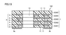
- the hole-side end face of 2 and the hole-side end face of the conductor pattern 4 are in the same plane. In this way, the laminated coil element 102 shown in FIG. 13 is obtained.
- the insulating layer 2 included in the laminate 1 may be slightly displaced in the horizontal direction due to an error when stacked.
- this deviation is also referred to as “loading deviation”. Since the position of the conductor pattern 4 is also shifted due to the stacking error, even when the coil inner hole 13 is formed by laser processing on the region 30, the end corresponding to the inside of the coiled conductor structure is removed in some conductor patterns. However, some conductor patterns may not be removed at all.
- FIG. 14 An example of a range removed by laser processing is shown in FIG. 14, for example.
- the shape is slightly different from that of the conductor pattern 4 shown in FIGS. 7 to 10, but the concept is common in the sense that it is a conductor pattern forming a part of the coil.
- a region 30 is set on the inner side of the conductor pattern 4 formed so that a part of the ring is interrupted so as to slightly overlap the inner peripheral edge. Laser processing is performed for this region 30.
- Such a concept regarding the region 30 to be removed in the drilling step S3 is similarly applied when removing by a method other than laser processing.
- At least one of the plurality of insulating layers 2 having the conductor pattern 4 that forms a part of the coil a hole is formed in a portion corresponding to the inside of the coiled conductor structure 5 to thereby form a conductor. Since the hole forming S3 is performed while removing a part of the pattern 4 so that the end surface on the hole side of the insulating layer 2 and the end surface on the hole side of the conductor pattern 4 are in the same plane, the at least 1 In one insulating layer 2, the end face 4 e on the coil inner hole 13 side of the conductor pattern 4 is parallel to the thickness direction 91, that is, a plane perpendicular to the main surface of the multilayer body 1.
- the punching step S3 is performed after the step S2 of obtaining the laminated body according to the flowchart shown in FIG. 4 is described.
- Step S2 for obtaining a laminate may be performed after the first step.
- the individual insulating layers 2 are stacked with the through holes 15 already formed therein. Even in this way, the laminated body 1 can be obtained by integrating the stacked insulating layers 2.
- the end corresponding to the inside of the coiled conductor structure 5 may not be removed at all in some of the conductor patterns 4, Considering the problem, the following situation is actually preferable. That is, in the drilling step S3, a hole is formed in a portion corresponding to the inside of the coiled conductor structure 5 over all of the plurality of insulating layers 2 to cover all of the plurality of insulating layers 2. It is preferable that a part of the conductor pattern 4 is removed. In order to do this, as shown in FIG. 17, when the conductor pattern 4 forming a part of the coil is formed, the conductor pattern 4 is formed so as to extend to the inside of the coil to some extent. It is possible to keep it.
- the diameter of the opening part inside the conductor pattern 4 which forms a part of the coil is small.
- the drilling step S3 may be performed as shown in FIG.
- the conductor forming part of the coil is formed by intentionally setting the diameter of the opening inside the conductor pattern 4 forming part of the coil smaller than the diameter of the region 30 irradiated with the laser beam 14.
- the inner end of the conductor pattern 4 can be disposed in the region 30 to which the laser beam 14 is irradiated.
- the coil inner hole 13 is formed as shown in FIG.
- the laminated coil element 103 is obtained.
- the end face 4e on the coil inner hole 13 side of the conductor pattern 4 is parallel to the thickness direction 91, that is, a laminated body. It becomes a plane perpendicular to the main surface of 1. That is, a thin portion does not occur at the end on the coil inner hole 13 side.
- the internal diameter of a coil can be arrange
- FIG. 21 shows an enlarged view of the Z2 portion in FIG.
- the basic configuration of the laminated coil element 104 in the present embodiment is the same as that of the laminated coil element 101 described in the first embodiment. However, it differs from the laminated coil element 101 in the following points.
- a plating film 16 is formed so as to cover the end face 4e on the coil inner hole 13 side of the conductor pattern 4 forming a part of the coil.
- the plating film 16 may only cover a part of the end face of the conductor pattern 4 on the coil inner hole 13 side, but is preferably formed to cover all.
- the plating film 16 may cover only a part of the end face of the conductor pattern 4 on the coil inner hole 13 side, but is formed so as to cover all. Preferably it is.
- the plating film 16 is formed so as to cover the end face 4e on the coil inner hole 13 side of the conductor pattern 4 forming a part of the coil, when a current flows through the coiled conductor structure 5 Current flows through the plating film 16 located on the innermost periphery.
- the ease of current flow in the coil can be improved by appropriately selecting the material of the plating film 16 and the vertical dimension.
- the material of the plating film 16 may be the same as the material of the conductor pattern 4. However, the plating film 16 is preferably formed of a material having better conductivity than the conductor pattern 4. In this way, the loss of electrical energy in the coil can be further reduced.
- the dimension of the plating film 16 in the thickness direction of the laminate 1 is preferably larger than the thickness of the conductor pattern 4. In the example shown in FIGS. 20 and 21, this condition is satisfied. In this way, even if the conductor pattern 4 is thin, the plating film 16 can secure a wide current path at the inner peripheral edge of the coil, and the loss of electric energy in the coil can be further reduced.
- FIG. 22 is a cross-sectional view taken at a cut end passing through a portion where the plating film 16w is formed on the inner periphery of the coil.
- the manufacturing method described in the second embodiment may be basically used as follows.
- a step of plating the hole-side end surface of the conductor pattern 4 may be included after the drilling step S3.
- Embodiment 4 With reference to FIG. 23, the laminated coil element 105 in Embodiment 4 based on this invention is demonstrated.
- the basic configuration of the laminated coil element 105 in the present embodiment is the same as that of the laminated coil element 101 described in the first embodiment. However, it differs from the laminated coil element 101 in the following points.
- An insulating material 17 is filled in the coil inner hole 13.
- the strength of the laminate 1 can be increased. Further, it is possible to prevent water and the like from entering from the inner surface of the coil inner hole 13.
- the insulating material 17 may be so-called underfill.
- the insulating material 17 may be an epoxy resin, for example.
- the insulating material 17 is preferably a material having a low dielectric constant.
- a low dielectric constant material having a relative dielectric constant of 5 or less is preferable.
- a liquid crystal polymer can be used as the low dielectric constant material.
- the insulating material 17 is preferably a magnetic material.
- the magnetic body here may be, for example, a mixture of ferrite and resin.
- the manufacturing method described in the second embodiment may be basically used as follows.
- the manufacturing method described in the second embodiment may include a step of filling the inner space of the hole with the insulating material 17 after the drilling step S3.
- the insulating material 17 is preferably a material having a low dielectric constant as described above, and particularly preferably a low dielectric constant material having a relative dielectric constant of 5 or less. In this way, it is possible to obtain a structure in which a low dielectric constant material is arranged inside the coil, and to increase the self-resonance frequency of the coil.
- the insulating material 17 may be a magnetic material. If it does in this way, the structure by which the magnetic body is arrange
- a solid insulating material 17 is inserted into a coil inner hole 13 formed by laminating a second insulating layer 202 to a fourth insulating layer 204.
- the insulating material 17 can be easily inserted due to the certain gap.
- the second insulating layer 202 to the fourth insulating layer 204 may be already integrated at this point in time, or may be simply stacked in a separated state. However, pre-integration is preferable because the insulating layer can be less likely to be displaced.
- the first insulating layer 201 is disposed below the second insulating layer 202, and the fifth insulating layer 205 is disposed above the fourth insulating layer 204.
- pressurization and heating are performed in the vertical direction.
- the structure shown in FIG. 25 is obtained. That is, the laminated coil element 106 is obtained.
- the first insulating layer 201 and the fifth insulating layer 205 disposed above and below the insulating material 17 between the coil inner hole 13 and the insulating material 17.
- the resin constituting the first insulating layer 201 and the fifth insulating layer 205 can easily flow into the gaps existing in. Therefore, even if there is a gap, the gap can be filled after pressurization and heating.
- this configuration makes it easier to flatten both main surfaces (upper surface and lower surface) of the laminated coil element during pressurization and heating, compared to the case where the first insulating layer 201 and the fifth insulating layer 205 are not provided. That is, even if a material that does not flow easily during pressurization and heating, such as an epoxy resin, is used as the insulating material 17, the first insulating layer 201 and the first insulating layer 201 made of a resin that easily flows during pressurization and heating are used.
- the presence of the 5 insulating layer 205 on the outermost surface absorbs the unevenness of the pressing surface and makes it easy to maintain the flatness of the laminated coil element.
- first insulating layer 201 and the fifth insulating layer 205 may be disposed.
- the first insulating layer 201 to the fourth insulating layer 204 may be integrated in advance to form a bottomed recess, and the insulating material 17 may be disposed in the recess.
- the fifth insulating layer 205 is covered so as to collectively cover the upper surfaces of the fourth insulating layer 204 and the insulating material 17, and pressurization and heating are performed in the vertical direction. By doing so, the laminated coil element 106 can be similarly obtained.
- the vertical dimension of the insulating material 17 is slightly larger than the total thickness from the second insulating layer 202 to the fourth insulating layer 204 before pressure and heating. Is preferred. By making it so large, the upper surface of the insulating material 17 protrudes from the upper surface of the fourth insulating layer 204 as shown in the Z3 portion of FIG. Thus, by making the dimension of the insulating material 17 in the vertical direction slightly larger, reliable pressing can be performed.
- the vertical dimension of the insulating material 17 may be the same as or slightly smaller than the total thickness from the second insulating layer 202 to the fourth insulating layer 204 before pressure and heating.
- the insulating layers in which holes are not formed are arranged one on top and the other on the upper and lower sides.
- one or both of the upper and lower sides are not limited to one layer and two or more layers are arranged. Also good.
- a conductor pattern 34 is formed in place of the conductor pattern 4 as shown in FIG.
- the conductor pattern 34 is not substantially annular but has a so-called solid shape in which the inside is substantially filled.
- the substantially annular conductor pattern 4 can be obtained as shown in FIG. 27 by removing the region 30 in the drilling step S3.
- This concept can also be adopted when the hole making step S3 is performed after the step S2 for obtaining the laminated body, and also when the step S2 for obtaining the laminated body is carried out after the hole making step S3.
- the portion in the region 30 of the conductor pattern 34 is also collectively removed when the coil inner hole 13 is opened.
- the through hole 15 is formed by removing a portion in the region 30 of the conductor pattern 34 in the individual insulating layer 2.
- the step S3 for forming a hole is shown as being performed by laser processing, but this is only an example.
- the step S3 for forming a hole may be performed by a known processing method other than laser processing.
- it may be a punching process.
- care should be taken so that the inner periphery of the conductor pattern is not deformed as much as possible.
- the end of the conductor pattern 4 on the coil inner hole 13 side preferably has a larger thickness in the thickness direction of the laminate 1 than the end of the conductor pattern 4 opposite to the coil inner hole 13 side.
- the end of the conductor pattern 4 on the side of the coil inner hole 13 is not locally thinned, but has an end face 4e that is vertically upright.
- a configuration in which the end portion on the side gradually becomes thinner toward the tip end also corresponds. For example, as shown in FIG.
- the end portion on the coil inner hole 13 side of the conductor pattern 4 is an end face 4e that is vertically cut in the middle after the thickness gradually decreases toward the end, A configuration in which the end portion on the side gradually becomes thinner toward the tip end also corresponds.
- FIG. 28 and FIG. 29 are merely typical examples, and the present invention is not limited to these. Compared with the end portion on the coil inner hole 13 side of the conductor pattern 4 and the end portion on the opposite side, It is preferable if the thickness can be evaluated as being thick.
- the present invention can be used for a laminated coil element and a manufacturing method thereof.
Landscapes
- Engineering & Computer Science (AREA)
- Power Engineering (AREA)
- Manufacturing & Machinery (AREA)
- Microelectronics & Electronic Packaging (AREA)
- Coils Or Transformers For Communication (AREA)
- Manufacturing Cores, Coils, And Magnets (AREA)
Abstract
積層コイル素子において、電流を流したときにコイルの内周側の端部の薄い部分に電流が集中することによる電気エネルギのロスを低減する。 積層コイル素子(101)は、コイルの一部をなす導体パターン(4)が主表面に形成された複数の絶縁層(2)を積層して導体パターン(4)同士を厚み方向に電気的に接続することによって厚み方向(91)を巻回軸として形成されたコイル状導体構造体(5)を含む積層体(1)を備える。積層体(1)は、コイル状導体構造体(5)の内周側に、前記巻回軸の方向に貫通するかまたは前記巻回軸の方向を深さ方向とするコイル内孔(13)を有する。前記複数の絶縁層(2)のうち少なくとも1つにおいて、導体パターン(4)のコイル内孔(13)側の端面は、絶縁層(2)のコイル内孔(13)側の端面と同一面内にある。
Description
本発明は、積層コイル素子およびその製造方法に関するものである。
積層コイル素子は、たとえばコイルの一部をなす形状の導体パターンを主表面に有する絶縁体シートを積み重ねて一体化することによって得ることができる。
コイルの一部をなす形状の導体パターンを主表面に有する絶縁体シートは、たとえば主表面の全面に導体箔が張られた絶縁体シートに対して、その導体箔をエッチングすることによって得ることができる。あるいは、予め全面に導体箔が張られた絶縁体シートを用いる代わりに、導体箔が張られていない絶縁体シートの主表面に対して導電性ペーストをスクリーン印刷することによって得ることができる。
積層チップコイルにおいて、高いインダクタンス値をもたせつつ、優れた直流重畳特性と低抵抗とを実現するために、第1の磁性体部を貫通する貫通孔が形成され、この貫通孔に第2の磁性体部が配置された構成が、特開2007-281025号公報(特許文献1)に記載されている。
積層コイル素子において、コイルの一部をなす導体パターンは、エッチングやスクリーン印刷によって得られることが知られているが、いずれの場合も、得られた導体パターンの端部は主表面に対して垂直な面とはならず斜面となり、その斜面の裾野部分は、導体パターンとしては薄い部分となってしまう。コイルの内周側にこのように導体パターンの端部の薄い部分があると、実際に積層コイル素子に電流を流したときにこの内周側の端部の薄い部分において電流が集中し、電気エネルギのロスが生じてしまう。
そこで、本発明は、電流を流したときにコイルの内周側の端部の薄い部分に電流が集中することによる電気エネルギのロスを低減することができる積層コイル素子およびその製造方法を提供することを目的とする。
上記目的を達成するため、本発明に基づく積層コイル素子は、コイルの一部をなす導体パターンが主表面に形成された複数の絶縁層を積層して上記導体パターン同士を厚み方向に電気的に接続することによって厚み方向を巻回軸として形成されたコイル状導体構造体を含む積層体を備え、上記積層体は、上記コイル状導体構造体の内周側に、上記巻回軸の方向に貫通するかまたは上記巻回軸の方向を深さ方向とするコイル内孔を有し、上記複数の絶縁層のうち少なくとも1つにおいて、上記導体パターンの上記コイル内孔側の端面は、上記絶縁層の上記コイル内孔側の端面と同一面内にある。
本発明によれば、積層体に含まれる少なくとも一部の絶縁層において、導体パターン4のコイル内孔13側の端部には薄い部分が生じない。したがって、電流を流したときにコイルの内周側の端部の薄い部分に電流が集中することによる電気エネルギのロスを低減することができる。
(実施の形態1)
図1~図3を参照して、本発明に基づく実施の形態1における積層コイル素子について説明する。本実施の形態における積層コイル素子101の全体の斜視図を図1に示す。図1におけるII-II線に関する矢視断面図を図2に示す。図2におけるZ1部を拡大したところを図3に示す。
図1~図3を参照して、本発明に基づく実施の形態1における積層コイル素子について説明する。本実施の形態における積層コイル素子101の全体の斜視図を図1に示す。図1におけるII-II線に関する矢視断面図を図2に示す。図2におけるZ1部を拡大したところを図3に示す。
本実施の形態における積層コイル素子101は、コイルの一部をなす導体パターン4が主表面に形成された複数の絶縁層2を積層して導体パターン4同士を厚み方向に電気的に接続することによって厚み方向91を巻回軸として形成されたコイル状導体構造体5を含む積層体1を備える。積層体1は、コイル状導体構造体5の内周側に、前記巻回軸の方向に貫通するかまたは前記巻回軸の方向を深さ方向とするコイル内孔13を有する。図3に示すように、複数の絶縁層2のうち少なくとも1つにおいて、導体パターン4のコイル内孔13側の端面4eは、絶縁層2のコイル内孔13側の端面2eと同一面内にある。
導体パターン4同士の厚み方向の電気的接続は、層間接続導体としての導体ビア6によってなされている。本実施の形態で示した例では、コイル内孔13は積層体1を厚み方向に完全に貫通する孔であるが、コイル内孔13のような貫通孔の代わりに、貫通せずに底を有する穴であってもよい。
本実施の形態では、複数の絶縁層2のうち少なくとも1つにおいて、導体パターン4のコイル内孔13側の端面4eは、絶縁層2のコイル内孔13側の端面2eと同一面内にあるので、端面4eは、厚み方向91と平行であるといえる。いいかえれば、端面4eは、絶縁層2の主表面に対して垂直な面となる。このような構成においては、積層体1に含まれる当該少なくとも一部の絶縁層2において、導体パターン4のコイル内孔13側の端部に薄い部分が生じない。したがって、電流を流したときにコイルの内周側の端部の薄い部分に電流が集中することによる電気エネルギのロスを低減することができる。
積層コイル素子101の製造方法について詳しくは後述するが、コイル内孔13は、積層する前の段階でばらばらの状態の個別の絶縁層2に貫通孔をあけることによって形成してもよく、複数の絶縁層2を積層して積層体1を形成してから一括してコイル内孔13を形成することとしてもよい。
本実施の形態では、複数の絶縁層2のうち厚み方向に隣接する2以上の絶縁層2において、前記2以上の絶縁層2に形成された導体パターン4のコイル内孔13側の端面4eおよび前記2以上の絶縁層2のコイル内孔13側の端面2eの全てが、同一面内にあることが好ましい。これは、積層体1に含まれる全ての絶縁層2にわたって条件が満たされることを求めるものではなく、積層体1に含まれる全ての絶縁層2のうちの一部であるいずれかの2以上の絶縁層2に注目したときにこれらの絶縁層2の範囲内で条件が満たされていればよい。図2に示した例では、この条件を満たした構成となっている。この構成を採用することにより、前記2以上の絶縁層2の範囲内ではコイル状導体構造体5の内周側の位置が揃っていることとなり、コイルの精度が良くなる。
さらに、前記複数の絶縁層2の全てにわたって、導体パターン4の前記コイル内孔13側の端面4eと、絶縁層2のコイル内孔13側の端面2eとの全てが、同一面内にあることが好ましい。図2に示した例では、この条件を満たした構成となっている。この構成を採用することにより、コイル状導体構造体5の内周側の位置が全て揃っていることとなり、コイルの特性の再現性が良くなる。また、この構成であれば、積層体1を形成した後にコイル内孔13を一括してあけることによって作製することが容易となる。
なお、図1に示した積層コイル素子101の例では、積層コイル素子101の外形を、図中左右方向の長さが図中奥行き方向の長さよりやや長い直方体としたが、これはあくまで一例であって、積層コイル素子の形状は他の形状であってもよい。また、コイル内孔13は、積層コイル素子101の中心からやや一方に偏った位置に略正方形で設けられたものとしたが、これはあくまで一例であって、コイル内孔の形状および位置は図1に示したものに限らない。
(実施の形態2)
図4~図14を参照して、本発明に基づく実施の形態2における積層コイル素子の製造方法について説明する。本実施の形態における積層コイル素子の製造方法は、実施の形態1で説明した積層コイル素子を得るための方法である。本実施の形態における積層コイル素子の製造方法のフローチャートを図4に示す。
図4~図14を参照して、本発明に基づく実施の形態2における積層コイル素子の製造方法について説明する。本実施の形態における積層コイル素子の製造方法は、実施の形態1で説明した積層コイル素子を得るための方法である。本実施の形態における積層コイル素子の製造方法のフローチャートを図4に示す。
本実施の形態における積層コイル素子の製造方法は、コイルの一部をなす導体パターンが主表面に形成された複数の絶縁層を積層して前記導体パターン同士を厚み方向に電気的に接続することによって厚み方向を巻回軸として形成されたコイル状導体構造体を含む積層コイル素子の製造方法であって、複数の絶縁層の各々にコイルの一部をなす導体パターンを形成する工程S1と、前記導体パターンを形成した前記絶縁層を積層して積層体を得る工程S2と、前記複数の絶縁層のうちの少なくとも1つにおいて、前記コイル状導体構造体の内側に相当する部分に孔をあけることによって、前記導体パターンの一部を除去しつつ、前記絶縁層の前記孔側の端面と前記導体パターンの前記孔側の端面とが同一面内となるように加工する孔あけ工程S3とを含む。
以下に、各工程について詳しく説明する。
まず、工程S1においては、たとえば図5に示すように5枚の絶縁層2を用意する。絶縁層2は絶縁シートから所望の形状に切り出すことによって作成することができる。5枚の絶縁層2には、コイルの一部をなす導体パターン4と、それ以外の目的の導体パターン11とが必要に応じて形成される。導体パターン4,11は、たとえば片面の全域に導体箔が張られた絶縁シートにおいて、導体箔をエッチングなどによりパターニングすることによって形成することができる。導体箔は、たとえば金属箔である。ここでいう金属箔は、たとえば銅箔である。導体パターン4,11は、エッチングによるパターニングのほかに、絶縁シートの表面に導体ペーストをスクリーン印刷することによって形成してもよい。絶縁層2には、厚み方向に貫通して表裏両面を電気的に接続するように導体ビア6も形成される。導体ビア6はレーザによって絶縁層2に貫通孔があけられた後に、この貫通孔に導体ペーストを充填することによって形成することができる。
まず、工程S1においては、たとえば図5に示すように5枚の絶縁層2を用意する。絶縁層2は絶縁シートから所望の形状に切り出すことによって作成することができる。5枚の絶縁層2には、コイルの一部をなす導体パターン4と、それ以外の目的の導体パターン11とが必要に応じて形成される。導体パターン4,11は、たとえば片面の全域に導体箔が張られた絶縁シートにおいて、導体箔をエッチングなどによりパターニングすることによって形成することができる。導体箔は、たとえば金属箔である。ここでいう金属箔は、たとえば銅箔である。導体パターン4,11は、エッチングによるパターニングのほかに、絶縁シートの表面に導体ペーストをスクリーン印刷することによって形成してもよい。絶縁層2には、厚み方向に貫通して表裏両面を電気的に接続するように導体ビア6も形成される。導体ビア6はレーザによって絶縁層2に貫通孔があけられた後に、この貫通孔に導体ペーストを充填することによって形成することができる。
図5では、各絶縁層2が積み重ねる順に並べて表示されている。ここでは仮に、複数ある絶縁層2を下から順に、第1絶縁層201、第2絶縁層202、第3絶縁層203、第4絶縁層204、第5絶縁層205と呼ぶこととする。第1絶縁層201から第5絶縁層205の各下面の様子を図6~図10にそれぞれ示す。第2絶縁層202から第5絶縁層205の下面には、導体パターン4が形成されている。図5~図10に示した例においては、工程S1でいうところの「複数の絶縁層」に該当するのは、第2絶縁層202から第5絶縁層205である。第2絶縁層202から第4絶縁層204においては、導体パターン4はコイルの半周に相当する部分ずつ形成されており、のちにこれらが交互に積み重ねられて電気的に接続されることによって、コイル状導体構造体5を構成することが予定されている。
第1層201の下面には、コイル状導体構造体5に電気的に接続されたパッド電極8a,8bが形成されている。
さらに第2絶縁層202から第4絶縁層204の下面には、導体パターン11も形成されている。導体パターン11は、コイル状導体構造体5の最も上側の層における一端を積層体の下面と電気的に接続するためのものである。「コイル状導体構造体5の最も上側の層における一端」とは、この例においては、図10に示すように第5絶縁層205に形成された導体パターン4の端部4rである。
なお、図5~図10では、1個の積層コイル素子に対応するサイズの絶縁層2のみを表示しているが、実際には、絶縁層2は、この時点ではまだ積層コイル素子の1個分に対応するサイズに個別に切り離されていなくてもよい。たとえば大判の絶縁体シート上で導体パターンおよび導体ビアの形成が行なわれてもよい。したがって、絶縁層2といった場合、既に切り離された一片に限らず、絶縁体シートから切り離される前の絶縁体シートの一部という意味を含むものとする。絶縁体シートは、たとえば樹脂シートである。樹脂シートは、たとえば熱可塑性樹脂シートである。ここでいう熱可塑性樹脂としては、たとえば液晶ポリマー(LCP)が採用可能である。
工程S2として、導体パターン4を形成した絶縁層2を積層して積層体を得る。すなわち、図5に示した順に第1絶縁層201から第5絶縁層205を積み重ねて一体化させる。絶縁層2が熱可塑性樹脂シートによって形成されている場合には、一体化させるためには、加熱しながら圧力を加えればよい。一体化させることによって、図11に示すように、積層体1が得られる。ここでは、積層体1は、工程S1でいう「複数の樹脂層」に相当する第2絶縁層202から第5絶縁層205を含み、さらにコイルの一部をなす導体パターンを含まない絶縁層2であるところの第1絶縁層201をも含んでいる。このように、積層体1となる絶縁層2の群の中には、コイルの一部をなす導体パターンを含まない絶縁層2が含まれていてもよい。
次に、孔あけ工程S3として、図12に示すように、レーザ加工を行なう。すなわち、図中に示す領域30を除去するようにレーザ光14を照射する。こうして積層体1の一部が除去されることによって、図13に示すように、コイル内孔13が形成される。この加工は、前記複数の絶縁層2のうちの少なくとも1つにおいて、コイル状導体構造体5の内側に相当する部分に孔をあけることによって、導体パターン4の一部を除去しつつ、絶縁層2の前記孔側の端面と導体パターン4の前記孔側の端面とが同一面内となるように行なわれる。こうして、図13に示す積層コイル素子102が得られる。
なお、積層体1に含まれる絶縁層2は積み重ねる際に誤差により水平方向に多少ずれている場合がある。以下、このずれを「積みずれ」ともいう。積みずれによって導体パターン4の位置もずれるので、領域30に対するレーザ加工によってコイル内孔13を形成されたときにも、いくつかの導体パターンではコイル状導体構造体の内側に相当する端部が除去されるものの、一部の導体パターンでは全く除去されないということもありうる。
レーザ加工によって除去される範囲の一例を平面的に見ると、たとえば図14に示すようになる。図14に示した導体パターン4の例では、図7~図10に示した導体パターン4に比べて形状は多少異なるが、コイルの一部をなす導体パターンであるという意味では、考え方は共通する。図14に示すように環の一部が途切れた形に形成された導体パターン4に対して、その内側において内周縁に多少重なるように領域30が設定される。この領域30を対象としてレーザ加工が行なわれる。孔あけ工程S3において除去すべき領域30に関するこのような考え方は、レーザ加工以外の方法で除去する場合も同様にあてはまる。
本実施の形態では、コイルの一部をなす導体パターン4を有する複数の絶縁層2のうちの少なくとも1つにおいて、コイル状導体構造体5の内側に相当する部分に孔をあけることによって、導体パターン4の一部を除去しつつ、絶縁層2の前記孔側の端面と導体パターン4の前記孔側の端面とが同一面内となるように孔あけ加工S3が行なわれるので、当該少なくとも1つの絶縁層2においては、導体パターン4のコイル内孔13側の端面4eは、厚み方向91と平行、すなわち、積層体1の主表面に対して垂直な面となる。すなわち、少なくともこの導体パターン4においてはコイル内孔13側の端部には薄い部分が生じない。したがって、電流を流したときにコイルの内周側の端部の薄い部分に電流が集中することによる電気エネルギのロスを低減することができる。ここでは、コイルの一部をなす導体パターン4を有する複数の絶縁層2のうちの少なくとも1つにおいてこのような条件が満たされていることについて説明しているが、このような条件が満たされている絶縁層2は多ければ多いほどよい。
本実施の形態では、図4に示したフローチャートに従って、積層体を得る工程S2の後に、孔あけ工程S3が行なわれる例を説明したが、図15にフローチャートを示すように、孔あけ工程S3を先に行なってから積層体を得る工程S2が行なわれてもよい。この場合、図16に示すように、個別の絶縁層2に既にそれぞれ貫通孔15があけられた状態で、積み重ねられることとなる。このようにしても積み重ねた絶縁層2を一体化することによって積層体1を得ることができる。しかし、積み重ね誤差によってコイル内孔13の内面に段差が生じることを避けるためには、図4に示したフローチャートのような順序で各工程を行なうことが好ましい。すなわち、孔あけ工程S3は、積層体1を得る工程S2より後で積層体1に対して行なわれることが好ましい。
本実施の形態では、孔あけ工程S3において、一部の導体パターン4ではコイル状導体構造体5の内側に相当する端部が全く除去されないということもありうるものとして説明したが、積みずれの問題を考慮すれば、実際には次のような状況が好ましい。すなわち、孔あけ工程S3では、前記複数の絶縁層2の全てにわたって、前記コイル状導体構造体5の内側に相当する部分に一括して孔をあけることによって、前記複数の絶縁層2の全てにわたって導体パターン4の一部がそれぞれ除去されることが好ましい。このようにするためには、図17に示すように、コイルの一部をなす導体パターン4を形成する際に、コイルの内側に向かってある程度過剰に延在するように導体パターン4を形成しておくことが考えられる。この場合、コイルの一部をなす導体パターン4の内側の開口部の径は小さくなっている。この状態で、図18に示すように孔あけ工程S3が行なわれればよい。このように内側の開口部の径を意図的に小さめにしておくことによって、レーザ光14が照射される領域30は、コイルの一部をなす導体パターン4の全てに対して、確実に導体パターン4の内側の端部に被さる位置関係となる。すなわち、コイルの一部をなす導体パターン4の内側の開口部の径を、レーザ光14が照射される領域30の径よりも意図的に小さくしておくことによって、コイルの一部をなす導体パターン4の全てについて、導体パターン4の内側の端部をレーザ光14が照射される領域30に配置することができる。こうしてレーザ加工により、積層体1のうち領域30にある部分が除去されることによって、図19に示すようにコイル内孔13が形成される。こうして、積層コイル素子103が得られる。このようにすれば、コイル状導体構造体5においては、コイルを構成する全ての導体パターン4において、導体パターン4のコイル内孔13側の端面4eは、厚み方向91と平行、すなわち、積層体1の主表面に対して垂直な面となる。すなわち、コイル内孔13側の端部には薄い部分が生じない。したがって、電流を流したときにコイルの内周側の端部の薄い部分に電流が集中することによる電気エネルギのロスをさらに確実に低減することができる。また、このようにすることによって、コイルの内径を所望の大きさに揃えることができる。
(実施の形態3)
図20~図21を参照して、本発明に基づく実施の形態3における積層コイル素子104について説明する。図20におけるZ2部を拡大したところを図21に示す。本実施の形態における積層コイル素子104の基本的な構成は、実施の形態1で説明した積層コイル素子101と同様である。ただし、積層コイル素子101に比べて以下の点で異なる。
図20~図21を参照して、本発明に基づく実施の形態3における積層コイル素子104について説明する。図20におけるZ2部を拡大したところを図21に示す。本実施の形態における積層コイル素子104の基本的な構成は、実施の形態1で説明した積層コイル素子101と同様である。ただし、積層コイル素子101に比べて以下の点で異なる。
コイルの一部をなす導体パターン4のコイル内孔13側の端面4eを覆うようにめっき膜16が形成されている。断面図で見たとき、めっき膜16は、導体パターン4のコイル内孔13側の端面のうちの一部を覆うのみであってもよいが、全てを覆うように形成されていることが好ましい。また、平面図で見たときにも、めっき膜16は、導体パターン4のコイル内孔13側の端面のうちの一部を覆うのみであってもよいが、全てを覆うように形成されていることが好ましい。
本実施の形態では、コイルの一部をなす導体パターン4のコイル内孔13側の端面4eを覆うようにめっき膜16が形成されているので、コイル状導体構造体5に電流が流れる際には、最も内周に位置するめっき膜16を電流が流れることとなる。本実施の形態で説明したような構成を採用した場合、めっき膜16の材料および上下方向の寸法を適宜選択することにより、コイルにおける電流の流れやすさを改善することができる。
めっき膜16の材料は、導体パターン4の材料と同じであってもよい。ただし、めっき膜16は、導体パターン4よりも導電率が良い材料で形成されていることが好ましい。このようにすれば、コイルにおける電気エネルギのロスをさらに低減することができる。
なお、積層体1の厚み方向におけるめっき膜16の寸法は、導体パターン4の厚みより大きいことが好ましい。図20および図21に示した例では、この条件が満たされている。このようにすれば、たとえ導体パターン4が薄くてもめっき膜16によってコイルの内周縁における電流の通り道を広く確保することができ、コイルにおける電気エネルギのロスをさらに低減することができる。
さらに、図21に示したように導体パターン4に1対1で対応するようにめっき膜16を形成する代わりに、図22に示すように上下に離れたところに位置する2つの導体パターン4にまたがるように一体的なめっき膜16wを形成することも考えられる。このようにすれば、めっき膜16wに導体ビア6の役割を担わせることができるので、図22に示すように導体ビア6を省略することもできる。ただし、この場合、めっき膜16wは、平面図で見たときにコイルの内周を全て覆うのではなく、コイルの内周のうち層間接続を行なうべき箇所だけに限定的に設けられるべきである。図22は、コイルの内周のうちめっき膜16wが形成されている箇所を通る切り口で切った断面図である。
なお、本実施の形態における積層コイル素子104を得るための製造方法としては、実施の形態2で説明した製造方法を基本として、さらに以下のようにすればよい。
すなわち、実施の形態2で説明した製造方法において、孔あけ工程S3の後で、導体パターン4の孔側の端面に対してめっきを施す工程を含むこととすればよい。
(実施の形態4)
図23を参照して、本発明に基づく実施の形態4における積層コイル素子105について説明する。本実施の形態における積層コイル素子105の基本的な構成は、実施の形態1で説明した積層コイル素子101と同様である。ただし、積層コイル素子101に比べて以下の点で異なる。
図23を参照して、本発明に基づく実施の形態4における積層コイル素子105について説明する。本実施の形態における積層コイル素子105の基本的な構成は、実施の形態1で説明した積層コイル素子101と同様である。ただし、積層コイル素子101に比べて以下の点で異なる。
コイル内孔13の内部に絶縁材料17が充填されている。
本実施の形態では、コイル内孔13の内部に絶縁材料17が充填されているので、積層体1の強度を増すことができる。また、コイル内孔13の内面から水などが浸入することを防止することができる。絶縁材料17はいわゆるアンダーフィルであってもよい。絶縁材料17は、たとえばエポキシ樹脂であってもよい。
本実施の形態では、コイル内孔13の内部に絶縁材料17が充填されているので、積層体1の強度を増すことができる。また、コイル内孔13の内面から水などが浸入することを防止することができる。絶縁材料17はいわゆるアンダーフィルであってもよい。絶縁材料17は、たとえばエポキシ樹脂であってもよい。
なお、絶縁材料17は誘電率が低い材料であることが好ましい。特に、比誘電率が5以下の低誘電率材料であることが好ましい。ここでいう低誘電率材料としては、たとえば液晶ポリマーなどを採用することができる。これらの構成を採用することにより、コイルの自己共振周波数を高くすることができる。
あるいは、絶縁材料17は磁性体であることが好ましい。この構成を採用することにより、コイルのインダクタンス値を高くすることができる。ここでいう磁性体は、たとえばフェライトと樹脂との混合体であってもよい。
なお、本実施の形態における積層コイル素子105を得るための製造方法としては、実施の形態2で説明した製造方法を基本として、さらに以下のようにすればよい。
すなわち、実施の形態2で説明した製造方法において、孔あけ工程S3の後で、孔の内部空間に絶縁材料17を充填する工程を含むこととすればよい。
さらに、充填する工程において、絶縁材料17は、上述したように誘電率が低い材料であることが好ましく、特に、比誘電率が5以下の低誘電率材料であることが好ましい。このようにすれば、コイルの内側に低誘電率材料が配置された構造を得ることができ、コイルの自己共振周波数を高くすることができる。
また、あるいは、充填する工程において、絶縁材料17は磁性体であってもよい。このようにすれば、コイルの内側に磁性体が配置された構造を得ることができ、コイルのインダクタンス値を高くすることができる。
(変形例)
図24~図25を参照して、本実施の形態における積層コイル素子の変形例について説明する。この変形例では、孔の内部空間に絶縁材料17を充填する工程を以下のように行なう。ただし、この変形例では、孔あけ工程S3は、第2絶縁層202から第4絶縁層204を積層したものに対して行なっており、第1絶縁層201および第5絶縁層205に対しては孔はあけられていない。
図24~図25を参照して、本実施の形態における積層コイル素子の変形例について説明する。この変形例では、孔の内部空間に絶縁材料17を充填する工程を以下のように行なう。ただし、この変形例では、孔あけ工程S3は、第2絶縁層202から第4絶縁層204を積層したものに対して行なっており、第1絶縁層201および第5絶縁層205に対しては孔はあけられていない。
図24に示すように、第2絶縁層202から第4絶縁層204を積層したものによって形成されるコイル内孔13の中に、固体状態の絶縁材料17を挿入する。この時点では、コイル内孔13と絶縁材料17との間に隙間があってもよい。一定の隙間があることにより絶縁材料17が挿入しやすくなる。第2絶縁層202から第4絶縁層204はこの時点で既に予め一体化されていてもよく、ばらばらの状態のものをただ積み重ねただけであってもよい。ただし、予め一体化されている方が絶縁層が位置ずれしにくくすることができるので好ましい。
図24に示すように、第2絶縁層202の下側に第1絶縁層201を配置し、第4絶縁層204の上側に第5絶縁層205を配置する。こうして、上下方向に加圧および加熱を施す。こうすることにより、図25に示す構造が得られる。すなわち、積層コイル素子106が得られる。
この構成により、上下方向に加圧および加熱を施したときに、絶縁材料17の上下に配置されている第1絶縁層201および第5絶縁層205からコイル内孔13と絶縁材料17との間に存在する隙間に第1絶縁層201および第5絶縁層205を構成する樹脂が流れ込みやすくなる。したがって、隙間があったとしても加圧および加熱の後には隙間を埋めることができる。
さらに、この構成により、第1絶縁層201および第5絶縁層205がないときと比較して、加圧および加熱時に積層コイル素子の両主面(上面と下面)を平坦化しやすくなる。すなわち、絶縁材料17として、たとえばエポキシ樹脂のような加圧および加熱の際に流動しにくい材料を用いたとしても、加圧および加熱の際に流動しやすい樹脂からなる第1絶縁層201および第5絶縁層205が最表面に存在することで、加圧面の凹凸が吸収され、積層コイル素子の平坦性が保ちやすくなる。
なお、第1絶縁層201と第5絶縁層205とに関しては、そのいずれかのみが配置されていてもよい。
なお、予め第1絶縁層201から第4絶縁層204までを一体化して底のある凹部を形成しておいて、その凹部の中に絶縁材料17を配置することとしてもよい。その場合、絶縁材料17を配置した後に、第4絶縁層204および絶縁材料17の上面を一括して覆うように第5絶縁層205を被せ、上下方向に加圧および加熱を施す。こうすることによっても同様に、積層コイル素子106を得ることができる。
なお、図24に示すように、絶縁材料17の上下方向の寸法は、加圧および加熱を行なう前の第2絶縁層202から第4絶縁層204までの厚みの合計よりやや大きくなっていることが好ましい。そのように大きくしておくことにより、図24のZ3部に示すように、絶縁材料17の上面は、第4絶縁層204の上面より突出している。このように絶縁材料17の上下方向の寸法をやや大きくしておくことにより、確実な押圧をすることができる。なお、絶縁材料17の上下方向の寸法は、加圧および加熱を行なう前の第2絶縁層202から第4絶縁層204までの厚みの合計と同じまたはやや小さくなっていてもよい。
図24および図25に示した例では、孔が形成されていない絶縁層は上下に1層ずつ重ねて配置したが、上下のいずれかあるいは両方において、1層に限らず2層以上配置してもよい。
(実施の形態5)
図26~図27を参照して、本発明に基づく実施の形態5における積層コイル素子の製造方法について説明する。本実施の形態における積層コイル素子の製造方法は、実施の形態2で説明した製造方法を基本として、さらに以下のようにすればよい。
図26~図27を参照して、本発明に基づく実施の形態5における積層コイル素子の製造方法について説明する。本実施の形態における積層コイル素子の製造方法は、実施の形態2で説明した製造方法を基本として、さらに以下のようにすればよい。
工程S1において、図26に示すように、導体パターン4に代えて導体パターン34が形成される。導体パターン34は、略環状ではなく、内部がほぼ満たされたいわゆるベタ状となっている。このような導体パターン34を用いた場合、孔あけ工程S3において領域30を除去することによって図27に示すように略環状の導体パターン4を得ることができる。この考え方は、積層体を得る工程S2の後に孔あけ工程S3を行なう場合にも採用可能であり、孔あけ工程S3の後に積層体を得る工程S2を行なう場合にも採用可能である。積層体を得る工程S2の後に孔あけ工程S3を行なう場合、コイル内孔13をあける際に導体パターン34の領域30内にある部分も一括して除去することとなる。孔あけ工程S3の後に積層体を得る工程S2を行なう場合には、個別の絶縁層2において導体パターン34の領域30内にある部分を除去することによって貫通孔15をあけることとなる。
なお、ここまでの説明においては、孔をあける工程S3はレーザ加工によって行なうものとして示したが、これはあくまで一例である。孔をあける工程S3は、レーザ加工以外の公知の加工方法によって行なってもよい。たとえば打抜き加工であってもよい。ただし、打抜き加工の場合、加工時に導体パターンの内周縁がなるべく変形しないように注意すべきである。
なお、これまでの各実施の形態にいえることであるが、導体パターン4の端部の厚みの大小関係に着目して、以下のように表現することもできる。導体パターン4のコイル内孔13側の端部は、積層体1の厚み方向において、導体パターン4のコイル内孔13側とは反対側の端部よりも大きい厚みを有することが好ましい。これには、図28に示すように、導体パターン4のコイル内孔13側の端部では厚みが局所的に薄くなることなく、垂直に切り立った端面4eとなっているのに対して、反対側の端部では先端に向かうにつれて徐々に薄くなっている構成も該当する。また、たとえば図29に示すように、導体パターン4のコイル内孔13側の端部は、端に向かうにつれて厚みが徐々に薄くなった後に途中で垂直に切り立った端面4eとなっていて、反対側の端部では先端に向かうにつれて徐々に薄くなっている構成も該当する。図28および図29に示したのはあくまで典型的な例であって、これらに限らず、導体パターン4のコイル内孔13側の端部と反対側の端部とで比較して、前者の方が厚みが大きいと評価できる状態であれば、好ましい。
なお、今回開示した上記実施の形態はすべての点で例示であって制限的なものではない。本発明の範囲は上記した説明ではなくて請求の範囲によって示され、請求の範囲と均等の意味および範囲内でのすべての変更を含むものである。
本発明は、積層コイル素子およびその製造方法に利用することができる。
1 積層体、2 絶縁層、2e 端面、4 (コイルの一部をなす)導体パターン、4e 端面、4r 端部、5 コイル状導体構造体、6 導体ビア、8a,8b パッド電極、11 導体パターン、13 コイル内孔、14 レーザ光、15 貫通孔、16,16w めっき膜、17 絶縁材料、30 (孔をあける予定の)領域、34 導体パターン、91 厚み方向、101,102,103,104,105,106 積層コイル素子、201 第1絶縁層、202 第2絶縁層、203 第3絶縁層,204 第4絶縁層、205 第5絶縁層。
Claims (14)
- コイルの一部をなす導体パターンが主表面に形成された複数の絶縁層を積層して前記導体パターン同士を厚み方向に電気的に接続することによって厚み方向を巻回軸として形成されたコイル状導体構造体を含む積層体を備え、
前記積層体は、前記コイル状導体構造体の内周側に、前記巻回軸の方向に貫通するかまたは前記巻回軸の方向を深さ方向とするコイル内孔を有し、
前記複数の絶縁層のうち少なくとも1つにおいて、前記導体パターンの前記コイル内孔側の端面は、前記絶縁層の前記コイル内孔側の端面と同一面内にある、積層コイル素子。 - 前記複数の絶縁層のうち厚み方向に隣接する2以上の絶縁層において、前記2以上の絶縁層に形成された前記導体パターンの前記コイル内孔側の端面および前記2以上の絶縁層の前記コイル内孔側の端面の全てが、同一面内にある、請求項1に記載の積層コイル素子。
- 前記複数の絶縁層の全てにわたって、前記導体パターンの前記コイル内孔側の端面と、前記絶縁層の前記コイル内孔側の端面との全てが、同一面内にある、請求項1に記載の積層コイル素子。
- 前記導体パターンの前記コイル内孔側の端面を覆うようにめっき膜が形成されている、請求項1から3のいずれかに記載の積層コイル素子。
- 前記積層体の厚み方向における前記めっき膜の寸法は、前記導体パターンの厚みより大きい、請求項4に記載の積層コイル素子。
- 前記コイル内孔の内部に絶縁材料が充填されている、請求項1から5のいずれかに記載の積層コイル素子。
- 前記絶縁材料は磁性体である、請求項6に記載の積層コイル素子。
- 前記導体パターンの前記コイル内孔側の端部は、前記積層体の厚み方向において、前記導体パターンの前記コイル内孔側とは反対側の端部よりも大きい厚みを有する、請求項1から7のいずれかに記載の積層コイル素子。
- コイルの一部をなす導体パターンが主表面に形成された複数の絶縁層を積層して前記導体パターン同士を厚み方向に電気的に接続することによって厚み方向を巻回軸として形成されたコイル状導体構造体を含む積層コイル素子の製造方法であって、
複数の絶縁層の各々にコイルの一部をなす導体パターンを形成する工程と、
前記導体パターンを形成した前記絶縁層を積層して積層体を得る工程と、
前記複数の絶縁層のうちの少なくとも1つにおいて、前記コイル状導体構造体の内周側に相当する部分に孔をあけることによって、前記導体パターンの端部を除去しつつ、前記絶縁層の前記孔側の端面と前記導体パターンの前記孔側の端面とが同一面内となるように加工する孔あけ工程とを含む、積層コイル素子の製造方法。 - 前記孔あけ工程は、前記積層体を得る工程より後で前記積層体に対して行なわれる、請求項9に記載の積層コイル素子の製造方法。
- 前記孔あけ工程では、前記複数の絶縁層の全てにわたって、前記コイル状導体構造体の内側に相当する部分に一括して孔をあけることによって、前記複数の絶縁層の全てにわたって前記導体パターンの端部がそれぞれ除去される、請求項10に記載の積層コイル素子の製造方法。
- 前記孔あけ工程の後で、前記導体パターンの前記孔側の端面に対してめっきを施す工程を含む、請求項9から11のいずれかに記載の積層コイル素子の製造方法。
- 前記孔あけ工程の後で、前記孔の内部空間に絶縁材料を充填する工程を含む、請求項9から12のいずれかに記載の積層コイル素子の製造方法。
- 前記絶縁材料は磁性体である、請求項13に記載の積層コイル素子の製造方法。
Priority Applications (3)
| Application Number | Priority Date | Filing Date | Title |
|---|---|---|---|
| JP2016507483A JP6206577B2 (ja) | 2014-03-14 | 2015-03-05 | 積層コイル素子およびその製造方法 |
| CN201590000204.3U CN206022030U (zh) | 2014-03-14 | 2015-03-05 | 层叠线圈元件 |
| US15/177,381 US10056181B2 (en) | 2014-03-14 | 2016-06-09 | Stacked coil element and method for manufacturing the same |
Applications Claiming Priority (2)
| Application Number | Priority Date | Filing Date | Title |
|---|---|---|---|
| JP2014052044 | 2014-03-14 | ||
| JP2014-052044 | 2014-03-14 |
Related Child Applications (1)
| Application Number | Title | Priority Date | Filing Date |
|---|---|---|---|
| US15/177,381 Continuation US10056181B2 (en) | 2014-03-14 | 2016-06-09 | Stacked coil element and method for manufacturing the same |
Publications (1)
| Publication Number | Publication Date |
|---|---|
| WO2015137226A1 true WO2015137226A1 (ja) | 2015-09-17 |
Family
ID=54071672
Family Applications (1)
| Application Number | Title | Priority Date | Filing Date |
|---|---|---|---|
| PCT/JP2015/056483 WO2015137226A1 (ja) | 2014-03-14 | 2015-03-05 | 積層コイル素子およびその製造方法 |
Country Status (4)
| Country | Link |
|---|---|
| US (1) | US10056181B2 (ja) |
| JP (1) | JP6206577B2 (ja) |
| CN (1) | CN206022030U (ja) |
| WO (1) | WO2015137226A1 (ja) |
Cited By (3)
| Publication number | Priority date | Publication date | Assignee | Title |
|---|---|---|---|---|
| JPWO2017199747A1 (ja) * | 2016-05-19 | 2019-03-22 | 株式会社村田製作所 | 多層基板及び多層基板の製造方法 |
| JP2019062071A (ja) * | 2017-09-26 | 2019-04-18 | 株式会社村田製作所 | コイル部品およびその製造方法 |
| JP2020107782A (ja) * | 2018-12-28 | 2020-07-09 | 太陽誘電株式会社 | 積層コイル部品 |
Families Citing this family (9)
| Publication number | Priority date | Publication date | Assignee | Title |
|---|---|---|---|---|
| JP6787016B2 (ja) * | 2016-10-05 | 2020-11-18 | Tdk株式会社 | 積層コイル部品の製造方法 |
| KR101994758B1 (ko) * | 2017-10-16 | 2019-07-01 | 삼성전기주식회사 | 박막형 인덕터 |
| KR102069632B1 (ko) * | 2018-02-22 | 2020-01-23 | 삼성전기주식회사 | 인덕터 |
| JP7464352B2 (ja) * | 2018-03-09 | 2024-04-09 | 日東電工株式会社 | 配線基板およびその製造方法 |
| KR102064064B1 (ko) | 2018-04-09 | 2020-01-08 | 삼성전기주식회사 | 인덕터 |
| JP2020035855A (ja) * | 2018-08-29 | 2020-03-05 | 株式会社村田製作所 | 積層コイル部品、及び、積層コイル部品の製造方法 |
| JP7253343B2 (ja) * | 2018-09-14 | 2023-04-06 | Koa株式会社 | 電流検出装置 |
| CN109994305A (zh) * | 2019-03-27 | 2019-07-09 | 武汉合康亿盛电气连接系统有限公司 | 一种层叠式电感器 |
| CN114080088A (zh) * | 2020-08-10 | 2022-02-22 | 鹏鼎控股(深圳)股份有限公司 | 电路板及其制备方法 |
Citations (4)
| Publication number | Priority date | Publication date | Assignee | Title |
|---|---|---|---|---|
| JPH07263231A (ja) * | 1994-03-25 | 1995-10-13 | Tdk Corp | 積層部品 |
| JP2006041320A (ja) * | 2004-07-29 | 2006-02-09 | Kyocera Corp | 積層型インダクタ |
| JP2009152406A (ja) * | 2007-12-20 | 2009-07-09 | Panasonic Corp | インダクタとその製造方法 |
| JP2011165807A (ja) * | 2010-02-08 | 2011-08-25 | Murata Mfg Co Ltd | 電子部品及びその製造方法 |
Family Cites Families (8)
| Publication number | Priority date | Publication date | Assignee | Title |
|---|---|---|---|---|
| US3848210A (en) * | 1972-12-11 | 1974-11-12 | Vanguard Electronics | Miniature inductor |
| US4985374A (en) * | 1989-06-30 | 1991-01-15 | Kabushiki Kaisha Toshiba | Making a semiconductor device with ammonia treatment of photoresist |
| JPH1197245A (ja) * | 1997-09-19 | 1999-04-09 | Tokin Corp | 積層型インダクタンス素子 |
| JP2007281025A (ja) | 2006-04-03 | 2007-10-25 | Sumida Corporation | 積層チップコイル |
| WO2009069387A1 (ja) * | 2007-11-29 | 2009-06-04 | Murata Manufacturing Co., Ltd. | 積層型電子部品 |
| JP2010225918A (ja) * | 2009-03-24 | 2010-10-07 | Toshiba Corp | 不揮発性半導体記憶装置及びその製造方法 |
| KR101072784B1 (ko) * | 2009-05-01 | 2011-10-14 | (주)창성 | 자성시트를 이용한 적층형 인덕터 및 그 제조방법 |
| CN102272927B (zh) * | 2009-08-03 | 2014-09-10 | 松下电器产业株式会社 | 半导体存储器的制造方法 |
-
2015
- 2015-03-05 JP JP2016507483A patent/JP6206577B2/ja active Active
- 2015-03-05 CN CN201590000204.3U patent/CN206022030U/zh active Active
- 2015-03-05 WO PCT/JP2015/056483 patent/WO2015137226A1/ja active Application Filing
-
2016
- 2016-06-09 US US15/177,381 patent/US10056181B2/en active Active
Patent Citations (4)
| Publication number | Priority date | Publication date | Assignee | Title |
|---|---|---|---|---|
| JPH07263231A (ja) * | 1994-03-25 | 1995-10-13 | Tdk Corp | 積層部品 |
| JP2006041320A (ja) * | 2004-07-29 | 2006-02-09 | Kyocera Corp | 積層型インダクタ |
| JP2009152406A (ja) * | 2007-12-20 | 2009-07-09 | Panasonic Corp | インダクタとその製造方法 |
| JP2011165807A (ja) * | 2010-02-08 | 2011-08-25 | Murata Mfg Co Ltd | 電子部品及びその製造方法 |
Cited By (4)
| Publication number | Priority date | Publication date | Assignee | Title |
|---|---|---|---|---|
| JPWO2017199747A1 (ja) * | 2016-05-19 | 2019-03-22 | 株式会社村田製作所 | 多層基板及び多層基板の製造方法 |
| JP2019062071A (ja) * | 2017-09-26 | 2019-04-18 | 株式会社村田製作所 | コイル部品およびその製造方法 |
| JP2020107782A (ja) * | 2018-12-28 | 2020-07-09 | 太陽誘電株式会社 | 積層コイル部品 |
| JP7272790B2 (ja) | 2018-12-28 | 2023-05-12 | 太陽誘電株式会社 | 積層コイル部品 |
Also Published As
| Publication number | Publication date |
|---|---|
| US10056181B2 (en) | 2018-08-21 |
| JP6206577B2 (ja) | 2017-10-04 |
| US20160293322A1 (en) | 2016-10-06 |
| CN206022030U (zh) | 2017-03-15 |
| JPWO2015137226A1 (ja) | 2017-04-06 |
Similar Documents
| Publication | Publication Date | Title |
|---|---|---|
| JP6206577B2 (ja) | 積層コイル素子およびその製造方法 | |
| TWI613685B (zh) | 電磁元件及其線圈結構 | |
| KR101862409B1 (ko) | 칩 인덕터 및 칩 인덕터 제조방법 | |
| KR101983192B1 (ko) | 코일 전자부품 | |
| JP5757376B1 (ja) | 多層基板の製造方法、多層基板および電磁石 | |
| US9743511B1 (en) | Rigid flex circuit board | |
| KR100644790B1 (ko) | 적층 코일 부품 및 그 제조방법 | |
| JP2018207028A (ja) | コイル部品及びその製造方法 | |
| JP6048509B2 (ja) | 積層型インダクタ素子 | |
| WO2014103530A1 (ja) | 部品内蔵基板 | |
| JP5765685B2 (ja) | 磁気素子の製造方法 | |
| JP5831633B2 (ja) | 積層型素子およびその製造方法 | |
| JP2010034171A (ja) | 積層型コイル | |
| JP5652481B2 (ja) | 樹脂多層基板およびその製造方法 | |
| JP2014225604A (ja) | 樹脂多層基板およびその製造方法 | |
| JP2018032841A (ja) | 積層電子部品及びその製造方法 | |
| JP5935506B2 (ja) | 積層基板およびその製造方法 | |
| JP5787021B2 (ja) | 樹脂多層基板 | |
| JP2019102783A (ja) | コイル部品 | |
| JP6232976B2 (ja) | 多層基板の製造方法、多層基板および電磁石 | |
| JP2015149337A (ja) | 多層基板およびその製造方法 | |
| CN208273381U (zh) | 电路基板 | |
| KR20190108456A (ko) | 코일 부품 | |
| KR102163041B1 (ko) | 회로기판, 회로기판 제조방법 및 2단 비아 구조 | |
| JP2016213437A (ja) | コイル内蔵素子、コイルアンテナ、電子機器およびコイル内蔵素子の製造方法 |
Legal Events
| Date | Code | Title | Description |
|---|---|---|---|
| 121 | Ep: the epo has been informed by wipo that ep was designated in this application |
Ref document number: 15760911 Country of ref document: EP Kind code of ref document: A1 |
|
| ENP | Entry into the national phase |
Ref document number: 2016507483 Country of ref document: JP Kind code of ref document: A |
|
| NENP | Non-entry into the national phase |
Ref country code: DE |
|
| 122 | Ep: pct application non-entry in european phase |
Ref document number: 15760911 Country of ref document: EP Kind code of ref document: A1 |