WO2015041092A1 - Dispositif de co-injection et procédé de co-injection - Google Patents
Dispositif de co-injection et procédé de co-injection Download PDFInfo
- Publication number
- WO2015041092A1 WO2015041092A1 PCT/JP2014/073699 JP2014073699W WO2015041092A1 WO 2015041092 A1 WO2015041092 A1 WO 2015041092A1 JP 2014073699 W JP2014073699 W JP 2014073699W WO 2015041092 A1 WO2015041092 A1 WO 2015041092A1
- Authority
- WO
- WIPO (PCT)
- Prior art keywords
- syringe
- container
- medicine
- infusion
- robot arm
- Prior art date
Links
Images


Classifications
-
- A—HUMAN NECESSITIES
- A61—MEDICAL OR VETERINARY SCIENCE; HYGIENE
- A61J—CONTAINERS SPECIALLY ADAPTED FOR MEDICAL OR PHARMACEUTICAL PURPOSES; DEVICES OR METHODS SPECIALLY ADAPTED FOR BRINGING PHARMACEUTICAL PRODUCTS INTO PARTICULAR PHYSICAL OR ADMINISTERING FORMS; DEVICES FOR ADMINISTERING FOOD OR MEDICINES ORALLY; BABY COMFORTERS; DEVICES FOR RECEIVING SPITTLE
- A61J1/00—Containers specially adapted for medical or pharmaceutical purposes
- A61J1/14—Details; Accessories therefor
- A61J1/20—Arrangements for transferring or mixing fluids, e.g. from vial to syringe
- A61J1/2096—Combination of a vial and a syringe for transferring or mixing their contents
-
- A—HUMAN NECESSITIES
- A61—MEDICAL OR VETERINARY SCIENCE; HYGIENE
- A61J—CONTAINERS SPECIALLY ADAPTED FOR MEDICAL OR PHARMACEUTICAL PURPOSES; DEVICES OR METHODS SPECIALLY ADAPTED FOR BRINGING PHARMACEUTICAL PRODUCTS INTO PARTICULAR PHYSICAL OR ADMINISTERING FORMS; DEVICES FOR ADMINISTERING FOOD OR MEDICINES ORALLY; BABY COMFORTERS; DEVICES FOR RECEIVING SPITTLE
- A61J1/00—Containers specially adapted for medical or pharmaceutical purposes
- A61J1/14—Details; Accessories therefor
- A61J1/16—Holders for containers
-
- A—HUMAN NECESSITIES
- A61—MEDICAL OR VETERINARY SCIENCE; HYGIENE
- A61J—CONTAINERS SPECIALLY ADAPTED FOR MEDICAL OR PHARMACEUTICAL PURPOSES; DEVICES OR METHODS SPECIALLY ADAPTED FOR BRINGING PHARMACEUTICAL PRODUCTS INTO PARTICULAR PHYSICAL OR ADMINISTERING FORMS; DEVICES FOR ADMINISTERING FOOD OR MEDICINES ORALLY; BABY COMFORTERS; DEVICES FOR RECEIVING SPITTLE
- A61J1/00—Containers specially adapted for medical or pharmaceutical purposes
- A61J1/14—Details; Accessories therefor
- A61J1/18—Arrangements for indicating condition of container contents, e.g. sterile condition
-
- A—HUMAN NECESSITIES
- A61—MEDICAL OR VETERINARY SCIENCE; HYGIENE
- A61J—CONTAINERS SPECIALLY ADAPTED FOR MEDICAL OR PHARMACEUTICAL PURPOSES; DEVICES OR METHODS SPECIALLY ADAPTED FOR BRINGING PHARMACEUTICAL PRODUCTS INTO PARTICULAR PHYSICAL OR ADMINISTERING FORMS; DEVICES FOR ADMINISTERING FOOD OR MEDICINES ORALLY; BABY COMFORTERS; DEVICES FOR RECEIVING SPITTLE
- A61J1/00—Containers specially adapted for medical or pharmaceutical purposes
- A61J1/14—Details; Accessories therefor
- A61J1/20—Arrangements for transferring or mixing fluids, e.g. from vial to syringe
- A61J1/22—Arrangements for transferring or mixing fluids, e.g. from vial to syringe with means for metering the amount of fluid
-
- A—HUMAN NECESSITIES
- A61—MEDICAL OR VETERINARY SCIENCE; HYGIENE
- A61J—CONTAINERS SPECIALLY ADAPTED FOR MEDICAL OR PHARMACEUTICAL PURPOSES; DEVICES OR METHODS SPECIALLY ADAPTED FOR BRINGING PHARMACEUTICAL PRODUCTS INTO PARTICULAR PHYSICAL OR ADMINISTERING FORMS; DEVICES FOR ADMINISTERING FOOD OR MEDICINES ORALLY; BABY COMFORTERS; DEVICES FOR RECEIVING SPITTLE
- A61J3/00—Devices or methods specially adapted for bringing pharmaceutical products into particular physical or administering forms
- A61J3/002—Compounding apparatus specially for enteral or parenteral nutritive solutions
-
- A—HUMAN NECESSITIES
- A61—MEDICAL OR VETERINARY SCIENCE; HYGIENE
- A61M—DEVICES FOR INTRODUCING MEDIA INTO, OR ONTO, THE BODY; DEVICES FOR TRANSDUCING BODY MEDIA OR FOR TAKING MEDIA FROM THE BODY; DEVICES FOR PRODUCING OR ENDING SLEEP OR STUPOR
- A61M5/00—Devices for bringing media into the body in a subcutaneous, intra-vascular or intramuscular way; Accessories therefor, e.g. filling or cleaning devices, arm-rests
- A61M5/178—Syringes
- A61M5/1782—Devices aiding filling of syringes in situ
-
- B—PERFORMING OPERATIONS; TRANSPORTING
- B65—CONVEYING; PACKING; STORING; HANDLING THIN OR FILAMENTARY MATERIAL
- B65B—MACHINES, APPARATUS OR DEVICES FOR, OR METHODS OF, PACKAGING ARTICLES OR MATERIALS; UNPACKING
- B65B3/00—Packaging plastic material, semiliquids, liquids or mixed solids and liquids, in individual containers or receptacles, e.g. bags, sacks, boxes, cartons, cans, or jars
- B65B3/003—Filling medical containers such as ampoules, vials, syringes or the like
-
- B—PERFORMING OPERATIONS; TRANSPORTING
- B65—CONVEYING; PACKING; STORING; HANDLING THIN OR FILAMENTARY MATERIAL
- B65B—MACHINES, APPARATUS OR DEVICES FOR, OR METHODS OF, PACKAGING ARTICLES OR MATERIALS; UNPACKING
- B65B39/00—Nozzles, funnels or guides for introducing articles or materials into containers or wrappers
- B65B39/12—Nozzles, funnels or guides for introducing articles or materials into containers or wrappers movable towards or away from container or wrapper during filling or depositing
-
- G—PHYSICS
- G05—CONTROLLING; REGULATING
- G05D—SYSTEMS FOR CONTROLLING OR REGULATING NON-ELECTRIC VARIABLES
- G05D9/00—Level control, e.g. controlling quantity of material stored in vessel
-
- A—HUMAN NECESSITIES
- A61—MEDICAL OR VETERINARY SCIENCE; HYGIENE
- A61J—CONTAINERS SPECIALLY ADAPTED FOR MEDICAL OR PHARMACEUTICAL PURPOSES; DEVICES OR METHODS SPECIALLY ADAPTED FOR BRINGING PHARMACEUTICAL PRODUCTS INTO PARTICULAR PHYSICAL OR ADMINISTERING FORMS; DEVICES FOR ADMINISTERING FOOD OR MEDICINES ORALLY; BABY COMFORTERS; DEVICES FOR RECEIVING SPITTLE
- A61J2200/00—General characteristics or adaptations
- A61J2200/70—Device provided with specific sensor or indicating means
- A61J2200/74—Device provided with specific sensor or indicating means for weight
Definitions
- the present invention relates to a co-infusion apparatus and a co-infusion method for executing a co-infusion process in which a medicine such as an anticancer drug contained in a medicine container is injected into an infusion container.
- a co-infusion apparatus for performing a co-infusion process in which a medicine such as an anticancer drug contained in a drug container such as an ampule or a vial is sucked with a syringe and the medicine is injected into an infusion container containing the infusion solution. .
- the syringe after actually extracting the drug from the drug container may be photographed (see, for example, Patent Document 1).
- Patent Document 1 a plurality of syringes are photographed using one or a plurality of cameras, and images of the syringes are created by connecting the photographed plurality of images.
- the image created at this time includes a side image of the medicine container.
- An object of the present invention is to provide a co-infusion apparatus and a co-infusion method capable of taking an image suitable for examining the suitability of co-infusion processing in the co-infusion apparatus.
- the co-infusion apparatus sucks a medicine from a medicine container with a syringe based on the preparation data and injects the medicine from the syringe into an infusion container.
- the co-infusion apparatus includes a first drive unit, a second drive unit, a suction control unit, a movement control unit, and a suction photographing unit.
- the first driving means can move either one or both of the medicine container and the syringe to an arbitrary position.
- the second driving means can operate the syringe.
- the suction control means controls the first driving means and the second driving means to suck medicine from the medicine container by the syringe.
- the movement control means controls the first driving means to move the medicine container after the medicine is sucked by the suction control means and the syringe in which the medicine is sucked into the imaging range.
- the aspiration imaging means images the medicine container and the syringe moved by the movement control means within the imaging range at a time.
- the co-infusion method according to the present invention is executed by a co-infusion apparatus that aspirates a medicine from a medicine container with a syringe based on the preparation data and injects the medicine from the syringe into an infusion container.
- the first driving means capable of moving either one or both of the drug container and the syringe to any position and the second driving means capable of operating the syringe are controlled to After the medicine is sucked from the medicine container by the syringe, the first driving means is controlled to move the medicine container after the medicine is sucked and the syringe in the state of sucking the medicine into the imaging range.
- the medicine container and the syringe moved within the photographing range are photographed at a time.
- the present invention it is possible to examine the suitability of the mixed injection process in the mixed injection device using highly reliable images of the chemical container and the syringe taken at once.
- the first driving means includes a first robot arm and a second robot arm having an articulated structure.
- the medicine container and the syringe can be taken in an arbitrary posture and photographed by the spherical print photographing means.
- the movement control means arranges the medicine container and the syringe within the photographing range with the direction of the letter of the medicine name of the medicine container and the letter of the scale of the syringe aligned. This makes it easier for the user to see the letters of the medicine name in the medicine container and the letters on the scale of the syringe, improving usability.
- the movement control means arranges the medicine container and the syringe in the photographing range by aligning the vertical direction of the letter of the medicine name of the medicine container and the letter of the scale of the syringe and the vertical direction in the photographing range. It is possible to do. This makes it easier for the user to see the letters of the medicine name in the medicine container and the letters on the scale of the syringe, improving usability.
- the movement control means arranges the medicine container and the syringe in the imaging range in a state where they are arranged in a direction perpendicular to the longitudinal direction of the syringe. Thereby, lengthening of the said imaging range is prevented.
- the medicine is controlled by the first drive means from the time when the medicine is sucked from the medicine container by the syringe until the medicine container and the syringe are photographed by the photographing means during suction. It is conceivable to continue holding the container and the syringe. Thereby, the credibility that the medicine in the syringe in the photographed image by the photographing means during suction is the medicine in the medicine container is increased.
- the mixed injection device further includes inspection image display means for displaying an image photographed by the suction photographing means as an inspection image.
- inspection image display means for displaying an image photographed by the suction photographing means as an inspection image.
- the inspection image display means displays the medicine name and medicine volume included in the preparation data together with the inspection image. Thereby, the user can confirm the medicine name and medicine volume included in the preparation data together with the inspection image on one screen.
- the co-infusion apparatus further comprises a medicine weight acquisition means for acquiring the weight of the medicine injected from the medicine container into the infusion container by the syringe, and the inspection image display means is acquired by the medicine weight acquisition means. It is conceivable to display the weight of the medicine and the allowable range set in advance for the weight of the medicine together with the inspection image. Thereby, the user can easily perform inspection by weight with reference to the display screen by the inspection image display means.
- the medicine weight acquisition means calculates the difference between the weight of the syringe after the medicine is sucked from the medicine container and the weight of the syringe after the medicine is injected from the syringe into the infusion container. It may be calculated as a weight. Thereby, the influence of the solid error etc. of the syringe can be eliminated, and the mixed injection process can be inspected by the weight of the medicine actually injected into the infusion container.
- the mixed injection device has a difference between the weight of the medicine acquired by the medicine weight acquisition means and the weight of the medicine corresponding to the medicine volume included in the preparation data within a preset allowable range. It is conceivable that a weight inspection means for determining whether or not the inspection image display means displays the determination result of the weight inspection means together with the inspection image. Thereby, the user can grasp
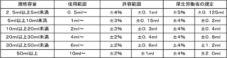
- the allowable range is a range set in advance for each standard capacity of the syringe. Thereby, inspection of mixed injection processing can be performed based on an allowable range suitable for each standard capacity of the syringe.
- the mixed injection device performs a total amount collecting process in which the total amount of the medicine stored in the medicine container is sucked by the syringe based on the preparation data by the suction control means, Shooting at the time of sampling when the bottom of the medicine container is photographed in a state where the mouth part is directed vertically upward or the mouth part of the medicine container is inclined by a predetermined angle with respect to the vertically upward direction
- the co-infusion apparatus includes container position adjusting means for adjusting a circumferential position of the medicine container held by the first driving means so that a medicine name character of the medicine container is within the photographing range.
- the co-infusion apparatus further includes rotation driving means for rotating the medicine container in the circumferential direction and container reading means for reading medicine information from the medicine container rotated by the rotation driving means. Then, after the medicine information is read by the container reading means, the container position adjusting means rotates and stops the medicine container by the rotation driving means by a preset rotation amount for each medicine container. Thereby, the character of the medicine name in the medicine container can be reliably grasped in the photographed image by the photographing means during suction.
- the co-infusion apparatus includes a syringe position adjusting unit that adjusts a circumferential position of the syringe held by the first driving unit so that characters on the scale of the syringe are within the photographing range.
- the syringe position adjustment means detects the orientation of the syringe placed in a predetermined placement position in the circumferential direction, and the first drive means causes the syringe to be within the imaging range.
- a syringe rotating means for rotating the syringe by the first driving means based on the detection result of the orientation detecting means so that the characters on the scale of the syringe are within the imaging range when moved. Conceivable. Thereby, the character of the scale of the syringe can be reliably grasped in the photographed image by the photographing device at the time of suction.
- the co-infusion apparatus includes a tray reading unit, a collating unit, and a discharge control unit.
- the tray reading means includes the drug container, the syringe of the syringe, the syringe needle of the syringe, and the syringe of the infusion container when loaded with the drug container, the syringe of the syringe, and the infusion container, Identification information is read from a recording medium included in a tray on which at least one of the injection needle of the syringe and the infusion container is placed.
- the collating means includes the contents of the preparation data previously associated with the identification information read by the tray reading means and the medicine container loaded in the co-infusion apparatus, the syringe of the syringe, the injection needle of the syringe, And at least one content of the infusion container.
- the discharge control means enables the medicine container, the syringe of the syringe, the injection needle of the syringe, or the infusion container, whose collation results by the collation means do not match, to be taken out together with the tray from a predetermined discharge port. .
- the user can take out the tray, place the correct medicine container, the syringe, or the infusion container, and reload the tray.
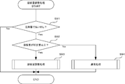
- the mixed injection device is configured to read the identification information read from the tray loaded in the mixed injection device by the tray reading unit and the discharge control unit. If the identification information read by the tray reading unit from the tray that can be taken out by the tray does not match, it is possible to further provide a notification unit that notifies that fact. Accordingly, when the tray is reloaded, it is determined whether or not the tray has been changed to another tray, so that an erroneous tray is prevented from being loaded when the tray is reloaded. It is prevented that it is processed as a medicine corresponding to.
- the co-infusion apparatus includes an on-mounting photographing unit, an interference determination unit, and a separation unit.
- the on-placement imaging unit images the device including the medicine container and the syringe placed on a predetermined device placement unit from above the device placement unit.
- the interference determination means determines whether or not there is an equipment that interferes with the other equipment only on one side in the equipment placed on the equipment placement section based on the photographing result by the on-time photographing means. Determine whether. In the state in which the separation means closes the grip portion of the first drive means for gripping the equipment when it is determined by the interference judgment means that only one side of the equipment interferes with the other equipment. Insert between two interfering equipment. Accordingly, even when the equipment interferes with the equipment placement portion, the interference can be eliminated and the equipment can be taken in.
- the co-infusion apparatus uses the equipment in which a predetermined gap is formed on both sides in the photographing result by the above-described placement photographing means, and the gap is provided on one side or both sides in the photographing result by the placement photographing means. It is conceivable to further include an uptake control means for taking in preferentially over the equipment that is not formed. Thereby, interference of the latter said equipment can be eliminated using the space formed by taking in the former said equipment first.
- the suction control means sucks medicine from the ampule with the needle tip of the syringe facing downward, and directs the needle tip of the syringe upward, and then the syringe. It is conceivable to replace the injection needle with an injection needle with a syringe filter and push out the air in the syringe by a predetermined amount. Thereby, medicine can be sucked without leaving air in the syringe, and damage to the syringe caused by impeding air after the syringe filter is submerged is prevented.
- the suction control means removes the medicine from the ampoule by a preset excess amount, pushes out the air in the syringe by a predetermined amount, and then moves the needle tip of the syringe downward. It is possible to discharge chemicals. Thereby, the influence of the volume error etc. of the injection needle of the said syringe, a syringe filter, etc. is excluded, and the error of the chemical
- the mixed injection device has an injection amount of a medicine injected from the syringe into the infusion container that is larger than a predetermined injectable amount corresponding to the infusion container, an injection for extracting air from the infusion container
- control means executes a process of extracting air from the infusion container with the syringe before the medicine is sucked with the syringe.
- the injection control means may execute a process of drawing air from the infusion container by the syringe after the medicine is sucked by the syringe and injecting the medicine from the syringe into the infusion container. Thereby, it can prevent that the said infusion container becomes a positive pressure.
- the co-infusion apparatus can suck the infusion from the infusion container with a syringe and inject it into the chemical container.
- the co-infusion apparatus includes a first robot arm, a second robot arm, a weighing device, a first control means, a second control means, a third control means, and an infusion weight acquisition means.
- the first robot arm can hold and move the chemical container.
- the second robot arm can hold and move the syringe and can operate the syringe.
- the weighing device is disposed within a movable range of the first robot arm or on the first robot arm.
- the first control means controls the first robot arm to measure the drug container with the weighing device, and controls the second robot arm to suck the infusion from the infusion container with the syringe.
- the first infusion suction step is performed in parallel.
- the second control means controls the first robot arm and the second robot arm after the first weighing step and the first infusion suction step to inject the infusion solution in the syringe into the medicine container. Perform the injection process.
- the third control means performs a second weighing step of controlling the first robot arm after the injection step and weighing the chemical container with the weighing device.
- the infusion weight acquisition means acquires the difference between the weighing result of the first weighing step and the weighing result of the second weighing step as the weight of the infusion injected into the chemical container.
- the mixed injection device configured as described above, it is possible to measure the weight of the infusion injected into the chemical container while shortening the time required for the mixed injection process.
- the first robot arm to be weighed can be weighed while holding the medicine container and the syringe and other equipment. Therefore, for example, the work process for setting the equipment in the weighing device and the work process for holding the equipment set in the weighing device again after weighing can be omitted. The required time can be greatly reduced.
- the third control means controls the second weighing step executed for one medicine container and the second robot arm, and infuses the infusion liquid into the other medicine container with the syringe. It is conceivable that the second infusion suction step for sucking from the second step is performed in parallel. Thereby, when the mixed injection process is executed using a plurality of the chemical containers, the time required for the mixed injection process can be further shortened.
- the first control means executes the second weighing process for one drug container and the first weighing process for another drug container in parallel with the second infusion suction process. It is done. Thereby, when the mixed injection process is executed using a plurality of the chemical containers, the time required for the mixed injection process can be further shortened.
- the third control unit controls the first robot arm after the second weighing step and the second weighing step. It is conceivable that the stirring step of stirring the chemical container with the stirring device is executed in parallel with the second infusion suction step. Thereby, when the mixed injection process is executed using a plurality of the chemical containers, the time required for the mixed injection process can be further shortened.
- the second control means starts the injection process on the condition that the stirring device can be used. Can be considered. Thereby, after the infusion solution is injected into the chemical container, it is left for a long time and the dissolution failure caused by the solidification of the chemical in the chemical container is suppressed.
- the co-infusion apparatus further includes a suction amount setting means for setting a chemical liquid amount to be sucked from the chemical container by the syringe based on the weight of the infusion liquid acquired by the infusion liquid weight acquisition means.
- fourth control means for changing the insertion position of the injection needle into the rubber stopper to a different position each time. It is possible to prepare further. Thereby, compared with the case where the injection needle of the syringe is inserted a plurality of times in the same place or in the vicinity of the rubber stopper of the medicine container, the occurrence of coring is suppressed, and the liquid leakage from the medicine container is suppressed. .
- the plurality of insertion positions include a plurality of positions spaced apart in the radial direction in the rubber plug.
- the insertion position in the rubber stopper can be set to a different position each time regardless of the circumferential rotation position of the chemical container.
- the co-infusion apparatus includes rotation driving means, container reading means, and container position adjusting means.
- the rotation driving unit can rotate the chemical container in the circumferential direction.
- the container reading unit can read drug information from the drug container rotated by the rotation driving unit.
- the container position adjusting means stops the rotation of the medicine container by the rotation driving means when the medicine information is read by the container reading means, or after the medicine information is read by the container reading means.
- the medicine container is rotated by the rotation driving means and stopped by the rotation amount set in advance for each medicine container.
- the fourth control means is configured such that the insertion position is different every time the injection needle is inserted into the rubber stopper based on the rotation stop position of the medicine container when rotation is stopped by the container position adjusting means. Can be set. Thereby, the insertion position in the said rubber stopper can be set to a different position each time.
- the co-infusion apparatus includes a rotation driving unit, a container reading unit, and a container position adjusting unit.
- the rotation driving means can rotate the chemical container in the circumferential direction.
- the container reading unit can read drug information from the drug container rotated by the rotation driving unit.
- the container position adjusting means stops the rotation of the medicine container by the rotation driving means when the medicine information is read by the container reading means, or after the medicine information is read by the container reading means.
- the medicine container is rotated by the rotation driving means and stopped by the rotation amount set in advance for each medicine container.
- the said 4th control means changes the rotation stop position of the said chemical
- the present invention is also a mixed injection method capable of sucking an infusion from an infusion container with a syringe and injecting the infusion into a medicine container, and (1) controlling a first robot arm capable of holding and moving the medicine container.
- the present invention is a co-infusion device capable of sucking an infusion from an infusion container with a syringe and injecting the infusion into a chemical container.
- the co-infusion apparatus includes a first robot arm, a second robot arm, a fifth control unit, and a photographing control unit.
- the first robot arm can hold and move the chemical container.
- the second robot arm can hold and move the syringe and can operate the syringe.
- the fifth control means controls the first robot arm and the second robot arm, and performs an injection step of injecting the infusion solution into the drug container with the syringe and a suction step of sucking the infusion solution from the drug container with the syringe. Execute.
- the imaging control means is capable of imaging the scale of the syringe while the infusion needle is inserted into the drug container after the infusion is sucked from the drug container in the suction step.
- the infusion liquid is sucked from the medicine container with the syringe in a state where the rubber stopper of the medicine container is directed downward and the injection needle of the syringe is directed upward, and the injection of the syringe is performed.
- a predetermined amount of air is sucked by the syringe, and then the injection needle of the syringe is used. It is conceivable that this is a step of pulling out from the chemical container.
- the imaging means after reversing the vertical positions of the syringe and the medicine container in a state of being inserted into the medicine container, before sucking a predetermined amount of air with the syringe, It is conceivable to shoot the scale.
- the present invention is a co-infusion method capable of sucking an infusion from an infusion container with a syringe and injecting the infusion into a medicine container, the first robot arm capable of holding and moving the medicine container and the syringe A second robot arm that can be moved and operated by the syringe, and an infusion process for injecting the infusion into the medicine container with the syringe, and an infusion from the medicine container with the syringe It can be regarded as a method of photographing the scale of the syringe in a state where the suction step is performed and the infusion solution is sucked from the drug container in the suction process and before the injection needle of the syringe is pulled out of the drug container. Good.
- the present invention is a co-infusion apparatus comprising a second drive means, a clamping part, a sixth control means, and a seventh control means.
- the second drive means can operate a plunger of a syringe.
- the said clamping part clamps the syringe of the said syringe in the direction perpendicular
- the sixth control means controls the second driving means to suck air from the medicine container by the syringe while the opening of the medicine container is directed upward and the tip of the syringe is directed downward.
- the first replacement step and the second replacement step of injecting the infusion solution in the syringe into the drug container are alternately performed.
- the seventh control unit determines at least one of a speed at which the second driving unit pulls the plunger, an acceleration at the start of pulling the plunger, or an amount of pulling the plunger in the first replacement step. Change according to the number of executions.
- the pulling speed, the acceleration at which the plunger is pulled, or the pulling amount of the plunger is set so that the pulling force of the plunger does not exceed the gripping force of the syringe by the holding portion. It becomes possible to adjust.
- the seventh control means gradually increases the acceleration at the start of pulling of the plunger as the number of executions of the first replacement step increases. Thereby, the time required for the injection process can be shortened while preventing the displacement of the syringe, and the time required for the mixed injection operation can be shortened.
- the seventh control means increases the pulling amount of the plunger stepwise as the number of executions of the first replacement process increases. Accordingly, since the amount of suction in the first replacement step can be increased while preventing the displacement of the syringe, the number of repetitions of the first replacement step can be reduced. The time required and the time required for the mixed injection operation can be shortened.
- the seventh control means gradually increases the pulling speed of the plunger as the number of executions of the first replacement process increases. Also in this case, the time required for the injection process can be shortened while preventing the displacement of the syringe, and the time required for the mixed injection operation can be shortened.
- the opening of the medicine container is directed upward, the tip of the syringe is directed downward, and the syringe of the syringe is sandwiched by a sandwiching portion that is sandwiched in a direction perpendicular to the operation direction of the plunger of the syringe.
- the second drive means capable of operating the plunger of the syringe is controlled, and the first replacement step of sucking air from the drug container by the syringe and the infusion solution in the syringe are injected into the drug container.
- At least one of a step of alternately performing two replacement steps, and a speed at which the second driving means pulls the plunger, an acceleration at the start of pulling the plunger, or an amount of pulling the plunger in the first replacement step can also be understood as a mixed injection method including a step of changing according to the number of times of execution of the first replacement step.
- the present invention is a co-infusion apparatus including a second drive unit, a clamping unit, a sixth control unit, and an eighth control unit.
- the second drive means can operate a plunger of a syringe.
- the said clamping part clamps the syringe of the said syringe in the direction perpendicular
- the sixth control means controls the second driving means to suck air from the medicine container by the syringe while the opening of the medicine container is directed upward and the tip of the syringe is directed downward.
- the first replacement step and the second replacement step of injecting the infusion solution in the syringe into the drug container are alternately performed.
- the eighth control means pulls the plunger at least one of a speed at which the second driving means pulls the plunger, an acceleration at the start of pulling the plunger, or an amount of pulling the plunger in the first replacement step.
- a speed at which the second driving means pulls the plunger an acceleration at the start of pulling the plunger, or an amount of pulling the plunger in the first replacement step.
- the pulling speed so that the pulling force of the plunger does not exceed the gripping force of the syringe by the clamping part, the acceleration at the start of pulling the plunger, or the plunger It becomes possible to adjust the amount of drawing.
- the opening of the medicine container is directed upward, the tip of the syringe is directed downward, and the syringe of the syringe is sandwiched by a sandwiching portion that is sandwiched in a direction perpendicular to the operation direction of the plunger of the syringe.
- the second drive means capable of operating the plunger of the syringe is controlled, and the first replacement step of sucking air from the drug container by the syringe and the infusion solution in the syringe are injected into the drug container.
- At least one of a step of alternately performing two replacement steps, and a speed at which the second driving means pulls the plunger, an acceleration at the start of pulling the plunger, or an amount of pulling the plunger in the first replacement step can also be grasped as a co-infusion method comprising a step of changing according to the expansion rate of air in the syringe.
- the pulling speed, the acceleration at which the plunger is pulled, or the pulling amount of the plunger is set so that the pulling force of the plunger does not exceed the gripping force of the syringe by the holding portion. It becomes possible to adjust.
- the present invention is a co-infusion apparatus including a cap attaching / detaching means, a second driving means, a third driving means, a sixth control means, and a ninth control means.
- the cap attaching / detaching means is used for removing the cap of the injection needle of the syringe, and can hold the cap removed from the syringe.
- the second driving means can operate the syringe.
- the third driving means can move either one or both of the syringe and the cap attaching / detaching means to an arbitrary position.
- the sixth control means controls the second driving means to suck air from the medicine container by the syringe while the opening of the medicine container is directed upward and the tip of the syringe is directed downward.
- the first replacement step and the second replacement step of injecting the infusion solution in the syringe into the drug container are alternately performed.
- the ninth control means controls the third driving means after the infusion in the syringe is injected into the medicine container by the sixth control means, and controls the third drive means to the cap held by the cap attaching / detaching means.
- the second drive means is controlled to discharge the air present in the syringe.
- the present invention is also used to remove a cap of an injection needle of a syringe, and a cap attaching / detaching means capable of holding the cap removed from the syringe, a second driving means operable to operate the syringe, and the syringe And a third injection means capable of moving either one or both of the cap attaching / detaching means to an arbitrary position, wherein the opening of the chemical container is directed upward In the state where the tip of the syringe is directed downward, the first replacement step of controlling the second drive means to suck air from the drug container by the syringe and the infusion in the syringe to the drug container A step of alternately performing a second replacement step of injecting, and after the infusion in the syringe is injected into the medicine container by the step, the third driving means is And a step of inserting the injection needle of the syringe into the cap held by the cap attaching / detaching means and controlling the second driving means to
- the present invention is a co-infusion apparatus including a first drive means, a second drive means, a tenth control means, and an eleventh control means.
- the first driving means can move either one or both of the syringe and the medicine container to an arbitrary position.
- the second driving means can operate the syringe.
- the tenth control means controls the second driving means in a state where the opening of the medicine container is directed downward and the tip of the injection needle of the syringe is directed upward, and the medicine container is controlled by the syringe. A suction process for sucking the infusion solution is performed.
- the eleventh control means controls the first driving means to gradually reduce the insertion amount of the injection needle of the syringe into the medicine container as the amount of infusion in the medicine container decreases in the suction step. . Thereby, while making the said injection needle penetrate reliably in the said chemical
- the present invention is carried out in a co-infusion apparatus comprising a first driving means capable of moving either one or both of a syringe and a medicine container to an arbitrary position and a second driving means capable of operating the syringe.
- a co-infusion apparatus comprising a first driving means capable of moving either one or both of a syringe and a medicine container to an arbitrary position and a second driving means capable of operating the syringe.
- the opening of the medicine container is directed downward and the tip of the injection needle of the syringe is directed upward, and the second driving means is controlled to control the medicine by the syringe.
- a step of performing a suction step of sucking infusion liquid from the container; and insertion of the injection needle of the syringe into the medicine container as the amount of infusion in the medicine container decreases in the suction step by controlling the first driving means.
- a mixed injection device and a mixed injection method capable of capturing an image suitable for checking the suitability of mixed injection processing in the mixed injection device are realized.
- FIG. 1 is a block diagram showing a system configuration of a co-infusion apparatus according to an embodiment of the present invention.
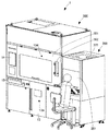
- FIG. 2 is a perspective view showing an external configuration of the co-infusion apparatus according to the embodiment of the present invention.
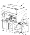
- FIG. 3 is a perspective view of the co-infusion apparatus according to the embodiment of the present invention with the main door opened.
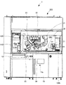
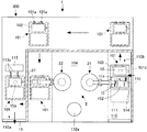
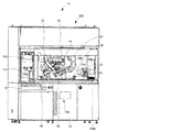
- FIG. 4 is a front view of the co-infusion apparatus according to the embodiment of the present invention with a main door and a part of the front wall removed.
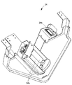
- FIG. 5 is a perspective view showing a tray used in the co-infusion apparatus according to the embodiment of the present invention.
- FIG. 6 is a perspective view of the co-infusion apparatus according to the embodiment of the present invention as viewed from below.
- FIG. 1 is a block diagram showing a system configuration of a co-infusion apparatus according to an embodiment of the present invention.
- FIG. 2 is a perspective view showing an external configuration of the co-infusion apparatus according to the embodiment of the present invention
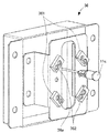
- FIG. 7 is a perspective view showing a holding portion of the first robot arm of the co-infusion apparatus according to the embodiment of the present invention.
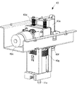
- FIG. 8 is a perspective view showing a holding portion of the second robot arm of the co-infusion apparatus according to the embodiment of the present invention.
- FIG. 9 is a schematic plan view showing a tray transport portion of the co-infusion apparatus according to the embodiment of the present invention.
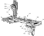
- FIG. 10 is a perspective view showing the mechanism of the tray transport unit of the co-infusion apparatus according to the embodiment of the present invention.
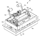
- FIG. 11 is a perspective view showing an ampoule cutter of the co-infusion apparatus according to the embodiment of the present invention.
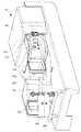
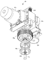
- FIG. 12 is a perspective view showing the internal configuration of the stirring device of the co-infusion apparatus according to the embodiment of the present invention.
- FIG. 13 is a perspective view showing a medicine reading unit of the co-infusion apparatus according to the embodiment of the present invention.
- FIG. 14 is a perspective view showing a needle bending detection unit of the co-infusion apparatus according to the embodiment of the present invention.
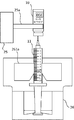
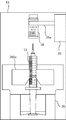
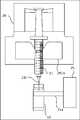
- FIG. 15 is a perspective view showing an internal structure of the injection needle attaching / detaching device of the mixed injection device according to the embodiment of the present invention.
- FIG. 16 is a perspective view showing an internal structure of the injection needle attaching / detaching device of the mixed injection device according to the embodiment of the present invention.
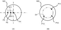
- FIG. 17 is a diagram illustrating an example of a captured image of the needle insertion confirmation camera of the co-infusion apparatus according to the embodiment of the present invention.
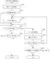
- FIG. 18 is a flowchart showing an example of the procedure of the syringe position adjustment process executed by the co-infusion apparatus according to the embodiment of the present invention.
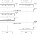
- FIG. 19 is a flowchart illustrating an example of a procedure of container position adjustment processing executed by the co-infusion apparatus according to the embodiment of the present invention.
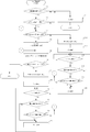
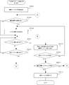
- FIG. 20 is a flowchart showing an example of the procedure of inspection control processing executed by the co-infusion apparatus according to the embodiment of the present invention.
- FIG. 21 is a diagram illustrating an example of a positional relationship between the medicine container and the syringe in the co-infusion apparatus according to the embodiment of the present invention.
- FIG. 22 is a diagram showing an example of the positional relationship between the medicine container and the syringe in the co-infusion apparatus according to the embodiment of the present invention.
- FIG. 23 is a diagram illustrating an example of a positional relationship between a medicine container and a syringe in the co-infusion apparatus according to the embodiment of the present invention.
- FIG. 24 is a diagram illustrating an example of a photographing result in the inspection control process executed by the co-infusion apparatus according to the embodiment of the present invention.
- FIG. 25 is a diagram illustrating an example of an inspection screen displayed in the inspection control process executed by the co-infusion apparatus according to the embodiment of the present invention.
- FIG. 26 is a diagram illustrating an example of an inspection screen displayed in the inspection control process executed by the co-infusion apparatus according to the embodiment of the present invention.
- FIG. 27 is a diagram illustrating an example of correspondence information that defines the relationship between the standard capacity and the allowable range of the syringe used in the co-infusion apparatus according to the embodiment of the present invention.
- FIG. 28 is a flowchart illustrating an example of a procedure of tray collation processing executed by the co-infusion apparatus according to the embodiment of the present invention.
- FIG. 29 is a flowchart showing an example of a procedure of equipment take-in processing executed by the co-infusion apparatus according to the embodiment of the present invention.
- FIG. 30 is a diagram illustrating an operation example in the equipment take-in process executed by the co-infusion apparatus according to the embodiment of the present invention.
- FIG. 31 is a diagram illustrating an operation example in the equipment take-in process executed by the co-infusion apparatus according to the embodiment of the present invention.
- FIG. 32 is a diagram illustrating an operation example in the equipment take-in process executed by the co-infusion apparatus according to the embodiment of the present invention.
- FIG. 33 is a flowchart showing an example of the procedure of the injection control process executed by the co-infusion apparatus according to the embodiment of the present invention.
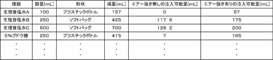
- FIG. 34 is a diagram showing an example of infusion information used in the co-infusion apparatus according to the embodiment of the present invention.
- FIG. 35 is a flowchart showing another example of the injection control process executed by the co-infusion apparatus according to the embodiment of the present invention.
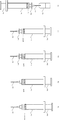
- FIG. 36 is a diagram for explaining the procedure of the drug extraction operation in the co-infusion process when using the ampoule executed by the co-infusion apparatus according to the embodiment of the present invention.
- FIG. 37 is a diagram for explaining the procedure of the drug extraction operation in the mixed injection process when the ampoule is used, which is executed by the mixed injection device according to the embodiment of the present invention.
- FIG. 38 is a flowchart illustrating an example of a procedure of a solvent amount adjustment process executed by the co-infusion apparatus according to the embodiment of the present invention.
- FIG. 39 is a block diagram showing a system configuration of a co-infusion apparatus according to another embodiment of the present invention.
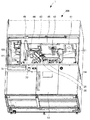
- FIG. 40 is a front view of the co-infusion apparatus according to another embodiment of the present invention with a main door and a part of the front wall removed.
- FIG. 41 is a flowchart for explaining an example of the first robot arm control process executed by the co-infusion apparatus according to another embodiment of the present invention.
- FIG. 42 is a flowchart for explaining an example of the second robot arm control process executed by the co-infusion apparatus according to another embodiment of the present invention.
- FIG. 43 is a flowchart for explaining an operation example of the first robot arm and the second robot arm in the co-infusion apparatus according to another embodiment of the present invention.
- FIG. 40 is a front view of the co-infusion apparatus according to another embodiment of the present invention with a main door and a part of the front wall removed.
- FIG. 41 is a flowchart for explaining an example of the first robot arm control process executed by
- FIG. 44 is a flowchart for explaining an operation example of the first robot arm and the second robot arm in the co-infusion apparatus according to another embodiment of the present invention.
- FIG. 45 is a diagram showing the state of the injection process and the state of the suction process in the co-infusion apparatus according to another embodiment of the present invention.
- FIG. 46 is a flowchart for explaining another example of the second robot arm control process executed by the co-infusion apparatus according to another embodiment of the present invention.
- FIG. 47 is a diagram showing an example of an image of a syringe photographed by the co-infusion apparatus according to another embodiment of the present invention.
- FIG. 48 is a diagram showing an example of an image of a syringe and a medicine container photographed by the co-infusion apparatus according to another embodiment of the present invention.
- FIG. 49 is a diagram showing an example of the insertion position of the rubber stopper of the chemical container in the co-infusion apparatus according to another embodiment of the present invention.
- FIG. 50 is a flowchart for explaining the co-infusion operation in the co-infusion apparatus according to another embodiment of the present invention.
- FIG. 51 is a flowchart for explaining the co-infusion operation in the co-infusion apparatus according to another embodiment of the present invention.
- FIG. 52 is a view for explaining a plunger positioning step in the co-infusion apparatus according to another embodiment of the present invention.
- FIG. 53 is a view for explaining a cap positioning step in the co-infusion apparatus according to another embodiment of the present invention.
- FIG. 54 is a view for explaining a cap positioning step in the co-infusion apparatus according to another embodiment of the present invention.
- FIG. 55 is a view for explaining a cap removing step in the co-infusion apparatus according to another embodiment of the present invention.
- FIG. 56 is a view for explaining a cap removing process in the co-infusion apparatus according to another embodiment of the present invention.
- FIG. 57 is a view for explaining another example of the stirring operation in the co-infusion apparatus according to another embodiment of the present invention.
- FIG. 58 is a view for explaining an injection process in the co-infusion apparatus according to another embodiment of the present invention.
- FIG. 59 is a view for explaining a suction process in the co-infusion apparatus according to another embodiment of the present invention.
- FIG. 60 is a view for explaining a suction process in the co-infusion apparatus according to another embodiment of
- the co-infusion apparatus 1 includes a co-infusion control apparatus 100, a medicine loading unit 200, and a co-infusion processing unit 300.
- a co-infusion apparatus 1 by controlling the operation of the co-infusion processing unit 300 by the co-infusion control apparatus 100, a predetermined amount of the medicine such as an anticancer agent indicated in the preparation data is accommodated.
- a co-infusion process for injecting from one or more chemical containers into the infusion container is executed.
- the mixed injection control device 100 includes a first control unit 400 and a second control unit 500 that are communicably connected.
- the first control unit 400 is provided on the medicine loading unit 200 side
- the second control unit 500 is provided on the mixed injection processing unit 300 side.
- each processing procedure of the mixed injection processing is the first control unit 400 and the second control. Any one of the units 500 may be executed.
- the mixed injection control device 100 may include one control unit or three or more control units as another embodiment.
- part or all of the processing executed by the first control unit 400 and the second control unit 500 may be executed by an electronic circuit such as an ASIC or DSP.
- the first control unit 400 can communicate with a host system 600 such as an electronic medical record system or a dispensing management system that inputs preparation data to the co-infusion apparatus 1.
- the preparation data is data for preparation generated based on prescription data or the prescription data itself.
- the prescription data includes prescription delivery date, patient ID, patient name, patient birth date, drug information (drug code, drug name, dose, etc.), dosage form information (internal use, external use, etc.), usage information (After three meals a day, etc.), medical treatment type (outpatient, hospitalization, etc.), medical department, ward, hospital room, etc. are included.
- the preparation data includes patient information, doctor information, drug information, drug prescription amount, drug container type (ampoules with drug solution, vials with drug solutions, vials with powder drugs, etc.), preparation content information (mixed injection process) ), Preparation procedure information (work contents, dissolved drug, solvent, dissolved drug amount, solvent amount, sampling amount), preparation date, prescription category, dosing date, Includes department, ward, preparation time, etc.
- the first control unit 400 is a personal computer including a CPU 401, a ROM 402, a RAM 403, a data storage unit 404, an operation unit 405, and the like.
- Various electrical components such as a display 203, a barcode reader 204, and an air cleaning device 205, which will be described later, provided in the medicine loading unit 200 are connected to the first control unit 400.
- the CPU 401 is a processor that executes processing according to various control programs.
- the ROM 402 is a non-volatile memory in which programs such as BIOS executed by the CPU 401 are stored in advance.
- the RAM 403 is a volatile memory or a non-volatile memory used for development of various control programs and temporary storage of data by the CPU 401.
- the data storage unit 404 is a hard disk or the like that stores various application programs executed by the CPU 401 and various data. Specifically, the preparation data input from the host system 600 is stored in the data storage unit 404.
- the first control unit 400 stores the identification information of the later-described tray 101 corresponding to each preparation data together with the preparation data input from the host system 600. For example, the first control unit 400 associates the preparation data with the tray 101. It is also conceivable that information indicating the correspondence between the preparation data and the tray 101 is input to the co-infusion apparatus 1 together with the preparation data.
- the data storage unit 404 stores various databases such as a medicine master, a patient master, a doctor master, a prescription classification master, a clinical department master, and a ward master.
- the medicine master includes a medicine code, a medicine name, a JAN code (or RSS), a medicine bottle code, a classification (dosage form: powder, tablet, liquid medicine, topical medicine, etc.), specific gravity, kind of medicine (ordinary medicine, Anticancer drugs, poisons, narcotics, powerful drugs, antipsychotics, therapeutic drugs, etc.), formulation changes, excipients, precautions, types of drug containers (ampoules, vials), drug capacity per drug container ( Information) such as the predetermined amount) and the weight of the drug container.
- Information drug capacity per drug container
- the data storage unit 404 stores in advance a mixed injection control program for causing the CPU 401 to execute various processes.
- the mixed injection control program may be read from a recording medium such as a CD, a DVD, a BD, or a flash memory and installed in the data storage unit 404 by a reading device (not shown) included in the first control unit 400. Good.
- the operation unit 405 includes various operation means such as a keyboard, a mouse, or a touch panel that receives various user operations in the first control unit 400.
- the second control unit 500 is a personal computer including a CPU 501, a ROM 502, a RAM 503, a data storage unit 504, an operation unit 505, and the like.
- the second control unit 500 includes a first robot arm 21, a second robot arm 22, a tray transport unit 110, a touch panel monitor 14, an IC reader 101c, an IC reader 15a, a tray, which will be described later, provided in the mixed injection processing unit 300.
- Various electrical components such as a confirmation camera 41 and a syringe confirmation camera 42 are connected.
- the CPU 501 is a processor that executes processing according to various control programs.
- the ROM 502 is a non-volatile memory in which programs such as BIOS executed by the CPU 501 are stored in advance.
- the RAM 503 is a volatile memory or a non-volatile memory used for development of various control programs by the CPU 501 and temporary storage of data.
- the data storage unit 504 is a hard disk or the like that stores various application programs executed by the CPU 501 and various data. Specifically, the data storage unit 504 stores in advance a mixed injection control program for causing the CPU 501 to execute a mixed injection process described later.
- the mixed injection control program may be read from a recording medium such as a CD, a DVD, a BD, or a flash memory and installed in the data storage unit 504 by a reading device (not shown) included in the second control unit 500. Good.
- the present invention can also be understood as an invention of the mixed injection control program for causing the CPU 401 and the CPU 501 to execute various processes in the mixed injection control device 100 or a computer-readable recording medium on which the mixed injection control program is recorded. Good. Further, the present invention may be understood as an invention of a co-infusion method for executing each procedure of the co-infusion process in the co-infusion apparatus 1.
- the operation unit 505 includes various operation means such as a keyboard, a mouse, or a touch panel for receiving various user operations in the second control unit 500.
- the medicine loading unit 200 is a clean bench including a door 201, a work table 202, a display 203, a barcode reader 204, and an air cleaning device 205. As shown in FIG. 3, the medicine loading unit 200 and the mixed injection processing unit 300 are communicated with each other through a tray insertion port 114 formed on a side surface of the mixed injection processing unit 300.
- the display 203 is a display means such as a liquid crystal display or an organic EL display that displays various types of information in response to a control instruction from the first control unit 400. Specifically, the display 203 displays preparation data and the like that are candidates for co-infusion in the co-infusion apparatus 1. Further, the barcode reader 204 reads a barcode described in a prescription or a preparation instruction, and inputs the content of the barcode to the first control unit 400. The air cleaning device 205 supplies air into the medicine loading unit 200 through a predetermined filter.
- the door 201 is provided in front of the medicine loading unit 200 and can be opened and closed in the vertical direction.
- the user performs a preparatory work for the mixed injection process executed by the mixed injection device 1 in a state where the door 201 is slightly opened and a hand is placed in the medicine loading unit 200.
- the tray 101 placed on the work table 202 has a medicine container 10, a syringe 11, and an infusion bag used in the mixed injection process executed by the mixed injection device 1. 12 (an example of an infusion container) is accommodated.
- the preparatory operation includes, for example, a loading operation in which the medicine container 10, the syringe 11, and the infusion bag 12 are placed at predetermined positions of the tray 101 and the tray 101 is loaded into the mixed injection processing unit 300. It is.
- the chemical container 10 is an ampule
- the chemical container 10 is referred to as an ampule 10A
- the chemical container 10 is referred to as a vial 10B.
- the tray 101 includes an electronic paper 101a on which a patient name and application are displayed as characters, and an IC tag 101b (recording medium) such as an RFID (Radio Frequency Identification) tag capable of reading and writing various types of information. Example). Identification information for identifying the tray 101 is stored in the IC tag 101b.
- the tray 101 has an infusion bag holder for holding the device container 102 (see FIG. 9) on which the medicine container 10 and the syringe 11 (syringe 11a, injection needle 11c) are placed, and the infusion bag 12.
- Part 103 (see FIG. 5).
- the instrument mounting part 102 and the infusion bag holding part 103 can be individually attached to and detached from the tray 101.
- the equipment mounting portion 102 is provided with a support portion 102A that supports the ampoule 10A in an inclined state.
- the ampoule 10A is set in a state where the ampoule 10A is stood diagonally by the support portion 102A. Thereby, a chemical
- the injection needle 11c of the syringe 11 and the like are set in an inclined state on the support portion 102A.
- the injection needle 11c includes an injection needle with a syringe filter.
- a piece when the neck of the ampoule 10A is folded is injected from the syringe 11 into the infusion bag 12, or the piece flows into the syringe 11.
- a syringe needle with a syringe filter is used.
- the syringe filter is a filter generally referred to as a coma filter, and has a function of preventing passage of foreign substances other than chemicals.
- a syringe filter manufactured by Nippon Pole is generally known.
- the vial bottle 10B and the syringe 11 are set in a state in which they are laid on the device mounting portion 102, as shown in FIGS. At this time, the syringe 11 is in a state where the syringe 11a and the injection needle 11c are separated.
- the arrangement form in the equipment mounting portion 102 described here is an exemplification, and the present invention is not limited to this.
- the infusion bag holding portion 103 is provided with a chuck portion 140 for fixing the mixed injection port (neck portion) of the infusion bag 12.
- the user sets the infusion bag 12 in the infusion bag holding portion 103 in a state where the infusion bag 12 is held by the chuck portion 140.
- the infusion bag holding portion 103 is provided with an engagement hole portion 103a used when the infusion bag holding portion 103 is raised and lowered.
- the tray 101 is supplied to the mixed injection processing unit 300 through the tray insertion port 114 after the medicine container 10, the syringe 11, and the infusion bag 12 are set by the user. It is also conceivable that the medicine loading unit 200 includes a loading mechanism such as a belt conveyor that automatically loads the tray 101 into the mixed injection processing unit 300.
- a main door 301, a syringe take-out door 302, a garbage storage chamber door 13, a touch panel monitor 14, a tray discharge port 15 and the like are provided on the front surface of the mixed injection processing unit 300.
- the main door 301 is opened and closed to access the mixed injection processing chamber 104, for example, when cleaning the mixed injection processing chamber 104 provided in the mixed injection processing unit 300.
- the said co-infusion apparatus 1 besides the said infusion bag 12 with which the chemical
- the syringe outlet door 302 is opened and closed when the syringe 11 is taken out from the mixed injection processing chamber 104.
- the waste storage chamber door 13 is for removing the waste from the waste storage chamber 13a in which waste such as the chemical container 10 and the syringe 11 after being used in the mixed injection processing in the mixed injection processing chamber 104 is stored. Is opened and closed. In addition, the tray discharge port 15 is opened and closed to take out the tray 101 on which the infusion bag 12 is placed after the medicine is mixedly injected by the mixed injection processing in the mixed injection processing chamber 104.
- the touch panel monitor 14 is a display unit such as a liquid crystal display or an organic EL display that displays various types of information in response to a control instruction from the second control unit 500.
- the touch panel monitor 14 can display, for example, images or videos taken by various cameras described later.
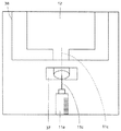
- the mixed injection processing chamber 104 includes a first robot arm 21, a second robot arm 22, an ampoule cutter 31, a stirring device 32, a mounting shelf 33, a rotating mounting portion 33 ⁇ / b> A, A medicine reading unit 34, a weighing meter 35, a needle bending detection unit 36, a mixed injection communication port 37, a needle insertion confirmation transparent window 38, a dust cover 132a, and the like are provided. Further, as shown in FIG.
- a tray confirmation camera 41, a syringe confirmation camera 42, a syringe needle attachment / detachment device 43, a needle insertion confirmation camera 44, a sterilization lamp 45, and the like are provided on the ceiling side of the mixed injection processing chamber 104.
- the first robot arm 21 and the second robot arm 22 are drive units having a multi-joint structure, and are provided in a hanging manner with a base end fixed to the ceiling side of the mixed injection processing chamber 104.
- the indirect of the first robot arm 21 and the second robot arm 22 is about 5 to 8 axes, respectively.
- each work process in the co-infusion process is executed by the double-arm first robot arm 21 and the second robot arm 22.
- the second control unit 500 individually drives the drive motors provided indirectly to the first robot arm 21 and the second robot arm 22, so that the first robot arm 21 and the second robot arm 22 are driven.
- the robot arm 22 is caused to execute each operation in the mixed injection process.
- the mixed injection processing unit 300 has, for example, a configuration including one robot arm, a configuration including three or more robot arms, or a configuration not using a robot arm as long as the mixed injection processing unit 300 can execute the mixed injection processing. It may be.
- the first robot arm 21 includes a holding portion 25 that can hold devices such as the medicine container 10 and the syringe 11, and the holding portion 25 has a predetermined movable range. It is possible to move to an arbitrary position.
- the second robot arm 22 is capable of holding equipment such as the medicine container 10 and the syringe 11, and includes a holding portion 26 that can perform operations of sucking and injecting medicine by the syringe 11.
- the first robot arm 21 and the second robot arm 22 are examples of first drive means
- the holding unit 26 is an example of second drive means.
- the second robot arm 22 can move the medicine container 10 and the syringe 11 to any position within a predetermined movable range.
- the holding portion 25 of the first robot arm 21 includes a pair of gripping claws 25a, a motor 251, two screw shafts 252, 253 rotated by the motor 251, the screw shaft 252, Nut blocks 254 and 255 screwed to 253 are provided.
- the pair of gripping claws 25a are fixed to the nut blocks 254 and 255, respectively. Then, the nut blocks 254 and 255 are moved by the rotation of the screw shafts 252 and 253, and the pair of gripping claws 25a approach and separate from each other to hold and release the holding portion 25.
- the pair of gripping claws 25a is a gripping portion having a recess suitable for holding the vial 10B and a recess suitable for holding the ampoule 10A on the tip side.
- FIG. 7 shows a state in which both the ampoule 10A and the vial bottle 10B are held, but in reality, one ampoule 10A or the vial bottle 10B is held.
- the holding portion 25 can hold the injection needle with a cap or the syringe 11 by the pair of gripping claws 25a.
- the second control unit 500 can measure the diameter of the syringe 11 according to the driving amount of the motor 251 when the syringe 11 is held by the pair of gripping claws 25a of the holding unit 25. Is possible. Accordingly, the second controller 500 can determine whether the syringe 11 is a syringe designated by the preparation content information of the preparation data.
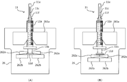
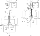
- the holding unit 26 of the second robot arm 22 includes a syringe holding unit 261, a plunger holding unit 262, and a moving unit 263.
- the syringe holder 261 includes a pair of gripping claws 261 a that hold the syringe 11 a of the syringe 11.
- the pair of gripping claws 261a are gripping portions that hold and release the syringe 11a of the syringe 11 by being close to and away from each other by a mechanism similar to the drive mechanism used in the holding portion 25.
- inclined portions 261b that are inclined downward from the upper end surface of the gripping claws 261a toward the facing surface are formed on opposing surfaces facing each other.
- the plunger holding portion 262 includes a pair of gripping claws 262a that hold the flange portion of the plunger 11b of the syringe 11.
- the pair of gripping claws 262a are gripping portions that hold and release the flange portion of the plunger 11b of the syringe 11 by being close to and separated from each other by a mechanism similar to the driving mechanism used in the holding portion 25. is there.
- a gripping claw 262b is fixed to the upper surface of each gripping claw 262a.
- Each of the gripping claws 262b is a gripping part that approaches and separates the pair of gripping claws 262a by approaching and separating, and grips not only the syringe 11 but also other devices such as the drug container 10.
- the recessed part for the collar part of the said plunger 11b to enter is formed in the upper surface of the opposing side of said pair of holding claw 262a.
- the tip ends of the pair of gripping claws 262b protrude forward from the pair of gripping claws 262a, and the pair of gripping claws 262b can easily grip equipment such as the ampoule 10A and the vial bottle 10B.
- the grip claw 262b may be provided on the grip claw 261a.
- the moving unit 263 can move the plunger holding unit 262 in the moving direction of the plunger 11b of the syringe 11.
- the moving unit 263 moves the plunger 11b by a driving mechanism such as a motor, a screw shaft rotated by the motor, a nut block screwed to the screw shaft, and a guide.
- the plunger holding part 262 is fixed to the nut block, and moves by the movement of the nut block.
- the mixed injection processing section 300 is provided with a tray transport section 110 that transports the tray 101 supplied from the tray insertion port 114 at the right end in FIG. 6 to the tray transport end section 110a at the left end. ing.
- FIG. 9 is a schematic plan view showing an example of the transport path of the tray 101 in the tray transport section 110.
- the inside of the tray transfer unit 110 is set at a positive pressure as compared with the inside of the mixed injection processing chamber 104.
- the tray transport unit 110 allows the tray 101 to pass through the rear side of the dust storage chamber 13 a located below the mixed injection processing chamber 104 and below the dust cover 132 a. It is provided to convey. Thereby, the said garbage storage chamber 13a can be accessed from the front side of the said co-infusion apparatus 1.
- the tray 101 that moves in the tray conveyance unit 110 is indicated by a two-dot chain line, and a plurality of the trays are simultaneously included in the tray conveyance unit 110. 101 does not exist.
- the tray transport unit 110 is provided with an IC reader 101c and an IC reader 15a capable of reading information from the IC tag 101b provided in the infusion bag holding unit 10 of the tray 101.
- the IC reader 101c and the IC reader 15a are RFID readers that read information from RFID tags.
- the IC reader 101c is provided in the tray conveyance start section 110b in which the tray 101 is loaded from the tray insertion port 114, and the IC reader 15a is configured to discharge the tray 101 from the tray discharge port 15. It is provided in the tray conveyance end portion 110a.
- the IC reader 101c and the IC reader 15a are examples of tray reading means.
- the second control unit 500 determines that the tray 101 is inserted into the tray conveyance start unit 110b from the tray insertion port 114 based on a sensor output (not shown)
- the IC reader 101c performs the IC operation. Information is read from the tag 101b. Further, when the second control unit 500 determines that the tray 101 is inserted into the tray conveyance termination unit 110a based on a sensor output (not shown), the information is read from the IC tag 101b by the IC reader 15a. . Then, the second control unit 500 executes a later-described tray collation process (see FIG. 28) for determining the suitability of the tray 101 according to the reading results by the IC reader 101c and the IC reader 15a.
- the tray transport is performed.
- the shutter 111 that communicates and shields the unit 110 and the mixed injection processing chamber 104 is slid in the horizontal direction.
- the equipment placement unit 102 is exposed in the mixed injection processing chamber 104.
- FIG. 9 shows a state in which the equipment placing portion 102 is exposed in the mixed injection processing chamber 104.
- the tray transport unit 110 is configured to raise and lower the equipment placement unit 102 in the tray 101 moved into the tray transport unit 110 through the tray insertion port 114.
- An elevating part 112 is provided.
- the tray lifting / lowering unit 112 lifts the equipment placing unit 102 from the bottom to the top by driving the four shafts 112a provided in a vertically movable manner, for example.
- the second control unit 500 raises the equipment placing unit 102 by the tray lifting / lowering unit 112, and then performs imaging by the tray confirmation camera 41.
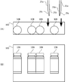
- the tray confirmation camera 41 photographs from above the medicine container 10 and the syringe 11 placed on the predetermined equipment placement unit 102.
- the tray confirmation camera 41 is an example of a photographing device when placed.
- the second control unit 500 executes an image recognition process using an image captured by the tray confirmation camera 41, and the number of the medicine containers 10 and the syringes 11 (the syringe 11a and the injection needle) indicated by the preparation data. 11c) or the like is present on the equipment placement unit 102.
- a bag lifting / lowering unit 113 that lifts and lowers the infusion bag holding unit 103 is provided in the tray transfer terminal end portion 110 a located in the left space of the mixed injection processing chamber 104.
- the second control unit 500 After the second control unit 500 transports the tray 101 to the front of the bag lifting / lowering unit 113, the second control unit 500 hooks the hook portion 113a of the bag lifting / lowering unit 113 into the engagement hole 103a from below. Then, the second control unit 500 drives the arc gear portion 113b formed with the hook portion 113a to rotate by a motor 113c, thereby raising the infusion bag holding portion 103 and opening the mixed injection port of the infusion bag 12. It is located in the mixed injection communication port 37. In addition, the second control unit 500 controls the motor 113c to drive the bag elevating unit 113 to incline the infusion bag holding unit 103 so that the mixed injection port of the infusion bag 12 faces upward or downward. can do.
- a dome-shaped light 120 and an infusion camera 121 for illuminating the infusion bag 12 conveyed to the tray conveyance end portion 110a are provided above the tray conveyance end portion 110a.
- the infusion camera 121 is provided in the center of the dome-shaped light 120 and reads a barcode attached to the surface of the infusion bag 12. Accordingly, the second control unit 500 can determine whether the infusion bag 12 is appropriate according to the barcode information read by the infusion camera 121.
- the ampoule cutter 31 As shown in FIG. 11, the ampoule cutter 31 is provided with a file part 31a, a waste tray 31b, a head insertion part 31c, a drive box 31f, a waste box 31g, and a grip part 31h.
- the file portion 31a is a member for notching the neck of the ampoule 10A, and the waste generated by the notch processing in the file portion 31a falls on the waste tray 31b.
- the first robot arm 21 holds the ampoule 10A and slides with the neck of the ampoule 10A in contact with the file portion 31a, so that the neck of the ampoule 10A is reached. Notched.
- the head insertion part 31c is positioned on the side of the head of the ampoule 10A protruding upward from the hole 31d and the hole 31d into which the head of the ampoule 10A to which the notch processing has been applied is inserted from below.
- a pusher 31e On the other hand, the drive box 31f has a cam provided therein and a drive motor for driving the cam. When the cam is driven by the drive motor, the pusher 31e is moved by the cam to the ampoule 10A. It reciprocates in the direction of approaching and separating from the head.
- the first robot arm 21 holds the ampoule 10A by the gripping claws 25a, the head of the ampoule 10A is inserted into the hole 31d from below, and the head above the neck is moved upward. To protrude. Thereafter, when the drive motor of the drive box 31f is driven by the second controller 500 and the pusher 31e is moved in the direction of pushing the head of the ampoule 10A, the pusher 31e pushes the head. To be folded. At this time, the head folded by the pusher 31e falls into the waste box 31g.
- the grip portion 31h is used by a user when the ampule cutter 31 is slid along a rail 31i (see FIG. 4) that slidably supports the ampule cutter 31.
- the agitator 32 when a medicine that needs to be dissolved such as powder (powder) is contained in the vial 10B, injects an infusion or medicine into the vial 10B to dissolve the medicine, Used when producing mixed chemicals.
- the stirring device 32 includes a roller 32a, a pressing portion 32b, a rotation support portion 32c, a support base 32d, a horizontal swing mechanism 32e, a support portion 32f, a drive motor 32g, and the like. Is provided.
- the two rollers 32a are opposed to each other with a predetermined distance therebetween.
- One roller 32a is rotatably supported, and the other roller 32a is connected to the drive motor 32g.
- Each of the rollers 32a is elongated in the axial direction, and the stirring device 32 can simultaneously stir the two vial bottles 10B placed on both ends of the roller 32a in the axial direction. .
- the pressing portion 32b is a driven roller that is used to press the vial 10B placed on the roller 32a from above and rotates as the chemical container 10 rotates.
- the rotation support portion 32c rotates the pressing portion 32b in a direction in contact with or away from the drug container 10 by a drive motor (not shown).
- the support base 32d supports the roller 32a, the pressing portion 32b, the rotation support portion 32c, and the like.
- the horizontal swing mechanism 32e has a crank mechanism, for example, and can swing the support base 32d in the axial direction of the roller 32a.
- the support portion 32f has U-shaped notches into which the neck of the vial bottle 10B is fitted at both ends in the axial direction of the roller 32a.
- the neck of the drug container 10 is engaged with the notch.
- the support base 32d is swung in the axial direction of the roller 32a by the horizontal swing mechanism 32e, the chemical container 10 swings following the swing of the roller 32a in the axial direction.
- the medicine in the medicine container 10 is stirred in the horizontal direction.
- the placement shelf 33 is used to temporarily place the medicine container 10, the syringe 11, and the like in the mixed injection process executed in the mixed injection device 1.
- the placement shelf 33 is provided at a position accessible by both the first robot arm 21 and the second robot arm 22.
- the vial bottle 10B is placed in a state where it is stood at a predetermined position.
- the placement shelf 33 is provided with an inclination holding part for holding the ampoule 10A in an inclined state, and the ampoule 10A is placed in an inclined state on the inclination holding part.
- the mounting shelf 33 is formed with a neck holding hole having a predetermined diameter, into which the neck of the syringe 11 is fitted, and the syringe 11 is in a state of only a syringe without an injection needle 11c attached. And temporarily placed with the neck facing down.
- the rotation mounting portion 33A is used in an operation for rotating the syringe 11 in the circumferential direction, and is provided at a position where the first robot arm 21 can be accessed.
- the rotation mounting portion 33A is formed with a neck holding hole having a predetermined diameter in which the neck portion of the syringe 11 is fitted, similarly to the mounting shelf 33, and the syringe 11 is a syringe needle. It is placed with the neck portion facing downward in the state of only the syringe not attached with 11c.
- the first robot arm 21 can rotate the syringe 11 by 180 degrees in the circumferential direction after placing the syringe 11 on the rotation placement portion 33A.
- the first robot arm 21 gradually rotates the syringe 11 up to 180 degrees in the circumferential direction by repeatedly executing the following (a) and (b).
- the medicine reading unit 34 reads a barcode indicating medicine information of the contained medicine described on a label attached to the medicine container 10 such as the ampoule 10A and the vial bottle 10B.
- the medicine reading unit 34 includes two rollers 34 a (an example of a rotation driving unit) and a barcode reader 34 b (an example of a container reading unit).
- the rollers 34a are arranged to face each other with a predetermined interval.
- One of the rollers 34a is rotatably supported, and the other roller 34a is connected to a drive motor (not shown).
- the two rollers 34a are driven by the drive motor to rotate the medicine container 10 placed between the rollers 34a in the circumferential direction.
- medical agent container 10 can be rotated once in the circumferential direction, the whole region of the label affixed on the said chemical
- the barcode reader 34b reads the barcode from the label of the chemical container 10 rotated by the roller 34a.
- the weighing instrument 35 is used to measure the weight of the syringe 11 in the mixed injection process executed in the mixed injection device 1, and the measurement result by the weighing instrument 35 is input to the second control unit 500.
- the weigh scale 35 is disposed within the movable range of the second robot arm 22 and measures the weight of the syringe 11 placed by the second robot arm 22.
- the needle bending detection unit 36 is formed with a long hole 36a into which the injection needle 11c of the syringe 11 can be inserted and moved.
- the needle bending detection unit 36 includes a first optical sensor 361 and a second optical sensor 362 that are arranged so that the light beams are irradiated and received with the elongated hole 36a interposed therebetween and the light beams are not parallel to each other. . Detection results from the first optical sensor 361 and the second optical sensor 362 are input to the second control unit 500.
- the second control unit 500 can detect the bending of the injection needle 11c using the position information of the injection needle 11c when blocking the light beam.
- the injection needle 11c is photographed with a camera and the needle bending is detected by image recognition on the photographed image.
- the second control unit 500 controls the infusion bag 12 with the injection needle 11c by the second robot arm 22 based on the bending amount of the injection needle 11c. The needle tip position or direction when puncturing the mixed injection port is corrected.
- the mixed injection communication port 37 is formed in a dome-shaped portion protruding outward on the side wall of the mixed injection processing chamber 104, and the dome-shaped portion of the infusion bag 12 extends vertically. A notch for passing the mixed injection port is formed. Therefore, when the infusion bag holding part 103 is raised, the mixed injection port of the infusion bag 12 is located in the mixed injection processing chamber 104.
- the needle insertion confirmation transparent window 38 is a window through which the infusion bag 12 of the tray transfer terminal portion 110a can be seen from the mixed injection processing unit 300, and the injection needle 11c of the syringe 11 is inserted into the infusion bag 12. Used when taking an image to check the status.
- the syringe confirmation camera 42 is disposed on the ceiling portion of the mixed injection processing unit 300.
- the syringe confirmation camera 42 is used to photograph the syringe 11 in order to confirm the presence and amount of the medicine sucked into the syringe 11.
- the syringe confirmation camera 42 may shoot an image in the shooting range R1 fixed in advance, but the position and size of the shooting range R1 can be arbitrarily set by being controlled by the second control unit 500. It may be changeable. Further, as will be described later, in the mixed injection device 1, the syringe 11 and the medicine container 10 are photographed at a time by the syringe confirmation camera 42, and a highly reliable inspection image is provided.
- the second control unit 500 uses the data storage unit 404, the data storage unit, and the data storage unit 404, the data storage unit, in order to check the appropriateness of the mixed injection processing executed by the mixed injection device 1, for example, with the image taken by the syringe confirmation camera 42. 504 or a storage unit such as a hard disk provided outside the mixed injection device 1. Then, the second control unit 500 causes the touch panel monitor 14 or a display device such as the display 203 to display an image captured by the syringe confirmation camera 42 during the inspection by the user.
- injection needle attaching / detaching device 43 As shown in FIGS. 15 and 16, in the injection needle attaching / detaching device 43, the needle tip of the injection needle 11c with a cap is inserted upward into the hole 43b of the chuck portion 43a in which the cut portion is formed. When the motor 43c is driven, the hole 43b of the chuck portion 43a is expanded by a cam mechanism (not shown) so that the injection needle 11c with the cap can be inserted. When the driving of the motor 43c is stopped, the holding state of the capped injection needle 11c is maintained by the spring 43d.
- the needle turning motor 43e When the needle turning motor 43e is driven, the gear 43f and the gear 43g are rotated, the chuck portion 43a is rotated, and the injection needle 11c with cap is rotated.
- the cap and the injection needle 11c are provided with ribs that come into contact with each other when the cap rotates in the circumferential direction with the cap attached to the injection needle 11c. Therefore, the injection needle 11c rotates with the cap when the cap of the injection needle 11c is rotated by the chuck portion 43a, and is attached to and detached from the syringe 11a.
- the injection needle attaching / detaching device 43 it is possible to automatically replace the injection needle 11c with a syringe filter when the ampoule 10A is used.
- the needle tip of the injection needle 11c with the cap faces upward in the injection needle attaching / detaching device 43, the distal end opening of the syringe 11a from which the injection needle 11c has been removed faces upward, and the neck opening of the syringe 11a It is possible to prevent dripping from the liquid.
- the needle insertion confirmation camera 44 photographs the infusion bag 12 located outside the mixed injection processing chamber 104 and the syringe 11 in the mixed injection processing chamber 104 so as to fit in one image.
- the second controller 500 photographs the direction of the needle insertion confirmation transparent window 38 by the needle insertion confirmation camera 44 when the injection port of the infusion bag 12 is punctured by the injection needle 11c.
- an image captured by the needle insertion confirmation camera 44 is displayed on the touch panel monitor 14, for example.
- FIG. 17 is an example of an image taken by the needle insertion confirmation camera 44. Thereby, the user can confirm whether or not the distal end side of the injection needle 11c is located in the infusion bag 12 by the captured image.
- the photographed image is stored in a storage unit such as a hard disk provided inside or outside the mixed injection device 1 for final inspection, for example.
- a storage unit such as a hard disk provided inside or outside the mixed injection device 1 for final inspection, for example.
- the germicidal lamp 45 is turned on, for example, 3 hours before the start of the mixed injection process. As shown in FIG. 6, one of the two germicidal lamps 45 is provided at a position between the first robot arm 21 and the second robot arm 22. Therefore, the amount of sterilization light blocked by the first robot arm 21 and the second robot arm 22 is reduced, and the inside of the mixed injection processing chamber 14 can be sterilized uniformly. Further, the mixed injection processing unit 300 sucks air in the mixed injection processing chamber 104 from a slit 104b (see FIGS. 3 and 4) formed in a lower portion of the side wall of the mixed injection processing chamber 104, and the mixed injection processing chamber 300.
- a slit 104b see FIGS. 3 and 4
- An exhaust system for exhausting air from an exhaust fan (not shown) provided above 104 is provided.
- an air supply system is also provided that cleans the outside air from an air inlet formed in the ceiling portion of the mixed injection processing chamber 104 and guides it to the mixed injection processing chamber 104 and the like.
- the second control unit 500 controls the first robot arm 21 and the second robot arm 22 and the like, based on the preparation data.
- the medicine is sucked from the medicine container 10 by the syringe 11 and the medicine is injected from the syringe 11 into the infusion bag 12.
- the second control unit 500 controls suction of the first robot arm 21 and the second robot arm 22 and performs processing for sucking medicine from the medicine container 10 by the syringe 11. It is an example of a means.
- the second control unit 500 When the tray 101 is supplied to the tray transport unit 110, the second control unit 500 reads the identification information of the tray 101 from the IC tag 101b of the tray 101 by the IC reader 101c. Then, the second control unit 500 opens the shutter 111 when the identification information of the tray 101 matches the identification information previously associated with the preparation data of the mixed injection process. Thereafter, the second control unit 500 raises the equipment placement unit 102 of the tray 101 by the tray lifting / lowering unit 112 of the tray transport unit 110 and exposes it to the mixed injection processing chamber 104.
- the second control unit 500 photographs the equipment placing unit 102 with the tray confirmation camera 41. Then, the second control unit 500 performs the position and orientation of the equipment such as the ampule 10A and the syringe 11 placed on the equipment placement section 102 by image recognition processing based on the image captured by the tray confirmation camera 41. To figure out. In particular, every time the ampule 10A or the syringe 11 is taken out from the device mounting unit 102, the second control unit 500 captures the device mounting unit 102 with the tray confirmation camera 41, and the latest from the captured image. The position and direction of the ampule 10A and the syringe 11 are grasped.
- the second controller 500 uses the first robot arm 21 to place the syringe 11 placed on the device placement unit 102 exposed in the mixed injection processing chamber 104 on the placement shelf 33. Temporary placement. Further, the second control unit 500 sets the ampoule 10 ⁇ / b> A placed on the equipment placing unit 102 to the medicine reading unit 34 by the first robot arm 21. Then, the second control unit 500 reads information such as the type of medicine stored in the ampoule 10 ⁇ / b> A by the medicine reading unit 34.
- the second control unit 500 sets the first injection needle 11c to the injection needle attaching / detaching device 43 and the second injection needle 11c to the placement shelf 33 by the first robot arm 21.
- the first injection needle 11c is an injection needle without a syringe filter
- the second injection needle 11c is an injection needle with a syringe filter.
- a cap is attached to the injection needle 11 c placed on the device placement portion 102, and the cap is attached and detached by the injection needle attaching / detaching device 43.
- the tray placing unit 102 is lowered by the tray lifting / lowering unit 112 of the tray transporting unit 110, thereby the tray 101.
- the second control unit 500 confirms whether or not all the devices on the device mounting unit 102 have been taken out by an image recognition process based on a photographed image by the tray confirmation camera 41.
- the second control unit 500 closes the shutter 111 and causes the tray conveyance unit 110 to convey the tray 101 to the tray conveyance termination unit 110a.
- the second control unit 500 sets the mixed injection port of the infusion bag 12 held by the infusion bag holding unit 103 of the tray 101 by the bag elevating unit 113 of the tray transport unit 110 to the mixed injection processing chamber. It is located in the mixed injection communication port 37 formed in 104.
- the second control unit 500 moves the ampule 10A set in the medicine reading unit 34 to the mounting table 33 by the second robot arm 22.
- the second control unit 500 takes out the syringe 11 from the mounting table 33 by the first robot arm 21 and sets it on the second robot arm 22.
- the second controller 500 causes the second robot arm 22 to move the syringe 11 to the syringe needle attaching / detaching device 43 to set the syringe needle 11c in the syringe 11.
- the second controller 500 causes the second robot arm 22 to move the syringe 11 to the needle bend detector 36 to detect whether the injection needle 11c is bent.
- the second control unit 500 takes out the ampoule 10A from the mounting table 33 by the first robot arm 21 and folds the head of the ampoule 10A using the ampoule cutter 31. Then, the second control unit 500 causes the ampule 10A and the syringe 11 to approach each other by the first robot arm 21 and the second robot arm 22, and moves the injection needle 11c of the syringe 11 to the ampule 10A. Insert inside. Thereafter, the second control unit 500 operates the plunger 11b with the second robot arm 22 and sucks the amount of medicine predetermined by the preparation data from the ampoule 10A with the syringe 11.
- the first robot arm 21 and the second robot arm 22 gradually tilt the posture of the ampoule 10A and the syringe 11.
- the ampoule 10A is A state in which the medicine is moved to the side of the mouth (neck) by tilting about 10 degrees with respect to the direction is formed. This makes it possible to suck up the medicine without leaving as much as possible without putting the tip of the injection needle 11c of the syringe 11 on the bottom of the ampoule 10A.
- the second controller 500 controls one or both of the first robot arm 21 and the second robot arm 22 to suck the ampule 10A and the medicine after the medicine is sucked.
- the syringe 11 is moved into the imaging range R1 of the syringe confirmation camera 42.
- the second control unit 500 when executing such movement processing is an example of movement control means.
- the second control unit 500 captures the ampule 10A and the syringe 11 at a time using the syringe confirmation camera 42, and records the captured image in the data storage unit 504 as an inspection image.
- the syringe confirmation camera 42 is an example of an imaging device during suction.
- the syringe confirmation camera 42 photographs the predetermined photographing range R1.
- the syringe control camera 42 so that the ampule 10A and the syringe 11 after the second controller 500 is moved by the first robot arm 21 and the second robot arm 22 can be photographed at a time. It is also conceivable that the shooting range R1 can be changed.
- the second control unit 500 replaces the injection needle 11 c of the syringe 11 by the first robot arm 21 and the second robot arm 22.
- the second robot arm 22 moves the syringe 11 to the injection needle attaching / detaching device 43 and attaches the cap to the injection needle 11c.
- the second control unit 500 rotates the cap with the injection needle attaching / detaching device 43 to remove the injection needle 11 c from the syringe 11.
- the removal of the injection needle 11c may be performed by rotating the cap by the first robot arm 21 and the second robot arm 22.
- the second controller 500 opens the dust cover 132a, drops the injection needle 11c held by the injection needle attaching / detaching device 43 by the first robot arm 21 into the dust storage chamber 13a, and discards it. To do. Thereafter, the second control unit 500 causes the first robot arm 21 to set the injection needle 11c with the syringe filter on the injection needle attaching / detaching device 43 from the mounting table 33. Then, the second control unit 500 moves the syringe 11 to the injection needle attaching / detaching device 43 by the second robot arm 22 and attaches the injection needle 11 c to the syringe 11.
- the second control unit 500 moves the syringe 11 to the needle bending detection unit 36 by the second robot arm 22 and detects the presence or absence of the bending of the injection needle 11c.
- the injection needle 11c is replaced when the drug is sucked from the ampule 10A and when the infusion is injected into the infusion bag 12, and the fragments of the ampule 10A are replaced with the infusion bag. 12 is prevented.
- the second controller 500 punctures the injection needle 11c of the syringe 11 into the mixed injection port of the infusion bag 12 transported to the tray transport terminal portion 110a by the second robot arm 22, The mixed drug in the syringe 11 is injected into the infusion bag 12.
- the second control unit 500 opens the dust lid 132a and drops the ampoule 10A into the dust storage chamber 13a by the first robot arm 21 and discards it.
- the second controller 500 moves the syringe 11 to the injection needle attaching / detaching device 43 by the second robot arm 22 and attaches the cap to the injection needle 11c of the syringe 11, The syringe 11 is dropped into the garbage storage chamber 13a and discarded.
- the second control unit 500 reads various images taken by the syringe confirmation camera 42 and the like from the data storage unit 504 and displays them on the touch panel monitor 14. As a result, the user can check whether or not the mixed injection process is appropriate while looking at the touch panel monitor 14.
- the second control unit 500 When the tray 101 is supplied to the tray transport unit 110, the second control unit 500 reads the identification information of the tray 101 from the IC tag 101b of the tray 101 by the IC reader 101c. Then, the second control unit 500 opens the shutter 111 when the identification information of the tray 101 matches the identification information previously associated with the preparation data of the mixed injection process. Thereafter, the second control unit 500 raises the equipment placement unit 102 of the tray 101 by the tray lifting / lowering unit 112 of the tray transport unit 110 and exposes it to the mixed injection processing chamber 104.
- the second control unit 500 photographs the equipment placing unit 102 with the tray confirmation camera 41. Then, the second controller 500 determines the position of the equipment such as the vial 10B and the syringe 11 placed on the equipment placing section 102 by the image recognition process based on the image taken by the tray confirmation camera 41. Know the direction. In particular, each time the second control unit 500 takes out the vial 10B or the syringe 11 from the instrument mounting unit 102, the second control unit 500 captures the instrument mounting unit 102 with the tray confirmation camera 41, and from the captured image. The latest position and orientation of the vial 10B and the syringe 11 are grasped.
- the second controller 500 uses the first robot arm 21 to place the syringe 11 placed on the device placement unit 102 exposed in the mixed injection processing chamber 104 on the placement shelf 33. Temporary placement.
- the second control unit 500 sets the vial 10 ⁇ / b> B placed on the device placement unit 102 to the medicine reading unit 34 by the first robot arm 21. Then, the second control unit 500 reads information such as the type of medicine stored in the vial bottle 10 ⁇ / b> B by the medicine reading unit 34.
- the tray placing unit 102 is lowered by the tray lifting / lowering unit 112 of the tray transporting unit 110, thereby the tray 101.
- the second control unit 500 confirms whether or not all the devices on the device mounting unit 102 have been taken out by an image recognition process based on a photographed image by the tray confirmation camera 41.
- the second control unit 500 closes the shutter 111 and causes the tray conveyance unit 110 to convey the tray 101 to the tray conveyance termination unit 110a.
- the second control unit 500 sets the mixed injection port of the infusion bag 12 held by the infusion bag holding unit 103 of the tray 101 by the bag elevating unit 113 of the tray transport unit 110 to the mixed injection processing chamber. It is located in the mixed injection communication port 37 formed in 104.
- the second control unit 500 moves the vial 10B set in the medicine reading unit 34 to the mounting table 33 by the second robot arm 22.
- the second control unit 500 uses the first robot arm 21 to attach and detach the injection needle 11c of the syringe 11 placed on the device placement unit 102. Set in the device 43.
- the second control unit 500 takes out the syringe 11 from the mounting table 33 by the first robot arm 21 and sets it on the second robot arm 22. Subsequently, the second controller 500 causes the second robot arm 22 to move the syringe 11 to the syringe needle attaching / detaching device 43 to set the syringe needle 11c in the syringe 11. Thereafter, the second controller 500 causes the second robot arm 22 to move the syringe 11 to the needle bend detector 36 to detect whether the injection needle 11c is bent.
- the second control unit 500 punctures the injection needle 11c of the syringe 11 into the mixed injection port of the infusion bag 12 conveyed to the tray conveyance termination unit 110a by the second robot arm 22,
- the infusion solution of the dissolution amount indicated by the preparation data is aspirated from the infusion bag 12.
- the second control unit 500 takes out the vial 10 ⁇ / b> B placed on the placing table 33 by the first robot arm 21.
- the second controller 500 causes the vial 10B and the syringe 11 to approach each other by the first robot arm 21 and the second robot arm 22, and moves the injection needle 11c of the syringe 11 to the The vial bottle 10B is punctured. Thereafter, the second controller 500 operates the plunger 11b with the second robot arm 22 to inject the infusion in the syringe 11 into the vial 10B. Thereby, the medicine in the vial bottle 10B is dissolved by the infusion solution. At this time, the posture of the syringe 11 and the vial bottle 10B is such that the injection needle 11c of the syringe 11 is directed vertically downward, and the mouth of the vial bottle 10B is directed vertically upward.
- the second controller 500 uses the first robot arm 21 to set the vial bottle 10B into which the infusion solution has been injected into the stirring device 32. Thereby, in the said stirring apparatus 32, the chemical
- the second control unit 500 takes out the vial 10B from the stirring device 32 by the first robot arm 21.
- the second control unit 500 causes the vial 10B and the syringe 11 to approach each other by the first robot arm 21 and the robot arm 22 so that the injection needle 11c of the syringe 11 is moved to the vial. Puncture 10B. Thereafter, the second controller 500 operates the plunger 11b with the second robot arm 22 to suck the mixed drug in the vial bottle 10B with the syringe 11. At this time, the posture of the syringe 11 and the vial bottle 10B is such that the mouth of the vial bottle 10B is directed vertically downward and the injection needle 11c of the syringe 11 is directed vertically upward.
- the second control unit 500 controls one or both of the first robot arm 21 and the second robot arm 22 to remove the vial 10B and the medicine after the medicine is sucked.
- the syringe 11 in the sucked state is moved into the photographing range R1 of the syringe confirmation camera 42.
- the second control unit 500 when executing such movement processing is an example of movement control means.
- the second control unit 500 captures the vial 10B and the syringe 11 at a time using the syringe confirmation camera 42, and records the captured images in the data storage unit 504 as inspection images.
- the syringe confirmation camera 42 is an example of an imaging device during suction.
- the syringe confirmation camera 42 photographs the predetermined photographing range R1.
- the syringe confirmation camera is configured so that the vial 10B and the syringe 11 can be photographed at a time after the second controller 500 is moved by the first robot arm 21 and the second robot arm 22. It is also conceivable that the photographing range R1 of 42 can be changed.
- the second controller 500 punctures the injection needle 11c of the syringe 11 into the mixed injection port of the infusion bag 12 transported to the tray transport terminal portion 110a by the second robot arm 22, The mixed drug in the syringe 11 is injected into the infusion bag 12.
- the second controller 500 opens the dust lid 132a and drops the vial 10B into the dust storage chamber 13a by the first robot arm 21 and discards it.
- the second controller 500 moves the syringe 11 to the injection needle attaching / detaching device 43 by the second robot arm 22 and attaches the cap to the injection needle 11c of the syringe 11, The syringe 11 is dropped into the garbage storage chamber 13a and discarded.
- the second control unit 500 reads various images taken by the syringe confirmation camera 42 and the like from the data storage unit 504 and displays them on the touch panel monitor 14. As a result, the user can check whether or not the mixed injection process is appropriate while looking at the touch panel monitor 14.
- the chemical contained in the vial bottle 10B may be a chemical such as a chemical solution that does not need to be dissolved.
- the mixed injection process in this case is performed by dissolving the chemical contained in the vial bottle 10B except that the step of sucking the infusion liquid from the infusion bag 12 and injecting the infusion liquid into the vial bottle 10B is not performed. Since it is the same as the mixed injection process in the case of a necessary medicine such as a powder medicine, the description is omitted.
- Second Control Unit 500 performs the following syringe position adjustment process, container position adjustment process, inspection control process, tray collation process, instrument take-in process, injection control process, and the like.
- the second control unit 500 can execute various processes described below in the mixed injection process substantially in parallel.
- the second control unit 500 captures the characters on the scale of the syringe 11 within the imaging range R1 of the syringe confirmation camera 42 when the inspection image referred to when checking the suitability of the mixed injection process is captured.
- a syringe position adjustment process for adjusting the circumferential position of the syringe 11 held by the second robot arm 22 is executed.
- the second controller 500 starts the syringe position adjustment process when an image of the device placement unit 102 is taken by the tray confirmation camera 41.
- the second controller 500 when executing the syringe position adjustment process is an example of a syringe position adjustment unit.
- FIG. 18 is a flowchart showing an example of the procedure of the syringe position adjustment process.
- step S ⁇ b> 1 the second control unit 500 determines whether the syringe 11 placed on the device placement unit 102, which is a predetermined placement position, on the basis of an image captured by the tray confirmation camera 41.
- the direction of the syringe 11a is determined.
- the second control unit 500 when executing the step S1 is an example of a direction detecting means. Specifically, a flange is provided at an end portion of the syringe 11a, and the syringe 11a placed on the device placing portion 102 is in a state in which the character of the scale is upward or downward. .
- the second control unit 500 determines that the syringe 11 has the scale letters on the syringe 11a of the syringe 11 facing upward (the scale letters facing the tray confirmation camera 41 side) or downward ( It is determined whether the device is placed on the equipment placement unit 102 in a state of being rotated 180 ° in the circumferential direction with respect to the tray confirmation camera 41 side.
- the image recognition method based on the photographed image is not particularly limited.
- the second control unit 500 identifies the syringe 11 that matches the standard size indicated in the preparation data by image matching. Then, the second controller 500 uses the OCR (optical character recognition) for the image of the syringe 11 to indicate the characters “1”, “2”,. It is determined that the scale character of the syringe 11 is upward.
- the second control unit 500 includes the reversed character image obtained by inverting the character indicating the scale in the image captured by the tray confirmation camera 41. It is also conceivable that when the reversed character image is present in the image captured by the tray confirmation camera 41, the character on the scale of the syringe 11 is determined to face downward.
- the first specific state is a state in which the scale characters of the syringe 11 are upward in the instrument mounting portion 102.
- the scale characters of the syringe 11 are In this state, the character on the scale of the syringe 11 cannot be photographed by the syringe confirmation camera 42 because it faces the holding unit 25 side.
- the characters on the scale of the syringe 11 are directed to the opposite side of the holding portion 26. The characters on the scale of the syringe 11 can be photographed by the syringe confirmation camera 42.
- step S ⁇ b> 2 the second control unit 500 branches the process depending on whether or not the syringe 11 in the device placement unit 102 is in the first specific state. Specifically, when the syringe 11 is not in the first specific state (S2: No), the process proceeds to step S3, and the second control unit 500 indicates that the rotation operation of the syringe 11 is necessary. Turn the indicated rotation flag ON.
- the rotation flag is a flag register provided in the RAM 503 of the second control unit 500.
- the process proceeds to step S4.
- step S4 the second control unit 500 waits for the timing to move the syringe 11 to the second robot arm 22 (S4: No). And when the timing which moves the said syringe 11 to the said 2nd robot arm 22 comes (S4: Yes), a process will transfer to step S5.
- the mixing injection device 1 since the syringe 11 is temporarily placed on the placement shelf 33 by the first robot arm 21, the placement shelf is moved by the first robot arm 21 in step S4. The arrival of the timing for delivery from 33 to the second robot arm 22 is monitored.
- step S5 the second controller 500 determines whether or not the rotation flag is ON. If the rotation flag is ON (S5: Yes), the process proceeds to step 6. If the rotation flag is OFF (S5: No), the process proceeds to step S7.
- step S6 the second control unit 500 controls the first robot arm 21 to rotate the syringe 11 by 180 degrees in the circumferential direction using the rotation mounting unit 33A as described above.
- the second control unit 500 when executing step S6 is an example of a syringe rotating unit.
- the direction of the said syringe 11 becomes the same direction as the case where the said syringe 11 is mounted in the said 1st specific state in the said instrument mounting part 102.
- FIG. Therefore, in the mixed injection device 1, when the syringe 11 is moved into the imaging range R1 of the syringe confirmation camera 42 by the second robot arm 22, the scale characters of the syringe 11 are moved within the imaging range R1. Can fit in.
- the structure which can rotate the said syringe 11 using the said 2nd robot arm 22 is also considered as other embodiment.
- step S7 the second control unit 500 controls the first robot arm 21 and the second robot arm 22 to move the syringe 11 from the first robot arm 21 to the second robot arm 22. Move.
- the second control unit 500 displays the name of the medicine in the medicine container 10 when the inspection image referred to when checking the suitability of the mixed injection process is taken.
- a container position adjustment process for adjusting the circumferential position of the medicine container 10 so as to be within the range is executed.
- the second control unit 500 when executing the container position adjustment process is an example of a container position adjustment unit.
- FIG. 19 is a flowchart showing an example of the procedure of the container position adjustment process.
- step S11 the second control unit 500 causes the medicine reading unit 34 to wait until the medicine information is read from the barcode of the medicine container 10 (S11: No). And if it judges that the chemical
- step S12 the second controller 500 stops the rotation of the medicine container 10 by stopping the drive motor of the roller 34a of the medicine reading section 34.
- step S ⁇ b> 13 the second control unit 500 reads a specific rotation amount corresponding to the medicine container 10. Specifically, in the data storage unit 504 of the second control unit 500, the identification from when the barcode of the chemical container 10 is read until the chemical container 10 enters a predetermined second specific state. Information on the amount of rotation is stored for each chemical container 10. In the second specific state, when the medicine container 10 is moved into the photographing range R1 of the syringe confirmation camera 42 by the first robot arm 21, the medicine name of the medicine container 10 is within the photographing range R1. It is the state of the medicine container 10 in the medicine reading unit 34 when it is accommodated.
- the second specific state is a state in which the medicine name of the medicine container 10 is directed downward (a state in which the medicine name faces the roller 34a side of the medicine reading unit 34). is there. Accordingly, when the medicine container 10 is gripped by the first robot arm 21, the medicine name of the medicine container 10 faces the opposite side of the holding portion 25, and therefore the medicine name is photographed by the syringe confirmation camera 42. It becomes possible to do.
- the second specific state is not only a state in which all of the medicine names of the medicine container 10 are within the imaging range R1, but also, for example, It is also conceivable as another embodiment that the portion is included in the photographing range R1.
- the information on the specific rotation amount is a driving amount or a driving time of a driving motor (not shown) of the roller 34 a of the medicine reading unit 34, and the information on the barcode in the circumferential direction of the medicine container 10. It is set in advance based on the distance between the position and the position of the letter of the medicine name and the rotational speed of the roller 34a. The separation distance between the position of the barcode and the position of the character of the medicine name is registered in advance in the medicine master corresponding to each medicine container 10, and the second control unit 500 is based on the distance. It is also conceivable to calculate the specific rotation amount of the medicine container 10 in the medicine reading unit 34 each time.
- the specific rotation amount is information stored in the medicine master of the data storage unit 404, and the second control unit 500 corresponds to the chemical container 10 from the first control unit 400. It is also conceivable to obtain quantity information.
- step S14 the second controller 500 controls the drive motor (not shown) of the roller 34a to rotate the chemical container 10 by the specific rotation amount and stop the roller 34a.
- the chemical container 10 is rotated by the specific rotation amount and stopped in the second specific state after the chemical information of the chemical container 10 is read by the barcode reader 34b.
- the steps S13 to S14 are performed without stopping the rotation of the medicine container 10 by the roller 34a by omitting the step S12.
- the medicine container 10 is always in the second specific state in the medicine reading section 34. Therefore, when the medicine container 10 is moved into the photographing range R1 by the first robot arm 21, the medicine name characters of the medicine container 10 are within the photographing range R1.
- the medicine name of the medicine container 10 is stored in the photographing range R1
- other information such as a barcode of the medicine container 10 or a medicine code of the medicine container 10 is used instead of the medicine name. May be adjusted in the circumferential direction of the chemical container 10 so that the value falls within the imaging range R1.
- the second control unit 500 executes the following inspection control process in order to realize an image inspection by a user of the mixed injection process.
- the second control unit 500 when executing the inspection control process is an example of a movement control unit.
- FIG. 20 is a flowchart showing an example of the procedure of the inspection control process.
- step S21 the second control unit 500 waits for the end of the suction of the medicine in the medicine container 10 by the syringe 11 (S21: No).
- step S21: Yes the process proceeds to step S22.
- step S ⁇ b> 22 the second control unit 500 moves the medicine container 10 after the medicine is sucked from the medicine container 10 by the syringe 11 and the syringe 11 that has sucked the medicine into the first robot arm.
- the syringe confirmation camera 42 is moved into the imaging range R ⁇ b> 1.
- the second control unit 500 is configured to wait until the medicine container 10 and the syringe 11 are photographed by the syringe confirmation camera 42 after the medicine is sucked from the medicine container 10 by the syringe 11. The holding state of the medicine container 10 and the syringe 11 by the first robot arm 21 and the second robot arm 22 is continued.
- the second controller 500 moves the medicine container 10 and the syringe 11 held by the first robot arm 21 and the second robot arm 22 into the imaging range R1 without releasing them.
- medical agent container 10 increases.
- the scale characters of the syringe 11 are displayed in the photographing range R1. It has been adjusted to fit within.
- the medicine container 10 is moved into the photographing range R1 by the first robot arm 21 in the container position adjustment process (see FIG. 19)
- the medicine name character of the medicine container 10 is photographed. The state is adjusted to be within the range R1.
- the second control unit 500 sets the medicine container 10 and the syringe 11 in the photographing range so that the letters of the medicine name of the medicine container 10 and the letters of the scale of the syringe 11 are aligned. Place in R1.
- the second control unit 500 includes the medicine container 10 and the syringe so that the vertical direction of the letters of the medicine name of the medicine container 10 and the letters of the scales of the syringe 11 and the vertical direction of the photographing range R1 are aligned. 11 is disposed within the photographing range R1.
- FIG. 21 is a diagram showing an example of the positional relationship between the drug container 10 and the syringe 11.
- FIG. 21 is a diagram showing a positional relationship when the medicine container 10 is the vial bottle 10B.
- the medicine container 10 is the ampule 10A, the medicine container 10 and the syringe in FIG. 11 is reversed.
- the second controller 500 arranges the medicine container 10 and the syringe 11 in the imaging range R ⁇ b> 1 in a state in which they are arranged in a direction perpendicular to the longitudinal direction of the syringe 11. Accordingly, it is possible to prevent the photographing region R1 from becoming long.
- arranging the medicine container 10 and the syringe 11 in the longitudinal direction of the syringe 11 is also conceivable as another embodiment.
- the second controller 500 controls the syringe confirmation camera 42 to photograph the photographing range R ⁇ b> 1 with the syringe confirmation camera 42. That is, the second controller 500 images the medicine container 10 and the syringe 11 that are within the imaging range R1 at a time. Thereby, compared with the case where the said syringe 11 is image
- the second control unit 500 records the image captured by the syringe confirmation camera 42 captured in step S23 in the data storage unit 504 as an inspection image.
- the second control unit 500 may store the inspection image in another server device connected to the co-infusion apparatus 1 via a communication network.
- the second control unit 500 determines whether or not the collection method corresponding to the medicine in the medicine container 10 indicated by the preparation data to be adjusted in the mixed injection process is the whole quantity collection.
- the total amount collection is a collection method in the case where all the medicines in the medicine container 10 are collected.
- the sampling method includes fractional sampling for collecting the medicine in the medicine container 10 by a predetermined amount indicated in the preparation data.
- the collection method for each medicine is registered in advance in the medicine master or the like.
- the process proceeds to step S26, and when it is determined that the sampling method is not sampling all (S26: No), the processing is performed. Control goes to step S27.
- the medicine container 10 When the medicine container 10 is the vial bottle 10B containing a medicine that needs to be dissolved, the infusion solution in the infusion bag 12 is injected into the vial bottle 10B and dissolved, and then the total amount thereof The whole quantity is extracted or a fraction is extracted.
- the medicine container 10 when the medicine container 10 is the vial 10B or the ampoule 10A containing a medicine that does not need to be dissolved, the medicine capacity indicated by the preparation data from the vial 10B or the ampoule 10A. Fractions are collected from which only chemicals are extracted.
- step S ⁇ b> 26 the second controller 500 controls the first robot arm 21 and the syringe confirmation camera 42 to photograph the bottom of the medicine container 10.
- the syringe confirmation camera 42 is an example of a photographing unit for collecting the entire amount.
- the mixed injection device 1 may be provided on the lower surface of the mixed injection processing chamber 104 separately from the syringe confirmation camera 42, and may include a container photographing camera (photographing means at the time of collecting the whole amount) for photographing the bottom of the chemical container 10. Conceivable.
- FIG. 24A and FIG. 24B are diagrams showing an example of the photographing result in step S26.
- the second controller 500 controls the first robot arm 21 so that the medicine container 10 is within the imaging range R1 of the syringe confirmation camera 42. It is conceivable that the mouth part of the medicine container 10 is shifted to a state inclined by a preset angle with respect to the vertically upward direction, and the side surface of the medicine container 10 is photographed by the syringe confirmation camera 42. Thereby, referring to the image taken by the syringe confirmation camera 42, when the medicine remains in the medicine container 10, it is possible to confirm the state where the medicine remains in the lower end portion of the medicine container 10. It is.
- the second controller 500 may take a picture of the bottom surface of the medicine container 10 with the container photographing camera in the state shown in FIG.
- the second control unit 500 controls the first robot arm 21 to place the medicine container 10 on the bottom surface within the imaging range R1 of the syringe confirmation camera 42. It is conceivable to shift the state of the medicine container 10 to fall within the photographing range R1 and photograph the bottom surface of the medicine container 10 with the syringe confirmation camera 42. Thereby, when the medicine remains in the medicine container 10, a state in which the medicine remains in the medicine container 10 is photographed. Therefore, referring to the image taken by the syringe confirmation camera 42, when the medicine remains in the medicine container 10, it is possible to confirm the state in which the medicine remains on the bottom surface of the medicine container 10. . It is also possible to confirm that no undissolved powder is left in the chemical container 10 by referring to the photographed image.
- the second control unit 500 automatically determines whether or not the medicine remains in the medicine container 10 by executing image processing based on a photographed image of the bottom of the medicine container 10, and the determination result It is also conceivable to notify the user. For example, the second controller 500 determines whether or not medicine remains depending on the presence or absence of a horizontal line on the liquid surface that appears when the medicine remains on the bottom of the medicine container 10 in the photographed image. It is possible.
- step S ⁇ b> 27 the second controller 500 controls the second robot arm 22 and the weighing meter 35 to measure the weight of the syringe 11 with the weighing meter 35.
- the weight of the syringe 11 measured here is stored in the RAM 503 of the second control unit 500 as a weight after suction.
- step S28 the second controller 500 waits for the end of the step of injecting medicine from the syringe 11 to the infusion bag 12 in the mixed injection process (S28: No). And the said 2nd control part 500 will transfer a process to step S29, if the injection
- step S ⁇ b> 29 the second controller 500 controls the second robot arm 22 and the weighing meter 35 to measure the weight of the syringe 11 with the weighing meter 35.
- the weight of the syringe 11 measured here is stored in the RAM 503 of the second controller 500 as a post-injection weight.
- step S30 the second controller 500 calculates the difference between the post-suction weight measured in step S27 and the post-injection weight measured in step S29.
- the weight of the medicine injected into the bag 12 is acquired.
- the weight of the medicine calculated here is stored in the RAM 503 of the second controller 500 as an actual weight.
- the second control unit 500 when executing such processing is an example of a chemical weight acquisition unit.
- the second control unit 500 calculates the difference between the weight of the syringe 11 before the medicine is sucked from the medicine container 10 and the weight of the syringe 11 after the medicine is sucked from the medicine container 10. It is also conceivable to obtain from 10 the weight of the medicine injected into the infusion bag 12.
- step S31 the second control unit 500 waits for the inspection start timing of the mixed injection process (S31: No). And if the start timing of the inspection of the said mixed injection process comes (S31: Yes), a process will transfer to step S32.
- the inspection start timing of the mixed injection process is, for example, a timing before the infusion bag 12 is dispensed after the mixed injection process is completed.
- the inspection start timing of the mixed injection process is a timing at which a selection operation of the mixed injection process (preparation data) to be inspected is performed on the touch panel monitor 14 after a plurality of the mixed injection processes are executed. May be.
- the second control unit 500 causes the touch panel monitor 14 to display an inspection screen D1 for performing an image inspection of the mixed injection process.
- 25 and 26 are diagrams showing an example of the inspection screen D1.
- the inspection screen D1 includes display areas R11 to R13 in which information used for inspection is displayed.
- the inspection screen D1 also includes an operation unit R14 for displaying a plurality of images to be inspected in order, an operation unit R15 for performing operations such as inspection approval, denial, and interruption.
- the drug name “methotrexate 200 mg”, the drug volume “8 mL”, and the syringe name “ ⁇ ⁇ ⁇ 10 ml syringe” shown in the preparation data are displayed.
- the scale value “8.0 mL” of the syringe 11 calculated according to the actual operation amount of the plunger 11b by the moving unit 263 of the second robot arm 22 is also displayed.
- an image taken by the syringe confirmation camera 42 in step S23 in the inspection control process is displayed as an inspection image.
- the said 2nd control part 500 when displaying the said inspection image on the said inspection screen D1 here is an example of an inspection image display means.
- the second control unit 500 when the collection method of the medicine in the mixed injection process is the whole quantity collection, the bottom surface of the medicine container 10 photographed in the step S26 according to the operation of the operation part R14. (See FIG. 24) is displayed in the display area R12 as an inspection image. Thereby, the inspector can determine whether or not the medicine remains in the medicine container 10 by referring to the image of the bottom surface of the medicine container 10 displayed in the display region R12.
- the target capacity, target weight, actual weight, and weight inspection result are displayed. Specifically, in the display area R13 shown in FIG. 25, the target volume “8.0 mL”, the target weight “7.7 to 8.3 g”, the actual weight “8.12 g”, and the weight inspection result “ ⁇ ”. Is displayed. In addition, in the display area R12 shown in FIG. 26, a target volume “8.0 mL”, a target weight “7.7 to 8.3 g”, an actual weight “8.34 g”, and a weight inspection result “ ⁇ ” are displayed. Has been.
- the target volume is a drug volume included in the preparation data, and is a value used as a control index of the operation amount of the plunger 11b by the second robot arm 22.
- the target weight is a value indicating an allowable range for the weight of the medicine calculated based on the target capacity and the specific gravity of the medicine. Note that instead of the target weight, the weight of the medicine corresponding to the target capacity (for example, 8.0 g) and the allowable error range (for example, ⁇ 3%) corresponding to the weight may be displayed. It is done.
- the actual weight is the weight of the medicine calculated in step S30 and is a value indicating the weight of the medicine actually injected into the infusion bag 12.
- the inspector can display the target capacity and the display area R12 displayed in the display area R13. It is possible to easily collate the characters on the scale of the syringe 11 in the inspection image displayed in FIG. In particular, in the inspection image, the direction of the letter of the medicine name of the medicine container 10 and the letters of the scale of the syringe 11 are aligned, so a screen that is easy for the inspector to see is realized.
- the inspector can use the chemical name character of the drug container 10 and The characters on the scale of the syringe 11 can be confirmed easily and reliably, and for example, inspection errors can be prevented.
- the inspector determines whether the actual weight, which is the weight of the medicine mixedly injected from the medicine container 10 to the infusion bag 12 by the mixed injection processing, is within the target weight range, along with the medicine name. It can be confirmed on one screen of the inspection screen D1. Further, the second control unit 500 determines whether or not the actual weight, which is the weight of the medicine mixed from the medicine container 10 to the infusion bag 12 by the mixed injection processing, is within the target weight range.
- the determination result is displayed in the display region R12 with “ ⁇ ” or “ ⁇ ”. Thereby, the inspector can grasp the weight inspection result at a glance by referring to the display area R13 displayed together with the display area R12.
- the said 2nd control part 500 when performing the judgment process which concerns here is an example of a weight inspection means.
- the background of the display region R12 may change to blue when the inspection result is “ ⁇ ” indicating appropriateness, and to red when the inspection result is “x” indicating inappropriateness.
- the second control unit 500 considers the specific gravity of the medicine when calculating the target weight (g) of the medicine from the target volume (mL) of the medicine. Specifically, the specific gravity of each medicine is stored in advance in the medicine master of the data storage unit 404 of the first control unit 400, and the second control unit 500 receives from the first control unit 400. Information on specific gravity of each of the chemicals is acquired.
- the target weight is calculated based on the specific gravity of the chemical contained in the chemical container 10.
- the medicine stored in the medicine container 10 is a medicine such as powder medicine that needs to be dissolved
- the medicine stored in the medicine container 10 is a medicine such as powder medicine that needs to be dissolved
- the second control unit 500 corresponds in advance to each combination of a medicine that needs to be dissolved and a solvent that is used to dissolve the medicine.
- the set specific gravity is stored in the data storage unit 504.
- the amount of solvent used for dissolving the medicine in the medicine container 10 is designated in advance for each kind of medicine contained in the medicine container 10. Therefore, the specific gravity corresponding to each combination of the chemical and the solvent is a specific gravity corresponding to the case where the chemical is dissolved in the amount of the solvent specified as the amount of the solvent used for dissolving the chemical.
- the said co-infusion apparatus 1 also when melt
- the allowable range is a range set in advance according to the standard capacity of the syringe 11 used in the mixed injection process, for example.
- FIG. 27 is a diagram showing an example of correspondence information that defines the relationship between the standard capacity of the syringe 11 and the allowable range.
- the allowable range is defined for each standard capacity of the syringe 11. For example, when the standard capacity of the syringe 11 is “5 ml or more and less than 10 ml”, the allowable range is “ ⁇ 3%”, and the value is “ ⁇ 0.15 ml”.
- the permissible range is not determined according to the injection amount of the medicine, but is determined according to the standard capacity of the syringe 11.
- FIG. 27 shows the permissible range defined by the Ministry of Health, Labor and Welfare as a reference, and the permissible range used in the mixed injection device 1 is set to a range smaller than the defined range of the Ministry of Health, Labor and Welfare. Yes.
- the second controller 500 converts the allowable range value into a weight based on the specific gravity of the medicine.
- the allowable range is “ ⁇ 0.3 ml” with “ ⁇ 3%”. It is.
- the specific gravity of the chemical used in the mixed injection process is “1”
- the weight-converted value of “ ⁇ 0.3 ml” that is the allowable range is “ ⁇ 0.3 g”. Therefore, as shown in FIGS. 25 and 26, in the display region R13, “7.7 to 8.3 g” is displayed as the target weight value calculated based on the weight-converted value.
- the specific gravity of the chemical is “1.1”
- the weight converted value is “ ⁇ 0.33 g”.
- “7.7 to 8.3 ml” which is the value of the allowable range corresponding to the target capacity is displayed in the display region R13.
- the second control unit 500 performs a tray collation process for determining whether or not the tray 101 and the equipment placed on the tray 101 are appropriate.
- the second control unit 500 starts the tray collation process when the sensor (not shown) detects that the tray 101 is loaded from the tray insertion port 114.
- the second control unit 500 when executing the tray matching process is an example of a matching unit.
- FIG. 28 is a flowchart showing an example of the procedure of the tray collation process.
- step S41 the second controller 500 determines whether or not identification information has been read by the IC reader 101c from the IC tag 101b of the tray 101 loaded from the tray insertion port 114. If it is determined that the identification information has been read (S41: Yes), the process proceeds to step S42. If it is determined that the identification information has not been read (S41: No), the process proceeds to step S411. Migrate to
- step S42 the second controller 500 determines whether or not the preparation data previously associated with the identification information of the tray 101 read in step S41 exists. If it is determined that the preparation data corresponding to the identification information of the tray 101 exists (S42: Yes), the process proceeds to step S43, and the preparation data corresponding to the identification information of the tray 101 exists. If it is determined not to do so (S42: No), the process proceeds to step S411.
- Step S411> the second controller 500 causes the touch panel monitor 14 to display an error display that prompts the user to remove the tray 101 from the tray insertion port 114. For example, in the error display, a message such as “Please remove the tray from the tray insertion slot” is displayed.
- the second control unit 500 The mixed injection process using the tray 101 is stopped. In the configuration in which the tray 101 is already transported to a position away from the tray insertion port 114 at the time of the step S411, the second control unit 500 moves the tray 101 to the tray insertion port in the step S411. The process of returning to 114 is executed.
- step S43 the second control unit 500 determines whether or not all the devices placed on the device placement unit 102 have been normally taken in. Specifically, the second control unit 500 uses the preparation data for the equipment such as the medicine container 10 placed on the equipment placement part 102, the syringe 11a of the syringe 11 and the injection needle 11c of the syringe 11. Is taken in by the first robot arm 21 while collating with the contents of the above.
- the equipment placement unit 102 match, it is determined that all the equipment has been taken in normally.
- step S43: Yes When it is determined that all the equipment placed on the equipment placement section 102 has been normally taken in (S43: Yes), the process proceeds to step S44 and placed on the equipment placement section 102. If it is determined that the equipment has not been normally taken in (S43: No), the process proceeds to step S431.
- the second control unit 500 collates the number of devices specified based on the captured image captured by the tray confirmation camera 41 with the number of devices indicated by the preparation data.
- the second control unit 500 collates the type of the syringe 11a specified based on the image captured by the tray confirmation camera 41 and the type of the syringe 11a included in the preparation data.
- the second control unit 500 determines the type of the injection needle 11c and the type of the injection needle 11c included in the preparation data based on the diameter of the injection needle 11c detected by the needle bending detection unit 36. Match.
- the second control unit 500 collates the drug information read by the barcode reader 34b with the drug reading unit 34 and the drug information included in the preparation data. Then, the second controller 500 determines that the equipment placed on the equipment placing section 102 has not been normally removed when the collation results do not match.
- step S43 when determining the suitability of the equipment such as the medicine container 10, the syringe 11a, and the injection needle 11c, the use of the equipment is permitted even if the types of the equipment do not completely match. Can be considered. For example, when the size of the syringe 11a is larger than the size indicated by the preparation data, it can be considered to allow the use of the syringe 11a. Thereby, even if the types of the equipment are different, if the equipment is registered in the alternative information, the mixed injection process can be executed using the equipment.
- the types of equipment that can be replaced in advance for each of the medicine container 10, the syringe 11a, and the injection needle 11c are registered in the data storage unit 504 as replacement information, and the second control unit 500
- the alternative information it is conceivable that, in consideration of the combination of the medicine container 10, the syringe 11a, and the injection needle 11c, devices that can be substituted under the conditions of each combination are registered in advance. That is, when the equipment such as the medicine container 10, the syringe 11a, and the injection needle 11c corresponds to any of a plurality of preset allowable patterns, the use of the equipment is permitted.
- step S431 the second control unit 500 puts the equipment whose collation result does not match in step S43 into a state where it can be taken out from the tray insertion port 114 together with the tray 101.
- the second control unit 500 when executing such processing is an example of the discharge control means. Specifically, the second controller 500 returns the equipment to the equipment placement section 102 and then lowers the equipment placement section 102 by the elevating section 112 to return it to the tray 101. Thereby, the equipment can be taken out from the tray insertion port 114 together with the tray 101. Further, in step S431, the second control unit 500 may make the equipment whose collation result does not match in step S43 be able to be taken out from the tray discharge port 115 together with the tray 101.
- the second control unit 500 determines that the main door 301 or the syringe with the medicine container 10 held by the first robot arm 21 when the collation result of the medicine container 10 does not match. It is conceivable to carry the sheet to a position where it can be taken out by the user, such as in the vicinity of the take-out door 302. Accordingly, the user can open the main door 301 or the syringe take-out door 302 and take out the medicine container 10 held by the holding unit 25 of the first robot arm 21. In addition, the second control unit 500 may move the chemical container 10 to a predetermined mounting unit (not shown) for return.
- the second controller 500 causes the touch panel monitor 14 to display an error display that prompts the user to remove the tray 101 from the tray insertion port 114.
- an error display For example, in the error display, a message such as “Please take out the tray from the tray insertion slot and load the correct equipment” is displayed.
- the error display includes a list of equipment that should be placed on the equipment placement unit 102.
- the second control unit 500 may display a list of equipment included in the preparation data and display the equipment whose matching results do not match so as to be identifiable. As a result, the user can easily grasp the equipment to be placed on the equipment placement section 102, and the work efficiency of the user can be improved.
- step S433 the second controller 500 determines whether or not the tray 101 has been loaded from the tray insertion port 114 according to a detection result by a sensor (not shown). If it is determined that the tray 101 has been loaded from the tray insertion port 114 (S433: Yes), the process proceeds to step S434, and it is determined that the tray 101 has been loaded from the tray insertion port 114. Until (S433: Yes), the process waits in step S433. When an operation for canceling the mixed injection process is performed on the touch panel monitor 14, the second control unit 500 ends the tray matching process.
- step S434 As in step S41, the second control unit 500 has read the identification information from the IC tag 101b of the tray 101 loaded from the tray insertion port 114 by the IC reader 101c. Judge whether or not. If it is determined that the identification information has been read (S433: Yes), the process proceeds to step S435. If it is determined that the identification information has not been read (S433: No), the process proceeds to step S436. Migrate to
- step S435 the second control unit 500 determines whether the identification information of the tray 101 matches the identification information of the tray 101 assigned to the current processing target preparation data. That is, it is determined whether or not the identification information read in step S41 matches the identification information read in step S434. Thereby, after the tray 101 can be taken out by the step S431, the identification information read by the IC reader 101c from the tray 101 loaded in the co-infusion apparatus 1 and the tray by the step S431. It is determined whether or not the identification information read by the IC reader 101c from the tray 101 from which the 101 can be taken out matches.
- S435: Yes the mixed injection process is resumed, and the process proceeds to step S43.
- the process proceeds to step S436.
- step S436 the second control unit 500 gives an error to the touch panel monitor 14 indicating that the identification information of the tray 101 does not match the identification information of the tray 101 assigned to the current preparation data to be processed. Display and inform.
- the said 2nd control part 500 when performing the process which concerns here is an example of an alerting
- Step S44> On the other hand, when it is determined that all the devices placed on the device placing unit 102 have been normally taken out (S43: Yes), in the subsequent step S44, the second control unit 500 moves the tray 101 to the tray. It is moved to the conveyance end part 110a.
- step S ⁇ b> 45 the second control unit 500 collates the preparation data with the barcode information of the infusion bag 12 read by the infusion camera 121.
- step S46 the second controller 500 branches the process according to the collation result in step S45.
- the tray collation process ends.
- the process proceeds to step S47.
- step S ⁇ b> 47 the second control unit 500 makes the infusion bag 12 whose collation result does not match in step S ⁇ b> 46 ready to be taken out from the tray discharge port 15 together with the tray 101.
- the second control unit 500 when executing such processing is an example of the discharge control means. Specifically, the second control unit 500 lowers the infusion bag holding unit 103 by the bag elevating unit 113 and returns it to the tray 101. Thereby, the infusion bag 12 can be taken out from the tray outlet 15 together with the tray 101.
- the second control unit 500 performs a process of conveying the tray 101 to the tray discharge port 15 in the step S47. Execute.
- step S ⁇ b> 48 the second control unit 500 causes the touch panel monitor 14 to display an error display that prompts the user to take out the tray 101 from the tray discharge port 15. For example, in the error display, a message such as “Tray is wrong. Remove the tray from the tray outlet, load the correct infusion bag, and insert it from the tray outlet” is displayed. As a result, the user places the correct infusion bag 12 on the tray 101 and reloads the tray 101 from the tray discharge port 15.
- step S49 the second controller 500 determines whether or not the tray 101 has been reloaded from the tray discharge port 15 according to the detection result by a sensor (not shown). If it is determined that the tray 101 has been reloaded from the tray discharge port 15 (S49: Yes), the process proceeds to step S50 until the tray 101 is reloaded from the tray discharge port 15. In the meantime (S49: Yes), the process waits in step S49. When an operation for canceling the mixed injection process is performed on the touch panel monitor 14, the second control unit 500 ends the tray matching process.
- step S50 the second control unit 500 determines whether or not the identification information has been read by the IC reader 15a from the IC tag 101b of the tray 101 loaded from the tray discharge port 15. If it is determined that the identification information has been read (S50: Yes), the process proceeds to step S51. If it is determined that the identification information has not been read (S50: No), the process proceeds to step S52. Migrate to
- step S51 the second control unit 500 determines whether or not the identification information of the tray 101 matches the identification information of the tray 101 assigned to the current processing target preparation data. That is, it is determined whether or not the identification information read in step S41 matches the identification information read in step S50. Thereby, after the tray 101 can be taken out by the step S431, the identification information read by the IC reader 101c from the tray 101 loaded in the co-infusion apparatus 1 and the tray by the step S431. It is determined whether or not the identification information read by the IC reader 101c from the tray 101 from which the 101 can be taken out matches.
- step S51: Yes when it is determined that the identification information of the tray 101 matches (S51: Yes), the mixed injection process is restarted, and the process proceeds to step S45. On the other hand, if it is determined that the identification information of the tray 101 does not match (S51: No), the process proceeds to step S52.
- step S ⁇ b> 52 the second control unit 500 gives an error to the touch panel monitor 14 that the identification information of the tray 101 does not match the identification information of the tray 101 assigned to the current preparation data to be processed. Display and inform.
- the said 2nd control part 500 when performing the process which concerns here is an example of an alerting
- the mixed injection process can be continued by loading. Further, when the tray 101 is reloaded, it is determined whether or not the tray 101 has been changed to another tray, so that an erroneous tray can be prevented from being loaded when the tray 101 is reloaded. It is prevented that it is processed as a medicine corresponding to the patient.
- the second control unit 500 executes the following equipment taking process in order to make it possible to take in the equipment even in such a case. Specifically, the second control unit 500 determines whether the medicine container 10 or the syringe 11 is in a predetermined priority condition that is specified based on the photographing result of the tray confirmation camera 41. 10 or the syringe 11 is taken in by the first robot arm 21 in order from the device mounting portion 102. The second control unit 500 starts the equipment take-in process when an image of the equipment placement unit 102 is captured by the tray confirmation camera 41.
- the second control unit 500 when executing the equipment take-in process is an example of the take-in control means.
- FIG. 29 is a flowchart showing an example of the procedure of the equipment take-in process.
- FIGS. 30 to 32 are diagrams showing an operation example in the equipment taking-in process, and FIGS. 30 (A), 31 (A), and 32 (A) show the inside of the equipment placing portion 102.
- FIG. 30 (B), FIG. 31 (B), and FIG. 32 (B) are schematic views of the state of the equipment in the equipment placement portion 102 as viewed from above. is there.
- step S ⁇ b> 61 the second control unit 500 selects other equipment or the equipment placement in the equipment placed on the equipment placement section 102 based on the image captured by the tray confirmation camera 41. It is determined whether or not there is equipment that does not interfere with the side wall of the unit 102 or the component (such as a side surface) such as the support unit 102A. If it is determined that there is no interference-free equipment (S61: Yes), the process proceeds to step S62. When it is determined that there is no equipment without interference (S61: No), the process proceeds to step S64.
- the said interference is a state in which the said equipment does not have a predetermined gap
- the second control unit 500 determines the position of each device placed on the device placement unit 102 as information on the medicine container 10, the syringe 11a, and the injection needle 11c included in the preparation data. Identify based on. For example, the second control unit 500 specifies the position of each device by image matching between an image registered in advance for each device and the captured image.
- step S62 the second control unit 500 controls the first robot arm 21 and takes in the equipment determined to have no interference in step S61.
- the rightmost vial 10B among the plurality of vials 10B has a sufficient gap on both sides, so that the vial 10B is preferentially taken in by the first robot arm 21. It is.
- step S ⁇ b> 63 the second control unit 500 photographs the instrument mounting unit 102 after the instrument is taken in in step S ⁇ b> 62 with the tray confirmation camera 41.
- step S64 the second control unit 500 determines whether or not the equipment remains in the equipment placement unit 102 based on the image taken by the tray confirmation camera 41 in step S63. .
- the second control unit 500 determines the presence / absence of equipment in the equipment placement unit 102 based on an image captured by the tray confirmation camera 41.
- the process is returned to step S61.
- the equipment take-in process ends.
- step S611 the second control unit 500 determines that only one side of the equipment placed on the equipment placing unit 102 is the other based on the photographed image taken by the tray confirmation camera 41. It is determined whether there is an equipment that interferes with the equipment.
- the second control unit 500 when executing such processing is an example of interference determination means.
- the process proceeds to step S612. If it is determined that there is no equipment that interferes with other equipment on only one side (S611: No), the process proceeds to step S613.
- Step S612 the second control unit 500 determines that only one side of the equipment placed on the equipment placement unit 102 in step S611 interferes with the other equipment. Execute the process to solve the problem.
- the second control unit 500 when executing such processing is an example of a separation unit.
- the second control unit 500 is inserted between the two interfering devices with the gripping claws 25a of the first robot arm 21 gripping the device closed. Accordingly, the two devices are separated from each other by moving the device in contact with the gripping claws 25a.
- the first robot arm 21 is used.
- the process may be executed using the second robot arm 22. Considered as a form.
- FIG. 31 shows a state where there is the vial 10B in which only one side of the plurality of vials 10B interferes with the other vial 10B.
- the second controller 500 inserts the vial 10B between the two vials 10B with the gripping claws 25a of the first robot arm 21 closed. Move it away.
- the two vial bottles 10B that have been in contact with each other are separated from each other, so that the vial bottle 10B can be taken in step S62.
- the gripping claw 25a is in contact with the anti-slip portion 25b for preventing the device from slipping on the surface for gripping the device, and when the device is moved to the outer surface of the surface for gripping the device.
- An inclined portion 25c is provided.
- the anti-slip portion 25b has a surface shape having a high friction coefficient (high resistance), for example. Further, the anti-slip portion 25b may be affixed with a sheet having a high friction coefficient.
- the inclined portion 25c is formed to move the equipment while suppressing a load applied to the equipment when the gripping claws 25a are lowered toward the equipment and come into contact with the equipment.
- the gripping claws 25a are inserted between the two devices in a closed state, sliding between the anti-slip portion 25b and the devices is prevented, and the chemical container 10 peeling of the label or damage to the equipment is prevented. Further, since the tip of the gripping claw 25 has an acute angle due to the inclined portion 25c, even when the diameter of the equipment is small, the equipment can be inserted between the equipment without being sandwiched between the placement surfaces. .
- the amount of descending when the gripping claws 25a are inserted between the two devices is set in advance from the upper end of one of the devices according to the diameter of the device. For example, it is conceivable that the descending amount is 1 ⁇ 2 of the diameter of the larger one of the two devices.
- the equipment can be separated and unnecessary pressure is prevented from acting on the equipment.
- the second control unit 500 identifies a device having a wide space in the direction of separation from the two devices based on an image captured by the tray confirmation camera 41, and the gripping is first performed on the identified device. It is also conceivable to lower the gripping claws 25a to a position shifted from the center of the two devices so that the claws 25a come into contact with each other.
- the second control unit 500 is a case where there is an instrument that interferes with a component of the instrument mounting unit 102 only on one side, and there is a gap between the instrument and the component of the instrument mounting unit 102.
- the gripping claws 25a are inserted between the equipment and the constituent elements of the equipment placement section 102 when the threshold is equal to or greater than a predetermined threshold.
- the threshold value is set in advance corresponding to each diameter of the device as a value that allows the device to be separated from the component without the gripping claw 25a pressing the device, for example.
- step S613 the second control unit 500 satisfies the stop condition for stopping the taking-in of the equipment from the equipment placing unit 102 based on the photographed image taken by the tray confirmation camera 41. Judge whether or not. Specifically, the discontinuation condition is that all the devices placed on the equipment placing portion 102 have one side or both sides that interfere with the constituent elements of the equipment placing portion 102, or both sides have other equipment. It corresponds to the equipment which interferes.
- the process proceeds to step S614, and when it is determined that the cancellation condition is not satisfied (S613: No), processing is performed. Returns to step S61.
- the stop condition includes that a preset stop time has elapsed since the start of the equipment take-in process, and the process moves to step S614 even when the stop time has passed.
- the process may proceed to step S614. Is considered.
- step S614 the second control unit 500 causes the touch panel monitor 14 to display an error and stops taking in the equipment from the equipment placement unit 102.
- the error display includes a message that the equipment in the equipment placement section 102 cannot be taken in normally, and a message that prompts the user to remove the equipment placement section 102 from the tray insertion port 114.
- the second control unit 500 returns the equipment placing unit 102 to the tray 101 by the tray lifting / lowering unit 112 so that the tray 101 can be taken out from the tray insertion port 114.
- one of the vial bottles 10 ⁇ / b> B is in contact with the side wall of the instrument mounting unit 102.
- the vial bottle 10B that contacts the side wall of the device mounting portion 102 is discharged from the tray insertion port 114 together with the tray 101 without being taken in. Accordingly, the user can reload the tray 101 from the tray insertion port 114 after eliminating the interference of the equipment placed on the equipment placement portion 102 of the tray 101.
- the second control unit 500 may use the equipment in which a predetermined gap is formed on both sides in the photographing result by the tray confirmation camera 41, and the gap on one side or both sides in the photographing result by the tray confirmation camera 41. Is preferentially taken in over the above-mentioned equipment not formed. Therefore, in the co-infusion apparatus 1, it is possible to separate the equipment using the space formed in the equipment placement portion 102 when the equipment that does not interfere with other equipment is first taken in.
- FIG. 33 is a flowchart showing an example of the procedure of the injection control process.
- step S71 the second control unit 500 specifies an injectable amount corresponding to the infusion bag 12.
- an injectable amount corresponding to the infusion bag 12.
- Infusion information is stored.
- the second control unit 500 specifies the injectable amount without air bleeding and the injectable amount with air bleeding corresponding to the infusion bag 12 based on the infusion information.
- the injectable amount is a value set in advance as an injection amount that does not cause a positive pressure in the infusion bag 12.
- FIG. 34 is a diagram showing an example of the infusion information.
- the type of the infusion bag 12 is “physiological saline A”
- the volume of the solvent already contained is “100 mL” and the full volume (maximum capacity) is “157 mL”.
- the injectable amount without air venting is “0 mL”, and the injectable amount without air venting is “57 mL”.
- the type of the infusion bag 12 is “physiological saline B”
- the volume of the solvent already contained is “250 mL”
- the full amount (maximum capacity) is “425 mL”
- there is no air venting is no air venting.
- the injectable amount is “117.6 mL”, and the injectable amount with air bleeding is “175 mL”.
- the shape of the infusion bag 12 is a “plastic bottle” having low elasticity such as “physiological saline A”
- the shape of the infusion bag 12 is Compared to the case of a “soft bag” having high elasticity like “physiological saline B”
- the injectable amount without air venting and the injectable amount with air venting are small.
- step S72 the second controller 500 determines that the amount of medicine to be injected from the syringe 11 into the infusion bag 12 is based on the preparation data, and the infusion bag 12 specified in step S71 is not vented. It is determined whether or not the injectable amount is exceeded. If it is determined that the injection amount exceeds the possible injection amount without error (S72: Yes), the process proceeds to step S73, and the injection amount does not exceed the injection allowable amount without error. If determined (S72: YeNo), the process proceeds to step S75.
- step S73 the second controller 500 determines that the amount of medicine injected from the syringe 11 into the infusion bag 12 is based on the preparation data. It is determined whether or not the injectable amount is exceeded. If it is determined that the injection amount does not exceed the injection possible amount without error (S73: YeNo), the process proceeds to step S74. On the other hand, if it is determined that the injection amount exceeds the possible injection amount with error removal (S73: Yes), the second control unit 500 ends the injection control process after displaying an error or the like.
- the second control unit 500 may determine whether or not the injectable amount is exceeded in step S72 and step S73 in consideration of the amount of infusion extracted from the infusion bag 12. For example, it is conceivable that the second control unit 500 makes the determination using the value obtained by subtracting the amount of infusion extracted from the infusion bag 12 from the injectable amount as the injectable amount. Thereby, for example, unnecessary air venting processing (S74) is prevented.
- step S ⁇ b> 74 the second controller 500 controls the second robot arm 22 to extract air from the infusion bag 12 using the syringe 11 before the medicine is sucked by the syringe 11. .
- the second control unit 500 controls the motor 113c to drive the bag elevating unit 113 to incline the infusion bag holding unit 103 so that the mixed injection port of the infusion bag 12 faces upward. To do. Thereby, air can be collected at the mixed injection port of the infusion bag 12.
- the second controller 500 inserts the injection needle 11c of the syringe 11 into the infusion bag 12 and pulls the plunger 11b of the syringe 11 by the second robot arm 22 to pull the plunger 11b into the infusion bag 12.
- Remove the air is, for example, an amount corresponding to the volume of the amount of drug injected from the syringe 11 into the infusion bag 12 in the mixed injection process. It is also conceivable that the amount of air extracted here is a preset constant amount.
- Step S75 the second control unit 500 waits for the end of the step of sucking the medicine from the medicine container 10 using the syringe 11 in the mixed injection process (S75: No).
- the medicine suction step from the medicine container 10 using the syringe 11 is completed (S75: Yes)
- the process proceeds to step S76.
- step S ⁇ b> 76 the second controller 500 injects a medicine from the syringe 11 into the infusion bag 12 by controlling the second robot arm 22. At this time, even if the amount of medicine injected from the syringe 11 exceeds the co-injectable amount of the infusion bag 12 without air bleeding, the air is extracted in advance by the step S74. Therefore, the inside of the infusion bag 12 is prevented from becoming a positive pressure, and the ejection of medicine from the infusion bag 12 is prevented.
- the second control unit 500 executes the injection control process shown in FIG. 35 instead of the injection control process (see FIG. 33). Specifically, in the injection control process shown in FIG. 35, instead of the step S74, the following steps S81 to S83 are executed, whereby the medicine is sucked by the syringe 11, and the infusion bag is transferred from the syringe 11. The injection of air from the infusion bag 12 by the syringe 11 is subsequently performed after the medicine is injected into the body 12.
- step S ⁇ b> 81 the second control unit 500 sets an extraction flag indicating that it is necessary to extract air from the infusion bag 12 to ON. That is, at this time, the extraction of air from the infusion bag 12 is not executed.
- the extraction flag is a flag register provided in the RAM 503 of the second control unit 500.
- Step S82> the second control unit 500 determines whether the extraction flag is ON. Judge whether or not. If the extraction flag is ON (S82: Yes), the process proceeds to step 83. If the extraction flag is OFF (S82: No), the injection control process ends.
- step S ⁇ b> 83 the second control unit 500 continuously removes air from the infusion bag 12 while the injection needle 11 c of the syringe 11 is inserted into the infusion bag 12.
- the infusion bag 12 of the injection needle 11c of the syringe 11 is compared with a case where air is extracted from the infusion bag 12 in advance. The number of insertions can be reduced.
- the imaging timing by the needle insertion confirmation camera 44 is from when the medicine is injected into the infusion bag 12 from the syringe 11 until the extraction of the air is started. It is possible. Thereby, the state in which the plunger 11b of the syringe 11 is pushed to the end can be photographed by the needle insertion confirmation camera 44.
- the injection control process is executed, so that the injection amount of the medicine to be injected from the syringe 11 into the infusion bag 12 is predetermined corresponding to the infusion bag 12.
- the amount is larger than the injectable amount without air removal, air is extracted from the infusion bag 12. Therefore, the infusion bag 12 does not become a positive pressure, and the ejection of medicine from the infusion bag 12 can be prevented.
- the second control unit 500 controls the ampule according to the following procedure by controlling the injection needle attaching / detaching device 43, the first robot arm 21, the second robot arm 22, and the like.
- the medicine extraction operation from 10A is executed. Thereby, the medicine is sucked from the ampoule 10A by the syringe 11 without leaving air in the syringe 11.
- FIG. 36 and FIG. 37 are diagrams for explaining the procedure of the medicine extraction operation in the mixed injection process when the ampoule 10A is used. Note that description of detection of the needle bending of the injection needle 11c is omitted.
- step S101 as shown in FIG. 36A, the injection needle 11c without the syringe filter is attached to the syringe 11 by the injection needle attaching / detaching device 43 and the second robot arm 22. At this time, air does not exist in the syringe 11a, but air exists between the syringe 11a and the tip of the injection needle 11c.
- step S102 As shown in FIG. 36 (B), after the needle tip of the injection needle 11c of the syringe 11 is inserted downward into the ampule 10A by the second robot arm 22, the syringe The plunger 11b is pulled to suck the drug from the ampoule 10A. At this time, air existing between the syringe 11a and the tip of the injection needle 11c flows into the syringe 11a. At this time, the initial air amount sucked into the syringe 11a is defined as ⁇ .
- the second controller 500 pulls the plunger 11b by a correction amount S larger than the volume Ln when the volume of the medicine to be collected from the ampoule 10A is Ln based on the preparation data.
- the scale of the syringe 11a of the syringe 11 is the capacity Ln + the correction amount S.
- the correction amount S includes the initial air amount ⁇ , the adjustment surplus amount ⁇ , and the filter correction amount ⁇ .
- the syringe 11 (syringe 11a and injection needle 11c) contains an amount of medicine corresponding to the volume Ln + the correction amount S ⁇ the initial air amount ⁇ .
- the adjustment excess amount ⁇ is a value larger than the capacity in the injection needle 11c, and is a value set in advance as an amount used for adjusting the amount of medicine in the syringe 11a in step S109 described later. is there.
- the filter correction amount ⁇ is a value corresponding to the volume in the injection needle 11c with a syringe filter attached to the syringe 11, and the injection needle is injected after a drug is injected from the syringe 11 into the infusion bag 12. It is a value set in advance as the amount of medicine remaining in 11c.
- air is drawn by a predetermined amount C to prevent ejection at the end of extraction of the medicine from one ampule 10A, and the scale of the syringe 11a The predetermined amount C is further added.
- step S103 As shown in FIG. 36C, the syringe 11 is moved upward by the second robot arm 22, and the injection needle 11c is lifted from the liquid surface of the ampoule 10A. The plunger 11b is pulled by the predetermined amount c1. Thereby, the liquid leakage from the syringe 11 is prevented. At this time, the scale of the syringe 11a of the syringe 11 is the capacity Ln + the correction amount S + the constant amount c1.
- step S104 As shown in FIG. 37A, the tip of the injection needle 11c of the syringe 11 is directed upward by the second robot arm 22, and the plunger 11b is pulled by a predetermined fixed amount c2.
- the fixed amount c2 is an amount that allows at least all of the medicine in the injection needle 11c to be taken into the syringe 11a.
- medical agent in the injection needle 11c of the said syringe 11 is taken in in the said syringe 11a, and the ejection of the chemical
- the scale of the syringe 11a of the syringe 11 is the capacity Ln + the correction amount S + the fixed amount c1 + the fixed amount c2.
- step S105 the syringe 11 is rotated once or a plurality of times around the rotation axis parallel to the horizontal direction by the second robot arm 22, and then the needle tip of the injection needle 11c of the syringe 11 is moved upward. Turn to. As a result, air present as bubbles in the syringe 11 is collected upward in the syringe 11. It is also conceivable to collect the air in the syringe 11 upward by swinging the syringe 11 or oscillating the syringe 11.
- step S105 the working time can be shortened by removing the air from the syringe 11a before replacing the injection needle 11c with the injection needle 11c with the syringe filter.
- the scale of the syringe 11a of the syringe 11 is the capacity Ln + the correction amount S.
- step S107 as shown in FIG. 37C, the injection needle 11c of the syringe 11 is replaced with the injection needle 11c with the syringe filter by the injection needle attaching / detaching device 43 and the second robot arm 22. Replace with. At this time, the injection needle 11c is covered with a cap.
- the injection needle 11c with the syringe filter includes a syringe filter 11d, and the entire capacity of the injection needle 11c is equal to that of the needle portion of the injection needle 11c. This is a value obtained by adding the volume of the syringe filter 11d to the volume.
- step S108 the second robot arm 22 causes the tip of the injection needle 11c of the syringe 11 to face upward and is larger than the initial air amount ⁇ .
- the plunger 11b is pushed in by an amount smaller than the correction amount S to push out a predetermined amount f of air.
- the scale of the syringe 11a of the syringe 11 is the capacity Ln + the correction amount S ⁇ the predetermined amount f.
- the second robot arm 22 removes the cap of the injection needle 11 c by the injection needle attaching / detaching device 43. Further, the cap of the injection needle 11c may be removed in step S109 described later.
- step S109 As shown in FIG. 37 (E), the second robot arm 22 is inserted into the space inside the ampule 10A with the tip of the injection needle 11c of the syringe 11 facing downward, Excess medicine in the syringe 11 is discharged by pushing the plunger 11b until the scale of the syringe 11a reaches a position corresponding to the capacity Ln.
- the second control unit 500 can specify the scale of the syringe 11 a according to the position of the moving unit 263 of the second robot arm 22.
- the medicine When the medicine is extracted from the ampoule 10A by the syringe 11 by such a procedure, the medicine corresponding to the capacity Ln is accommodated in the syringe 11a of the syringe 11, and the medicine is contained in the injection needle 11c. It becomes a full state. Therefore, since no air remains in the syringe 11a of the syringe 11, the syringe filter 11d is prevented from being damaged when the medicine is injected from the syringe 11 into the infusion bag 12.
- the syringe 11 is filled with medicine in the injection needle 11c in addition to the syringe 11a, when the medicine is injected from the syringe 11 into the infusion bag 12, the syringe 11 is filled. Although the medicine remains in the injection needle 11c, the medicine of the volume Ln stored in the syringe 11a is injected into the infusion bag 12.
- the syringe 11a, the injection needle 11c, and the syringe are used in order to discharge the unnecessary amount of drug at the end after the adjustment amount ⁇ of drug is sucked into the volume Ln. The influence of volume error such as the filter 11d can be eliminated.
- FIG. 38 is a flowchart showing an example of the syringe dispensing process executed by the second control unit 500.
- the syringe dispensing process is executed during the preparation data issuing operation.
- the second control unit 500 determines whether or not it is necessary to dispense the medicine stored in the medicine container 10 in the state where the syringe 11 is filled based on the preparation data. To do. If it is determined that the syringe 11 will pay out (S91: Yes), the process proceeds to step S92.
- step S92 the second control unit 500 determines whether or not the amount of solvent is equal to or greater than the capacity of the chemical container 10. If the amount of solvent is not equal to or greater than the capacity of the chemical container 10 (S92: No)
- step S94 a normal process of sucking the medicine in the medicine container 10 by the syringe 11 is executed. In addition, when it is necessary to dissolve or dilute the drug in the drug container 10 in the normal process, after the process of injecting the solvent extracted from the infusion bag 12 with the syringe 11 into the drug container 10 is executed. The medicine in the medicine container 10 is sucked by the syringe 11.
- the second control unit 500 executes a solvent amount adjustment process in step S93.
- the solvent amount adjustment process the drug in the drug container 10 is sucked by the syringe 11 as in the normal process. Thereafter, the syringe 11 further sucks the solvent in the infusion bag 12 by the syringe 11. The amount of solvent in 11 is adjusted.
- the medicine to be prepared in the co-infusion apparatus 1 includes a medicine (hereinafter referred to as “light-shielding medicine”) such as an anticancer agent (for example, dacarbacin) that requires light shielding.
- a light-shielding container having a light-shielding property is used as the chemical container 10 in which the light-shielding drug is accommodated, and is injected into the infusion bag 12 from the light-shielding container using the syringe 11 in the co-infusion apparatus 1.
- the light shielding agent is exposed to light.
- the infusion bag 12 is stored in a light-shielding bag having a light-shielding property after the light-shielding agent is injected into the infusion bag 12.
- the infusion bag 12 taken out from the co-infusion apparatus 1 is manually stored in a light-shielding bag. Therefore, in the mixed injection device 1, the light-shielding agent in the infusion bag 12 after being injected from the syringe 11 into the infusion bag 12 until the infusion bag 12 is accommodated in the light-shielding bag. The problem of being exposed to light.
- the co-infusion apparatus 1 has a light-shielding agent processing function capable of suppressing as much as possible the time during which the light-shielding agent is exposed to light in the co-infusion processing when the light-shielding agent is a preparation target.
- the medicine master stored in the data storage unit 404 includes information indicating whether each medicine is the light-shielding medicine. Accordingly, the first control unit 400 and the second control unit 500 can determine whether or not the preparation target drug included in the preparation data is the light shielding drug.
- the said 1st control part 400 is the object of the said co-infusion process with respect to the said 2nd control part 500. Notify that it is a sunscreen. Accordingly, the second control unit 500 turns off the illumination device (not shown) in the mixed injection processing chamber 104 before the tray 101 on which the light shielding agent is set is transferred into the mixed injection processing chamber 104. Let Thereby, when the mixed injection process of the said light shielding agent is performed in the said mixed injection processing chamber 104, the light which hits the said light shielding agent is suppressed.
- the mixed injection device 1 in the mixed injection processing chamber 104, the state of the light-shielding container (drug container 10), the syringe 11, the infusion bag 12, and the like is photographed in order to perform an image inspection of the mixed injection processing. Therefore lighting is necessary.
- the second controller 500 temporarily turns on the illumination device (not shown) in the mixed injection processing chamber 104 only when the inspection image is taken. Thereby, it becomes possible to perform the image inspection of the mixed injection process of the light shielding agent while suppressing the light irradiation to the light shielding agent.
- the user when the user sets the infusion bag 12 in the tray 101, the user places the infusion bag 12 in the light-shielding bag in advance, and sets the infusion bag 12 in the state where only the mixed injection port of the infusion bag 12 is exposed. It is possible to do. Thereby, the light which hits the said light shielding agent after inject
- information such as a bar code attached to the surface of the infusion bag 12 cannot be read by the infusion camera 121 of the tray transfer terminal portion 110a. Therefore, it can be considered that the second control unit 500 turns off the collation function of the infusion bag 12 using the barcode.
- the second control unit 500 turns off the dome-shaped light 120 when the mixed injection process of the light shielding agent included in the preparation data is executed. Thereby, the light which hits the said light shielding agent in the said tray conveyance termination
- the user sets the infusion bag 12 in the tray 101 without storing it in the light shielding bag as usual.
- the second controller 500 illuminates the dome-shaped light 120 and photographs the barcode of the infusion bag 12 with the infusion camera 121 before the light shielding agent is injected into the infusion bag 12. Then, the dome-shaped light 120 can be turned off. Thereby, irradiation of the light with respect to the said light shielding agent after inject
- the weight of the drug sucked from the drug container 10 by the syringe 11 and injected into the infusion bag 12 is the syringe. 11 based on the weight.
- the second controller 500 calculates the difference between the weight of the syringe 11 after sucking the medicine from the medicine container 10 and the weight of the syringe 11 after injecting the medicine into the infusion bag 12. The weight of the medicine sucked from the medicine container 10 by the syringe 11 and injected into the infusion bag 12 is calculated.
- the second control unit 500 calculates the difference between the weight of the syringe 11 before the drug is sucked from the drug container 10 and the weight of the syringe 11 after the drug is sucked from the drug container 10. It may be calculated as the weight of the medicine injected from the container 10 into the infusion bag 12.
- the weight of the infusion sucked from the infusion bag 12 by the syringe 11 and injected into the vial 10B may be measured. Specifically, the syringe 11 after sucking the infusion solution from the infusion bag 12 is weighed by the weighing meter 35, and the syringe 11 after the infusion solution is injected into the vial bottle 10B is weighed by the weighing meter 35. Then, the weight of the infusion injected into the vial bottle 10B by the syringe 11 can be calculated from the difference.
- the weight of the infusion injected into the vial 10B by the syringe 11 is the evidence of the weight of the infusion injected into the vial 10B, the suitability determination of the infusion amount of the infusion into the vial 10B, or the vial It is used for calculation of the concentration when the powder medicine (powder) contained in the bottle 10B is dissolved by infusion.
- the weighing scale 35 is not within the movable range of the first robot arm 21 capable of moving the vial bottle 10B, but can move and operate the syringe 11.
- the second robot arm 22 is disposed within a movable range. Therefore, the step of weighing the weight of the syringe 11 with the weighing meter 35 is executed by the second robot arm 22. This point is the same when considering that the weight of the vial bottle 10B is weighed by the weighing meter 35.
- the second robot arm 22 performs various steps related to the syringe 11 such as sucking infusion from the infusion bag 12 with the syringe 11. Are executed serially. Therefore, the step of weighing the syringe 11 using the second robot arm 22 may cause a long time for the mixed injection process.
- the co-infusion apparatus 1A according to the present embodiment will be described with reference to FIGS. 39 to 44.
- FIG. In addition, about the said co-infusion apparatus 1A, about the structure similar to the said co-infusion apparatus 1, the same name and code
- the mixed injection device 1A includes a weighing meter 39 (an example of a weighing device) in addition to the components included in the mixed injection device 1.
- the weigh scale 39 is provided in a position within the movable range of the first robot arm 21 and in the vicinity of the back surface of the co-infusion apparatus 1 ⁇ / b> A provided with the mounting shelf 33. Thereby, the weighing scale 39 can weigh equipment such as the vial bottle 10 ⁇ / b> B or the syringe 11 conveyed by the first robot arm 21.
- the weighing result obtained by the weighing meter 39 is input to the second control unit 500.
- the arrangement of the weighing scale 39 is within the movable range of the first robot arm 21 and is at least a position where the weight of the vial bottle 10B conveyed by the first robot arm 21 can be measured.
- the position is not limited to the vicinity of the placement shelf 33 shown in FIG.
- the weighing scale 39 is provided in the mounting shelf 33 or provided in the vicinity of the stirring device 32 or the chemical reading unit 34.
- the weigh scale 39 may be disposed within a movable range common to the first robot arm 21 and the second robot arm 22.
- a weighing device is arranged on the first robot arm 21 instead of the weighing meter 39.
- the first robot arm 21 has a built-in weighing device capable of weighing devices such as the drug container 10 and the syringe 11 held by the holding unit 25.
- the first robot arm 21 has a built-in weighing device capable of weighing devices such as the drug container 10 and the syringe 11 held by the holding unit 25.
- the first robot arm 21 has a built-in weighing device capable of weighing devices such as the drug container 10 and the syringe 11 held by the holding unit 25.
- the first robot arm 21 has a built-in weighing device capable of weighing devices such as the drug container 10 and the syringe 11 held by the holding unit 25.
- the mixed injection device 1A includes the two weighing meters 35 and the weighing meter 39, the weighing by the weighing meter 35 of the member such as the syringe 11 conveyed using the second robot arm 22 is performed. It is also possible to execute the weighing of the members such as the vial bottle 10 ⁇ / b> B conveyed using the first robot arm 21 in parallel with the weighing meter 39.
- one weighing device is provided in a movable range common to the first robot arm 21 and the second robot arm 22, and the one weighing device is also used for weighing the vial bottle 10B and the syringe 11. It is also conceivable as another embodiment.
- the second controller 500 receives the equipment such as the vial 10B and the syringe 11 from the tray 101 supplied to the tray transporter 110, and then performs the first robot arm control process and the second robot arm. Control processing is started.
- the first robot arm control process and the second robot arm control process are executed in parallel by the second controller 500.
- the CPU 501 of the second control unit 500 includes one or a plurality of processors, and the second control unit 500 performs a plurality of processes in parallel using one or a plurality of processors. Is possible.
- the parallel processing executed by the second control unit 500 includes executing one process in parallel while switching various processes in order, and a plurality of processors sharing various processes simultaneously. To perform.
- step S1001 the second control unit 500 controls the first robot arm 21 to move the vial 10B to the weighing instrument 39, and the vial 10B before infusion injection is moved by the weighing instrument 39.
- a first weighing step for weighing is performed. That is, in the co-infusion apparatus 1A, the weight of the vial 10B is measured using the first robot arm 21 without using the second robot arm 22.
- the second control unit 500 executes the first weighing process in step S1001 in parallel with the first infusion suction process in step S2001 (see FIG. 42) described later.
- the second control unit 500 determines whether or not the stirring device 32 is usable.
- the stirring device 32 includes the two support portions 32f as described above, and can stir the two vial bottles 10B at the same time.
- one of the support portions 32f is referred to as a first stirring portion 32f1
- the other support portion 32f is referred to as a second stirring portion 32f2.
- the stirring device 32 may be configured to be capable of simultaneously stirring three or more vials 10B.
- the second control unit 500 can use the stirring device 32 when the vial 10B is set in both the first stirring unit 32f1 and the second stirring unit 32f2. Judge that it is not. Further, the second control unit 500 may use the stirring device 32 when the vial bottle 10B is not set in at least one of the first stirring unit 32f1 and the second stirring unit 32f2. to decide.
- the RAM 503 is provided with a first agitation flag and a second agitation flag indicating whether or not the first agitation unit 32f1 and the second agitation unit 32f2 are used.
- the first stirring flag or the second stirring flag Is set to 1.
- the initial values of the first stirring flag and the second stirring flag are 0, and when the vial 10B is taken out from the first stirring unit 32f1 and the second stirring unit 32f2, the second control unit 500 is used. Reset by. Accordingly, the second control unit 500 determines whether or not the first stirring unit 32f1 and the second stirring unit 32f2 can be used by referring to the values of the first stirring flag and the second stirring flag. It is possible.
- Step S1003 when it is determined that the stirring device 32 is usable (Yes side in S1002), the process proceeds to Step S1003, and when it is determined that the stirring device 32 is not usable (No side in S1002). ), The process proceeds to step S1010.
- step S1003 the second control unit 500 controls the first robot arm 21 and operates with the second robot arm 22 controlled in step S2003 (see FIG. 42) described later, whereby the syringe 11 is operated.
- the injection step of injecting the infusion into the vial bottle 10B is executed. Thereby, the chemical
- a drug solution an infusion solution in which a drug is dissolved in the vial bottle 10B is referred to as a drug solution.
- step S1003 is executed on condition that the stirring device 32 can be used. That is, after the infusion solution is injected into the vial bottle 10B, the infusion solution is not injected into the vial bottle 10B unless stirring by the stirring device 32 can be started. Therefore, after the infusion is injected into the vial bottle 10B, it is allowed to stand for a long time and the dissolution failure caused by the solidification of the medicine in the vial bottle 10B is suppressed.
- Step S1004 the second control unit 500 controls the first robot arm 21 to move the vial 10B to the weighing instrument 39, and the vial 10B after the infusion is injected by the weighing instrument 39.
- a second weighing step for weighing is performed. Also in this case, the weight of the vial bottle 10B is measured using the first robot arm 21 without using the second robot arm 22 as in step S1001.
- step S1005 the second controller 500 calculates the difference between the weight of the vial 10B, which is the weighing result of step S1001, and the weight of the vial 10B, which is the weighing result of step S1004. Thereby, the second control unit 500 acquires the difference value as the weight of the infusion injected from the syringe 11 into the vial bottle 10B.
- the second control unit 500 when executing step S1005 is an example of an infusion weight obtaining unit.
- the weight of the infusion to the vial 10B can be measured from the weight of the vial 10B before and after the infusion injection. Therefore, it is not necessary to measure the weight of the syringe 11 using the second robot arm 22 in order to obtain the weight of the infusion injected into the vial bottle 10B.
- the specific gravity for each type of infusion stored in the infusion bag 12 is stored in the medicine master of the data storage unit 504. Therefore, the second control unit 500 infuses the infusion amount injected into the vial bottle 10B based on the medicine master, the infusion type of the infusion bag 12, and the infusion weight acquired in step S1005. Can be calculated. Thereby, for example, the second control unit 500 can set the amount of infusion injected into the vial bottle 10B as the amount of drug solution to be sucked from the vial bottle 10B.
- step S ⁇ b> 1006 the second control unit 500 stops driving the stirring device 32. If the stirring device 32 has already stopped, the process proceeds to step S1007. Further, when the stirring device 32 is configured to individually control the presence or absence of stirring of the plurality of vial bottles 10B, it is not necessary to stop the driving of the stirring device 32.
- step S1007 the second control unit 500 determines whether or not the first stirring unit 32f1 is usable.
- the process proceeds to step S1008, and when it is determined that the first stirring unit 32f1 is not usable ( (No side of S1007), the process proceeds to step S1071.
- step S1008 the second control unit 500 controls the first robot arm 21 to set the vial bottle 10B after the weight is measured by the weighing instrument 39 to the first stirring unit 32f1.
- a stirring step for stirring the vial bottle 10B is performed.
- step S1071 the second control unit 500 controls the first robot arm 21 to set the vial 10B after the weight is measured by the weighing meter 39 to the second stirring unit 32f2. Then, a stirring step of stirring the vial bottle 10B is executed.
- step S ⁇ b> 1009 the second control unit 500 starts driving the stirring device 32. Thereby, the infusion solution and the chemical
- step S1010 the second control unit 500 determines whether the stirring of the first stirring unit 32f1 has been completed. Specifically, the second control unit 500 sets the vial 10B in the first stirring unit 32f1 in step S1008 and then starts driving the stirring device 32. Start timing the stirring time. Similarly, the second control unit 500 sets the vial bottle 10B in the second stirring unit 32f2 in the step S1071, and then starts to drive the stirring device 32, and then the stirring in the second stirring unit 32f2. Start timing time. Then, the second control unit 500 determines whether the first stirring unit 32f1 or the second stirring unit 32f1 when the time measured corresponding to the first stirring unit 32f1 or the second stirring unit 32f2 reaches a preset stirring time.
- the stirring in the stirring unit 32f2 has been completed.
- the said stirring time is preset according to the chemical
- the timing of the stirring time of the first stirring unit 32f1 and the second stirring unit 32f2 is also temporarily stopped.
- step S1011 when it is determined that the stirring of the first stirring unit 32f1 is completed (Yes side of S1010), the process proceeds to step S1011 and it is determined that the stirring of the first stirring unit 32f1 is not completed. Then (No side of S1010), the process proceeds to step S1013.
- step S ⁇ b> 1011 the second control unit 500 stops driving the stirring device 32.
- step S1012 the second control unit 500 controls the first robot arm 21 to take out the vial 10B from the first stirring unit 32f1 of the stirring device 32, and the first robot arm 21. Is operated together with the second robot arm 22 controlled in step S2041 (see FIG. 42) to be described later, the drug solution is sucked from the vial bottle 10B by the syringe 11.
- step S1013 the second control unit 500 determines whether the stirring of the second stirring unit 32f2 is finished. Here, if it is determined that the stirring of the second stirring unit 32f2 is completed (Yes side of S1013), the process proceeds to step S1014, and it is determined that the stirring of the second stirring unit 32f2 is not completed. Then (No in S1013), the process proceeds to step S1016.
- step S ⁇ b> 1014 the second control unit 500 stops driving the stirring device 32.
- step S1015 the second control unit 500 controls the first robot arm 21 to take out the vial 10B from the second stirring unit 32f2 of the stirring device 32, and the first robot arm 21. Is operated together with the second robot arm 22 controlled in step S2031 (see FIG. 42), which will be described later, to suck the drug solution from the vial bottle 10B by the syringe 11.
- step S1016 the second controller 500 determines whether there is another vial 10B to be subsequently used based on the preparation data. For example, in the step S1016, when a preparation operation using a plurality of the vials 10B is executed based on one preparation data, or a plurality of preparation operations for the preparation data using the vials 10B are continuously performed. For example, when it is executed, it is determined that there is another vial 10B to be used subsequently.
- step S1016 If it is determined that there is another vial 10B to be subsequently used (Yes side in S1016), the process returns to step S1001, and the same process is performed for the other vial 10B to be subsequently used. Executed. If it is determined that there is no other vial 10B to be subsequently used (No in S1016), the process proceeds to step S1017.
- step S1017 the second control unit 500 determines whether the vial bottle 10B remains in the first stirring unit 32f1 or the second stirring unit 32f2 of the stirring device 32.
- the process proceeds to step S1009 and the stirring device The stirring of the remaining vial 10B by 32 is resumed. If the stirring device 32 has already been driven, the process proceeds to step S1010 as it is.
- the first robot arm control process ends.
- step S2001 the second control unit 500 controls the second robot arm 22 to perform a first infusion suction step of sucking a necessary amount of infusion based on the preparation data from the infusion bag 12 with the syringe 11.
- the weight of the vial bottle 10B is measured using the first robot arm 21 in the step S1001 (see FIG. 41).
- the second robot arm 22 can suck the infusion from the infusion bag 12 with the syringe 11 while the first robot arm 21 is weighing the vial 10B. That is, in the co-infusion apparatus 1, the second control unit 500 executes the first infusion suction step of Step S2001 in parallel with the first weighing step of Step S1001 (see FIG. 41: Step S1001).
- step S2002 the second control unit 500 determines whether or not the stirring device 32 is usable in the same manner as in step S1002 (see FIG. 41).
- the process proceeds to step S2003, and when it is determined that the stirring device 32 is not usable (No side in S2002). ), The process proceeds to step S2004.
- step S2003 the second control unit 500 controls the second robot arm 22 and operates with the first robot arm 21 controlled in step S1003 (see FIG. 41).
- An injection step of injecting the infusion into the vial bottle 10B is executed.
- step S2003 is executed on condition that the stirring device 32 can be used.
- step S2004 the second control unit 500, in the same manner as in steps S1010 and S1013 (see FIG. 41), in either the first stirring unit 32f1 or the second stirring unit 32f2 of the stirring device 32. It is determined whether or not the stirring of the vial bottle 10B is completed. Here, when it is determined that the stirring of the vial bottle 10B in the stirring device 32 is finished (Yes side of S2004), the process proceeds to step S2041, and the stirring of the vial bottle 10B in the stirring device 32 is finished. If it is determined that it is not (No in S2004), the process proceeds to step S2005.
- step S2005 the second control unit 500 determines whether there is another vial 10B to be used continuously based on the preparation data, as in step S1016 (see FIG. 41). If it is determined that there is another vial 10B to be used subsequently (Yes side in S2005), the process returns to step S2001, and the same process is performed for the other vial 10B to be used subsequently. Executed. If it is determined that there is no other vial 10B to be used subsequently (No side in S2005), the process proceeds to step S2004.
- step S2041 the second control unit 500 controls the second robot arm 22 and operates with the first robot arm 21 controlled in step S1012 or step S1015 (see FIG. 41).
- the syringe 11 sucks the drug solution from the vial bottle 10B.
- the second control unit 500 may set the amount of drug solution to be aspirated from the vial bottle 10B by the syringe 11 based on the weight of the infusion obtained in step S1005.
- the said 2nd control part 500 when performing the process which concerns here is an example of an attraction
- Step S2042 the second control unit 500 controls the second robot arm 22 to perform a bag injection step of injecting the drug solution in the syringe 11 sucked in the step S2041 into the infusion bag 12. Execute.
- step S2043 the second control unit 500 determines whether there is another vial 10B to be used continuously based on the preparation data, as in step S2005.
- the process returns to step S2003, and the same processing is performed for the other vial 10B to be used continuously. Executed. If it is determined that there is no other vial 10B to be used subsequently (No side of S2043), the process proceeds to step S2044.
- step S ⁇ b> 2044 the second control unit 500 determines whether or not the vial bottle 10 ⁇ / b> B remains in the first stirring unit 32 f ⁇ b> 1 or the second stirring unit 32 f ⁇ b> 2 of the stirring device 32.
- the process proceeds to step S2004.
- the second robot arm control process ends.
- Step S3001 the first robot arm 21 weighs the vial bottle 10B before the infusion is injected with the weighing instrument 39, and in step S3002, the second robot arm 22 moves with the syringe 11. The infusion solution is sucked from the infusion bag 12.
- the second controller 500 performs the first weighing process (see FIG. 41: step S1001) and the first infusion suction process (see FIG. 42: step S2001) in parallel. Are executed in parallel.
- the first weighing step and the first infusion suction step are executed in parallel, so that the mixed injection processing efficiently proceeds, and thus the time required for the mixed injection processing is shortened.
- the second control unit 500 when executing the first weighing process and the first infusion suction process in parallel is an example of the first control means.
- step S3003 the first robot arm 21 and the second robot arm 22 operate together to inject an infusion into the vial bottle 10B with the syringe 11.
- the operation of step S3003 is executed by the second controller 500 executing the injection step (steps S1003 and S2003).
- the second control unit 500 when executing the injection step is an example of a second control unit.
- step S3004 the first robot arm 21 weighs the vial bottle 10B after the infusion is injected with the weigher 39.
- the operation of step S3004 is executed by the second control unit 500 executing the second weighing step (step S1004).
- the second control unit 500 when executing the second weighing step is an example of a second control unit.
- step S3005 the first robot arm 21 moves the vial 10B to the stirring device 32 and causes the stirring device 32 to stir the vial 10B.
- the operation of step S3005 is executed by the second controller 500 executing the stirring step (steps S1008 and S1071).
- Step S3006> Thereafter, in step S3006, the first robot arm 21 and the second robot arm 22 operate together, whereby the syringe 11 sucks the drug solution from the vial bottle 10B.
- step S3007 the second robot arm 22 injects the drug solution sucked from the vial bottle 10B by the syringe 11 into the infusion bag 12.
- the operation in step S3007 is executed by the second controller 500 executing the bag injection step (step S2042).
- Step S4001 When two vials 10B are used in the mixed injection process, after the execution of step S3005, the first robot arm 21 measures the second vial 10B before the infusion is injected. Weigh with a total of 39 (S4001). The operation of step S4001 is executed by the second control unit 500 executing the first weighing process (see FIG. 41: step S1001) corresponding to the second vial 10B.
- Step S4002> On the other hand, when two vials 10B are used in the mixed injection process, after the execution of step S3003, the second robot arm 22 is infused with the syringe 11 corresponding to the second vial 10B. Is sucked from the infusion bag 12 (S4002).
- the operation of step S4002 is executed by the second controller 500 executing step S2001.
- the step of sucking the infusion solution corresponding to the second vial bottle 10B from the infusion bag 12 by executing the step S2001 is an example of the second infusion suction step, and the second infusion suction step is performed.
- the second control unit 500 at the time of execution is an example of third control means.
- the second first infusion suction step (S4002) includes the first second weighing step (S3004), the first stirring step (S3005), and the second first weighing step (S4001). ) are executed in parallel. Therefore, since the mixed injection process proceeds more efficiently, the time required for the mixed injection process using the plurality of vials 10B can be shortened.
- Step S4003> Thereafter, in step S4003, in the same manner as in step S3003, the first robot arm 21 and the second robot arm 22 operate together to inject an infusion into the second vial 10B with the syringe 11.
- Steps S4004 and S4005 In Steps S4004 and S4005, as in Steps S3004 and S3005, the first robot arm 21 weighs the second vial 10B after the infusion has been injected with the weighing instrument 39, The first vial 10B is moved to the stirring device 32, and the vial 10B is stirred by the stirring device 32.
- Step S4006 In step S4006, as in step S3006, the first robot arm 21 and the second robot arm 22 operate together, whereby the syringe 11 sucks the drug solution from the second vial 10B. .
- step S4007 As in step S3007, the second robot arm 22 injects the drug solution sucked from the second vial 10B by the syringe 11 into the infusion bag 12.
- the first robot arm 21 that is in a standby state when the second robot arm 22 is sucking infusion from the infusion bag 12 is used.
- the vial bottle 10B is weighed, and the weight of the infusion injected into the vial bottle 10B is calculated. Therefore, in the co-infusion apparatus 1A, the time required for the co-infusion process is shortened as compared with the case where the second robot arm 22 is responsible for the step of measuring the weight of the syringe 11 or the vial 10B, while the vial 10B is reduced. It is possible to obtain the weight of the infusion injected into the.
- the necessary amount of the infusion corresponding to the plurality of vial bottles 10B is collectively sucked from the infusion bag 12 by the syringe 11, and then each of the vial bottles 10B from the syringe 11 is collected.
- a method in which the necessary amount of infusion is distributed is also conceivable. In this case, the time required for the co-infusion process is shortened because the infusion solution may be sucked from the infusion bag 12 with the syringe 11 a number less than the number of the vial bottles 10B. Thereafter, the drug solutions in the plurality of vial bottles 10B are sequentially sucked by the syringe 11 and injected into the infusion bag 12.
- the mixed injection process is performed using the vial 10B1 and the vial 10B2, which are the two vials 10B in which medicines such as powders are accommodated, will be described as an example.
- a case will be described in which the entire amount of medicine in the vial bottle 10B1 and the vial bottle 10B2 is used in the mixed injection process.
- the number of vials 10B is not limited to two.
- the inside of the vial bottles 10B1 and 10B2 becomes a positive pressure, and the drug solution easily leaks from the vial bottles 10B1 and 10B2. Therefore, after the injection needle 11c of the syringe 11 is inserted into the rubber stopper 10C of the vial bottles 10B1 and 10B2, the plunger 11b of the syringe 11 is operated to suck a predetermined amount of air from the vial bottles 10B1 and 10B2.
- the inside of the vial bottles 10B1 and 10B2 is set to a negative pressure.
- the plunger 11b of the syringe 11 is operated, and the infusion solution is injected from the syringe 11 into the vial bottles 10B1 and 10B2.
- the infusion solution is injected from the syringe 11 into the vial bottles 10B1 and 10B2.
- the infusion amount of the infusion solution from the syringe 11 to the vial bottle 10B1 due to a change in atmospheric pressure in the vial bottle 10B1.
- the theoretical value of the infusion volume injected into the vial bottle 10B1 and the vial bottle 10B2 is 5 ml
- the infusion volume actually injected into the vial bottle 10B1 and the vial bottle 10B2 is 4.75 ml and 5 It can be considered to be 25 ml.
- an image of the scale of the syringe 11 may be taken as evidence in order to show that the syringe 11 has sucked a necessary amount of drug solution from the vial bottle 10B1 and the vial bottle 10B2. .
- a step of discharging excess air from the syringe 11 is necessary before the scale of the syringe 11 is photographed.
- a syringe of a size (capacity) selected in advance according to the amount of suction required for the mixed injection process is used.
- the syringe 11 performs extra suction, it is necessary to select the size of the syringe 11 in consideration of the extra suction.
- the size of the syringe 11 needs to be unnecessarily increased by one step only due to the extra suction amount by the syringe 11.
- the syringe 11 tends to increase the solid error as the size increases, it is desirable that the syringe 11 be as small as possible.
- the second control unit 500 performs the second robot arm control process shown in FIG. 46 instead of the second robot arm control process (see FIG. 42). Executed.
- the time required for the mixed injection processing when the drug solution is sucked from the plurality of vial bottles 10B is shortened.
- the syringe 11 having the smallest possible size can be used.
- Step S5001 First, in the second robot arm control process, in step S5001, the second control unit 500 controls the second robot arm 22 and totals the infusions injected into the plurality of vial bottles 10B by the syringe 11. An amount is aspirated from the infusion bag 12.
- step S2003 a total of 10 ml of infusion injected into the vials 10B1 and 10B2 by the syringe 11 is aspirated from the infusion bag 12.
- step S2003 5 ml of infusion is injected into the vial 10B1 by the syringe 11, and in step S1005, the weight of the infusion injected into the vial 10B1 is acquired.
- step S1005 the weight of the infusion injected into the vial bottle 10B2 is acquired.
- the infusion weight of the vials 10B1 and 10B2 acquired in step S1005 is stored in the RAM 503 or the data storage unit 504.
- step S5002 the second controller 500 sucks the drug solution from the vial bottle 10B with the syringe 11. Specifically, in the step S5002, the second controller 500 determines the weight of the infusion calculated in the step S1005 (see FIG. 41), that is, the weight of the infusion injected into the vial bottle 10B. The amount of the chemical liquid to be sucked from the vial bottle 10B is set, and the amount of the chemical liquid is sucked from the vial bottle 10B by the syringe 11.
- Step S5003> In the mixed injection device 1A, when the same processing is executed for each vial 10B, the medical solution stored in each vial 10B is aspirated by the syringe 11 (Yes in S2044). The process moves to step S5003.
- step S ⁇ b> 5003 the second control unit 500 controls the second robot arm 22 to inject the drug solution in the syringe 11 into the infusion bag 12. At this time, the drug solution sucked into the syringe 11 is sucked from the vial bottles 10B without error according to the weighing result for each vial bottle 10B.
- the syringe 11 does not contain excess air, and it is not necessary to discharge the excess air from the syringe 11. Therefore, the scale of the syringe 11 can be matched with a predetermined amount while shortening the time required for the mixed injection process. In addition, since there is no air in the syringe 11, the state where the infusion volume in the syringe 11 matches the required amount is indicated by the scale of the syringe 11 taken by the inspection control process (see FIG. 20). Can be confirmed.
- the mixed injection device 1A since it is not necessary to perform extra suction with the syringe 11, a small size with high accuracy is used as the size of the syringe 11 as compared with the case of performing extra suction as described above. It is possible.
- the entire amount of the medicine is collected from the vial 10B1 out of the vial 10B1 and the vial 10B2, and only a part of the medicine is extracted from the vial 10B2. May be collected.
- the amount of infusion injected into the vial bottle 10B1 is not less than a predetermined specified amount necessary for using the medicine in the vial bottle 10B1. I just need it.
- the amount of liquid to be injected into the vial bottle 10B2 and the amount of the medicine liquid collected from the vial bottle 10B2 are managed with high accuracy and required. It is necessary to collect chemicals.
- step S5003 the medical solution is continuously sucked from the vial bottle 10B1 and the vial bottle 10B2 by the syringe 11, and the chemical solution is injected into the infusion bag 12.
- the injection needle of the syringe 11 to the infusion bag 12 is compared with the case where the syringe 11 sucks the drug solution from the vial bottle 10B1 and the vial bottle 10B2 individually and injects them into the infusion bag 12.
- the number of insertions of 11c is reduced, and the time required for the mixed injection process is also shortened.
- the concentration of the chemical solution in the vial bottle 10B1 and the concentration of the chemical solution in the vial bottle 10B2 are different, the total amount of the chemical solution determined in advance from the vial bottle 10B1 and the vial bottle 10B2 by the syringe 10 There is a possibility that even if the is sucked, the required amount of chemical is not contained in the chemical solution.
- the mixed injection device 1A since it is only necessary to collect the total amount of medicine from the vial 10B1, an infusion solution of a predetermined amount or more is normally injected into the vial bottle 10B1, and the amount of the medicine exceeds the specified amount. It is conceivable that the syringe 11 is operated so that the infusion solution can be sufficiently sucked. In particular, when a person performs an operation of collecting only a part of the medicine from the vial 10B1, it is troublesome to carefully operate the syringe 10 to inject a predetermined amount of infusion into the vial 10B1.
- the second robot arm 22 is controlled by the second controller 500, so that the amount of suction by the syringe 10 can be easily performed with higher accuracy than when a person performs work.
- the injection amount can be controlled. Therefore, in the co-infusion apparatus 1A, even when the second control unit 500 collects the total amount of medicine from the vial bottle 10B1, it is the same as the concentration of the drug solution in the vial bottle 10B1 and the vial bottle 10B2. It can be considered that the infusion volume to be injected into the vial bottle 10B1 and the vial bottle 10B2 is set.
- the concentration of the chemical solution generated in each of the vial bottle 10B1 and the vial bottle 10B2 becomes the same, the chemical solution is sucked by the syringe 10 first from either the vial bottle 10B1 or the vial bottle 10B2. Even in this case, the medicine solution containing the necessary amount of medicine can be accurately aspirated by the syringe 10.
- the prescribed amount of infusion when using the vial 10B1 is 25 ml or more, and the vial 10B2 is used.
- the prescribed volume of infusion is 5 ml or more.
- the necessary amount of the medicine to be contained in the chemical liquid to be sucked by the syringe 10 is 1.1 g.
- the second controller 500 controls the second robot arm 22 to suck 30 ml of infusion from the infusion bag 12 with the syringe 11 and then injects 25 ml of infusion into the vial 10B1.
- the second controller 500 collects a required amount of 1.1 g of medicine by sucking a total of 27.5 ml of drug solution from the vial bottle 10B1 and the vial bottle 10B2 in any order by the syringe 10, It becomes possible to inject into the infusion bag 12.
- the scale of the syringe 11 when the scale of the syringe 11 is photographed, when the injection needle 11c of the syringe 11 is removed from the vial bottle 10B, the syringe 11 is prevented from leaking from the injection needle 11c of the syringe 11. It is necessary to suck the air by slightly pulling the plunger 11b. However, when the plunger 11b of the syringe 11 is pulled a little and there is excess air in the syringe 11, the scale of the syringe 11 does not match the predetermined required amount.
- the second control unit 500 controls the first robot arm 21 and the second robot arm 22, and the injection needle 11c of the syringe 11 is the vial bottle.
- the scale of the syringe 11 is photographed by the syringe confirmation camera 42 while being inserted into 10B.
- the second control unit 500 when executing such processing is an example of a photographing control unit.
- the second control unit 500 performs the suction of the drug solution from the vial bottle 10B by the syringe 11 in the imaging range R1 of the syringe confirmation camera 42.
- the vial bottle 10B and the syringe 11 are placed in the imaging range R1 of the syringe confirmation camera 42. It can also be moved.
- FIG. 48 is a diagram showing an example of an image taken by the syringe confirmation camera 42.
- the second controller 500 controls the first robot arm 21 and the second robot arm 22 such that the injection needle 11c of the syringe 11 is directed downward,
- the scale of the syringe 11 is photographed by the syringe confirmation camera 42 in a state where the rubber stopper 11C of the vial bottle 10B is directed upward. That is, first, the second controller 500 controls the first robot arm 21 and the second robot arm 22 so that the rubber stopper 10C of the vial 10B is directed upward and the injection needle 11c of the syringe 11 is directed.
- the injection step of injecting the infusion solution into the vial bottle 10B with the syringe 11 is performed in a state in which is directed downward.
- the second controller 500 controls the first robot arm 21 and the second robot arm 22 such that the rubber stopper 10C of the vial 10B is directed downward and the injection needle 11c of the syringe 11 is moved downward.
- a suction step of sucking the infusion from the vial bottle 10B with the syringe 11 is executed.
- the second control unit 500 when executing the injection process and the suction process according to this example is an example of a fifth control unit.
- the second control unit 500 reverses the vertical positions of the syringe 11 and the vial 10B while the injection needle 11c of the syringe 11 is inserted into the vial 10B, and then the syringe 11 Shoot. Then, the second controller 500 controls the second robot arm 22 to suck excess air to prevent liquid leakage with the syringe 11, and then the first robot arm 21 and the One or both of the second robot arms 22 are controlled to pull out the injection needle 11c of the syringe 11 from the vial bottle 10B.
- the syringe 11 is photographed in a state where the injection needle 11c of the syringe 11 is not pulled out of the vial bottle 10B and is inserted into the vial bottle 10B. . Therefore, since it is not necessary to execute the step of discharging excess air from the syringe 11 and the step of sucking excess air again by the syringe 11 as described above, the process for photographing the scale of the syringe 11 is performed. The delay in the mixed injection process caused by the above can be suppressed.
- the second controller 500 controls the first robot arm 21 and the second robot arm 22 so that the injection needle 11c of the syringe 11 is directed upward, and the rubber stopper 11C of the vial bottle 10B is Taking the scale of the syringe 11 with the syringe confirmation camera 42 in the state of being directed downward is also conceivable as another embodiment. That is, it is conceivable that the second control unit 500 captures the syringe 11 as it is after the syringe 11 sucks the drug solution from the vial bottle 10B.
- the second controller 500 controls the first robot arm 21 and the robot arm 22 to rotate the syringe 11 and the vial bottle 10B, so that the injection needle 11c of the syringe 11 moves downward.
- the rubber stopper 11C of the vial bottle 10B is directed upward.
- the second controller 500 controls one or both of the first robot arm 21 and the second robot arm 22 after sucking excess air to prevent liquid leakage with the syringe 11.
- the injection needle 11c of the syringe 11 is extracted from the vial bottle 10B.
- the injection needle 11c of the syringe 11 is The rubber stopper 10C of the vial bottle 10B may be inserted a plurality of times.
- the injection needle 11c of the syringe 11 is inserted into the same location or a nearby location in the rubber stopper 10C of the vial 10B, there is a problem called so-called coring in which a part of the rubber stopper 10C is scraped off.
- the chemical solution is likely to leak from the rubber stopper 10C of the vial bottle 10B.
- the second control unit 500 when the second control unit 500 inserts the injection needle 11c of the syringe 11 into the rubber stopper 10C of the vial bottle 10B a plurality of times, the injection needle to the rubber stopper 10C is used.
- the insertion position of 11c is changed to a different position each time.
- the second control unit 500 when executing the processing is an example of a fourth control unit. More specifically, the second controller 500 sets the center of the rubber plug 10C and one or a plurality of spaced positions spaced apart from the center as the insertion positions.
- the plurality of insertion positions do not need to include the center of the rubber plug 10C, and a plurality of radially spaced apart rubber plugs 10C are provided. It only needs to include the position.
- 49 (A) and 49 (B) are plan views of the rubber stopper 10C of the vial bottle 10B, showing an example of the insertion position in the rubber stopper 10C.
- the second position 500 is inserted through the center position P1 of the rubber plug 10C.
- the second control 500 performs a predetermined distance d11 radially outward from the center position P1 of the rubber stopper 10C.
- a separation position P2 that is separated by a distance is set as the insertion position. Further, when the injection needle 11c of the syringe 11 is inserted through the rubber stopper 10C for the third time, the second control 500 is separated from the separation position P2 by a distance d11 further outward in the radial direction. P3 is set as the insertion position. Thereby, the said 2nd control part 500 can set the insertion position in the said rubber stopper 10C to a position which is different each time irrespective of the rotation position of the circumferential direction of the said vial bottle 10B.
- the second control unit 500 detects the circumferential rotation stop position of the vial bottle 10B and sets different positions on the same circle as the plurality of insertion positions in the rubber stopper 10C. More specifically, the second controller 500 performs the same process as the syringe position adjustment process (see FIG. 18) when inserting the injection needle 11c of the syringe 11 into the rubber stopper 10C of the vial bottle 10B. By executing, the posture of the vial bottle 10B is adjusted to a posture in which the circumferential rotation stop position can be specified.
- the second control unit 500 uses the drug reading unit 34 to rotate the vial 10B until drug information is read from the barcode of the vial 10B. Then, when the barcode of the vial 10B is read, the second controller 500 stops the driving motor of the roller 34a of the medicine reading unit 34 at that time to stop the rotation of the vial 10B. .
- the said 2nd control part 500 when performing the process which concerns here is an example of a container position adjustment means. Thereby, the vial bottle 10B stops in a predetermined posture in which the barcode is read.
- the second control unit 500 specifies the rotation stop position in the circumferential direction of the vial 10B when held by the second robot arm 22 based on a predetermined posture in which the vial 10B stops. Is possible. Therefore, it is conceivable that the second control unit 500 sets each of the insertion positions based on the circumferential rotation stop position of the vial bottle 10B. Note that, similarly to the container position adjustment process (see FIG. 19), the second controller 500 rotates and stops by a predetermined specific rotation amount after the barcode of the vial bottle 10B is read. It is also conceivable that the vial bottle 10B is stopped in a predetermined posture.
- the second control 500 when the second control 500 first inserts the injection needle 11c of the syringe 11 through the rubber plug 10C, the position P11 of the rubber plug 10C is set as the insertion position. Set. Thereafter, when the injection needle 11c of the syringe 11 is inserted into the rubber stopper 10C for the second time, the second control 500 is concentric with the outer circumferential circle of the rubber stopper 10C from the position P11 of the rubber stopper 10C. A position P12 spaced apart in the circumferential direction of Q1 is set as the insertion position.
- the second control 500 when the injection needle 11c of the syringe 11 is inserted through the rubber stopper 10C for the third time, the second control 500 further sets a position P3 further away from the position P2 in the circumferential direction of the concentric circle Q1. Set as the insertion position. Thereby, the second control unit 500 can set the insertion position of the rubber plug 10C to a different position each time.
- the mixed injection device 1A even when the injection needle 11c of the syringe 11 is inserted into the rubber stopper 10C of the vial bottle 10B a plurality of times, the injection needle 11c is inserted into the rubber stopper 10C. It is possible to pass through an insertion position separated by a predetermined amount. Therefore, in the mixed injection device 1A, the occurrence of coring is suppressed and liquid leakage from the vial bottle 10B is suppressed as compared with the case where the injection needle 11c is inserted in the same place or the vicinity of the rubber stopper 10C.
- the second control unit 500 determines the time from when the drug reading unit 34 reads the barcode of the vial bottle 10B until the drive motor of the roller 34a of the drug reading unit 34 is stopped. It is conceivable that the position is changed each time the injection needle 11c is inserted into the stopper 10C, and the rotation stop position of the vial bottle 10B is changed every time the injection needle 11c is inserted into the rubber stopper 10C. Even in such a configuration, when the injection needle 11c of the syringe 11 is inserted a plurality of times into the rubber stopper 10C of the vial bottle 10B, the injection needle 11c is inserted into an insertion position that is separated by a predetermined amount in the rubber stopper 10C. It is possible to make it.
- the infusion bag holding unit 103 is arranged such that the mixed injection port of the infusion bag 12 is positioned at the mixed injection communication port 37 by the bag lifting / lowering unit 113 in the tray transfer terminal portion 110a (see FIG. 9). Is moved. At this time, the bag elevating part 113 can move the infusion bag holding part 103 upward by the bag elevating part 113 and also move horizontally toward the mixed injection communication port 37. It is done. Of course, it is also conceivable that a mechanism capable of sliding the infusion bag holding unit 103 is provided separately from the bag lifting and lowering unit 113.
- the mixed injection port of the infusion bag 12 is fixed by the chuck portion 140 (see FIG. 5).
- the infusion bag 12 may not be fixed at a normal position by the chuck portion 140.
- the infusion bag 12 may interfere with other components, or the infusion of the infusion solution into the infusion bag 12 by the syringe 11 may not be performed normally. Therefore, it is conceivable that the mixed injection device 1A has a configuration for determining whether or not the fixed position of the infusion bag 12 in the infusion bag holding unit 103 is normal.
- an example of such a configuration will be described.
- the mixed injection port of the infusion bag 12 held by the infusion bag holding unit 103 is determined in advance.
- a co-injection detecting means such as an optical sensor for detecting the arrival at the position is provided.
- the second control unit 500 has a time required from the start of movement of the infusion bag holding unit 103 to the detection of the mixed injection port of the infusion bag 12 by the mixed injection port detecting means within a preset allowable range. Judge whether there is.
- the second control unit 500 determines that the required time is not within the allowable range, the second control unit 500 determines that the infusion bag 12 is not fixed at a normal position by the chuck unit 140, and holds the infusion bag. The movement of the unit 103 is stopped.
- the permissible range corresponding to each infusion bag 12 is stored in the infusion information of the medicine master stored in the data storage unit 404.
- the permissible range is that when the infusion bag 12 is normally fixed to the infusion bag holding unit 103, the mixed injection port of the infusion bag 12 is detected by the mixed injection port detecting means from the start of movement of the infusion bag holding unit 103. It is set in advance as the required time until detection.
- the second control unit 500 reads the allowable range corresponding to the type of the infusion bag 12 from the infusion information, and the infusion bag 12 determines whether the required time is within the allowable range. It is determined whether or not the bag holding unit 103 is normally fixed. Thereby, in the mixed injection device 1A, for example, the possibility of interference with the other components of the infusion bag 12 is suppressed, and the infusion of the infusion solution into the infusion bag 12 by the syringe 11 can be performed normally.
- the two types of vials 10B1 and 10B2 contain the same type of powdered medicine, and the powders of the two vials 10B1 and 10B2 are dissolved by infusion before the above-mentioned
- the mixed injection operation when injecting into the infusion bag 12 will be described. Further, it is assumed that the whole amount is collected for the vial bottle 10B1, and the fraction is collected for a part of the vial bottle 10B2.
- the syringe 11a and the injection needle 11c are individually set on the tray 101, and the injection to the syringe 11a is performed using the injection needle attaching / detaching device 43 during the mixed injection operation. It is conceivable that the needle 11c is attached.
- the injection needle attaching / detaching device 43 is also used to remove the cap 11e of the injection needle 11c of the syringe 11, and can hold the cap 11e removed from the syringe 11.
- the injection needle attaching / detaching device 43 is an example of a cap attaching / detaching means.
- the syringe 11 is set on the tray 101 in a state where the injection needle 11c is mounted on the syringe 11a in advance. Thereby, contamination of the joint part of the syringe 11a and the injection needle 11c is prevented, and an operation for attaching the injection needle 11c to the syringe 11a during the mixed injection operation is not necessary.
- a mixed injection operation when the tray 101 on which the syringe 11 is set with the injection needle 11c mounted on the syringe 11a is loaded into the mixed injection device 1A will be described.
- Steps S6001 to S6002, S7001> First, the first robot arm 21 takes out the syringe 11 from the tray 101 (S6001). Then, the first robot arm 21 passes the syringe 11 to the second robot arm 22 (S6002), and the second robot arm 22 receives the syringe 11 from the first robot arm 21 (S7001).
- the second robot arm 22 aligns the plunger 11b of the syringe 11 and holds the plunger 11b by the holding claw 262a of the plunger holding part 262 (S7002).
- the plunger 11b may not be pushed completely.
- the rubber at the tip of the plunger 11b is pressed against the tip of the syringe 11a, the rubber of the plunger 11b may deteriorate. Therefore, in order to avoid deterioration of the rubber of the plunger 11b, it can be considered that the plunger 11b is not pushed into the syringe 11a until the end before use.
- the second robot arm 22 executes an operation for pushing the plunger 11b to the end side of the syringe 11a to the end.
- the moving part 263 of the plunger holding part 262 is used. It is conceivable to adjust the position of the plunger 11b.
- maintains the syringe 11a of the said syringe 11 which the said 2nd robot arm 22 performs originally can be utilized, and shortening of the operation
- the clearance elimination operation is performed in a state where the flange portion 11d of the plunger 11b is gripped by the gripping claws 262a.
- the pair of gripping claws 262a is a recess formed between the gripping claws 262a and the gripping claws 262b.
- the part 11d is sandwiched. Therefore, if the positional relationship between the plunger 11b and the syringe 11a is not a predetermined positional relationship, the flange portion 11d of the plunger 11b does not fit into the recess, and the flange portion of the plunger 11b is held by the gripping claw 262a. 11d may not be gripped.
- the clearance clearance operation is performed by pressing the pair of gripping claws 262a against the flange 11d of the plunger 11b with the pair of gripping claws 262a closed. It may be performed by pushing the plunger 11b into the syringe 11a.
- the second control unit 500 determines that the plunger 11b of the syringe 11 has been completely pushed into the syringe 11a when, for example, the torque generated in the motor that drives the moving unit 263 reaches a predetermined value. can do.
- Step S7003 the second robot arm 22 performs an alignment process of the cap 11e attached to the injection needle 11c of the syringe 11 (S7003).
- the step of aligning the cap 11e of the injection needle 11c will be described with reference to FIGS.
- the syringe 11 is assembled by attaching the injection needle 11c to the syringe 11a.
- a cap 11e is attached to the needle base 11f of the injection needle 11c, and the injection needle 11c rotates integrally with the cap 11e.
- the cap 11e is attached to the injection needle 11c by being fitted to the outer peripheral surface of the needle base 11f. For example, there are three or four contact points between the cap 11e and the needle base 11f. It is.
- the needle 11c is screwed into the tip of the syringe 11a by rotating the cap 11e and rotating the needle base 11f.
- the second control unit 500 holds the cap 11e in a state where the center of the gripping claw 261a that grips the syringe 11a and the center of the opening of the injection needle attaching / detaching device 43 are aligned. It is inserted into the opening of the injection needle attaching / detaching device 43.
- the cap 11e positioning step is executed by the following configuration and operation.
- a cap correcting unit 431 used in the positioning process of the cap 11e is arranged in parallel with the injection needle attaching / detaching apparatus 43.
- the cap correction portion 431 is a bottomed cylindrical member having an opening 4311, a reference portion 4312, and a tapered portion 4313 and having the center P5 as an axis.
- the reference portion 4312 is formed with a columnar space used as a reference for positioning the cap 11e.
- the reference portion 4312 has the same inner diameter as the outer diameter of the cap 11e or an inner diameter slightly larger than the outer diameter of the cap 11e.
- the tapered portion 4313 is formed in a mortar shape that gradually expands from the reference portion 4312 toward the opening portion 4311.
- the second control unit 500 causes the gripping claws 261a and the center P4 of the gripping claws 262a to coincide with the center P5 of the cap correction unit 431.
- the second control unit 500 controls the second robot arm 22 to insert the cap 11e of the syringe 11 into the cap correction unit 431.
- the second controller 500 moves the second robot arm 22 by a predetermined amount of movement until the tip of the cap 11e is inserted into the reference unit 4312.
- the second controller 500 determines that the tip of the cap 11e is inserted into the reference portion 4312 when the torque generated in the motor that drives the second robot arm 22 reaches a predetermined value. Is also possible.
- the second control unit 500 may be configured to insert the cap 11e into the cap correction unit 431 after the cap 11e is inserted into the cap correction unit 431, or to insert the cap 11e into the cap correction unit 431.
- the gripping force of the syringe 11a by the gripping claws 261a is loosened to give the syringe 11a a degree of freedom. Since the gripping state of the flange portion 11d of the plunger 11b by the gripping claws 262b is maintained, the syringe 11a does not fall. It is also conceivable that the gripping force by the gripping claws 261a and 262a can be relaxed within a range in which the syringe 11a can be prevented from falling off.
- the cap 11e when the center position of the tip of the cap 11e coincides with the center P4 and the center P5, the cap 11e is inserted into the reference portion 4312 without touching the tapered portion 4313.
- the tip of the cap 11e when the center position of the tip of the cap 11e does not coincide with the center P4 and the center P5 due to a shift in the mounting state of the injection needle 11c and the syringe 11a, the tip of the cap 11e is The reference portion 4312 is inserted while contacting the tapered portion 4313. Accordingly, the displacement of the mounting state of the cap 11e, the injection needle 11c, and the syringe 11a is corrected, and the center position of the tip of the cap 11e coincides with the center P4 and the center P5.
- the second control unit 500 is configured to hold the cap 11e in a state where the cap 11e is inserted into the cap correction unit 431 and the cap 11e, the injection needle 11c, and the mounting state of the syringe 11a are corrected.
- the syringe 11a is held again by the claw 261a.
- the second controller 500 controls the second robot arm 22 to disengage the cap 11e from the cap corrector 431.
- Steps S7004 to S7005> the second robot arm 22 inserts the cap 11e into the injection needle attaching / detaching device 43 to remove the cap 11e from the syringe 11 (S7004), and re-holds the syringe 11 (S7005).
- the injection needle attaching / detaching device 43 includes an opening 432 having a circular opening through which the cap 11e is inserted, and the cap 11e.
- a pressing portion 433 having a circular recess to which the tip of the cap 11 is pressed, and a pair of gripping portions 434 capable of gripping the cap 11e.
- the center of the opening of the opening 432 and the center of the recess of the pressing portion 433 are located on the center P6.
- the pressing portion 433 and the pair of gripping portions 434 are supported so as to be rotatable about the center P6 by a rotation mechanism (not shown).
- the second controller 500 determines that the gripping claws 261a and the center P4 of the gripping claws 262a and the center P6 of the injection needle attaching / detaching device 43 are located. The position of the second robot arm 22 is adjusted so as to match. 55B, the second controller 500 controls the second robot arm 22 to insert the cap 11e of the syringe 11 into the injection needle attaching / detaching device 43. For example, the second control unit 500 moves the second robot arm 22 by a predetermined movement amount until the tip of the cap 11e is inserted into the pressing unit 433. The second controller 500 determines that the tip of the cap 11e has been inserted into the pressing portion 433 when the torque generated in the motor that drives the second robot arm 22 reaches a predetermined value. It is also possible.
- the tip of the cap 11 e is normally inserted into the pressing portion 433 without contacting the opening edge of the opening 432.
- the second controller 500 drives the pair of grips 434 to grip the cap 11e.
- the second control unit 500 loosens the gripping force of the gripping claw 261a to give the syringe 11a a degree of freedom, and then grips the syringe 11a again with the gripping claw 261a. Take it back.
- the second controller 500 removes the cap 11 e from the syringe 11 a by separating the syringe 11 from the injection needle attaching / detaching device 43 by the second robot arm 22. Thereafter, in the injection needle attaching / detaching device 43, the cap 11e is continuously held by the grip portion 434.
- the case where the injection needle attaching / detaching device 43 and the cap correcting unit 431 are individually provided in the mixed injection device 1A will be described.
- a configuration that also serves as another embodiment is conceivable as another embodiment.
- a tapered portion similar to the tapered portion 4313 is formed at the opening edge of the opening portion 432 of the injection needle attaching / detaching device 43, and the cap 11e inserted through the opening portion 432 is the tapered portion.
- a configuration in which the portion is guided to the pressing portion 433 by a portion is conceivable. Thereby, the time required for the mixed injection operation is shortened.
- the center P7 of the rear end of the cap 11e is It is also conceivable that it does not coincide with the center P6 of the injection needle attaching / detaching device 43. Therefore, when the steps S7004 and S7005 are executed, the second controller 500 uses the first robot arm 21 to set the center P7 of the rear end of the cap 11e to the center of the injection needle attaching / detaching device 43. It is conceivable to perform alignment that matches P6 (see FIG. 55A).
- the second control unit 500 loosens the gripping force of the syringe 11a by the gripping claws 261a.
- a degree of freedom is given to the syringe 11a. Since the gripping state of the flange portion 11d of the plunger 11b by the gripping claws 262b is maintained, the syringe 11a does not fall. It is also conceivable that the gripping force by the gripping claws 261a and 262a can be relaxed within a range in which the syringe 11a can be prevented from falling off.
- the second control unit 500 protrudes from the opening 432 of the injection needle attaching / detaching device 43 using the gripping claws 25a of the first robot arm 21.
- the rear end of the cap 11e in the longitudinal direction is gripped.
- the second control unit 500 matches the center of the grip claw 25a of the first robot arm 21 with the center P6 of the injection needle attaching / detaching device 43.
- the center P7 of the rear end of the cap 11e supported by the pressing portion 433 of the injection needle attachment / detachment 43 is aligned with the center P6 of the injection needle attachment / detachment device 43.
- the second control unit 500 grips the central portion of the cap 11e in the longitudinal direction by the grip portion 434 of the injection needle attaching / detaching device 43. Then, as shown in FIG. 56D, the second control unit 500 causes the grasping claw 261a of the second robot arm 22 to grasp the syringe 11a again. Note that these two procedures may be performed simultaneously or in reverse order. Thereafter, the second controller 500 releases the cap 11e by the gripping claws 25a of the first robot arm 21 and moves the second robot arm 22 to move the syringe 11 to the injection needle attaching / detaching device. The cap 11 e is removed from the syringe 11 while being separated from the syringe 43.
- the second controller 500 thereafter attaches the injection needle 11c of the syringe 11e to the cap. It is possible to correctly insert the injection needle 11c into the cap 11e when it is inserted again into 11e. Specifically, the second control unit 500 moves the second robot arm 22 so that the tip of the injection needle 11c that can be recognized according to the detection result by the needle bending detection unit 36 is positioned at the center P7 of the cap 11e. The injection needle 11c is inserted into the cap 11e under control. Thereby, for example, the injection needle 11c is prevented from coming into contact with the opening edge of the cap 11e.
- steps S7002 to S7005 can be performed for each syringe 11.
- the vial 10B It is executed at the time of mixed injection operation.
- the processes in steps S7002 to S7005 are executed.
- the various processing steps in the mixed injection operation described here can be performed as necessary even in the mixed injection operation when the medicine stored in the vial bottle 10B is a liquid.
- Steps S6003 to S6005> the first robot arm 21 takes out the first vial 10B1 from the tray 101 (S6003), and sets the vial 10B1 in the medicine reading unit 34 (S6004). Thereby, the chemical
- the first robot arm 21 takes out the second vial 10B2 from the tray 101 (S6006), and sets the vial 10B2 in the medicine reading unit 34 (S6007). Thereby, the chemical
- the subsequent operation of the first robot arm 21 is such that the weighing value of the weighing instrument 39 is stable and the weighing value is within a predetermined value range. It progresses after being confirmed, and so on.
- the operation may be performed.
- Steps S7006 to S7008> the second robot arm 22 moves the syringe 11 to the needle bending detection unit 36 (S7006), detects the needle bending state of the injection needle 11c of the syringe 11, and then moves the syringe 11 The necessary amount of infusion is collected from the infusion bag 12 (S7007). At this time, when the infusion is aspirated from the infusion bag 12 by the syringe 11, the tip of the injection needle 11c of the syringe 11 is directed upward from the horizontal, and the inlet of the infusion bag 12 is directed downward from the horizontal.
- the posture is controlled so that On the other hand, after the necessary amount of infusion is collected from the infusion bag 12, the second robot arm 22 moves the tip of the injection needle 11c to the air layer in the infusion bag 12, and transfers a predetermined amount of air to the air bag. After the suction by the syringe 11, the injection needle 11 c is pulled out from the infusion bag 12.
- the second control unit 500 drives the bag lifting / lowering unit 113 to incline the infusion bag holding unit 103 so that the mixed injection port of the infusion bag 12 faces upward from the horizontal, and the second robot arm 22 is controlled to control the postures of the infusion bag 12 and the syringe 11 such that the tip of the injection needle 11c of the syringe 11 faces downward from the horizontal.
- the tip of the injection needle 11c can be positioned in the air layer in the infusion bag 12.
- the plunger 11b is pulled and the infusion in the injection needle 11c of the syringe 11 is drawn into the syringe 11a
- the inside of the injection needle 11c becomes a gas layer. Dripping of the infusion from the injection needle 11c when being pulled out from the infusion bag 12 is prevented.
- the second robot arm 22 moves the syringe 11 to the needle bending detection unit 36 again (S7008), and detects the needle bending state of the injection needle 11c of the syringe 11.
- the second robot arm 22 performs an operation for adjusting the scale of the syringe 11a to the necessary amount collected in step S7007 (S7009). Specifically, the second robot arm 22 sucks a predetermined amount of air with the tip of the injection needle 11c of the syringe 11a directed vertically upward, and then temporarily lowers the tip of the injection needle 11c vertically. The air bubbles in the syringe 11a are gathered together in the direction.
- the second robot arm 22 inserts the injection needle 11c of the syringe 11a into the cap 11e held by the injection needle attaching / detaching device 43, and pushes the plunger 11b by a predetermined amount in this state.
- the air in the syringe 11a is discharged.
- the second robot arm 22 moves the syringe 11 to the imaging range of the syringe confirmation camera 42 (S7010).
- the second control unit 500 causes the syringe confirmation camera 42 to photograph the syringe 11.
- the air sucked into the syringe 11a for the purpose of preventing dripping of the infusion from the injection needle 11c when the injection needle 11c is removed from the infusion bag 12 is discharged.
- Steps S6009 and S7011> Thereafter, the first robot arm 21 and the second robot arm 22 perform an injection process of injecting the infusion solution of the syringe 11 into the vial bottle 10B2 (S6009, S7011).
- the second controller 500 controls the first robot arm 21 and the second robot arm 22 so that the opening of the vial 10B2 faces upward and the tip of the syringe 11 Turn down.
- the second controller 500 punctures the rubber stopper 10C of the vial bottle 10B2 with the injection needle 11c of the syringe 11.
- the second control unit 500 controls the holding unit 26 to inject air from the vial bottle 10B2 by the syringe 11 and the transfusion in the syringe 11 into the vial bottle 10B2.
- the second replacement step is alternately executed.
- the second control unit 500 when executing the process for executing the injection step is an example of a sixth control unit.
- Steps S6010 to S6011> By the way, if an infusion solution is injected into the vial bottle 10B2 and left for a while, a so-called stacking phenomenon occurs in which the powder medicine in the vial bottle 10B2 is solidified, and the powder medicine dissolves even when a subsequent stirring step is performed. It may be difficult. Therefore, in the mixed injection operation, the first robot arm 21 performs an operation of swinging the vial bottle 10B2 after the infusion into the vial bottle 10B2 (S6010). For example, it is conceivable that the first robot arm 21 rotates the vial bottle 10B2 within a predetermined angle range around a predetermined rotation axis of the first robot arm 21.
- the swinging operation of the vial bottle 10B2 is not limited to this mode as long as the dissolution of the powder medicine in the vial bottle 10B2 is promoted.
- the first robot arm 21 sets the vial bottle 10B2 on the weighing instrument 39 (S6011). At this time, the weight of the vial bottle 10B2 is weighed by the weighing scale 39. Then, the first robot arm 21 takes out the vial bottle 10B2 from the weighing scale 39 and sets it in the stirring device 32 (S6012). Thereby, the stirring of the vial bottle 10B2 by the stirring device 32 is started.
- the first robot arm 21 executes the swinging operation in the step S6010 in parallel with the operation of either one or both of the step S6011 and the step S6012. That is, the first robot arm 21 moves the vial 10B2 in step S7010 during the movement of the vial 10B2 to the weighing instrument 39 in step S7011, or the vial in step S7012. It may be performed during the movement of 10B2 to the stirring device 32. Thereby, it is possible to stir the drug solution in the vial bottle 10B2 without delaying the time required for the mixed injection operation.
- the second control unit 500 may switch whether or not the swinging operation is performed in step S7010 according to the type of medicine contained in the vial bottle 10B2.
- fluctuation operation is previously registered into the said chemical
- the medicine stored in the vial bottle 10B2 is easy to foam, it is conceivable that the swing operation is not executed or the swing operation is performed gently. Further, even when the medicine stored in the vial bottle 10B2 is a medicine that needs to gradually permeate the infusion solution, the swinging operation is not performed or the swinging operation is performed gently. Can be considered.
- Steps S6013 to S6014> the first robot arm 21 takes out the vial 10B1 from the placement shelf 33 (S6013), and sets the vial 10B1 on the weighing instrument 39 (S6014). At this time, the weight of the vial bottle 10B1 is weighed by the weighing scale 39.
- the air bleeding operation is an operation for discharging the air remaining in the syringe 11a after being sucked from the vial bottle 10B2 in the first replacement process in the step S6009 and the step S7011.
- the air venting operation of the syringe 11a is performed in the infusion bag 12 when collecting the infusion from the infusion bag 12, but when air is discharged into the infusion bag 12, There may be a positive pressure in the infusion bag 12. Therefore, in the co-infusion apparatus 1A, the air removal operation of the syringe 11a is performed in the step S7013.
- the second robot arm 22 first inserts the injection needle 11c of the syringe 11a into the cap 11e held by the injection needle attaching / detaching device 43. Then, the second robot arm 22 pulls the plunger 11b by a predetermined amount by the holding portion 26, and draws a chemical solution that may remain in the injection needle 11c or the like into the syringe 11a. At this time, even when a film of a chemical solution is formed on the needle tip of the syringe 11c, the chemical solution is drawn into the syringe 11a. Subsequently, the second robot arm 22 pushes the plunger 11b by the holding portion 26 and discharges the air in the syringe 11a.
- the pushing amount of the plunger 11b by the second robot arm 22 is the air remaining in the syringe 11a after being sucked from the vial bottle 10B2 in the first replacement step in the steps S6009 and S7011. And the predetermined amount of air drawn before the plunger 11b is pushed in. Thereby, even if the chemical solution remains in the syringe 11a, the chemical solution stops before the needle tip, so that it does not splash outside.
- the pushing amount of the plunger 11b in the air venting operation is not limited to the above-described amount, and may be an amount in which air remains in the syringe 11a as long as there is no problem in infusion collection in step S7014 described later.
- the air venting operation is executed in a state where the injection needle 11c is inserted into the cap 11e, even if the drug solution is scattered from the injection needle 11c, the scattering is stored in the cap 11e. Can do. That is, in the co-infusion apparatus 1A, the cap 11e attached to the injection needle 11c removes unnecessary air from the syringe 11a of the syringe 11 in order to avoid danger when handling the injection needle 11c. It is also used to prevent chemicals from being scattered during the air venting operation.
- the second robot arm 22 is controlled to insert the injection needle 11c of the syringe 11 into the cap 11e held by the injection needle attaching / detaching device 43, and the holding unit 26 is controlled,
- the second control unit 500 when executing a process for discharging the air present in the syringe 11 is an example of a ninth control unit.
- the second robot arm 22 is an example of third driving means, and the syringe 11 is moved by the second robot arm 22 and the injection needle 11c is inserted into the cap 11e.
- the mixed injection device 1A includes an attachment / detachment device drive unit that can move the injection needle attachment / detachment device 43 to an arbitrary position.
- the second control unit 500 controls the one or both of the second robot arm 22 and the attachment / detachment device driving unit to relatively move the injection needle 11c of the syringe 11 and the cap 11e. It can be considered that the injection needle 11c is attached to the cap 11e.
- the second robot arm 22 collects a necessary amount of infusion from the infusion bag 12 using the syringe 11 in the same manner as in steps S7007 to S7008 (S7014), and the syringe 11 detects the needle bending.
- the needle 36 is moved again to the unit 36 to detect the bent state of the injection needle 11c of the syringe 11 (S7015).
- the second robot arm 22 aligns the scale of the syringe 11 (S7016), and then moves the syringe 11 to the imaging range of the syringe confirmation camera 42 (S7017). .
- the second control unit 500 causes the syringe confirmation camera 42 to photograph the syringe 11.
- Steps S6015 and S7018> Thereafter, the first robot arm 21 and the second robot arm 22 perform an injection process of injecting the infusion solution of the syringe 11 into the vial bottle 10B1 (S6015, S7018).
- the injection step as in steps S6009 and S7011, after the opening of the vial 10B1 is directed upward and the tip of the syringe 11 is directed downward, the air from the vial 10B1 is Suction and injection of the infusion into the vial bottle 10B are performed alternately.
- Step S6016 to S6018> Subsequently, the first robot arm 21 swings and agitates the vial 10B1 in the same manner as in Step S6010 (S6016), and sets the vial 10B1 on the weighing instrument 39 (S6017). Thereafter, the first robot arm 21 is moved from the weighing scale 39 to the stirring device 32 (S6018). Also in this case, as described above, the first robot arm 21 executes the swinging operation in step S6016 in parallel with the operation of one or both of step S6017 and step S6018. Can be considered.
- Steps S6019 to S6020> the first robot arm 21 takes out the vial 10B2 from the stirring device 32 (S6019), and executes a stirring confirmation operation for allowing an inspector to check the stirring state of the chemical in the vial 10B2. (S6020).
- the first robot arm 21 takes the vial 10B2 to the vicinity of the main door 301 in a predetermined posture, thereby allowing the examiner to change the stirring state of the chemical in the vial 10B2. Perform an action to show.
- the first robot arm 21 stops the vial bottom of the vial 10B2 in a state where the bottom surface of the vial 10B2 is inclined in a posture that allows an inspector to visually recognize from the outside of the main door 301. Thereby, it becomes easy for an inspector to confirm the stirring state in the vial bottle 10B2.
- the posture of the vial bottle 10B2 that can be confirmed by the inspector from the outside of the main door 301 is, for example, the same state as that shown in FIG. 24 (A) or FIG. 24 (B).
- the posture of the vial bottle 10B2 may be a posture in which the inspector can confirm the state of FIG. 24A viewed from the right direction in FIG. 24A from the outside of the main door 301. .
- the second control unit 500 causes the touch panel monitor 14 to display a re-stirring operation key, a posture change key, a confirmation key, and the like.
- the re-stirring operation key is an operation key for executing an additional stirring operation of the vial bottle 10B2.
- the second control unit 500 uses the first robot arm 21 to reset the vial 10B2 to the stirrer 32, and the stirrer 32
- the stirring operation of the vial bottle 10B2 is executed only for a preset additional stirring time. Thereafter, the second controller 500 executes the steps S6019 to S6020 again.
- the posture change key is an operation key for changing the posture of the vial bottle 10B2.
- the second control unit 500 uses the first robot arm 21 to set one or more predetermined postures of the vial 10B2 that can be seen by the examiner. Change to posture. Thereby, the inspector can visually recognize the stirring state of the chemical solution in the vial bottle 10B2 from different angles.
- the vial 10B2 is swung by the first robot arm 21 in response to the operation of the posture change key, and the vial 10B2 is centered on a predetermined rotation axis of the first robot arm 21. It is conceivable to be rotated.
- the confirmation key is an operation key that is operated when the inspector confirms that there is no problem in the stirring state of the chemical solution in the vial bottle 10B2.
- the second control unit 500 shifts the operation of the first robot arm 21 to the next operation when the confirmation key is operated.
- the first robot arm 21 sets the vial 10B2 on the medicine reading unit 34 (S6021).
- the medicine reading unit 34 reads the barcode of the medicine in the vial 10B2, and the position in the circumferential direction of the vial 10B2 is detected or adjusted.
- the positional relationship in the circumferential direction of the vial 10B2 detected or adjusted here is, for example, when determining the puncture position of the injection needle 11c of the syringe 11 into the vial 10B2, or a photograph of the vial 10B2 described later. Used when determining the posture during shooting.
- Steps S7019 to S7020> the second robot arm 22 moves the syringe 11 to the needle bending detection unit 36 again to detect the needle bending state of the injection needle 11c of the syringe 11 as in steps S7012 to S7013. After that (S7019), the air removal operation of the syringe 11a is performed (S7020).
- Steps S6022, S7021> Thereafter, the first robot arm 21 and the second robot arm 22 perform a predetermined amount of a predetermined amount of the chemical solution in the vial bottle 10B2 as a suction step for sucking the chemical solution stored in the vial bottle 10B2. Fractions are collected to collect the chemical (S6022, S7022).
- the second controller 500 controls the first robot arm 21 and the second robot arm 22 so that the opening of the vial 10B2 is directed upward and the syringe 11 With the tip directed downward, the injection needle 11c of the syringe 11 is punctured into the vial bottle 10B2.
- the second control unit 500 controls the first robot arm 21 and the second robot arm 22 such that the opening of the vial 10B2 is directed downward and the tip of the syringe 11 is directed upward. Directed. Then, the second control unit 500 controls the holding unit 26 to alternately perform the suction of the liquid medicine from the vial bottle 10B2 by the syringe 11 and the injection of air from the syringe 11 to the vial bottle 10B2.
- Steps S6023 and S7022> the vial 10B2 and the syringe 10B2 remain in a state where the injection needle 11c of the syringe 11 is pierced into the vial 10B2.
- 11 is moved to the photographing range R1 of the syringe confirmation camera 42 (S6023, S7022), and photographs of the vial bottle 10B2 and the syringe 11 are photographed. Note that after taking the picture, the first robot arm 21 and the second robot arm 22 pull out the injection needle 11c of the syringe 11 from the vial bottle 10B2.
- Step S6024 Then, the dust cover 132a is opened by the second controller 500, and the first robot arm 21 drops the vial 10B2 into the dust storage chamber 13a and discards it (S6024).
- the first robot arm 21 takes out the vial 10B1 from the stirring device 32 (S6025), and confirms the stirring state of the vial 10B1, as in steps S6019 to S6021. (S6026), the vial bottle 10B1 is set in the medicine reading unit 34 (S6027).
- the second robot arm 22 sets the syringe 11 on the weighing scale 35 and measures the weight of the syringe 11 with the weighing scale 35 (S7023). 36 (S7024), the needle bending state of the injection needle 11c of the syringe 11 is detected. Then, the second robot arm 22 performs an injection process of injecting the drug solution in the syringe 11 into the infusion bag 12 (S7025). Thereafter, the second robot arm 22 sets the syringe 11 on the weighing meter 35 again, and after the weight of the syringe 11 is weighed by the weighing meter 35 (S7026), the syringe 11 detects the needle bending. It is moved to the part 36 and the needle bending state of the injection needle 11c of the syringe 11 is detected (S7027).
- Steps S6028 and S7028> the first robot arm 21 and the second robot arm 22 perform full-volume sampling for collecting the total amount of the chemical solution in the vial bottle 10B1 as a suction process for sucking the chemical solution stored in the vial bottle 10B1.
- the suction step as in steps S6022 and S7021, the first robot arm 21 and the second robot arm 22 are controlled so that the opening of the vial 10B1 is directed downward and the syringe 11 After the tip is directed upward, the suction of the chemical solution from the vial bottle 10B1 and the injection of air into the vial bottle 10B1 are performed alternately.
- Steps S6029 and S7029> the vial 10B1 and the syringe 10B1 remain in a state where the injection needle 11c of the syringe 11 is pierced into the vial 10B1.
- 11 is moved to the photographing range R1 of the syringe confirmation camera 42 (S6029, S7029), and photographs of the vial 10B1 and the syringe 11 are photographed.
- the first robot arm 21 and the second robot arm 22 pull out the injection needle 11c of the syringe 11 from the vial bottle 10B1.
- Steps S6030 to S6031> Then, the first robot arm 21 moves the vial 10B1 to the imaging range R1 of the syringe confirmation camera 42 in order to photograph the bottom of the vial 10B1, and displays a photograph of the bottom of the vial 10B1. Let them shoot. Then, the dust cover 132a is opened by the second controller 500, and the first robot arm 21 drops the vial 10B1 into the dust storage chamber 13a and discards it (S6031).
- the second robot arm 22 sets the syringe 11 on the weighing scale 35 and measures the weight of the syringe 11 with the weighing scale 35 (S7030). 36 (S7031), the needle bending state of the injection needle 11c of the syringe 11 is detected. Then, the second robot arm 22 performs an injection process of injecting the drug solution in the syringe 11 into the infusion bag 12 (S7032). Thereafter, the second robot arm 22 sets the syringe 11 on the weighing meter 35 again, and after the weight of the syringe 11 is weighed by the weighing meter 35 (S7033), the syringe 11 detects the needle bending. It is moved to the part 36 and the needle bending state of the injection needle 11c of the syringe 11 is detected (S7034).
- Steps S7035 to S7036> the second robot arm 22 moves the syringe 11 to the injection needle attaching / detaching device 43 and attaches the cap 11e to the injection needle 11c of the syringe 11 (S7035).
- the dust cover 132a is opened by the second controller 500, and the second robot arm 22 drops the syringe 11 into the dust storage chamber 13a and discards it ( S7036).
- the mixed injection operation is efficiently executed by performing various operations in parallel by the first robot arm 21 and the second robot arm 22.
- the mixed injection operation is executed quickly.
- the second control unit 500 uses the first robot arm 21 and the second robot arm 22 to puncture the injection needle 11c of the syringe 11 into the vial bottle 10B and transfer the infusion to the vial. An injection process of injecting into the bottle 10B is executed. Then, the second controller 500 swings the vial 10B using the first robot arm 21 and the second robot arm 22 while the injection needle 11c is punctured into the vial 10B. Perform the stirring step.
- the vertical movement of the first robot arm 21 and the second robot arm 22 and the predetermined rotation axis of the first robot arm 21 and the second robot arm 22 are centered.
- the vial bottle 10B is swung by a rotating motion or the like.
- the second control unit 500 performs a suction process in which the syringe 11 sucks the drug solution in the vial bottle 10B as it is.
- the number of times of puncturing the vial 10B with the injection needle 11c of the syringe 11 is reduced, and the trouble of moving the vial 10B to the stirring device 32 is also omitted. It can be shortened.
- the second control unit 500 determines whether or not the agitation process using the first robot arm 21 and the second robot arm 22 is performed according to the type of medicine stored in the vial bottle 10B2. Switching is also conceivable. In addition, it is possible that the relationship between the kind of said chemical
- the second control unit 500 performs the stirring operation by the first robot arm 21 and the second robot arm 22.
- the agitation operation using the agitation device 32 is executed without executing the agitation operation by the first robot arm 21 and the second robot arm 22.
- the drug support portion is set based on the rotation center of the syringe support portion. Therefore, the space required for the operation increases.
- the co-infusion apparatus 1 or the co-infusion apparatus 1A is an articulated joint in which the first robot arm 21 for moving the vial bottle 10B and the second robot arm 22 for moving the syringe 11 can be arbitrarily moved. It has a structure. Therefore, as shown in FIG.
- the second controller 500 uses the first robot arm 21 and the second robot arm 22 to center the distance H1 between both ends of the holder 25 and the holder 26. It is possible to rotate the vial bottle 10B by moving the positions of the holding part 25 and the holding part 26 so that R20 becomes the center of rotation.
- the second control unit 500 when changing from the left posture to the right posture in FIG. 57, the second control unit 500 maintains the distance H1 between both ends of the holding unit 25 and the holding unit 26 constant, while maintaining the holding unit 25.
- the holding unit 25 and the holding unit 26 are rotated about the center R20 while the holding unit 26 is gradually moved downward and the holding unit 26 is gradually moved downward.
- the second control unit 500 similarly maintains the distance H1 between both ends of the holding unit 25 and the holding unit 26 while keeping the distance H1 constant.
- the holding unit 25 and the holding unit 26 are rotated around the center R20 as the holding unit 25 is gradually moved downward and the holding unit 26 is gradually moved upward.
- the operation space required for stirring the vial bottle 10B can be reduced. That is, since the rotation is performed with the center R20 of the distance H1 between both ends of the holding unit 25 and the holding unit 26 as the rotation center, for example, the original rotation center R21 of the holding unit 25 and the original rotation of the holding unit 26 are performed.
- the operating space is smaller than when the center of rotation R22 is set with reference to one of the centers R22 and the other is moved.
- the second controller 500 controls the first robot arm 21 and the second robot arm 22 to control the vial 10B.
- the first replacement step of sucking air A1 from the vial bottle 10B by the syringe 11 and the infusion solution M1 in the syringe 11 are transferred to the vial bottle 10B.
- the second replacement step of injecting into the substrate is alternately performed.
- the second control unit 500 when executing the process for executing the injection step is an example of a sixth control unit.
- the injection process performed while replacing the air A1 of the vial bottle 10B and the infusion solution M1 of the syringe 11 in this way takes time.
- the infusion M1 exists in the syringe 11a, and air exists between the plunger 11b and the infusion M1 in the syringe 11a. If not, the force Fs0 required to start pulling the plunger 11b is the product of the atmospheric pressure P0 and the cross-sectional area S0 of the syringe 11a.
- the plunger 11b is pulled to expand the air as compared with the case where the air present in the syringe 11a is large.
- the power required to increase Specifically, according to Boyle's law that the product of volume and pressure is constant, when air is present in the syringe 11a, the plunger 11b is pulled to expand the air in the syringe 11a. As the volume increases, the pressure inside the syringe 11a decreases and the difference from the atmospheric pressure increases, so the force Fs0 required to pull the plunger 11b increases.
- the syringe 11a of the syringe 11 is held by the gripping claws 261a.
- the holding direction of the syringe 11a by the gripping claws 261a is perpendicular to the operation direction (pushing-in direction and pull-out direction) of the plunger 11b of the syringe 11 by the moving unit 263. That is, the syringe 11a is sandwiched between the gripping claws 261a, so that the movement of the plunger 11b in the operation direction is restricted by the static frictional force between the syringe 11a and the gripping claws 261a.
- the syringe 11a of various sizes can be gripped by the gripping claw 261a.
- the syringe gripped by the gripping claw 261a. 11a may move in the pulling direction of the plunger 11b.
- the plunger 11b is pulled in the first replacement step so that the force that pulls the plunger 11b exceeds the gripping force of the syringe 11a by the holding portion 26 and the position of the syringe 11a is not displaced. It is possible to reduce the speed. It is also conceivable to reduce the acceleration at the start of pulling the plunger 11b in the first replacement step, or to reduce the pulling amount of the plunger 11b. However, in the injection step, when the operation of replacing the infusion M1 of the syringe 11a and the air A1 of the vial bottle 10B is repeatedly performed, if the pulling speed of the plunger 11b is slow, the pulling of the plunger 11b starts. When the acceleration is small, or when the amount of pulling the plunger 11b is small, the time required for the injection process becomes long.
- the force Fs0 necessary for pulling the plunger 11b in the injection step changes according to the difference between the atmospheric pressure and the pressure in the syringe 11a.
- the force Fs0 required to pull the plunger 11b becomes the maximum value (P0 ⁇ S0).
- the amount of air substance in the syringe 11a does not change, that is, when air does not flow into the syringe 11a from the outside, the volume of the air layer in the syringe 11a increases and the air pressure decreases. The difference from the atmospheric pressure increases, and the force Fs0 required to pull the plunger 11b increases.
- the first replacement process and the second replacement process are repeatedly executed, whereby air gradually flows into the syringe 11a. Therefore, when it is considered that air does not flow from the injection needle 11c at the beginning of the pulling of the plunger 11b, the amount of air when the plunger 11b is pulled by a certain amount as the number of executed times of the first replacement step increases. Since the expansion rate decreases and the amount of decrease in atmospheric pressure decreases, the force required to pull the plunger 11b decreases.
- the second controller 500 pulls the plunger 11b by the moving unit 263 of the holding unit 26 in the first replacement step in which the syringe 11 sucks air A1 from the vial 10B. It is conceivable to change at least one of the acceleration at the start of pulling the plunger 11b or the amount by which the plunger 11b is pulled according to the number of times the first replacement step has been performed. A plurality of items may be simultaneously changed among the speed at which the plunger 11b is pulled, the acceleration at which the plunger 11b starts to be pulled, and the amount at which the plunger 11b is pulled.
- the second control unit 500 when executing these processes is an example of a seventh control unit.
- the second control unit 500 controls the driving pulse input to the stepping motor, whereby the plunger 11b in the first replacement step. It is conceivable to change the pulling speed, the acceleration at the start of pulling the plunger 11b, or the pulling amount of the plunger 11b.
- the second controller 500 controls the plunger in the first replacement step by controlling the driving voltage input to the DC motor. It is conceivable to change the pulling amount of the plunger 11b by changing the speed of pulling 11b or the acceleration at the start of pulling the plunger 11b and controlling the driving time of the DC motor.
- the control method of the drive means of the said moving part 263 for changing the acceleration of the said moving part 263, a speed, a moving amount, etc. is not restricted to these, Conventionally well-known various techniques can be used.
- the second controller 500 when the second controller 500 repeatedly executes the first replacement step and the second replacement step alternately, the second controller 500 increases the plunger 11b as the number of executed times of the first replacement step increases. It can be considered that the acceleration at the start of pulling of the plunger 11b is increased stepwise so that the pulling force does not exceed the gripping force of the syringe 11a by the gripping claws 261a. Thereby, the time required for the injection process can be shortened while preventing the displacement of the syringe 11a, and the time required for the mixed injection operation can be shortened.
- the second control unit 500 may increase the pulling amount of the plunger 11b step by step as the number of executions of the first replacement process increases. Accordingly, since the amount of suction in the first replacement step can be increased while preventing the displacement of the syringe 11a, the number of repetitions of the first replacement step can be reduced, and the injection step And the time required for the mixed injection operation can be shortened.
- the second controller 500 may increase the pulling speed of the plunger 11b step by step as the number of executions of the first replacement process increases. For example, it is conceivable that the second control unit 500 increases the target speed when pulling the plunger 11b stepwise. Also in this case, the time required for the injection process can be shortened while preventing the displacement of the syringe 11a, and the time required for the mixed injection operation can be shortened.
- the gripping force (frictional force) of the syringe 11a by the gripping claws 261a.
- the moving unit 263 is controlled so that a force greater than (1) does not act on the syringe 11a, and the plunger 11b starts to be pulled at a preset first acceleration with a preset first speed as a target speed, The plunger 11b is pulled by a preset first suction amount.
- the second control unit 500 pushes the plunger 11b by a predetermined amount to move into the syringe 11a. Is injected into the vial bottle 10B. That is, the air A1 and the infusion M1 are replaced between the syringe 11a and the vial bottle 10B.
- the second control unit 500 controls the moving unit 263 next time the plunger 11b is pulled, and is set in advance to be larger than the first acceleration. Further, the plunger 11b is pulled by a second acceleration amount that is set in advance and larger than the first suction amount at the second acceleration. At this time, the pulling speed of the plunger 11b may be a second speed that is faster than the first speed. Thereafter, in the first replacement step after the third time, the second control unit 500 may pull the plunger 11b at the same acceleration as the second acceleration or at an acceleration larger than the second acceleration.
- the second control unit 500 may pull the plunger 11b by the same amount as the second suction amount or a suction amount larger than the second suction amount. . Further, in the first replacement step after the third time, it is considered that the speed at which the second controller 500 pulls the plunger 11b is the same speed as the second speed or a speed higher than the second speed. .
- the second acceleration, the second suction amount, or the second speed is calculated using an arithmetic expression such as the following expression (1) for calculating a force Fs0 required for pulling the plunger 11b, for example.
- the force by which the plunger 11b is pulled by the moving part 263 of the holding part 26 is generated by the holding force by which the syringe 11a is held by the holding claw 261a of the holding part 26.
- the second control unit 500 calculates the second acceleration, the second suction amount, or the second speed each time using the following equation (1).
- the equation (1) represents the force Fs0 required to pull the plunger 11b when the air pressure in the syringe 11a is the atmospheric pressure P0.
- Vs0 is the volume of air in the syringe 11a before pulling the plunger 11b
- Vs1 is the volume of air in the syringe 11a after pulling the plunger 11b. That is, the expansion coefficient of the air in the syringe 11a is “Vs1 / Vs0”, and the air pressure in the syringe 11a decreases as the expansion coefficient increases.
- S0 is the cross-sectional area of the syringe 11a and is known by the standard of the syringe 11a.
- the pressure in the syringe 11a becomes P0 ⁇ 1/2, and the plunger 11b is pulled.
- the necessary force Fs0 is P0 ⁇ 1/2 ⁇ S0.
- the plunger 11b is pulled to expand the air in the syringe 11a and the volume is tripled, the pressure in the syringe 11a becomes P0 ⁇ 1/3, and the plunger 11b is pulled.
- the necessary force Fs0 is P0 ⁇ 2/3 ⁇ S0.
- the air pressure in the syringe 11a before pulling the plunger 11b is atmospheric pressure P0, and no air flows into the syringe 11a when pulling the plunger 11b.
- the case where the force Fs0 is calculated has been described as an example. That is, here, in consideration of safety, the acceleration at the start of pulling the plunger 11b and the speed at which the plunger 11b is pulled so that the maximum force required when pulling the plunger 11b does not exceed the force for pinching the syringe 11a.
- the case where the amount of pulling the plunger 11b or the like is set as an example has been described.
- the force of the plunger 11b is set so that the force required when pulling the plunger 11b does not exceed the force for clamping the syringe 11a.
- the acceleration at the start of pulling, the speed at which the plunger 11b is pulled, or the amount at which the plunger 11b is pulled may be set.
- the force necessary to pull the plunger 11b is calculated by multiplying the force Fs0 calculated based on the equation (1) by a coefficient less than 1 set in advance.
- the second controller 500 calculates the force necessary to pull the plunger 11b strictly in consideration of the amount of air in the vial 10B, and the plunger according to the magnitude of the force. It is also conceivable to set the acceleration at the start of pulling of 11b, the speed of pulling the plunger 11b, the amount of pulling the plunger 11b, and the like.
- the expansion rate of the air in the syringe 11a is reduced by increasing the number of times of execution of the first replacement step, and the plunger according to the number of times of execution of the first replacement step.
- the second control unit 500 has at least one of a speed at which the moving unit 263 pulls the plunger 11b, an acceleration at which the plunger 11b starts to be pulled, or an amount at which the plunger 11b is pulled in the first replacement step.
- Expansion rate of air in the syringe 11a when pulling the plunger 11b (volume of air in the syringe 11a after pulling the plunger 11b Vs1 / volume of air in the syringe 11a before pulling the plunger 11b It is also conceivable to change it according to Vs0). More specifically, the moving unit 263 gradually increases the pulling speed of the plunger 11b in the first replacement step as the expansion rate of the air in the syringe 11a when pulling the plunger 11b is lowered. It is conceivable that at least one of increasing the acceleration at the start of pulling the plunger 11b stepwise or increasing the pulling amount of the plunger 11b is executed.
- the second control unit 500 when executing the processing is an example of an eighth control unit.
- FIGS. 59 (A) to 59 (E) the suction that is executed in the mixed injection device 1 or the mixed injection device 1A and sucks the drug solution from the vial bottle 10B using the syringe 11 Another example of the process will be described.
- FIGS. 59 (A) to 59 (E) only the injection needle 11c is shown for the syringe 11, and the syringe 11a and the plunger 11b are not shown for simplification of illustration.
- the second control unit 500 controls the first robot arm 21 and the second robot arm 22 so that the opening of the vial 10B is moved upward.
- the injection needle 11c is punctured into the rubber stopper 10C of the vial bottle 10B.
- the second controller 500 controls the first robot arm 21 and the second robot arm 22 so that the opening of the vial 10B is directed downward, and the injection needle 11c of the syringe 11 is After the front end is directed upward, the holding unit 26 is controlled to perform a suction process of sucking the drug solution from the vial bottle 10B by the syringe 11.
- the second control unit 500 when executing the process for executing the suction step is an example of a tenth control means.
- the insertion amount of the injection needle 11c into the rubber plug 10C is small, and the relative relationship between the injection needle 11c and the rubber plug 10C is such that the tip of the injection needle 11c is as close as possible to the rubber plug 10C. Position needs to be controlled.
- the size of the vial bottle 10B may vary due to, for example, individual errors that occur during manufacturing. Therefore, even if the relative position between the injection needle 11c and the rubber plug 10C is set to be a predetermined positional relationship, the insertion amount of the injection needle 11c into the rubber plug 10C may change. There is. For example, if the insertion depth of the tip of the injection needle 11c of the syringe 11 into the rubber stopper 10C of the vial bottle 10B is deep, the tip of the injection needle 11c is separated from the rubber stopper 10C. It is not possible to aspirate without leaving the chemical inside. On the other hand, if the tip when the tip of the injection needle 11c is punctured into the rubber plug 10C is shallow, as shown in FIG. 59 (A), the injection needle 11c is deformed by the bending of the rubber plug 10C. There is also a risk of not penetrating the stopper 10C.
- the second control unit 500 decreases the insertion amount of the injection needle 11c into the rubber stopper 10C as the infusion amount in the vial bottle 10B decreases in the suction step.
- the second control unit 500 when executing the processing is an example of an eleventh control unit. As a result, the injection needle 11c can be surely penetrated through the rubber stopper 10C, and the drug solution in the vial bottle 10B can be sucked to the end.
- the second control unit 500 punctures the rubber stopper 10C of the vial bottle 10B with the injection needle 11c of the syringe 11 as shown in FIG. Punctures the rubber stopper 10C to the position of the predetermined depth P81 with the tip of the injection needle 11c.
- the depth P81 is set in advance as a depth at which the injection needle 11c reliably penetrates the rubber plug 10C even in consideration of the bending of the rubber plug 10C.
- the second control unit 500 controls the first robot arm 21 and the second robot arm 22 to invert the vertical positions of the vial bottle 10B and the syringe 11.
- the holding unit 26 is controlled to suck the drug solution from the vial bottle 10B by a suction amount set in advance according to the depth P81.
- the suction amount may be the same value as the amount of the chemical liquid sucked from the vial bottle 10B.
- the second control unit 500 may suck the chemical solution until the remaining amount of the chemical solution in the vial bottle 10B reaches a predetermined remaining amount set in advance according to the depth P81.
- the second control unit 500 moves the injection needle 11c of the syringe 11 from the rubber stopper 10C of the vial bottle 10B by a predetermined amount (for example, about 0.2 mm). The tip of the injection needle 11c is pulled out and moved to a position of a predetermined depth P82. Then, the second control unit 500 controls the holding unit 26 to suck the drug solution from the vial bottle 10B by a suction amount set in advance according to the depth P82. The second control unit 500 may suck the chemical solution until the remaining amount of the chemical solution in the vial bottle 10B reaches a predetermined remaining amount set in advance according to the depth P82.
- a predetermined amount for example, about 0.2 mm
- the second control unit 500 moves the injection needle 11c of the syringe 11 from the rubber stopper 10C of the vial bottle 10B by a predetermined amount (for example, about 0.2 mm).
- the tip of the injection needle 11c is moved to a position having a predetermined depth P83.
- the second control unit 500 controls the holding unit 26 to suck the chemical solution from the vial bottle 10B by the amount of suction set in advance according to the depth P83, and the chemical solution in the vial bottle 10B. Collect the entire amount.
- the second control unit 500 transfers the drug solution in the vial bottle 10B to the syringe while gradually reducing the insertion depth of the injection needle 11c into the rubber stopper 10C during the suction process. Aspirate with 11. Accordingly, when the injection needle 11c is punctured into the rubber stopper 10C, the injection needle 11c can be surely penetrated into the rubber stopper 10C, and the drug solution can be sucked without leaving the vial bottle 10B. Is possible.
- the number of times of changing the depth of insertion of the injection needle 11c into the rubber stopper 10C is not limited to two times described here, and may be one time or three times or more.
- the co-infusion apparatus 1 or the co-infusion apparatus 1A if the temperature in the co-infusion processing chamber 104 is too low, the powder medicine in the vial bottle 10B may be undissolved, and if the temperature is too high, the chemical liquid is vaporized. There is a fear. Therefore, the co-infusion apparatus 1 or the co-infusion apparatus 1A is provided with a thermometer that measures the temperature in the co-infusion processing chamber 104, and the measurement result by the thermometer is input to the second control unit 500. Can be considered. In the mixed injection processing chamber 104, the thermometer may be provided in the vicinity of the stirring device 32 that stirs the vial bottle 10B.
- the second control unit 500 has a function of restricting the start of the mixed injection operation and notifying whether or not the mixed injection operation can be performed based on the measurement result of the thermometer. Specifically, the second control unit 50 restricts the start of the mixed injection operation when the measurement result by the thermometer is outside a preset temperature range, and causes the touch panel monitor 14 to be out of the temperature range. Display that there is.
- the temperature range may be, for example, 15 ° C. or higher and 30 ° C. or lower, or 18 ° C. or higher and 25 ° C. or lower.
- the mixed injection operation since the start of the mixed injection operation is limited when the temperature is outside the temperature range, for example, the mixed injection operation is prevented from being performed in a state where powdery medicine is difficult to dissolve or in a state where the chemical liquid may vaporize. Is done.
- the second control unit 500 may stop the mixed injection operation, but continues the mixed injection operation.
- the data storage unit 504 stores a history that the measurement result of the thermometer has reached the outside of the temperature range.
Landscapes
- Health & Medical Sciences (AREA)
- Life Sciences & Earth Sciences (AREA)
- Animal Behavior & Ethology (AREA)
- General Health & Medical Sciences (AREA)
- Public Health (AREA)
- Veterinary Medicine (AREA)
- Pharmacology & Pharmacy (AREA)
- Engineering & Computer Science (AREA)
- Mechanical Engineering (AREA)
- Biomedical Technology (AREA)
- Medicinal Chemistry (AREA)
- Heart & Thoracic Surgery (AREA)
- Hematology (AREA)
- Vascular Medicine (AREA)
- Nutrition Science (AREA)
- Chemical & Material Sciences (AREA)
- Anesthesiology (AREA)
- Physics & Mathematics (AREA)
- General Physics & Mathematics (AREA)
- Automation & Control Theory (AREA)
- Medical Preparation Storing Or Oral Administration Devices (AREA)
- Infusion, Injection, And Reservoir Apparatuses (AREA)
- Manipulator (AREA)
Abstract
Priority Applications (5)
| Application Number | Priority Date | Filing Date | Title |
|---|---|---|---|
| EP14845541.3A EP2992870B1 (fr) | 2013-09-19 | 2014-09-08 | Dispositif de co-injection et procédé de co-injection |
| JP2014561208A JP5716879B1 (ja) | 2013-09-19 | 2014-09-08 | 混注装置、混注方法 |
| US14/898,673 US9770388B2 (en) | 2013-09-19 | 2014-09-08 | Co-infusion apparatus and co-infusion method |
| KR1020157034112A KR102274424B1 (ko) | 2013-09-19 | 2014-09-08 | 혼주 장치, 혼주 방법 |
| CN201480031977.8A CN105307621B (zh) | 2013-09-19 | 2014-09-08 | 混注装置和混注方法 |
Applications Claiming Priority (6)
| Application Number | Priority Date | Filing Date | Title |
|---|---|---|---|
| JP2013194548 | 2013-09-19 | ||
| JP2013-194548 | 2013-09-19 | ||
| JP2014-039249 | 2014-02-28 | ||
| JP2014039249 | 2014-02-28 | ||
| JP2014064597 | 2014-03-26 | ||
| JP2014-064597 | 2014-03-26 |
Publications (1)
| Publication Number | Publication Date |
|---|---|
| WO2015041092A1 true WO2015041092A1 (fr) | 2015-03-26 |
Family
ID=52688743
Family Applications (1)
| Application Number | Title | Priority Date | Filing Date |
|---|---|---|---|
| PCT/JP2014/073699 WO2015041092A1 (fr) | 2013-09-19 | 2014-09-08 | Dispositif de co-injection et procédé de co-injection |
Country Status (6)
| Country | Link |
|---|---|
| US (1) | US9770388B2 (fr) |
| EP (1) | EP2992870B1 (fr) |
| JP (8) | JP5716879B1 (fr) |
| KR (1) | KR102274424B1 (fr) |
| CN (1) | CN105307621B (fr) |
| WO (1) | WO2015041092A1 (fr) |
Cited By (10)
| Publication number | Priority date | Publication date | Assignee | Title |
|---|---|---|---|---|
| JP2016189816A (ja) * | 2015-03-30 | 2016-11-10 | テルモ株式会社 | コネクタ |
| JP2017035358A (ja) * | 2015-08-11 | 2017-02-16 | 株式会社安川電機 | 薬品搾取方法及び薬品搾取システム |
| JP2017035360A (ja) * | 2015-08-11 | 2017-02-16 | 株式会社安川電機 | 薬液調製方法及び薬液調製システム |
| JP2017070223A (ja) * | 2015-10-05 | 2017-04-13 | 株式会社タカゾノテクノロジー | シリンジ駆動装置 |
| WO2017116957A1 (fr) * | 2015-12-30 | 2017-07-06 | Baxter Corporation Englewood | Appareil et procédé de positionnement de piston de seringue |
| JP2019118701A (ja) * | 2018-01-10 | 2019-07-22 | 株式会社S&Sエンジニアリング | 調整支援システム |
| JP2021112579A (ja) * | 2015-08-11 | 2021-08-05 | 株式会社湯山製作所 | 薬剤払出し装置 |
| JP2021126558A (ja) * | 2015-12-28 | 2021-09-02 | 株式会社湯山製作所 | 混注装置 |
| JP2021171845A (ja) * | 2020-04-21 | 2021-11-01 | 株式会社エクサウィザーズ | 制御装置、採取システムおよび方法 |
| CN114247015A (zh) * | 2021-11-04 | 2022-03-29 | 中国计量大学 | 一种无针注射器用自动换取药管的装置 |
Families Citing this family (34)
| Publication number | Priority date | Publication date | Assignee | Title |
|---|---|---|---|---|
| AU2010276522B2 (en) | 2009-07-29 | 2016-03-10 | Icu Medical, Inc. | Fluid transfer devices and methods of use |
| US10723497B2 (en) * | 2014-11-03 | 2020-07-28 | Vanrx Pharmasystems Inc. | Apparatus and method for monitoring and controlling the filling of a container with a pharmaceutical fluid in an aseptic environment |
| AU2012299169B2 (en) | 2011-08-19 | 2017-08-24 | Icu Medical, Inc. | Systems and methods for a graphical interface including a graphical representation of medical data |
| EP2793978B1 (fr) | 2011-12-22 | 2023-03-08 | ICU Medical, Inc. | Dispositifs de transfert de fluide et procédés d'utilisation |
| JP6306566B2 (ja) | 2012-03-30 | 2018-04-04 | アイシーユー・メディカル・インコーポレーテッド | 注入システムのポンプ内の空気を検出するための空気検出システムおよび方法 |
| US11014696B2 (en) * | 2017-07-12 | 2021-05-25 | Vanrx Pharmasystems Inc. | Purgeable pharmaceutical fill needle |
| JP5716879B1 (ja) * | 2013-09-19 | 2015-05-13 | 株式会社湯山製作所 | 混注装置、混注方法 |
| ES2805051T3 (es) | 2013-11-25 | 2021-02-10 | Icu Medical Inc | Procedimientos y sistema para llenar bolsas I.V. con líquido terapéutico |
| JP5867665B1 (ja) * | 2014-07-15 | 2016-02-24 | 株式会社湯山製作所 | 混注装置 |
| JP6319223B2 (ja) * | 2015-08-11 | 2018-05-09 | 株式会社安川電機 | 薬液調製方法及び薬液調製システム |
| JPWO2017056304A1 (ja) * | 2015-10-01 | 2018-05-31 | 株式会社安川電機 | 薬液調製方法及び薬液調製システム |
| CA3233913A1 (fr) | 2015-12-04 | 2017-06-08 | Icu Medical, Inc. | Systemes, procedes et composants pour le transfert de fluides medicaux |
| KR20170068368A (ko) * | 2015-12-09 | 2017-06-19 | 큐렉소 주식회사 | 항암 주사제 조제장치 및 이를 포함하는 항암 주사제 조제시스템 |
| CN105536093B (zh) * | 2016-03-10 | 2019-05-03 | 京东方科技集团股份有限公司 | 智能输液系统以及使用智能输液系统的输液方法 |
| KR20180001208A (ko) * | 2016-06-27 | 2018-01-04 | 큐렉소 주식회사 | 항암 주사제 조제장치 |
| USD851745S1 (en) | 2016-07-19 | 2019-06-18 | Icu Medical, Inc. | Medical fluid transfer system |
| AU2017302557B2 (en) | 2016-07-25 | 2022-10-13 | Icu Medical, Inc. | Systems, methods, and components for trapping air bubbles in medical fluid transfer modules and systems |
| JP2018027581A (ja) * | 2016-08-17 | 2018-02-22 | 株式会社安川電機 | ピッキングシステム |
| IL264858B2 (en) * | 2016-08-17 | 2023-10-01 | Nisha Sawhney | Injection and system monitoring device |
| SG10201608757PA (en) * | 2016-10-19 | 2018-05-30 | Component Aerospace Singapore Pte Ltd | Method and apparatus for facilitating part verification |
| EP3335844B1 (fr) * | 2016-12-15 | 2019-10-30 | Pharma Integration S.R.L. | Conception d'un confinement destiné à la production automatisée d'article pharmaceutique ou biotechnique |
| JP2019076632A (ja) * | 2017-10-26 | 2019-05-23 | 株式会社タカゾノテクノロジー | 薬液移注装置 |
| US10089055B1 (en) | 2017-12-27 | 2018-10-02 | Icu Medical, Inc. | Synchronized display of screen content on networked devices |
| WO2019138720A1 (fr) * | 2018-01-10 | 2019-07-18 | 株式会社日立ハイテクノロジーズ | Dispositif d'analyse automatique |
| GB2573263B (en) * | 2018-03-08 | 2022-03-09 | Olympus Automation Ltd | Weighing system |
| JP6730361B2 (ja) * | 2018-04-05 | 2020-07-29 | ファナック株式会社 | ロボットシステム |
| CN108974410A (zh) * | 2018-09-26 | 2018-12-11 | 华蓥市铜堡初级中学 | 一种注射器灌装机构 |
| EP3956903A4 (fr) * | 2019-04-17 | 2023-01-11 | ICU Medical, Inc. | Système de codage électronique embarqué des contenus et paramètres d'administration de récipients iv et utilisation ainsi qu'élimination sécurisées de ceux-ci |
| EP4031272A4 (fr) * | 2019-09-19 | 2023-10-18 | Flacktek, Inc. | Mélangeur rotatif asymétrique servo-robotique et système |
| US11590057B2 (en) | 2020-04-03 | 2023-02-28 | Icu Medical, Inc. | Systems, methods, and components for transferring medical fluids |
| CN214018492U (zh) * | 2020-09-22 | 2021-08-24 | 基罗基立福有限公司 | 用于制备化疗中使用的静脉药物的药物配制装置 |
| CN112520085B (zh) * | 2020-12-15 | 2022-04-05 | 武汉天楚吉因宝生物科技有限公司 | 一种公猪精液自动灌装机 |
| CN112830270B (zh) * | 2020-12-31 | 2022-12-13 | 宜春万申制药机械有限公司 | 一种包衣机料桶进料称重装置 |
| KR102374837B1 (ko) * | 2021-07-20 | 2022-03-18 | 재단법인 오송첨단의료산업진흥재단 | 약물의 정량 자동 펌핑이 가능한 실린지 자동 펌핑 장치 |
Citations (3)
| Publication number | Priority date | Publication date | Assignee | Title |
|---|---|---|---|---|
| JP2009504199A (ja) * | 2005-05-16 | 2009-02-05 | インテリジェント ホスピタル システムズ リミテッド | 自動薬局混合システム(apas) |
| WO2012133052A1 (fr) * | 2011-03-25 | 2012-10-04 | 株式会社湯山製作所 | Dispositif de co-perfusion |
| JP2012250016A (ja) | 2011-03-25 | 2012-12-20 | Yuyama Manufacturing Co Ltd | 混注装置 |
Family Cites Families (31)
| Publication number | Priority date | Publication date | Assignee | Title |
|---|---|---|---|---|
| JPH02102654A (ja) * | 1988-10-12 | 1990-04-16 | Terumo Corp | 医療用容器 |
| GB8824925D0 (en) * | 1988-10-25 | 1988-11-30 | Bowater Packaging Ltd | Aseptic filling apparatus |
| US5330426A (en) * | 1992-08-13 | 1994-07-19 | Science Incorporated | Mixing and delivery syringe assembly |
| JPH0852196A (ja) * | 1994-08-09 | 1996-02-27 | Material Eng Tech Lab Inc | 薬剤連結口を有する輸液容器 |
| JPH10119905A (ja) * | 1996-10-11 | 1998-05-12 | Fuji Seal Co Ltd | 容器への内容物充填方法 |
| JP4344127B2 (ja) * | 2002-11-11 | 2009-10-14 | テルモ株式会社 | シリンジ |
| MXPA04006493A (es) * | 2001-12-31 | 2005-03-31 | Braun Medical Inc | Sistema de administracion de informacion para elaborar composiciones farmaceuticas. |
| CN100511247C (zh) * | 2004-02-26 | 2009-07-08 | 株式会社汤山制作所 | 配药系统 |
| WO2005123162A1 (fr) * | 2004-06-18 | 2005-12-29 | Synthes Gmbh | Dispositif pour le remplissage d'une pluralite de seringues |
| CA2592109C (fr) * | 2004-12-22 | 2014-09-23 | Intelligent Hospital Systems Ltd. | Systeme de melange de pharmacie automatise (apas) |
| US7783383B2 (en) * | 2004-12-22 | 2010-08-24 | Intelligent Hospital Systems Ltd. | Automated pharmacy admixture system (APAS) |
| GB2433928B (en) * | 2006-01-07 | 2009-10-14 | Shane Richard Wootton | Apparatus for producing material by a chemical reaction |
| CN101627406A (zh) * | 2006-03-03 | 2010-01-13 | 株式会社汤山制作所 | 混注监查系统 |
| KR100801149B1 (ko) * | 2006-05-18 | 2008-02-11 | (주)엠아이반도체 | 패키지된 반도체 및 전자부품의 몰딩 수지 제거장치 |
| WO2007147741A1 (fr) * | 2006-06-21 | 2007-12-27 | Novo Nordisk A/S | Mécanisme de mélange et d'expulsion de médicament à une main |
| US8317743B2 (en) * | 2007-09-18 | 2012-11-27 | Medimop Medical Projects Ltd. | Medicament mixing and injection apparatus |
| JP5261016B2 (ja) * | 2008-04-25 | 2013-08-14 | 株式会社吉野工業所 | 液剤供給用自立袋 |
| JP5093399B2 (ja) * | 2009-03-31 | 2012-12-12 | パナソニック株式会社 | 薬剤混合装置および薬剤混合方法 |
| JP5467336B2 (ja) * | 2009-06-02 | 2014-04-09 | パナソニック株式会社 | 薬液吸入用複合針およびこれを用いた薬液容器並びに薬液吸入方法 |
| JP5359756B2 (ja) * | 2009-10-06 | 2013-12-04 | パナソニック株式会社 | シリンジ駆動装置 |
| WO2011093103A1 (fr) * | 2010-01-29 | 2011-08-04 | パナソニック株式会社 | Dispositif d'entraînement de seringue et procédé d'entraînement de seringue |
| CN101804225B (zh) * | 2010-02-05 | 2011-10-26 | 深圳市卫邦科技有限公司 | 自动输液配药设备及自动输液配药方法 |
| JP5804543B2 (ja) * | 2010-04-05 | 2015-11-04 | 株式会社根本杏林堂 | ミキシングデバイス、ミキシングチューブ、薬液注入システム及び薬液の混合方法 |
| JP2014039570A (ja) * | 2010-12-24 | 2014-03-06 | Panasonic Corp | 液体移送方法 |
| CN102151228B (zh) * | 2011-05-25 | 2013-07-10 | 深圳市桑谷科技有限公司 | 全功能液体药物配制智能机器人及其配药方法 |
| IL213783A0 (en) * | 2011-06-27 | 2011-07-31 | Medimop Medical Projects Ltd | Medical apparatus and single use kit including linear flow control device for use therewith for reconstitution and administration of liquid drug dosage |
| CN103841945B (zh) * | 2011-08-08 | 2017-04-12 | 株式会社汤山制作所 | 混注装置 |
| WO2013038593A1 (fr) * | 2011-09-12 | 2013-03-21 | パナソニック株式会社 | Dispositif de perfusion de médicament |
| CN102716028B (zh) * | 2012-03-06 | 2014-09-17 | 中国科学院深圳先进技术研究院 | 配药机器人及其配药方法 |
| US9474691B2 (en) * | 2012-10-25 | 2016-10-25 | Yuyama Mfg. Co., Ltd. | Coinfusion apparatus |
| JP5716879B1 (ja) * | 2013-09-19 | 2015-05-13 | 株式会社湯山製作所 | 混注装置、混注方法 |
-
2014
- 2014-09-08 JP JP2014561208A patent/JP5716879B1/ja active Active
- 2014-09-08 EP EP14845541.3A patent/EP2992870B1/fr not_active Not-in-force
- 2014-09-08 US US14/898,673 patent/US9770388B2/en active Active
- 2014-09-08 CN CN201480031977.8A patent/CN105307621B/zh active Active
- 2014-09-08 WO PCT/JP2014/073699 patent/WO2015041092A1/fr active Application Filing
- 2014-09-08 KR KR1020157034112A patent/KR102274424B1/ko active IP Right Grant
-
2015
- 2015-02-17 JP JP2015029097A patent/JP6160636B2/ja active Active
-
2017
- 2017-05-26 JP JP2017104492A patent/JP2017140514A/ja active Pending
-
2019
- 2019-07-22 JP JP2019134614A patent/JP2019171210A/ja active Pending
- 2019-12-03 JP JP2019218678A patent/JP2020032271A/ja active Pending
-
2020
- 2020-09-15 JP JP2020154589A patent/JP6965974B2/ja active Active
-
2021
- 2021-10-20 JP JP2021171732A patent/JP2022002793A/ja active Pending
-
2023
- 2023-03-10 JP JP2023037794A patent/JP2023063396A/ja active Pending
Patent Citations (3)
| Publication number | Priority date | Publication date | Assignee | Title |
|---|---|---|---|---|
| JP2009504199A (ja) * | 2005-05-16 | 2009-02-05 | インテリジェント ホスピタル システムズ リミテッド | 自動薬局混合システム(apas) |
| WO2012133052A1 (fr) * | 2011-03-25 | 2012-10-04 | 株式会社湯山製作所 | Dispositif de co-perfusion |
| JP2012250016A (ja) | 2011-03-25 | 2012-12-20 | Yuyama Manufacturing Co Ltd | 混注装置 |
Cited By (13)
| Publication number | Priority date | Publication date | Assignee | Title |
|---|---|---|---|---|
| JP2016189816A (ja) * | 2015-03-30 | 2016-11-10 | テルモ株式会社 | コネクタ |
| US10980710B2 (en) | 2015-08-11 | 2021-04-20 | Kabushiki Kaisha Yaskawa Denki | Method for preparing medical/chemical solution and medical/chemical solution preparation system |
| JP2017035358A (ja) * | 2015-08-11 | 2017-02-16 | 株式会社安川電機 | 薬品搾取方法及び薬品搾取システム |
| JP2017035360A (ja) * | 2015-08-11 | 2017-02-16 | 株式会社安川電機 | 薬液調製方法及び薬液調製システム |
| JP2021112579A (ja) * | 2015-08-11 | 2021-08-05 | 株式会社湯山製作所 | 薬剤払出し装置 |
| JP2017070223A (ja) * | 2015-10-05 | 2017-04-13 | 株式会社タカゾノテクノロジー | シリンジ駆動装置 |
| JP2021126558A (ja) * | 2015-12-28 | 2021-09-02 | 株式会社湯山製作所 | 混注装置 |
| US10589022B2 (en) | 2015-12-30 | 2020-03-17 | Baxter Corporation Englewood | Syringe plunger positioning apparatus and method |
| WO2017116957A1 (fr) * | 2015-12-30 | 2017-07-06 | Baxter Corporation Englewood | Appareil et procédé de positionnement de piston de seringue |
| JP2019118701A (ja) * | 2018-01-10 | 2019-07-22 | 株式会社S&Sエンジニアリング | 調整支援システム |
| JP2021171845A (ja) * | 2020-04-21 | 2021-11-01 | 株式会社エクサウィザーズ | 制御装置、採取システムおよび方法 |
| CN114247015A (zh) * | 2021-11-04 | 2022-03-29 | 中国计量大学 | 一种无针注射器用自动换取药管的装置 |
| CN114247015B (zh) * | 2021-11-04 | 2023-06-13 | 中国计量大学 | 一种无针注射器用自动换取药管的装置 |
Also Published As
| Publication number | Publication date |
|---|---|
| US20160136052A1 (en) | 2016-05-19 |
| KR20160058070A (ko) | 2016-05-24 |
| JPWO2015041092A1 (ja) | 2017-03-02 |
| EP2992870A9 (fr) | 2017-01-11 |
| CN105307621A (zh) | 2016-02-03 |
| JP2019171210A (ja) | 2019-10-10 |
| JP5716879B1 (ja) | 2015-05-13 |
| JP2023063396A (ja) | 2023-05-09 |
| JP6965974B2 (ja) | 2021-11-10 |
| JP2015192860A (ja) | 2015-11-05 |
| JP2020032271A (ja) | 2020-03-05 |
| EP2992870A1 (fr) | 2016-03-09 |
| EP2992870B1 (fr) | 2018-06-27 |
| KR102274424B1 (ko) | 2021-07-07 |
| JP2020195902A (ja) | 2020-12-10 |
| JP2022002793A (ja) | 2022-01-11 |
| JP2017140514A (ja) | 2017-08-17 |
| CN105307621B (zh) | 2020-01-10 |
| EP2992870A4 (fr) | 2016-07-20 |
| US9770388B2 (en) | 2017-09-26 |
| JP6160636B2 (ja) | 2017-07-12 |
Similar Documents
| Publication | Publication Date | Title |
|---|---|---|
| JP6965974B2 (ja) | 混注装置、混注方法、混注制御プログラム | |
| JP6364833B2 (ja) | 注射針、注射器、混注装置、混注方法 | |
| JP7235145B2 (ja) | 混注装置、プログラム | |
| JP6897650B2 (ja) | 混注装置 | |
| JP6098704B2 (ja) | 混注装置、混注制御プログラム | |
| JP2018042821A (ja) | 混注装置 | |
| JP2019033790A (ja) | 混注制御装置、混注装置、混注制御プログラム |
Legal Events
| Date | Code | Title | Description |
|---|---|---|---|
| WWE | Wipo information: entry into national phase |
Ref document number: 201480031977.8 Country of ref document: CN |
|
| ENP | Entry into the national phase |
Ref document number: 2014561208 Country of ref document: JP Kind code of ref document: A |
|
| 121 | Ep: the epo has been informed by wipo that ep was designated in this application |
Ref document number: 14845541 Country of ref document: EP Kind code of ref document: A1 |
|
| ENP | Entry into the national phase |
Ref document number: 20157034112 Country of ref document: KR Kind code of ref document: A |
|
| WWE | Wipo information: entry into national phase |
Ref document number: 2014845541 Country of ref document: EP |
|
| WWE | Wipo information: entry into national phase |
Ref document number: 14898673 Country of ref document: US |
|
| NENP | Non-entry into the national phase |
Ref country code: DE |