WO2014178355A1 - 面取加工方法 - Google Patents
面取加工方法 Download PDFInfo
- Publication number
- WO2014178355A1 WO2014178355A1 PCT/JP2014/061777 JP2014061777W WO2014178355A1 WO 2014178355 A1 WO2014178355 A1 WO 2014178355A1 JP 2014061777 W JP2014061777 W JP 2014061777W WO 2014178355 A1 WO2014178355 A1 WO 2014178355A1
- Authority
- WO
- WIPO (PCT)
- Prior art keywords
- conical
- cross hole
- workpiece
- chamfering
- opening edge
- Prior art date
- Legal status (The legal status is an assumption and is not a legal conclusion. Google has not performed a legal analysis and makes no representation as to the accuracy of the status listed.)
- Ceased
Links
Images


Classifications
-
- B—PERFORMING OPERATIONS; TRANSPORTING
- B23—MACHINE TOOLS; METAL-WORKING NOT OTHERWISE PROVIDED FOR
- B23C—MILLING
- B23C3/00—Milling particular work; Special milling operations; Machines therefor
- B23C3/12—Trimming or finishing edges, e.g. deburring welded corners
- B23C3/122—Trimming or finishing edges, e.g. deburring welded corners of pipes or cylinders
- B23C3/124—Trimming or finishing edges, e.g. deburring welded corners of pipes or cylinders internally
-
- B—PERFORMING OPERATIONS; TRANSPORTING
- B23—MACHINE TOOLS; METAL-WORKING NOT OTHERWISE PROVIDED FOR
- B23C—MILLING
- B23C3/00—Milling particular work; Special milling operations; Machines therefor
- B23C3/12—Trimming or finishing edges, e.g. deburring welded corners
- B23C3/122—Trimming or finishing edges, e.g. deburring welded corners of pipes or cylinders
-
- B—PERFORMING OPERATIONS; TRANSPORTING
- B23—MACHINE TOOLS; METAL-WORKING NOT OTHERWISE PROVIDED FOR
- B23C—MILLING
- B23C5/00—Milling-cutters
- B23C5/02—Milling-cutters characterised by the shape of the cutter
- B23C5/10—Shank-type cutters, i.e. with an integral shaft
-
- B—PERFORMING OPERATIONS; TRANSPORTING
- B24—GRINDING; POLISHING
- B24B—MACHINES, DEVICES, OR PROCESSES FOR GRINDING OR POLISHING; DRESSING OR CONDITIONING OF ABRADING SURFACES; FEEDING OF GRINDING, POLISHING, OR LAPPING AGENTS
- B24B9/00—Machines or devices designed for grinding edges or bevels on work or for removing burrs; Accessories therefor
-
- B—PERFORMING OPERATIONS; TRANSPORTING
- B23—MACHINE TOOLS; METAL-WORKING NOT OTHERWISE PROVIDED FOR
- B23B—TURNING; BORING
- B23B51/00—Tools for drilling machines
- B23B51/10—Bits for countersinking
- B23B51/105—Deburring or countersinking of radial holes
-
- B—PERFORMING OPERATIONS; TRANSPORTING
- B23—MACHINE TOOLS; METAL-WORKING NOT OTHERWISE PROVIDED FOR
- B23C—MILLING
- B23C2220/00—Details of milling processes
- B23C2220/16—Chamferring
-
- B—PERFORMING OPERATIONS; TRANSPORTING
- B23—MACHINE TOOLS; METAL-WORKING NOT OTHERWISE PROVIDED FOR
- B23C—MILLING
- B23C2265/00—Details of general geometric configurations
- B23C2265/08—Conical
Definitions
- the present invention relates to a chamfering method for chamfering an opening edge portion of a cross hole formed in a workpiece while rotating a tool having a conical cutting blade portion.
- the opening edge of the cross hole becomes an arc on the outer periphery. It is formed in an inclined surface along.
- FIG. 13 is a diagram for explaining a case where chamfering is performed on the opening edge portion of the cross hole using a conical tool from the outer diameter side of a workpiece made of a hollow bar, and (a) is a perspective view. (B) is a top view.
- the opening edge of the formed cross hole 2-1 is inclined from the inclined surface along the curvature of the outer peripheral surface of the workpiece W.
- the chamfering amount is not uniform and the chamfering amount is not uniform due to the degree of contact with the cutting edge of the conical tool.
- the contact of the conical tool becomes strong and deep, but in the direction orthogonal to the arc center axis of the workpiece W, the contact of the cone tool is weak and shallow, As a result, an elliptical chamfer that is long in the arc axis direction is obtained.
- FIG. 14 is a diagram for explaining a case where chamfering is performed on the opening edge portion of the cross hole by using a conical tool from the inner diameter side of a workpiece made of a hollow bar, (a) is a perspective view, (B) is a top view.
- the opening edge of the formed cross hole 2-2 is curved with the curvature of the inner peripheral surface of the workpiece W.
- the chamfering amount is not uniform and is chamfered from the degree of contact with the cutting edge of the conical tool.
- a small place can be made where is large. That is, in the direction orthogonal to the arc center axis direction of the workpiece W, the contact of the conical tool becomes strong and deep, contrary to the case of the outer peripheral surface described in FIG. Has a weak and shallow contact with the conical tool, resulting in an elliptical chamfer that is long in a direction perpendicular to the arc axis.
- the opening edge of the cross hole formed in the workpiece is an opening edge formed to be inclined with respect to the surface of the workpiece, it is formed because the shape on the surface of the opening edge is an elliptical shape.
- the opening edge of the cross hole does not have a cylindrical shape with the rotation axis of the conical tool as an axis.
- a chamfering device that can be inserted into a narrow space by reducing the size of a chamfering bar for removing burrs generated around the entrance of a hole (see, for example, Patent Document 1).
- the first attachment for supporting the grindstone so as to be movable in both directions in the axial direction of the holder and urging the grindstone toward the holder.
- the grindstone has a structure that makes contact with the workpiece with an optimum load corresponding to the biasing force of the first biasing member. Even if the grindstone is worn or there are irregularities in the work area of the work, the grindstone is always in proper contact with the back side of the work, so that no troublesome adjustment is required.
- a polishing tool capable of suitably polishing the work area on the back side (see, for example, Patent Document 3).
- it has a main body part that forms a space through which cutting fluid can pass and a blade part that is provided in the main body part and can be displaced to the outside of the main body part, and responds to changes in the hydrostatic pressure of the cutting fluid that has passed through the space.
- a corner processing tool that displaces the blade portion to the outside of the main body portion and rotates the main body portion by the blade portion to process the corner portion (see, for example, Patent Document 4).
- An object of the present invention is to provide a chamfering method for chamfering an opening edge of a cross hole formed in a workpiece while rotating a conical tool having a conical cutting blade.
- a chamfering method for chamfering an opening edge of a cross hole formed in a workpiece while rotating a conical tool having a conical cutting blade portion Controls at least one of the height of the conical tool and the position of the rotation axis based on the conical curve generated when the cutting blade is cut in a virtual plane in contact with the machining point and the opening edge shape of the cross hole. Then, chamfering is performed so that a surface having the same width is formed at the opening edge of the cross hole.
- the conical tool is based on the size of the apex angle and the position on the generatrix of the cutting edge of the conical tool, the inner and outer diameters of the hollow shape of the workpiece, and the inner diameter of the cross hole. At least one of the height and the position of the rotation axis.
- the chamfering of the opening edge portion of the cross hole formed in the workpiece is performed, for example, when the opening edge portion of the cross hole is located in the arc-shaped portion of the workpiece or the surface of the workpiece with respect to the cross hole is It is possible to realize a chamfering method in which the chamfering when positioned on the slope is performed while rotating a conical tool having a conical cutting blade portion.
- FIG. 1 is a perspective view for explaining chamfering of an opening edge portion of a cross hole formed in a work made of a hollow bar having a circular cross-sectional shape on both the outer periphery and inner periphery.
- the opening edge portion 21-1 of the cross hole 2-1 and the cross hole 2-2 are formed on the convex arc-shaped portion 3 on the outer peripheral surface of the workpiece W.
- the opening edge portion 21-3 of the cross hole 2-1 and the opening edge portion 21-4 of the cross hole 2-2 are formed in the concave arc-shaped portion 4 on the inner peripheral surface of the workpiece W. Is located.
- a conical tool 1 having conical cutting blade portions 11-1 and 11-2 with respect to the opening edge 21-1, the opening edge 21-3, the opening edge 21-2, and the opening edge 21-4. Perform chamfering while rotating.
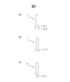
- FIG. 2 is a side view illustrating a conical tool used for chamfering.
- the conical tool 1 includes, for example, a cutting blade portion 11-1 whose conical shape spreads toward the cutting edge and a cutting portion 11-2 whose conical shape narrows toward the cutting edge as shown in FIG. 2 having a cutting portion formed by sticking, a cutting blade portion 11-1 having a conical shape spreading toward the cutting edge as shown in FIG. 2B, as shown in FIG. 2C Some have a cutting portion 11-2 whose conical shape narrows toward the cutting edge.
- Each conical tool 1 depends on whether the opening edge portion of the cross hole to be chamfered is located in the convex arc shape portion or the concave arc shape portion of the workpiece W, the size of the cutting blade portion, or the like. It is properly used.
- FIG. 3 is a cross-sectional view illustrating a conical tool used for chamfering an opening edge of a cross hole located on a convex arc-shaped portion of a workpiece made of a hollow bar.
- the conical tool 1 shown in FIG. 2A when used for chamfering the opening edge 21-1 of the workpiece W, for example, the cutting blade portion 11-2 is moved from the outside of the workpiece W. Chamfering is performed by rotating the conical tool 1 against the opening edge 21-1.
- the conical tool 1 shown in FIG. 2C may be used (not shown). In this case, the cutting portion 11-2 is pressed against the opening edge 21-1 from the outside of the workpiece W. Chamfering is performed by rotating the conical tool 1.
- FIG. 4 is a cross-sectional view (No. 1) for explaining a conical tool used for chamfering of an opening edge portion of a cross hole located on a concave arc-shaped portion of a workpiece made of a hollow bar.
- the conical tool 1 shown in FIG. 2A when used for chamfering the opening edge 21-2 of the work W, for example, the cutting blade 11-1 and the cross hole 2-1 Chamfering is performed by inserting 11-2 and rotating the conical tool 1 by pressing the cutting blade portion 11-1 against the opening edge 21-2 from the inside of the hollow portion of the workpiece W.
- the conical tool 1 shown in FIG. 2B may be used (not shown). In this case, the cutting blade portion 11-1 is inserted into the cross hole 2-1, and the hollow portion of the workpiece W is removed. Chamfering is performed by pressing the cutting blade 11-1 against the opening edge 21-2 from the inside and rotating the conical tool 1.
- FIG. 5 is a diagram (No. 2) for explaining a conical tool used for chamfering of an opening edge portion of a cross hole located on a concave arc-shaped portion of a workpiece made of a hollow bar, (a) It is the longitudinal cross-sectional view seen from the surface orthogonal to the circular arc central axis direction of a workpiece
- the conical tool 1 shown in FIG. 2C is used for chamfering the opening edge 21-2 of the workpiece W, for example, the cutting blade portion 11-2 is provided in the hollow portion of the workpiece W.
- Chamfering is performed by inserting and rotating the conical tool 1 by pressing the cutting blade portion 11-2 against the opening edge portion 21-2 from the inside of the hollow portion of the workpiece W.
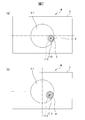
- FIG. 6 is a view for explaining the positional relationship between a workpiece made of a hollow bar in a chamfering process and a cutting blade portion of a conical tool, wherein (a) is a cross hole located on a concave arc-shaped portion of the workpiece. (B) is sectional drawing of the cross hole located on the concave circular arc shape part of a workpiece
- FIG. 6 (a) When chamfering the cross hole 2-1 located on the concave arcuate portion 4 shown in FIGS. 6 (a) and 6 (b) is performed using the conical tool 1 shown in FIG. 6 (c), FIG. As shown in FIG. 6 (a), the points P 0 , P 1 and P 2 that appear to be located on the circle of the cross hole 2-1 from the upper surface are located on the concave arcuate portion 4 of the workpiece W. As shown in FIG. 6B, the height position in the penetrating direction of the cross hole 2-1 decreases as the distance from the arc central axis increases. For example, when performing chamfering the point P 0 as the processing point with a point T 0 of the cutting edge portion 11-2 of the conical tool 1 shown in FIG.
- the height of the cutting edge portion 11-2 If the cutting blade 11-2 is moved in a direction orthogonal to the arc central axis direction while rotating the conical tool without changing the machining point P 0 , the machining point P 0 is caused by the inclination with the curvature of the inner peripheral surface.
- the point T 1 of the cutting blade portion 11-2 is in contact with the point P 1 that is lower than the point P 1 , and the point of the cutting blade portion 11-2 is lower than the point P 2 that is lower than the addition P 1 . Since the point T 2 contacts, the points P 1 and P 2 that are not scheduled to be processed are cut excessively.
- FIG. 7 is a diagram for explaining the principle of the chamfering method according to the present invention.
- the cutting blade is set at a processing point P with respect to the inner peripheral surface side of the workpiece W.
- the portion Q with respect to the convex arcuate shape portion 3 located at a position higher than the machining point P in the rotation of the inclination of the cutting blade portion 11-2 and the arc of the inner peripheral surface. Therefore, the portion Q that is not scheduled to be processed is cut excessively.
- the height of the conical tool 1 and the position of the rotation axis are set so that the cutting portion 11-2 contacts the inner wall of the workpiece W only at the processing point P. Control is performed to sequentially change at least one of them.
- FIG. 7B when the conical tool 1 is moved while being rotated, the position of the rotation axis of the conical tool 1 is cross hole so that the cutting part 11-2 contacts the inner wall of the workpiece W only at the processing point P.
- the change is made sequentially in the direction away from the opening edge of 2-1.
- the height of the conical tool 1 is sequentially increased so that the cutting unit 11-2 contacts the inner wall of the workpiece W only at the processing point P when the conical tool 1 is rotated and moved.
- both the height of the conical tool 1 and the position of the rotating shaft may be sequentially changed.
- the chamfering method based on the conical curve generated when the cutting edge of the conical tool is cut in a virtual plane in contact with the machining point for the cross hole of the conical tool and the shape of the opening edge of the cross hole, The height of the tool and the position of the rotary shaft are controlled, and chamfering is performed so that a surface having the same width is formed at the opening edge of the cross hole.
- the conic curve will be described below.
- FIG. 8 is a diagram for explaining a conical curve generated when a cutting blade portion of a conical tool is cut along a virtual plane.
- a conic curve is a general term for a group of curves obtained as a cross section when a conical surface is cut along an arbitrary plane.
- the conic curve becomes an ellipse.
- the conic curve becomes a hyperbola.
- the conic curve becomes a parabola.
- the conical curve L1 becomes an ellipse as shown in FIG. 8B.
- the conic curve L2 becomes a hyperbola as shown in FIG. 8B.
- FIG. 9 is a diagram (part 1) for explaining chamfering of an opening edge portion of a cross hole located on a convex arc-shaped portion of a workpiece made of a hollow bar, in which (a) is a cross-sectional view. (B) is a top view.
- FIG. 9A when the machining point P of the opening edge 21-1 is chamfered by the cutting blade part 11-2, the virtual plane V in contact with the machining point P is all of the cutting blade part 11. Since the plane intersects with the generatrix and is not parallel to the bottom surface, the conical curve L generated when the cutting blade portion 11-2 is cut on the virtual plane V becomes an ellipse as shown in FIG. 9B.
- the cutting blade portion 11-2 is set to the processing point P.
- chamfering is performed so that a surface having the same width is formed at the opening edge 21-1.
- FIG. 10 is a diagram (part 2) for explaining chamfering of an opening edge portion of a cross hole located on a convex arc-shaped portion of a workpiece made of a hollow bar, in which (a) is a cross-sectional view. (B) is a top view.
- FIG. 10A when the machining point P of the opening edge 21-1 is chamfered by the cutting blade 11-2, the virtual plane V in contact with the machining point P is a cutting blade having a conical shape. Since it is not parallel to the generatrix of the part 11-2, the conic curve L generated when the cutting blade part 11-2 is cut on the virtual plane V becomes a hyperbola as shown in FIG.
- the height of the conical tool 1 and the position of the rotary shaft are controlled so that the conical curve L formed by the hyperbola contacts the inner wall of the cross hole 2-1 at one point, and the cutting blade portion 11-2 is set as the processing point P.
- chamfering is performed so that a surface having the same width is formed at the opening edge 21-1.
- the conic curve L generated when the cutting blade portion is cut at the virtual plane V in contact with the machining point P with respect to the cross hole of the conical tool 1 is determined by the cutting blade portion of the conical tool 1. It is determined by the size of the apex angle of the conical shape, the position on the generatrix of the cutting blade portion of the conical tool 1, the inner and outer diameters of the hollow bar of the workpiece W, and the inner diameter of the cross hole. Therefore, in the present invention, the height of the conical tool and the position of the rotary shaft are set to the size of the apex angle of the conical shape of the cutting edge of the conical tool 1 and the position on the generatrix, the inner diameter and the outer diameter of the hollow bar of the workpiece W. Control is based on the diameter as well as the inner diameter of the cross hole. The height of the conical tool 1 and the position of the rotary shaft are controlled by a control device (not shown) that controls the rotational operation and height of the conical tool 1.
- FIG. 11 is a cross-sectional view for explaining the processing points at the opening edge of the cross hole located on the concave arc-shaped part of the workpiece made of a hollow bar.
- FIG. 12 is a cross-sectional view for explaining processing points at the opening edge of the cross hole located on the convex arc-shaped portion of the workpiece made of a hollow bar.
- the opening edge portion to be chamfered is provided in the concave arc shape portion and the convex arc shape portion of the workpiece has been described. Even an opening edge portion formed can be applied.
- the chamfering method of the present invention can also be applied when the opening edge portion to be chamfered is a long hole or a square hole, or when the cross hole has a tapered shape instead of a cylindrical shape. it can.
- the workpiece to which the chamfering method of the present invention can be applied is not limited to a round member having a cylindrical shape, and may be a round member having a tapered shape on the outer diameter or a square member.
- the chamfering method of the present invention is also applied to chamfering in an inner part of a workpiece such as a cross hole intersecting a center hole along the axial direction of the workpiece or a crossing portion of cross holes. Can do. In this case, chamfering is performed by inserting a conical tool from the center hole or one of the cross holes.
- the chamfering method of the present invention can be executed using the spherical tool instead of the conical tool.
- a machine tool that executes the chamfering method including the above-described processes includes a spindle that grips a workpiece, a tool spindle on which a conical tool is mounted, and a controller that controls rotation of the spindle and the tool spindle.
- the height of the conical tool and the position of the rotary axis are controlled by a control device.
- the present invention can be applied to a machine tool that performs chamfering on an opening edge of a cross hole formed in a workpiece.
Landscapes
- Engineering & Computer Science (AREA)
- Mechanical Engineering (AREA)
- Milling Processes (AREA)
- Milling, Broaching, Filing, Reaming, And Others (AREA)
- Grinding And Polishing Of Tertiary Curved Surfaces And Surfaces With Complex Shapes (AREA)
- Drilling And Boring (AREA)
Abstract
Description
2-1、2-2 クロス穴
3 凸状円弧形状部
4 凹状円弧形状部
11-1、11-2 切削刃部
21-1、21-2、21-3、21-4 開口縁部
W ワーク
Claims (3)
- ワークに形成されたクロス穴の開口縁部の面取加工を、円錐状の切削刃部を有する円錐工具を回転させながら行う面取加工方法であって、
前記円錐工具の前記クロス穴に対する加工点に接する仮想平面で前記切削刃部を切断した際に生じる円錐曲線と、前記クロス穴の開口縁部形状とに基づき、前記円錐工具の高さおよび回転軸の位置のうちの少なくとも1つを制御して、前記クロス穴の開口縁部に同一幅の面が形成されるよう面取加工をすることを特徴とする面取加工方法。 - 前記円錐工具の前記切削刃部の円錐形状の頂角の大きさおよび母線上の位置、前記ワークの中空形状の内径および外径、ならびに前記クロス穴の内径に基づいて、前記円錐工具の高さおよび回転軸の位置のうちの少なくとも1つを制御する請求項1に記載の面取加工方法。
- 前記円錐曲線が、前記クロス穴の内壁に対して1点で接するよう、前記円錐工具の前記クロス穴の貫通方向に対する高さおよび回転軸の位置のうちの少なくとも1つを制御する請求項1または2に記載の面取加工方法。
Priority Applications (5)
| Application Number | Priority Date | Filing Date | Title |
|---|---|---|---|
| EP14792203.3A EP2992997A4 (en) | 2013-04-30 | 2014-04-25 | METHOD OF ABROADING |
| CN201480024307.3A CN105209221B (zh) | 2013-04-30 | 2014-04-25 | 倒角加工方法 |
| US14/779,323 US9956624B2 (en) | 2013-04-30 | 2014-04-25 | Chamfer machining method |
| KR1020157027370A KR102012913B1 (ko) | 2013-04-30 | 2014-04-25 | 면취 가공 방법 |
| JP2015514835A JP6313287B2 (ja) | 2013-04-30 | 2014-04-25 | 面取加工方法 |
Applications Claiming Priority (2)
| Application Number | Priority Date | Filing Date | Title |
|---|---|---|---|
| JP2013095927 | 2013-04-30 | ||
| JP2013-095927 | 2013-04-30 |
Publications (1)
| Publication Number | Publication Date |
|---|---|
| WO2014178355A1 true WO2014178355A1 (ja) | 2014-11-06 |
Family
ID=51843483
Family Applications (1)
| Application Number | Title | Priority Date | Filing Date |
|---|---|---|---|
| PCT/JP2014/061777 Ceased WO2014178355A1 (ja) | 2013-04-30 | 2014-04-25 | 面取加工方法 |
Country Status (7)
| Country | Link |
|---|---|
| US (1) | US9956624B2 (ja) |
| EP (1) | EP2992997A4 (ja) |
| JP (2) | JP6313287B2 (ja) |
| KR (1) | KR102012913B1 (ja) |
| CN (1) | CN105209221B (ja) |
| TW (1) | TWI620628B (ja) |
| WO (1) | WO2014178355A1 (ja) |
Cited By (12)
| Publication number | Priority date | Publication date | Assignee | Title |
|---|---|---|---|---|
| JP2016112634A (ja) * | 2014-12-12 | 2016-06-23 | 株式会社 東陽 | 切削工具及びこの切削工具を備えた切削装置 |
| JP2017170565A (ja) * | 2016-03-23 | 2017-09-28 | 若林工業株式会社 | 長孔のバリ取り装置及びこれを用いたバリ取り方法 |
| CN108380980A (zh) * | 2018-05-09 | 2018-08-10 | 浙江柏思达齿轮股份有限公司 | 锥齿轮的内孔端口倒角装置及倒角方法 |
| JP2018134706A (ja) * | 2017-02-22 | 2018-08-30 | ジヤトコ株式会社 | バリ取り方法、バリ取り装置の制御装置、バリ取り装置用の制御プログラム |
| US20220203462A1 (en) * | 2019-04-26 | 2022-06-30 | Makino Milling Machine Co., Ltd. | Milling tool and workpiece machining method |
| JP2022531819A (ja) * | 2019-02-11 | 2022-07-12 | メキシケム フロー エセ・ア・デ・セ・ヴェ | 組成物 |
| JP7201884B1 (ja) * | 2022-04-28 | 2023-01-10 | ファナック株式会社 | 演算装置、工作機械、工作機械の制御装置、および演算プログラム |
| JP7201883B1 (ja) * | 2022-04-28 | 2023-01-10 | ファナック株式会社 | 演算装置、工作機械、工作機械の制御装置、および演算プログラム |
| JPWO2023210002A1 (ja) * | 2022-04-28 | 2023-11-02 | ||
| WO2023209999A1 (ja) * | 2022-04-28 | 2023-11-02 | ファナック株式会社 | 演算装置、工作機械、工作機械の制御装置、および演算プログラム |
| TWI844727B (zh) * | 2019-11-06 | 2024-06-11 | 日商銳必克科技有限公司 | 倒角刀具及工件的倒角方法 |
| EP4678317A1 (en) | 2024-07-08 | 2026-01-14 | Star Micronics Co., Ltd. | Machine tool and method of determining control position thereof |
Families Citing this family (12)
| Publication number | Priority date | Publication date | Assignee | Title |
|---|---|---|---|---|
| CN106312765A (zh) * | 2016-09-26 | 2017-01-11 | 中车株洲电机有限公司 | 一种轴上小孔倒角加工装置和方法 |
| CN108317122B (zh) * | 2017-01-16 | 2023-09-15 | 浙江师范大学 | 一种用于循环球液压转向器的双孔式无压差机构 |
| CN107914046A (zh) * | 2017-11-15 | 2018-04-17 | 珠海市魅族科技有限公司 | 倒角的加工方法和终端 |
| JP6767417B2 (ja) | 2018-03-29 | 2020-10-14 | 平田機工株式会社 | 加工システム及び加工方法 |
| CN109648257B (zh) * | 2018-11-30 | 2020-12-25 | 中国航空工业集团公司金城南京机电液压工程研究中心 | 一种角向组合装置贯通孔的加工方法 |
| CN109719353A (zh) * | 2019-01-02 | 2019-05-07 | 桂林福达曲轴有限公司 | 一种用于曲轴相交油孔去除毛刺的刀具及其使用方法 |
| US12202089B2 (en) * | 2019-09-17 | 2025-01-21 | Sumitomo Electric Sintered Alloy, Ltd. | Metal member, processing system, and method for manufacturing metal member |
| CN112475824B (zh) * | 2020-11-13 | 2021-11-23 | 本田金属技术(佛山)有限公司 | 加工台阶孔倒角的加工方法 |
| CN112848405B (zh) * | 2021-02-07 | 2023-07-04 | 江阴市科诚技术有限公司 | 一种风电叶片主梁用拉挤板材后处理生产线倒角方法 |
| CN112958818A (zh) * | 2021-03-17 | 2021-06-15 | 中国航发动力股份有限公司 | 一种孔口倒圆的加工方法 |
| CN113909530A (zh) * | 2021-11-11 | 2022-01-11 | 贵州航天电子科技有限公司 | 一种去除波导管内壁孔毛刺工具 |
| CN115570464A (zh) * | 2022-06-29 | 2023-01-06 | 新乡辉簧弹簧有限公司 | 一种自动对电机机壳导线孔进行倒角的设备 |
Citations (6)
| Publication number | Priority date | Publication date | Assignee | Title |
|---|---|---|---|---|
| JPH03256659A (ja) * | 1990-03-05 | 1991-11-15 | Suzuki Motor Corp | 2サイクルエンジン用シリンダポートの面取り方法 |
| JP2004223638A (ja) | 2003-01-21 | 2004-08-12 | Farukomu:Kk | バリ取り方法及びバリ取り装置 |
| US20070122245A1 (en) * | 2004-08-20 | 2007-05-31 | Osamu Yanagimoto | Chamfering tool |
| JP2007265237A (ja) * | 2006-03-29 | 2007-10-11 | Farukomu:Kk | ワーク補正装置及びワーク加工装置 |
| JP2010149271A (ja) | 2008-11-26 | 2010-07-08 | Hitachi Ltd | 角部加工工具 |
| JP5150194B2 (ja) | 2007-10-15 | 2013-02-20 | 株式会社ジーベックテクノロジー | 研磨工具および加工方法 |
Family Cites Families (23)
| Publication number | Priority date | Publication date | Assignee | Title |
|---|---|---|---|---|
| US2773402A (en) * | 1954-11-12 | 1956-12-11 | Falcon Tool Company | Means for form cutting structure at the peripheries of round holes in curved elements |
| US3545311A (en) * | 1968-08-12 | 1970-12-08 | Thiokol Chemical Corp | Deburring tool |
| JPS5150194A (ja) | 1974-10-28 | 1976-05-01 | Koji Kato | Senpaku |
| DE3209439C2 (de) | 1981-12-23 | 1987-03-19 | Klöckner-Werke AG, 4100 Duisburg | Vorrichtung zum Schneiden eines Rohres mittels einer automatisch gesteuerten Rohrbrennschneidmaschine |
| DE8225992U1 (de) * | 1982-09-15 | 1982-12-23 | Kadia Diamant Maschinen- und Werkzeugfabrik O. Kopp GmbH & Co, 7440 Nürtingen | Bohr- und entgratkopf und darin einspannbares bohr- und entgratwerkzeug |
| DE8408226U1 (de) * | 1984-03-17 | 1986-01-23 | Maschinenfabrik Alfing Keßler GmbH, 7080 Aalen | Werkzeug zum Bearbeiten der Übergänge von Bohrungen |
| DE3505084A1 (de) | 1985-02-14 | 1986-08-14 | Heinrich Balgach Heule | Entgratwerkzeug zur entgratung von bohrungsraendern von gewoelbten oder schraegen werkstuecksoberflaechen |
| JPS6367015A (ja) | 1986-09-09 | 1988-03-25 | Sanyuu Kogyo Kk | ソリツドステ−トリレ− |
| JPH0333379Y2 (ja) | 1986-10-23 | 1991-07-16 | ||
| DE3727103A1 (de) * | 1987-08-14 | 1989-02-23 | Index Werke Kg Hahn & Tessky | Werkzeug zum entgraten des uebergangs zwischen zwei bohrungen |
| JPH05123915A (ja) * | 1991-11-01 | 1993-05-21 | Jidosha Kiki Co Ltd | 回転工具 |
| US5167477A (en) * | 1992-02-10 | 1992-12-01 | Rickard Falkensson | Chamfering device and tool holder therefor |
| US5173013A (en) * | 1992-02-28 | 1992-12-22 | Eaton Corporation | Combined hole cutting and chamfering tool |
| JPH09253914A (ja) * | 1996-03-22 | 1997-09-30 | Iriso Seimitsu:Kk | 切削工具 |
| JPH11129116A (ja) * | 1997-10-28 | 1999-05-18 | Honda Motor Co Ltd | リーマーおよびその使用方法 |
| JPH11320231A (ja) * | 1998-05-20 | 1999-11-24 | Honda Motor Co Ltd | 面取り加工機 |
| DE10119645A1 (de) * | 2001-04-20 | 2002-05-29 | Andre Woitschach Gmbh | Rotierendes Bearbeitungswekzeug und Verfahren zum Aufbohren, Senken oder Anfasen |
| JP2003285202A (ja) * | 2002-03-28 | 2003-10-07 | Nakamura Tome Precision Ind Co Ltd | 円筒ワークの横孔の面取加工方法 |
| JP2007015028A (ja) * | 2005-07-05 | 2007-01-25 | Farukomu:Kk | ワーク処理装置 |
| ITBO20050752A1 (it) * | 2005-12-07 | 2007-06-08 | Jobs Spa | Portautensili per fresatrici, macchina fresatrice e procedimento di fresatura |
| US20080005907A1 (en) * | 2006-06-28 | 2008-01-10 | Douglas Scheffer | Ductile iron beveling tool |
| CN201275649Y (zh) * | 2008-08-12 | 2009-07-22 | 广西玉柴机器股份有限公司 | 孔口毛刺去除工具 |
| US8690498B2 (en) * | 2010-04-19 | 2014-04-08 | Yamazaki Mazak Corporation | Cutting machining method and cutting machining apparatus |
-
2014
- 2014-04-25 KR KR1020157027370A patent/KR102012913B1/ko active Active
- 2014-04-25 CN CN201480024307.3A patent/CN105209221B/zh active Active
- 2014-04-25 WO PCT/JP2014/061777 patent/WO2014178355A1/ja not_active Ceased
- 2014-04-25 US US14/779,323 patent/US9956624B2/en active Active
- 2014-04-25 EP EP14792203.3A patent/EP2992997A4/en active Pending
- 2014-04-25 JP JP2015514835A patent/JP6313287B2/ja active Active
- 2014-04-29 TW TW103115333A patent/TWI620628B/zh active
-
2018
- 2018-03-22 JP JP2018055159A patent/JP6494830B2/ja active Active
Patent Citations (6)
| Publication number | Priority date | Publication date | Assignee | Title |
|---|---|---|---|---|
| JPH03256659A (ja) * | 1990-03-05 | 1991-11-15 | Suzuki Motor Corp | 2サイクルエンジン用シリンダポートの面取り方法 |
| JP2004223638A (ja) | 2003-01-21 | 2004-08-12 | Farukomu:Kk | バリ取り方法及びバリ取り装置 |
| US20070122245A1 (en) * | 2004-08-20 | 2007-05-31 | Osamu Yanagimoto | Chamfering tool |
| JP2007265237A (ja) * | 2006-03-29 | 2007-10-11 | Farukomu:Kk | ワーク補正装置及びワーク加工装置 |
| JP5150194B2 (ja) | 2007-10-15 | 2013-02-20 | 株式会社ジーベックテクノロジー | 研磨工具および加工方法 |
| JP2010149271A (ja) | 2008-11-26 | 2010-07-08 | Hitachi Ltd | 角部加工工具 |
Non-Patent Citations (1)
| Title |
|---|
| See also references of EP2992997A4 |
Cited By (20)
| Publication number | Priority date | Publication date | Assignee | Title |
|---|---|---|---|---|
| JP2016112634A (ja) * | 2014-12-12 | 2016-06-23 | 株式会社 東陽 | 切削工具及びこの切削工具を備えた切削装置 |
| JP2017170565A (ja) * | 2016-03-23 | 2017-09-28 | 若林工業株式会社 | 長孔のバリ取り装置及びこれを用いたバリ取り方法 |
| JP2018134706A (ja) * | 2017-02-22 | 2018-08-30 | ジヤトコ株式会社 | バリ取り方法、バリ取り装置の制御装置、バリ取り装置用の制御プログラム |
| CN108380980A (zh) * | 2018-05-09 | 2018-08-10 | 浙江柏思达齿轮股份有限公司 | 锥齿轮的内孔端口倒角装置及倒角方法 |
| JP2022531819A (ja) * | 2019-02-11 | 2022-07-12 | メキシケム フロー エセ・ア・デ・セ・ヴェ | 組成物 |
| US12214430B2 (en) * | 2019-04-26 | 2025-02-04 | Makino Milling Machine Co., Ltd. | Milling tool and workpiece machining method |
| US20220203462A1 (en) * | 2019-04-26 | 2022-06-30 | Makino Milling Machine Co., Ltd. | Milling tool and workpiece machining method |
| TWI844727B (zh) * | 2019-11-06 | 2024-06-11 | 日商銳必克科技有限公司 | 倒角刀具及工件的倒角方法 |
| WO2023210003A1 (ja) * | 2022-04-28 | 2023-11-02 | ファナック株式会社 | 演算装置、工作機械、工作機械の制御装置、および演算プログラム |
| JP7201884B1 (ja) * | 2022-04-28 | 2023-01-10 | ファナック株式会社 | 演算装置、工作機械、工作機械の制御装置、および演算プログラム |
| WO2023210005A1 (ja) * | 2022-04-28 | 2023-11-02 | ファナック株式会社 | 演算装置、工作機械、工作機械の制御装置、および演算プログラム |
| WO2023209999A1 (ja) * | 2022-04-28 | 2023-11-02 | ファナック株式会社 | 演算装置、工作機械、工作機械の制御装置、および演算プログラム |
| WO2023210002A1 (ja) * | 2022-04-28 | 2023-11-02 | ファナック株式会社 | 演算装置、工作機械、工作機械の制御装置、および演算プログラム |
| JPWO2023209999A1 (ja) * | 2022-04-28 | 2023-11-02 | ||
| JPWO2023210002A1 (ja) * | 2022-04-28 | 2023-11-02 | ||
| JP7201883B1 (ja) * | 2022-04-28 | 2023-01-10 | ファナック株式会社 | 演算装置、工作機械、工作機械の制御装置、および演算プログラム |
| JP7747883B2 (ja) | 2022-04-28 | 2025-10-01 | ファナック株式会社 | 演算装置、工作機械、工作機械の制御装置、および演算プログラム |
| JP7747884B2 (ja) | 2022-04-28 | 2025-10-01 | ファナック株式会社 | 演算装置、工作機械、工作機械の制御装置、および演算プログラム |
| EP4678317A1 (en) | 2024-07-08 | 2026-01-14 | Star Micronics Co., Ltd. | Machine tool and method of determining control position thereof |
| KR20260008017A (ko) | 2024-07-08 | 2026-01-15 | 스타 마이크로닉스 컴퍼니 리미티드 | 공작 기계, 및 그 제어 위치 결정 방법 |
Also Published As
| Publication number | Publication date |
|---|---|
| TWI620628B (zh) | 2018-04-11 |
| US9956624B2 (en) | 2018-05-01 |
| JPWO2014178355A1 (ja) | 2017-02-23 |
| CN105209221B (zh) | 2017-08-08 |
| KR102012913B1 (ko) | 2019-08-22 |
| TW201505801A (zh) | 2015-02-16 |
| CN105209221A (zh) | 2015-12-30 |
| EP2992997A1 (en) | 2016-03-09 |
| JP6313287B2 (ja) | 2018-04-18 |
| JP2018134731A (ja) | 2018-08-30 |
| US20160052070A1 (en) | 2016-02-25 |
| JP6494830B2 (ja) | 2019-04-03 |
| EP2992997A4 (en) | 2016-12-21 |
| KR20160002740A (ko) | 2016-01-08 |
Similar Documents
| Publication | Publication Date | Title |
|---|---|---|
| JP6494830B2 (ja) | 制御装置及び工作機械 | |
| US9561535B2 (en) | Method for milling a cutout in a workpiece, and workpiece having a cutout | |
| JP2016112634A (ja) | 切削工具及びこの切削工具を備えた切削装置 | |
| JP2012166339A (ja) | バリ取り工具 | |
| CN105269053A (zh) | 去毛刺与倒圆角装置 | |
| CN205587692U (zh) | 机床 | |
| JP2015517921A (ja) | 円形材の面削り作業時に最適の作業条件を提供する面取機及び面削り方法 | |
| US11077501B2 (en) | Method of machining a rotationally symmetric surface of a workpiece and turning apparatus | |
| KR20090075599A (ko) | 로터리 커터 | |
| JP6379623B2 (ja) | 切削装置および切削方法 | |
| JP2013107177A (ja) | ボーリング加工方法及びボーリング加工装置 | |
| JP2018199179A (ja) | 切削工具及びこの切削工具を備えた切削装置 | |
| JP4946967B2 (ja) | 面取り工具 | |
| JPH08252712A (ja) | 円筒体周面にあけた穴の開先加工具及び開先加工法 | |
| CN105004623B (zh) | 一种新型获取钻削切屑根部的工件 | |
| JP2012096354A (ja) | シート面加工方法 | |
| CN115319136B (zh) | 深沟球保持架球型兜孔加工方法 | |
| JP4876540B2 (ja) | スローアウェイチップ及びその研削方法 | |
| JP2003326410A (ja) | センタドリル | |
| JPH0839322A (ja) | 貫通穴の開口縁加工装置 | |
| JP2017148883A (ja) | スカイビング加工装置及びその加工方法 | |
| CN205927708U (zh) | 微调式内径车花刀 | |
| TWM538421U (zh) | 車刀及車削單元 | |
| CN203900570U (zh) | 刃尖在圆周的四刃钻头 | |
| JP2021062377A (ja) | チップドレッサー |
Legal Events
| Date | Code | Title | Description |
|---|---|---|---|
| 121 | Ep: the epo has been informed by wipo that ep was designated in this application |
Ref document number: 14792203 Country of ref document: EP Kind code of ref document: A1 |
|
| ENP | Entry into the national phase |
Ref document number: 2015514835 Country of ref document: JP Kind code of ref document: A |
|
| WWE | Wipo information: entry into national phase |
Ref document number: 2014792203 Country of ref document: EP |
|
| WWE | Wipo information: entry into national phase |
Ref document number: 14779323 Country of ref document: US |
|
| ENP | Entry into the national phase |
Ref document number: 20157027370 Country of ref document: KR Kind code of ref document: A |
|
| NENP | Non-entry into the national phase |
Ref country code: DE |