WO2014156357A1 - 粉体塗工装置、およびそれを用いたリチウムイオン電池用電極の製造方法 - Google Patents
粉体塗工装置、およびそれを用いたリチウムイオン電池用電極の製造方法 Download PDFInfo
- Publication number
- WO2014156357A1 WO2014156357A1 PCT/JP2014/053429 JP2014053429W WO2014156357A1 WO 2014156357 A1 WO2014156357 A1 WO 2014156357A1 JP 2014053429 W JP2014053429 W JP 2014053429W WO 2014156357 A1 WO2014156357 A1 WO 2014156357A1
- Authority
- WO
- WIPO (PCT)
- Prior art keywords
- powder
- squeegee
- roller
- outer peripheral
- press
- Prior art date
- Legal status (The legal status is an assumption and is not a legal conclusion. Google has not performed a legal analysis and makes no representation as to the accuracy of the status listed.)
- Ceased
Links
Images


Classifications
-
- H—ELECTRICITY
- H01—ELECTRIC ELEMENTS
- H01M—PROCESSES OR MEANS, e.g. BATTERIES, FOR THE DIRECT CONVERSION OF CHEMICAL ENERGY INTO ELECTRICAL ENERGY
- H01M4/00—Electrodes
- H01M4/02—Electrodes composed of, or comprising, active material
- H01M4/04—Processes of manufacture in general
- H01M4/043—Processes of manufacture in general involving compressing or compaction
- H01M4/0435—Rolling or calendering
-
- H—ELECTRICITY
- H01—ELECTRIC ELEMENTS
- H01M—PROCESSES OR MEANS, e.g. BATTERIES, FOR THE DIRECT CONVERSION OF CHEMICAL ENERGY INTO ELECTRICAL ENERGY
- H01M10/00—Secondary cells; Manufacture thereof
- H01M10/05—Accumulators with non-aqueous electrolyte
- H01M10/052—Li-accumulators
- H01M10/0525—Rocking-chair batteries, i.e. batteries with lithium insertion or intercalation in both electrodes; Lithium-ion batteries
-
- H—ELECTRICITY
- H01—ELECTRIC ELEMENTS
- H01M—PROCESSES OR MEANS, e.g. BATTERIES, FOR THE DIRECT CONVERSION OF CHEMICAL ENERGY INTO ELECTRICAL ENERGY
- H01M4/00—Electrodes
- H01M4/02—Electrodes composed of, or comprising, active material
- H01M4/04—Processes of manufacture in general
- H01M4/0402—Methods of deposition of the material
- H01M4/0404—Methods of deposition of the material by coating on electrode collectors
-
- H—ELECTRICITY
- H01—ELECTRIC ELEMENTS
- H01M—PROCESSES OR MEANS, e.g. BATTERIES, FOR THE DIRECT CONVERSION OF CHEMICAL ENERGY INTO ELECTRICAL ENERGY
- H01M4/00—Electrodes
- H01M4/02—Electrodes composed of, or comprising, active material
- H01M4/04—Processes of manufacture in general
- H01M4/0402—Methods of deposition of the material
- H01M4/0409—Methods of deposition of the material by a doctor blade method, slip-casting or roller coating
-
- H—ELECTRICITY
- H01—ELECTRIC ELEMENTS
- H01M—PROCESSES OR MEANS, e.g. BATTERIES, FOR THE DIRECT CONVERSION OF CHEMICAL ENERGY INTO ELECTRICAL ENERGY
- H01M4/00—Electrodes
- H01M4/02—Electrodes composed of, or comprising, active material
- H01M4/04—Processes of manufacture in general
- H01M4/043—Processes of manufacture in general involving compressing or compaction
-
- H—ELECTRICITY
- H01—ELECTRIC ELEMENTS
- H01M—PROCESSES OR MEANS, e.g. BATTERIES, FOR THE DIRECT CONVERSION OF CHEMICAL ENERGY INTO ELECTRICAL ENERGY
- H01M4/00—Electrodes
- H01M4/02—Electrodes composed of, or comprising, active material
- H01M4/13—Electrodes for accumulators with non-aqueous electrolyte, e.g. for lithium-accumulators; Processes of manufacture thereof
- H01M4/139—Processes of manufacture
-
- B—PERFORMING OPERATIONS; TRANSPORTING
- B05—SPRAYING OR ATOMISING IN GENERAL; APPLYING FLUENT MATERIALS TO SURFACES, IN GENERAL
- B05C—APPARATUS FOR APPLYING FLUENT MATERIALS TO SURFACES, IN GENERAL
- B05C1/00—Apparatus in which liquid or other fluent material is applied to the surface of the work by contact with a member carrying the liquid or other fluent material, e.g. a porous member loaded with a liquid to be applied as a coating
- B05C1/04—Apparatus in which liquid or other fluent material is applied to the surface of the work by contact with a member carrying the liquid or other fluent material, e.g. a porous member loaded with a liquid to be applied as a coating for applying liquid or other fluent material to work of indefinite length
- B05C1/08—Apparatus in which liquid or other fluent material is applied to the surface of the work by contact with a member carrying the liquid or other fluent material, e.g. a porous member loaded with a liquid to be applied as a coating for applying liquid or other fluent material to work of indefinite length using a roller or other rotating member which contacts the work along a generating line
- B05C1/0813—Apparatus in which liquid or other fluent material is applied to the surface of the work by contact with a member carrying the liquid or other fluent material, e.g. a porous member loaded with a liquid to be applied as a coating for applying liquid or other fluent material to work of indefinite length using a roller or other rotating member which contacts the work along a generating line characterised by means for supplying liquid or other fluent material to the roller
-
- B—PERFORMING OPERATIONS; TRANSPORTING
- B05—SPRAYING OR ATOMISING IN GENERAL; APPLYING FLUENT MATERIALS TO SURFACES, IN GENERAL
- B05C—APPARATUS FOR APPLYING FLUENT MATERIALS TO SURFACES, IN GENERAL
- B05C9/00—Apparatus or plant for applying liquid or other fluent material to surfaces by means not covered by any preceding group, or in which the means of applying the liquid or other fluent material is not important
- B05C9/04—Apparatus or plant for applying liquid or other fluent material to surfaces by means not covered by any preceding group, or in which the means of applying the liquid or other fluent material is not important for applying liquid or other fluent material to opposite sides of the work
-
- H—ELECTRICITY
- H01—ELECTRIC ELEMENTS
- H01M—PROCESSES OR MEANS, e.g. BATTERIES, FOR THE DIRECT CONVERSION OF CHEMICAL ENERGY INTO ELECTRICAL ENERGY
- H01M10/00—Secondary cells; Manufacture thereof
- H01M10/05—Accumulators with non-aqueous electrolyte
- H01M10/052—Li-accumulators
-
- Y—GENERAL TAGGING OF NEW TECHNOLOGICAL DEVELOPMENTS; GENERAL TAGGING OF CROSS-SECTIONAL TECHNOLOGIES SPANNING OVER SEVERAL SECTIONS OF THE IPC; TECHNICAL SUBJECTS COVERED BY FORMER USPC CROSS-REFERENCE ART COLLECTIONS [XRACs] AND DIGESTS
- Y02—TECHNOLOGIES OR APPLICATIONS FOR MITIGATION OR ADAPTATION AGAINST CLIMATE CHANGE
- Y02E—REDUCTION OF GREENHOUSE GAS [GHG] EMISSIONS, RELATED TO ENERGY GENERATION, TRANSMISSION OR DISTRIBUTION
- Y02E60/00—Enabling technologies; Technologies with a potential or indirect contribution to GHG emissions mitigation
- Y02E60/10—Energy storage using batteries
Definitions
- the present invention relates to a powder coating apparatus and a method for producing an electrode for a lithium ion battery using the same.
- Patent Document 1 discloses a technique for applying a composite material (powder) containing an active material on the surface of a current collector (web) that is a long metal foil.
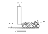
- the powder thickness is uniformly adjusted by supplying the powder onto the surface of the web and then leveling the powder with a blade-shaped squeegee (Patent Document). 1 (see paragraph [0047]).
- An object of the present invention is to provide a technique capable of uniformly leveling the powder supplied on the surface of the supplied member.
- the powder coating apparatus supplies a supply member having a continuous surface to drive the surface so that the surface moves in a predetermined direction, and supplies the powder onto the surface of the supply member.
- the powder supply means is arranged so as to form a predetermined gap between the surface of the supplied member and the powder supplied by the powder supply means onto the surface of the supplied member is leveled.
- a powder coating apparatus comprising: a squeegee that adjusts the thickness of the powder by pressing; and a press unit that compresses the powder that has been averaged by the squeegee. It is formed in a cylindrical shape having an axis that is parallel to the surface and orthogonal to the direction of movement of the surface of the supplied member.
- the squeegee moves in a direction opposite to the moving direction of the surface of the supplied member at a portion of the outer peripheral surface of the squeegee facing the surface of the supplied member. It is preferable to be driven to rotate.
- the squeegee vibrates so that the shortest distance between the outer peripheral surface of the squeegee and the surface of the supplied member is maintained.
- the method for producing an electrode for a lithium ion battery according to the present invention uses the powder coating apparatus described above to form a compressed powder layer made of the powder containing an active material and at least one of a current collector made of a metal foil. Forming on the surface of the substrate.
- the powder supplied on the surface of the member to be supplied can be uniformly leveled.
- the figure which shows the powder coating apparatus which concerns on this invention The figure which shows a mode that powder is leveled by the squeegee roller. The figure which shows a mode that powder is leveled by the squeegee roller. The figure which shows the manufacturing process of the electrode for lithium ion batteries which concerns on this invention. The figure which shows a mode that powder retains in the conventional squeegee.
- the powder coating apparatus 1 is an apparatus that coats the powder P on the surface of the web W while transporting the web W by a predetermined transport device (not shown). Specifically, the powder coating apparatus 1 continuously feeds the powder P onto both sides of the web W while transporting the web W by the transport device, and continuously compresses the powder P.
- This is an apparatus for forming the compressed powder layers L and L on both surfaces of the web W.
- the said conveying apparatus is comprised so that the web W wound by roll shape may be drawn
- the web W is a long thin plate.
- the web W is a current collector made of a metal foil.
- the powder P is a powdery substance.
- the powder P is a particle group including an active material.
- the compressed powder layer L is a layer formed by compressing the powder P.
- the powder coating apparatus 1 includes press rollers 10, 10, hoppers 20, 20, and squeegee rollers 30, 30.
- One press roller 10, hopper 20, and squeegee roller 30 are provided. (Pressing roller 10, hopper 20 and squeegee roller 30 located on the right side of the web W in FIG. 1) and the other pressing roller 10, hopper 20 and squeegee roller 30 (press located on the left side of the web W in FIG. 1)
- the roller 10, the hopper 20, and the squeegee roller 30) are arranged so as to be line-symmetric.
- the vertical direction in FIG. 1 matches the vertical direction
- the horizontal direction in FIG. 1 matches the horizontal direction.
- the one press roller 10, the hopper 20 and the squeegee roller 30 and the other press roller 10, the hopper 20 and the squeegee roller 30 are configured in substantially the same manner. Only the roller 10, the hopper 20, and the squeegee roller 30 will be described.
- the press rollers 10 and 10 are each formed in a cylindrical shape, and are provided horizontally so that their axial centers are parallel to each other.
- the press rollers 10 and 10 are provided at a predetermined interval from each other so as to sandwich the web W conveyed downward in the vertical direction.
- the press rollers 10 and 10 have an outer peripheral surface of one press roller 10 facing one surface of the web W and an outer peripheral surface of the other press roller 10 facing the other surface of the web W. It is provided to do.
- the press rollers 10 and 10 are rotationally driven in opposite directions by a predetermined driving device (not shown) (see arrows on the press rollers 10 and 10 in FIG. 1).
- the hopper 20 is an embodiment of the powder supply means according to the present invention.
- the hopper 20 is configured to store the powder P therein and to supply the powder P onto the outer peripheral surface of the press roller 10.
- the hopper 20 is arranged on the upstream side in the moving direction of the powder P from the position where the outer peripheral surfaces of the press rollers 10 and 10 are closest to each other (hereinafter referred to as “press position”). Therefore, the powder P supplied from the hopper 20 onto the outer peripheral surface of the press roller 10 reaches the press position as the press roller 10 rotates.
- the squeegee roller 30 is a squeegee for leveling the powder P supplied from the hopper 20 onto the outer peripheral surface of the press roller 10.
- the squeegee roller 30 is formed in a cylindrical shape having an outer diameter smaller than that of the press roller 10, and is provided in the vicinity of the press roller 10 so that its axis is parallel to the axis of the press roller 10. That is, the squeegee roller 30 has a cylindrical shape having an axis that is parallel to the outer peripheral surface of the press roller 10 and orthogonal to the moving direction of the outer peripheral surface of the press roller 10 (the rotation direction of the press roller 10). Is formed.
- the squeegee roller 30 is downstream of the hopper 20 in the movement direction of the powder P so as to form a predetermined gap between the squeegee roller 10 and in the movement direction of the powder P from the press position. Arranged upstream.
- the squeegee rollers 30 and 30 are rotationally driven by a predetermined driving device (not shown) in the same direction as the rotation direction of the press roller 10 located in the vicinity thereof (see arrows on the squeegee rollers 30 and 30 in FIG. 1). ).
- a predetermined driving device not shown
- one squeegee roller 30 rotates in the same direction as the rotation direction of one press roller 10
- the other squeegee roller 30 rotates in the same direction as the rotation direction of the other press roller 10.
- the squeegee roller 30 rotates so that a portion of the outer peripheral surface thereof facing the outer peripheral surface of the press roller 10 moves in the direction opposite to the moving direction of the outer peripheral surface of the press roller 10.
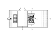
- width adjusting plates 31 and 31 are provided so that the width of the powder P (the vertical dimension in FIG. 2) is constant.
- the width adjusting plates 31 and 31 are provided along the moving direction of the powder P, and are arranged so as to sandwich the powder P along the axial direction of the press roller 10 and the squeegee roller 30.
- the width adjusting plates 31 and 31 have a shape that does not contact the press roller 10 and the squeegee roller 30.
- the width adjustment plates 31 and 31 are fixed to the hopper 20 (see FIG. 1), for example.
- the powder P supplied from one hopper 20 onto the outer peripheral surface of one press roller 10 is pressed as the one press roller 10 rotates.
- the powder P that is leveled by one squeegee roller 30 and supplied from the other hopper 20 onto the outer peripheral surface of the other press roller 10 is rotated by the other press roller 10.
- the other squeegee roller 30 levels out until reaching the press position.
- the powder P supplied onto the outer peripheral surface of one press roller 10 and the powder P supplied onto the outer peripheral surface of the other press roller 10 Pressurized on the surface.
- the compressed powder layers L and L are formed on both surfaces of the web W.
- an adhesive for adhering the powder P is applied to both sides of the web W until the web W reaches the press position.
- the means for applying the adhesive on both surfaces of the web W is not limited, and for example, a gravure coater can be applied.
- the adhesive preferably contains a conductive material.
- the squeegee roller 30 uniformly adjusts the thickness (vertical dimension in FIG. 3) of the powder P by leveling the powder P supplied on the outer peripheral surface of the press roller 10. . That is, since a predetermined gap is formed between the squeegee roller 30 and the press roller 10, the powder P supplied on the outer peripheral surface of the press roller 10 passes through the gap, whereby the powder P Is the shortest distance d between the outer peripheral surface of the squeegee roller 30 and the outer peripheral surface of the press roller 10.
- the squeegee roller 30 is configured to be movable with respect to the press roller 10 so that the distance d can be changed.
- the squeegee roller 30 is formed in a cylindrical shape. Therefore, when the powder P moves toward the gap between the squeegee roller 30 and the press roller 10, a reaction force directed toward the radially outer side of the squeegee roller 30 acts on the powder P that has contacted the outer peripheral surface of the squeegee roller 30. That is, a force directed toward the outer peripheral surface of the press roller 10 acts on the powder P positioned between the squeegee roller 30 and the press roller 10. Further, when the powder P moves toward the gap between the squeegee roller 30 and the press roller 10, the angle formed by the outer peripheral surface of the squeegee roller 30 and the outer peripheral surface of the press roller 10 gradually decreases.
- the direction of the reaction force acting on the powder P in contact with the outer peripheral surface of the squeegee roller 30 gradually changes.
- the powder P can be prevented from staying on the outer peripheral surface of the squeegee roller 30, and the powder P can be satisfactorily passed through the gap between the squeegee roller 30 and the press roller 10. Therefore, it is possible to prevent the thickness of the powder P that has passed through the squeegee roller 30 from becoming non-uniform, and the thickness of the compressed powder layer L can be made uniform.
- the squeegee roller 30 is rotationally driven in the same direction as the rotation direction of the press roller 10.
- the squeegee roller 30 is rotationally driven so that a force in the direction opposite to the moving direction of the powder P acts on the powder P.
- the rotational speed of the squeegee roller 30 is preferably set to about 50% of the rotational speed of the press roller 10. It is also possible to adopt a configuration in which the squeegee roller 30 is not driven to rotate.
- the squeegee roller 30 is preferably vibrated. By vibrating the squeegee roller 30, it is possible to further suppress the powder P from staying on the outer peripheral surface of the squeegee roller 30.
- the direction in which the squeegee roller 30 is vibrated is set such that the shortest distance d between the outer peripheral surface of the squeegee roller 30 and the outer peripheral surface of the press roller 10 is maintained. Specifically, the squeegee roller 30 is vibrated in a direction perpendicular to the direction in which the axis of the squeegee roller 30 approaches and separates from the axis of the press roller 10.
- the direction in which the squeegee roller 30 is vibrated is linear or curved (in the present embodiment, an arc along the outer peripheral surface of the press roller 10).
- the squeegee roller 30 may be vibrated in the axial direction of the squeegee roller 30 or the moving direction of the powder P.
- the vibration of the squeegee roller 30 is set to such an extent that the thickness of the powder P that has passed through the squeegee roller 30 does not become nonuniform (for example, frequency: 700 Hz, amplitude: 5 ⁇ m).
- the powder coating apparatus 1 which concerns on this embodiment is comprised so that the compressed powder layer L * L may be formed on both surfaces of the web W, it is compressed powder on the at least one surface of the web W. What is necessary is just to be comprised so that the layer L may be formed. That is, the powder coating apparatus 1 can be configured to form the compressed powder layer L only on one surface of the web W. In such a case, one hopper 20 and squeegee roller 30 or the other hopper 20 and squeegee roller 30 may not be provided.
- the press roller 10 functions as a supplied member according to the present invention, and the outer peripheral surface of the press roller 10 corresponds to a continuous surface of the supplied member according to the present invention.
- a pair of press rollers 10 and 10 function as a press means according to the present invention.
- the driving device for rotationally driving the press rollers 10, 10 functions as driving means according to the present invention.
- the transport device for transporting the web W functions as a driving unit according to the present invention.
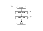
- an electrode manufacturing process S ⁇ b> 1 which is an embodiment of the method for manufacturing a lithium ion battery electrode according to the present invention, will be described.
- the manufacturing process S1 includes a powder production process S10 and a powder coating process S20.
- the powder production step S10 is a step of producing a powder P that is a particle group containing an active material.
- a paste is prepared by dispersing an active material and a binder with appropriate additives (for example, a conductive material) dispersed in a solvent. Then, the paste is dried by spray drying, freeze drying, fluidized bed granulation, or the like to prepare powder P. At this time, the powder P may be classified appropriately.
- the powder coating step S20 is a step of coating the powder P containing the active material on the surface of the web W that is a current collector using the powder coating apparatus 1.
- the compressed powder layers L and L are formed on both surfaces of the web W by compressing the powder P on both surfaces of the web W using the powder coating apparatus 1, respectively. To do.
- the compressed powder layers L and L including the active material on both surfaces of the web W as the current collector are obtained by sequentially performing the powder preparation process S10 and the powder coating process S20.
- An electrode in which is formed is produced.
- the compressed powder layers L and L are formed with a uniform thickness. Therefore, according to manufacturing process S1, the electrode which has favorable quality (output etc.) can be manufactured.
- the present invention can be used in a powder coating apparatus for coating powder on the surface of a web, and a method for manufacturing an electrode for a lithium ion battery using the powder coating apparatus.
Landscapes
- Engineering & Computer Science (AREA)
- Chemical & Material Sciences (AREA)
- Manufacturing & Machinery (AREA)
- Chemical Kinetics & Catalysis (AREA)
- Electrochemistry (AREA)
- General Chemical & Material Sciences (AREA)
- Materials Engineering (AREA)
- Battery Electrode And Active Subsutance (AREA)
- Coating Apparatus (AREA)
- Electric Double-Layer Capacitors Or The Like (AREA)
Abstract
Description
特許文献1に記載の技術においては、ウェブの表面上に粉体を供給した後、当該粉体をブレード形状のスキージによって均すことにより、粉体の厚みを均一に調整している(特許文献1における段落[0047]参照)。
よって、特許文献1に記載の技術では、ウェブの表面上に供給された粉体の厚みが均一となるように、粉体を均すことが困難である。
なお、図5における白塗り矢印は、ウェブの搬送方向を示している。
粉体塗工装置1は、所定の搬送装置(不図示)によってウェブWを搬送しつつ、ウェブWの表面上に粉体Pを塗工する装置である。詳細には、粉体塗工装置1は、前記搬送装置によってウェブWを搬送しつつ、ウェブWの両面上にそれぞれ粉体Pを連続的に供給すると共に、当該粉体Pを連続的に圧縮することによって、ウェブWの両面上に圧縮粉体層L・Lを形成する装置である。
前記搬送装置は、ロール状に巻回されたウェブWを連続的に繰り出し、両面上に圧縮粉体層L・Lが形成されたウェブWをロール状に巻回するように構成されている。なお、ウェブWの搬送経路上には、ウェブWの移動に伴って回転するガイドローラ、およびウェブWの蛇行を修正する制御装置等が適宜設けられる。
ウェブWは、長尺の薄板である。本実施形態において、ウェブWは、金属箔から成る集電体である。
粉体Pは、粉状の物質である。本実施形態において、粉体Pは、活物質を含む粒子群である。
圧縮粉体層Lは、粉体Pを圧縮することによって形成される層である。
図1における上下方向は、鉛直方向に一致し、図1における左右方向は、水平方向に一致する。
なお、一方のプレスローラ10、ホッパ20およびスキージローラ30と、他方のプレスローラ10、ホッパ20およびスキージローラ30とは、略同様に構成されているため、特に説明する場合を除き、一方のプレスローラ10、ホッパ20およびスキージローラ30のみについて説明する。
スキージローラ30・30は、それぞれ近傍に位置するプレスローラ10の回転方向と同一の方向に、所定の駆動装置(不図示)によって回転駆動される(図1におけるスキージローラ30・30上の矢印参照)。詳細には、一方のスキージローラ30は、一方のプレスローラ10の回転方向と同一の方向に回転し、他方のスキージローラ30は、他方のプレスローラ10の回転方向と同一の方向に回転する。換言すれば、スキージローラ30は、その外周面における、プレスローラ10の外周面に対向する部分が、当該プレスローラ10の外周面の移動方向とは逆向きに移動するように回転する。
幅調整板31・31は、粉体Pの移動方向に沿って設けられ、プレスローラ10およびスキージローラ30の軸心方向に沿って粉体Pを挟むように配置されている。幅調整板31・31は、プレスローラ10およびスキージローラ30と接触しないような形状を有する。幅調整板31・31は、例えば、ホッパ20(図1参照)に固定される。
なお、ウェブWは、プレス位置に到達するまでに、粉体Pを接着するための接着剤がウェブWの両面上に塗布される。
前記接着剤をウェブWの両面上に塗布する手段は限定するものではなく、例えば、グラビアコータを適用可能である。
前記接着剤は、導電材を含むことが好ましい。
なお、スキージローラ30は、距離dを変更できるように、プレスローラ10に対して移動可能に構成されている。
そのため、粉体Pがスキージローラ30とプレスローラ10との隙間に向かう際、スキージローラ30の外周面に接触した粉体Pには、スキージローラ30の径方向外側に向けた反力が働く。つまり、スキージローラ30とプレスローラ10との間に位置する粉体Pには、プレスローラ10の外周面に向けた力が働く。
また、粉体Pがスキージローラ30とプレスローラ10との隙間に向かう際、スキージローラ30の外周面とプレスローラ10の外周面との成す角度が徐々に小さくなる。そのため、スキージローラ30の外周面に接触した粉体Pに働く反力の方向が徐々に変化する。
これらのことにより、粉体Pがスキージローラ30の外周面上で滞留することを抑制し、粉体Pを良好にスキージローラ30とプレスローラ10との隙間を通過させることができる。したがって、スキージローラ30を通過した粉体Pの厚みが不均一となることを抑制でき、ひいては圧縮粉体層Lの厚みを均一にすることができる。
これにより、粉体Pがスキージローラ30の外周面上で滞留することを更に抑制することができる。
スキージローラ30の回転速度は、プレスローラ10の回転速度の50%程度に設定することが好ましい。
なお、スキージローラ30を回転駆動させない構成とすることも可能である。
スキージローラ30を振動させることにより、粉体Pがスキージローラ30の外周面上で滞留することを更に抑制することができる。
スキージローラ30を振動させる方向は、スキージローラ30の外周面とプレスローラ10の外周面との間の最短距離dが維持されるような方向に設定する。詳細には、スキージローラ30の軸心がプレスローラ10の軸心に対して近接および離間する方向に直交する方向にスキージローラ30を振動させる。スキージローラ30を振動させる方向は、直線状であるか、曲線状(本実施形態においては、プレスローラ10の外周面に沿った円弧状)であるかを問わない。例えば、スキージローラ30の軸心方向、または粉体Pの移動方向にスキージローラ30を振動させればよい。
スキージローラ30の振動は、スキージローラ30を通過した粉体Pの厚みが不均一とならない程度(例えば、周波数:700Hz、振幅:5μm)に設定される。
つまり、粉体塗工装置1を、ウェブWの片方の表面のみに圧縮粉体層Lを形成するように構成することも可能である。かかる場合、一方のホッパ20およびスキージローラ30、または他方のホッパ20およびスキージローラ30を設けなくともよい。
粉体作製工程S10においては、まず、活物質および結着剤に適宜の添加物(例えば、導電材)を加えたものを溶媒に分散させてペーストを作製する。そして、スプレードライ、フリーズドライ、または流動層造粒等により、前記ペーストを乾燥させて、粉体Pを作製する。この時、粉体Pに対して、適宜、分級を行ってもよい。
粉体塗工工程S20においては、粉体塗工装置1を用いて、ウェブWの両面上でそれぞれ粉体Pを圧縮することによって、ウェブWの両面上に圧縮粉体層L・Lを形成する。
粉体塗工装置1を用いて作製された電極は、圧縮粉体層L・Lが均一の厚みで形成される。
したがって、製造工程S1によれば、良好な品質(出力等)を有する電極を製造することができる。
10 プレスローラ(被供給部材、プレス手段)
20 ホッパ(粉体供給手段)
30 スキージローラ(スキージ)
P 粉体
L 圧縮粉体層
Claims (4)
- 連続する表面を有する被供給部材を、当該表面が所定の方向に移動するように駆動する駆動手段と、
前記被供給部材の表面上に粉体を供給する粉体供給手段と、
前記被供給部材との間に所定の隙間が形成されるように配置され、前記粉体供給手段によって前記被供給部材の表面上に供給された粉体を均すことによって当該粉体の厚みを調整するスキージと、
前記スキージによって均された粉体を圧縮するプレス手段と、を具備する粉体塗工装置であって、
前記スキージは、前記被供給部材の表面に対して平行、かつ、前記被供給部材の表面の移動する方向に対して直交、となる軸心を有する円柱状に形成される、
ことを特徴とする粉体塗工装置。 - 前記スキージは、当該スキージの外周面における、前記被供給部材の表面に対向する部分が、前記被供給部材の表面の移動する方向とは逆向きに移動するように回転駆動される、
ことを特徴とする請求項1に記載の粉体塗工装置。 - 前記スキージは、当該スキージの外周面と前記被供給部材の表面との最短距離が維持されるように振動する、
ことを特徴とする請求項1または請求項2に記載の粉体塗工装置。 - 請求項1乃至請求項3のいずれか一項に記載の粉体塗工装置を用いて、活物質を含む前記粉体から成る圧縮粉体層を、金属箔から成る集電体の少なくとも一方の表面上に形成する工程を含む、
ことを特徴とする、リチウムイオン電池用電極の製造方法。
Priority Applications (3)
| Application Number | Priority Date | Filing Date | Title |
|---|---|---|---|
| KR1020157030221A KR101777033B1 (ko) | 2013-03-29 | 2014-02-14 | 분체 도포 시공 장치 및 그것을 사용한 리튬 이온 전지용 전극의 제조 방법 |
| CN201480018147.1A CN105050729B (zh) | 2013-03-29 | 2014-02-14 | 粉体涂布装置、和使用它的锂离子电池用电极的制造方法 |
| US14/780,604 US10084179B2 (en) | 2013-03-29 | 2014-02-14 | Powder coating apparatus and method for manufacturing electrode for lithium ion battery using the same |
Applications Claiming Priority (2)
| Application Number | Priority Date | Filing Date | Title |
|---|---|---|---|
| JP2013-074192 | 2013-03-29 | ||
| JP2013074192A JP6231292B2 (ja) | 2013-03-29 | 2013-03-29 | 粉体塗工装置、およびそれを用いた電極の製造方法 |
Publications (1)
| Publication Number | Publication Date |
|---|---|
| WO2014156357A1 true WO2014156357A1 (ja) | 2014-10-02 |
Family
ID=51623358
Family Applications (1)
| Application Number | Title | Priority Date | Filing Date |
|---|---|---|---|
| PCT/JP2014/053429 Ceased WO2014156357A1 (ja) | 2013-03-29 | 2014-02-14 | 粉体塗工装置、およびそれを用いたリチウムイオン電池用電極の製造方法 |
Country Status (5)
| Country | Link |
|---|---|
| US (1) | US10084179B2 (ja) |
| JP (1) | JP6231292B2 (ja) |
| KR (1) | KR101777033B1 (ja) |
| CN (1) | CN105050729B (ja) |
| WO (1) | WO2014156357A1 (ja) |
Cited By (5)
| Publication number | Priority date | Publication date | Assignee | Title |
|---|---|---|---|---|
| WO2016111137A1 (ja) * | 2015-01-05 | 2016-07-14 | 日本ゼオン株式会社 | リチウムイオン電池用電極の製造方法 |
| CN112873944A (zh) * | 2021-01-13 | 2021-06-01 | 惠州亿纬锂能股份有限公司 | 一种电池极片成型设备及成型方法 |
| CN114207186A (zh) * | 2019-05-17 | 2022-03-18 | Ejot有限两合公司 | 用于对部件进行涂布的方法 |
| CN116997422A (zh) * | 2021-03-18 | 2023-11-03 | 松下知识产权经营株式会社 | 刮板及粉体涂覆装置 |
| WO2024106127A1 (ja) * | 2022-11-17 | 2024-05-23 | 日本ゼオン株式会社 | 圧延粒子層の製造装置及びこれを用いた圧延粒子層の製造方法 |
Families Citing this family (26)
| Publication number | Priority date | Publication date | Assignee | Title |
|---|---|---|---|---|
| JP6301819B2 (ja) * | 2014-11-26 | 2018-03-28 | トヨタ自動車株式会社 | リチウムイオン二次電池用電極の製造方法 |
| JP2017094552A (ja) * | 2015-11-20 | 2017-06-01 | トヨタ自動車株式会社 | 成膜装置 |
| JP2017094551A (ja) * | 2015-11-20 | 2017-06-01 | トヨタ自動車株式会社 | 成膜装置 |
| CN110997162B (zh) * | 2017-08-01 | 2021-09-03 | 3M创新有限公司 | 制作经粉末摩擦的基材的设备和方法以及经粉末摩擦的基材 |
| WO2019057283A1 (en) | 2017-09-21 | 2019-03-28 | Hp Indigo B.V. | APPLYING A FORCE TO A PRINT AGENT |
| DE102017218158A1 (de) | 2017-10-11 | 2019-04-11 | Robert Bosch Gmbh | Verfahren zur Herstellung einer Elektrode und galvanisches Element umfassend eine Elektrode |
| CN107738924B (zh) * | 2017-10-18 | 2024-04-26 | 深圳市信宇人科技股份有限公司 | 回转式干粉定量给料装置 |
| DE102018211189A1 (de) | 2018-07-06 | 2020-01-09 | Robert Bosch Gmbh | Verfahren und Vorrichtung zur Herstellung eines Elektrodenmaterialbandes |
| WO2020262649A1 (ja) | 2019-06-28 | 2020-12-30 | 富士フイルム株式会社 | 電極用成形体の製造方法 |
| CN110369213A (zh) * | 2019-07-08 | 2019-10-25 | 福莱特玻璃集团股份有限公司 | 一种滚涂机构装置 |
| WO2021033689A1 (ja) | 2019-08-19 | 2021-02-25 | 富士フイルム株式会社 | 電極用成形体の製造方法 |
| EP4020613A4 (en) * | 2019-08-19 | 2023-03-29 | FUJIFILM Corporation | METHOD FOR PRODUCING A MOLDED BODY FOR ELECTRODES |
| CN112536194A (zh) * | 2019-09-20 | 2021-03-23 | 青岛九环新越新能源科技股份有限公司 | 固态储能电极带材双辊涂布设备 |
| JP7503753B2 (ja) | 2020-05-11 | 2024-06-21 | パナソニックIpマネジメント株式会社 | 粉体塗工装置及びエネルギーデバイスの製造方法 |
| CN112873945B (zh) * | 2021-01-13 | 2024-12-13 | 惠州亿纬锂能股份有限公司 | 一种电池极片成型设备及成型方法 |
| CN113102160B (zh) * | 2021-04-26 | 2024-01-16 | 般若涅利(北京)装备技术有限公司 | 高粘度电池浆料振动打散进料装置、涂布装置及涂布方法 |
| CN113304962B (zh) * | 2021-05-11 | 2022-04-22 | 贵州华清新材料科技有限公司 | 一种泡沫铝吸音板制造设备及其制造工艺 |
| CN113289837A (zh) * | 2021-05-27 | 2021-08-24 | 燕山大学 | 一种振动辅助下粉体涂层滚压成形装置及方法 |
| CN113663866A (zh) * | 2021-09-16 | 2021-11-19 | 斯诺良能新能源科技(北京)有限公司 | 二次电池涂布工序高粘度浆料的涂布方法及涂布装置 |
| CN118302873A (zh) * | 2021-12-03 | 2024-07-05 | 日本瑞翁株式会社 | 电极活性物质层的制造装置 |
| KR20230090559A (ko) | 2021-12-15 | 2023-06-22 | 현대자동차주식회사 | 이차전지용 전극필름 제조 시스템 |
| DE102023202305A1 (de) * | 2023-03-14 | 2024-09-19 | Volkswagen Aktiengesellschaft | Verfahren zum Betrieb einer Walzvorrichtung für die Herstellung einer Elektrodenbahn sowie Walzvorrichtung |
| EP4693425A1 (en) | 2023-03-24 | 2026-02-11 | Zeon Corporation | Device for producing rolled grain layer and method for producing rolled grain layer |
| EP4690319A1 (en) * | 2023-04-01 | 2026-02-11 | Pixion Batteries, Inc. | Hardware and manufacturing methods to coat electrode materials to substrates in secondary ionic battery manufacturing process |
| WO2026038700A1 (ko) * | 2024-08-13 | 2026-02-19 | 한화모멘텀 주식회사 | 전극 제조 장치 |
| FR3166758A1 (fr) * | 2024-09-25 | 2026-03-27 | Verkor | Dispositif de revêtement d’un substrat métallique et son procédé |
Citations (8)
| Publication number | Priority date | Publication date | Assignee | Title |
|---|---|---|---|---|
| JPS53115167U (ja) * | 1977-02-22 | 1978-09-13 | ||
| JPH0199469U (ja) * | 1987-12-21 | 1989-07-04 | ||
| JPH06134374A (ja) * | 1992-10-30 | 1994-05-17 | Ebaa Kooto Kk | 紙等の被加工材の塗工方法とその装置 |
| JPH11135116A (ja) * | 1997-10-27 | 1999-05-21 | Fuji Elelctrochem Co Ltd | リチウム二次電池用負極及びその負極を用いたリチウム二次電池、並びにそのリチウム二次電池用負極の製造方法 |
| JP2001015117A (ja) * | 1999-06-30 | 2001-01-19 | Ishikawajima Harima Heavy Ind Co Ltd | 二次電池の芯材、負極板及び芯材、負極板の製造方法 |
| JP2005211762A (ja) * | 2004-01-28 | 2005-08-11 | Toray Ind Inc | 塗布装置、塗布方法および樹脂シートの製造方法 |
| JP2007005747A (ja) * | 2005-05-27 | 2007-01-11 | Nippon Zeon Co Ltd | 電気化学素子電極用シートの製造方法 |
| JP2009212113A (ja) * | 2008-02-29 | 2009-09-17 | Nippon Zeon Co Ltd | 電気化学素子電極用シートの製造方法 |
Family Cites Families (15)
| Publication number | Priority date | Publication date | Assignee | Title |
|---|---|---|---|---|
| JPS5713464A (en) * | 1980-06-16 | 1982-01-23 | Ibm | Device for supplying fluidized substance |
| DE3540388A1 (de) * | 1985-11-14 | 1987-05-21 | Santrade Ltd | Verfahren und vorrichtung zur herstellung von faserbahnverstaerkten kunststofflaminaten |
| JPH05139543A (ja) | 1991-11-14 | 1993-06-08 | Yoshinori Kamihoriuchi | 定量輸送装置 |
| US20040101619A1 (en) * | 2000-03-30 | 2004-05-27 | Carlo Camorani | Object decoration |
| JP3665258B2 (ja) * | 2000-07-13 | 2005-06-29 | 古河電池株式会社 | 鉛蓄電池用活物質ペースト充填装置 |
| US6790561B2 (en) | 2001-03-15 | 2004-09-14 | Wilson Greatbatch Ltd. | Process for fabricating continuously coated electrodes on a porous current collector and cell designs incorporating said electrodes |
| CA2376895A1 (en) | 2001-03-15 | 2002-09-15 | Wilson Greatbatch Ltd. | Process for fabricating continuously coated electrodes on a porous current collector and cell designs incorporating said electrodes |
| JP3755104B2 (ja) | 2001-11-21 | 2006-03-15 | 株式会社粉研パウテックス | 粉粒体連続定量供給装置 |
| JP2005144414A (ja) | 2003-11-20 | 2005-06-09 | Toppan Printing Co Ltd | 塗布装置 |
| US20090224198A1 (en) | 2005-05-26 | 2009-09-10 | Hidekazu Mori | Electrode material for electrochemical element and composite particle |
| JP2008284806A (ja) | 2007-05-18 | 2008-11-27 | Fujikura Ltd | スクリーン印刷用スキージ及びスクリーン印刷方法 |
| JP2011216504A (ja) | 2008-08-13 | 2011-10-27 | Nippon Zeon Co Ltd | 電気化学素子用電極の製造方法 |
| DE102009009650B4 (de) * | 2009-02-19 | 2013-10-10 | Atotech Deutschland Gmbh | Verfahren und Vorrichtung zum Herstellen einer Kunststoffschicht sowie deren Verwendung |
| JP4911184B2 (ja) * | 2009-03-12 | 2012-04-04 | トヨタ自動車株式会社 | 粉体塗布装置および粉体塗布方法 |
| KR101309343B1 (ko) * | 2010-09-24 | 2013-09-17 | 가부시끼가이샤 도시바 | 양면 도포 시공 장치 및 양면 도포 시공 방법 |
-
2013
- 2013-03-29 JP JP2013074192A patent/JP6231292B2/ja active Active
-
2014
- 2014-02-14 KR KR1020157030221A patent/KR101777033B1/ko active Active
- 2014-02-14 CN CN201480018147.1A patent/CN105050729B/zh active Active
- 2014-02-14 WO PCT/JP2014/053429 patent/WO2014156357A1/ja not_active Ceased
- 2014-02-14 US US14/780,604 patent/US10084179B2/en active Active
Patent Citations (8)
| Publication number | Priority date | Publication date | Assignee | Title |
|---|---|---|---|---|
| JPS53115167U (ja) * | 1977-02-22 | 1978-09-13 | ||
| JPH0199469U (ja) * | 1987-12-21 | 1989-07-04 | ||
| JPH06134374A (ja) * | 1992-10-30 | 1994-05-17 | Ebaa Kooto Kk | 紙等の被加工材の塗工方法とその装置 |
| JPH11135116A (ja) * | 1997-10-27 | 1999-05-21 | Fuji Elelctrochem Co Ltd | リチウム二次電池用負極及びその負極を用いたリチウム二次電池、並びにそのリチウム二次電池用負極の製造方法 |
| JP2001015117A (ja) * | 1999-06-30 | 2001-01-19 | Ishikawajima Harima Heavy Ind Co Ltd | 二次電池の芯材、負極板及び芯材、負極板の製造方法 |
| JP2005211762A (ja) * | 2004-01-28 | 2005-08-11 | Toray Ind Inc | 塗布装置、塗布方法および樹脂シートの製造方法 |
| JP2007005747A (ja) * | 2005-05-27 | 2007-01-11 | Nippon Zeon Co Ltd | 電気化学素子電極用シートの製造方法 |
| JP2009212113A (ja) * | 2008-02-29 | 2009-09-17 | Nippon Zeon Co Ltd | 電気化学素子電極用シートの製造方法 |
Cited By (11)
| Publication number | Priority date | Publication date | Assignee | Title |
|---|---|---|---|---|
| WO2016111137A1 (ja) * | 2015-01-05 | 2016-07-14 | 日本ゼオン株式会社 | リチウムイオン電池用電極の製造方法 |
| CN107112509A (zh) * | 2015-01-05 | 2017-08-29 | 日本瑞翁株式会社 | 锂离子电池用电极的制造方法 |
| JPWO2016111137A1 (ja) * | 2015-01-05 | 2017-10-12 | 日本ゼオン株式会社 | リチウムイオン電池用電極の製造方法 |
| KR101917625B1 (ko) * | 2015-01-05 | 2018-11-13 | 니폰 제온 가부시키가이샤 | 리튬 이온 전지용 전극의 제조 방법 |
| US10396350B2 (en) | 2015-01-05 | 2019-08-27 | Zeon Corporation | Method for manufacturing electrode for lithium ion battery |
| CN107112509B (zh) * | 2015-01-05 | 2020-04-28 | 日本瑞翁株式会社 | 锂离子电池用电极的制造方法 |
| CN114207186A (zh) * | 2019-05-17 | 2022-03-18 | Ejot有限两合公司 | 用于对部件进行涂布的方法 |
| CN114207186B (zh) * | 2019-05-17 | 2023-10-20 | Ejot有限两合公司 | 用于对部件进行涂布的方法 |
| CN112873944A (zh) * | 2021-01-13 | 2021-06-01 | 惠州亿纬锂能股份有限公司 | 一种电池极片成型设备及成型方法 |
| CN116997422A (zh) * | 2021-03-18 | 2023-11-03 | 松下知识产权经营株式会社 | 刮板及粉体涂覆装置 |
| WO2024106127A1 (ja) * | 2022-11-17 | 2024-05-23 | 日本ゼオン株式会社 | 圧延粒子層の製造装置及びこれを用いた圧延粒子層の製造方法 |
Also Published As
| Publication number | Publication date |
|---|---|
| CN105050729B (zh) | 2017-09-29 |
| KR20150131390A (ko) | 2015-11-24 |
| JP6231292B2 (ja) | 2017-11-15 |
| US20160043382A1 (en) | 2016-02-11 |
| KR101777033B1 (ko) | 2017-09-08 |
| CN105050729A (zh) | 2015-11-11 |
| JP2014198293A (ja) | 2014-10-23 |
| US10084179B2 (en) | 2018-09-25 |
Similar Documents
| Publication | Publication Date | Title |
|---|---|---|
| JP6231292B2 (ja) | 粉体塗工装置、およびそれを用いた電極の製造方法 | |
| EP3919647B1 (en) | Powder applying apparatus, energy device manufacturing method, positive electrode for battery, and negative electrode for battery | |
| JP6054919B2 (ja) | リチウムイオン二次電池用電極の製造方法 | |
| JP6424608B2 (ja) | 電極製造方法及び電極製造装置 | |
| RS64947B1 (sr) | Postupak za izradu suvog filma | |
| US20150238994A1 (en) | Manufacturing apparatus of coating film product | |
| US20120204787A1 (en) | Double-sided coating apparatus | |
| CN111224060A (zh) | 电极片制造装置 | |
| WO2005080008A1 (ja) | 膜電極接合体を構成する基材へ触媒層を形成する方法と装置 | |
| JP2021182562A (ja) | 蓄電池の製造方法、蓄電池、全固体電池 | |
| WO2024006763A3 (en) | Method and apparatus for the dry, solvent free manufacture of electrodes using powders | |
| JP7811574B2 (ja) | 電極を製造するための装置及び方法 | |
| US20230405627A1 (en) | Squeegee and powder coating apparatus | |
| JP2012254422A (ja) | 塗工装置 | |
| JP2013048995A (ja) | 塗布装置、塗布膜形成システム、塗布方法および塗布膜形成方法 | |
| JP5915171B2 (ja) | ウエブ塗工装置 | |
| KR101937715B1 (ko) | 분리막 제조시스템 및 제조방법 | |
| JP2015176772A (ja) | リチウムイオン二次電池用電極の製造方法 | |
| JP2024061450A (ja) | 粉体量調整ユニット及び粉体塗工装置 | |
| JP6098308B2 (ja) | 電極の製造方法 | |
| CN207786974U (zh) | 一种双面同时挤压涂布用展平拉带机构 | |
| JP2018122232A (ja) | グラビア塗工装置 | |
| US20250178020A1 (en) | Powder amount adjustment unit and powder coating device | |
| JP2014154259A (ja) | 電極の製造装置、及び電極の製造方法 | |
| JP2024061451A (ja) | 粉体量調整ユニット及び粉体塗工装置 |
Legal Events
| Date | Code | Title | Description |
|---|---|---|---|
| WWE | Wipo information: entry into national phase |
Ref document number: 201480018147.1 Country of ref document: CN |
|
| 121 | Ep: the epo has been informed by wipo that ep was designated in this application |
Ref document number: 14775497 Country of ref document: EP Kind code of ref document: A1 |
|
| WWE | Wipo information: entry into national phase |
Ref document number: 14780604 Country of ref document: US |
|
| NENP | Non-entry into the national phase |
Ref country code: DE |
|
| ENP | Entry into the national phase |
Ref document number: 20157030221 Country of ref document: KR Kind code of ref document: A |
|
| 122 | Ep: pct application non-entry in european phase |
Ref document number: 14775497 Country of ref document: EP Kind code of ref document: A1 |