WO2014065136A1 - 積層構造体およびその製造方法と、物品 - Google Patents
積層構造体およびその製造方法と、物品 Download PDFInfo
- Publication number
- WO2014065136A1 WO2014065136A1 PCT/JP2013/077776 JP2013077776W WO2014065136A1 WO 2014065136 A1 WO2014065136 A1 WO 2014065136A1 JP 2013077776 W JP2013077776 W JP 2013077776W WO 2014065136 A1 WO2014065136 A1 WO 2014065136A1
- Authority
- WO
- WIPO (PCT)
- Prior art keywords
- layer
- fine concavo
- outermost layer
- convex
- resin composition
- Prior art date
- Legal status (The legal status is an assumption and is not a legal conclusion. Google has not performed a legal analysis and makes no representation as to the accuracy of the status listed.)
- Ceased
Links
Images





Classifications
-
- B—PERFORMING OPERATIONS; TRANSPORTING
- B32—LAYERED PRODUCTS
- B32B—LAYERED PRODUCTS, i.e. PRODUCTS BUILT-UP OF STRATA OF FLAT OR NON-FLAT, e.g. CELLULAR OR HONEYCOMB, FORM
- B32B3/00—Layered products comprising a layer with external or internal discontinuities or unevennesses, or a layer of non-planar shape; Layered products comprising a layer having particular features of form
- B32B3/26—Layered products comprising a layer with external or internal discontinuities or unevennesses, or a layer of non-planar shape; Layered products comprising a layer having particular features of form characterised by a particular shape of the outline of the cross-section of a continuous layer; characterised by a layer with cavities or internal voids ; characterised by an apertured layer
- B32B3/30—Layered products comprising a layer with external or internal discontinuities or unevennesses, or a layer of non-planar shape; Layered products comprising a layer having particular features of form characterised by a particular shape of the outline of the cross-section of a continuous layer; characterised by a layer with cavities or internal voids ; characterised by an apertured layer characterised by a layer formed with recesses or projections, e.g. hollows, grooves, protuberances, ribs
-
- B—PERFORMING OPERATIONS; TRANSPORTING
- B29—WORKING OF PLASTICS; WORKING OF SUBSTANCES IN A PLASTIC STATE IN GENERAL
- B29C—SHAPING OR JOINING OF PLASTICS; SHAPING OF MATERIAL IN A PLASTIC STATE, NOT OTHERWISE PROVIDED FOR; AFTER-TREATMENT OF THE SHAPED PRODUCTS, e.g. REPAIRING
- B29C37/00—Component parts, details, accessories or auxiliary operations, not covered by group B29C33/00 or B29C35/00
- B29C37/0067—Using separating agents during or after moulding; Applying separating agents on preforms or articles, e.g. to prevent sticking to each other
-
- B—PERFORMING OPERATIONS; TRANSPORTING
- B29—WORKING OF PLASTICS; WORKING OF SUBSTANCES IN A PLASTIC STATE IN GENERAL
- B29C—SHAPING OR JOINING OF PLASTICS; SHAPING OF MATERIAL IN A PLASTIC STATE, NOT OTHERWISE PROVIDED FOR; AFTER-TREATMENT OF THE SHAPED PRODUCTS, e.g. REPAIRING
- B29C59/00—Surface shaping of articles, e.g. embossing; Apparatus therefor
- B29C59/02—Surface shaping of articles, e.g. embossing; Apparatus therefor by mechanical means, e.g. pressing
- B29C59/04—Surface shaping of articles, e.g. embossing; Apparatus therefor by mechanical means, e.g. pressing using rollers or endless belts
- B29C59/046—Surface shaping of articles, e.g. embossing; Apparatus therefor by mechanical means, e.g. pressing using rollers or endless belts for layered or coated substantially flat surfaces
-
- B—PERFORMING OPERATIONS; TRANSPORTING
- B32—LAYERED PRODUCTS
- B32B—LAYERED PRODUCTS, i.e. PRODUCTS BUILT-UP OF STRATA OF FLAT OR NON-FLAT, e.g. CELLULAR OR HONEYCOMB, FORM
- B32B27/00—Layered products comprising a layer of synthetic resin
- B32B27/06—Layered products comprising a layer of synthetic resin as the main or only constituent of a layer, which is next to another layer of the same or of a different material
-
- B—PERFORMING OPERATIONS; TRANSPORTING
- B32—LAYERED PRODUCTS
- B32B—LAYERED PRODUCTS, i.e. PRODUCTS BUILT-UP OF STRATA OF FLAT OR NON-FLAT, e.g. CELLULAR OR HONEYCOMB, FORM
- B32B27/00—Layered products comprising a layer of synthetic resin
- B32B27/30—Layered products comprising a layer of synthetic resin comprising vinyl (co)polymers; comprising acrylic (co)polymers
- B32B27/308—Layered products comprising a layer of synthetic resin comprising vinyl (co)polymers; comprising acrylic (co)polymers comprising acrylic (co)polymers
-
- B—PERFORMING OPERATIONS; TRANSPORTING
- B32—LAYERED PRODUCTS
- B32B—LAYERED PRODUCTS, i.e. PRODUCTS BUILT-UP OF STRATA OF FLAT OR NON-FLAT, e.g. CELLULAR OR HONEYCOMB, FORM
- B32B38/00—Ancillary operations in connection with laminating processes
- B32B38/0008—Electrical discharge treatment, e.g. corona, plasma treatment; wave energy or particle radiation
-
- G—PHYSICS
- G02—OPTICS
- G02B—OPTICAL ELEMENTS, SYSTEMS OR APPARATUS
- G02B1/00—Optical elements characterised by the material of which they are made; Optical coatings for optical elements
- G02B1/10—Optical coatings produced by application to, or surface treatment of, optical elements
- G02B1/11—Anti-reflection coatings
- G02B1/113—Anti-reflection coatings using inorganic layer materials only
- G02B1/115—Multilayers
-
- G—PHYSICS
- G02—OPTICS
- G02B—OPTICAL ELEMENTS, SYSTEMS OR APPARATUS
- G02B1/00—Optical elements characterised by the material of which they are made; Optical coatings for optical elements
- G02B1/10—Optical coatings produced by application to, or surface treatment of, optical elements
- G02B1/11—Anti-reflection coatings
- G02B1/118—Anti-reflection coatings having sub-optical wavelength surface structures designed to provide an enhanced transmittance, e.g. moth-eye structures
-
- G—PHYSICS
- G02—OPTICS
- G02B—OPTICAL ELEMENTS, SYSTEMS OR APPARATUS
- G02B5/00—Optical elements other than lenses
- G02B5/02—Diffusing elements; Afocal elements
- G02B5/0205—Diffusing elements; Afocal elements characterised by the diffusing properties
- G02B5/021—Diffusing elements; Afocal elements characterised by the diffusing properties the diffusion taking place at the element's surface, e.g. by means of surface roughening or microprismatic structures
- G02B5/0231—Diffusing elements; Afocal elements characterised by the diffusing properties the diffusion taking place at the element's surface, e.g. by means of surface roughening or microprismatic structures the surface having microprismatic or micropyramidal shape
-
- G—PHYSICS
- G02—OPTICS
- G02B—OPTICAL ELEMENTS, SYSTEMS OR APPARATUS
- G02B5/00—Optical elements other than lenses
- G02B5/02—Diffusing elements; Afocal elements
- G02B5/0205—Diffusing elements; Afocal elements characterised by the diffusing properties
- G02B5/0236—Diffusing elements; Afocal elements characterised by the diffusing properties the diffusion taking place within the volume of the element
-
- G—PHYSICS
- G02—OPTICS
- G02B—OPTICAL ELEMENTS, SYSTEMS OR APPARATUS
- G02B5/00—Optical elements other than lenses
- G02B5/02—Diffusing elements; Afocal elements
- G02B5/0268—Diffusing elements; Afocal elements characterized by the fabrication or manufacturing method
-
- B—PERFORMING OPERATIONS; TRANSPORTING
- B29—WORKING OF PLASTICS; WORKING OF SUBSTANCES IN A PLASTIC STATE IN GENERAL
- B29C—SHAPING OR JOINING OF PLASTICS; SHAPING OF MATERIAL IN A PLASTIC STATE, NOT OTHERWISE PROVIDED FOR; AFTER-TREATMENT OF THE SHAPED PRODUCTS, e.g. REPAIRING
- B29C59/00—Surface shaping of articles, e.g. embossing; Apparatus therefor
- B29C59/02—Surface shaping of articles, e.g. embossing; Apparatus therefor by mechanical means, e.g. pressing
- B29C59/022—Surface shaping of articles, e.g. embossing; Apparatus therefor by mechanical means, e.g. pressing characterised by the disposition or the configuration, e.g. dimensions, of the embossments or the shaping tools therefor
- B29C2059/023—Microembossing
-
- B—PERFORMING OPERATIONS; TRANSPORTING
- B32—LAYERED PRODUCTS
- B32B—LAYERED PRODUCTS, i.e. PRODUCTS BUILT-UP OF STRATA OF FLAT OR NON-FLAT, e.g. CELLULAR OR HONEYCOMB, FORM
- B32B2250/00—Layers arrangement
- B32B2250/02—2 layers
-
- B—PERFORMING OPERATIONS; TRANSPORTING
- B32—LAYERED PRODUCTS
- B32B—LAYERED PRODUCTS, i.e. PRODUCTS BUILT-UP OF STRATA OF FLAT OR NON-FLAT, e.g. CELLULAR OR HONEYCOMB, FORM
- B32B2255/00—Coating on the layer surface
-
- B—PERFORMING OPERATIONS; TRANSPORTING
- B32—LAYERED PRODUCTS
- B32B—LAYERED PRODUCTS, i.e. PRODUCTS BUILT-UP OF STRATA OF FLAT OR NON-FLAT, e.g. CELLULAR OR HONEYCOMB, FORM
- B32B2307/00—Properties of the layers or laminate
- B32B2307/40—Properties of the layers or laminate having particular optical properties
-
- B—PERFORMING OPERATIONS; TRANSPORTING
- B32—LAYERED PRODUCTS
- B32B—LAYERED PRODUCTS, i.e. PRODUCTS BUILT-UP OF STRATA OF FLAT OR NON-FLAT, e.g. CELLULAR OR HONEYCOMB, FORM
- B32B2307/00—Properties of the layers or laminate
- B32B2307/50—Properties of the layers or laminate having particular mechanical properties
- B32B2307/51—Elastic
-
- B—PERFORMING OPERATIONS; TRANSPORTING
- B32—LAYERED PRODUCTS
- B32B—LAYERED PRODUCTS, i.e. PRODUCTS BUILT-UP OF STRATA OF FLAT OR NON-FLAT, e.g. CELLULAR OR HONEYCOMB, FORM
- B32B2307/00—Properties of the layers or laminate
- B32B2307/50—Properties of the layers or laminate having particular mechanical properties
- B32B2307/554—Wear resistance
-
- B—PERFORMING OPERATIONS; TRANSPORTING
- B32—LAYERED PRODUCTS
- B32B—LAYERED PRODUCTS, i.e. PRODUCTS BUILT-UP OF STRATA OF FLAT OR NON-FLAT, e.g. CELLULAR OR HONEYCOMB, FORM
- B32B2307/00—Properties of the layers or laminate
- B32B2307/50—Properties of the layers or laminate having particular mechanical properties
- B32B2307/584—Scratch resistance
-
- Y—GENERAL TAGGING OF NEW TECHNOLOGICAL DEVELOPMENTS; GENERAL TAGGING OF CROSS-SECTIONAL TECHNOLOGIES SPANNING OVER SEVERAL SECTIONS OF THE IPC; TECHNICAL SUBJECTS COVERED BY FORMER USPC CROSS-REFERENCE ART COLLECTIONS [XRACs] AND DIGESTS
- Y10—TECHNICAL SUBJECTS COVERED BY FORMER USPC
- Y10T—TECHNICAL SUBJECTS COVERED BY FORMER US CLASSIFICATION
- Y10T428/00—Stock material or miscellaneous articles
- Y10T428/24—Structurally defined web or sheet [e.g., overall dimension, etc.]
- Y10T428/24479—Structurally defined web or sheet [e.g., overall dimension, etc.] including variation in thickness
- Y10T428/24612—Composite web or sheet
Definitions
- the present invention relates to a laminated structure, a manufacturing method thereof, and an article.
- This application claims priority based on Japanese Patent Application No. 2012-232808 filed in Japan on October 22, 2012, the contents of which are incorporated herein by reference.
- the following method has been proposed as a method for producing an article having a fine concavo-convex structure on the surface.
- the active energy ray-curable resin composition is filled between the mold having the inverted structure of the fine concavo-convex structure on the surface and the substrate, cured by irradiation with active energy rays, and then the mold is released. The method of transferring the fine relief structure to the cured product.
- the mold is released to transfer the fine concavo-convex structure to the active energy ray-curable resin composition.
- a photocurable resin composition comprising an acrylate oligomer such as urethane acrylate, an acrylic resin having a radical polymerizable functional group, a release agent, and a photopolymerization initiator (Patent Document 1).
- An ultraviolet curable resin composition containing a polyfunctional (meth) acrylate such as trimethylolpropane tri (meth) acrylate, a photopolymerization initiator, and a leveling agent such as polyether-modified silicone oil (Patent Document 2).
- a laminate in which two or more layers are laminated is required to have excellent adhesion between layers.
- the adhesion between the substrate (cured layer) made of a cured product of the active energy ray-curable resin composition and the substrate was not always sufficient.
- a layer for example, an easy adhesion layer or a primer layer
- a method of roughening the surface for example, hairline processing or blasting
- an intermediate layer is provided between the cured layer of the active energy curable resin composition to which the fine concavo-convex structure is transferred and the substrate. A method is known (Patent Document 3).
- a cured layer is provided between the cured layer of the active energy curable resin composition to which the fine concavo-convex structure is transferred and the substrate.
- a method of laminating a layer having a refractive index between the substrate and the substrate is known (Patent Document 4).
- the present invention has been made in view of the above circumstances, and a low-cost laminated structure having high interlayer adhesion and excellent mechanical properties, and a laminated structure having high interlayer adhesion and excellent mechanical characteristics. It is an object of the present invention to provide a method that can be easily manufactured by the method and an article having excellent mechanical properties.
- the present invention has the following features. ⁇ 1> A laminated structure in which two or more layers are laminated, the surface of at least two layers has a fine concavo-convex structure, and the concave and convex portions of the fine concavo-convex structure of any layer are other A laminated structure that is arranged differently from the concave and convex portions of the fine concavo-convex structure of at least one layer, and whose interface is not subjected to release treatment.
- ⁇ 2> The above-mentioned ⁇ 1>, wherein an average interval between the concave portions or the convex portions of the fine concavo-convex structure of any layer is different from an average interval between the concave portions or the convex portions of the fine concavo-convex structure of at least one other layer.
- the laminated structure described. ⁇ 3> The laminated structure according to ⁇ 1> or ⁇ 2>, which has the fine concavo-convex structure on at least the surface of the outermost layer.
- the average interval between the concave portions or the convex portions of the fine uneven structure of the outermost layer is larger than the average interval between the concave portions or the convex portions of the fine uneven structure of the other at least one layer.
- the laminated structure described. ⁇ 5> A laminated structure in which two or more layers are laminated, wherein the outermost layer is a layer having no fine uneven structure on the surface, and the fine uneven structure is provided on the surface of at least one layer other than the outermost layer.
- a laminated structure. ⁇ 6> The laminated structure according to any one of ⁇ 1>, ⁇ 2>, and ⁇ 5>, wherein the outermost layer is a coating layer having no fine uneven structure on the surface.
- ⁇ 7> The laminated structure according to any one of ⁇ 1> to ⁇ 6>, wherein the elastic recovery rate of the outermost layer is 70% or more.
- ⁇ 8> The laminated structure according to any one of ⁇ 1> to ⁇ 7>, wherein the outermost layer has an elastic modulus of 80 MPa or more.
- ⁇ 9> The laminated structure according to any one of ⁇ 1> to ⁇ 8>, wherein the layer having the fine concavo-convex structure on the surface thereof is a layer made of a cured product of the active energy ray-curable resin composition. . ⁇ 10>
- ⁇ 11> In a cross-cut tape peeling test according to JIS K 5600-5-6: 1999 (ISO 2409: 1992), 100 grids of notches are formed at intervals of 2.0 mm, and an adhesive tape is applied to the notches.
- An article comprising the laminated structure according to any one of ⁇ 1> to ⁇ 11> on a surface.
- step (1-1) After repeating step (1-1) one or more times, an active energy ray-curable resin composition for the outermost layer is supplied to the surface of the obtained intermediate layer to have a fine concavo-convex structure on the surface After transferring the fine concavo-convex structure using a mold, and then curing the active energy ray-curable resin composition for the outermost layer to which the fine concavo-convex structure was transferred by irradiation with active energy rays to form the outermost layer, A process of peeling the mold.
- ⁇ 15> A method for producing a laminated structure according to any one of the above ⁇ 1> to ⁇ 4>, comprising the following steps (2-1) and (2-2) Method.
- An active energy ray-curable resin composition for the outermost layer on the mold is placed so that the intermediate layer side having a fine concavo-convex structure laminated on the surface is in contact with the intermediate layer side, and then the fine concavo-convex A step of peeling the mold from the outermost layer after forming the outermost layer by curing the active energy ray-curable resin composition for the outermost layer to which the structure has been transferred by irradiation with active energy rays.
- (3-1) An active energy ray-curable resin composition for the outermost layer is supplied onto the surface of the mold having a fine concavo-convex structure on the surface, the fine concavo-convex structure of the mold is transferred, and then the fine concavo-convex structure is transferred.
- An active energy ray-curable resin composition for an intermediate layer is supplied onto a substrate, the fine concavo-convex structure is transferred using a mold having a fine concavo-convex structure on the surface, and then the fine concavo-convex structure is transferred.
- (4-2) A step of forming the outermost layer on the surface of the obtained intermediate layer after repeating step (4-1) one or more times.
- a method for manufacturing a laminated structure according to any one of the above items ⁇ 1> to ⁇ 4> comprising the following step (5-1).
- An active energy ray-curable resin composition for the outermost layer is supplied onto the surface of a substrate having a fine concavo-convex structure on the surface, and the fine concavo-convex structure is formed using a mold having the fine concavo-convex structure on the surface.
- (6-1) A step of supplying an active energy ray-curable resin composition for the outermost layer onto the surface of the mold having a fine concavo-convex structure on the surface, and transferring the fine concavo-convex structure of the mold. (6-2) On the active energy ray-curable resin composition for the outermost layer on the mold, a substrate having a fine concavo-convex structure on the surface is disposed so that the fine concavo-convex structure side is in contact, and then the fine concavo-convex structure is transferred. A step of peeling the outermost layer from the mold after forming the outermost layer by curing the active energy ray-curable resin composition for the outermost layer by irradiation with active energy rays.
- ⁇ 22> The method for producing a laminated structure according to ⁇ 21>, wherein an intermediate layer is laminated on the surface of the substrate having a fine uneven structure on the surface.
- ⁇ 23> The method for producing a laminated structure according to ⁇ 22>, wherein the intermediate layer has a fine uneven structure on a surface.
- ⁇ 24> A method for producing a laminated structure according to any one of ⁇ 1> to ⁇ 4>, comprising the following steps (7-1) and (7-2): Method.
- An active energy ray-curable resin composition for the outermost layer is supplied onto the surface of the mold having a fine concavo-convex structure on the surface, the fine concavo-convex structure of the mold is transferred, and then the fine concavo-convex structure is transferred.
- a substrate having a fine concavo-convex structure on the surface is disposed so that the fine concavo-convex structure side is in contact, and then semi-cured A step of peeling the outermost layer from the mold after forming the outermost layer by curing the active energy ray-curable resin composition for the outermost layer by irradiation with active energy rays.
- ⁇ 26> The method for producing a laminated structure according to ⁇ 25>, wherein the intermediate layer has a fine uneven structure on a surface.
- a method for producing a laminated structure according to ⁇ 5> comprising the following step (8-1).
- (8-1) A step of forming an outermost layer on the surface of a substrate having a fine relief structure on the surface.
- ⁇ 28> The laminated structure according to ⁇ 27>, wherein an intermediate layer is formed on the surface of the base material before the outermost layer is formed on the surface of the base material having the fine uneven structure on the surface.
- ⁇ 29> The method for producing a laminated structure according to ⁇ 28>, wherein a fine uneven structure is formed on the surface of the intermediate layer by a transfer method using a mold.
- the laminated structure of the present invention has high interlayer adhesion and excellent mechanical properties.
- the outermost layer is a layer having a fine concavo-convex structure on the surface, the optical properties are also excellent.
- a layered structure having high interlayer adhesion and excellent mechanical properties can be easily produced at low cost.
- the article of the present invention is excellent in mechanical properties.
- the uppermost layer of the laminated structure is referred to as the “outermost layer”, the lowermost layer is referred to as the “base material” or the “base material layer”, and the layer is disposed between the outermost layer and the base material. Is called “middle layer”.
- the “layer surface” includes an interface between two adjacent layers.
- active energy rays in the present specification means visible light, ultraviolet rays, electron beams, plasma, heat rays (infrared rays, etc.) and the like.
- (meth) acrylate is a generic term for acrylate and methacrylate
- (meth) acrylic acid is a generic term for acrylic acid and methacrylic acid
- (meth) acrylonitrile is acrylonitrile
- (meth) acrylamide is a generic name for acrylamide and methacrylamide.
- the laminated structure in the first aspect of the present invention is configured by laminating two or more layers, and has a fine concavo-convex structure on the surface of at least two layers. Further, the concave and convex portions of the fine concavo-convex structure of an arbitrary layer are arranged differently from the concave and convex portions of the fine concavo-convex structure of at least one other layer. Hereinafter, this arrangement state is also referred to as “arrangement”. Furthermore, the laminated structure in the first aspect is characterized in that the interface is not subjected to release treatment.
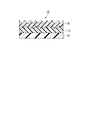
- FIG. 1 is a cross-sectional view showing an example of a laminated structure in the first embodiment.
- the laminated structure 10 of this example is configured by sequentially laminating an intermediate layer 14 and an outermost layer 16 on a base material 12, and has a fine uneven structure on the surface of the intermediate layer 14 and the outermost layer 16.
- the outermost layer is the uppermost layer of the laminated structure
- the base material is the lowermost layer of the laminated structure.
- the surface facing the uppermost layer side is the “upper surface”
- the surface facing the lowermost layer side is the “lower surface”.
- the upper surface of the layer is defined as “the surface of the layer”
- the lower surface of the layer is defined as “the back surface of the layer”.
- the “surface of the outermost layer” is the upper surface of the outermost layer 16, that is, the surface not in contact with the intermediate layer 14. Is the lower surface of the outermost layer 16, that is, the surface of the outermost layer 16 on the side in contact with the intermediate layer 14.
- the “surface of the intermediate layer” is the upper surface of the intermediate layer 14, that is, the surface on the side in contact with the outermost layer 16 of the intermediate layer 14, and the “back surface of the intermediate layer” is the lower surface of the intermediate layer 14, That is, the surface of the intermediate layer 14 on the side in contact with the base material 12.
- the “surface of the base material” is the upper surface of the base material 12, that is, the surface on the side in contact with the intermediate layer 14 of the base material 12, and the “back surface of the base material” is the lower surface of the base material 12. That is, the surface of the substrate 12 on the side not in contact with the intermediate layer 14.
- the surface of the outermost layer 16 corresponds to the surface (uppermost surface) of the laminated structure 10
- the back surface of the substrate 12 corresponds to the back surface (lowermost surface) of the laminated structure.
- the back surface of the outermost layer 16 and the surface of the intermediate layer 14 correspond to the interface between the outermost layer 16 and the intermediate layer 14
- the back surface of the intermediate layer 14 and the surface of the substrate 12 correspond to the interface between the intermediate layer 14 and the substrate 12.
- the concave and convex portions of the fine uneven structure of the outermost layer 16 are arranged differently from the concave and convex portions of the fine uneven structure of the intermediate layer 14.
- “differently arranged” means that the concavo-convex shape of a fine concavo-convex structure of an arbitrary layer (for example, the outermost layer) in one or more cut surfaces obtained by cutting a plurality of laminated structures in the lamination direction (longitudinal direction), This means that when translated in the thickness direction of the laminated structure, it does not overlap with the shape of the fine relief structure of at least one other layer (for example, an intermediate layer).
- the concavo-convex shape of the fine concavo-convex structure of an arbitrary layer overlaps the shape of the fine concavo-convex structure of at least one other layer, and a part thereof may overlap.
- “the shape does not overlap” means that the aspect ratio of the convex portion of the fine concavo-convex structure of an arbitrary layer is different from the aspect ratio of the convex portion of the fine concavo-convex structure of at least one other layer (for example, FIGS. To 6 and 8), and the fine concavo-convex structure of an arbitrary layer and at least one other layer is displaced from each other (see, for example, FIG. 7).
- Each interface of the laminated structure 10, that is, the interface between the base material 12 and the intermediate layer 14 and the interface between the intermediate layer 14 and the outermost layer 16 are not subjected to release treatment.
- the interface is not subjected to mold release treatment means that the surface of the substrate 12, the back and front surfaces of the intermediate layer, and the back surface of the outermost layer 16 are not subjected to mold release treatment.
- release process means that a release agent exemplified in the description of the mold to be described later is applied to the surface of the base material 12, the back and front surfaces of the intermediate layer, and the back surface of the outermost layer 16. Is to form.
- the shape of the concave and convex portions of the fine concavo-convex structure is not particularly limited, but a so-called moth-eye structure in which a plurality of projections (convex portions) such as a substantially conical shape and a pyramid shape are arranged or its inverted structure is preferable.
- a moth-eye structure in which the fine irregularities of the outermost layer 16 have a moth-eye structure in which the average interval between adjacent convex portions is equal to or less than the wavelength of visible light (400 nm), the refractive index is continuously changed from the refractive index of air to the refractive index of the material. Is effective as a means for preventing reflection.
- the reflection at the interface can be suppressed even if the refractive indexes of adjacent layers are different, which is effective in reducing the reflectance and suppressing interference fringes.
- the average interval between adjacent convex portions of the fine concavo-convex structure is preferably the wavelength of visible light or less, that is, 400 nm or less, more preferably 300 nm or less, and more preferably 250 nm or less. Further preferred. If the pitch of the convex portions is 400 nm or less, the reflectance is low and the wavelength dependence of the reflectance is small.
- the pitch of the convex portions is preferably 25 nm or more, and more preferably 80 nm or more from the viewpoint of easy formation of the convex portion structure.
- the average interval between adjacent convex parts measured 50 points
- the average interval between the concave portions or the convex portions of the fine concavo-convex structure of an arbitrary layer is different from the average interval between the concave portions or the convex portions of the other fine concavo-convex structure of at least one layer.
- the average interval between the concave portions or the convex portions of the fine concavo-convex structure of the outermost layer 16 is at least one other layer (in FIG.
- the average distance between the concave portions or the convex portions of the fine uneven structure of the intermediate layer 14) is larger. With such a configuration, the adhesion between the layers is further increased, and the scratch resistance and antifouling property of the surface of the outermost layer 16 (that is, the surface of the laminated structure 10) is improved.
- the average height of the convex portions is 100 nm or more, the reflectance is low and the wavelength dependence of the reflectance is small. Moreover, the adhesiveness between layers can be ensured.
- the average height of the protrusions is preferably 400 nm or less, and more preferably 300 nm or less, from the viewpoint of easy formation of the protrusion structure.
- the average height of the convex portion was measured by measuring the distance between the topmost portion of the convex portion and the bottommost portion of the concave portion existing between the convex portions when observed with the electron microscope, and these values were measured. Is an average value.
- the aspect ratio of the protrusions (average height of the protrusions / average distance between adjacent protrusions) is preferably 0.8 to 5, more preferably 1.2 to 4, and further preferably 1.5 to 3 preferable. If the aspect ratio of the convex portion is 0.8 or more, the reflectance is sufficiently low. When the aspect ratio of the convex portion is 5 or less, the scratch resistance of the convex portion is good.
- the elastic recovery rate of the outermost layer 16 is preferably 70% or more, more preferably 80% or more, and particularly preferably 85% or more.
- the elastic recovery rate of the outermost layer 16 is 70% or more, even if an external force is applied to the outermost layer 16 in the lateral direction, the original state can be easily recovered, so that scratches are hardly formed, and scratch resistance is further improved.
- the outermost layer 16 has a fine concavo-convex structure on its surface, even if an external force is applied to the fine concavo-convex structure in the lateral direction, the convex portion is not easily broken or scraped. More improved.
- the elastic recovery rate of the outermost layer 16 is 70% or more, the outermost layer 16 is difficult to be plastically deformed and the dents are less likely to remain as indentations, so that higher pencil hardness can be maintained.
- the elastic modulus of the outermost layer 16 is preferably 80 MPa or more, and more preferably 120 to 2000 MPa. If the elastic modulus of the outermost layer 16 is 80 MPa or more, the original state can be easily recovered even when an external force is applied to the outermost layer 16, and the scratch resistance is further improved. In particular, when the outermost layer 16 has a fine concavo-convex structure on the surface, even if the fine concavo-convex structure is deformed by applying external force to the fine concavo-convex structure, the convex portion may be broken or scraped. It is difficult to recover and can be easily recovered.
- the elastic recovery rate and elastic modulus of the outermost layer 16 are determined by measuring the elastic recovery rate and elastic modulus of the cured material of the material of the outermost layer 16 (for example, a resin composition for the outermost layer described later) with a microhardness meter. . Specifically, first, a test piece in which a cured product of the material of the outermost layer 16 is formed on a substrate such as a glass plate is produced. Using a Vickers indenter and a micro hardness tester, the evaluation program of [Indentation (100 mN / 10 sec)] ⁇ [Creep (100 mN, 10 sec)] ⁇ [Unloading (100 mN / 10 sec)] Measure physical properties.
- the elastic modulus and elastic recovery rate of the cured product are calculated by analysis software (for example, “WIN-HCU” manufactured by Fischer Instruments Co., Ltd.), and this is calculated as the elastic recovery rate and elasticity of the outermost layer 16. Rate.
- the elastic recovery rate and elastic modulus of the outermost layer can also be determined by measuring the surface on the outermost layer side of the laminated structure at a depth within 1/10 of the thickness of each layer with a microhardness meter. .
- the difference between the refractive index of the intermediate layer 14 and the refractive index of the substrate 12 and the difference between the refractive index of the outermost layer 16 and the refractive index of the intermediate layer 14 are each preferably 0.2 or less, more preferably 0.1 or less. Preferably, 0.05 or less is more preferable. If the difference in refractive index is 0.2 or less, reflection at the interface of each layer can be effectively suppressed.
- the base material 12 which is the lowest layer of the laminated structure, a molded body that transmits light is preferable. Although this will be described in detail later, this is because active energy rays are irradiated from the base material side when a fine concavo-convex structure is formed using a mold that does not easily transmit light.
- the material of the base material 12 include acrylic resins (polymethyl methacrylate, etc.), polycarbonate, styrene (co) polymer, methyl methacrylate-styrene copolymer, cellulose diacetate, cellulose triacetate, and cellulose acetate butyrate.
- Polyester polyethylene terephthalate, etc.
- polyamide polyimide
- polyether sulfone polysulfone
- polyolefin polyethylene, polypropylene, etc.
- polymethylpentene polyvinyl chloride, polyvinyl acetal, polyether ketone, polyurethane, glass and the like.
- the substrate 12 may be an injection molded body, an extrusion molded body, or a cast molded body.
- the shape of the substrate 12 can be selected as appropriate, and may be a sheet or a film.
- the surface of the substrate 12 may be subjected to a coating treatment, a corona treatment or the like in order to improve adhesion, antistatic properties, scratch resistance, weather resistance, and the like.
- the material of the intermediate layer 14 includes an active energy ray curable resin composition, a thermoplastic resin, an inorganic material, and the like.
- a layer made of a cured product of the curable resin composition is preferable.
- the outermost layer 16 is also preferably a layer made of a cured product of the active energy ray-curable resin composition from the viewpoint of easy formation of a fine concavo-convex structure.
- the active energy ray-curable resin composition will be described in detail.
- the active energy ray-curable resin composition for the intermediate layer is referred to as “the resin composition for the intermediate layer”, and the active energy ray-curable resin composition for the outermost layer is also referred to as the “resin composition for the outermost layer”.
- An active energy ray-curable resin composition (hereinafter, sometimes simply referred to as “resin composition”) is a resin composition that cures by irradiating active energy rays and undergoes a polymerization reaction.
- the resin composition suitably contains, as a polymerizable component, for example, a monomer, oligomer, or reactive polymer having a radical polymerizable bond and / or a cationic polymerizable bond in the molecule. Further, the resin composition usually contains a polymerization initiator for curing.
- Examples of the monomer having a radical polymerizable bond in the molecule include (meth) acrylates (methyl (meth) acrylate, ethyl (meth) acrylate, propyl (meth) acrylate, n-butyl (meth) acrylate, i-butyl ( (Meth) acrylate, s-butyl (meth) acrylate, tert-butyl (meth) acrylate, 2-ethylhexyl (meth) acrylate, lauryl (meth) acrylate, alkyl (meth) acrylate, tridecyl (meth) acrylate, stearyl (meth) Acrylate, cyclohexyl (meth) acrylate, benzyl (meth) acrylate, phenoxyethyl (meth) acrylate, isobornyl (meth) acrylate, glycidyl (meth)
- oligomers and reactive polymers having a radical polymerizable bond in the molecule examples include unsaturated polyesters (condensates of unsaturated dicarboxylic acids and polyhydric alcohols), polyester (meth) acrylates, and polyether (meth) acrylates. Polyol (meth) acrylate, epoxy (meth) acrylate, urethane (meth) acrylate, cationic polymerization type epoxy compound, homopolymer or copolymer of the above-mentioned monomer having a radical polymerizable bond in the side chain, and the like. .
- the monomer, oligomer, or reactive polymer having a cationic polymerizable bond in the molecule may be any compound having a cationic polymerizable functional group (cationic polymerizable compound), and may be any of a monomer, an oligomer, and a prepolymer. Also good.
- the cationically polymerizable functional group include highly practical functional groups such as cyclic ether groups (epoxy groups, oxetanyl groups, etc.), vinyl ether groups, carbonate groups (O—CO—O groups), and the like.
- the cationic polymerizable compound include cyclic ether compounds (such as epoxy compounds and oxetane compounds), vinyl ether compounds, and carbonate compounds (such as cyclic carbonate compounds and dithiocarbonate compounds).
- the monomer having a cationic polymerizable bond in the molecule include monomers having an epoxy group, an oxetanyl group, an oxazolyl group, a vinyloxy group, etc. Among these, a monomer having an epoxy group is particularly preferable.
- Specific examples of the oligomer and reactive polymer having a cationic polymerizable bond include a cationic polymerization type epoxy compound.
- Examples of the polymerization initiator include known ones. When the resin composition is cured using a photoreaction, examples of the photopolymerization initiator include a radical polymerization initiator and a cationic polymerization initiator. Any radical polymerization initiator may be used as long as it generates an acid upon irradiation with a known active energy ray. An acetophenone-based photopolymerization initiator, a benzoin-based photopolymerization initiator, a benzophenone-based photopolymerization initiator, or a thioxanthone-based light is used. Examples thereof include polymerization initiators and acylphosphine oxide photopolymerization initiators. These radical polymerization initiators may be used alone or in combination of two or more.
- acetophenone photopolymerization initiator examples include acetophenone, p- (tert-butyl) -1 ′, 1 ′, 1′-trichloroacetophenone, chloroacetophenone, 2 ′, 2′-diethoxyacetophenone, hydroxyacetophenone, 2, Examples include 2-dimethoxy-2′-phenylacetophenone, 2-aminoacetophenone, dialkylaminoacetophenone, and the like.
- benzoin photopolymerization initiator examples include benzyl, benzoin, benzoin methyl ether, benzoin ethyl ether, benzoin isopropyl ether, benzoin isobutyl ether, 1-hydroxycyclohexyl phenyl ketone, 2-hydroxy-2-methyl-1-phenyl-2 -Methylpropan-1-one, 1- (4-isopropylphenyl) -2-hydroxy-2-methylpropan-1-one, benzyldimethyl ketal and the like.
- benzophenone photopolymerization initiator examples include benzophenone, benzoylbenzoic acid, methyl benzoylbenzoate, methyl-o-benzoylbenzoate, 4-phenylbenzophenone, hydroxybenzophenone, hydroxypropylbenzophenone, acrylic benzophenone, 4,4′-bis ( And dimethylamino) benzophenone.
- thioxanthone photopolymerization initiator examples include thioxanthone, 2-chlorothioxanthone, 2-methylthioxanthone, diethylthioxanthone, and dimethylthioxanthone.
- acylphosphine oxide photopolymerization initiator examples include 2,4,6-trimethylbenzoyldiphenylphosphine oxide, benzoyldiethoxyphosphine oxide, bis (2,4,6-trimethylbenzoyl) phenylphosphine oxide, and the like. .
- radical polymerization initiators include, for example, ⁇ -acyl oxime ester, benzyl- (o-ethoxycarbonyl) - ⁇ -monooxime, glyoxy ester, 3-ketocoumarin, 2-ethylanthraquinone, camphorquinone, tetramethylthiuram sulfide Azobisisobutyronitrile, benzoyl peroxide, dialkyl peroxide, tert-butyl peroxypivalate and the like.
- the cationic polymerization initiator is not particularly limited as long as it generates an acid upon irradiation with a known active energy ray, and examples thereof include sulfonium salts, iodonium salts, and phosphonium salts. These cationic polymerization initiators may be used alone or in combination of two or more.
- sulfonium salt examples include triphenylsulfonium hexafluorophosphate, triphenylsulfonium hexafluoroantimonate, bis (4- (diphenylsulfonio) -phenyl) sulfide-bis (hexafluorophosphate), bis (4- (diphenylsulfonio).
- iodonium salt examples include diphenyliodonium hexafluorophosphate, diphenyliodonium hexafluoroantimonate, bis (dodecylphenyl) iodonium tetrakis (pentafluorophenyl) borate, and the like.
- Examples of the phosphonium salt include tetrafluorophosphonium hexafluorophosphate and tetrafluorophosphonium hexafluoroantimonate.
- thermal polymerization initiator examples include organic peroxides (methyl ethyl ketone peroxide, benzoyl peroxide, dicumyl peroxide, tert-butyl hydroperoxide, cumene hydroperoxide, tert-butyl. Peroxyoctate, tert-butylperoxybenzoate, lauroyl peroxide, etc.), azo compounds (azobisisobutyronitrile, etc.), amines (N, N-dimethylaniline, N, N-dimethyl-p) to the organic peroxides.
- thermal polymerization initiators may be used alone or in combination of two or more.
- the content of the polymerization initiator is preferably 0.1 to 10 parts by mass with respect to 100 parts by mass of the polymerizable component. If content of a polymerization initiator is 0.1 mass part or more, superposition
- the resin composition may include a non-reactive polymer.
- non-reactive polymers include acrylic resins, styrene resins, polyurethane resins, cellulose resins, polyvinyl butyral resins, polyester resins, and thermoplastic elastomers.
- the resin composition may include surfactants, mold release agents, lubricants, plasticizers, antistatic agents, light stabilizers, antioxidants, flame retardants, flame retardant aids, if necessary.
- a known additive such as a polymerization inhibitor, a filler, a silane coupling agent, a colorant, a reinforcing agent, an inorganic filler, inorganic or organic fine particles, an impact modifier, and a small amount of a solvent may be contained.
- the viscosity of the resin composition is not too high from the viewpoint of easy flow into the fine concavo-convex structure on the surface of the mold.
- the viscosity of the resin composition measured with a rotary B-type viscometer at 25 ° C. is preferably 10000 mPa ⁇ s or less, more preferably 5000 mPa ⁇ s or less, and further preferably 2000 mPa ⁇ s or less.
- the viscosity of the resin composition measured with a rotary B-type viscometer at 70 ° C. is preferably 5000 mPa ⁇ s or less, and more preferably 2000 mPa ⁇ s or less.
- the lower limit of the viscosity of the resin composition is not particularly limited, but it is preferably 10 mPa ⁇ s or more because a laminated structure can be efficiently produced without wetting and spreading.
- the method for forming the fine concavo-convex structure of the intermediate layer 14 and the outermost layer 16 is not particularly limited. It is preferable to form by contact and curing. According to the transfer method, the shape of the fine concavo-convex structure of each layer can be freely designed. In addition, it is possible to easily manufacture a laminated structure in which the concave and convex portions of the fine concavo-convex structure of any layer are arranged differently from the concave and convex portions of the fine concavo-convex structure of at least one other layer.
- a mold used for the transfer method will be described.
- the mold has an inverted structure of a fine concavo-convex structure on the surface.
- the material for the mold include metals (including those having an oxide film formed on the surface), quartz, glass, resin, ceramics, and the like.
- the shape of the mold include a roll shape, a circular tube shape, a flat plate shape, and a sheet shape.
- Examples of the mold production method include the following method (I-1) and method (I-2). Among these methods, the method (I-1) is preferable from the viewpoint that the area can be increased and the production is simple.
- (I-1) A method of forming an inverted structure of a fine relief structure by a method of forming anodized alumina having a plurality of pores (recesses) on the surface of an aluminum base.
- (I-2) A method of forming an inverted structure of a fine concavo-convex structure on the surface of a mold substrate by an electron beam lithography method, a laser beam interference method, or the like.
- a method including the following steps (a) to (f) is preferable.
- B A step of removing a part or all of the oxide film to form anodic oxidation pore generation points on the surface of the aluminum substrate.
- C After the step (b), the step of anodizing the aluminum substrate again in the electrolytic solution to form an oxide film having pores at the pore generation points.
- D A step of expanding the diameter of the pores after the step (c).
- E A step of anodizing again in the electrolytic solution after the step (d).
- F A step of repeatedly performing steps (d) and (e) to obtain a mold in which anodized alumina having a plurality of pores is formed on the surface of an aluminum substrate.
- Examples of the shape of the aluminum substrate include a roll shape, a circular tube shape, a flat plate shape, and a sheet shape. Since the oil used when processing the aluminum base material into a predetermined shape may be adhered, it is preferable to degrease the aluminum base material in advance. Moreover, it is preferable that the aluminum base material is grind
- the purity of aluminum is preferably 99% or more, more preferably 99.5% or more, and further preferably 99.8% or more. When the purity of aluminum is low, when anodized, an uneven structure having a size to scatter visible light may be formed due to segregation of impurities, or the regularity of pores obtained by anodization may be lowered.
- electrolytic solution examples include sulfuric acid, oxalic acid, phosphoric acid and the like.
- the concentration of oxalic acid is preferably 0.8 M or less. If the concentration of oxalic acid is 0.8 M or less, an increase in current value can be prevented and the surface of the oxide film can be prevented from becoming rough. Further, when the formation voltage is 30 to 100 V, anodized alumina having highly regular pores with a period of 100 nm to 200 nm can be obtained. The regularity tends to decrease whether the formation voltage is higher or lower than this range.
- the temperature of the electrolytic solution is preferably 60 ° C. or lower, and more preferably 45 ° C. or lower. When the temperature of the electrolytic solution is 60 ° C. or lower, it is possible to prevent the so-called “yake” phenomenon from occurring, and to suppress damage to the pores and the disorder of the regularity of the pores due to melting of the surface. Can do.
- the concentration of sulfuric acid is preferably 0.7 M or less. If the concentration of sulfuric acid is 0.7M or less, the current value can be prevented from increasing and a constant voltage can be maintained. Further, when the formation voltage is 25 to 30 V, anodized alumina having highly regular pores with a period of 63 nm can be obtained. The regularity tends to decrease whether the formation voltage is higher or lower than this range.
- the temperature of the electrolytic solution is preferably 30 ° C. or lower, and more preferably 20 ° C. or lower. When the temperature of the electrolytic solution is 30 ° C. or less, it is possible to prevent a phenomenon called “burning” from occurring, and to prevent damage to the pores and the disorder of the regularity of the pores due to melting of the surface. Can do.
- the method for removing the oxide film 24 include a method in which the oxide film 24 is dissolved and removed in a solution that can selectively dissolve the oxide film 24 without dissolving aluminum. Examples of such a solution include a chromic acid / phosphoric acid mixed solution.
- the pore diameter expansion process is a process for expanding the diameter of the pores obtained by anodic oxidation by immersing in a solution capable of dissolving the oxide film 24. Examples of such a solution include a phosphoric acid aqueous solution of about 5% by mass. The longer the pore size expansion processing time, the larger the pore size.
- Examples of the shape of the pore 22 include a substantially conical shape, a pyramid shape, and a cylindrical shape.
- the average distance between adjacent pores 22 is preferably not more than the wavelength of visible light, that is, not more than 400 nm, more preferably 25 to 300 nm, and further preferably 80 to 250 nm.
- the average interval between the adjacent pores 22 is measured by measuring the distance between the adjacent pores 22 (the distance from the center of the pore 22 to the center of the adjacent pore 22) with an electron microscope at 50 points. The average value.
- the average depth of the pores 22 is preferably 100 to 400 nm, and more preferably 130 to 300 nm.
- the average depth of the pores 22 was measured by measuring the distance between the bottom of the pores 22 and the top of the projections existing between the pores 22 when observed by the electron microscope observation, It is a value obtained by averaging these values.
- the aspect ratio of the pores 22 (average depth of the pores 22 / average interval between adjacent pores 22) is preferably 0.3 to 4, and more preferably 0.8 to 2.5.
- the surface of the mold on which the fine concavo-convex structure is formed may be treated with a release agent.
- the release agent include silicone resins, fluororesins, fluorine compounds, and phosphate esters, and fluorine compounds and phosphate esters are preferable.
- fluorine compounds include “Fluorolink” manufactured by Solvay Specialty Polymers Japan Co., Ltd., fluoroalkylsilane “KBM-7803” manufactured by Shin-Etsu Chemical Co., Ltd., “MRAF” manufactured by Asahi Glass Co., Ltd., and Harves Co., Ltd.
- OPTOOL HD1100 “OPTOOL HD2100 series” manufactured by Daikin Industries, Ltd., “Novec EGC-1720” manufactured by Sumitomo 3M Limited, “FS-2050” series manufactured by Fluoro Technology Co., Ltd., etc. Is mentioned.
- a (poly) oxyalkylene alkyl phosphate compound is preferable.
- Commercially available products include “JP-506H” manufactured by Johoku Chemical Industry Co., Ltd., “Mold With INT-1856” manufactured by Accel Corporation, “TDP-10”, “TDP-8”, “TDP” manufactured by Nikko Chemicals Co., Ltd.
- release agents may be used alone or in combination of two or more.
- the fine uneven structure of the laminated structure is the fine uneven structure on the surface of the anodized alumina. It is formed by transferring the structure.
- a manufacturing apparatus for manufacturing a laminated structure and a manufacturing method of the laminated structure using the manufacturing apparatus will be specifically described.
- the laminated structure 10 shown in FIG. 1 is manufactured by the manufacturing method (1) including the following steps (1-1) and (1-2), for example, using the manufacturing apparatus shown in FIG. (1-1) Supplying an active energy ray-curable resin composition for an intermediate layer (resin composition for an intermediate layer) onto a substrate and transferring the fine concavo-convex structure using a mold having a fine concavo-convex structure on the surface Then, after the intermediate layer is formed by curing the resin composition for the intermediate layer to which the fine concavo-convex structure has been transferred by irradiation with active energy rays, the intermediate layer and the mold are peeled off.
- the manufacturing method (1) including the following steps (1-1) and (1-2), for example, using the manufacturing apparatus shown in FIG. (1-1) Supplying an active energy ray-curable resin composition for an intermediate layer (resin composition for an intermediate layer) onto a substrate and transferring the fine concavo-convex structure using a mold having a fine concavo-convex structure on
- step (1-1) After repeating step (1-1) one or more times, supply the outermost active energy ray-curable resin composition (resin composition for the outermost layer) to the surface of the obtained intermediate layer After transferring the fine concavo-convex structure using a mold having the fine concavo-convex structure on the surface, and then curing the resin composition for the outermost layer to which the fine concavo-convex structure was transferred by irradiation with active energy rays, The process of peeling the outermost layer and the mold.
- Step (1-1) As shown in FIG. 3, between the roll-shaped mold 30 having a reversal structure (not shown) of a fine concavo-convex structure on the surface and the substrate 12 that is a strip-shaped film moving along the surface of the roll-shaped mold 30, A resin composition for the intermediate layer is supplied from the tank 32.
- the base 12 and the resin composition for the intermediate layer are nipped between the roll-shaped mold 30 and the nip roll 36 whose nip pressure is adjusted by the pneumatic cylinder 34.
- the resin composition for the intermediate layer spreads uniformly between the base material 12 and the roll-shaped mold 30, and at the same time, is filled into the concave portions of the fine concavo-convex structure of the roll-shaped mold 30, and the fine concavo-convex structure is transferred. .
- An active energy ray is irradiated from the active energy ray irradiating device 38 installed below the roll-shaped mold 30 to the resin composition for the intermediate layer to which the fine concavo-convex structure is transferred via the base material 12, and the resin for the intermediate layer The composition is cured.
- the intermediate layer 14 having a fine concavo-convex structure on which the fine concavo-convex structure on the surface of the roll-shaped mold 30 is transferred is formed.
- a laminate 10 ′ in which the intermediate layer 14 is laminated on the base material 12 is obtained. .
- the obtained laminate 10 ′ is used in the next step without releasing the surface of the intermediate layer 14 (the surface on the fine relief structure side).
- the resin composition for the outermost layer is uniformly distributed between the laminate 10 ′ and the roll-shaped mold 30, and at the same time, is filled into the concave portions of the fine concavo-convex structure of the roll-shaped mold 30, and the fine concavo-convex structure is transferred.
- the resin composition for the outermost layer to which the fine concavo-convex structure is transferred via the substrate 12 is irradiated with active energy rays to cure the resin composition.
- the outermost layer 16 having a fine concavo-convex structure on which the fine concavo-convex structure on the surface of the roll-shaped mold 30 is transferred is formed.
- the laminate 10 ′ having the outermost surface layer 16 having the fine uneven structure on the surface is peeled from the roll-shaped mold 30 by the peeling roll 40, thereby having the fine uneven structure on the surface as shown in FIG.
- the laminated structure 10 in which the intermediate layer 14 and the outermost layer 16 are sequentially laminated on the substrate 12 is obtained.
- the active energy ray irradiation device 38 As the active energy ray irradiation device 38, a high-pressure mercury lamp, a metal halide lamp, an LED lamp or the like is preferable.
- the amount of light irradiation energy is preferably 100 to 10,000 mJ / cm 2 .
- the intermediate layer 14 and the outermost layer 16 may be formed using the same manufacturing apparatus, or may be formed using different manufacturing apparatuses. When the same manufacturing apparatus is used, the manufacturing apparatus can be prevented from increasing in size. In this case, when the shape of the concave and convex portions of the fine concavo-convex structure is different in each layer, the mold is replaced with the outermost layer mold when switching from the formation of the intermediate layer 14 to the formation of the outermost layer 16. When using different manufacturing apparatuses, the intermediate layer 14 and the outermost layer 16 can be formed continuously.
- the laminated structure 10 includes the intermediate layer 14 having the fine concavo-convex structure on the surface, the intermediate layer 14 and the outermost layer 16 adjacent to the intermediate layer 14 are formed by the anchor effect by the fine concavo-convex structure. Excellent adhesion. Further, since the interface of the laminated structure 10 is not subjected to mold release treatment, even if an arbitrary layer is intentionally peeled off, it is difficult to peel off and the adhesion between the layers is high.
- the laminated structure 10 is a grid at intervals of 2.0 mm on the surface (top surface) of the laminated structure 10 in a cross-cut tape peeling test according to JIS K 5600-5-6: 1999 (ISO 2409: 1992).
- the number of cuts that peeled off when peeled is less than 50 squares out of 100 squares Adhesiveness that becomes.
- the laminated structure 10 has a multilayer structure, the scratch resistance is improved, and the mechanical properties of the surface of the laminated structure 10 are enhanced.
- the laminated structure 10 is more excellent in mechanical properties because the intermediate layer 14 is provided between the base material 12 and the outermost layer 16. If the thickness of the intermediate layer 14 is increased, or the intermediate layer 14 is formed of a hard material, a material having a strong restoring force, or a material that absorbs stress, the scratch resistance and pencil of the surface of the laminated structure 10 can be obtained. Hardness tends to be further improved.
- the laminated structure 10 of the first aspect has high adhesion between the layers (the intermediate layer 14 and the outermost layer 16) and is excellent in mechanical properties. Moreover, since the laminated structure 10 has high adhesion between layers, it is not necessary to provide an easy-adhesion layer or a primer layer on the surface of the base material, or to roughen the surface of the base material, and is manufactured at a low cost. it can. Moreover, since the laminated structure 10 of the first aspect has a fine concavo-convex structure on the surface of the outermost layer 16, it is excellent in optical performance such as antireflection performance.
- the intermediate layer resin composition is not cured or cured when the intermediate layer is formed on the substrate.
- weakening there is a known method of weakening this.
- the intermediate layer is formed on the base material by these methods, the surface of the intermediate layer adheres to the transport roll before the outermost layer is formed on the surface of the intermediate layer, or the base material on which the intermediate layer is laminated is stacked. Sometimes blocking occurred.
- the adhesion between the outermost layer 16 and the intermediate layer 14 is excellent. Therefore, since it is not necessary to cure the resin composition for the intermediate layer or weaken the curing, the surface of the intermediate layer 14 adheres to the transport roll, or the base material 12 on which the intermediate layer 14 is laminated. Blocking is unlikely to occur when stacked.
- the fine concavo-convex structure is characterized by the convex pitch, the average convex height, and the aspect ratio which is the balance between the convex pitch and the average convex height.
- the adhesiveness between the layers tends to be better as the pitch of the protrusions is narrower, the average height of the protrusions is higher, and the aspect ratio is higher.
- the larger the pitch of the convex portions, the lower the average height of the convex portions, and the smaller the aspect ratio the more the scratch resistance of the surface of the laminated structure 10 tends to be improved. The phenomenon that the structure collapses hardly occurs.
- the average height of the convex portions of the fine concavo-convex structure is the same in the intermediate layer 14 and the outermost layer 16, but the pitch of the convex portions is higher in the fine concavo-convex structure of the outermost layer 16.
- the fine uneven structure of the intermediate layer 14 is larger and the aspect ratio is smaller in the fine uneven structure of the outermost layer 16 than in the fine uneven structure of the intermediate layer 14.
- a fine concavo-convex structure with a wide convex portion pitch and a small aspect ratio is formed on the surface of the outermost layer 16, and a fine concavo-convex structure with a narrow convex portion pitch and a large aspect ratio is formed on the surface of the intermediate layer 14.
- the laminated structure 10 thus produced has a good balance between scratch resistance and adhesion.
- the pitch of the convex portions of the fine concavo-convex structure is different between the intermediate layer 14 and the outermost layer 16, these fine concavo-convex structures can be misplaced simply by stacking the outermost layer 16 on the intermediate layer 14.
- the shape of the fine concavo-convex structure in each layer can be freely designed.
- the intermediate layer is coated with an arbitrary coating material so as to follow the shape of the surface of the layer (intermediate layer) having a fine concavo-convex structure on the surface
- the surface of the coating layer (outermost layer) formed Will also have a fine concavo-convex structure following the shape of the surface of the underlying layer (intermediate layer).
- the fine uneven structure of each layer is not misplaced.
- the coating layer (outermost layer) is formed so as to follow the shape of the surface of the layer (intermediate layer) having a fine concavo-convex structure on the surface, the coating layer (outermost layer) is likely to have uneven thickness and is uniform.
- a skilled coating technique is required.
- the coating material is not sufficiently filled up to the concave portion of the fine uneven structure of the intermediate layer, and there is a concern that a gap is formed between the intermediate layer and the coating layer (outermost layer).
- the convex part is high (the concave part is deep) or the pitch of the convex part or the concave part is narrow, it is difficult to fill the concave part with the coating material.
- the outermost layer 16 having a uniform thickness can be easily formed by a transfer method. Further, since the resin composition is sufficiently filled up to the concave portion of the intermediate layer 14, it is difficult to form a gap between the intermediate layer 14 and the outermost layer 16. Moreover, the pitch of the convex portions, the average height of the convex portions, and the aspect ratio of the intermediate layer 14 and the outermost layer 16 can be changed by simply changing to a mold when forming the intermediate layer 14 and when forming the outermost layer 16. Different fine concavo-convex structures can be easily formed.
- the laminated structure of the first aspect includes an antireflection article (an antireflection film, an antireflection film, etc.), an optical article (an optical waveguide, a relief hologram, a lens, a polarization separation element, etc.), a cell culture sheet, a super water-repellent article, Application development as a super-hydrophilic article can be expected. Among these, it is particularly suitable for use as an antireflection article.
- antireflection articles include antireflection films and antireflection films provided on the surfaces of image display devices (liquid crystal display devices, plasma display panels, electroluminescence displays, cathode tube display devices, etc.), lenses, show windows, and glasses. And an antireflection sheet.
- image display devices liquid crystal display devices, plasma display panels, electroluminescence displays, cathode tube display devices, etc.
- an antireflection sheet may be directly attached to the image display surface as an antireflection article, and an antireflection film as an antireflection article on the surface of a member constituting the image display surface. May be formed directly, or an antireflection film may be formed on the front plate as an antireflection article.
- the laminated structure of the first aspect is not limited to the one described above.
- the intermediate layer 14 is composed of one layer.
- the intermediate layer 14 may be composed of a plurality of layers.
- the material, film thickness, and physical properties (such as mechanical characteristics and optical performance) of each layer may be the same or different.
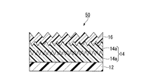
- the laminated structure 50 shown in FIG. 4 is configured by laminating the intermediate layer 14 and the outermost layer 16 in this order on the substrate 12.
- the intermediate layer 14 of the laminated structure 50 includes two layers 14a and 14a having a fine uneven structure on the surface, and the surface of the outermost layer 16 also has a fine uneven structure.
- the concave and convex portions of the fine concavo-convex structure of the outermost layer 16 are arranged differently from the concave and convex portions of the fine concavo-convex structure of the layers 14a and 14a having the fine concavo-convex structure on the surface, constituting the intermediate layer 14, and the surface Further, the fine uneven structure of the layers 14a and 14a having the fine uneven structure is also different in arrangement.
- the pitches and the aspect ratios of the convex portions of all the fine concavo-convex structures are different and all the fine concavo-convex structures are misplaced, but at least two fine concavo-convex structures are misplaced. If there is, the remaining fine concavo-convex structure may not be misplaced with either one of the two fine concavo-convex structures.
- the layers having the fine uneven structure of different arrangement on the surface may be adjacent to each other or may not be adjacent.
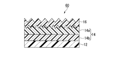
- the laminated structure 60 shown in FIG. 5 is configured by laminating the intermediate layer 14 and the outermost layer 16 in this order on the substrate 12.
- the intermediate layer 14 of the laminated structure 60 is composed of two layers, a layer 14a having a fine uneven structure on the surface and a layer 14b having no fine uneven structure on the surface, and the surface of the outermost layer 16 also has a fine uneven structure.
- the concave and convex portions of the fine uneven structure of the outermost layer 16 are arranged differently from the concave and convex portions of the fine uneven structure of the layer 14 a having the fine uneven structure on the surface, which constitutes the intermediate layer 14.
- Examples of the material of the layer 14b that does not have a fine concavo-convex structure on its surface include thermoplastic resins, active energy ray-curable resin compositions, and inorganic materials.
- the outermost layer 16 and the layer 14a having the fine uneven structure on the surface are adjacent to each other, but the outermost layer 16 and the layer 14b having no fine uneven structure on the surface are formed. It may be adjacent.
- the laminated structure 70 shown in FIG. 6 is configured by laminating the outermost layer 16 on the substrate 12.
- the substrate 12 and the outermost layer 16 of the laminated structure 70 have a fine concavo-convex structure on the surface, and the concave and convex portions of the fine concavo-convex structure of the outermost layer 16 are different from the concave and convex portions of the fine concavo-convex structure of the substrate 12.
- an intermediate layer is preferably provided between the base material 12 and the outermost layer 16 in order to develop more excellent mechanical properties such as scratch resistance.
- the laminated structures 10, 50, 60 and 70 shown in FIGS. 1 and 4 to 6 are different in the pitch and aspect ratio of the convex portions of the fine concavo-convex structure of each layer, but are arranged with at least two fine concavo-convex structures. If they are different, for example, as shown in FIG. 7, the pitches and aspect ratios of the convex portions of the fine concavo-convex structure of each layer may be the same. However, if the pitch of the convex portions of the fine concavo-convex structure of each layer is different, adjustment of adhesion between layers becomes easy.
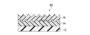
- a laminated structure 80 shown in FIG. 7 is configured by laminating an intermediate layer 14 and an outermost layer 16 in this order on a base material 12.
- the intermediate layer 14 and the outermost layer 16 of the laminated structure 80 have a fine concavo-convex structure on the surface, and the concave and convex portions of the fine concavo-convex structure of the outermost layer 16 are different from the concave and convex portions of the fine concavo-convex structure of the intermediate layer 14. Are arranged. Further, the fine concavo-convex structure of the intermediate layer 14 and the outermost layer 16 has the same pitch of the convex portions, the average height of the convex portions, and the aspect ratio. In this way, if the fine concavo-convex structure having the same convex pitch, convex average height, and aspect ratio is misaligned, unnecessary diffraction and interference derived from the structure can be effectively reduced. it can.
- the laminated structures 10, 50, 60, 70, and 80 shown in FIGS. 1 and 4 to 7 have the same concave and convex shapes of the fine concavo-convex structure of each layer (in the case of FIGS.
- the shape of the concave and convex portions of the fine concavo-convex structure may be different in each layer, and may be appropriately selected according to the effect required for the fine concavo-convex structure.
- these laminated structures 10, 50, 60, 70, and 80 have a fine concavo-convex structure formed on the surface of at least the outermost layer 16, but they may have a fine concavo-convex structure on the surface of at least two layers.
- the fine uneven structure may not be formed on the surface of the outermost layer 16.
- a fine uneven structure may be formed on the back surface of the substrate 12.
- a laminated structure 90 shown in FIG. 8 is configured by laminating an intermediate layer 14 and an outermost layer 16 in this order on a base material 12.
- the intermediate layer 14 of the laminated structure 90 is composed of two layers 14 a and 14 a having a fine uneven structure on the surface, and the surface of the outermost layer 16 does not have a fine uneven structure.
- the concave and convex portions of one fine concavo-convex structure are arranged differently from the concave and convex portions of the other fine concavo-convex structure.
- the outermost layer 16 of the laminated structure 90 may be a coating layer. As shown in FIG. 8, if the intermediate layer 14 adjacent to the coating layer has a fine concavo-convex structure on the surface, the coating layer adheres more closely to the intermediate layer 14.
- a separate film may be provided on the back surface of the substrate 12 via an adhesive layer.
- the pressure-sensitive adhesive layer By providing the pressure-sensitive adhesive layer, it can be easily attached to other film-like or sheet-like articles (front plate, polarizing element, etc.).
- the manufacturing method of a laminated structure is not limited to the manufacturing method (1) mentioned above.
- the laminated structure in which the fine concavo-convex structure is formed on the surface of the outermost layer 16 for example, it can be manufactured by any one of the following manufacturing methods (2) and (3).
- the production method (2) includes the following steps (2-1) and (2-2).
- (2-1) A step of supplying a resin composition for the outermost layer onto the surface of a mold having a fine concavo-convex structure on the surface, and transferring the fine concavo-convex structure of the mold.
- (2-2) A base material on which an intermediate layer having a fine concavo-convex structure on the surface is laminated on the resin composition for the outermost layer on the mold so that the intermediate layer side is in contact, and then the fine concavo-convex structure is transferred.
- the resin composition for the outermost layer is filled in the recesses of the fine uneven structure of the mold, and the fine unevenness of the mold The structure is transferred to the resin composition for the outermost layer.
- the resin composition for the outermost layer is uncured. . Therefore, the uncured resin composition for the outermost layer is easily filled in the recesses of the fine uneven structure of the intermediate layer.
- the outermost layer is formed, and the base material on which the intermediate layer having the fine concavo-convex structure is laminated and the outermost layer are integrated.
- the method of laminating the intermediate layer having the fine concavo-convex structure on the surface is not particularly limited, and for example, the method of the above-mentioned step (1-1) can be mentioned.
- the surface of the intermediate layer is not demolded.
- the production method (3) includes the following steps (3-1) and (3-2).
- (3-1) A resin composition for the outermost layer is provided by supplying a resin composition for the outermost layer onto the surface of the mold having the surface with the fine concavo-convex structure, transferring the fine concavo-convex structure of the mold, and then transferring the fine concavo-convex structure.
- the production method (3) is the same as the production method (2) except that the outermost resin composition to which the fine concavo-convex structure is transferred in the step (3-1) is semi-cured.
- semi-cured refers to a state of being cured to such an extent that it does not flow.
- the viscosity after semi-curing is 10,000 mPa ⁇ s or more, or curing in the step (3-2) ( A hardness of 80% or less with respect to the hardness when fully cured).
- the manufacturing methods (1) to (3) described above are a manufacturing method of a laminated structure including a base material that does not have a fine concavo-convex structure on the surface.
- any one of the following production methods (5) to (7) may be used.
- the production method (5) is a method including the following step (5-1).
- (5-1) Supplying the resin composition for the outermost layer onto the surface of the substrate having the fine concavo-convex structure on the surface, transferring the fine concavo-convex structure using a mold having the fine concavo-convex structure on the surface, A step of peeling the outermost layer from the mold after curing the resin composition for the outermost layer to which the concavo-convex structure has been transferred by irradiation with active energy rays to form the outermost layer.
- step (5-1) a substrate whose surface is not subjected to a release treatment is used.
- step (5-1) an intermediate layer is formed on the surface of the base material before supplying the resin composition for the outermost layer onto the surface of the base material having a fine concavo-convex structure on the surface.
- the method for forming the intermediate layer is not particularly limited, and examples thereof include known methods such as a laminating method, a casting method, a coating method, and a transfer method described later.
- a fine concavo-convex structure may be formed on the surface of the intermediate layer by, for example, a transfer method using a mold such as the step (1-1) described above. Note that the surface of the intermediate layer is not subjected to mold release treatment.
- the production method (6) includes the following steps (6-1) and (6-2).
- (6-1) A step of supplying the resin composition for the outermost layer onto the surface of the mold having the fine concavo-convex structure on the surface, and transferring the fine concavo-convex structure of the mold.
- (6-2) On the resin composition for the outermost layer on the mold, a substrate having a fine concavo-convex structure on the surface is disposed so that the fine concavo-convex structure side is in contact, and then the resin for the outermost layer to which the fine concavo-convex structure is transferred
- the production method (7) includes the following steps (7-1) and (7-2).
- (7-1) The resin for the outermost layer is supplied onto the surface of the mold having the fine concavo-convex structure on the surface, the fine concavo-convex structure of the mold is transferred, and then the resin for the outermost layer is transferred.
- a substrate having a fine concavo-convex structure on the surface is disposed so that the fine concavo-convex structure side is in contact, and then semi-cured resin for the outermost layer A step of peeling the mold from the outermost layer after forming the outermost layer by curing the composition by irradiation with active energy rays.
- a base material whose surface is not subjected to a release treatment is used.
- the base material used in the steps (6-2) and (7-2) may have an intermediate layer laminated on the surface of the base material on the fine concavo-convex structure side.
- the base material on which the intermediate layer is laminated is placed on the resin composition for the outermost layer so as to come into contact with the resin composition for the surface layer.
- the intermediate layer may have a fine uneven structure on the surface.
- the method for laminating the intermediate layer on the substrate is not particularly limited, and examples thereof include known methods such as a laminating method, a casting method, a coating method, and a transfer method described later.
- the method for laminating the intermediate layer having the fine concavo-convex structure on the surface is not particularly limited, and examples thereof include the method of the above-described step (1-1). Note that the surface of the intermediate layer is not subjected to mold release treatment.
- the following manufacturing method (9) when manufacturing a laminated structure in which the fine uneven structure is not formed on the surface of the outermost layer 16, for example, the following manufacturing method (9) may be used.
- the production method (9) includes the following steps (9-1) and (9-2).
- (9-1) The active energy ray-curable resin composition for the intermediate layer is supplied onto the substrate, and the fine concavo-convex structure is transferred using a mold having the fine concavo-convex structure on the surface, and then the fine concavo-convex structure is transferred.
- (9-2) A step of forming the outermost layer on the surface of the obtained intermediate layer after repeating step (9-1) twice or more.
- Step (9-1) is the same as step (1-1) described in the first embodiment. Note that the surface of the intermediate layer 14 is not demolded.
- the method for forming the outermost layer on the surface of the intermediate layer in the step (9-2) is not particularly limited, and examples thereof include known methods such as a laminating method, a casting method, a coating method, and a transfer method. .
- Examples of the laminating method include a method in which the outermost resin composition is extruded on the surface of the intermediate layer in a molten state, laminated, and then cooled by a cooling means such as a cooling roll.
- a cooling means such as a cooling roll.
- the above-mentioned resin composition of the outermost layer is dissolved or dispersed in an organic solvent alone or a mixture such as toluene, MEK, ethyl acetate, etc., and the solid content concentration is 0 to 70% by mass.
- the surface of the intermediate layer is coated with an arbitrary coating material so as not to follow the shape of the surface of the intermediate layer (fine uneven structure), and the coating layer is formed. It may be the outermost layer.
- the fine uneven structure is not formed on the surface of the coating layer (outermost layer) in this case.
- the outermost layer is formed after forming the intermediate layer having the fine concavo-convex structure on the surface on the substrate.
- the fine concavo-convex structure The outermost layer may be formed directly on the surface of the substrate having the surface. Further, after forming one or more intermediate layers on a substrate having a fine concavo-convex structure on the surface, the outermost layer may be formed. In this case, if necessary, a fine uneven structure may be formed on the surface of the intermediate layer by, for example, a mold transfer method.
- the laminated structure in the second aspect of the present invention is configured by laminating two or more layers, and the outermost layer is a layer having no fine uneven structure on the surface, and is formed of at least one layer other than the outermost layer. It has a fine relief structure on the surface.
- FIG. 9 is a cross-sectional view showing an example of the laminated structure in the second mode.
- the laminated structure 100 of this example is configured by sequentially laminating an intermediate layer 14 and an outermost layer 16 on a base material 12, and has a fine uneven structure on the surface of the intermediate layer 14.
- the average interval between the convex portions of the fine concavo-convex structure, the average height, and the aspect ratio are the same as in the first aspect.
- the resin composition constituting the substrate 12, the intermediate layer 14, and the outermost layer 16 is the same as in the first embodiment.
- the interface of the laminated structure may be subjected to release treatment or may not be subjected to release treatment, but is preferably not subjected to release treatment.
- the method for forming the fine concavo-convex structure of the intermediate layer 14 is not particularly limited, but a transfer method using a mold, specifically, contacting the resin composition for the intermediate layer with a mold having an inverted structure of the fine concavo-convex structure on the surface, It is preferable to form by curing.
- the transfer method using the mold and the mold and manufacturing apparatus used at that time are the same as in the first embodiment.
- the laminated structure 100 shown in FIG. 9 is manufactured, for example, by a manufacturing method (4) including the following steps (4-1) and (4-2).
- a manufacturing method (4) including the following steps (4-1) and (4-2).
- (4-1) A resin for an intermediate layer obtained by supplying a resin composition for an intermediate layer onto a substrate, transferring the fine uneven structure using a mold having a fine uneven structure on the surface, and then transferring the fine uneven structure
- (4-2) A step of peeling the intermediate layer and the mold after forming the intermediate layer by curing the composition by irradiation with active energy rays.
- (4-2) A step of forming the outermost layer on the surface of the obtained intermediate layer after repeating step (4-1) one or more times.
- Step (4-1) is the same as step (1-1) described in the first embodiment.
- the surface of the intermediate layer may or may not be released, but it is preferable not to perform the release treatment.
- Step (4-2) is the same as step (9-2) described in the first embodiment.
- the laminated structure 100 according to the second aspect described above includes the intermediate layer 14 having the fine concavo-convex structure on the surface, the intermediate layer 14 and the outermost layer 16 adjacent to the intermediate layer 14 are formed by the anchor effect by the fine concavo-convex structure. Excellent adhesion.
- the laminated structure 100 has adhesiveness such that the number of cuts that are peeled off when the cross-cut tape peeling test described above is performed is less than 50 squares out of 100 squares.
- the laminated structure 10 has a multilayer structure, the scratch resistance is improved, and the mechanical properties of the surface of the laminated structure 100 are enhanced.
- the laminated structure 100 is more excellent in mechanical properties because the intermediate layer 14 is provided between the base material 12 and the outermost layer 16. If the thickness of the intermediate layer 14 is increased, or the intermediate layer 14 is formed of a hard material, a material having a strong restoring force, or a material that absorbs stress, the scratch resistance and pencil of the surface of the laminated structure 10 can be obtained. Hardness tends to be further improved.
- the laminated structure 100 according to the second aspect has high adhesion between the layers (the intermediate layer 14 and the outermost layer 16) and is excellent in mechanical properties.
- the laminated structure 100 has high adhesion between layers, it is not necessary to provide an easy-adhesion layer or primer layer on the surface of the base material, or to roughen the surface of the base material, and is manufactured at a low cost. it can.
- the laminated structure of the second aspect is not limited to the one described above.
- the intermediate layer 14 is composed of one layer, but the intermediate layer 14 may be composed of a plurality of layers.
- the material, film thickness, and physical properties (such as mechanical characteristics and optical performance) of each layer may be the same or different.
- the fine concavo-convex structure may be formed on the surface of two or more layers.
- a fine uneven structure may also be formed on the surface.
- the intermediate layer 14 is composed of a plurality of layers
- a fine uneven structure may be formed on the surface of two or more layers.
- the concave and convex portions of the fine concavo-convex structure of any layer are arranged differently from the concave and convex portions of the fine concavo-convex structure of at least one layer. It is preferable.
- the manufacturing method of a laminated structure is not limited to the manufacturing method (4) mentioned above.
- the manufacturing method (4) described above is a manufacturing method of a laminated structure including a base material that does not have a fine concavo-convex structure on the surface, but a manufacturing method of a laminated structure including a base material that has a fine concavo-convex structure on the surface.
- the following production method (8) may be used.
- the production method (8) is a method including the following step (8-1).
- (8-1) A step of forming an outermost layer on the surface of a substrate having a fine relief structure on the surface.
- Examples of the method for forming the outermost layer on the surface of the substrate in the step (8-1) include the same method as in the step (9-1) described in the first embodiment.
- an intermediate layer may be formed on the surface of the base material before forming the outermost layer on the surface of the base material having the fine uneven structure on the surface.
- the method for forming the intermediate layer is not particularly limited, and examples thereof include known methods such as the laminating molding method, the casting method, the coating method, and the transfer method described above.
- a fine uneven structure may be formed on the surface of the intermediate layer by, for example, a transfer method using a mold such as the step (1-1) described in the first embodiment.
- the film thickness of the laminated film including the substrate and the intermediate layer or / and the outermost layer is measured using a micrometer, and the film thickness of the film in which the substrate or the intermediate layer is laminated is measured.
- the thickness of the intermediate layer and the outermost layer was estimated by subtracting.
- a large slide glass manufactured by Matsunami Glass Industrial Co., Ltd., “Large slide glass, product number: S9213”, 76 mm ⁇ 52 mm size
- the resin composition used in Step 2 was applied so that the thickness of the coating film was about 250 ⁇ m, and this was irradiated with ultraviolet rays at about 1000 mJ / cm 2 using a high-pressure mercury lamp.
- a test piece on which a cured product of the resin composition was formed was prepared. This was used as a test piece for measuring the elastic modulus and elastic recovery rate.
- Adhesion was evaluated according to a cross-cut tape peel test (JIS K 5600-5-6: 1999 (ISO 2409: 1992)) except that the number of cells was 100 and the evaluation criteria were as described below. .
- a transparent black acrylic resin plate Mitsubishi Rayon
- “ACRYLITE EX # 502” (50 mm ⁇ 60 mm) manufactured by Co., Ltd.
- a wear tester (Shinto Kagaku Co., Ltd.) was subjected to a load of 400 g on 2 cm square steel wool (manufactured by Nippon Steel Wool Co., Ltd., “Bonster # 0000”) placed on the surface of a laminated structure having a fine uneven structure on the surface.
- a company-made “HEiDON TRIBOGEAR TYPE-30S”) was used, and reciprocating wear was performed 10 times at a reciprocating distance of 30 mm and a head speed of 30 mm / sec. Thereafter, the appearance of the surface of the laminated structure was evaluated.
- a 2.0 mm thick black acrylic resin plate (manufactured by Mitsubishi Rayon Co., Ltd.) is transparent to the back surface of the laminated structure (the back surface of the base material on which the fine concavo-convex structure is not transferred) via an optical adhesive.
- “Acrylite EX # 502” 50 mm ⁇ 60 mm was affixed and visually observed indoors over a fluorescent lamp, and scratch resistance was evaluated according to the following evaluation criteria. (Double-circle): A crack is not confirmed. ⁇ : The number of scratches that can be confirmed is less than 5, and the scratched site is not white and cloudy.
- a black acrylic resin plate with a thickness of 2.0 mm (Mitsubishi Rayon Co., Ltd.) transparent to the back surface of the laminated structure having a fine concavo-convex structure on the surface (the back surface of the base material on which the fine concavo-convex structure is not transferred) via an optical adhesive.
- “Acrylite EX # 502”, 50 mm ⁇ 60 mm) was pasted and used as a sample.
- UV-2450 manufactured by Shimadzu Corporation
- the visible light reflectance was calculated in accordance with JIS R 3106: 1998 (ISO 9050: 1990), and the antireflection property was evaluated.
- a transparent glass plate (manufactured by Matsunami Glass Industrial Co., Ltd., “Large slide glass”) is attached to the back surface of the laminated structure having a fine concavo-convex structure on the surface (the back surface of the base material on which the fine concavo-convex structure is not transferred) via an optical adhesive. , Product number: S9112 ”, 76 mm ⁇ 52 mm size), and this was used as a sample. Using a haze meter (“NDH2000” manufactured by Nippon Denshoku Industries Co., Ltd.), the haze of the sample was measured and the transparency was evaluated.
- NDH2000 manufactured by Nippon Denshoku Industries Co., Ltd.
- Mold manufacturing Manufacture of mold A
- a 0.3 M oxalic acid aqueous solution was adjusted to 16 ° C., and an aluminum base material was immersed in the solution, and anodization was performed at 40 V DC for 30 minutes. This formed the oxide film which has a pore in an aluminum base material (process (a)).
- the aluminum substrate on which the oxide film was formed was immersed for 6 hours in a 70 ° C.
- step (b) The aluminum base material from which the oxide film was dissolved and removed was immersed in a 0.3 M oxalic acid aqueous solution adjusted to 16 ° C. and anodized at 40 V for 30 seconds (step (c)). Then, it was immersed for 8 minutes in 5 mass% phosphoric acid aqueous solution adjusted to 32 degreeC, and the pore diameter expansion process which expands the pore of an oxide film was performed (process (d)).
- step (e) and (f) substantially conical pores having an average interval of 100 nm and an average depth of 180 nm are formed.
- a mold having anodized alumina on the surface was obtained.
- the mold obtained was immersed in a release agent (0.1% by weight aqueous solution of “TDP-8” manufactured by Nikko Chemicals Co., Ltd.) for 10 minutes, then pulled up and air-dried overnight to release the mold.
- a treated mold A was obtained.
- the aluminum substrate on which the oxide film was formed was immersed for 6 hours in a 70 ° C. aqueous solution in which 6% by mass of phosphoric acid and 1.8% by mass of chromic acid were mixed. Thereby, the oxide film was dissolved and removed (step (b)).
- the aluminum base material from which the oxide film had been dissolved and removed was immersed in a 0.05M oxalic acid aqueous solution adjusted to 16 ° C. and anodized at 80 V for 7 seconds (step (c)). Subsequently, it was immersed in a 5% by mass phosphoric acid aqueous solution adjusted to 32 ° C.
- step (d) the anodization and the pore diameter enlargement process are alternately repeated, and a total of 5 times is applied (steps (e) and (f)) to form substantially conical pores having an average interval of 180 nm and an average depth of 180 nm.
- a mold having anodized alumina on the surface was obtained. The mold obtained was immersed in a release agent (0.1% by weight aqueous solution of “TDP-8” manufactured by Nikko Chemicals Co., Ltd.) for 10 minutes, then pulled up and air-dried overnight to release the mold. A processed mold B was obtained.
- Preparation of active energy ray-curable resin composition (Preparation of active energy ray-curable resin composition A)
- a polymerizable component 20 parts by mass of dipentaerythritol hexaacrylate (manufactured by Nippon Kayaku Co., Ltd., “DPHA”), 20 parts by mass of pentaerythritol triacrylate (manufactured by Daiichi Kogyo Seiyaku Co., Ltd., “New Frontier PET-3”),
- As a polymerization initiator 35 parts by mass of polyethylene glycol diacrylate (manufactured by Shin-Nakamura Chemical Co., Ltd., “A-200”) and 25 parts by mass of N, N-dimethylacrylamide (manufactured by Kojin Co., Ltd., “DMAA”) 1.0 parts by mass of 1-hydroxycyclohexyl phenyl ketone (manufactured by Ciba Japan, “IRGACURE184”), and
- Example 1 (Step 1: Formation of intermediate layer) Several drops of the resin composition A were dropped on the surface of the mold A. The resin composition A was covered with a TAC film while spreading the resin composition A with a 80 ⁇ m thick triacetyl cellulose film (Fuji Film Co., Ltd., “TD80ULM”, hereinafter also referred to as “TAC film”) as a base material. . Thereafter, the resin composition A was cured by irradiating ultraviolet rays with an energy of 1000 mJ / cm 2 using a high-pressure mercury lamp from the TAC film side.
- TAC film triacetyl cellulose film
- the cured product of the resin composition A is released from the mold A together with the TAC film, and the average interval between adjacent convex portions is 100 nm and the average height of the convex portions is 180 nm (aspect ratio: 1.8) on the substrate. ), A laminated film having a 3 ⁇ m-thick intermediate layer laminated thereon was obtained.
- the cured product of the resin composition B is released from the mold together with the laminated film, and on the intermediate layer of the laminated film, the average interval between adjacent convex parts is 180 nm, and the average height of the convex parts is 180 nm (aspect ratio: 1 0.0) on the surface, a film-like laminated structure in which the outermost layer having a thickness of 8 ⁇ m was laminated was obtained.
- the fine concavo-convex structure formed on the surface of the intermediate layer and the outermost layer was misplaced.
- the elastic modulus and elastic recovery rate of the cured product of the resin composition used in step 2 were measured and used as the elastic modulus and elastic recovery rate of the outermost layer.
- Table 1 About the obtained laminated structure, adhesiveness and scratch resistance were evaluated, and reflectance, haze, and blocking resistance were measured. The results are shown in Table 2.
- Example 2 Example 1 except that in Step 1, the TAC film was changed to an acrylic film (manufactured by Mitsubishi Rayon Co., Ltd., “Acryprene”, thickness 100 ⁇ m), and in Step 2, the resin composition B was changed to the resin composition C. Similarly, a laminated structure was manufactured, and various measurements and evaluations were performed. The results are shown in Tables 1 and 2. In addition, the average interval between adjacent convex portions of the fine concavo-convex structure formed on the surface of the intermediate layer and the outermost layer, the average height of the convex portions, and the aspect ratio are the same as those in Example 1, and the intermediate layer and the outermost layer are The fine concavo-convex structure formed on the surface was misplaced.
- Example 3 In step 2, a laminated structure was produced in the same manner as in Example 1 except that the mold B was changed to the mold A and the resin composition B was changed to the resin composition D, and various measurements and evaluations were performed. The results are shown in Tables 1 and 2.
- the average interval between adjacent convex parts of the fine concavo-convex structure formed on the surface of the intermediate layer, the average height of the convex parts, and the aspect ratio are the same as those in Example 1, and are formed on the surface of the outermost layer.
- the average interval between adjacent convex portions of the fine concavo-convex structure was 100 nm, the average height of the convex portions was 180 nm, and the aspect ratio was 1.8. Further, the fine uneven structure formed on the surface of the intermediate layer and the outermost layer was misplaced.
- Example 4" In step 1, a laminated structure was produced in the same manner as in Example 1 except that the TAC film was changed to an acrylic film and the resin composition A was changed to the resin composition E, and various measurements and evaluations were performed. The results are shown in Tables 1 and 2. In addition, the average interval between adjacent convex portions of the fine concavo-convex structure formed on the surface of the intermediate layer and the outermost layer, the average height of the convex portions, and the aspect ratio are the same as those in Example 1, and the intermediate layer and the outermost layer are The fine concavo-convex structure formed on the surface was misplaced.
- Example 5" In the same manner as in Example 1 except that the TAC film was changed to an acrylic film in Step 1, the resin composition A was changed to the resin composition E, and the resin composition B was changed to the resin composition C in Step 2. A laminated structure was manufactured, and various measurements and evaluations were performed. The results are shown in Tables 1 and 2. In addition, the average interval between adjacent convex portions of the fine concavo-convex structure formed on the surface of the intermediate layer and the outermost layer, the average height of the convex portions, and the aspect ratio are the same as those in Example 1, and the intermediate layer and the outermost layer are The fine concavo-convex structure formed on the surface was misplaced.
- Step 1 the same procedure as in Example 1 was performed except that the mold A was changed to a mirror-surface aluminum base material (hereinafter simply referred to as “mirror-surface aluminum base material”) in which the inverted structure of the fine concavo-convex structure was not formed on the surface.
- mirror-surface aluminum base material a mirror-surface aluminum base material
- a laminated structure was manufactured, and various measurements and evaluations were performed. The results are shown in Tables 1 and 2.
- the average interval between adjacent convex portions of the fine concavo-convex structure formed on the surface of the outermost layer, the average height of the convex portions, and the aspect ratio were the same as those in Example 1.
- Example 2 Lamination was performed in the same manner as in Example 1 except that the mold A was changed to a mirror aluminum substrate in Step 1, the TAC film was changed to an acrylic film, and the resin composition B was changed to the resin composition C in Step 2. A structure was manufactured, and various measurements and evaluations were performed. The results are shown in Tables 1 and 2. In addition, the average interval between adjacent convex portions of the fine concavo-convex structure formed on the surface of the outermost layer, the average height of the convex portions, and the aspect ratio were the same as those in Example 1.
- Example 3 In the same manner as in Example 1 except that the mold A is changed to a mirror-finished aluminum substrate in the step 1, the mold B is changed to the mold A in the step 2, and the resin composition B is changed to the resin composition D. A laminated structure was produced, a laminated structure was produced, and various measurements and evaluations were performed. The results are shown in Tables 1 and 2. The average interval between adjacent convex portions of the fine concavo-convex structure formed on the surface of the outermost layer was 100 nm, the average height of the convex portions was 180 nm, and the aspect ratio was 1.8.
- “Comparative Example 4” In step 1, the laminated structure was prepared in the same manner as in Example 1 except that the mold A was changed to a mirror aluminum substrate, the TAC film was changed to an acrylic film, and the resin composition A was changed to the resin composition E. Manufactured and measured and evaluated. The results are shown in Tables 1 and 2. In addition, the average interval between adjacent convex portions of the fine concavo-convex structure formed on the surface of the outermost layer, the average height of the convex portions, and the aspect ratio were the same as those in Example 1.
- step 1 the mold A is changed to a mirror aluminum substrate, the TAC film is changed to an acrylic film, the resin composition A is changed to the resin composition E, and the resin composition B is changed to the resin composition C in step 2.
- a laminated structure was manufactured in the same manner as in Example 1 except that various measurements and evaluations were performed. The results are shown in Tables 1 and 2. In addition, the average interval between adjacent convex portions of the fine concavo-convex structure formed on the surface of the outermost layer, the average height of the convex portions, and the aspect ratio were the same as those in Example 1.
- the film-like laminated structure in which the outermost layer having a film thickness of 3 ⁇ m was laminated on the surface was obtained.
- Various measurements and evaluations were performed on the obtained laminated structure in the same manner as in Example 1. The results are shown in Tables 1 and 2.
- Reference Example 2 A laminated structure was produced in the same manner as in Reference Example 1 except that the TAC film was changed to an acrylic film, and various measurements and evaluations were performed. The results are shown in Tables 1 and 2. In addition, the average interval between adjacent convex portions of the fine concavo-convex structure formed on the surface of the outermost layer, the average height of the convex portions, and the aspect ratio were the same as in Reference Example 1.
- Reference Example 3 A laminated structure was produced in the same manner as in Reference Example 1 except that the mold A was changed to the mold B and the resin composition A was changed to the resin composition B, and various measurements and evaluations were performed. The results are shown in Tables 1 and 2. The average interval between adjacent convex portions of the fine concavo-convex structure formed on the surface of the outermost layer was 180 nm, the average height of the convex portions was 180 nm, and the aspect ratio was 1.0.
- Reference Example 4 A laminated structure was produced in the same manner as in Reference Example 1 except that the TAC film was changed to an acrylic film, the mold A was changed to the mold B, and the resin composition A was changed to the resin composition C. Evaluation was performed. The results are shown in Tables 1 and 2. The average interval between adjacent convex portions of the fine concavo-convex structure formed on the surface of the outermost layer was 180 nm, the average height of the convex portions was 180 nm, and the aspect ratio was 1.0.
- TAC refers to a TAC film
- acrylic refers to an acrylic film
- mirror surface refers to a mirror aluminum substrate.
- the laminated structures of Examples 1 to 5 having fine uneven structures with different arrangements on the surface of the intermediate layer and the outermost layer have good adhesion, scratch resistance, and reflection. It had prevention and transparency. Moreover, it was excellent in blocking resistance.
- the laminated structures of Comparative Examples 1 to 5 in which the fine uneven structure was not formed on the surface of the intermediate layer had the same degree of antireflection and transparency as the laminated structures of the examples. The adhesion between the intermediate layer and the outermost layer was inferior, and peeling occurred on the outermost layer during an abrasion test for evaluating scratch resistance.
- the resin composition A having excellent adhesion to the substrate has poor scratch resistance
- the resin composition has good scratch resistance.
- the thing C was inferior to the adhesiveness to a base material. From these results, it was shown that, according to the present invention, it is possible to achieve both adhesion and scratch resistance by having a specific fine concavo-convex structure on the surface of two or more layers.
- the laminated structure of the present invention has high adhesion between layers and is useful as an optical article excellent in optical performance and mechanical properties, particularly as an antireflection article such as an antireflection film.
- Laminated structure 10 Laminated body 12
- Substrate 14 Intermediate layer 14a Layer having fine concavo-convex structure on surface 14b Layer having no fine concavo-convex structure on surface 16
- Outermost layer 20 Aluminum substrate 22
- Pore 24 Oxide film 26
- Pore generation point 28 Mold 30
- Tank 34 Pneumatic cylinder 36
- Nip roll 38 Active energy ray irradiation device 40 Peeling roll
Landscapes
- Physics & Mathematics (AREA)
- General Physics & Mathematics (AREA)
- Optics & Photonics (AREA)
- Engineering & Computer Science (AREA)
- Mechanical Engineering (AREA)
- Chemical & Material Sciences (AREA)
- Inorganic Chemistry (AREA)
- Manufacturing & Machinery (AREA)
- Plasma & Fusion (AREA)
- Thermal Sciences (AREA)
- Laminated Bodies (AREA)
- Surface Treatment Of Optical Elements (AREA)
Abstract
Description
本願は、2012年10月22日に、日本に出願された特願2012-232808号、に基づき優先権を主張し、その内容をここに援用する。
(i)微細凹凸構造の反転構造を表面に有するモールドを用い、熱可塑性樹脂を射出成形またはプレス成形する際に、熱可塑性樹脂に微細凹凸構造を転写する方法。
(ii)微細凹凸構造の反転構造を表面に有するモールドと基材との間に、活性エネルギー線硬化性樹脂組成物を充填し、活性エネルギー線の照射によって硬化させた後、モールドを離型して硬化物に微細凹凸構造を転写する方法。または、前記モールドと基材との間に、活性エネルギー線硬化性樹脂組成物を充填した後、モールドを離型して活性エネルギー線硬化性樹脂組成物に微細凹凸構造を転写し、その後、活性エネルギー線の照射によって活性エネルギー線硬化性樹脂組成物を硬化させる方法。
(ii)の方法に用いる活性エネルギー線硬化性樹脂組成物としては、例えば、下記の組成物が提案されている。
ウレタンアクリレート等のアクリレートオリゴマーと、ラジカル重合性の官能基を有するアクリル系樹脂と、離型剤と、光重合開始剤とを含む光硬化性樹脂組成物(特許文献1)。
トリメチロールプロパントリ(メタ)アクリレート等の多官能(メタ)アクリレートと、光重合開始剤と、ポリエーテル変性シリコーンオイル等のレベリング剤とを含む紫外線硬化性樹脂組成物(特許文献2)。
しかし、活性エネルギー線硬化性樹脂組成物の硬化物からなる層(硬化層)と基材との密着性は必ずしも十分ではなかった。また、硬化層の表面に微細凹凸構造が形成されている場合、光学性能や機械特性(耐擦傷性や鉛筆硬度等)などを実用レベルで全て付与することは困難であった。
また、反射防止性能と機械特性(耐擦傷性や鉛筆硬度)を両立させる方法としては、微細凹凸構造を転写した活性エネルギー硬化性樹脂組成物の硬化層と基材との間に中間層を設ける方法が知られている(特許文献3)。
また、基材の屈折率が高い場合であっても反射率を充分に低くできる方法として、微細凹凸構造を転写した活性エネルギー硬化性樹脂組成物の硬化層と基材との間に、硬化層と基材の間の屈折率を有する層を積層する方法が知られている(特許文献4)。
また、基材の表面を粗面化処理する場合、加工費が嵩むという問題に加え、粗面化によって基材のヘイズが高くなることで、光学検査によって基材上の異物や欠陥を検出することが困難になるという問題があった。さらに、活性エネルギー硬化性樹脂組成物が基材の粗面に十分に追随できなくなり、硬化層と基材との間に空隙欠陥が発生しやすくなるという問題があった。
また、特許文献3、4に記載のように、基材と硬化層との間に中間層を設ける場合、中間層と硬化層との密着性が不十分となりやすかった。特に、中間層も活性エネルギー線硬化性樹脂組成物の硬化物からなる層である場合には、表面に微細凹凸構造を有する硬化層と、中間層との層間の密着性を高めることが困難であった。
<1> 2つ以上の層が積層された積層構造体であって、少なくとも2つの層の表面に微細凹凸構造を有し、かつ任意の層の微細凹凸構造の凹部および凸部が、他の少なくとも1つの層の微細凹凸構造の凹部および凸部と異なって配置され、界面が離型処理されていない、積層構造体。
<2> 任意の層の微細凹凸構造の凹部間または凸部間の平均間隔が、他の少なくとも1つの層の微細凹凸構造の凹部間または凸部間の平均間隔と異なる、前記<1>に記載の積層構造体。
<3> 少なくとも最表層の表面に前記微細凹凸構造を有する、前記<1>または<2>に記載の積層構造体。
<4> 最表層の微細凹凸構造の凹部間または凸部間の平均間隔が、他の少なくとも1つの層の微細凹凸構造の凹部間または凸部間の平均間隔よりも大きい、前記<3>に記載の積層構造体。
<5> 2つ以上の層が積層された積層構造体であって、最表層は表面に微細凹凸構造を有さない層であり、最表層以外の少なくとも1つの層の表面に微細凹凸構造を有する、積層構造体。
<6> 最表層が、表面に微細凹凸構造を有さないコーティング層である、前記<1>、<2>、<5>のいずれか1つに記載の積層構造体。
<7> 最表層の弾性回復率が70%以上である、前記<1>~<6>のいずれか1つに記載の積層構造体。
<8> 最表層の弾性率が80MPa以上である、前記<1>~<7>のいずれか1つに記載の積層構造体。
<9> 前記微細凹凸構造を表面に有する層が、活性エネルギー線硬化性樹脂組成物の硬化物からなる層である、前記<1>~<8>のいずれか1つに記載の積層構造体。
<10> 前記活性エネルギー線硬化性樹脂組成物が(メタ)アクリレート類を含む、前記<9>に記載の積層構造体。
<11> JIS K 5600-5-6:1999(ISO 2409:1992)に準じたクロスカットテープ剥離試験において、2.0mm間隔で碁盤目状の切れ込みを100マス形成し、この切れ込みに粘着テープを貼着した後、剥離したときに剥がれる切れ込みの数が100マスのうち50マス未満である、前記<1>~<10>のいずれか1つに記載の積層構造体。
<12> 前記<1>~<11>のいずれか1つに記載の積層構造体を表面に備えた、物品。
<14> 前記<1>~<4>のいずれか1つに記載の積層構造体の製造方法であって、下記工程(1-1)、(1-2)を含む、積層構造体の製造方法。
(1-1)基材上に中間層用の活性エネルギー線硬化性樹脂組成物を供給し、微細凹凸構造を表面に有するモールドを用いて微細凹凸構造を転写し、次いで微細凹凸構造を転写した中間層用の活性エネルギー線硬化性樹脂組成物を活性エネルギー線の照射により硬化して中間層を形成した後に、中間層とモールドを剥離する工程。
(1-2)工程(1-1)を1回以上繰り返した後、得られた中間層の表面に最表層用の活性エネルギー線硬化性樹脂組成物を供給し、微細凹凸構造を表面に有するモールドを用いて微細凹凸構造を転写し、次いで微細凹凸構造を転写した最表層用の活性エネルギー線硬化性樹脂組成物を活性エネルギー線の照射により硬化して最表層を形成した後に、最表層とモールドを剥離する工程。
<15> 前記<1>~<4>のいずれか1つに記載の積層構造体の製造方法であって、下記工程(2-1)、(2-2)を含む、積層構造体の製造方法。
(2-1)微細凹凸構造を表面に有するモールドの該表面上に最表層用の活性エネルギー線硬化性樹脂組成物を供給し、モールドの微細凹凸構造を転写する工程。
(2-2)モールド上の最表層用の活性エネルギー線硬化性樹脂組成物上に、微細凹凸構造を表面に有する中間層が積層した基材を中間層側が接するように配置し、次いで微細凹凸構造を転写した最表層用の活性エネルギー線硬化性樹脂組成物を活性エネルギー線の照射により硬化して最表層を形成した後に、最表層とモールドを剥離する工程。
<16> 前記<1>~<4>のいずれか1つに記載の積層構造体の製造方法であって、下記工程(3-1)、(3-2)を含む、積層構造体の製造方法。
(3-1)微細凹凸構造を表面に有するモールドの該表面上に最表層用の活性エネルギー線硬化性樹脂組成物を供給し、モールドの微細凹凸構造を転写し、次いで微細凹凸構造を転写した最表層用の活性エネルギー線硬化性樹脂組成物を活性エネルギー線の照射により半硬化する工程。
(3-2)モールド上の半硬化した最表層用の活性エネルギー線硬化性樹脂組成物上に、微細凹凸構造を表面に有する中間層が積層した基材を中間層側が接するように配置し、次いで半硬化した最表層用の活性エネルギー線硬化性樹脂組成物を活性エネルギー線の照射により硬化して最表層を形成した後に、最表層とモールドを剥離する工程。
<17> 前記<5>に記載の積層構造体の製造方法であって、下記工程(4-1)、(4-2)を含む積層構造体の製造方法。
(4-1)基材上に中間層用の活性エネルギー線硬化性樹脂組成物を供給し、微細凹凸構造を表面に有するモールドを用いて微細凹凸構造を転写し、次いで微細凹凸構造を転写した中間層用の活性エネルギー線硬化性樹脂組成物を活性エネルギー線の照射により硬化して中間層を形成した後に、中間層とモールドを剥離する工程。
(4-2)工程(4-1)を1回以上繰り返した後、得られた中間層の表面に最表層を形成する工程。
<18> 前記<1>~<4>のいずれか1つに記載の積層構造体の製造方法であって、下記工程(5-1)を含む、積層構造体の製造方法。
(5-1)微細凹凸構造を表面に有する基材の該表面上に最表層用の活性エネルギー線硬化性樹脂組成物を供給し、微細凹凸構造を表面に有するモールドを用いて微細凹凸構造を転写し、次いで微細凹凸構造を転写した最表層用の活性エネルギー線硬化性樹脂組成物を活性エネルギー線の照射により硬化して最表層を形成した後に、最表層とモールドを剥離する工程。
<19> 前記微細凹凸構造を表面に有する基材の該表面上に最表層用の活性エネルギー線硬化性樹脂組成物を供給する前に、該基材の表面上に中間層を形成する、前記<18>に記載の積層構造体の製造方法。
<20> 前記中間層の表面にモールドを用いた転写法により微細凹凸構造を形成する、前記<19>に記載の積層構造体の製造方法。
<21> 前記<1>~<4>のいずれか1つに記載の積層構造体の製造方法であって、下記工程(6-1)、(6-2)を含む、積層構造体の製造方法。
(6-1)微細凹凸構造を表面に有するモールドの該表面上に最表層用の活性エネルギー線硬化性樹脂組成物を供給し、モールドの微細凹凸構造を転写する工程。
(6-2)モールド上の最表層用の活性エネルギー線硬化性樹脂組成物上に、微細凹凸構造を表面に有する基材を微細凹凸構造側が接するように配置し、次いで微細凹凸構造を転写した最表層用の活性エネルギー線硬化性樹脂組成物を活性エネルギー線の照射により硬化して最表層を形成した後に、最表層とモールドを剥離する工程。
<22> 微細凹凸構造を表面に有する基材の該表面に、中間層が積層している前記<21>に記載の積層構造体の製造方法。
<23> 前記中間層は表面に微細凹凸構造を有する前記<22>に記載の積層構造体の製造方法。
<24> 前記<1>~<4>のいずれか1つに記載の積層構造体の製造方法であって、下記工程(7-1)、(7-2)を含む、積層構造体の製造方法。
(7-1)微細凹凸構造を表面に有するモールドの該表面上に最表層用の活性エネルギー線硬化性樹脂組成物を供給し、モールドの微細凹凸構造を転写し、次いで微細凹凸構造を転写した最表層用の活性エネルギー線硬化性樹脂組成物を活性エネルギー線の照射により半硬化する工程。
(7-2)モールド上の半硬化した最表層用の活性エネルギー線硬化性樹脂組成物上に、微細凹凸構造を表面に有する基材を微細凹凸構造側が接するように配置し、次いで半硬化した最表層用の活性エネルギー線硬化性樹脂組成物を活性エネルギー線の照射により硬化して最表層を形成した後に、最表層とモールドを剥離する工程。
<25> 微細凹凸構造を表面に有する基材の該表面に、中間層が積層している前記<24>に記載の積層構造体の製造方法。
<26> 前記中間層は表面に微細凹凸構造を有する前記<25>に記載の積層構造体の製造方法。
<27> 前記<5>に記載の積層構造体の製造方法であって、下記工程(8-1)を含む積層構造体の製造方法。
(8-1)微細凹凸構造を表面に有する基材の該表面に最表層を形成する工程。
<28> 前記微細凹凸構造を表面に有する基材の該表面上に最表層を形成する前に、該基材の表面上に中間層を形成する、前記<27>に記載の積層構造体の製造方法。
<29> 前記中間層の表面にモールドを用いた転写法により微細凹凸構造を形成する、前記<28>に記載の積層構造体の製造方法。
本発明の積層構造体の製造方法によれば、層間の密着性が高く、かつ機械特性に優れた層構造体を低コストで容易に製造できる。
本発明の物品は、機械特性に優れる。
なお、本明細書において、積層構造体の最上層を「最表層」といい、最下層を「基材」または「基材層」といい、最表層と基材との間に配置される層を「中間層」という。
また、本明細書において、「層の表面」には、隣接する2層の界面も含まれる。
また、本明細書における「活性エネルギー線」とは、可視光線、紫外線、電子線、プラズマ、熱線(赤外線等)等を意味する。
また、本明細書における「(メタ)アクリレート」は、アクリレートおよびメタクリレートの総称であり、「(メタ)アクリル酸」は、アクリル酸およびメタクリル酸の総称であり、「(メタ)アクリロニトリル」は、アクリロニトリルおよびメタクリロニトリルの総称であり、「(メタ)アクリルアミド」は、アクリルアミドおよびメタクリルアミドの総称である。
図1、4~9においては、各層を図面上で認識可能な程度の大きさとするため、各層ごとに縮尺を異ならせてある。
また、図2~9において、図1と同じ構成要素には同一の符号を付して、その説明を省略する場合がある。
<<第1の態様>>
本発明の第1の態様における積層構造体は、2つ以上の層が積層されて構成され、少なくとも2つの層の表面に微細凹凸構造を有する。また、任意の層の微細凹凸構造の凹部および凸部が、他の少なくとも1つの層の微細凹凸構造の凹部および凸部と異なって配置されている。以下、この配置の状態を「配置違い」ともいう。さらに、第1の態様における積層構造体は、界面が離型処理されていないことを特徴とする。
この例の積層構造体10は、基材12上に、中間層14と最表層16とが順に積層して構成され、中間層14と最表層16の表面に微細凹凸構造を有する。
上述したように、最表層は積層構造体の最上層であり、基材は積層構造体の最下層である。積層構造体を構成する各層において、最上層側を向いている面が「上面」であり、最下層側を向いている面が「下面」である。本発明においては、層の上面を「層の表面」とし、層の下面を「層の裏面」とする。
最表層16の表面は積層構造体10の表面(最上面)に相当し、基材12の裏面は積層構造体の裏面(最下面)に相当する。また、最表層16の裏面と中間層14の表面は最表層16と中間層14の界面に相当し、中間層14の裏面と基材12の表面は中間層14と基材12の界面に相当する。
ここで、「異なって配置」とは、積層構造体を積層方向(縦方向)に複数切断した切断面の1つ以上において、任意の層(例えば最表層)の微細凹凸構造の凹凸形状が、積層構造体の厚さ方向に平行移動したときに、他の少なくとも1つの層(例えば中間層)の微細凹凸構造の形状と重ならないことを意味する。なお、任意の層の微細凹凸構造の凹凸形状の全てが、他の少なくとも1つの層の微細凹凸構造の形状と重ならない状態である必要は必ずしもなく、一部は重なっていてもよい。また「形状が重ならない」とは、任意の層の微細凹凸構造の凸部のアスペクト比と、他の少なくとも1つの層の微細凹凸構造の凸部のアスペクト比とが異なる(例えば図1、4~6、8参照)ことや、任意の層と他の少なくとも1つの層の微細凹凸構造が互いに位置ずれしている(例えば図7参照)ことを意味する。
ここで、「界面が離型処理されていない」とは、基材12の表面、中間層の裏面と表面、および最表層16の裏面が離型処理されていないことを意味する。また、「離型処理」とは、基材12の表面、中間層の裏面と表面、および最表層16の裏面に、例えば後述するモールドの説明において例示した離型剤を塗布して離型層を形成することである。
なお、隣り合う凸部間の平均間隔は、電子顕微鏡によって隣り合う凸部間の間隔(凸部の中心から隣接する凸部の中心までの距離)を50点測定し、これらの値を平均した値である。
また、図1に示すように最表層16の表面に微細凹凸構造を有する場合、最表層16の微細凹凸構造の凹部間または凸部間の平均間隔が、他の少なくとも1つの層(図1の場合は中間層14)の微細凹凸構造の凹部間または凸部間の平均間隔よりも大きいことが好ましい。このような構成とすることで、層間の密着性がより高まり、かつ最表層16の表面(すなわち、積層構造体10の表面)の耐擦傷性および防汚性が向上する。
なお、凸部の平均高さは、前記電子顕微鏡によって観察したときにおける、凸部の最頂部と、凸部間に存在する凹部の最底部との間の距離を50点測定し、これらの値を平均した値である。
具体的には、まず、ガラス板などの基材上に最表層16の材料の硬化物が形成された試験片を作製する。ビッカース圧子と微小硬度計を用いて、[押し込み(100mN/10秒)]→[クリープ(100mN、10秒)]→[徐荷(100mN/10秒)]の評価プログラムで試験片の硬化物の物性を測定する。得られた測定結果から、硬化物の弾性率および弾性回復率を解析ソフト(例えば、フィッシャーインストルメンツ社製の「WIN-HCU」など)により算出し、これを最表層16の弾性回復率および弾性率とする。
なお、最表層の弾性回復率および弾性率は、積層構造体の最表層側の表面を、微小硬度計で各層の膜厚の10分の1以内の深さで測定することにより求めることもできる。
このような基材12の材料としては、例えばアクリル系樹脂(ポリメチルメタクリレート等)、ポリカーボネート、スチレン(共)重合体、メチルメタクリレート-スチレン共重合体、セルロースジアセテート、セルローストリアセテート、セルロースアセテートブチレート、ポリエステル(ポリエチレンテレフタレート等)、ポリアミド、ポリイミド、ポリエーテルスルフォン、ポリスルフォン、ポリオレフィン(ポリエチレン、ポリプロピレン等)、ポリメチルペンテン、ポリ塩化ビニル、ポリビニルアセタール、ポリエーテルケトン、ポリウレタン、ガラス等が挙げられる。これらの材料は1種を単独で用いてもよく、2種以上を併用してもよい。
また、基材12の表面は、密着性、帯電防止性、耐擦傷性、耐候性等の改良のために、コーティング処理、コロナ処理等が施されていてもよい。
また、最表層16も、微細凹凸構造の形成しやすさの点で、活性エネルギー線硬化性樹脂組成物の硬化物からなる層であることが好ましい。
以下、活性エネルギー線硬化性樹脂組成物について、詳しく説明する。なお、中間層用の活性エネルギー線硬化性樹脂組成物を「中間層用の樹脂組成物」といい、最表層用の活性エネルギー線硬化性樹脂組成物を「最表層用の樹脂組成物」ともいう。
活性エネルギー線硬化性樹脂組成物(以下、単に「樹脂組成物」という場合がある。)は、活性エネルギー線を照射することで、重合反応が進行し、硬化する樹脂組成物である。
樹脂組成物は、重合性成分として、例えば分子中にラジカル重合性結合および/またはカチオン重合性結合を有するモノマー、オリゴマー、反応性ポリマーを適宜含有するものである。また、樹脂組成物は、通常、硬化のための重合開始剤を含む。
分子中にラジカル重合性結合を有するモノマーとしては、例えば(メタ)アクリレート類(メチル(メタ)アクリレート、エチル(メタ)アクリレート、プロピル(メタ)アクリレート、n-ブチル(メタ)アクリレート、i-ブチル(メタ)アクリレート、s-ブチル(メタ)アクリレート、tert-ブチル(メタ)アクリレート、2-エチルヘキシル(メタ)アクリレート、ラウリル(メタ)アクリレート、アルキル(メタ)アクリレート、トリデシル(メタ)アクリレート、ステアリル(メタ)アクリレート、シクロヘキシル(メタ)アクリレート、ベンジル(メタ)アクリレート、フェノキシエチル(メタ)アクリレート、イソボルニル(メタ)アクリレート、グリシジル(メタ)アクリレート、テトラヒドロフルフリル(メタ)アクリレート、アリル(メタ)アクリレート、2-ヒドロキシエチル(メタ)アクリレート、ヒドロキシプロピル(メタ)アクリレート、2-メトキシエチル(メタ)アクリレート、2-エトキシエチル(メタ)アクリレート等)、(メタ)アクリル酸、(メタ)アクリロニトリル、スチレン類(スチレン、α-メチルスチレン等)、(メタ)アクリルアミド類((メタ)アクリルアミド、N-ジメチル(メタ)アクリルアミド、N-ジエチル(メタ)アクリルアミド、ジメチルアミノプロピル(メタ)アクリルアミド等)などの単官能モノマー;エチレングリコールジ(メタ)アクリレート、トリプロピレングリコールジ(メタ)アクリレート、イソシアヌル酸エチレンオキシド変性ジ(メタ)アクリレート、トリエチレングリコールジ(メタ)アクリレート、ジエチレングリコールジ(メタ)アクリレート、ネオペンチルグリコールジ(メタ)アクリレート、1,6-ヘキサンジオールジ(メタ)アクリレート、1,5-ペンタンジオールジ(メタ)アクリレート、1,3-ブチレングリコールジ(メタ)アクリレート、ポリブチレングリコールジ(メタ)アクリレート、2,2-ビス(4-(メタ)アクリロキシポリエトキシフェニル)プロパン、2,2-ビス(4-(メタ)アクリロキシエトキシフェニル)プロパン、2,2-ビス(4-(3-(メタ)アクリロキシ-2-ヒドロキシプロポキシ)フェニル)プロパン、1,2-ビス(3-(メタ)アクリロキシ-2-ヒドロキシプロポキシ)エタン、1,4-ビス(3-(メタ)アクリロキシ-2-ヒドロキシプロポキシ)ブタン、ジメチロールトリシクロデカンジ(メタ)アクリレート、ビスフェノールAのエチレンオキシド付加物ジ(メタ)アクリレート、ビスフェノールAのプロピレンオキシド付加物ジ(メタ)アクリレート、ヒドロキシピバリン酸ネオペンチルグリコールジ(メタ)アクリレート、ジビニルベンゼン、メチレンビスアクリルアミドなどの二官能モノマー;ペンタエリスリトールトリ(メタ)アクリレート、トリメチロールプロパントリ(メタ)アクリレート、トリメチロールプロパンエチレンオキシド変性トリ(メタ)アクリレート、トリメチロールプロパンプロピレンオキシド変性トリアクリレート、トリメチロールプロパンエチレンオキシド変性トリアクリレート、イソシアヌル酸エチレンオキシド変性トリ(メタ)アクリレートなどの三官能モノマー;コハク酸/トリメチロールエタン/アクリル酸の縮合反応混合物、ジペンタエリストールヘキサ(メタ)アクリレート、ジペンタエリストールペンタ(メタ)アクリレート、ジトリメチロールプロパンテトラアクリレート、テトラメチロールメタンテトラ(メタ)アクリレートなどの多官能のモノマー、およびこれら多官能モノマーのエチレンオキシド付加物やプロピレンオキシド付加物など;二官能以上のウレタンアクリレート、二官能以上のポリエステルアクリレートなどが挙げられる。これらは、1種を単独で用いてもよく、2種以上を併用してもよい。これらの中でも、所望の弾性回復率や弾性率が得られやすい点で、(メタ)アクリレート類が好ましい。
カチオン重合性の官能基としては、実用性の高い官能基として、例えば環状エーテル基(エポキシ基、オキセタニル基等)、ビニルエーテル基、カーボネート基(O-CO-O基)などが挙げられる。
カチオン重合性化合物としては、例えば環状エーテル化合物(エポキシ化合物、オキセタン化合物等)、ビニルエーテル化合物、カーボネート系化合物(環状カーボネート化合物、ジチオカーボネート化合物等)などが挙げられる。
重合開始剤としては、公知のものが挙げられる。
光反応を利用して樹脂組成物を硬化させる場合、光重合開始剤としては、ラジカル重合開始剤、カチオン重合開始剤が挙げられる。
ラジカル重合開始剤としては、公知の活性エネルギー線を照射して酸を発生するものであればよく、アセトフェノン系光重合開始剤、ベンゾイン系光重合開始剤、ベンゾフェノン系光重合開始剤、チオキサントン系光重合開始剤、アシルホスフィンオキシド系光重合開始剤などが挙げられる。これらラジカル重合開始剤は、1種を単独で用いてもよく、2種以上を併用してもよい。
これら熱重合開始剤は、1種を単独で用いてもよく、2種以上を併用してもよい。
樹脂組成物は、非反応性のポリマーを含んでもよい。
非反応性のポリマーとしては、例えばアクリル樹脂、スチレン系樹脂、ポリウレタン樹脂、セルロース樹脂、ポリビニルブチラール樹脂、ポリエステル樹脂、熱可塑性エラストマー等が挙げられる。
樹脂組成物の粘度は、詳しくは後述するが、モールドの表面の微細凹凸構造への流れ込みやすさの観点から、高すぎないことが好ましい。具体的には、25℃において、回転式B型粘度計で測定した樹脂組成物の粘度は、10000mPa・s以下が好ましく、5000mPa・s以下がより好ましく、2000mPa・s以下がさらに好ましい。
ただし、樹脂組成物の粘度が10000mPa・sを超える場合であっても、モールドとの接触の際に予め加温して粘度を下げることが可能であるならば特に問題はない。この場合、70℃において、回転式B型粘度計で測定した樹脂組成物の粘度は、5000mPa・s以下が好ましく、2000mPa・s以下がより好ましい。
樹脂組成物の粘度の下限値については特に制限されないが、10mPa・s以上であれば、濡れ広がらずに、積層構造体を効率よく製造することができるため好ましい。
中間層14および最表層16の微細凹凸構造の形成方法は特に限定されないが、モールドを用いた転写法、具体的には、微細凹凸構造の反転構造を表面に有するモールドに上述した樹脂組成物を接触、硬化させることによって形成することが好ましい。
転写法によれば、各層の微細凹凸構造の形状を自由に設計することが可能である。また、任意の層の微細凹凸構造の凹部および凸部が、他の少なくとも1つの層の微細凹凸構造の凹部および凸部と異なって配置されている積層構造体を容易に製造できる。
以下、転写法に用いるモールドの一例について説明する。
モールドは、微細凹凸構造の反転構造を表面に有する。
モールドの材料としては、金属(表面に酸化皮膜が形成されたものを含む。)、石英、ガラス、樹脂、セラミックス等が挙げられる。
モールドの形状としては、ロール状、円管状、平板状、シート状等が挙げられる。
(I-1)アルミニウム基材の表面に、複数の細孔(凹部)を有する陽極酸化アルミナを形成する方法によって、微細凹凸構造の反転構造を形成する方法。
(I-2)モールド基材の表面に、電子ビームリソグラフィ法、レーザ光干渉法等によって微細凹凸構造の反転構造を形成する方法。
(a)アルミニウム基材を電解液中、定電圧下で陽極酸化してアルミニウム基材の表面に酸化皮膜を形成する工程。
(b)酸化皮膜の一部または全てを除去し、アルミニウム基材の表面に陽極酸化の細孔発生点を形成する工程。
(c)工程(b)の後、アルミニウム基材を電解液中、再度陽極酸化し、細孔発生点に細孔を有する酸化皮膜を形成する工程。
(d)工程(c)の後、細孔の径を拡大させる工程。
(e)工程(d)の後、電解液中、再度陽極酸化する工程。
(f)工程(d)と工程(e)を繰り返し行い、複数の細孔を有する陽極酸化アルミナがアルミニウム基材の表面に形成されたモールドを得る工程。
図2に示すように、アルミニウム基材20を陽極酸化することにより、細孔22を有する酸化皮膜24が形成される。
アルミニウム基材は、所定の形状に加工する際に用いた油が付着していることがあるため、あらかじめ脱脂処理されることが好ましい。また、アルミニウム基材は、表面状態を平滑にするために、研磨処理されていることが好ましい。
アルミニウムの純度は、99%以上が好ましく、99.5%以上がより好ましく、99.8%以上がさらに好ましい。アルミニウムの純度が低いと、陽極酸化した時に、不純物の偏析により可視光を散乱する大きさの凹凸構造が形成されたり、陽極酸化で得られる細孔の規則性が低下したりする場合がある。
また、化成電圧が30~100Vの時、周期が100nm~200nmの規則性の高い細孔を有する陽極酸化アルミナを得ることができる。化成電圧がこの範囲より高くても低くても規則性が低下する傾向がある。電解液の温度は、60℃以下が好ましく、45℃以下がより好ましい。電解液の温度が60℃以下であることにより、いわゆる「ヤケ」と呼ばれる現象の発生を防ぐことができ、細孔の破損や、表面が溶けて細孔の規則性が乱れることを抑制することができる。
また、化成電圧が25~30Vの時、周期が63nmの規則性の高い細孔を有する陽極酸化アルミナを得ることができる。化成電圧がこの範囲より高くても低くても規則性が低下する傾向がある。電解液の温度は、30℃以下が好ましく、20℃以下がよりに好ましい。電解液の温度が30℃以下であることにより、いわゆる「ヤケ」と呼ばれる現象の発生を防ぐことができ、細孔の破損や、表面が溶けて細孔の規則性が乱れることを抑制することができる。
図2に示すように、酸化皮膜24の一部または全てを一旦除去し、これを陽極酸化の細孔発生点26とすることにより、細孔の規則性を向上させることができる。酸化皮膜24は全てを除去せずに一部が残るような状態でも、酸化皮膜24のうち、すでに規則性が十分に高められた部分が残っているのであれば、酸化皮膜除去の目的を果たすことができる。
酸化皮膜24を除去する方法としては、アルミニウムを溶解せず、酸化皮膜24を選択的に溶解できる溶液に酸化皮膜24を溶解させて除去する方法が挙げられる。このような溶液としては、例えば、クロム酸/リン酸混合液等が挙げられる。
図2に示すように、酸化皮膜を除去したアルミニウム基材20を再度、陽極酸化することにより、円柱状の細孔22を有する酸化皮膜24が形成される。
陽極酸化は、工程(a)と同様の条件で行うことができる。陽極酸化の時間を長くするほど深い細孔を得ることができる。
図2に示すように、細孔22の径を拡大させる処理(以下、「細孔径拡大処理」という。)を行う。細孔径拡大処理は、酸化皮膜24を溶解できる溶液に浸漬して陽極酸化で得られた細孔の径を拡大させる処理である。このような溶液としては、例えば、5質量%程度のリン酸水溶液等が挙げられる。
細孔径拡大処理の時間を長くするほど、細孔径は大きくなる。
図2に示すように、再度、陽極酸化を行うことにより、円柱状の細孔22の底部からさらに下に延びる、直径の小さい円柱状の細孔22がさらに形成される。
陽極酸化は、工程(a)と同様の条件で行うことができる。陽極酸化の時間を長くするほど深い細孔を得ることができる。
図2に示すように、工程(d)の細孔径拡大処理と、工程(e)の陽極酸化を繰り返すことにより、直径が開口部から深さ方向に連続的に減少する形状の細孔22を有する酸化皮膜24が形成される。これにより、アルミニウム基材20の表面に陽極酸化アルミナ(アルミニウムの多孔質の酸化皮膜(アルマイト))を有するモールド28が得られる。最後は工程(d)で終わることが好ましい。
繰り返し回数は、合計で3回以上が好ましく、5回以上がより好ましい。繰り返し回数が3回以上であることにより、連続的に細孔の直径が減少し、十分な反射率低減効果を有するモスアイ構造が得られる。
隣り合う細孔22間の平均間隔は、電子顕微鏡によって隣り合う細孔22間の間隔(細孔22の中心から隣接する細孔22の中心までの距離)を50点測定し、これらの値を平均した値である。
細孔22の平均深さは、前記電子顕微鏡観察によって観察したときにおける、細孔22の最底部と、細孔22間に存在する凸部の最頂部との間の距離を50点測定し、これらの値を平均した値である。
離型剤としては、シリコーン樹脂、フッ素樹脂、フッ素化合物、リン酸エステル等が挙げられ、フッ素化合物およびリン酸エステルが好ましい。
フッ素化合物の市販品としては、ソルベイスペシャルティポリマーズジャパン株式会社製の「フルオロリンク」、信越化学工業株式会社製のフルオロアルキルシラン「KBM-7803」、旭硝子株式会社製の「MRAF」、株式会社ハーベス社製の「オプツールHD1100」、「オプツールHD2100シリーズ」、ダイキン工業株式会社製の「オプツールDSX」、住友スリーエム株式会社製の「ノベックEGC-1720」、株式会社フロロテクノロジー製の「FS-2050」シリーズ等が挙げられる。
リン酸エステルとしては、(ポリ)オキシアルキレンアルキルリン酸化合物が好ましい。市販品としては、城北化学工業株式会社製の「JP-506H」、アクセル社製の「モールドウイズINT-1856」、日光ケミカルズ株式会社製の「TDP-10」、「TDP-8」、「TDP-6」、「TDP-2」、「DDP-10」、「DDP-8」、「DDP-6」、「DDP-4」、「DDP-2」、「TLP-4」、「TCP-5」、「DLP-10」などが挙げられる。
これら離型剤は、1種を単独で用いてもよく、2種以上を併用してもよい。
以下、積層構造体を製造するための製造装置、該製造装置を用いた積層構造体の製造方法の一例について、具体的に説明する。
図1に示す積層構造体10は、例えば、図3に示す製造装置を用いて、下記工程(1-1)、(1-2)を含む製造方法(1)により製造される。
(1-1)基材上に中間層用の活性エネルギー線硬化性樹脂組成物(中間層用の樹脂組成物)を供給し、微細凹凸構造を表面に有するモールドを用いて微細凹凸構造を転写し、次いで微細凹凸構造を転写した中間層用の樹脂組成物を活性エネルギー線の照射により硬化して中間層を形成した後に、中間層とモールドを剥離する工程。
(1-2)工程(1-1)を1回以上繰り返した後、得られた中間層の表面に最表層用の活性エネルギー線硬化性樹脂組成物(最表層用の樹脂組成物)を供給し、微細凹凸構造を表面に有するモールドを用いて微細凹凸構造を転写し、次いで微細凹凸構造を転写した最表層用の樹脂組成物を活性エネルギー線の照射により硬化して最表層を形成した後に、最表層とモールドを剥離する工程。
図3に示すように、表面に微細凹凸構造の反転構造(図示略)を有するロール状モールド30と、ロール状モールド30の表面に沿って移動する帯状フィルムである基材12との間に、タンク32から中間層用の樹脂組成物を供給する。
剥離ロール40により、表面に微細凹凸構造を有する中間層14が形成された基材12をロール状モールド30から剥離することによって、基材12上に中間層14が積層した積層体10’を得る。得られた積層体10’は、中間層14の表面(微細凹凸構造側の面)を離型処理することなく、次の工程に用いられる。
再び、図3に示す製造装置を用い、基材12に代えて積層体10’をロール状モールド30の表面に沿って移動させ、積層体10’とロール状モールド30との間に、タンク32から最表層用の樹脂組成物を供給する。ロール状モールド30と、空気圧シリンダ34によってニップ圧が調整されたニップロール36との間で、積層体10’および最表層用の樹脂組成物をニップする。これにより、最表層用の樹脂組成物が積層体10’とロール状モールド30との間に均一に行き渡る同時に、ロール状モールド30の微細凹凸構造の凹部内に充填され、微細凹凸構造が転写される。
ついで、基材12を介して微細凹凸構造を転写した最表層用の樹脂組成物に活性エネルギー線を照射し、樹脂組成物を硬化させる。これにより、ロール状モールド30の表面の微細凹凸構造が転写された微細凹凸構造を表面に有する最表層16を形成する。
ついで、剥離ロール40により、表面に微細凹凸構造を有する最表層16が形成された積層体10’をロール状モールド30から剥離することによって、図1に示すような、表面に微細凹凸構造を有する中間層14および最表層16が基材12上に順次積層した積層構造体10を得る。
同じ製造装置を用いる場合は、製造装置が大型化するのを防げる。この場合、各層で微細凹凸構造の凹部および凸部の形状が異なる場合には、中間層14の形成から最表層16の形成に切り替わるときに、モールドを最表層用のモールドに交換しておく。
異なる製造装置を用いる場合は、中間層14と最表層16とを連続して形成することができる。
以上説明した第1の態様の積層構造体10は、微細凹凸構造を表面に有する中間層14を含むので、微細凹凸構造によるアンカー効果により中間層14と該中間層14に隣接する最表層16との密着性に優れる。また、積層構造体10の界面は離型処理されていないので、任意の層を意図的に剥離しようとしても剥がれにくく、層間の密着性が高い。
例えば、積層構造体10は、JIS K 5600-5-6:1999(ISO 2409:1992)に準じたクロスカットテープ剥離試験において、積層構造体10の表面(最上面)に2.0mm間隔で碁盤目状の切れ込みを100マス(10×10)形成し、この切れ込みの部分に粘着テープを押圧荷重0.1MPaで貼着した後、剥離したときに剥がれる切れ込みの数が100マスのうち50マス未満となる密着性を有する。
また、積層構造体10は層間の密着性が高いので、基材の表面に易接着層やプライマー層を設けたり、基材の表面を粗面化処理したりする必要がなく、低コストで製造できる。
しかも、第1の態様の積層構造体10は、最表層16の表面にも微細凹凸構造を有するので、反射防止性能等の光学性能にも優れる。
しかし、図1に示す積層構造体10のように中間層14の表面に微細凹凸構造が形成されていれば、最表層16と中間層14との密着性に優れる。よって、中間層用の樹脂組成物の硬化を行わなかったり、硬化を弱くしたりする必要がないため、中間層14の表面が搬送ロールに付着したり、中間層14が積層した基材12を重ねたときにブロッキングが発生したりしにくい。
また、表面に微細凹凸構造を有する層(中間層)の該表面の形状を追従するようにコーティング層(最表層)を形成する場合、コーティング層(最表層)に厚み斑ができやすく、均一な厚さのコーティング層(最表層)を形成するには、熟練したコーティング技術を要する。また、コーティング材が中間層の微細凹凸構造の凹部まで十分に充填されず、中間層とコーティング層(最表層)との間に隙間が形成される懸念があった。特に、凸部が高い(凹部が深い)場合や、凸部あるいは凹部のピッチが狭い場合は、コーティング材が凹部に充填されにくい。
第1の態様の積層構造体は、反射防止物品(反射防止フィルム、反射防止膜等)、光学物品(光導波路、レリーフホログラム、レンズ、偏光分離素子等)、細胞培養シート、超撥水性物品、超親水性物品としての用途展開が期待できる。この中でも特に反射防止物品としての用途に適している。
例えば反射防止物品を画像表示装置に用いる場合には、画像表示面に反射防止物品として反射防止フィルムを直接貼り付けてもよく、画像表示面を構成する部材の表面に反射防止物品として反射防止膜を直接形成してもよく、前面板に反射防止物品として反射防止膜を形成してもよい。
第1の態様の積層構造体は、上述したものに限定されない。図1に示す積層構造体10は、中間層14が1層で構成されているが、例えば図4、5に示すように、中間層14は複数の層で構成されていてもよい。中間層が複数の層で構成されている場合、各層の材料、膜厚、物性(機械特性や光学性能など)は同じであってもよいし、異なっていてもよい。
なお、図4に示す積層構造体50は、全ての微細凹凸構造の凸部のピッチおよびアスペクト比が異なり、全ての微細凹凸構造が配置違いであるが、少なくとも2つの微細凹凸構造が配置違いであれば、残りの微細凹凸構造は前記2つの微細凹凸構造のいずれか一方と配置違いしていなくてもよい。また、配置違いの微細凹凸構造を表面に有する層同士は、隣接していてもよいし、隣接していなくてもよい。
なお、図5に示す積層構造体60は、最表層16と表面に微細凹凸構造を有する層14aとが隣接しているが、最表層16と表面に微細凹凸構造を有さない層14bとが隣接していてもよい。
図6に示す積層構造体70は、基材12上に最表層16が積層して構成されている。積層構造体70の基材12および最表層16は表面に微細凹凸構造を有し、最表層16の微細凹凸構造の凹部および凸部が、基材12の微細凹凸構造の凹部および凸部と異なって配置されている。ただし、より優れた耐擦傷性などの機械特性を発現させるためには、基材12と最表層16との間に中間層が設けられていることが好ましい。
図7に示す積層構造体80は、基材12上に、中間層14と最表層16とが順に積層して構成されている。積層構造体80の中間層14および最表層16は表面に微細凹凸構造を有し、最表層16の微細凹凸構造の凹部および凸部は、中間層14の微細凹凸構造の凹部および凸部と異なって配置されている。また、中間層14および最表層16の微細凹凸構造は、凸部のピッチ、凸部の平均高さ、およびアスペクト比が同じである。このように、凸部のピッチ、凸部の平均高さ、およびアスペクト比が同じ微細凹凸構造が位置ずれしていれば、構造に由来する不要な回折や干渉などを効果的に低減することができる。
積層構造体90の最表層16は、コーティング層であってもよい。図8に示すように、コーティング層に隣接する中間層14が表面に微細凹凸構造を有していれば、コーティング層が中間層14により密着する。
最表層16の表面に微細凹凸構造が形成されている積層構造体を製造する場合、例えば下記製造方法(2)、(3)のいずれかの方法により製造することもできる。
(2-1)微細凹凸構造を表面に有するモールドの該表面上に最表層用の樹脂組成物を供給し、モールドの微細凹凸構造を転写する工程。
(2-2)モールド上の最表層用の樹脂組成物上に、微細凹凸構造を表面に有する中間層が積層した基材を中間層側が接するように配置し、次いで微細凹凸構造を転写した最表層用の樹脂組成物を活性エネルギー線の照射により硬化して最表層を形成した後に、最表層とモールドを剥離する工程。
工程(2-2)において、最表層用の樹脂組成物上に、微細凹凸構造を表面に有する中間層が積層した基材を配置する段階では、最表層用の樹脂組成物は未硬化である。よって、中間層の微細凹凸構造の凹部内にも未硬化の最表層用の樹脂組成物が充填されやすい。この状態で最表層用の樹脂組成物を硬化することで、最表層が形成されつつ、細凹凸構造を表面に有する中間層が積層した基材と最表層とが一体化される。
基材上に、微細凹凸構造を表面に有する中間層を積層する方法としては特に制限されないが、例えば上述した工程(1-1)の方法が挙げられる。中間層の表面は離型処理しないものとする。
(3-1)微細凹凸構造を表面に有するモールドの該表面上に最表層用の樹脂組成物を供給し、モールドの微細凹凸構造を転写し、次いで微細凹凸構造を転写した最表層用の樹脂組成物を活性エネルギー線の照射により半硬化する工程。
(3-2)モールド上の半硬化した最表層用の樹脂組成物上に、微細凹凸構造を表面に有する中間層が積層した基材を中間層側が接するように配置し、次いで半硬化した最表層用の樹脂組成物を活性エネルギー線の照射により硬化して最表層を形成した後に、最表層とモールドを剥離する工程。
ここで、「半硬化」とは、流動しない程度に硬化している状態のことであり、具体的には、半硬化後の粘度が10000mPa・s以上、または工程(3-2)で硬化(完全硬化)したときの硬度に対して80%以下の硬度を示すものである。
(5-1)微細凹凸構造を表面に有する基材の該表面上に最表層用の樹脂組成物を供給し、微細凹凸構造を表面に有するモールドを用いて微細凹凸構造を転写し、次いで微細凹凸構造を転写した最表層用の樹脂組成物を活性エネルギー線の照射により硬化して最表層を形成した後に、最表層とモールドを剥離する工程。
また、工程(5-1)では、微細凹凸構造を表面に有する基材の該表面上に最表層用の樹脂組成物を供給する前に、該基材の表面上に中間層を形成してもよい。中間層を形成する方法としては特に制限されず、例えば後述するラミネ-ト成形法、流延法、塗工法、転写法等の公知の方法が挙げられる。また、中間層の表面に、例えば上述した工程(1-1)などのモールドを用いた転写法により微細凹凸構造を形成してもよい。なお、中間層の表面は離型処理しないものとする。
(6-1)微細凹凸構造を表面に有するモールドの該表面上に最表層用の樹脂組成物を供給し、モールドの微細凹凸構造を転写する工程。
(6-2)モールド上の最表層用の樹脂組成物上に、微細凹凸構造を表面に有する基材を微細凹凸構造側が接するように配置し、次いで微細凹凸構造を転写した最表層用の樹脂組成物を活性エネルギー線の照射により硬化して最表層を形成した後に、最表層とモールドを剥離する工程。
(7-1)微細凹凸構造を表面に有するモールドの該表面上に最表層用の樹脂組成物を供給し、モールドの微細凹凸構造を転写し、次いで微細凹凸構造を転写した最表層用の樹脂組成物を活性エネルギー線の照射により半硬化する工程。
(7-2)モールド上の半硬化した最表層用の樹脂組成物上に、微細凹凸構造を表面に有する基材を微細凹凸構造側が接するように配置し、次いで半硬化した最表層用の樹脂組成物を活性エネルギー線の照射により硬化して最表層を形成した後に、最表層とモールドを剥離する工程。
また、工程(6-2)、(7-2)で用いる基材には、基材の微細凹凸構造側の表面上に中間層が積層していてもよく、この場合は、中間層側が最表層用の樹脂組成物と接触するように、中間層が積層した基材を最表層用の樹脂組成物上に配置する。また、中間層は表面に微細凹凸構造を有していてもよい。
基材上に、中間層を積層する方法としては特に制限されず、例えば後述するラミネ-ト成形法、流延法、塗工法、転写法等の公知の方法が挙げられる。また、基材上に、微細凹凸構造を表面に有する中間層を積層する方法についても特に制限されず、例えば上述した工程(1-1)の方法が挙げられる。なお、中間層の表面は離型処理しないものとする。
(9-1)基材上に中間層用の活性エネルギー線硬化性樹脂組成物を供給し、微細凹凸構造を表面に有するモールドを用いて微細凹凸構造を転写し、次いで微細凹凸構造を転写した中間層用の活性エネルギー線硬化性樹脂組成物を活性エネルギー線の照射により硬化して中間層を形成した後に、中間層とモールドを剥離する工程。
(9-2)工程(9-1)を2回以上繰り返した後、得られた中間層の表面に最表層を形成する工程。
工程(9-2)において中間層の表面に最表層を形成する方法としては特に制限されないが、例えばラミネ-ト成形法、流延法、塗工法、転写法等の公知の方法などが挙げられる。
流延法や塗工法としては、上述した最表層の樹脂組成物を、トルエン、MEK、酢酸エチル等の有機溶媒の単独物または混合物に溶解または分散させて、固形分濃度が0~70質量%程度の溶液を調製し、これを流延方式、塗工方式等の適宜な展開方式によって展開し、乾燥させた後に活性エネルギー線で硬化させて、中間層の表面に直接付設する方法が挙げられる。
転写法としては、表面が鏡面である転写ロール(モールド)と、中間層が積層した基材の中間層側との間に、最表層の樹脂組成物を充填して中間層と転写ロールの間に均一に行き渡らせ、最表層の樹脂組成物に活性エネルギー線を照射して硬化させる方法が挙げられる。
本発明の第2の態様における積層構造体は、2つ以上の層が積層されて構成され、最表層は表面に微細凹凸構造を有さない層であり、最表層以外の少なくとも1つの層の表面に微細凹凸構造を有する。
この例の積層構造体100は、基材12上に、中間層14と最表層16とが順に積層して構成され、中間層14の表面に微細凹凸構造を有する。
微細凹凸構造の凸部間の平均間隔、平均高さ、およびアスペクト比は、第1の態様と同様である。
また、基材12や、中間層14および最表層16を構成する樹脂組成物についても、第1の態様と同様である。
なお、第2の態様においては、積層構造体の界面は離型処理されていてもよいし、離型処理されていなくてもよいが、離型処理されていないことが好ましい。
中間層14の微細凹凸構造の形成方法は特に限定されないが、モールドを用いた転写法、具体的には、微細凹凸構造の反転構造を表面に有するモールドに中間層用の樹脂組成物を接触、硬化させることによって形成することが好ましい。
モールドを用いた転写法や、その際に用いるモールドおよび製造装置については、第1の態様と同様である。
(4-1)基材上に中間層用の樹脂組成物を供給し、微細凹凸構造を表面に有するモールドを用いて微細凹凸構造を転写し、次いで微細凹凸構造を転写した中間層用の樹脂組成物を活性エネルギー線の照射により硬化して中間層を形成した後に、中間層とモールドを剥離する工程。
(4-2)工程(4-1)を1回以上繰り返した後、得られた中間層の表面に最表層を形成する工程。
工程(4-2)は、第1の態様で説明した工程(9-2)と同様である。
以上説明した第2の態様の積層構造体100は、微細凹凸構造を表面に有する中間層14を含むので、微細凹凸構造によるアンカー効果により中間層14と該中間層14に隣接する最表層16との密着性に優れる。特に、積層構造体100の界面が離型処理されていなければ、任意の層を意図的に剥離しようとしても剥がれにくく、層間の密着性が向上する。例えば、積層構造体100は、上述したクロスカットテープ剥離試験を行ったときに剥がれる切れ込みの数が100マスのうち50マス未満となる密着性を有する。
加えて、積層構造体10は多層構造であるため、耐擦傷性が向上し、積層構造体100の表面の機械特性が高まる。特に、積層構造体100は基材12と最表層16との間に中間層14を設けているので、機械特性により優れる。この中間層14の厚さを厚くしたり、中間層14を硬い材料、復元力の強い材料、あるいは応力を吸収する材料で形成したりすれば、積層構造体10の表面の耐擦傷性や鉛筆硬度がより向上する傾向にある。
このように、第2の態様の積層構造体100は、層間(中間層14と最表層16)の密着性が高く、かつ機械特性に優れる。
また、積層構造体100は層間の密着性が高いので、基材の表面に易接着層やプライマー層を設けたり、基材の表面を粗面化処理したりする必要がなく、低コストで製造できる。
第2の態様の積層構造体は、各層の材料を適宜選択することにより、層間の密着性に優れた反射防止物品、コーティング物品、超撥水性物品、超親水性物品、耐指紋性物品、防汚性物品としての用途に適している。
第2の態様の積層構造体は、上述したものに限定されない。図9に示す積層構造体100は、中間層14が1層で構成されているが、中間層14は複数の層で構成されていてもよい。中間層が複数の層で構成されている場合、各層の材料、膜厚、物性(機械特性や光学性能など)は同じであってもよいし、異なっていてもよい。
なお、2層以上の表面に微細凹凸構造が形成されている場合、任意の層の微細凹凸構造の凹部および凸部は、少なくとも1つの層の微細凹凸構造の凹部および凸部と異なって配置されていることが好ましい。
上述した製造方法(4)は、微細凹凸構造を表面に有さない基材を備える積層構造体の製造方法であるが、微細凹凸構造を表面に有する基材を備える積層構造体を製造する場合は、例えば下記製造方法(8)の方法を用いればよい。
(8-1)微細凹凸構造を表面に有する基材の該表面に最表層を形成する工程。
また、工程(8-1)では、微細凹凸構造を表面に有する基材の該表面上に最表層を形成する前に、該基材の表面上に中間層を形成してもよい。中間層を形成する方法としては特に制限されず、例えば上述したラミネ-ト成形法、流延法、塗工法、転写法等の公知の方法が挙げられる。また、中間層の表面に、例えば第1の態様において説明した工程(1-1)などのモールドを用いた転写法により微細凹凸構造を形成してもよい。
各種測定および評価方法、モールドの製造方法、各例で用いた成分は以下の通りである。
(モールドの細孔の測定)
モールドの一部を切り取って、表面および縦断面に白金を1分間蒸着し、電解放出型走査電子顕微鏡(日本電子株式会社製、「JSM-7400F」)を用い、加速電圧3.00kVで観察し、隣り合う細孔間の間隔(細孔の中心から隣接する細孔の中心までの距離)を50点測定し、その平均値を隣り合う細孔間の平均間隔とした。
また、モールドの縦断面を観察し、細孔の最底部と、細孔間に存在する凸部の最頂部との間の距離を50点測定し、その平均値を細孔の平均深さとした。
中間層および最表層が形成された時点で、測定サンプルの表面および縦断面に白金を10分間蒸着し、電解放出型走査電子顕微鏡(日本電子株式会社製、「JSM-7400F」)を用い、加速電圧3.00kVで観察し、隣り合う凸部間の間隔(凸部の中心から隣接する凸部の中心までの距離)を50点測定し、その平均値を隣り合う凸部間の平均間隔とした。
また、測定サンプルの断面を観察し、凸部の最底部と、凸部間に存在する凹部の最頂部との間の距離を50点測定し、その平均値を凸部の平均高さとした。
さらに、電子顕微鏡観察により、中間層および最表層に形成された各微細凹凸構造の配置を確認した。
中間層または最表層が形成された時点で、マイクロメーターを用い、基材と中間層または/および最表層を含む積層フィルムの膜厚を測定し、基材または中間層を積層したフィルムの膜厚を差し引くことで、中間層および最表層の膜厚を見積もった。
大型スライドガラス(松浪硝子工業株式会社製、「大型スライドグラス、品番:S9213」、76mm×52mmサイズ)を基材として用いた。該基材上に、塗膜の厚みが約250μmとなるように工程2で用いた樹脂組成物を塗布し、これに高圧水銀灯を用いて約1000mJ/cm2で紫外線を照射し、基材上に樹脂組成物の硬化物が形成された試験片を作製した。これを弾性率および弾性回復率の測定用の試験片として用いた。
ビッカース圧子(四面ダイアモンド錐体)と、微小硬度計(フィッシャーインストルメンツ社製、「フィッシャースコープHM2000XYp」)を用いて、[押し込み(100mN/10秒)]→[クリープ(100mN、10秒)]→[徐荷(100mN/10秒)]の評価プログラムで試験片の硬化物の物性を測定した。測定は恒温室(温度23℃、湿度50%)内で行った。
得られた測定結果から、工程2で用いた樹脂組成物の硬化物の弾性率および弾性回復率を解析ソフト(フィッシャーインストルメンツ社製、「WIN-HCU」)により算出し、これを最表層の弾性率および弾性回復率とした。
マス数を100マスとし、評価基準を後述のようにした以外は、クロスカットテープ剥離試験(JIS K 5600-5-6:1999(ISO 2409:1992))に準じて密着性の評価を行った。
まず、微細凹凸構造を表面に有する積層構造体の裏面(微細凹凸構造が転写されていない基材の裏面)に、光学粘着剤を介して透明な2.0mm厚の黒色アクリル樹脂板(三菱レイヨン株式会社製、「アクリライトEX#502」、50mm×60mm)を貼り付け、微細凹凸構造を有する表面にカッターナイフにて2mm間隔で100マス(10×10)の碁盤目状の切れ込みを、最表層から基材まで達するまで入れ、碁盤目状の部分に粘着テープ(ニチバン株式会社製、「セロテープ(登録商標)」)を押圧荷重0.1MPaで貼着した。その後、粘着テープを急激に剥がし、最表層の剥離状態を観察し、以下の評価基準にて密着性を評価した。
○:100マスのうち、10マス未満で剥がれが発生した。
△:100マスのうち、10マス以上50マス未満で剥がれが発生した。
×:100マスのうち、50マス以上で剥がれが発生した。
微細凹凸構造を表面に有する積層構造体の表面に置かれた2cm四方のスチールウール(日本スチールウール株式会社製、「ボンスター#0000」)に400gの荷重をかけ、磨耗試験機(新東科学株式会社製、「HEiDON TRIBOGEAR TYPE-30S」)を用い、往復距離30mm、ヘッドスピード30mm/秒にて10回往復磨耗を行った。その後、積層構造体の表面の外観を評価した。外観評価に際しては、積層構造体の裏面(微細凹凸構造が転写されていない基材の裏面)に、光学粘着剤を介して透明な2.0mm厚の黒色アクリル樹脂板(三菱レイヨン株式会社製、「アクリライトEX#502」、50mm×60mm)を貼り付け、屋内で蛍光灯にかざして目視観察し、以下の評価基準にて耐擦傷性を評価した。
◎:傷が確認されない。
○:確認できる傷が5本未満であり、擦傷部位が白く曇らない。
△:確認できる傷が5本以上、20本未満であり、擦傷部位がやや白く曇る。
×:確認できる傷が20本以上であり、擦傷部位がはっきり白く曇って見える。
×*:傷はほぼ確認されないが、最表層に剥がれが発生している。
微細凹凸構造を表面に有する積層構造体の裏面(微細凹凸構造が転写されていない基材の裏面)に、光学粘着剤を介して透明な2.0mm厚の黒色アクリル樹脂板(三菱レイヨン株式会社製、「アクリライトEX#502」、50mm×60mm)を貼り付け、これをサンプルとした。分光光度計(株式会社島津製作所製、「UV-2450」)を用いて、入射角:5°(5°正反射付属装置使用)、波長:380~780nmの範囲でサンプルの表面(積層構造体側)の相対反射率を測定し、JIS R 3106:1998(ISO 9050:1990)に準拠して可視光反射率を算出し、反射防止性を評価した。
微細凹凸構造を表面に有する積層構造体の裏面(微細凹凸構造が転写されていない基材の裏面)に、光学粘着剤を介して透明なガラス板(松浪硝子工業株式会社製、「大型スライドグラス、品番:S9112」、76mm×52mmサイズ)を貼り付け、これをサンプルとした。ヘイズメーター(日本電色工業(株)製、「NDH2000」)を用いて、サンプルのヘイズを測定し、透明性を評価した。
後述する「工程1:中間層の形成」で得られた中間層が積層した積層フィルム2枚(50×50mm)を、中間層の表面と中間層が形成されていない基材の表面とが接触するように重ね、800gの荷重をかけた状態で1日間放置した後、2枚の積層フィルムの状態を観察し、以下の評価基準にて耐ブロッキング性を評価した。
○:積層フィルム同士の張り付きがない。
×:積層フィルム同士が張り付いている。
(モールドAの製造)
純度99.99質量%、厚さ2mm、直径65mmのアルミニウム円盤を、羽布研磨および電解研磨し、これをアルミニウム基材として用いた。
0.3Mシュウ酸水溶液を16℃に調整し、これにアルミニウム基材を浸漬させ、直流40Vで30分間陽極酸化を行った。これにより、アルミニウム基材に細孔を有する酸化皮膜を形成した(工程(a))。
続いて、酸化皮膜の形成されたアルミニウム基材を、6質量%のリン酸と1.8質量%クロム酸とを混合した70℃の水溶液中に6時間浸漬させた。これにより、酸化皮膜を溶解除去した(工程(b))。
酸化皮膜が溶解除去されたアルミニウム基材を、16℃に調整した0.3Mのシュウ酸水溶液に浸漬させ、40Vで30秒間陽極酸化を施した(工程(c))。
続いて、32℃に調整した5質量%リン酸水溶液中に8分間浸漬させ、酸化皮膜の細孔を拡大する細孔径拡大処理を施した(工程(d))。このように陽極酸化と細孔径拡大処理とを交互に繰り返し、合計5回ずつ施し(工程(e)、(f))、平均間隔が100nm、平均深さが180nmの略円錐形状の細孔を有する陽極酸化アルミナが表面に形成されたモールドを得た。
得られたモールドを、離型剤(日光ケミカルズ株式会社製の「TDP-8」の0.1質量%水溶液)に10分間浸漬させた後、これを引き上げて一晩風乾することにより、離型処理させたモールドAを得た。
純度99.99質量%、厚さ2mm、直径65mmのアルミニウム円盤を、羽布研磨および電解研磨し、これをアルミニウム基材として用いた。
0.3Mシュウ酸水溶液を15℃に調整し、これにアルミニウム基材を浸漬させ、直流安定化装置の電源のON/OFFを繰り返すことでアルミニウム基材に間欠的に電流を流して陽極酸化した。30秒おきに80Vの定電圧を5秒間印加する操作を60回繰り返した。これにより、アルミニウム基材に細孔を有する酸化皮膜を形成した(工程(a))。
続いて、酸化皮膜の形成されたアルミニウム基材を、6質量%のリン酸と1.8質量%クロム酸とを混合した70℃の水溶液中に6時間浸漬させた。これにより、酸化皮膜を溶解除去した(工程(b))。
酸化皮膜が溶解除去されたアルミニウム基材を、16℃に調整した0.05Mのシュウ酸水溶液に浸漬させ、80Vで7秒間陽極酸化を施した(工程(c))。
続いて、32℃に調整した5質量%リン酸水溶液中に20分間浸漬させ、酸化皮膜の細孔を拡大する細孔径拡大処理を施した(工程(d))。このように陽極酸化と細孔径拡大処理とを交互に繰り返し、合計5回ずつ施し(工程(e)、(f))、平均間隔が180nm、平均深さが180nmの略円錐形状の細孔を有する陽極酸化アルミナが表面に形成されたモールドを得た。
得られたモールドを、離型剤(日光ケミカルズ株式会社製の「TDP-8」の0.1質量%水溶液)に10分間浸漬させた後、これを引き上げて一晩風乾することにより、離型処理させたモールドBを得た。
(活性エネルギー線硬化性樹脂組成物Aの調製)
重合性成分としてジペンタエリスリトールヘキサアクリレート(日本化薬株式会社製、「DPHA」)20質量部、ペンタエリスリトールトリアクリレート(第一工業製薬株式会社製、「ニューフロンティアPET-3」)20質量部、ポリエチレングリコールジアクリレート(新中村化学工業株式会社製、「A-200」)35質量部、およびN,N-ジメチルアクリルアミド(株式会社興人製、「DMAA」)25質量部と、重合開始剤として、1-ヒドロキシシクロヘキシルフェニルケトン(チバ・ジャパン株式会社製、「IRGACURE184」)1.0質量部、およびビス(2,4,6-トリメチルベンゾイル)-フェニルホスフィンオキサイド(チバ・ジャパン株式会社製、「IRGACURE819」)0.5質量部と、離型剤(巴工業株式会社製、「モールドウイズINT-1856」)0.1質量部とを混合し、活性エネルギー線硬化性樹脂組成物A(樹脂組成物A)を調製した。
重合性成分として、ポリエチレングリコールジアクリレート(東亞合成株式会社製、「M-260」)50質量部、およびジペンタエリスリトールヘキサアクリレートのEO変性化合物(日本化薬株式会社製、「DPEA-12」)50質量部と、重合開始剤として、1-ヒドロキシシクロヘキシルフェニルケトン(チバ・ジャパン株式会社製、「IRGACURE184」)1.0質量部、およびビス(2,4,6-トリメチルベンゾイル)-フェニルホスフィンオキサイド(チバ・ジャパン株式会社製、「IRGACURE819」)0.5質量部と、離型剤(巴工業株式会社製、「モールドウイズINT-1856」)0.1質量部とを混合し、活性エネルギー線硬化性樹脂組成物B(樹脂組成物B)を調製した。
重合性成分として、ジペンタエリスリトールヘキサアクリレート(日本化薬株式会社製、「DPHA」)22質量部、およびエトキシ化ペンタエリスリトールテトラアクリレート(新中村化学工業株式会社製、「ATM-35E」)78質量部と、重合開始剤として、1-ヒドロキシシクロヘキシルフェニルケトン(チバ・ジャパン株式会社製、「IRGACURE184」)1.0質量部、およびビス(2,4,6-トリメチルベンゾイル)-フェニルホスフィンオキサイド(チバ・ジャパン株式会社製、「IRGACURE819」)0.5質量部と、離型剤(巴工業株式会社製、「モールドウイズINT-1856」)0.1質量部とを混合し、活性エネルギー線硬化性樹脂組成物C(樹脂組成物C)を調製した。
重合性成分として、ジペンタエリスリトールヘキサアクリレート(日本化薬株式会社製、「DPHA」)25質量部、ペンタエリスリトールトリアクリレート(第一工業製薬株式会社製、「ニューフロンティアPET-3」)25質量部、ポリエチレングリコールジアクリレート(東亞合成株式会社製、「M-260」)25質量部、およびジペンタエリスリトールヘキサアクリレートのEO変性化合物(日本化薬株式会社製、「DPEA-12」)25質量部と、重合開始剤として、1-ヒドロキシシクロヘキシルフェニルケトン(チバ・ジャパン株式会社製、「IRGACURE184」)1.0質量部、およびビス(2,4,6-トリメチルベンゾイル)-フェニルホスフィンオキサイド(チバ・ジャパン株式会社製、「IRGACURE819」)0.5質量部と、離型剤(巴工業株式会社製、「モールドウイズINT-1856」)0.1質量部とを混合し、活性エネルギー線硬化性樹脂組成物D(樹脂組成物D)を調製した。
重合性成分として、多官能ウレタンアクリレート(第一工業製薬株式会社製、「ニューフロンティアR-1150D」)50質量部、カプロラクトン変性ジペンタエリスリトールヘキサアクリレート(日本化薬株式会社製、「DPCA-30」)10質量部、1,6-ヘキサンジオールジアクリレート(大阪有機化学工業株式会社製、「ビスコート#230」)40質量部と、重合開始剤として、1-ヒドロキシシクロヘキシルフェニルケトン(チバ・ジャパン株式会社製、「IRGACURE184」)3.0質量部、およびビス(2,4,6-トリメチルベンゾイル)-フェニルホスフィンオキサイド(チバ・ジャパン株式会社製、「IRGACURE819」)1.0質量部と、離型剤(巴工業株式会社製、「モールドウイズINT-1856」)0.1質量部とを混合し、活性エネルギー線硬化性樹脂組成物E(樹脂組成物E)を調製した。
(工程1:中間層の形成)
樹脂組成物AをモールドAの表面に数滴垂らした。基材として厚さ80μmのトリアセチルセルロースフィルム(富士フィルム株式会社製、「TD80ULM」、以下「TACフィルム」とも示す)で樹脂組成物Aを押し広げながら、樹脂組成物AをTACフィルムで被覆した。その後、TACフィルム側から高圧水銀灯を用いて1000mJ/cm2のエネルギーで紫外線を照射して、樹脂組成物Aを硬化させた。樹脂組成物Aの硬化物をTACフィルムごとモールドAから離型して、基材上に、隣り合う凸部間の平均間隔が100nm、凸部の平均高さが180nm(アスペクト比:1.8)の微細凹凸構造を表面に有する、膜厚3μmの中間層が積層した積層フィルムを得た。
樹脂組成物BをモールドBの表面に数滴垂らした。先に得られた積層フィルムで樹脂組成物Bを押し広げながら、樹脂組成物Bを積層フィルムで被覆した。その後、積層フィルム側から高圧水銀灯を用いて1000mJ/cm2のエネルギーで紫外線を照射して、樹脂組成物Bを硬化させた。樹脂組成物Bの硬化物を積層フィルムごとモールドから離型して、積層フィルムの中間層上に、隣り合う凸部間の平均間隔が180nm、凸部の平均高さが180nm(アスペクト比:1.0)の微細凹凸構造を表面に有する、膜厚8μmの最表層が積層したフィルム状の積層構造体を得た。なお、中間層と最表層の表面に形成された微細凹凸構造は、配置違いであった。
工程2で用いた樹脂組成物の硬化物の弾性率および弾性回復率を測定し、これを最表層の弾性率および弾性回復率とした。結果を表1に示す。
得られた積層構造体について、密着性および耐擦傷性を評価し、反射率、ヘイズ、および耐ブロッキング性を測定した。結果を表2に示す。
工程1において、TACフィルムをアクリルフィルム(三菱レイヨン株式会社製、「アクリプレン」、厚さ100μm)に変更し、工程2において樹脂組成物Bを樹脂組成物Cに変更した以外は、実施例1と同様にして積層構造体を製造し、各種測定および評価を行った。結果を表1、2に示す。
なお、中間層および最表層の表面に形成された微細凹凸構造の隣り合う凸部間の平均間隔、凸部の平均高さ、アスペクト比は実施例1と同じであり、中間層と最表層の表面に形成された微細凹凸構造は、配置違いであった。
工程2において、モールドBをモールドAに変更し、樹脂組成物Bを樹脂組成物Dに変更した以外は、実施例1と同様にして積層構造体を製造し、各種測定および評価を行った。結果を表1、2に示す。
なお、中間層の表面に形成された微細凹凸構造の隣り合う凸部間の平均間隔、凸部の平均高さ、アスペクト比は、実施例1と同じであり、最表層の表面に形成された微細凹凸構造の隣り合う凸部間の平均間隔は100nm、凸部の平均高さは180nm、アスペクト比は1.8であった。また、中間層と最表層の表面に形成された微細凹凸構造は、配置違いであった。
工程1において、TACフィルムをアクリルフィルムに変更し、樹脂組成物Aを樹脂組成物Eに変更した以外は、実施例1と同様にして積層構造体を製造し、各種測定および評価を行った。結果を表1、2に示す。
なお、中間層および最表層の表面に形成された微細凹凸構造の隣り合う凸部間の平均間隔、凸部の平均高さ、アスペクト比は実施例1と同じであり、中間層と最表層の表面に形成された微細凹凸構造は、配置違いであった。
工程1において、TACフィルムをアクリルフィルムに変更し、樹脂組成物Aを樹脂組成物Eに、工程2において、樹脂組成物Bを樹脂組成物Cに変更した以外は、実施例1と同様にして積層構造体を製造し、各種測定および評価を行った。結果を表1、2に示す。
なお、中間層および最表層の表面に形成された微細凹凸構造の隣り合う凸部間の平均間隔、凸部の平均高さ、アスペクト比は実施例1と同じであり、中間層と最表層の表面に形成された微細凹凸構造は、配置違いであった。
工程1において、モールドAを微細凹凸構造の反転構造が表面に形成されていない鏡面アルミニウム基材(以下、単に「鏡面アルミニウム基材」という。)に変更した以外は、実施例1と同様にして積層構造体を製造し、各種測定および評価を行った。結果を表1、2に示す。
なお、最表層の表面に形成された微細凹凸構造の隣り合う凸部間の平均間隔、凸部の平均高さ、アスペクト比は、実施例1と同じであった。
工程1において、モールドAを鏡面アルミニウム基材に変更し、TACフィルムをアクリルフィルムに変更し、工程2において樹脂組成物Bを樹脂組成物Cに変更した以外は、実施例1と同様にして積層構造体を製造し、各種測定および評価を行った。結果を表1、2に示す。
なお、最表層の表面に形成された微細凹凸構造の隣り合う凸部間の平均間隔、凸部の平均高さ、アスペクト比は、実施例1と同じであった。
工程1において、モールドAを鏡面アルミニウム基材に変更し、工程2において、モールドBをモールドAに変更し、樹脂組成物Bを樹脂組成物Dに変更した以外は、実施例1と同様にして積層構造体を製造し、積層構造体を製造し、各種測定および評価を行った。結果を表1、2に示す。
なお、最表層の表面に形成された微細凹凸構造の隣り合う凸部間の平均間隔は100nm、凸部の平均高さは180nm、アスペクト比は1.8であった。
工程1において、モールドAを鏡面アルミニウム基材に変更し、TACフィルムをアクリルフィルムに変更し、樹脂組成物Aを樹脂組成物Eに変更した以外は、実施例1と同様にして積層構造体を製造し、各種測定および評価を行った。結果を表1、2に示す。
なお、最表層の表面に形成された微細凹凸構造の隣り合う凸部間の平均間隔、凸部の平均高さ、アスペクト比は、実施例1と同じであった。
工程1において、モールドAを鏡面アルミニウム基材に変更し、TACフィルムをアクリルフィルムに変更し、樹脂組成物Aを樹脂組成物Eに、工程2において、樹脂組成物Bを樹脂組成物Cに変更した以外は、実施例1と同様にして積層構造体を製造し、各種測定および評価を行った。結果を表1、2に示す。
なお、最表層の表面に形成された微細凹凸構造の隣り合う凸部間の平均間隔、凸部の平均高さ、アスペクト比は、実施例1と同じであった。
樹脂組成物AをモールドAの表面に数滴垂らした。基材としてTACフィルムで樹脂組成物Aを押し広げながら、樹脂組成物AをTACフィルムで被覆した。その後、TACフィルム側から高圧水銀灯を用いて1000mJ/cm2のエネルギーで紫外線を照射して、樹脂組成物Aを硬化させた。樹脂組成物Aの硬化物をTACフィルムごとモールドAから離型して、基材上に、隣り合う凸部間の平均間隔が100nm、凸部の平均高さが180nm(アスペクト比:1.8)の微細凹凸構造を表面に有する、膜厚3μmの最表層が積層したフィルム状の積層構造体を得た。
得られた積層構造体について、実施例1と同様にして各種測定および評価を行った。結果を表1、2に示す。
TACフィルムをアクリルフィルムに変更した以外は、参考例1と同様にして積層構造体を製造し、各種測定および評価を行った。結果を表1、2に示す。
なお、最表層の表面に形成された微細凹凸構造の隣り合う凸部間の平均間隔、凸部の平均高さ、アスペクト比は、参考例1と同じであった。
モールドAをモールドBに変更し、樹脂組成物Aを樹脂組成物Bに変更した以外は、参考例1と同様にして積層構造体を製造し、各種測定および評価を行った。結果を表1、2に示す。
なお、最表層の表面に形成された微細凹凸構造の隣り合う凸部間の平均間隔は180nm、凸部の平均高さは180nm、アスペクト比1.0であった。
TACフィルムをアクリルフィルムに変更し、モールドAをモールドBに変更し、樹脂組成物Aを樹脂組成物Cに変更した以外は、参考例1と同様にして積層構造体を製造し、各種測定および評価を行った。結果を表1、2に示す。
なお、最表層の表面に形成された微細凹凸構造の隣り合う凸部間の平均間隔は180nm、凸部の平均高さは180nm、アスペクト比1.0であった。

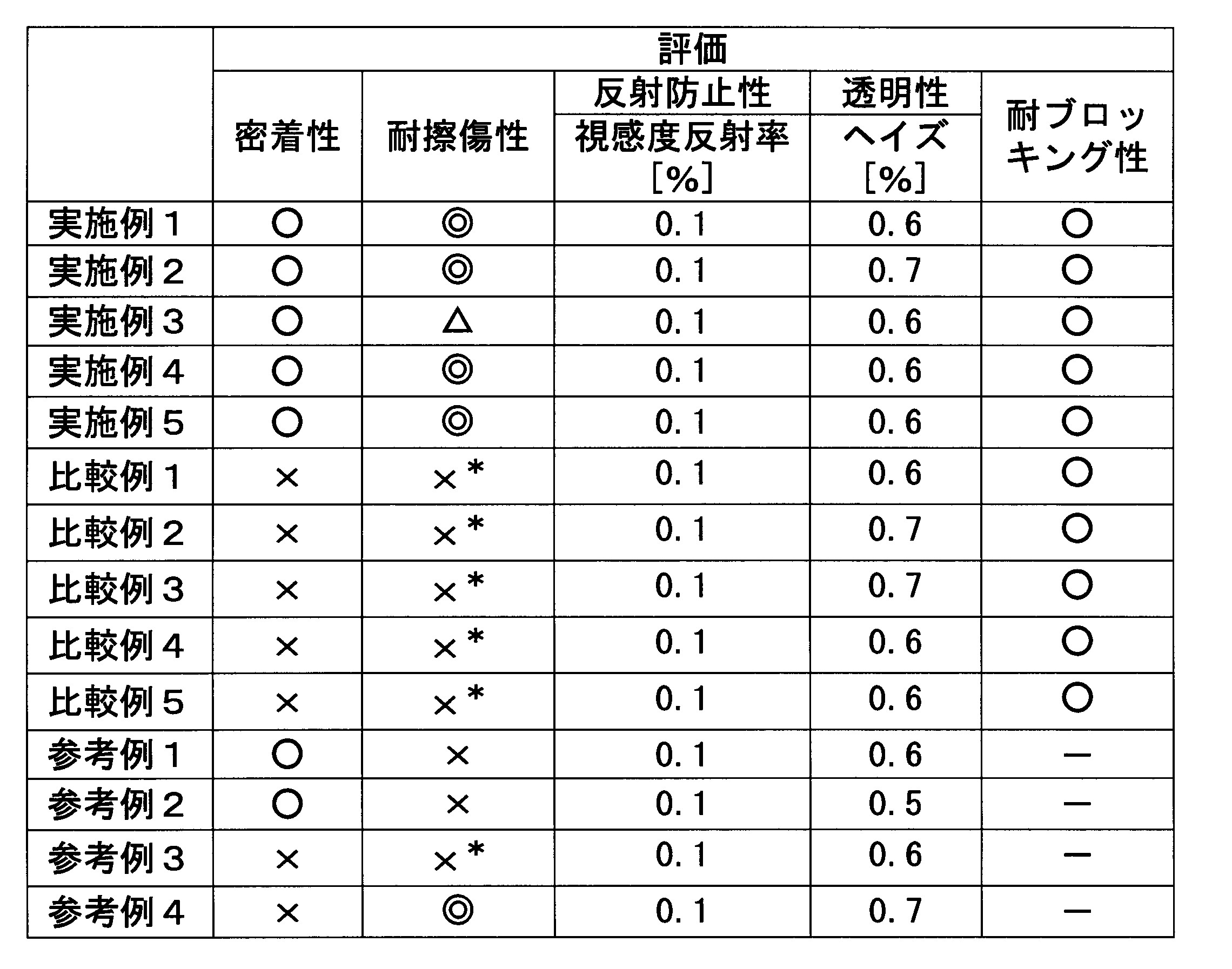
一方、中間層の表面に微細凹凸構造が形成されていない比較例1~5の積層構造体は、各実施例の積層構造体と同程度の反射防止性および透明性を有していたが、中間層と最表層との密着性が劣り、耐擦傷性を評価する磨耗試験時に最表層に剥がれが発生した。
また、参考例1、2から明らかなように、基材への密着性に優れた樹脂組成物Aは耐擦傷性が劣り、参考例4から明らかなように、耐擦傷性が良好な樹脂組成物Cは基材への密着性に劣っていた。
これらの結果より、本発明によれば、2層以上の表面に特定の微細凹凸構造を有することで、密着性と耐擦傷性の両立が可能であることが示された。
10’ 積層体
12 基材
14 中間層
14a 表面に微細凹凸構造を有する層
14b 表面に微細凹凸構造を有さない層
16 最表層
20 アルミニウム基材
22 細孔
24 酸化皮膜
26 細孔発生点
28 モールド
30 ロール状モールド
32 タンク
34 空気圧シリンダ
36 ニップロール
38 活性エネルギー線照射装置
40 剥離ロール
Claims (17)
- 2つ以上の層が積層された積層構造体であって、
少なくとも2つの層の表面に微細凹凸構造を有し、かつ任意の層の微細凹凸構造の凹部および凸部が、他の少なくとも1つの層の微細凹凸構造の凹部および凸部と異なって配置され、
界面が離型処理されていない、積層構造体。 - 任意の層の微細凹凸構造の凹部間または凸部間の平均間隔が、他の少なくとも1つの層の微細凹凸構造の凹部間または凸部間の平均間隔と異なる、請求項1に記載の積層構造体。
- 少なくとも最表層の表面に前記微細凹凸構造を有する、請求項1または2に記載の積層構造体。
- 最表層の微細凹凸構造の凹部間または凸部間の平均間隔が、他の少なくとも1つの層の微細凹凸構造の凹部間または凸部間の平均間隔よりも大きい、請求項3に記載の積層構造体。
- 2つ以上の層が積層された積層構造体であって、
最表層は表面に微細凹凸構造を有さない層であり、
最表層以外の少なくとも1つの層の表面に微細凹凸構造を有する、積層構造体。 - 最表層が、表面に微細凹凸構造を有さないコーティング層である、請求項1または5に記載の積層構造体。
- 最表層の弾性回復率が70%以上である、請求項1~6のいずれか一項に記載の積層構造体。
- 最表層の弾性率が80MPa以上である、請求項1~7のいずれか一項に記載の積層構造体。
- 前記微細凹凸構造を表面に有する層が、活性エネルギー線硬化性樹脂組成物の硬化物からなる層である、請求項1~8のいずれか一項に記載の積層構造体。
- 前記活性エネルギー線硬化性樹脂組成物が(メタ)アクリレート類を含む、請求項9に記載の積層構造体。
- JIS K 5600-5-6:1999(ISO 2409:1992)に準じたクロスカットテープ剥離試験において、2.0mm間隔で碁盤目状の切れ込みを100マス形成し、この切れ込みに粘着テープを貼着した後、剥離したときに剥がれる切れ込みの数が100マスのうち50マス未満である、請求項1~10のいずれか一項に記載の積層構造体。
- 請求項1~11のいずれか一項に記載の積層構造体を表面に備えた、物品。
- 請求項1~11のいずれか一項に記載の積層構造体の製造方法であって、
モールドを用いた転写法により前記微細凹凸構造を形成する、積層構造体の製造方法。 - 請求項1~4のいずれか一項に記載の積層構造体の製造方法であって、
下記工程(1-1)、(1-2)を含む、積層構造体の製造方法。
(1-1)基材上に中間層用の活性エネルギー線硬化性樹脂組成物を供給し、微細凹凸構造を表面に有するモールドを用いて微細凹凸構造を転写し、次いで微細凹凸構造を転写した中間層用の活性エネルギー線硬化性樹脂組成物を活性エネルギー線の照射により硬化して中間層を形成した後に、中間層とモールドを剥離する工程。
(1-2)工程(1-1)を1回以上繰り返した後、得られた中間層の表面に最表層用の活性エネルギー線硬化性樹脂組成物を供給し、微細凹凸構造を表面に有するモールドを用いて微細凹凸構造を転写し、次いで微細凹凸構造を転写した最表層用の活性エネルギー線硬化性樹脂組成物を活性エネルギー線の照射により硬化して最表層を形成した後に、最表層とモールドを剥離する工程。 - 請求項1~4のいずれか一項に記載の積層構造体の製造方法であって、
下記工程(2-1)、(2-2)を含む、積層構造体の製造方法。
(2-1)微細凹凸構造を表面に有するモールドの該表面上に最表層用の活性エネルギー線硬化性樹脂組成物を供給し、モールドの微細凹凸構造を転写する工程。
(2-2)モールド上の最表層用の活性エネルギー線硬化性樹脂組成物上に、微細凹凸構造を表面に有する中間層が積層した基材を中間層側が接するように配置し、次いで微細凹凸構造を転写した最表層用の活性エネルギー線硬化性樹脂組成物を活性エネルギー線の照射により硬化して最表層を形成した後に、最表層とモールドを剥離する工程。 - 請求項1~4のいずれか一項に記載の積層構造体の製造方法であって、
下記工程(3-1)、(3-2)を含む、積層構造体の製造方法。
(3-1)微細凹凸構造を表面に有するモールドの該表面上に最表層用の活性エネルギー線硬化性樹脂組成物を供給し、モールドの微細凹凸構造を転写し、次いで微細凹凸構造を転写した最表層用の活性エネルギー線硬化性樹脂組成物を活性エネルギー線の照射により半硬化する工程。
(3-2)モールド上の半硬化した最表層用の活性エネルギー線硬化性樹脂組成物上に、微細凹凸構造を表面に有する中間層が積層した基材を中間層側が接するように配置し、次いで半硬化した最表層用の活性エネルギー線硬化性樹脂組成物を活性エネルギー線の照射により硬化して最表層を形成した後に、最表層とモールドを剥離する工程。 - 請求項5に記載の積層構造体の製造方法であって、
下記工程(4-1)、(4-2)を含む積層構造体の製造方法。
(4-1)基材上に中間層用の活性エネルギー線硬化性樹脂組成物を供給し、微細凹凸構造を表面に有するモールドを用いて微細凹凸構造を転写し、次いで微細凹凸構造を転写した中間層用の活性エネルギー線硬化性樹脂組成物を活性エネルギー線の照射により硬化して中間層を形成した後に、中間層とモールドを剥離する工程。
(4-2)工程(4-1)を1回以上繰り返した後、得られた中間層の表面に最表層を形成する工程。
Priority Applications (4)
| Application Number | Priority Date | Filing Date | Title |
|---|---|---|---|
| US14/432,824 US20150231854A1 (en) | 2012-10-22 | 2013-10-11 | Layered structure and method for manufacturing same, and article |
| JP2013549627A JPWO2014065136A1 (ja) | 2012-10-22 | 2013-10-11 | 積層構造体およびその製造方法と、物品 |
| CN201380055272.5A CN104755259A (zh) | 2012-10-22 | 2013-10-11 | 层积结构体以及其制造方法、制品 |
| KR1020157008382A KR20150052202A (ko) | 2012-10-22 | 2013-10-11 | 적층 구조체 및 그 제조 방법과 물품 |
Applications Claiming Priority (2)
| Application Number | Priority Date | Filing Date | Title |
|---|---|---|---|
| JP2012232808 | 2012-10-22 | ||
| JP2012-232808 | 2012-10-22 |
Publications (1)
| Publication Number | Publication Date |
|---|---|
| WO2014065136A1 true WO2014065136A1 (ja) | 2014-05-01 |
Family
ID=50544516
Family Applications (1)
| Application Number | Title | Priority Date | Filing Date |
|---|---|---|---|
| PCT/JP2013/077776 Ceased WO2014065136A1 (ja) | 2012-10-22 | 2013-10-11 | 積層構造体およびその製造方法と、物品 |
Country Status (6)
| Country | Link |
|---|---|
| US (1) | US20150231854A1 (ja) |
| JP (1) | JPWO2014065136A1 (ja) |
| KR (1) | KR20150052202A (ja) |
| CN (1) | CN104755259A (ja) |
| TW (1) | TW201422439A (ja) |
| WO (1) | WO2014065136A1 (ja) |
Cited By (15)
| Publication number | Priority date | Publication date | Assignee | Title |
|---|---|---|---|---|
| WO2014163198A1 (ja) * | 2013-04-05 | 2014-10-09 | 三菱レイヨン株式会社 | 積層構造体およびその製造方法と、物品 |
| WO2015170465A1 (en) * | 2014-05-09 | 2015-11-12 | Canon Kabushiki Kaisha | Curable composition and cured product thereof, method for producing cured product, method for manufacturing optical component, method for manufacturing circuit board, and method for manufacturing electronic component |
| JP2016004259A (ja) * | 2014-06-19 | 2016-01-12 | デクセリアルズ株式会社 | 光学フィルム及びその製造方法 |
| WO2016103980A1 (ja) * | 2014-12-25 | 2016-06-30 | デクセリアルズ株式会社 | 光学体、光学フィルム貼着体及び光学体の製造方法 |
| WO2017110697A1 (ja) * | 2015-12-22 | 2017-06-29 | 日産化学工業株式会社 | インプリント材料 |
| EP3165358A4 (en) * | 2014-07-23 | 2018-03-07 | Dexerials Corporation | Transparent film for face protective shield |
| JP2018079617A (ja) * | 2016-11-16 | 2018-05-24 | リケンテクノス株式会社 | 表面に微細凹凸構造を有する塗膜 |
| JP2018149807A (ja) * | 2017-03-13 | 2018-09-27 | 三菱ケミカル株式会社 | 金型離型処理溶液及びフィルムの製造方法 |
| EP3299852A4 (en) * | 2015-05-21 | 2018-10-24 | Dexerials Corporation | Transparent laminate |
| WO2019009199A1 (ja) * | 2017-07-03 | 2019-01-10 | デクセリアルズ株式会社 | 微細凹凸積層体及びその製造方法、並びに、カメラモジュール搭載装置 |
| WO2019009200A1 (ja) * | 2017-07-03 | 2019-01-10 | デクセリアルズ株式会社 | 積層体、光学体の形成方法、及び、カメラモジュール搭載装置 |
| KR102060872B1 (ko) | 2015-04-30 | 2019-12-30 | 샤프 가부시키가이샤 | 광학 필름의 제조 방법 및 광학 필름 |
| WO2020095792A1 (ja) * | 2018-11-08 | 2020-05-14 | デクセリアルズ株式会社 | 積層体、積層体の製造方法、光学体の形成方法及びカメラモジュール搭載装置 |
| CN111971590A (zh) * | 2018-03-30 | 2020-11-20 | 迪睿合株式会社 | 树脂层叠光学体及其制造方法 |
| WO2023228775A1 (ja) * | 2022-05-25 | 2023-11-30 | 北陽電機株式会社 | 反射ミラー部材、光電センサ、および光測距装置 |
Families Citing this family (10)
| Publication number | Priority date | Publication date | Assignee | Title |
|---|---|---|---|---|
| JP5629025B2 (ja) * | 2013-01-23 | 2014-11-19 | デクセリアルズ株式会社 | 親水性積層体、及びその製造方法、防汚用積層体、物品、及びその製造方法、並びに防汚方法 |
| JP6071696B2 (ja) * | 2013-03-27 | 2017-02-01 | デクセリアルズ株式会社 | 親油性積層体、及びその製造方法、並びに物品、及びその製造方法 |
| JP6002172B2 (ja) * | 2014-05-21 | 2016-10-05 | 株式会社東芝 | 表示装置 |
| JP6623058B2 (ja) * | 2015-12-18 | 2019-12-18 | デクセリアルズ株式会社 | 反射防止光学体の形成方法およびディスプレイパネル |
| JP6730803B2 (ja) * | 2015-12-18 | 2020-07-29 | デクセリアルズ株式会社 | 反射防止光学体の形成方法、ディスプレイパネルおよび光学フィルム |
| KR102506441B1 (ko) * | 2017-12-04 | 2023-03-06 | 삼성전자주식회사 | 반도체 발광 어레이의 제조 방법 및 반도체 발광 어레이 |
| JP6445747B1 (ja) * | 2018-03-30 | 2018-12-26 | リンテック株式会社 | 保護膜形成用複合シート |
| JP7103186B2 (ja) * | 2018-11-22 | 2022-07-20 | マツダ株式会社 | 樹脂製部材、樹脂製部材の成形用金型及び樹脂製部材の製造方法 |
| JP7251167B2 (ja) * | 2019-01-28 | 2023-04-04 | 株式会社レゾナック | フィルム状接着剤、接着シート、並びに半導体装置及びその製造方法 |
| JP7743142B2 (ja) * | 2022-01-20 | 2025-09-24 | パナソニックオートモーティブシステムズ株式会社 | 接着方法 |
Citations (7)
| Publication number | Priority date | Publication date | Assignee | Title |
|---|---|---|---|---|
| JP2005521894A (ja) * | 2002-04-03 | 2005-07-21 | ドゥ ラ リュ インターナショナル リミティド | 光学的に可変のセキュリティ・デバイス及び方法 |
| JP2009150998A (ja) * | 2007-12-19 | 2009-07-09 | Sumitomo Chemical Co Ltd | 防眩フィルム、防眩性偏光板および画像表示装置 |
| JP2009300870A (ja) * | 2008-06-16 | 2009-12-24 | Mitsubishi Rayon Co Ltd | 光拡散フィルムおよびプリズムシート |
| JP2010201641A (ja) * | 2009-02-27 | 2010-09-16 | Mitsubishi Rayon Co Ltd | 微細凹凸構造を表面に有する透明フィルムおよびその製造方法 |
| JP2011033892A (ja) * | 2009-08-03 | 2011-02-17 | Dainippon Printing Co Ltd | 反射防止フィルム、偏光板、および表示装置 |
| JP2011054443A (ja) * | 2009-09-02 | 2011-03-17 | Sharp Corp | 拡散材、導光体ユニット、および面光源装置 |
| JP2011070116A (ja) * | 2009-09-28 | 2011-04-07 | Dainippon Printing Co Ltd | 反射防止フィルム製造用組成物、反射防止フィルム、反射防止フィルムの製造方法、偏光板、および液晶表示装置 |
-
2013
- 2013-10-11 US US14/432,824 patent/US20150231854A1/en not_active Abandoned
- 2013-10-11 WO PCT/JP2013/077776 patent/WO2014065136A1/ja not_active Ceased
- 2013-10-11 KR KR1020157008382A patent/KR20150052202A/ko not_active Withdrawn
- 2013-10-11 CN CN201380055272.5A patent/CN104755259A/zh active Pending
- 2013-10-11 JP JP2013549627A patent/JPWO2014065136A1/ja active Pending
- 2013-10-18 TW TW102137598A patent/TW201422439A/zh unknown
Patent Citations (7)
| Publication number | Priority date | Publication date | Assignee | Title |
|---|---|---|---|---|
| JP2005521894A (ja) * | 2002-04-03 | 2005-07-21 | ドゥ ラ リュ インターナショナル リミティド | 光学的に可変のセキュリティ・デバイス及び方法 |
| JP2009150998A (ja) * | 2007-12-19 | 2009-07-09 | Sumitomo Chemical Co Ltd | 防眩フィルム、防眩性偏光板および画像表示装置 |
| JP2009300870A (ja) * | 2008-06-16 | 2009-12-24 | Mitsubishi Rayon Co Ltd | 光拡散フィルムおよびプリズムシート |
| JP2010201641A (ja) * | 2009-02-27 | 2010-09-16 | Mitsubishi Rayon Co Ltd | 微細凹凸構造を表面に有する透明フィルムおよびその製造方法 |
| JP2011033892A (ja) * | 2009-08-03 | 2011-02-17 | Dainippon Printing Co Ltd | 反射防止フィルム、偏光板、および表示装置 |
| JP2011054443A (ja) * | 2009-09-02 | 2011-03-17 | Sharp Corp | 拡散材、導光体ユニット、および面光源装置 |
| JP2011070116A (ja) * | 2009-09-28 | 2011-04-07 | Dainippon Printing Co Ltd | 反射防止フィルム製造用組成物、反射防止フィルム、反射防止フィルムの製造方法、偏光板、および液晶表示装置 |
Cited By (46)
| Publication number | Priority date | Publication date | Assignee | Title |
|---|---|---|---|---|
| JP5716868B2 (ja) * | 2013-04-05 | 2015-05-13 | 三菱レイヨン株式会社 | 積層構造体およびその製造方法と、物品 |
| WO2014163198A1 (ja) * | 2013-04-05 | 2014-10-09 | 三菱レイヨン株式会社 | 積層構造体およびその製造方法と、物品 |
| KR20180137046A (ko) * | 2014-05-09 | 2018-12-26 | 캐논 가부시끼가이샤 | 경화성 조성물 및 그의 경화물, 경화물의 제조 방법, 광학 부품의 제조 방법, 회로 기판의 제조 방법, 및 전자 부품의 제조 방법 |
| WO2015170465A1 (en) * | 2014-05-09 | 2015-11-12 | Canon Kabushiki Kaisha | Curable composition and cured product thereof, method for producing cured product, method for manufacturing optical component, method for manufacturing circuit board, and method for manufacturing electronic component |
| KR101932331B1 (ko) | 2014-05-09 | 2018-12-24 | 캐논 가부시끼가이샤 | 경화성 조성물 및 그의 경화물, 경화물의 제조 방법, 광학 부품의 제조 방법, 회로 기판의 제조 방법, 및 전자 부품의 제조 방법 |
| JP2016029138A (ja) * | 2014-05-09 | 2016-03-03 | キヤノン株式会社 | 硬化性組成物、その硬化物、硬化物の製造方法、光学部品の製造方法、回路基板の製造方法、および電子部品の製造方法 |
| KR102045700B1 (ko) | 2014-05-09 | 2019-11-15 | 캐논 가부시끼가이샤 | 경화성 조성물 및 그의 경화물, 경화물의 제조 방법, 광학 부품의 제조 방법, 회로 기판의 제조 방법, 및 전자 부품의 제조 방법 |
| US10023673B2 (en) | 2014-05-09 | 2018-07-17 | Canon Kabushiki Kaisha | Curable composition and cured product thereof, method for producing cured product, method for manufacturing optical component, method for manufacturing circuit board, and method for manufacturing electronic component |
| TWI567493B (zh) * | 2014-05-09 | 2017-01-21 | 佳能股份有限公司 | 可固化組成物及其固化產物,製造固化產物的方法,製造光學組件的方法,製造電路板的方法,以及製造電子組件的方法 |
| JP2016004259A (ja) * | 2014-06-19 | 2016-01-12 | デクセリアルズ株式会社 | 光学フィルム及びその製造方法 |
| US11693156B2 (en) | 2014-06-19 | 2023-07-04 | Dexerials Corporation | Optical body, film adhesive body, and method for manufacturing optical body |
| EP3165358A4 (en) * | 2014-07-23 | 2018-03-07 | Dexerials Corporation | Transparent film for face protective shield |
| US10575572B2 (en) | 2014-07-23 | 2020-03-03 | Dexerials Corporation | Transparent film for face protection shield |
| WO2016103980A1 (ja) * | 2014-12-25 | 2016-06-30 | デクセリアルズ株式会社 | 光学体、光学フィルム貼着体及び光学体の製造方法 |
| US12502864B2 (en) | 2014-12-25 | 2025-12-23 | Dexerials Corporation | Optical body, optical film adhesive body, and method for manufacturing optical body |
| CN107111002A (zh) * | 2014-12-25 | 2017-08-29 | 迪睿合株式会社 | 光学体、光学膜粘合体及光学体的制造方法 |
| CN107111002B (zh) * | 2014-12-25 | 2020-04-14 | 迪睿合株式会社 | 光学体、光学膜粘合体及光学体的制造方法 |
| JP2016122163A (ja) * | 2014-12-25 | 2016-07-07 | デクセリアルズ株式会社 | 光学フィルム及びその製造方法 |
| KR102060872B1 (ko) | 2015-04-30 | 2019-12-30 | 샤프 가부시키가이샤 | 광학 필름의 제조 방법 및 광학 필름 |
| EP3299852A4 (en) * | 2015-05-21 | 2018-10-24 | Dexerials Corporation | Transparent laminate |
| EP3882673A1 (en) * | 2015-05-21 | 2021-09-22 | Dexerials Corporation | Transparent laminate |
| JPWO2017110697A1 (ja) * | 2015-12-22 | 2018-10-11 | 日産化学株式会社 | インプリント材料 |
| WO2017110697A1 (ja) * | 2015-12-22 | 2017-06-29 | 日産化学工業株式会社 | インプリント材料 |
| JP2018079617A (ja) * | 2016-11-16 | 2018-05-24 | リケンテクノス株式会社 | 表面に微細凹凸構造を有する塗膜 |
| JP2018149807A (ja) * | 2017-03-13 | 2018-09-27 | 三菱ケミカル株式会社 | 金型離型処理溶液及びフィルムの製造方法 |
| JP7087461B2 (ja) | 2017-03-13 | 2022-06-21 | 三菱ケミカル株式会社 | 金型離型処理溶液及びフィルムの製造方法 |
| WO2019009199A1 (ja) * | 2017-07-03 | 2019-01-10 | デクセリアルズ株式会社 | 微細凹凸積層体及びその製造方法、並びに、カメラモジュール搭載装置 |
| JP2019014247A (ja) * | 2017-07-03 | 2019-01-31 | デクセリアルズ株式会社 | 積層体、光学体の形成方法、及び、カメラモジュール搭載装置 |
| JP7499556B2 (ja) | 2017-07-03 | 2024-06-14 | デクセリアルズ株式会社 | 微細凹凸積層体及びその製造方法、並びに、カメラモジュール搭載装置 |
| JP7545528B2 (ja) | 2017-07-03 | 2024-09-04 | デクセリアルズ株式会社 | 微細凹凸積層体及びその製造方法、並びに、カメラモジュール搭載装置 |
| WO2019009200A1 (ja) * | 2017-07-03 | 2019-01-10 | デクセリアルズ株式会社 | 積層体、光学体の形成方法、及び、カメラモジュール搭載装置 |
| JP2023118748A (ja) * | 2017-07-03 | 2023-08-25 | デクセリアルズ株式会社 | 微細凹凸積層体及びその製造方法、並びに、カメラモジュール搭載装置 |
| JP7075838B2 (ja) | 2017-07-03 | 2022-05-26 | デクセリアルズ株式会社 | 積層体、光学体の形成方法、及び、カメラモジュール搭載装置 |
| US12290992B2 (en) | 2017-07-03 | 2025-05-06 | Dexerials Corporation | Laminate, method of forming optical body, and camera module-mounted device |
| JP2019015965A (ja) * | 2017-07-03 | 2019-01-31 | デクセリアルズ株式会社 | 微細凹凸積層体及びその製造方法、並びに、カメラモジュール搭載装置 |
| US11693157B2 (en) | 2017-07-03 | 2023-07-04 | Dexerials Corporation | Fine concave-convex laminate and production method therefor, and camera module-mounted device |
| US11897182B2 (en) | 2018-03-30 | 2024-02-13 | Dexerials Corporation | Resin laminated optical body and method for manufacturing the same |
| CN111971590B (zh) * | 2018-03-30 | 2023-03-10 | 迪睿合株式会社 | 树脂层叠光学体及其制造方法 |
| EP3757627A4 (en) * | 2018-03-30 | 2021-11-03 | Dexerials Corporation | RESIN STACKED OPTICAL BODY AND METHOD OF MANUFACTURING THEREOF |
| CN111971590A (zh) * | 2018-03-30 | 2020-11-20 | 迪睿合株式会社 | 树脂层叠光学体及其制造方法 |
| JP7208765B2 (ja) | 2018-11-08 | 2023-01-19 | デクセリアルズ株式会社 | 積層体、積層体の製造方法、光学体の形成方法及びカメラモジュール搭載装置 |
| CN112912240A (zh) * | 2018-11-08 | 2021-06-04 | 迪睿合株式会社 | 层叠体、层叠体的制造方法、光学体的形成方法和相机模块搭载装置 |
| JP2020075430A (ja) * | 2018-11-08 | 2020-05-21 | デクセリアルズ株式会社 | 積層体、積層体の製造方法、光学体の形成方法及びカメラモジュール搭載装置 |
| US12399303B2 (en) | 2018-11-08 | 2025-08-26 | Dexerials Corporation | Laminate, method of producing laminate, method of forming optical body, and camera module-equipped device |
| WO2020095792A1 (ja) * | 2018-11-08 | 2020-05-14 | デクセリアルズ株式会社 | 積層体、積層体の製造方法、光学体の形成方法及びカメラモジュール搭載装置 |
| WO2023228775A1 (ja) * | 2022-05-25 | 2023-11-30 | 北陽電機株式会社 | 反射ミラー部材、光電センサ、および光測距装置 |
Also Published As
| Publication number | Publication date |
|---|---|
| US20150231854A1 (en) | 2015-08-20 |
| CN104755259A (zh) | 2015-07-01 |
| TW201422439A (zh) | 2014-06-16 |
| JPWO2014065136A1 (ja) | 2016-09-08 |
| KR20150052202A (ko) | 2015-05-13 |
Similar Documents
| Publication | Publication Date | Title |
|---|---|---|
| JPWO2014065136A1 (ja) | 積層構造体およびその製造方法と、物品 | |
| JP6451321B2 (ja) | 光学物品及びその製造方法 | |
| JP5716868B2 (ja) | 積層構造体およびその製造方法と、物品 | |
| JP4990414B2 (ja) | 微細凹凸構造を表面に有する物品の製造方法、金型の離型処理方法、および金型表面離型処理用活性エネルギー線硬化性樹脂組成物 | |
| JP5742220B2 (ja) | フィルムの製造方法 | |
| JP2015054402A (ja) | 積層構造体およびその製造方法、反射防止物品 | |
| JP5958338B2 (ja) | 微細凹凸構造体、撥水性物品、モールド、及び微細凹凸構造体の製造方法 | |
| JP5605223B2 (ja) | 反射防止物品およびディスプレイ装置 | |
| JP6052164B2 (ja) | 積層構造体 | |
| JP6686284B2 (ja) | 活性エネルギー線硬化性樹脂組成物の硬化物を含む物品 | |
| JP2011026449A (ja) | 積層体、およびこれを有する物品 | |
| JP2014005341A (ja) | 微細凹凸構造を表面に有する物品 | |
| JP2016210150A (ja) | 積層体およびその製造方法と、物品 | |
| JP2009271205A (ja) | 光学ミラー | |
| JPWO2016158979A1 (ja) | 活性エネルギー線硬化性樹脂組成物及び物品 | |
| JP2011245767A (ja) | 積層体、およびこれを有する物品 | |
| JP2017160295A (ja) | 活性エネルギー線硬化性樹脂組成物、インプリント用原料、および成形品 | |
| JP2015223725A (ja) | 微細凹凸構造を表面に有する物品の製造方法 | |
| JP2015074200A (ja) | 光透過性意匠部材および物品 | |
| JP2013215918A (ja) | 積層体、およびこれを有する物品 |
Legal Events
| Date | Code | Title | Description |
|---|---|---|---|
| ENP | Entry into the national phase |
Ref document number: 2013549627 Country of ref document: JP Kind code of ref document: A |
|
| 121 | Ep: the epo has been informed by wipo that ep was designated in this application |
Ref document number: 13848694 Country of ref document: EP Kind code of ref document: A1 |
|
| ENP | Entry into the national phase |
Ref document number: 20157008382 Country of ref document: KR Kind code of ref document: A |
|
| WWE | Wipo information: entry into national phase |
Ref document number: 14432824 Country of ref document: US |
|
| NENP | Non-entry into the national phase |
Ref country code: DE |
|
| 122 | Ep: pct application non-entry in european phase |
Ref document number: 13848694 Country of ref document: EP Kind code of ref document: A1 |