WO2014010502A1 - レーダ装置 - Google Patents
レーダ装置 Download PDFInfo
- Publication number
- WO2014010502A1 WO2014010502A1 PCT/JP2013/068344 JP2013068344W WO2014010502A1 WO 2014010502 A1 WO2014010502 A1 WO 2014010502A1 JP 2013068344 W JP2013068344 W JP 2013068344W WO 2014010502 A1 WO2014010502 A1 WO 2014010502A1
- Authority
- WO
- WIPO (PCT)
- Prior art keywords
- wall
- radar
- wall body
- radome
- antenna
- Prior art date
- Legal status (The legal status is an assumption and is not a legal conclusion. Google has not performed a legal analysis and makes no representation as to the accuracy of the status listed.)
- Ceased
Links
Images



Classifications
-
- H—ELECTRICITY
- H01—ELECTRIC ELEMENTS
- H01Q—ANTENNAS, i.e. RADIO AERIALS
- H01Q1/00—Details of, or arrangements associated with, antennas
- H01Q1/42—Housings not intimately mechanically associated with radiating elements, e.g. radome
-
- G—PHYSICS
- G01—MEASURING; TESTING
- G01S—RADIO DIRECTION-FINDING; RADIO NAVIGATION; DETERMINING DISTANCE OR VELOCITY BY USE OF RADIO WAVES; LOCATING OR PRESENCE-DETECTING BY USE OF THE REFLECTION OR RERADIATION OF RADIO WAVES; ANALOGOUS ARRANGEMENTS USING OTHER WAVES
- G01S7/00—Details of systems according to groups G01S13/00, G01S15/00, G01S17/00
- G01S7/02—Details of systems according to groups G01S13/00, G01S15/00, G01S17/00 of systems according to group G01S13/00
- G01S7/28—Details of pulse systems
- G01S7/2813—Means providing a modification of the radiation pattern for cancelling noise, clutter or interfering signals, e.g. side lobe suppression, side lobe blanking, null-steering arrays
-
- H—ELECTRICITY
- H01—ELECTRIC ELEMENTS
- H01Q—ANTENNAS, i.e. RADIO AERIALS
- H01Q1/00—Details of, or arrangements associated with, antennas
- H01Q1/27—Adaptation for use in or on movable bodies
- H01Q1/32—Adaptation for use in or on road or rail vehicles
- H01Q1/3208—Adaptation for use in or on road or rail vehicles characterised by the application wherein the antenna is used
- H01Q1/3233—Adaptation for use in or on road or rail vehicles characterised by the application wherein the antenna is used particular used as part of a sensor or in a security system, e.g. for automotive radar, navigation systems
-
- H—ELECTRICITY
- H01—ELECTRIC ELEMENTS
- H01Q—ANTENNAS, i.e. RADIO AERIALS
- H01Q1/00—Details of, or arrangements associated with, antennas
- H01Q1/42—Housings not intimately mechanically associated with radiating elements, e.g. radome
- H01Q1/421—Means for correcting aberrations introduced by a radome
-
- G—PHYSICS
- G01—MEASURING; TESTING
- G01S—RADIO DIRECTION-FINDING; RADIO NAVIGATION; DETERMINING DISTANCE OR VELOCITY BY USE OF RADIO WAVES; LOCATING OR PRESENCE-DETECTING BY USE OF THE REFLECTION OR RERADIATION OF RADIO WAVES; ANALOGOUS ARRANGEMENTS USING OTHER WAVES
- G01S13/00—Systems using the reflection or reradiation of radio waves, e.g. radar systems; Analogous systems using reflection or reradiation of waves whose nature or wavelength is irrelevant or unspecified
- G01S13/88—Radar or analogous systems specially adapted for specific applications
- G01S13/93—Radar or analogous systems specially adapted for specific applications for anti-collision purposes
- G01S13/931—Radar or analogous systems specially adapted for specific applications for anti-collision purposes of land vehicles
-
- G—PHYSICS
- G01—MEASURING; TESTING
- G01S—RADIO DIRECTION-FINDING; RADIO NAVIGATION; DETERMINING DISTANCE OR VELOCITY BY USE OF RADIO WAVES; LOCATING OR PRESENCE-DETECTING BY USE OF THE REFLECTION OR RERADIATION OF RADIO WAVES; ANALOGOUS ARRANGEMENTS USING OTHER WAVES
- G01S7/00—Details of systems according to groups G01S13/00, G01S15/00, G01S17/00
- G01S7/02—Details of systems according to groups G01S13/00, G01S15/00, G01S17/00 of systems according to group G01S13/00
- G01S7/027—Constructional details of housings, e.g. form, type, material or ruggedness
Definitions
- the present invention relates to a radar apparatus including an antenna and a radome that protects the antenna.
- the radar device is a device that detects a distance, a direction, and the like with an obstacle existing around by transmitting a radio wave and receiving a reflected wave of the transmitted radio wave.
- the antenna provided in the radar apparatus is protected by a radome.
- Patent Document 1 a radome having an attenuation radome portion is known (see Patent Document 1).
- the attenuation radome described in Patent Document 1 has a core layer formed of a material that gives high loss to a radio wave transmitted and received by an antenna (hereinafter referred to as a radar wave), and a direction through the attenuation radome Reduce the emission of radio waves.
- the attenuation radome described in Patent Document 1 has a radio wave attenuation rate that increases in proportion to the thickness of the core layer. Therefore, it is necessary to sufficiently attenuate radio wave radiation in order to achieve desired directivity. In such a case, there is a problem that the core layer must be formed thick. That is, there is a possibility that downsizing of the apparatus may be hindered.
- the present invention has been made in view of these problems, and it would be desirable to be able to provide a radar apparatus capable of realizing desired directivity without hindering downsizing of the apparatus.
- a radar apparatus includes an antenna that performs at least one of transmission and reception of a radar wave, a radome that transmits the radar wave, and a wall portion.
- the wall portion is provided on the surface (opposing surface) of the radome facing the antenna.
- the wall portion protrudes from the facing surface toward the space formed by the radome, and at least a part of the outer periphery of the opening projection portion that projects the antenna opening surface on the facing surface in the normal direction of the antenna opening surface. It is formed along.
- the wall portion may be formed intermittently along the outer periphery of the aperture projection portion, or may be formed so as to surround the outer periphery of the aperture projection portion depending on the mode. Or the said wall part may be provided only in the direction which suppresses a radar wave.
- the value of the side lobe formed in the direction deviating from the normal direction of the antenna opening surface in the directivity pattern formed by the antenna can be reduced by the wall portion. Further, since the wall portion is provided inside the radome, it does not affect the outer shape (size) of the radar apparatus. Therefore, desired directivity can be realized without hindering downsizing of the apparatus.
- the wall portion may be configured to include a plurality of wall bodies arranged at intervals in a direction from the aperture projection portion toward the outside of the aperture projection portion, depending on an aspect. it can. By providing a plurality of wall bodies, it is possible to increase the attenuation by the wall portion.
- At least one of the walls is 2n ⁇ 1 times (where n is a natural number) a quarter of the wavelength of the radar wave in the wall. It can comprise so that it may consist of a 1st wall body which has thickness.
- a radar apparatus for example, when a radar wave is transmitted from an antenna through a radome, a transmission wave that passes through the first wall body as it is and a first wave body that passes through the first wall body after multiple reflection at the first wall body.
- the transmission wave has a path difference that is an integral multiple of one half of the wavelength of the radar wave in the first wall, and is out of phase by one-half wavelength. For this reason, both transmission waves act so as to cancel each other.
- the radar wave transmitted through the wall portion made of the first wall body can be efficiently attenuated.
- the attenuation effect of a radar wave can be improved more.
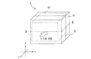
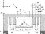
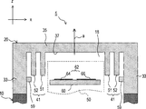
- FIG. 1 is a perspective view showing a radar apparatus according to a first embodiment of the present invention. It is sectional drawing of the said radar apparatus in the II-II line
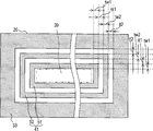
- FIG. 3 is a cross-sectional view of the radar apparatus taken along line III-III in FIG. 2. It is explanatory drawing which shows an example of the path
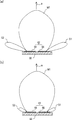
- (A) is explanatory drawing which shows the synthetic directivity of an antenna part
- (b) is explanatory drawing which shows the synthetic directivity of the antenna part changed by having provided the wall part. It is explanatory drawing which shows the structure of the radar apparatus of 2nd embodiment of this invention.
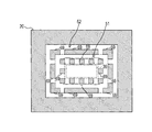
- (A) to (d) is an explanatory view showing a state in which a radome of a radar apparatus according to another embodiment described in (v) is viewed from the main body side. It is explanatory drawing which shows the structure of the wall part and 3rd wall body of the radar apparatus of other embodiment described in (vi).
- a radar apparatus 1 according to the first embodiment shown in FIG. 1 is mounted on a vehicle, transmits a radio wave having a predetermined frequency f0 (hereinafter referred to as a radar wave), and receives a reflected wave of a radar wave from a target. By doing so, the target existing around the vehicle is recognized.
- a radar wave a radio wave having a predetermined frequency f0
- the radar device 1 includes a circuit board on which an antenna is formed, and transmits and receives radar waves to recognize a target existing around the vehicle, a main body 10 that houses the radar unit 50, and a main body 10. And a radome 20 that protects the circuit board 60 of the radar unit 50 housed in the main body 10.
- the circuit board 60 is formed on one surface with a transmission antenna unit 64 that transmits a radar wave and a reception antenna unit 66 that receives a reflected wave from a target that reflects the radar wave. .
- the circuit board 60 is disposed such that the surface on which both antenna portions 64 and 66 are formed (hereinafter referred to as “antenna formation surface”) is exposed to the radome 20 side at the opening of the main body 10.
- antenna unit 62 when the antenna units 64 and 66 are not identified, both are collectively referred to as the antenna unit 62.
- the antenna unit 62 has a performance (combined directivity) obtained by combining the directivity of the transmission antenna unit 64 and the directivity of the reception antenna unit 66.
- This combined directivity extends in a normal direction (in the direction of arrow a in FIG. 2) with respect to a region where both antenna portions 64 and 66 are formed (hereinafter referred to as “antenna opening surface”), and the normal direction a It has a symmetrical shape.
- the normal direction a is referred to as the beam direction a of the antenna unit 62.
- the beam direction a corresponds to the direction of the z coordinate shown in FIG.
- the radome 20 is formed of a transmission material that is a material that transmits radar waves with low loss.
- the part facing the circuit board 60 in the radome 20, that is, the part located in the beam direction a of the antenna part 62 is the front part 35, and the thickness t1 of the front part 35 is expressed by the following equation (1): It is set to one half of the wavelength of the radar wave propagating through the transmitting material.
- ⁇ 0 is the wavelength of the radar wave propagating in free space
- ⁇ 1 represents the dielectric constant of the transmission material.
- a surface 37 (hereinafter referred to as “opposing surface”) 37 facing the circuit board 60 in the front portion 35 is formed so as to protrude toward a space 18 (hereinafter referred to as “radome space”) 18 formed by the radome 20.
- the wall part 41 which consists of the made first wall bodies 51 and 52 is provided.
- the first wall bodies 51 and 52 are formed of the same transmissive material as the radome 20 and surround the outer periphery of a portion 39 (hereinafter referred to as “opening projection portion”) 39 in which the antenna opening surface is projected on the opposing surface 37 in the normal direction a. (See FIGS. 2 and 3).
- the first wall bodies 51 and 52 are arranged at a predetermined interval tt1 in a direction from the opening projection unit 39 to the outside of the opening projection unit 39.
- ⁇ 2 represents the dielectric constant in the radome space 18. Further, the first wall body 52 is arranged such that the distance tt2 between the radome 20 and the side wall 33 is the same value as the distance tt1.
- the amount of projection (height) of the first wall bodies 51 and 52 from the facing surface 37 is desirably set so that the tip portions of the first wall bodies 51 and 52 are as close as possible to the antenna formation surface of the circuit board 60.
- the first wall bodies 51 and 52 are formed at the same height, and the height P is such that the distance P between the tip portion and the antenna forming surface (see FIG. 2) propagates through the radome space 18.
- the value is set to be equal to or less than a quarter value of the wavelength of the radar wave to be transmitted.
- the operation of the wall 41 will be described by taking as an example a case where a radar wave is transmitted from the antenna 62 through the radome 20 to the outside of the radar apparatus 1.
- a radar wave is transmitted from the antenna 62 through the radome 20 to the outside of the radar apparatus 1.
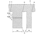
- the space between the first wall bodies 51 and 52 is referred to as a first air layer 82.
- a space between the first wall body 52 and the side wall 33 of the radome 20 is referred to as a second air layer 84.
- a path that enters the first wall body 51 and exits from the first wall body 51 without being reflected in the first wall body is referred to as a first path 71.
- a path that is emitted, that is, a path that is multiple-reflected by the first wall body 51 is referred to as a second path 72.
- a path that is emitted to the first air layer 82 and is incident on the first wall body 52 without being reflected by the first air layer 82 is referred to as a third path 73.
- the first wall body A path that is incident on 52, that is, a path that is multiple-reflected by the first air layer 82 is a fourth path 74.
- a path difference having a value half that of the wavelength of the radar wave at the first wall 51 is generated. That is, since these radar waves are out of phase by a half wavelength, they act so as to cancel each other.
- the radar waves emitted to the first air layer 82 in the same phase the radar waves incident on the first wall body 52 via the third path 73 and the fourth path 74 also in the first air layer 82.
- a path difference of half the value of the wavelength of the radar wave occurs, and these radar waves act so as to cancel each other.
- the first route 71 to the fourth route 74 have been described by way of example, but in addition to the above, in various routes in which radar waves are transmitted from the antenna unit 62 through the wall portion 41 to the outside of the radar apparatus 1, As described above, when the path difference between the radar waves becomes a half value of the wavelength, or when the path difference becomes an odd multiple of the half of the wavelength, the radar waves act so as to cancel each other.
- the radar apparatus 1 includes the first wall bodies 51 and 52 so that the radar waves transmitted through the first wall bodies 51 and 52 cancel each other due to the path difference. Since the wall 41 is provided, it is possible to attenuate a radar wave in a direction deviating from the beam direction a of the antenna unit 62. Specifically, for example, as shown in FIG. 5A, when the antenna unit 62 has a combined directivity composed of the main lobe M1 and the side lobes S1 and S2, the wall portion 41 is provided so that As shown in b), the side lobes S1 and S2 formed in a direction deviating from the beam direction a of the antenna unit 62 can be suppressed.
- the wall part 41 is provided inside the radome 20, the outer shape (size) of the radar apparatus 1 is not affected. Therefore, desired directivity can be realized without hindering the miniaturization of the radar apparatus 1.
- the wall portion 41 may be configured by setting the interval tt1 to a value t3 in the direction from the opening projection portion 39 to the outside of the opening projection portion 39 and further disposing the first wall body.
- the side lobes S1 and S2 formed in a direction deviating from the beam direction a can be further suppressed.
- the antenna unit Radar waves in a direction deviating from the beam direction a 62 can be efficiently attenuated.
- the wall part 41 is formed with the same material as the material which forms the radome 20, the wall part 41 and the radome 20 can be manufactured in the same process. That is, the manufacturing process can be simplified.
- the radar device 2 according to the second embodiment of the present invention will be described.
- the configuration of the wall portion 43 is not the first wall body unlike the radar apparatus 1 of the first embodiment, but the first wall body 52 and the first wall body. Since 52 is composed of the second wall body 53 having a different thickness, the difference will be mainly described.
- the wall portion 43 includes a first wall body 52 and a second wall body 53 disposed closer to the opening projection unit 39 than the first wall body 52.
- a path of a radar wave transmitted from the antenna unit 62 to the outside through the wall 43 for example, as shown in FIG. 7, a path reflected by the surface of the second wall 53 and returning to the radome space 18 is a fifth path 75. And Further, a path that enters the second wall body 53, is reflected at the boundary between the second wall body 53 and the first air layer 82, and returns to the radome space 18 is a sixth path 76.
- a phase shift corresponding to a half wavelength occurs in the reflected wave by the fifth path 75, and in the reflected wave by the sixth path 76 A phase shift corresponding to one wavelength occurs. That is, the reflected waves generated by the fifth path 75 and the sixth path 76 act so as to cancel each other.
- radar waves transmitted to the outside of the radar device 2 through the second wall 53, the first air layer 82, the first wall 52, and the second air layer 84 are It attenuates in the wall and air layer.
- the radar apparatus 2 by providing the wall portion 43 including the first wall body and the second wall body having different thicknesses, the reflected waves returned to the radome space 18 are canceled out by the path difference. At the same time, the radar wave transmitted to the outside can be attenuated.
- the reflected wave to the radome space 18 caused by providing these wall bodies affects the combined directivity of the antenna unit 62.
- the main lobe M2 may be disturbed (see FIG. 8).
- the reflected wave to the radome space 18 is reduced, and the main lobe M2 is reduced. Can be suppressed.
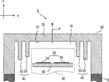
- the heights of the first wall bodies 51 and 52 from the facing surface 37 are set to the same value, but the present invention is not limited to this. Instead, for example, the height of the first wall body 55 located on the side close to the aperture projection section 39 is compared with the height of the first wall body 52, as in the wall section 45 of the radar apparatus 3 shown in FIG. A small value may be set. Thereby, similarly to said 2nd embodiment, the reflected wave to the radome space 18 produced by providing a wall body can be reduced.
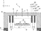
- the first wall bodies 51 and 52 are made of the same material as that forming the radome 20, but the present invention is not limited to this.
- the first wall bodies 57 and 58 are formed of a material that has a dielectric constant different from that of the transmission material forming the radome 20 and transmits radar waves with high loss.
- the wall 47 may be constituted by these. Thereby, the amount of attenuation when the radar wave passes through the first wall bodies 57 and 58 can be increased.
- the value of the interval tt1 of the first air layer 82 may be set to a value (natural number) that is arbitrarily determined in Equation (3).
- the value of the thickness tw3 of the second wall may be set to a value (natural number) in which n is arbitrarily determined in Expression (4).
- the first wall bodies 51 and 52 are formed in a continuous wall shape surrounding the outer shape of the opening projection unit 39, but the present invention is not limited to this. Instead, for example, the first wall bodies 51 and 52 may be configured by a plurality of partial wall bodies 69 as shown in FIG.
- the first wall has a wall shape surrounding the outer shape of the opening projection unit 39, but the present invention is not limited to this. Instead, for example, it may be formed along at least a part of the outer periphery of the opening projection unit 39.
- the first wall bodies 91 a, 92 b and 91 b, 92 b are partial walls provided along a pair of sides facing the opening projection unit 39.
- the structure which consists of the body 69 may be sufficient. That is, the first wall body may be formed intermittently along the outer periphery of the opening projection portion 39.
- the first wall bodies 91 c, 92 c and 91 d, 92 d are provided so that part of the first wall bodies 91 c, 92 c and 91 d, 92 d is along a pair of sides facing each other.
- the structure which consists of the partial wall body 69 may be sufficient.
- the 1st wall body may be provided only in the direction which suppresses a radar wave. Similar alternatives are possible for the second embodiment.
- the wall portion 41 including the first wall bodies 51 and 52 is provided on the facing surface 37 of the radome 20.
- a third wall body 59 formed so as to protrude toward the radome space 18 may be provided on the side wall 33 of the radome 20 of the radar device 5.
- the third wall 59 is made of, for example, the same transmission material as that of the radome 20, and the height from the side wall 33 is 2n-1 times the value of a quarter of the wavelength of the radar wave propagating through the transmission material ( Where n is a natural number). It is desirable that the third wall body 59 is provided at a position as close as possible to the circuit board 60 in the vertical direction with the normal direction a as the vertical direction. Thereby, the radar wave transmitted to the outside can be suppressed also in the direction along the circuit board 60.
Landscapes
- Engineering & Computer Science (AREA)
- Radar, Positioning & Navigation (AREA)
- Remote Sensing (AREA)
- Computer Security & Cryptography (AREA)
- Computer Networks & Wireless Communication (AREA)
- Physics & Mathematics (AREA)
- General Physics & Mathematics (AREA)
- Details Of Aerials (AREA)
- Radar Systems Or Details Thereof (AREA)
- Variable-Direction Aerials And Aerial Arrays (AREA)
Abstract
装置の小型化を妨げることなく、所望の指向性を実現可能なレーダ装置(1)を提供する。レーダ装置(1)において、レーダ波の送信及び受信のうち少なくとも一方を行うアンテナ部(62)は、レドーム(20)により保護されている。アンテナ部(62)と対向するレドーム(20)の対向面(37)には、レドーム(20)により形成されるレドーム空間(18)に向かって対向面(37)から突出する壁部(41)が設けられている。壁部(41)は、対向面(37)に対してアンテナ部(62)のアンテナ開口面を該アンテナ開口面の法線方向に投影した部位を開口投影部(39)として、該開口投影部(39)の外周の少なくとも一部に沿うように形成されている。
Description
本発明は、アンテナ及び該アンテナを保護するレドームを備えるレーダ装置に関する。
レーダ装置は、電波を送信し、送信した電波の反射波を受信することによって周囲に存在する障害物との距離や方向等を検出する装置である。レーダ装置に備えられているアンテナはレドームによって保護されている。
このようなレーダ装置として、レドームに減衰レドーム部を備えたものが知られている(特許文献1参照)。特許文献1に記載の減衰レドーム部は、アンテナにより送受信される電波(以下、レーダ波と称する)に対して高損失を与える材料で形成されたコア層を有し、減衰レドーム部を介した方向における電波の放射を低減させる。
しかしながら、特許文献1に記載の減衰レドーム部は、コア層の厚さに比例して電波の減衰率が増加するため、所望の指向性を実現するために電波の放射を十分減衰させることが必要な場合、コア層を厚く形成しなくてはならないという問題があった。すなわち、装置の小型化が妨げられる虞があった。
本発明は、こうした問題に鑑みなされたものであり、装置の小型化を妨げることなく、所望の指向性を実現可能なレーダ装置を提供できることが望ましいであろう。
本発明の例示的な実施形態によるレーダ装置は、レーダ波の送信及び受信のうち少なくとも一方を行うアンテナと、レーダ波を透過させるレドームと、壁部とを備える。該壁部は、アンテナと対向するレドームの面(対向面)に設けられている。壁部は、対向面からレドームにより形成される空間に向かって突出するとともに、対向面にアンテナ開口面を該アンテナ開口面の法線方向に向かって投影した開口投影部の外周の少なくとも一部に沿うように形成されている。
具体的には、上記壁部は、開口投影部の外周に沿って断続的に形成されていてもよく、あるいは態様によっては、開口投影部の外周を囲むように形成されていてもよい。または、上記壁部は、レーダ波を抑制する方向にだけ設けられていてもよい。
このようなレーダ装置によれば、アンテナによって形成される指向性パターンのうち、アンテナ開口面の法線方向から外れた方向に形成されるサイドローブの値を、壁部によって減少させることができる。また、該壁部は、レドームの内側に設けられているため、レーダ装置の外形形状(サイズ)に影響を及ぼすことがない。したがって、装置の小型化を妨げることなく、所望の指向性を実現することができる。
また、上記レーダ装置では、態様によっては、上記壁部は、開口投影部から該開口投影部の外部を向く方向に、間隔を隔てて配置された複数の壁体からなるように構成することができる。壁体を複数設けることにより、壁部による減衰量を増やすことができる。
さらにまた、上記レーダ装置では、態様によっては、上記壁体のうち少なくとも一つは、該壁体内での前記レーダ波の波長の四分の一を2n-1倍(但し、nは自然数)した厚さを有する第一壁体からなるように構成することができる。
このようなレーダ装置では、例えばアンテナからレドームを介してレーダ波を送信する場合、第一壁体をそのまま透過する送信波と、第一壁体での多重反射後に該第一壁体を透過する送信波とは、第一壁体内でのレーダ波の波長の二分の一の整数倍の経路差があり、二分の一波長だけ位相がずれたものとなる。このため、両送信波は互いに打消しあうように作用する。
これにより、第一壁体からなる壁部を経て送信されるレーダ波を、効率よく減衰させることができる。なお、壁部が複数の第一壁体からなる場合、レーダ波の減衰効果をより向上させることができる。
以下に本発明の実施形態を図面と共に説明する。
[第一実施形態]
<構成>
図1に示す第一実施形態のレーダ装置1は、車両に搭載され、予め定められた周波数f0の電波(以下、レーダ波と称する)を送信し、物標からのレーダ波の反射波を受信することで、車両の周囲に存在する物標を認識する。
[第一実施形態]
<構成>
図1に示す第一実施形態のレーダ装置1は、車両に搭載され、予め定められた周波数f0の電波(以下、レーダ波と称する)を送信し、物標からのレーダ波の反射波を受信することで、車両の周囲に存在する物標を認識する。
レーダ装置1は、アンテナが形成された回路基板を有し、レーダ波を送受信して車両の周囲に存在する物標を認識するレーダ部50と、レーダ部50を収容する本体10と、本体10に装着され、本体10に収容されたレーダ部50の回路基板60を保護するレドーム20とを備える。
図2に示すように、回路基板60は、一方の面に、レーダ波を送信する送信アンテナ部64及びレーダ波を反射した物標からの反射波を受信する受信アンテナ部66が形成されている。回路基板60は、両アンテナ部64、66が形成された面(以下、「アンテナ形成面」という)が本体10の開口部にてレドーム20側に露出するように配置されている。以下、各アンテナ部64、66を識別しない場合、両者をまとめて単にアンテナ部62という。
アンテナ部62は、送信アンテナ部64の指向性と受信アンテナ部66の指向性とを合成した性能(合成指向性)を有する。この合成指向性は、両アンテナ部64、66が形成されている領域(以下、「アンテナ開口面」という)に対して法線方向(図2の矢印aの方向)に延び、法線方向aについて左右対称な形状となっている。以下では、法線方向aをアンテナ部62のビーム方向aという。ビーム方向aは図1に示すz座標の方向に相当する。
レドーム20は、低損失でレーダ波を透過させる材料である透過材で形成されている。レドーム20にて回路基板60と対向する部位、すなわちアンテナ部62のビーム方向aに位置する部位を正面部35として、正面部35の厚さt1は、下記の式(1)に示すように、透過材中を伝播するレーダ波の波長の二分の一の値に設定されている。

λ0は自由空間を伝播するレーダ波の波長であり、ε1は透過材の誘電率を表す。
正面部35にて回路基板60と対向する面(以下、「対向面」という)37には、レドーム20により形成される空間(以下、「レドーム空間」という)18に向かって突出するように形成された第一壁体51、52からなる壁部41が設けられている。
正面部35にて回路基板60と対向する面(以下、「対向面」という)37には、レドーム20により形成される空間(以下、「レドーム空間」という)18に向かって突出するように形成された第一壁体51、52からなる壁部41が設けられている。
第一壁体51、52は、レドーム20と同じ透過材により形成され、対向面37にアンテナ開口面を法線方向aに投影した部位(以下、「開口投影部」という)39の外周を囲むように形成されている(図2、3参照)。第一壁体51、52の厚さtw1、tw2は、下記の式(2)に示すように、透過材中を伝播するレーダ波の波長の四分の一を2n-1倍(ただし、nは自然数)した値t2に設定される(但し本実施形態では、厚さtw1、tw2は、式(2)にてn=1としたときの値に設定されている)。

また、第一壁体51、52は、開口投影部39から該開口投影部39の外部を向く方向に、予め定められた間隔tt1を隔てて配置されている。間隔tt1は、下記の式(3)に示すように、レドーム空間18中を伝播するレーダ波の波長の四分の一を2n-1倍(ただし、nは自然数)した値t3に設定される(但し本実施形態では、間隔tt1は、式(3)にてn=1としたときの値に設定されている)。

ε2はレドーム空間18での誘電率を表している。
さらに、第一壁体52は、レドーム20の側壁33との間隔tt2が間隔tt1と同じ値になるように配置されている。
さらに、第一壁体52は、レドーム20の側壁33との間隔tt2が間隔tt1と同じ値になるように配置されている。
第一壁体51、52の対向面37からの突出量(高さ)は、第一壁体51、52の先端部が回路基板60のアンテナ形成面にできるだけ近づくように設定されることが望ましい。本実施形態では、第一壁体51、52は、同じ高さに形成されており、その高さは、先端部とアンテナ形成面との間隔P(図2参照)がレドーム空間18中を伝播するレーダ波の波長の四分の一の値以下となるような値に設定されている。
<作用>
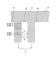
次に、レーダ波がアンテナ部62からレドーム20を経てレーダ装置1の外部へ送信される場合を例にとって、壁部41の作用を説明する。以下では、図4に示すように、第一壁体51、52の間を第一空気層82という。また、第一壁体52とレドーム20の側壁33との間を第二空気層84という。
次に、レーダ波がアンテナ部62からレドーム20を経てレーダ装置1の外部へ送信される場合を例にとって、壁部41の作用を説明する。以下では、図4に示すように、第一壁体51、52の間を第一空気層82という。また、第一壁体52とレドーム20の側壁33との間を第二空気層84という。
レドーム空間18、第一壁体51、第一空気層82、第一壁体52、及び第二空気層84を経て外部へ送信されるレーダ波の経路は種々考えられるが、ここでは例として、第一壁体51に入射し、第一壁体内で反射されること無くそのまま第一壁体51から出射される経路を第1経路71とする。また、第一壁体51に入射し、第一壁体51と第一空気層82との境界及び第一壁体51とレドーム空間18との境界で反射された後、第一壁体51から出射される経路、すなわち第一壁体51で多重反射される経路を第2経路72とする。
さらにまた、第一空気層82に出射され、第一空気層82で反射されること無くそのまま第一壁体52に入射する経路を第3経路73とする。また、第一空気層82に出射され、第一空気層82と第一壁体52との境界及び第一空気層82と第一壁体51との境界で反射された後、第一壁体52に入射する経路、すなわち第一空気層82で多重反射された経路を第4経路74とする。
ここで、第一壁体51に同位相で入射したレーダ波のうち、第1経路71を経て第一壁体51から出射されるレーダ波と、第2経路を経て第一壁体51から出射されるレーダ波とでは、第一壁体51でのレーダ波の波長の二分の一の値の経路差が生じる。すなわち、これらのレーダ波は、二分の一波長だけ位相がずれたものとなるため、互いに打消しあうように作用する。
同様に、同位相で第一空気層82に出射されたレーダ波のうち、第3経路73及び第4経路74を経て第一壁体52へ入射するレーダ波においても、第一空気層82におけるレーダ波の波長の二分の一の値の経路差が生じ、これらのレーダ波は互いに打消しあうように作用する。
ここでは第1経路71~第4経路74について例を挙げて説明したが、その他、レーダ波がアンテナ部62から壁部41を経てレーダ装置1の外部へ送信される種々の経路において、上記のようにレーダ波同士の経路差が波長の二分の一の値となる場合、または該波長の二分の一の奇数倍となる場合に、これらのレーダ波同士が互いに打ち消し合うように作用する。
<効果>
以上説明したように、本実施形態のレーダ装置1では、第一壁体51、52を透過するレーダ波同士が経路差によって互いに打ち消し合う状態が生じるように、第一壁体51、52からなる壁部41を設けたため、アンテナ部62のビーム方向aから外れた方向へのレーダ波を減衰させることができる。具体的には、例えば図5(a)に示すように、アンテナ部62がメインローブM1及びサイドローブS1、S2からなる合成指向性を有する場合、壁部41を備えることによって、同図5(b)に示すように、アンテナ部62のビーム方向aから外れた方向に形成されるサイドローブS1、S2を抑制することができる。
以上説明したように、本実施形態のレーダ装置1では、第一壁体51、52を透過するレーダ波同士が経路差によって互いに打ち消し合う状態が生じるように、第一壁体51、52からなる壁部41を設けたため、アンテナ部62のビーム方向aから外れた方向へのレーダ波を減衰させることができる。具体的には、例えば図5(a)に示すように、アンテナ部62がメインローブM1及びサイドローブS1、S2からなる合成指向性を有する場合、壁部41を備えることによって、同図5(b)に示すように、アンテナ部62のビーム方向aから外れた方向に形成されるサイドローブS1、S2を抑制することができる。
なお、壁部41は、レドーム20の内側に設けられているため、レーダ装置1の外形形状(サイズ)に影響を及ぼすことがない。したがって、レーダ装置1の小型化を妨げることなく、所望の指向性を実現することができる。
また、開口投影部39から該開口投影部39の外部を向く方向に、間隔tt1を値t3に設定して、さらに第一壁体を配置して壁部41を構成してもよい。第一壁体の数を増やすことにより、ビーム方向aから外れた方向に形成されるサイドローブS1、S2をさらに抑制することができる。
さらにまた、第一空気層82を透過するときの経路差によってレーダ波同士が互いに打ち消し合う状態が生じるように、隣接する第一壁体51及び第一壁体52の間隔を設定したため、アンテナ部62のビーム方向aから外れた方向へのレーダ波を効率よく減衰させることができる。
また、壁部41はレドーム20を形成する材料と同じ材料で形成されるため、壁部41とレドーム20とを同じ工程で製造することができる。つまり、製造工程を簡略化することができる。
[第二実施形態]
次に、本発明の第二実施形態のレーダ装置2について説明する。
なお、図6に示すレーダ装置2は、壁部43の構成が、第一実施形態のレーダ装置1のように第一壁体からなるものではなく、第一壁体52と、第一壁体52とは厚さの異なる第二壁体53とからなるものであるため、この相違する部分を中心に説明する。
次に、本発明の第二実施形態のレーダ装置2について説明する。
なお、図6に示すレーダ装置2は、壁部43の構成が、第一実施形態のレーダ装置1のように第一壁体からなるものではなく、第一壁体52と、第一壁体52とは厚さの異なる第二壁体53とからなるものであるため、この相違する部分を中心に説明する。
<壁部の構成>
壁部43は、第一壁体52と、第一壁体52より開口投影部39に近い側に配置された第二壁体53とからなる。第二壁体53は、下記の式(4)に示すように、第二壁体53中を伝播するレーダ波の波長の二分の一の値を2n-1倍(但し、nは自然数)した厚さt4を有する(但し、本実施形態では、第二壁体53の厚さtw3を式(4)にてn=1としたときの値に設定している)。
壁部43は、第一壁体52と、第一壁体52より開口投影部39に近い側に配置された第二壁体53とからなる。第二壁体53は、下記の式(4)に示すように、第二壁体53中を伝播するレーダ波の波長の二分の一の値を2n-1倍(但し、nは自然数)した厚さt4を有する(但し、本実施形態では、第二壁体53の厚さtw3を式(4)にてn=1としたときの値に設定している)。

<作用>
アンテナ部62から壁部43を経て外部へ送信されるレーダ波の経路として、例えば図7に示すように、第二壁体53の表面で反射され、レドーム空間18に戻る経路を第5経路75とする。また、第二壁体53に入射し、第二壁体53と第一空気層82との境界で反射され、レドーム空間18に戻る経路を第6経路76とする。
アンテナ部62から壁部43を経て外部へ送信されるレーダ波の経路として、例えば図7に示すように、第二壁体53の表面で反射され、レドーム空間18に戻る経路を第5経路75とする。また、第二壁体53に入射し、第二壁体53と第一空気層82との境界で反射され、レドーム空間18に戻る経路を第6経路76とする。
ここで、同位相で第二壁体53の表面に到達するレーダ波のうち、第5経路75による反射波では二分の一波長に相当する位相のずれが生じ、第6経路76による反射波では一波長に相当する位相のずれが生じる。つまり、第5経路75及び第6経路76により生じる反射波は、互いに打ち消し合うように作用する。
また、経路を図示していないが、第二壁体53、第一空気層82、第一壁体52、及び第二空気層84を経てレーダ装置2の外部へ送信されるレーダ波は、これらの壁体及び空気層にて減衰する。
<効果>
以上説明したように、レーダ装置2では、異なる厚さの第一壁体及び第二壁体からなる壁部43を設けたことにより、レドーム空間18へ戻される反射波同士を経路差によって互いに打ち消し合わせるとともに、外部へ送信されるレーダ波を減衰させることができる。
以上説明したように、レーダ装置2では、異なる厚さの第一壁体及び第二壁体からなる壁部43を設けたことにより、レドーム空間18へ戻される反射波同士を経路差によって互いに打ち消し合わせるとともに、外部へ送信されるレーダ波を減衰させることができる。
ところで、レドーム20の対向面37に第一壁体または第二壁体を設けると、これらの壁体を設けたことにより生じるレドーム空間18への反射波がアンテナ部62の合成指向性に影響を及ぼし、結果としてメインローブM2に乱れを生じさせることがある(図8参照)。
本実施形態によると、このような場合であっても、開口投影部39の少なくとも最も近くに第二壁体53が配置されているため、レドーム空間18への反射波が低減され、メインローブM2に生じる乱れを抑制することができる。
<他の実施形態>
以上、本発明の実施形態について説明したが、本発明は上記実施形態に限定されるものではなく、本発明の要旨を逸脱しない範囲において様々な態様にて実施することが可能である。
以上、本発明の実施形態について説明したが、本発明は上記実施形態に限定されるものではなく、本発明の要旨を逸脱しない範囲において様々な態様にて実施することが可能である。
(i)上記第一実施形態では、対向面37からの第一壁体51、52の高さが同じ値に設定されていたが、本発明はこれに限定されるものではない。代わりに、例えば、図9に示すレーダ装置3の壁部45のように、開口投影部39に近い側に位置する第一壁体55の高さを、第一壁体52の高さと比べて小さい値に設定してもよい。これにより、上記第二実施形態と同様に、壁体を設けたことにより生じるレドーム空間18への反射波を低減することができる。
(ii)上記第一実施形態では、第一壁体51、52はレドーム20を形成する材料と同じ材料で形成されていたが、本発明はこれに限定されるものではない。代わりに、例えば、図10に示すレーダ装置4のように、レドーム20を形成する透過材とは誘電率が異なり、かつ高損失でレーダ波を透過させる材料により第一壁体57、58を形成し、これらによって壁部47を構成してもよい。これにより、レーダ波が第一壁体57、58を透過するときの減衰量を増加させることができる。
(iii)上記第一実施形態では、第一壁体51、52のそれぞれの厚さtw1、tw2を、透過材中を伝播するレーダ波の波長の四分の一の値に設定していた。この値は式(2)にてn=1とした場合の値であるが、nは任意に定めた値(自然数)に設定してよい。
同様に、上記第一及び二実施形態では、第一空気層82の間隔tt1の値は、式(3)にて、nを任意に定めた値(自然数)に設定してよい。
また同様に、上記第二実施形態では、第二壁体の厚さtw3の値は、式(4)にて、nを任意に定めた値(自然数)に設定してよい。
また同様に、上記第二実施形態では、第二壁体の厚さtw3の値は、式(4)にて、nを任意に定めた値(自然数)に設定してよい。
(iv)上記第一実施形態では、第一壁体51、52は、開口投影部39の外形を囲む連続した壁状に形成されていたが、本発明はこれに限定されるものではない。代わりに、例えば、第一壁体51、52は、図11に示すように、複数の部分壁体69からなる構成であってもよい。
(v)また、上記第一実施形態では、第一壁体は、開口投影部39の外形を囲む壁状であったが、本発明はこれに限定されるものではない。代わりに、例えば、開口投影部39の外周の少なくとも一部に沿うように形成されていてもよい。具体的には、図12(a)、(b)に示すように、第一壁体91a、92b及び91b、92bは、開口投影部39の向かい合う一組の辺に沿って設けられた部分壁体69からなる構成であってもよい。つまり、第一壁体は、開口投影部39の外周に沿って断続的に形成されていてもよい。
さらにまた、図12(c)、(d)に示すように、第一壁体91c、92c及び91d、92dは、開口投影部39の向かい合う一組の辺に一部が沿うように設けられた部分壁体69からなる構成であってもよい。
また、図示していないが、第一壁体は、レーダ波を抑制する方向にだけ設けられていてもよい。
上記第二実施形態についても、同様の代替形態が可能である。
上記第二実施形態についても、同様の代替形態が可能である。
(vi)上記第一実施形態では、レドーム20の対向面37に、第一壁体51、52からなる壁部41が設けられていた。これに加えて、図13に示すように、レーダ装置5のレドーム20の側壁33に、レドーム空間18に向かって突出するように形成された第三壁体59を設けてもよい。第三壁体59は、例えば、レドーム20と同じ透過材で形成され、側壁33からの高さが、透過材中を伝播するレーダ波の波長の四分の一の値を2n-1倍(ただし、nは自然数)した値に設定される。第三壁体59は、法線方向aを上下方向として、この上下方向において回路基板60にできるだけ近い部位に設けられることが望ましい。これにより、回路基板60に沿う方向についても、外部に送信されるレーダ波を抑制することができる。
1・・・レーダ装置
10・・・本体
20・・・レドーム
37・・・対向面
39・・・開口投影部
41、43、45、47・・・壁部
51、52・・・第一壁体
53、92・・・第二壁体
55、58、57、91・・・第一壁体
62・・・アンテナ部
10・・・本体
20・・・レドーム
37・・・対向面
39・・・開口投影部
41、43、45、47・・・壁部
51、52・・・第一壁体
53、92・・・第二壁体
55、58、57、91・・・第一壁体
62・・・アンテナ部
Claims (11)
- 予め定められた周波数の電波からなるレーダ波の送信及び受信のうち少なくとも一方を行うアンテナ(62)と、
前記レーダ波を透過させるレドーム(20)と、
前記アンテナと対向する前記レドームの面を対向面(37)とし、該対向面に前記アンテナの開口面を該開口面の法線方向に投影した部位を開口投影部(39)として、前記レドームにより形成される空間に向かって前記対向面から突出し、前記開口投影部の外周の少なくとも一部に沿う壁部(41、43、45、47、91、92)と、
を備えることを特徴とするレーダ装置。 - 前記壁部(41、43、45、47)は、前記開口投影部の外周を連続的に囲むように形成されていること、を特徴とする請求項1に記載のレーダ装置。
- 前記壁部(41、43、45、47)は、前記開口投影部から該開口投影部の外部を向く方向に、間隔を隔てて配置された複数の壁体(51、52、53、55、58、57)からなることを特徴とする請求項1及び2に記載のレーダ装置。
- 前記壁体のうち少なくとも一つは、該壁体内での前記レーダ波の波長の四分の一を2n-1倍(但し、nは自然数)した厚さを有する第一壁体(51、52、55、58、57)からなることを特徴とする請求項3に記載のレーダ装置。
- 前記壁体のうち少なくとも一つは、該壁体内での前記レーダ波の波長の二分の一を2n-1倍(但し、nは自然数)した厚さを有する第二壁体(53)からなることを特徴とする請求項3または4に記載のレーダ装置。
- 前記壁体は、該壁体内での前記レーダ波の波長の四分の一を2n-1倍(但し、nは自然数)した厚さを有する少なくとも一つの第一壁体(52)と、該壁体内での前記レーダ波の波長の四分の一を2n-1倍(但し、nは自然数)した厚さを有する少なくとも一つの第二壁体(53)とを備え、
前記第二壁体は、前記第一壁体より、前記開口投影部に近い側に配置されることを特徴とする請求項3に記載のレーダ装置。 - 前記壁体(51、52、53、55、57、58)は、隣接する前記壁体との間隔が前記レドームにより形成される空間内での前記レーダ波の波長の四分の一を2n-1倍(但し、nは自然数)した値となるように配置されていることを特徴とする請求項3から6のいずれか一項に記載のレーダ装置。
- 前記壁体(55)は、該壁体によって反射される前記レーダ波を抑制するように、前記対向面からの突出量が設定されていることを特徴とする請求項1から7のいずれか一項に記載のレーダ装置。
- 少なくとも前記開口投影部の最も近くに配置されている前記壁体(55)は、隣接する前記壁体(52)と比べて、前記対向面からの突出量が小さく設定されていることを特徴とする請求項8に記載のレーダ装置。
- 前記壁体(51、52、53、55)は、前記レドームを形成する材料と同じ材料で形成されていることを特徴とする請求項1から9のいずれか一項に記載のレーダ装置。
- 前記壁体(57、58)は、前記レドームを形成する材料と比べて電波をより減衰させる材料で形成されていることを特徴とする請求項1から9のいずれか一項に記載のレーダ装置。
Priority Applications (2)
| Application Number | Priority Date | Filing Date | Title |
|---|---|---|---|
| CN201380037379.7A CN104487862B (zh) | 2012-07-13 | 2013-07-04 | 雷达装置 |
| US14/414,359 US9780443B2 (en) | 2012-07-13 | 2013-07-04 | Radar apparatus |
Applications Claiming Priority (2)
| Application Number | Priority Date | Filing Date | Title |
|---|---|---|---|
| JP2012-157998 | 2012-07-13 | ||
| JP2012157998A JP6171277B2 (ja) | 2012-07-13 | 2012-07-13 | レーダ装置 |
Publications (1)
| Publication Number | Publication Date |
|---|---|
| WO2014010502A1 true WO2014010502A1 (ja) | 2014-01-16 |
Family
ID=49915960
Family Applications (1)
| Application Number | Title | Priority Date | Filing Date |
|---|---|---|---|
| PCT/JP2013/068344 Ceased WO2014010502A1 (ja) | 2012-07-13 | 2013-07-04 | レーダ装置 |
Country Status (4)
| Country | Link |
|---|---|
| US (1) | US9780443B2 (ja) |
| JP (1) | JP6171277B2 (ja) |
| CN (1) | CN104487862B (ja) |
| WO (1) | WO2014010502A1 (ja) |
Families Citing this family (31)
| Publication number | Priority date | Publication date | Assignee | Title |
|---|---|---|---|---|
| WO2013123089A1 (en) * | 2012-02-17 | 2013-08-22 | Cohen Nathaniel L | Apparatus for using microwave energy for insect and pest control and methods thereof |
| DE102013220259A1 (de) * | 2013-10-08 | 2015-04-09 | Robert Bosch Gmbh | Radarsensor mit Radom |
| JP6326920B2 (ja) * | 2014-04-04 | 2018-05-23 | 株式会社Soken | レーダ装置 |
| JP2016006411A (ja) * | 2014-05-27 | 2016-01-14 | パナソニックIpマネジメント株式会社 | ミリ波用アンテナ及び車載用レーダ装置 |
| JP6235424B2 (ja) * | 2014-07-01 | 2017-11-22 | 株式会社Soken | アンテナ装置 |
| US10082571B2 (en) * | 2014-09-30 | 2018-09-25 | Nidec Elesys Corporation | Monitoring apparatus |
| WO2016182567A1 (en) * | 2015-05-13 | 2016-11-17 | GM Global Technology Operations LLC | Structure between radar and fascia |
| EP3107151B1 (en) * | 2015-06-17 | 2022-04-27 | Volvo Car Corporation | Low reflection radar bracket |
| JP6802995B2 (ja) * | 2016-07-20 | 2020-12-23 | スズキ株式会社 | 車両用センサ周辺構造 |
| JP6968527B2 (ja) * | 2016-10-24 | 2021-11-17 | 豊田合成株式会社 | 電波透過性カバー |
| KR101877645B1 (ko) * | 2016-12-12 | 2018-07-11 | 재단법인대구경북과학기술원 | 외부 영향을 최소화하는 투과형 레이더 장치 |
| US10389019B2 (en) * | 2016-12-17 | 2019-08-20 | Point Road Solutions, Llc | Methods and systems for wet radome attenuation mitigation in phased-array antennae applications and networked use of such applications |
| KR102065025B1 (ko) * | 2017-01-20 | 2020-01-10 | 주식회사 인비지블 | 자동차용 레이더의 전자기파 투과 부재 |
| JP6840564B2 (ja) * | 2017-02-21 | 2021-03-10 | 日本無線株式会社 | 平面アンテナ装置 |
| JP6738763B2 (ja) * | 2017-04-18 | 2020-08-12 | 株式会社Soken | レーダ装置 |
| DE102017218103B4 (de) | 2017-10-11 | 2024-06-13 | Vitesco Technologies GmbH | Gehäuse für einen Radarsensor und Vorrichtung zur Übertragung elektrischer Energie mittels induktiver Kopplung |
| CN107843878A (zh) * | 2017-11-08 | 2018-03-27 | 绍兴上虞威拓机械电子有限公司 | 一种电子雷达装置 |
| JP6693682B2 (ja) * | 2018-03-23 | 2020-05-13 | 三菱電機株式会社 | レーダ装置 |
| JP7099861B2 (ja) * | 2018-04-23 | 2022-07-12 | 株式会社デンソーテン | レーダ装置 |
| JP7163209B2 (ja) * | 2019-02-06 | 2022-10-31 | 日立Astemo株式会社 | レーダ装置 |
| JP7095625B2 (ja) * | 2019-03-01 | 2022-07-05 | 株式会社デンソー | 車載用レーダ装置 |
| US11226397B2 (en) * | 2019-08-06 | 2022-01-18 | Waymo Llc | Slanted radomes |
| US11385325B2 (en) * | 2019-08-07 | 2022-07-12 | Waymo Llc | Corrugated radomes |
| CN110542800B (zh) * | 2019-08-12 | 2021-08-17 | 中国电子科技集团公司第四十一研究所 | 一种可调节的电厚度贴合反射测试波导探头设计方法 |
| EP3798676B1 (en) * | 2019-09-24 | 2025-08-27 | Qualcomm Auto Ltd. | A radar side-shield and a radar transceiver assembly |
| JP7499460B2 (ja) * | 2019-09-30 | 2024-06-14 | パナソニックIpマネジメント株式会社 | 照明器具 |
| JP7417491B2 (ja) * | 2020-07-31 | 2024-01-18 | 株式会社Soken | レーダ装置 |
| JP7579358B2 (ja) | 2020-12-07 | 2024-11-07 | 日立Astemo株式会社 | レーダ装置 |
| KR102952337B1 (ko) | 2021-04-02 | 2026-04-14 | 삼성전자주식회사 | 안테나 레이돔 및 이를 포함하는 전자 장치 |
| KR20240035375A (ko) | 2021-08-05 | 2024-03-15 | 닛토덴코 가부시키가이샤 | 전자파 실드 |
| EP4641831A1 (en) * | 2024-04-23 | 2025-10-29 | Aptiv Technologies AG | Radar radome with rib structure |
Citations (5)
| Publication number | Priority date | Publication date | Assignee | Title |
|---|---|---|---|---|
| JP2001044750A (ja) * | 1998-12-28 | 2001-02-16 | Tokai Rubber Ind Ltd | 透明電波吸収体 |
| JP2005249659A (ja) * | 2004-03-05 | 2005-09-15 | Mitsubishi Electric Corp | レーダ装置用送受信アンテナ |
| JP2007013311A (ja) * | 2005-06-28 | 2007-01-18 | Murata Mfg Co Ltd | アンテナモジュールおよび無線装置 |
| JP2010210297A (ja) * | 2009-03-09 | 2010-09-24 | Furukawa Electric Co Ltd:The | 広覆域レーダ装置 |
| JP2012093305A (ja) * | 2010-10-28 | 2012-05-17 | Denso Corp | レーダ装置、レドーム |
Family Cites Families (5)
| Publication number | Priority date | Publication date | Assignee | Title |
|---|---|---|---|---|
| JP2003243920A (ja) | 2002-02-18 | 2003-08-29 | Mitsubishi Electric Corp | レドーム |
| JP3764877B2 (ja) * | 2002-10-16 | 2006-04-12 | 株式会社日立製作所 | レーダ装置 |
| JP2004325160A (ja) | 2003-04-23 | 2004-11-18 | Hitachi Ltd | 車載用レーダ |
| JP2005109687A (ja) | 2003-09-29 | 2005-04-21 | Mitsumi Electric Co Ltd | アンテナ装置 |
| JP5603636B2 (ja) * | 2010-04-09 | 2014-10-08 | 古野電気株式会社 | レドーム、アンテナ装置、およびレーダ装置 |
-
2012
- 2012-07-13 JP JP2012157998A patent/JP6171277B2/ja active Active
-
2013
- 2013-07-04 WO PCT/JP2013/068344 patent/WO2014010502A1/ja not_active Ceased
- 2013-07-04 CN CN201380037379.7A patent/CN104487862B/zh active Active
- 2013-07-04 US US14/414,359 patent/US9780443B2/en active Active
Patent Citations (5)
| Publication number | Priority date | Publication date | Assignee | Title |
|---|---|---|---|---|
| JP2001044750A (ja) * | 1998-12-28 | 2001-02-16 | Tokai Rubber Ind Ltd | 透明電波吸収体 |
| JP2005249659A (ja) * | 2004-03-05 | 2005-09-15 | Mitsubishi Electric Corp | レーダ装置用送受信アンテナ |
| JP2007013311A (ja) * | 2005-06-28 | 2007-01-18 | Murata Mfg Co Ltd | アンテナモジュールおよび無線装置 |
| JP2010210297A (ja) * | 2009-03-09 | 2010-09-24 | Furukawa Electric Co Ltd:The | 広覆域レーダ装置 |
| JP2012093305A (ja) * | 2010-10-28 | 2012-05-17 | Denso Corp | レーダ装置、レドーム |
Also Published As
| Publication number | Publication date |
|---|---|
| CN104487862A (zh) | 2015-04-01 |
| US9780443B2 (en) | 2017-10-03 |
| CN104487862B (zh) | 2017-09-19 |
| JP6171277B2 (ja) | 2017-08-02 |
| US20150207217A1 (en) | 2015-07-23 |
| JP2014020846A (ja) | 2014-02-03 |
Similar Documents
| Publication | Publication Date | Title |
|---|---|---|
| JP6171277B2 (ja) | レーダ装置 | |
| JP5953969B2 (ja) | レーダ装置 | |
| JP5661423B2 (ja) | レーダ装置 | |
| CN110546815B (zh) | 天线装置 | |
| WO2017146163A1 (ja) | アンテナ装置 | |
| JP2019158592A (ja) | アンテナ装置 | |
| JP2024517921A (ja) | 自動車レーダアプリケーション用のアンテナ装置 | |
| JP2017211199A (ja) | レーダ装置 | |
| JP7313009B2 (ja) | レーダ装置 | |
| JP2005249659A (ja) | レーダ装置用送受信アンテナ | |
| WO2014069658A1 (ja) | 高周波モジュール | |
| JP6235424B2 (ja) | アンテナ装置 | |
| JP6704169B2 (ja) | 誘電体基板及びアンテナ装置 | |
| JP7132167B2 (ja) | レーダ装置及びレーダ装置用ブラケット | |
| US20240069155A1 (en) | Radar apparatus | |
| JP6608775B2 (ja) | 車載用周波数選択板および車載レーダシステム | |
| US12300881B2 (en) | Radar device | |
| JP2007235287A (ja) | 車載用電波レーダ装置 | |
| JP5041416B2 (ja) | アンテナ装置 | |
| JP6198216B1 (ja) | リフレクトアレーアンテナ | |
| JP5981466B2 (ja) | 平面伝送線路導波管変換器 | |
| JP5952718B2 (ja) | アンテナ装置、その反射板 | |
| JP2017229231A (ja) | 電磁波漏洩防止装置および無線電力伝送システム | |
| US20210092511A1 (en) | Speaker | |
| JP2007228435A (ja) | スロットアンテナ |
Legal Events
| Date | Code | Title | Description |
|---|---|---|---|
| 121 | Ep: the epo has been informed by wipo that ep was designated in this application |
Ref document number: 13817616 Country of ref document: EP Kind code of ref document: A1 |
|
| WWE | Wipo information: entry into national phase |
Ref document number: 14414359 Country of ref document: US |
|
| NENP | Non-entry into the national phase |
Ref country code: DE |
|
| 122 | Ep: pct application non-entry in european phase |
Ref document number: 13817616 Country of ref document: EP Kind code of ref document: A1 |