WO2014003189A1 - 円偏光板および有機elパネル - Google Patents
円偏光板および有機elパネル Download PDFInfo
- Publication number
- WO2014003189A1 WO2014003189A1 PCT/JP2013/067956 JP2013067956W WO2014003189A1 WO 2014003189 A1 WO2014003189 A1 WO 2014003189A1 JP 2013067956 W JP2013067956 W JP 2013067956W WO 2014003189 A1 WO2014003189 A1 WO 2014003189A1
- Authority
- WO
- WIPO (PCT)
- Prior art keywords
- polarizing plate
- dihydroxy compound
- retardation film
- polarizer
- group
- Prior art date
- Legal status (The legal status is an assumption and is not a legal conclusion. Google has not performed a legal analysis and makes no representation as to the accuracy of the status listed.)
- Ceased
Links
Images


Classifications
-
- G—PHYSICS
- G02—OPTICS
- G02B—OPTICAL ELEMENTS, SYSTEMS OR APPARATUS
- G02B5/00—Optical elements other than lenses
- G02B5/30—Polarising elements
- G02B5/3025—Polarisers, i.e. arrangements capable of producing a definite output polarisation state from an unpolarised input state
- G02B5/3033—Polarisers, i.e. arrangements capable of producing a definite output polarisation state from an unpolarised input state in the form of a thin sheet or foil, e.g. Polaroid
- G02B5/3041—Polarisers, i.e. arrangements capable of producing a definite output polarisation state from an unpolarised input state in the form of a thin sheet or foil, e.g. Polaroid comprising multiple thin layers, e.g. multilayer stacks
- G02B5/305—Polarisers, i.e. arrangements capable of producing a definite output polarisation state from an unpolarised input state in the form of a thin sheet or foil, e.g. Polaroid comprising multiple thin layers, e.g. multilayer stacks including organic materials, e.g. polymeric layers
-
- H—ELECTRICITY
- H10—SEMICONDUCTOR DEVICES; ELECTRIC SOLID-STATE DEVICES NOT OTHERWISE PROVIDED FOR
- H10K—ORGANIC ELECTRIC SOLID-STATE DEVICES
- H10K50/00—Organic light-emitting devices
- H10K50/80—Constructional details
- H10K50/86—Arrangements for improving contrast, e.g. preventing reflection of ambient light
-
- G—PHYSICS
- G02—OPTICS
- G02B—OPTICAL ELEMENTS, SYSTEMS OR APPARATUS
- G02B1/00—Optical elements characterised by the material of which they are made; Optical coatings for optical elements
- G02B1/08—Optical elements characterised by the material of which they are made; Optical coatings for optical elements made of polarising materials
-
- G—PHYSICS
- G02—OPTICS
- G02B—OPTICAL ELEMENTS, SYSTEMS OR APPARATUS
- G02B5/00—Optical elements other than lenses
- G02B5/30—Polarising elements
- G02B5/3025—Polarisers, i.e. arrangements capable of producing a definite output polarisation state from an unpolarised input state
-
- G—PHYSICS
- G02—OPTICS
- G02B—OPTICAL ELEMENTS, SYSTEMS OR APPARATUS
- G02B5/00—Optical elements other than lenses
- G02B5/30—Polarising elements
- G02B5/3083—Birefringent or phase retarding elements
-
- H—ELECTRICITY
- H10—SEMICONDUCTOR DEVICES; ELECTRIC SOLID-STATE DEVICES NOT OTHERWISE PROVIDED FOR
- H10K—ORGANIC ELECTRIC SOLID-STATE DEVICES
- H10K50/00—Organic light-emitting devices
- H10K50/80—Constructional details
- H10K50/868—Arrangements for polarized light emission
-
- H—ELECTRICITY
- H10—SEMICONDUCTOR DEVICES; ELECTRIC SOLID-STATE DEVICES NOT OTHERWISE PROVIDED FOR
- H10K—ORGANIC ELECTRIC SOLID-STATE DEVICES
- H10K59/00—Integrated devices, or assemblies of multiple devices, comprising at least one organic light-emitting element covered by group H10K50/00
- H10K59/50—OLEDs integrated with light modulating elements, e.g. with electrochromic elements, photochromic elements or liquid crystal elements
-
- H—ELECTRICITY
- H10—SEMICONDUCTOR DEVICES; ELECTRIC SOLID-STATE DEVICES NOT OTHERWISE PROVIDED FOR
- H10K—ORGANIC ELECTRIC SOLID-STATE DEVICES
- H10K59/00—Integrated devices, or assemblies of multiple devices, comprising at least one organic light-emitting element covered by group H10K50/00
- H10K59/80—Constructional details
- H10K59/8791—Arrangements for improving contrast, e.g. preventing reflection of ambient light
Definitions
- the present invention relates to a circularly polarizing plate and an organic EL panel.
- Patent Document 1 a combination of a ⁇ / 4 plate and a ⁇ / 2 plate is used (Patent Document 1), and a ⁇ / 4 plate made of a so-called reverse dispersion wavelength material is used ( Patent Document 2) has been proposed.
- the circularly polarizing plate when a circularly polarizing plate is used in the organic EL panel, it is preferable that the circularly polarizing plate is as thin as possible in consideration of a demand for thinning the organic EL panel.
- a ⁇ / 4 plate and a ⁇ / 2 It is required to avoid using a combination of two plates as much as possible.
- a ⁇ / 4 plate made of a reverse dispersion wavelength material is used as in the technique of Patent Document 2
- the organic EL panel using the technique of Patent Document 2 has a problem that the panel itself is warped, resulting in uneven reflection. JP-A-5-27118 JP 2006-171235 A
- the present invention has been made in order to solve the above-described conventional problems.
- the object of the present invention is to prevent light leakage of the organic EL panel and suppress warpage, thereby reducing reflection unevenness within the panel surface. It is providing the circularly-polarizing plate which can reduce this.
- the circularly polarizing plate of the present invention includes a polarizer and a retardation film directly bonded to the polarizer, and the in-plane retardation of the retardation film has a relationship of Re (450) ⁇ Re (550).
- Re (450) and Re (550) represent in-plane retardation measured at wavelengths of 450 nm and 550 nm at 23 ° C., respectively.
- This circularly polarizing plate is used for an organic EL panel.
- the retardation film is subjected to corona treatment or plasma treatment.
- the said circularly-polarizing plate further has an easily bonding layer between the said polarizer and the said phase difference film.
- the polarizer and the retardation film are long, and the retardation film satisfies a relationship of 35 ° ⁇ ⁇ ⁇ 55 °.
- the retardation film includes a resin having a repeating unit derived from an aliphatic monomer.
- the retardation film includes at least one selected from the group consisting of a polycarbonate resin and a polyvinyl acetal resin.
- the polycarbonate resin includes a structural unit derived from a dihydroxy compound having an etheric oxygen atom in at least one ⁇ -position or ⁇ -position of a carbon atom bonded to a hydroxy group.
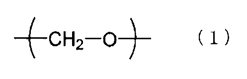
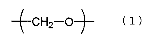
- the etheric oxygen atom of the dihydroxy compound having an etheric oxygen atom is an oxygen atom having a structure represented by the following formula (1).
- the dihydroxy compound having an etheric oxygen atom is a dihydroxy compound represented by the following formula (2).
- R 1 to R 4 each independently have a hydrogen atom, an optionally substituted alkyl group having 1 to 20 carbon atoms, or an optionally substituted group.
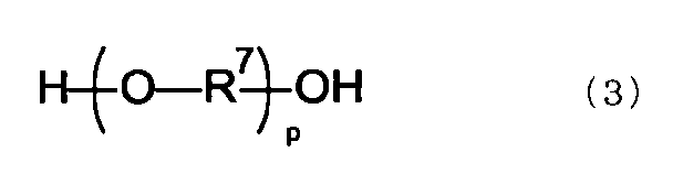
- the dihydroxy compound having an etheric oxygen atom is a dihydroxy compound represented by the following formula (3).
- R 7 represents a substituted or unsubstituted alkylene group having 2 to 10 carbon atoms, and p is an integer of 2 to 100.
- the dihydroxy compound having an etheric oxygen atom has a cyclic ether structure.
- the dihydroxy compound having an etheric oxygen atom has a plurality of cyclic structures.
- the polycarbonate resin is derived from one or more dihydroxy compounds selected from the group consisting of a dihydroxy compound represented by the following formula (6) and a dihydroxy compound represented by the following formula (7). Includes structural units.
- the polycarbonate resin includes a structural unit derived from an aromatic dicarboxylic acid.
- the polycarbonate resin includes a structural unit derived from an aromatic dihydroxy compound.
- the aromatic dihydroxy compound is 2,2-bis (4-hydroxyphenyl) propane.
- the circularly polarizing plate used for the organic EL panel excellent durability is obtained by setting the 90 ° adhesive force between the polarizer and the retardation film to 1.0 N / 20 mm or more. And a retardation film can be used in a state where they are directly bonded together, and warpage can be suppressed to reduce reflection unevenness in the panel surface.
- FIG. 6 is an image showing an observation result of reflection unevenness of the organic EL panel of Example 1.
- FIG. It is an image which shows the observation result of the reflective nonuniformity of the organic electroluminescent panel of the comparative example 1-2.
- Refractive index (nx, ny, nz) “Nx” is the refractive index in the direction in which the in-plane refractive index is maximum (ie, the slow axis direction), and “ny” is the direction orthogonal to the slow axis in the plane (ie, the fast axis direction). “Nz” is the refractive index in the thickness direction.
- Refractive index (nx, ny, nz) “Nx” is the refractive index in the direction in which the in-plane refractive index is maximum (ie, the slow axis direction), and “ny” is the direction orthogonal to the slow axis in the plane (ie, the fast axis direction). “Nz” is the refractive index in the thickness direction.
- In-plane retardation (Re) “Re (550)” is the in-plane retardation of the film measured with light having a wavelength of 550 nm at 23 ° C.
- Re (450) is the in-plane retardation of the film measured with light having a wavelength of 450 nm at 23 ° C.
- Thickness direction retardation (Rth) is a retardation in the thickness direction of the film measured with light having a wavelength of 550 nm at 23 ° C.
- FIG. 1 is a schematic cross-sectional view of a circularly polarizing plate according to a preferred embodiment of the present invention.
- the circularly polarizing plate 100 of this embodiment includes a polarizer 10, a protective film 20 disposed on one side of the polarizer 10, and a retardation film 30 disposed on the other side of the polarizer 10.
- the polarizer 10 and the retardation film 30 are directly bonded (that is, not via a protective film), and the retardation film 30 also functions as a protective film for the polarizer 10. obtain.
- the polarizer and the retardation film are directly bonded to each other, when the circularly polarizing plate is applied to the organic EL panel, the warpage of the panel is suppressed, and as a result, reflection unevenness can be reduced. .
- the dimensional change of the polarizer can be suppressed by directly bonding the polarizer and the retardation film when the polarizer greatly affects the dimensional change.
- the retardation film exhibits the so-called reverse dispersion wavelength dependency.
- the in-plane retardation satisfies the relationship Re (450) ⁇ Re (550).
- the 90 ° adhesive force between the polarizer 10 and the retardation film 30 (hereinafter sometimes simply referred to as adhesive force) is 1.0 N / 20 mm or more, preferably 1. 1N / 20mm or more, more preferably 1.5N / 20mm or more.
- a practical upper limit of the adhesive force is, for example, 10.0 N / 20 mm.
- the polarizer and the retardation film can be used directly (without a protective film),
- warpage of the panel can be suppressed, and as a result, reflection unevenness can be reduced.
- This is a knowledge obtained for the first time as a result of trial and error after mounting a circularly polarizing plate on an organic EL panel.
- the present invention due to the synergistic effect of optimization of adhesive strength and direct bonding of the polarizer and the retardation film, the warp of the organic EL panel is suppressed very well, and the uneven reflection is remarkable. Can be reduced.
- the retardation film 30 has a refractive index characteristic of nx> ny and has a slow axis.
- the polarizer 10 and the retardation film 30 are laminated so that the absorption axis of the polarizer 10 and the slow axis of the retardation film 30 form a predetermined angle.
- the angle ⁇ formed by the absorption axis of the polarizer 10 and the slow axis of the retardation film 30 is preferably 35 ° ⁇ ⁇ ⁇ 55 °, more preferably 38 ° ⁇ ⁇ ⁇ 52 °, and even more preferably 39 ° ⁇ ⁇ .
- the relationship of ⁇ 51 ° is satisfied. Note that when an angle is referred to in this specification, the angle includes both clockwise and counterclockwise angles unless otherwise specified.
- the circularly polarizing plate 100 is long, and thus the polarizer 10 and the retardation film 30 are also long.
- the long circularly polarizing plate can be stored and / or transported by being wound into a roll, for example.
- the absorption axis of the polarizer corresponds to the long direction.
- the angle ⁇ formed between the slow axis of the retardation film 30 and the longitudinal direction is preferably 35 ° ⁇ ⁇ ⁇ 55 °, more preferably 38 ° ⁇ ⁇ ⁇ 52 °, and further preferably 39 ° ⁇ ⁇ ⁇ . Satisfies 51 ° relationship.
- the thickness of the entire circularly polarizing plate of the present invention varies depending on its configuration, but is typically about 40 ⁇ m to 300 ⁇ m.
- each layer which comprises the circularly-polarizing plate of this invention is demonstrated.
- Polarizer Any appropriate polarizer can be adopted as the polarizer. Specific examples include hydrophilic polymer films such as polyvinyl alcohol films, partially formalized polyvinyl alcohol films, and ethylene / vinyl acetate copolymer partially saponified films, and dichroic substances such as iodine and dichroic dyes.
- Examples thereof include polyene-based oriented films such as those subjected to the dyeing treatment and stretching treatment according to the above, polyvinyl alcohol dehydrated products and polyvinyl chloride dehydrochlorinated products.
- a polarizer obtained by dyeing a polyvinyl alcohol film with iodine and uniaxially stretching is used because of excellent optical properties.
- the dyeing with iodine is performed, for example, by immersing a polyvinyl alcohol film in an iodine aqueous solution.
- the stretching ratio of the uniaxial stretching is preferably 3 to 7 times. The stretching may be performed after the dyeing treatment or may be performed while dyeing. Moreover, you may dye
- the polyvinyl alcohol film is subjected to swelling treatment, crosslinking treatment, washing treatment, drying treatment and the like.
- swelling treatment for example, by immersing a polyvinyl alcohol film in water and washing it before dyeing, not only can the surface of the polyvinyl alcohol film be cleaned and anti-blocking agents can be washed, but the polyvinyl alcohol film can be swollen and dyed Unevenness can be prevented.
- the thickness of the polarizer is typically about 1 ⁇ m to 80 ⁇ m.
- A-2. Retardation film As described above, the retardation film has a refractive index characteristic of nx> ny.
- the in-plane retardation Re (550) of the retardation film is preferably 100 nm to 180 nm, more preferably 135 nm to 155 nm. As described above, the retardation film exhibits so-called reverse dispersion wavelength dependency. Specifically, the in-plane retardation satisfies the relationship Re (450) ⁇ Re (550). Re (450) / Re (550) is preferably 0.8 or more and less than 1.0.
- the retardation film exhibits any suitable refractive index ellipsoid as long as it has a relationship of nx> ny. Preferably, the refractive index ellipsoid of the retardation film exhibits a relationship of nx> ny ⁇ nz.
- the Nz coefficient of the retardation film is preferably 1.05 to 2.0. By satisfying such a relationship, color loss can be prevented more favorably.
- the retardation film is formed of any appropriate resin that can realize the adhesive force with the polarizer as described above and satisfy the optical characteristics.
- the resin forming the retardation film include polycarbonate resins, polyvinyl acetal resins, cycloolefin resins, acrylic resins, and cellulose ester resins.
- polycarbonate resin and polyvinyl acetal resin are used.
- the resins forming the retardation film may be used alone or in combination according to desired properties.
- the polycarbonate resin can be produced, for example, by a melt polymerization method in which a dihydroxy compound and a carbonic acid diester are reacted.
- the carbonic acid diester include dialkyl carbonates such as diaryl carbonate, dimethyl carbonate, diethyl carbonate, and di-t-butyl carbonate which may have a substituent such as diphenyl carbonate and ditolyl carbonate.
- diaryl carbonate which may have a substituent such as diphenyl carbonate and ditolyl carbonate is preferably used, and diphenyl carbonate is particularly preferably used.
- These carbonic acid diesters may be used alone or in combination of two or more.
- Carbonic acid diesters may contain impurities such as chloride ions, which may hinder the polymerization reaction or worsen the hue of the resulting polycarbonate resin. It is preferable to use what was done.
- a part of the carbonic acid diester may be substituted with dicarboxylic acid or an ester thereof in an amount of 50 mol% or less, preferably 30 mol% or less. Examples of such dicarboxylic acids or esters thereof include terephthalic acid, isophthalic acid, diphenyl terephthalate, and diphenyl isophthalate.
- the polycarbonate resin may be referred to as a polyester carbonate resin.
- the polycarbonate resin of the present embodiment can be produced by, for example, a melt polymerization method in which a dihydroxy compound and a carbonic acid diester are reacted.
- a polycarbonate resin can be usually produced. Any compound can be used, but at least one of the dihydroxy compounds is preferably a dihydroxy compound having an etheric oxygen atom in at least one ⁇ -position or ⁇ -position of the carbon atom bonded to the hydroxy group.
- the “etheric oxygen atom” in the dihydroxy compound of the present embodiment means that the oxygen atom is single-bonded with two carbons, and is distinguished from the oxygen atom constituting the hydroxyl group or carbonyl group.
- the ⁇ -position and ⁇ -position are the carbon atoms bonded to the hydroxy group in the dihydroxy compound.
- the position of the adjacent carbon atom is ⁇ -position
- the adjacent carbon atom is ⁇ -position
- the adjacent carbon atom is ⁇ -position.
- the carbon atom corresponding to the ⁇ -position is an etheric oxygen atom based on the carbon atom bonded to the hydroxy group
- “the ⁇ -position of the carbon atom bonded to the hydroxy group is Corresponds to “aliphatic dihydroxy compound having an etheric oxygen atom”.
- the etheric oxygen atom is preferably a part of the structure represented by the following formula (1), specifically, at least bonded to a methylene group.
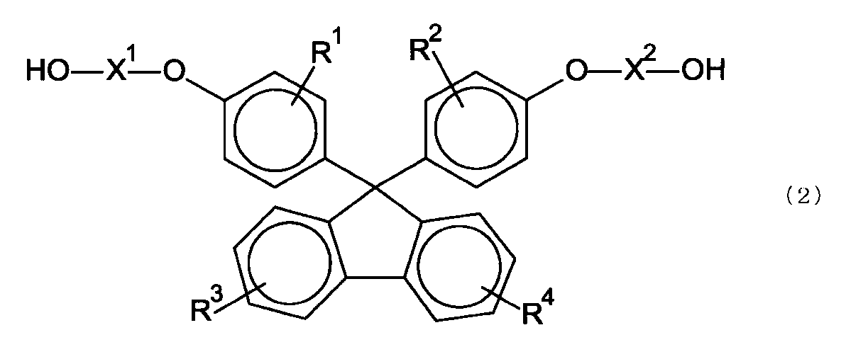
- the dihydroxy compound having an etheric oxygen atom is preferably a dihydroxy compound represented by the following formula (2).
- R 1 ⁇ R 4 Each independently represents a hydrogen atom, an optionally substituted alkyl group having 1 to 20 carbon atoms, an optionally substituted cycloalkyl group having 6 to 20 carbon atoms, or Represents an aryl group having 6 to 20 carbon atoms which may have a substituent.
- R 1 ⁇ R 4 There may be a plurality of each independently for each ring.
- X 1 And X 2 Has an optionally substituted alkylene group having 2 to 10 carbon atoms, an optionally substituted cycloalkylene group having 6 to 20 carbon atoms, or a substituent.
- the dihydroxy compound having an etheric oxygen atom is preferably a dihydroxy compound represented by the following formula (3).
- R 7 Represents a substituted or unsubstituted alkylene group having 2 to 10 carbon atoms
- p is an integer of 2 to 100.
- examples of other dihydroxy compounds having an etheric oxygen atom include compounds having a cyclic ether structure.
- the compound preferably has a plurality of etheric oxygen atoms, and preferably has a plurality of cyclic structures.
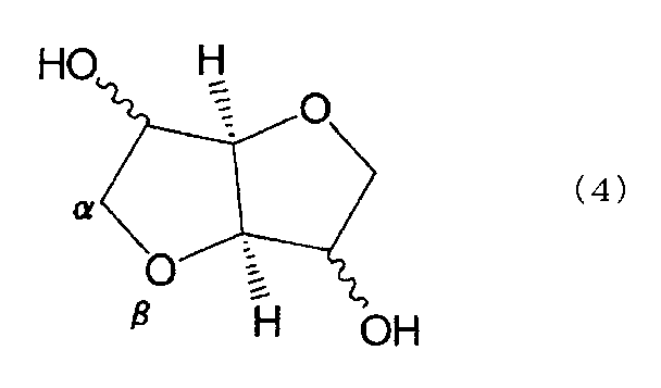
- a compound having a cyclic ether structure is more preferable. More specifically, compounds having a cyclic ether structure as represented by the following formulas (4) and (5) are exemplified.
- dihydroxy compound represented by the formula (4) examples include isosorbide, isomannide, and isoide which have a stereoisomeric relationship.
- isosorbide obtained by dehydrating condensation of sorbitol produced from various starches that are abundant as resources and are readily available is easy to obtain and manufacture, optical properties, moldability From the viewpoint of the above, it is most preferable.
- ⁇ Dihydroxy compound represented by the general formula (2) More specifically, as the dihydroxy compound represented by the general formula (2), 9,9-bis (4- (2-hydroxyethoxy) phenyl) fluorene, 9,9-bis (4- (2-hydroxy) Ethoxy) -3-methylphenyl) fluorene, 9,9-bis (4- (2-hydroxyethoxy) -3-isopropylphenyl) fluorene, 9,9-bis (4- (2-hydroxyethoxy) -3-isobutyl Phenyl) fluorene, 9,9-bis (4- (2-hydroxyethoxy) -3-tert-butylphenyl) fluorene, 9,9-bis (4- (2-hydroxyethoxy) -3-cyclohexylphenyl) fluorene, 9,9-bis (4- (2-hydroxyethoxy) -3-phenylphenyl) fluorene, 9,9-bis (4- (2-hydroxy Toxi) -3,5-dimethylphenyl) fluor
- the dihydroxy compound having an etheric oxygen atom may be used alone or in combination of two or more depending on the required performance of the polycarbonate resin to be obtained.
- the structural unit derived from the dihydroxy compound represented by formula (2), the structural unit derived from the dihydroxy compound represented by formula (3), and the dihydroxy represented by formula (4) It is preferable to include a structural unit derived from a compound.
- the dihydroxy having the etheric oxygen atom is used. It is preferable to use a dihydroxy compound other than the compound in combination. More specifically, the dihydroxy compound other than the dihydroxy compound having an etheric oxygen atom is selected from the group consisting of a dihydroxy compound represented by the following formula (6) and a dihydroxy compound represented by the following formula (7). One or more dihydroxy compounds.
- R 5 Represents a substituted or unsubstituted monocyclic cycloalkylene group having 4 to 20 carbon atoms.
- R 6 Represents a substituted or unsubstituted monocyclic cycloalkylene group having 4 to 20 carbon atoms.
- dihydroxy compound represented by Formula (6) examples include a compound containing a monocyclic cycloalkylene group (an alicyclic dihydroxy compound). By setting it as a monocyclic structure, the toughness when the polycarbonate resin obtained is used as a film can be improved.
- Representative examples of the alicyclic dihydroxy compound include compounds having a 5-membered ring structure or a 6-membered ring structure.
- a 5-membered ring structure or a 6-membered ring structure By being a 5-membered ring structure or a 6-membered ring structure, the heat resistance of the obtained polycarbonate resin can be increased.
- the six-membered ring structure may be fixed in a chair shape or a boat shape by a covalent bond. Specifically, 1,2-cyclopentanediol, 1,3-cyclopentanediol, 1,2-cyclohexanediol, 1,3-cyclohexanediol, 1,4-cyclohexanediol, 2-methyl-1,4- And cyclohexanediol.
- the dihydroxy compound represented by Formula (6) may be used independently and may be used in combination of 2 or more type.
- Examples of the dihydroxy compound represented by the formula (7) include a compound containing a monocyclic cycloalkylene group (an alicyclic dihydroxy compound). By setting it as a monocyclic structure, the toughness when the polycarbonate resin obtained is used as a film can be improved.
- R in the formula (7) is used as a typical example of the alicyclic dihydroxy compound. 6 Is represented by the following general formula (Ia) (wherein R 7 Represents a hydrogen atom or a substituted or unsubstituted alkyl group having 1 to 12 carbon atoms. ), And various isomers.
- Such isomers include 1,2-cyclohexanedimethanol, 1,3-cyclohexanedimethanol, 1,4-cyclohexanedimethanol and the like. These are easily available and excellent in handleability.
- the dihydroxy compound represented by the general formula (7) may be used alone or in combination of two or more.
- the compound illustrated above regarding the dihydroxy compound represented by Formula (6) and (7) is an example of the alicyclic dihydroxy compound which can be used, and is not limited to these at all.
- the polycarbonate resin of this embodiment may further contain a structural unit derived from another dihydroxy compound.
- Examples of other dihydroxy compounds include 9,9-bis (4-hydroxyphenyl) fluorene, 9,9-bis (4-hydroxy-3-methylphenyl) fluorene, and 9,9-bis (4-hydroxy-3).
- -Ethylphenyl) fluorene 9,9-bis (4-hydroxy-3-n-propylphenyl) fluorene, 9,9-bis (4-hydroxy-3-isopropylphenyl) fluorene, 9,9-bis (4- Hydroxy-3-n-butylphenyl) fluorene, 9,9-bis (4-hydroxy-3-sec-butylphenyl) fluorene, 9,9-bis (4-hydroxy-3-tert-propylphenyl) fluorene, 9 , 9-bis (4-hydroxy-3-cyclohexylphenyl) fluorene, 9,9-bis (4-hydroxy-3) Phenylphenyl) fluorene, preferably 9,9 bis (4-hydroxy-3-methylphenyl) fluorene, etc
- bisphenols etc. are mentioned, for example.
- the structural unit derived from the dihydroxy compound having an etheric oxygen atom is preferably 18 mol% or more, more preferably 20 mol% or more, and further preferably 25 mol% or more. If the structural unit is too small, the wavelength dependence of reverse dispersion may not be obtained.
- the structural unit derived from one or more dihydroxy compounds selected from the group consisting of compounds is preferably 25 mol% or more, more preferably 30 mol% or more, and still more preferably 35 mol% or more in the polycarbonate resin. It is.
- the glass transition temperature of the polycarbonate resin is preferably 110 ° C. or higher and 150 ° C. or lower, more preferably 120 ° C. or higher and 140 ° C. or lower. If the glass transition temperature is excessively low, the heat resistance tends to deteriorate, there is a possibility of causing a dimensional change after film formation, and the image quality of the resulting organic EL panel may be lowered. If the glass transition temperature is excessively high, the molding stability at the time of film molding may deteriorate, and the transparency of the film may be impaired.
- the glass transition temperature is determined according to JIS K 7121 (1987).
- the molecular weight of the polycarbonate resin can be represented by a reduced viscosity.
- the reduced viscosity is measured using a Ubbelohde viscometer at a temperature of 20.0 ° C. ⁇ 0.1 ° C., using methylene chloride as a solvent, precisely adjusting the polycarbonate concentration to 0.6 g / dL.
- the lower limit of the reduced viscosity is usually preferably 0.30 dL / g, more preferably 0.35 dL / g or more.
- the upper limit of the reduced viscosity is usually preferably 1.20 dL / g, more preferably 1.00 dL / g, still more preferably 0.80 dL / g.
- any appropriate polyvinyl acetal resin can be used as the polyvinyl acetal resin.
- the polyvinyl acetal resin can be obtained by a condensation reaction of at least two types of aldehyde compounds and / or ketone compounds and a polyvinyl alcohol resin.
- aldehyde compounds include formaldehyde, acetaldehyde, 1,1-diethoxyethane (acetal), propionaldehyde, n-butyraldehyde, isobutyraldehyde, cyclohexanecarboxaldehyde, 5-norbornene-2-carboxaldehyde, and 3-cyclohexene-1- Carboxaldehyde, dimethyl-3-cyclohexene-1-carboxaldehyde, benzaldehyde, 2-chlorobenzaldehyde, p-dimethylaminobenzaldehyde, t-butylbenzaldehyde, 3,4-dimethoxybenzaldehyde, 2-nitrobenzaldehyde, 4-cyanobenzaldehyde, 4 -Carboxybenzaldehyde, 4-phenylbenzaldehyde, 4-fluorobenzaldehyde, 2- (trifluoro
- ketone compound examples include acetone, ethyl methyl ketone, diethyl ketone, t-butyl ketone, dipropyl ketone, allyl ethyl ketone, acetophenone, p-methylacetophenone, 4′-aminoacetophenone, p-chloroacetophenone, 4′-methoxyacetophenone, 2'-hydroxyacetophenone, 3'-nitroacetophenone, P- (1-piperidino) acetophenone, benzalacetophenone, propiophenone, benzophenone, 4-nitrobenzophenone, 2-methylbenzophenone, p-bromobenzophenone, cyclohexyl (phenyl) Examples include methanone, 2-butyronaphthone, 1-acetonaphthone, 2-hydroxy-1-acetonaphthone, 8′-hydroxy-1′-benzonaphthone.
- the aldehyde compound and the ketone compound may be used alone or in combination of two or more. When two or more aldehyde compounds and / or ketone compounds are used in combination, the type, number, number of moles, and the like of the compounds used can be appropriately set according to the purpose. Any appropriate polyvinyl alcohol resin can be adopted as the polyvinyl alcohol resin depending on the purpose.
- the polyvinyl alcohol-based resin may be a linear polymer or a branched polymer.
- the polyvinyl alcohol resin may be a homopolymer or a copolymer polymerized from two or more kinds of unit monomers.
- the arrangement order of the basic units may be alternating, random, or block.
- a typical example of the copolymer is an ethylene-vinyl alcohol copolymer.
- the polyvinyl alcohol resin can be obtained, for example, by polymerizing a vinyl ester monomer to obtain a vinyl ester polymer and then saponifying the vinyl ester unit to make the vinyl ester unit a vinyl alcohol unit.
- the vinyl ester monomers include vinyl formate, vinyl acetate, vinyl propionate, vinyl valelate, vinyl laurate, vinyl stearate, vinyl benzoate, vinyl pivalate, vinyl versatate, and the like.
- vinyl ester monomers vinyl acetate is particularly preferable.
- the glass transition temperature of the polyvinyl acetal resin is preferably 90 ° C. to 190 ° C., more preferably 100 ° C. to 170 ° C., and particularly preferably 110 ° C. to 150 ° C. More specific examples and detailed production methods of the polyvinyl acetal resin are described in, for example, Japanese Patent Application Laid-Open No. 2007-161994. The description is incorporated herein by reference.
- the retardation film is typically produced by stretching a resin film in at least one direction. Any appropriate method can be adopted as a method of forming the resin film.
- a melt extrusion method for example, a T-die molding method
- a cast coating method for example, a casting method
- a calendar molding method for example, a hot press method, a co-extrusion method, a co-melting method, a multilayer extrusion method, an inflation molding method, etc. It is done.
- a T-die molding method, a casting method, and an inflation molding method are used.
- the thickness of the resin film (unstretched film) can be set to any appropriate value depending on desired optical characteristics, stretching conditions described later, and the like.
- the thickness is preferably 50 ⁇ m to 300 ⁇ m, more preferably 80 ⁇ m to 250 ⁇ m.
- Any appropriate stretching method and stretching conditions can be adopted for the stretching.
- various stretching methods such as free end stretching, fixed end stretching / free end contraction, and fixed end contraction can be used singly or simultaneously or sequentially.
- the stretching direction can also be performed in various directions and dimensions such as a horizontal direction, a vertical direction, a thickness direction, and a diagonal direction.
- the stretching temperature is preferably in the range of glass transition temperature (Tg) ⁇ 20 ° C. of the resin film.
- the retardation film is produced by uniaxially stretching a resin film or uniaxially stretching a fixed end.
- uniaxial stretching there is a method of stretching in the longitudinal direction (longitudinal direction) while running the resin film in the longitudinal direction.
- the draw ratio is preferably 10% to 500%.
- the retardation film is produced by continuously stretching a long resin film obliquely in the direction of the angle ⁇ with respect to the long direction.
- oblique stretching a long stretched film having an orientation angle of an angle ⁇ with respect to the longitudinal direction of the film can be obtained. For example, roll-to-roll is possible when laminating with a polarizer, and the manufacturing process Can be simplified.
- Examples of the stretching machine used for the oblique stretching include a tenter-type stretching machine that can apply a feeding force, a pulling force, or a pulling force at different speeds in the lateral and / or longitudinal direction.
- the tenter type stretching machine includes a horizontal uniaxial stretching machine, a simultaneous biaxial stretching machine, and the like, but any suitable stretching machine can be used as long as a long resin film can be continuously stretched obliquely.
- Examples of the oblique stretching method include, for example, JP-A-50-83482, JP-A-2-113920, JP-A-3-182701, JP-A-2000-9912, JP-A-2002-86554, Examples include the method described in JP-A-2002-22944.
- the thickness of the retardation film is preferably 20 ⁇ m to 100 ⁇ m, more preferably 30 ⁇ m to 80 ⁇ m.
- the surface of the retardation film 30 on the polarizer 10 side is preferably subjected to surface treatment.
- the surface treatment include corona treatment, plasma treatment, flame treatment, primer coating treatment, and saponification treatment.
- the corona treatment include a method in which discharge is performed in normal pressure air by a corona treatment machine.
- the plasma treatment for example, a method of discharging in a normal pressure air by a plasma discharge machine can be mentioned.
- An example of the frame treatment is a method in which a flame is brought into direct contact with the film surface.
- Examples of the primer coating treatment include a method of diluting an isocyanate compound, a silane coupling agent or the like with a solvent and coating the diluted solution thinly.
- Examples of the saponification treatment include a method of immersing in a sodium hydroxide aqueous solution. Corona treatment and plasma treatment are preferable. This is because the surface of a wide range of materials can be modified because the surface can be made hydrophilic even in non-hydrolyzable materials.
- Protective film The protective film 20 is formed of any appropriate film that can be used as a protective layer of a polarizer.
- the material as the main component of the film include cellulose resins such as triacetyl cellulose (TAC), polyester-based, polyvinyl alcohol-based, polycarbonate-based, polyamide-based, polyimide-based, polyethersulfone-based, and polysulfone-based materials.
- transparent resins such as polystyrene, polynorbornene, polyolefin, (meth) acryl, and acetate.
- thermosetting resins such as (meth) acrylic, urethane-based, (meth) acrylurethane-based, epoxy-based, and silicone-based or ultraviolet curable resins are also included.
- a glassy polymer such as a siloxane polymer is also included.
- the polymer film as described in Unexamined-Japanese-Patent No. 2001-343529 (WO01 / 37007) can also be used.
- a resin composition containing a thermoplastic resin having a substituted or unsubstituted imide group in the side chain and a thermoplastic resin having a substituted or unsubstituted phenyl group and nitrile group in the side chain for example, a resin composition having an alternating copolymer composed of isobutene and N-methylmaleimide and an acrylonitrile / styrene copolymer can be mentioned.
- the polymer film can be, for example, an extruded product of the resin composition.
- Tg glass transition temperature
- the upper limit of Tg of the said (meth) acrylic-type resin is not specifically limited, From viewpoints of a moldability etc., Preferably it is 170 degrees C or less.
- said (meth) acrylic-type resin arbitrary appropriate (meth) acrylic-type resins can be employ
- poly (meth) acrylic acid ester such as polymethyl methacrylate, methyl methacrylate- (meth) acrylic acid copolymer, methyl methacrylate- (meth) acrylic acid ester copolymer, methyl methacrylate-acrylic acid ester -(Meth) acrylic acid copolymer, (meth) acrylic acid methyl-styrene copolymer (MS resin, etc.), polymer having an alicyclic hydrocarbon group (for example, methyl methacrylate-cyclohexyl methacrylate copolymer) And methyl methacrylate- (meth) acrylate norbornyl copolymer).
- poly (meth) acrylic acid ester such as polymethyl methacrylate, methyl methacrylate- (meth) acrylic acid copolymer, methyl methacrylate- (meth) acrylic acid ester copolymer, methyl methacrylate-acrylic acid ester -(Meth) acrylic acid copolymer, (meth)
- poly (meth) acrylic acid C such as methyl poly (meth) acrylate 1-6 Alkyl is mentioned. More preferred is a methyl methacrylate resin containing methyl methacrylate as a main component (50 to 100% by weight, preferably 70 to 100% by weight).
- the (meth) acrylic resin include (meth) acrylic resins having a ring structure in the molecule described in, for example, Acrypet VH and Acrypet VRL20A manufactured by Mitsubishi Rayon Co., Ltd., and JP-A-2004-70296.
- the resin include high Tg (meth) acrylic resins obtained by intramolecular crosslinking or intramolecular cyclization reaction.
- a (meth) acrylic resin having a lactone ring structure is particularly preferable in that it has high heat resistance, high transparency, and high mechanical strength.
- Examples of the (meth) acrylic resin having the lactone ring structure include JP 2000-230016, JP 2001-151814, JP 2002-120326, JP 2002-254544, and JP 2005. Examples thereof include (meth) acrylic resins having a lactone ring structure described in JP-A-146084.
- the (meth) acrylic resin having a lactone ring structure has a mass average molecular weight (sometimes referred to as a weight average molecular weight), preferably 1,000 to 2,000,000, more preferably 5,000 to 1,000,000, still more preferably 10,000 to 500,000.
- the (meth) acrylic resin having a lactone ring structure has a Tg (glass transition temperature) of preferably 115 ° C. or higher, more preferably 125 ° C. or higher, still more preferably 130 ° C. or higher, particularly preferably 135 ° C., most preferably. Is 140 ° C. or higher. It is because it can be excellent in durability.
- the upper limit of Tg of the (meth) acrylic resin having the lactone ring structure is not particularly limited, but is preferably 170 ° C. or less from the viewpoint of moldability and the like.
- “(meth) acrylic” refers to acrylic and / or methacrylic.
- the surface of the protective film 20 opposite to the polarizer may be subjected to a surface treatment such as a hard coat treatment, an antireflection treatment, an antisticking treatment, or an antiglare treatment as necessary.
- the thickness of the protective film is typically 5 mm or less, preferably 1 mm or less, more preferably 1 ⁇ m to 500 ⁇ m, and still more preferably 5 ⁇ m to 150 ⁇ m.
- A-4. Easy adhesion layer In one embodiment, an easy-adhesion layer (not shown) may be provided between the polarizer 10 and the retardation film 30. When providing an easy-adhesion layer, the above-mentioned surface treatment may be given to the phase difference film, and it does not need to be given.
- the retardation film is subjected to surface treatment.
- the easy-adhesion layer preferably contains a silane having a reactive functional group.
- realization of a desired adhesive force between the polarizer 10 and the retardation film 30 can be promoted.
- silanes having a reactive functional group include isocyanate groups such as ⁇ -isocyanatopropyltrimethoxysilane, ⁇ -isocyanatopropyltriethoxysilane, ⁇ -isocyanatopropylmethyldiethoxysilane, and ⁇ -isocyanatopropylmethyldimethoxysilane.
- Alkoxysilanes ⁇ -aminopropyltrimethoxysilane, ⁇ -aminopropyltriethoxysilane, ⁇ -aminopropylmethyldimethoxysilane, ⁇ -aminopropylmethyldiethoxysilane, ⁇ - (2-aminoethyl) aminopropyltrimethoxysilane , ⁇ - (2-aminoethyl) aminopropylmethyldimethoxysilane, ⁇ - (2-aminoethyl) aminopropyltriethoxysilane, ⁇ - (2-aminoethyl) aminopropylmethyldiethoxysilane , ⁇ -ureidopropyltrimethoxysilane, N-phenyl- ⁇ -aminopropyltrimethoxysilane, N-benzyl- ⁇ -aminopropyltrimethoxysilane, N-vinylbenzyl- ⁇ -amin
- Alkoxysilanes such as ⁇ -mercaptopropyltrimethoxysilane, ⁇ -mercaptopropyltriethoxysilane, ⁇ -mercaptopropylmethyldimethoxysilane, ⁇ -mercaptopropylmethyldiethoxysilane; ⁇ -glycidoxy Propyltrimethoxysilane, ⁇ -glycidoxypropyltriethoxysilane, ⁇ -glycidoxypropylmethyldimethoxysilane, ⁇ - (3,4-epoxycyclohexyl) ethyltrimethoxysilane, ⁇ - (3,4-epoxy (Cyclohexyl) ethyltriethoxysilane and other epoxy group-containing alkoxysilanes; ⁇ -carboxyethyltriethoxysilane, ⁇ -carboxyethylphenylbis
- the silane can be appropriately selected according to the type of retardation film, the type of adhesive used for bonding the retardation film and the polarizer, and the like.
- a PVA aqueous adhesive is used as an adhesive, ⁇ -aminopropyltrimethoxysilane, ⁇ -aminopropyltriethoxysilane, ⁇ -aminopropylmethyldimethoxysilane, ⁇ -aminopropylmethyldiethoxysilane, ⁇ - (2-aminoethyl) aminopropyltrimethoxysilane, ⁇ - (2-aminoethyl) aminopropylmethyldimethoxysilane, ⁇ - (2-aminoethyl) aminopropyltriethoxysilane, ⁇ - (2-aminoethyl) Aminopropylmethyldiethoxysilane, ⁇ -ureidopropyltrimeth
- the thickness of the easy adhesion layer is 1 nm to 100 nm, preferably 1 nm to 50 nm, and more preferably 10 nm to 50 nm.
- the thickness of the easy-adhesion layer is 100 nm or less, even when the obtained circularly polarizing plate is used under high temperature and high humidity, color loss, floating, unevenness and streaks do not occur. That is, it is possible to obtain a circularly polarizing plate having extremely excellent appearance maintaining performance and optical property maintaining performance under high temperature and high humidity.
- Other Arbitrary appropriate adhesive layers or adhesive layers are used for lamination of each layer which constitutes the circularly polarizing plate of the present invention.
- the pressure-sensitive adhesive layer is typically formed of an acrylic pressure-sensitive adhesive.
- the adhesive layer is typically formed of a polyvinyl alcohol-based adhesive.
- an adhesive layer may be provided on the retardation film 30 side of the circularly polarizing plate 100.
- the organic EL panel of the present invention includes the circularly polarizing plate on the viewing side.
- the circularly polarizing plate is laminated so that the retardation film is on the organic EL panel side (so that the polarizer is on the viewing side).
- Tensilon universal testing machine RTC was used to peel the retardation film and the polarizer in the 90 ° direction at a peeling speed of 500 mm / min, and the peel strength was measured to obtain 90 ° adhesive strength. .
- Hot water immersion test The circularly polarizing plates obtained in the examples and comparative examples were cut into 50 mm square sizes and immersed in warm water at 60 ° C. for 6 hours, and the area residual ratio where the transmittance of the polarizer was 50% or less. was measured. The evaluation was performed according to the following criteria.
- Example 1 (Production of polycarbonate resin film) Isosorbide (ISB) 26.2 parts by mass, 9,9- [4- (2-hydroxyethoxy) phenyl] fluorene (BHEPF) 100.5 parts by mass, 1,4-cyclohexanedimethanol (1,4-CHDM) 10 7 parts by mass, 105.1 parts by mass of diphenyl carbonate (DPC), and 0.591 parts by mass of cesium carbonate (0.2% by mass aqueous solution) as a catalyst were each put into a reaction vessel and reacted in a nitrogen atmosphere.
- the heating medium temperature in the reaction vessel was set to 150 ° C., and the raw materials were dissolved while stirring as necessary (about 15 minutes).
- the pressure in the reaction vessel was changed from normal pressure to 13.3 kPa, and the generated phenol was extracted out of the reaction vessel while the temperature of the heat medium in the reaction vessel was increased to 190 ° C. over 1 hour.
- the pressure in the reaction vessel is set to 6.67 kPa, and the heat medium temperature of the reaction vessel is increased to 230 ° C. in 15 minutes.
- the generated phenol was extracted out of the reaction vessel. Since the stirring torque of the stirrer increased, the temperature was raised to 250 ° C.
- polycarbonate resin A had a glass transition temperature of 136.6 ° C. and a reduced viscosity of 0.395 dL / g.
- the obtained polycarbonate resin A was vacuum-dried at 80 ° C.
- This sample was 1 ⁇ 2.0 times with a batch type biaxial stretching apparatus KARO IV (manufactured by Bruckner) at a stretching temperature of 4 ° C. and a stretching speed of 180 mm / min (strain speed of 300% / min).
- the film was uniaxially stretched to obtain a transparent film. At this time, stretching was performed without maintaining the direction perpendicular to the stretching direction. In this way, a retardation film having a thickness of 70 ⁇ m was obtained.
- Re (550) of the obtained retardation film is 141 nm
- Re (450) / Re (550) is 0.89
- Nz coefficient is 1.05
- the orientation angle is the longitudinal direction (stretching direction). ) To 0 °.
- the retardation film on which the easy-adhesion layer is formed is placed on one side of a polarizer used for a commercially available polarizing plate (manufactured by Nitto Denko Corporation, product name “CVS1775SDUHC”) so that the easy-adhesion layer is on the polarizer side. And bonded together via a PVA adhesive. At that time, the retardation film was bonded so that the slow axis of the retardation film and the absorption axis of the polarizer formed an angle of 45 °. On the other surface of the polarizer, a saponified TAC film (manufactured by Fuji Photo Film Co., Ltd., trade name: Fuji Tac UV80) was bonded via a PVA adhesive.
- a saponified TAC film manufactured by Fuji Photo Film Co., Ltd., trade name: Fuji Tac UV80
- This laminate was dried at 70 ° C. for 10 minutes, cut into 330 mm ⁇ 250 mm, and a circularly polarizing plate was obtained.
- the adhesive force between the polarizer and the retardation film was 1.2 N / 20 mm.
- the obtained circularly polarizing plate showed good results in the hot water immersion test.
- an organic EL panel was produced according to the procedure of (6) above, and the warpage test of (7) was performed on the obtained organic EL panel. The results are shown in Table 1. Furthermore, the observation result of the reflective nonuniformity of an organic EL panel is shown in FIG.
- Example 2 Preparation of polyvinyl acetal resin film
- DMSO dimethyl sulfoxide
- 2-methoxy-1-naphthaldehyde and 0.80 g of p-toluenesulfonic acid monohydrate were added and stirred at 40 ° C. for 1 hour.
- the film was peeled from the polyethylene terephthalate film to produce an optical film having a thickness of 70 ⁇ m.
- This optical film was stretched 1.5 times with a stretching machine in an air circulation drying oven at 140 ° C. to obtain a retardation film.
- Re (550) of the obtained retardation film was 145 nm
- Re (450) / Re (550) was 0.93
- the orientation angle was 0 ° with respect to the longitudinal direction (stretching direction).
- a circularly polarizing plate and an organic EL panel were produced in the same manner as in Example 1 except that the retardation film obtained above was used.
- the adhesive force between the polarizer and the retardation film was 1.1 N / 20 mm.
- the obtained circularly polarizing plate was subjected to a hot water immersion test, and a warp test of an organic EL panel using the obtained circularly polarizing plate was further performed. The results are shown in Table 1.
- [Comparative Example 1-1] A circularly polarizing plate was produced in the same manner as in Example 1 except that the easy adhesion layer was not formed on the retardation film. In the obtained circularly polarizing plate, the adhesive force between the polarizer and the retardation film was 0.6 N / 20 mm.
- FIG. 2-1 A circularly polarizing plate was produced in the same manner as Comparative Example 1-1 except that the retardation film was not subjected to corona treatment.
- the adhesive force between the polarizer and the retardation film was 0.2 N / 20 mm.
- the polarizer and the retardation film were peeled off in the hot water immersion test, and could not be used for the warpage test of the organic EL panel. The results are shown in Table 1.
- Comparative Examples 1-1 and 2-1 when the 90 ° adhesive force between the polarizer and the retardation film is small, practically acceptable durability cannot be obtained in the organic EL panel. Further, as is clear from Comparative Examples 1-2 and 2-2, when the polarizer and the retardation film cannot be used in a state of being directly bonded, the amount of warpage of the panel is increased, resulting in uneven reflection. Becomes larger. As shown in FIGS. 2 and 3, it is understood that the organic EL panel of Example 1 has remarkably suppressed reflection unevenness compared to the organic EL panel of Comparative Example 1-2.
- the circularly polarizing plate of the present invention is suitably used for organic EL devices.
- Polarizer 10 Polarizer 20 Protective Film 30 Retardation Film 100 Circular Polarizing Plate
Landscapes
- Physics & Mathematics (AREA)
- Optics & Photonics (AREA)
- General Physics & Mathematics (AREA)
- Polarising Elements (AREA)
- Electroluminescent Light Sources (AREA)
Abstract
Description
ここで、有機ELパネルに円偏光板を用いる場合、有機ELパネルに対する薄型化の要請を考慮すると、円偏光板はできるだけ薄いことが好ましく、特許文献1の技術のようにλ/4板とλ/2板とを組み合わせて用いることはできる限り回避することが求められる。特許文献2の技術のように逆分散波長材料で構成されたλ/4板のみを用いる場合には、有機ELパネルに対する薄型化の要請には対応可能である。しかし、特許文献2の技術を用いた有機ELパネルは、パネル自体に反りが生じ、結果として反射ムラが生じるという問題がある。
本発明の円偏光板は、偏光子と、該偏光子に直接接着された位相差フィルムとを備え、該位相差フィルムの面内位相差が、Re(450)<Re(550)の関係を満たし、該偏光子と該位相差フィルムとの90°接着力が1.0N/20mm以上である。ここで、Re(450)およびRe(550)は、それぞれ、23℃における波長450nmおよび550nmで測定した面内位相差を表す。この円偏光板は、有機ELパネルに用いられる。
好ましい実施形態においては、上記位相差フィルムには、コロナ処理またはプラズマ処理が施されている。
好ましい実施形態においては、上記円偏光板は、上記偏光子と上記位相差フィルムとの間に易接着層をさらに有する。
好ましい実施形態においては、上記偏光子および上記位相差フィルムは長尺状であり、該位相差フィルムが35°≦θ≦55°の関係を満たす。ここで、θは、該位相差フィルムの長尺方向と遅相軸とのなす角度である。
好ましい実施形態においては、上記位相差フィルムは、脂肪族系モノマー由来の繰り返し単位を有する樹脂を含む。
好ましい実施形態においては、上記位相差フィルムは、ポリカーボネート樹脂およびポリビニルアセタール樹脂からなる群から選択される少なくとも1つを含む。
好ましい実施形態においては、上記ポリカーボネート樹脂は、ヒドロキシ基に結合した炭素原子の少なくとも1つのβ位またはγ位にエーテル性酸素原子を有するジヒドロキシ化合物に由来する構造単位を含む。
好ましい実施形態においては、上記エーテル性酸素原子を有するジヒドロキシ化合物のエーテル性酸素原子は、下記式(1)で表される構造の酸素原子である。

好ましい実施形態においては、上記エーテル性酸素原子を有するジヒドロキシ化合物は、下記式(3)で表されるジヒドロキシ化合物である。
好ましい実施形態においては、上記エーテル性酸素原子を有するジヒドロキシ化合物は、環状エーテル構造を有する。
好ましい実施形態においては、上記エーテル性酸素原子を有するジヒドロキシ化合物は、複数の環状構造を有する。
好ましい実施形態においては、上記ポリカーボネート樹脂は、下記式(6)で表されるジヒドロキシ化合物、および下記式(7)で表されるジヒドロキシ化合物からなる群より選ばれた一種以上のジヒドロキシ化合物に由来する構造単位を含む。


好ましい実施形態においては、上記ポリカーボネート樹脂は、芳香族ジカルボン酸に由来する構造単位を含む。
好ましい実施形態においては、上記ポリカーボネート樹脂は、芳香族ジヒドロキシ化合物に由来する構造単位を含む。
好ましい実施形態においては、上記芳香族ジヒドロキシ化合物は、2,2−ビス(4−ヒドロキシフェニル)プロパンである。
本発明の別の局面によれば、有機ELパネルが提供される。この有機ELパネルは、上記円偏光板を備える。
(用語および記号の定義)
本明細書における用語および記号の定義は下記の通りである。
(1)屈折率(nx、ny、nz)
「nx」は面内の屈折率が最大になる方向(すなわち、遅相軸方向)の屈折率であり、「ny」は面内で遅相軸と直交する方向(すなわち、進相軸方向)の屈折率であり、「nz」は厚み方向の屈折率である。
(2)面内位相差(Re)
「Re(550)」は、23℃における波長550nmの光で測定したフィルムの面内位相差である。Re(550)は、フィルムの厚みをd(nm)としたとき、式:Re=(nx−ny)×dによって求められる。なお、「Re(450)」は、23℃における波長450nmの光で測定したフィルムの面内位相差である。
(3)厚み方向の位相差(Rth)
「Rth(550)」は、23℃における波長550nmの光で測定したフィルムの厚み方向の位相差である。Rth(550)は、フィルムの厚みをd(nm)としたとき、式:Rth=(nx−nz)×dによって求められる。なお、「Rth(450)」は、23℃における波長450nmの光で測定したフィルムの厚み方向の位相差である。
(4)Nz係数
Nz係数は、Nz=Rth/Reによって求められる。
A.円偏光板
図1は、本発明の好ましい実施形態による円偏光板の概略断面図である。本実施形態の円偏光板100は、偏光子10と、偏光子10の片側に配置された保護フィルム20と、偏光子10のもう片側に配置された位相差フィルム30とを備える。言い換えれば、本実施形態においては、偏光子10と位相差フィルム30とは直接(すなわち、保護フィルムを介することなく)接着されており、位相差フィルム30は偏光子10の保護フィルムとしても機能し得る。このように偏光子と位相差フィルムとが直接貼り合わされていることにより、円偏光板を有機ELパネルに適用した場合に当該パネルの反りを抑制し、結果として、反射ムラを低減することができる。これは、偏光子が寸法変化に大きく影響を与えるところ、偏光子と位相差フィルムとを直接貼り合わせることにより、偏光子の寸法変化を抑制することが可能となるものと推察される。
位相差フィルムは、いわゆる逆分散の波長依存性を示す。具体的には、その面内位相差は、Re(450)<Re(550)の関係を満たす。このような関係を満たすことにより、色抜けを防止し、優れた反射色相を達成することができる。また、後述する偏光子と位相差フィルムとの光軸角度を調整することによる効果を顕著に得ることができる。
円偏光板100においては、偏光子10と位相差フィルム30との間の90°接着力(以下、単に接着力と称する場合がある)は、1.0N/20mm以上であり、好ましくは1.1N/20mm以上であり、より好ましくは1.5N/20mm以上である。接着力の実用的な上限は、例えば、10.0N/20mmである。偏光子と位相差フィルムとの間の接着力をこのような範囲に制御することにより、偏光子と位相差フィルムとを直接(保護フィルムを介することなく)貼り合わせて使用することができるので、円偏光板を有機ELパネルに適用した場合に当該パネルの反りを抑制し、結果として、反射ムラを低減することができる。このことは、円偏光板を有機ELパネルに実装して試行錯誤した結果、初めて得られた知見である。本発明によれば、接着力の最適化と上記の偏光子および位相差フィルムの直接の貼り合わせとの相乗的な効果により、有機ELパネルの反りを非常に良好に抑制し、反射ムラを顕著に低減することができる。
位相差フィルム30は、屈折率特性がnx>nyの関係を示し、遅相軸を有する。偏光子10と位相差フィルム30とは、偏光子10の吸収軸と位相差フィルム30の遅相軸とが所定の角度をなすように積層されている。偏光子10の吸収軸と位相差フィルム30の遅相軸とのなす角度θは、好ましくは35°≦θ≦55°、より好ましくは38°≦θ≦52°、さらに好ましくは39°≦θ≦51°の関係を満たす。なお、本明細書において角度に言及するときは、特に明記しない限り、当該角度は時計回りおよび反時計回りの両方の方向の角度を包含する。
1つの実施形態においては、円偏光板100は長尺状であり、したがって、偏光子10および位相差フィルム30もまた長尺状である。長尺状の円偏光板は、例えば、ロール状に巻回されて保管および/または運搬され得る。本実施形態においては、代表的には、偏光子の吸収軸が長尺方向に対応する。したがって、位相差フィルム30の遅相軸と長尺方向とのなす角度θは、好ましくは35°≦θ≦55°、より好ましくは38°≦θ≦52°、さらに好ましくは39°≦θ≦51°の関係を満たす。
本発明の円偏光板全体の厚みは、その構成により異なるが、代表的には40μm~300μm程度である。以下、本発明の円偏光板を構成する各層について説明する。
A−1.偏光子
上記偏光子としては、任意の適切な偏光子が採用され得る。具体例としては、ポリビニルアルコール系フィルム、部分ホルマール化ポリビニルアルコール系フィルム、エチレン・酢酸ビニル共重合体系部分ケン化フィルム等の親水性高分子フィルムに、ヨウ素や二色性染料等の二色性物質による染色処理および延伸処理が施されたもの、ポリビニルアルコールの脱水処理物やポリ塩化ビニルの脱塩酸処理物等ポリエン系配向フィルム等が挙げられる。好ましくは、光学特性に優れることから、ポリビニルアルコール系フィルムをヨウ素で染色し一軸延伸して得られた偏光子が用いられる。
上記ヨウ素による染色は、例えば、ポリビニルアルコール系フィルムをヨウ素水溶液に浸漬することにより行われる。上記一軸延伸の延伸倍率は、好ましくは、3~7倍である。延伸は、染色処理後に行ってもよいし、染色しながら行ってもよい。また、延伸してから染色してもよい。必要に応じて、ポリビニルアルコール系フィルムに、膨潤処理、架橋処理、洗浄処理、乾燥処理等が施される。例えば、染色の前にポリビニルアルコール系フィルムを水に浸漬して水洗することで、ポリビニルアルコール系フィルム表面の汚れやブロッキング防止剤を洗浄することができるだけでなく、ポリビニルアルコール系フィルムを膨潤させて染色ムラなどを防止することができる。
偏光子の厚みは、代表的には、1μm~80μm程度である。
A−2.位相差フィルム
上記位相差フィルムは、上述のとおり、屈折率特性がnx>nyの関係を示す。位相差フィルムの面内位相差Re(550)は、好ましくは100nm~180nm、より好ましくは135nm~155nmである。
位相差フィルムは、上述のとおり、いわゆる逆分散の波長依存性を示す。具体的には、その面内位相差は、Re(450)<Re(550)の関係を満たす。Re(450)/Re(550)は、好ましくは0.8以上1.0未満である。
位相差フィルムは、nx>nyの関係を有する限り、任意の適切な屈折率楕円体を示す。好ましくは、位相差フィルムの屈折率楕円体は、nx>ny≧nzの関係を示す。位相差フィルムのNz係数は、好ましくは、1.05~2.0である。このような関係を満たすことにより、色抜けをより良好に防止することができる。
位相差フィルムは、上記のような偏光子との接着力を実現し、かつ上記光学特性を満足させ得る、任意の適切な樹脂で形成される。位相差フィルムを形成する樹脂としては、ポリカーボネート樹脂、ポリビニルアセタール樹脂、シクロオレフィン系樹脂、アクリル系樹脂、セルロースエステル系樹脂等が挙げられる。好ましくは、ポリカーボネート樹脂、ポリビニルアセタール樹脂が挙げられる。位相差フィルムを形成する樹脂は、単独で用いてもよく、所望の特性に応じて組み合わせて用いてもよい。
好ましい実施形態においては、上記ポリカーボネート樹脂は、例えば、ジヒドロキシ化合物と炭酸ジエステルとを反応させる溶融重合法により製造することができる。この場合、炭酸ジエステルとしては、例えば、ジフェニルカーボネート、ジトリルカーボネート等の置換基を有していてもよいジアリールカーボネート、ジメチルカーボネート、ジエチルカーボネート、ジ−t−ブチルカーボネート等のジアルキルカーボネートが例示されるが、好ましくはジフェニルカーボネート、ジトリルカーボネート等の置換基を有していてもよいジアリールカーボネートが用いられ、特に好ましくはジフェニルカーボネートが用いられる。これらの炭酸ジエステルは、1種を単独で用いても良く、2種以上を混合して用いても良い。なお、炭酸ジエステルは、塩化物イオンなどの不純物を含む場合があり、重合反応を阻害したり、得られるポリカーボネート樹脂の色相を悪化させたりする場合があるため、必要に応じて、蒸留などにより精製したものを使用することが好ましい。
上記の炭酸ジエステルの一部を、その50モル%以下、好ましくは30モル%以下の量のジカルボン酸又はそのエステルで置換しても良い。このようなジカルボン酸又はそのエステルとしては、テレフタル酸、イソフタル酸、テレフタル酸ジフェニル、イソフタル酸ジフェニル等が用いられる。炭酸ジエステルの一部を、ジカルボン酸又はそのエステルで置換した場合、当該ポリカーボネート樹脂を、ポリエステルカーボネート樹脂と称する場合がある。
(ジヒドロキシ化合物)
本実施形態のポリカーボネート樹脂は、前記の通り、例えば、ジヒドロキシ化合物と炭酸ジエステルとを反応させる溶融重合法により製造することができ、用いるジヒドロキシ化合物としては通常ポリカーボネート樹脂を製造することができるものであれば如何なるものも使用することができるが、ジヒドロキシ化合物の少なくとも1種がヒドロキシ基に結合した炭素原子の少なくとも1つのβ位またはγ位にエーテル性酸素原子を有するジヒドロキシ化合物であることが好ましい。なお、本実施形態のジヒドロキシ化合物における「エーテル性酸素原子」とは、酸素原子が2つの炭素と単結合していることを意味し、ヒドロキシル基やカルボニル基を構成する酸素原子と区別される。また、「ヒドロキシ基に結合した炭素原子の少なくとも1つのβ位またはγ位にエーテル性酸素原子を有するジヒドロキシ化合物」において、β位、γ位とは、ジヒドロキシ化合物においてヒドロキシ基に結合した炭素原子を基準にして、隣接する炭素原子の位置をα位、更にその隣の炭素原子をβ位、更にその隣の炭素原子をγ位とすることを意味する。例えば、後述するイソソルビドの場合は、ヒドロキシ基に結合した炭素原子を基準にして、β位に相当する炭素原子がエーテル性酸素原子となっており、「ヒドロキシ基に結合した炭素原子のβ位にエーテル性酸素原子を有する脂肪族ジヒドロキシ化合物」に該当する。
上記エーテル性酸素原子は、下記式(1)で表される構造の一部であること、具体的には、少なくともメチレン基と結合していることが好ましい。

また、前記エーテル性酸素原子を有するジヒドロキシ化合物は、下記式(3)で表されるジヒドロキシ化合物であることが好ましい。

その他のエーテル性酸素原子を有するジヒドロキシ化合物としては、環状エーテル構造を有する化合物があげられる。環状エーテル構造を有する化合物のなかでも、エーテル性酸素原子を複数有することが好ましく、複数の環状構造を有することが好ましい。そして、環状エーテル構造を有する化合物がより好ましい。より具体的には、下記式(4)および(5)で代表されるような環状エーテル構造を有する化合物が挙げられる。

<前記一般式(2)で表されるジヒドロキシ化合物>
前記一般式(2)で表されるジヒドロキシ化合物として、より具体的には、9,9−ビス(4−(2−ヒドロキシエトキシ)フェニル)フルオレン、9,9−ビス(4−(2−ヒドロキシエトキシ)−3−メチルフェニル)フルオレン、9,9−ビス(4−(2−ヒドロキシエトキシ)−3−イソプロピルフェニル)フルオレン、9,9−ビス(4−(2−ヒドロキシエトキシ)−3−イソブチルフェニル)フルオレン、9,9−ビス(4−(2−ヒドロキシエトキシ)−3−tert−ブチルフェニル)フルオレン、9,9−ビス(4−(2−ヒドロキシエトキシ)−3−シクロヘキシルフェニル)フルオレン、9,9−ビス(4−(2−ヒドロキシエトキシ)−3−フェニルフェニル)フルオレン、9,9−ビス(4−(2−ヒドロキシエトキシ)−3,5−ジメチルフェニル)フルオレン、9,9−ビス(4−(2−ヒドロキシエトキシ)−3−tert−ブチル−6−メチルフェニル)フルオレン、9,9−ビス(4−(3−ヒドロキシ−2,2−ジメチルプロポキシ)フェニル)フルオレン等の式(2)で代表される、芳香族基に結合したエーテル性酸素原子を有する化合物があげられる。
<前記一般式(3)で表されるジヒドロキシ化合物>
前記式(3)で表されるジヒドロキシ化合物としては、具体的には、ジエチレングルコール、トリエチレングリコール、テトラエチレングリコール、ポリエチレングリコール(分子量150~2000)などのオキシアルキレングリコール類があげられ、その中でもジエチレングリコール又はポリエチレングリコールが好ましい。
エーテル性酸素原子を有するジヒドロキシ化合物は、得られるポリカーボネート樹脂の要求性能に応じて、単独で用いてもよく、2種以上を組み合わせて用いてもよい。
1つの実施形態においては、式(2)で表されるジヒドロキシ化合物に由来する構造単位と、式(3)で表されるジヒドロキシ化合物に由来する構造単位と、式(4)で表されるジヒドロキシ化合物に由来する構造単位を含むことが好ましい。
<エーテル性酸素原子を有するジヒドロキシ化合物以外のジヒドロキシ化合物>
本実施形態のポリカーボネート樹脂を、ジヒドロキシ化合物と炭酸ジエステルとを反応させる溶融重合法により製造する際には、例えば得られる樹脂から作製されるフィルムの靭性を高めるため、前記エーテル性酸素原子を有するジヒドロキシ化合物以外のジヒドロキシ化合物を併用することが好ましい。
エーテル性酸素原子を有するジヒドロキシ化合物以外のジヒドロキシ化合物として、より具体的には、下記式(6)で表されるジヒドロキシ化合物、および下記式(7)で表されるジヒドロキシ化合物からなる群より選ばれた一種以上のジヒドロキシ化合物があげられる。


(前記式(6)で表されるジヒドロキシ化合物)
前記式(6)で表されるジヒドロキシ化合物としては、単環構造のシクロアルキレン基を含む化合物(脂環式ジヒドロキシ化合物)が挙げられる。単環構造とすることにより、得られるポリカーボネート樹脂をフィルムとしたときの靭性を改良することが出来る。脂環式ジヒドロキシ化合物の代表例としては、5員環構造又は6員環構造を含む化合物が挙げられる。5員環構造又は6員環構造であることにより、得られるポリカーボネート樹脂の耐熱性を高くすることができる。6員環構造は共有結合によって椅子形もしくは舟形に固定されていてもよい。具体的には、1,2−シクロペンタンジオール、1,3−シクロペンタンジオール、1,2−シクロヘキサンジオール、1,3−シクロヘキサンジオール、1,4−シクロヘキサンジオール、2−メチル−1,4−シクロヘキサンジオール等が挙げられる。式(6)で表されるジヒドロキシ化合物は、単独で用いてもよく、2種以上を組み合わせて用いてもよい。
(前記式(7)で表されるジヒドロキシ化合物)
前記式(7)で表されるジヒドロキシ化合物としては、単環構造のシクロアルキレン基を含む化合物(脂環式ジヒドロキシ化合物)が挙げられる。単環構造とすることにより、得られるポリカーボネート樹脂をフィルムとしたときの靭性を改良することが出来る。脂環式ジヒドロキシ化合物の代表例としては、前記式(7)におけるR6が下記一般式(Ia)(式中、R7は水素原子、又は、置換若しくは無置換の炭素数1~炭素数12のアルキル基を表す。)で示される種々の異性体が挙げられる。このような異性体の好ましい具体例としては、1,2−シクロヘキサンジメタノール、1,3−シクロヘキサンジメタノール、1,4−シクロヘキサンジメタノール等が挙げられる。これらは、入手が容易で、かつ、取扱い性に優れる。一般式(7)で表されるジヒドロキシ化合物は、単独で用いてもよく、2種以上を組み合わせて用いてもよい。

本実施形態のポリカーボネート樹脂は、更にその他のジヒドロキシ化合物に由来する構造単位を含んでいてもよい。その他のジヒドロキシ化合物としては、例えば、9,9−ビス(4−ヒドロキシフェニル)フルオレン、9,9−ビス(4−ヒドロキシ−3−メチルフェニル)フルオレン、9,9−ビス(4−ヒドロキシ−3−エチルフェニル)フルオレン、9,9−ビス(4−ヒドロキシ−3−n−プロピルフェニル)フルオレン、9,9−ビス(4−ヒドロキシ−3−イソプロピルフェニル)フルオレン、9,9−ビス(4−ヒドロキシ−3−n−ブチルフェニル)フルオレン、9,9−ビス(4−ヒドロキシ−3−sec−ブチルフェニル)フルオレン、9,9−ビス(4−ヒドロキシ−3−tert−プロピルフェニル)フルオレン、9,9−ビス(4−ヒドロキシ−3−シクロヘキシルフェニル)フルオレン、9,9−ビス(4−ヒドロキシ−3−フェニルフェニル)フルオレン、好ましくは、9,9−ビス(4−ヒドロキシ−3−メチルフェニル)フルオレン等の、エーテル性酸素原子を有さないフルオレン系ジヒドロキシ化合物があげられる。
また、例えば、ビスフェノール類等も挙げられる。ビスフェノール類としては、例えば、2,2−ビス(4−ヒドロキシフェニル)プロパン[=ビスフェノールA]、2,2−ビス(4−ヒドロキシ−3,5−ジメチルフェニル)プロパン、2,2−ビス(4−ヒドロキシ−3,5−ジエチルフェニル)プロパン、2,2−ビス(4−ヒドロキシ−(3,5−ジフェニル)フェニル)プロパン、2,2−ビス(4−ヒドロキシ−3,5−ジブロモフェニル)プロパン、2,2−ビス(4−ヒドロキシフェニル)ペンタン、2,4’−ジヒドロキシ−ジフェニルメタン、ビス(4−ヒドロキシフェニル)メタン、ビス(4−ヒドロキシ−5−ニトロフェニル)メタン、1,1−ビス(4−ヒドロキシフェニル)エタン、3,3−ビス(4−ヒドロキシフェニル)ペンタン、1,1−ビス(4−ヒドロキシフェニル)シクロヘキサン、ビス(4−ヒドロキシフェニル)スルホン、2,4’−ジヒドロキシジフェニルスルホン、ビス(4−ヒドロキシフェニル)スルフィド、4,4’−ジヒドロキシジフェニルエーテル、4,4’−ジヒドロキシ−3,3’−ジクロロジフェニルエーテル、4,4’−ジヒドロキシ−2,5−ジエトキシジフェニルエーテル等が挙げられる。
上記ポリカーボネート樹脂中、エーテル性酸素原子を有するジヒドロキシ化合物に由来する構造単位は、好ましくは18モル%以上であり、より好ましくは20モル%以上であり、更に好ましくは25モル%以上である。該構造単位が過度に小さいと、逆分散の波長依存性が得られない場合がある。
前記一般式(3)で表されるジヒドロキシ化合物、前記一般式(4)で表されるジヒドロキシ化合物、前記一般式(5)で表されるジヒドロキシ化合物及び前記一般式(6)で表されるジヒドロキシ化合物からなる群より選ばれた一種以上のジヒドロキシ化合物に由来する構造単位が、前記ポリカーボネート樹脂中、25モル%以上であることが好ましく、より好ましくは30モル%以上、更に好ましくは35モル%以上である。該構造単位が過度に少ないと、フィルムとしたときの靭性が乏しくなる場合がある。
前記ポリカーボネート樹脂のガラス転移温度は、110℃以上150℃以下であることが好ましく、より好ましくは120℃以上140℃以下である。ガラス転移温度が過度に低いと耐熱性が悪くなる傾向にあり、フィルム成形後に寸法変化を起こす可能性があり、又、得られる有機ELパネルの画像品質を下げる場合がある。ガラス転移温度が過度に高いと、フィルム成形時の成形安定性が悪くなる場合があり、又フィルムの透明性を損なう場合がある。なお、ガラス転移温度は、JIS K 7121(1987)に準じて求められる。
前記ポリカーボネート樹脂の分子量は、還元粘度で表すことができる。還元粘度は、溶媒として塩化メチレンを用い、ポリカーボネート濃度を0.6g/dLに精密に調製し、温度20.0℃±0.1℃でウベローデ粘度管を用いて測定される。還元粘度の下限は、通常0.30dL/gが好ましく、より好ましは0.35dL/g以上である。還元粘度の上限は、通常1.20dL/gが好ましく、より好ましくは1.00dL/g、更に好ましくは0.80dL/gである。還元粘度が前記下限値より小さいと成形品の機械的強度が小さくなるという問題が生じる場合がある。一方、還元粘度が前記上限値より大きいと、成形する際の流動性が低下し、生産性や成形性が低下するという問題が生じる場合がある。
<ポリビニルアセタール樹脂>
上記ポリビニルアセタール樹脂としては、任意の適切なポリビニルアセタール樹脂を用いることができる。代表的には、ポリビニルアセタール樹脂は、少なくとも2種類のアルデヒド化合物及び/又はケトン化合物と、ポリビニルアルコール系樹脂とを縮合反応させて得ることができる。
アルデヒド化合物としては、ホルムアルデヒド、アセトアルデヒド、1,1−ジエトキシエタン(アセタール)、プロピオンアルデヒド、n−ブチルアルデヒド、イソブチルアルデヒド、シクロヘキサンカルボキシアルデヒド、5−ノルボルネン−2−カルボキシアルデヒド、3−シクロヘキセン−1−カルボキシアルデヒド、ジメチル−3−シクロヘキセン−1−カルボキシアルデヒド、ベンズアルデヒド、2−クロロベンズアルデヒド、p−ジメチルアミノベンズアルデヒド、t−ブチルベンズアルデヒド、3,4−ジメトキシベンズアルデヒド、2−ニトロベンズアルデヒド、4−シアノベンズアルデヒド、4−カルボキシベンズアルデヒド、4−フェニルベンズアルデヒド、4−フルオロベンズアルデヒド、2−(トリフルオロメチル)ベンズアルデヒド、1−ナフトアルデヒド、2−ナフトアルデヒド、2−メトキシ−1−ナフトアルデヒド、2−エトキシ−1−ナフトアルデヒド、2−プロポキシ−1−ナフトアルデヒド、2−メチル−1−ナフトアルデヒド、2−ヒドロキシ−1−ナフトアルデヒド、6−メトキシ−2−ナフトアルデヒド、3−メチル−2−チオフェンカルボキシアルデヒド、2−ピリジンカルボキシアルデヒド、インドール−3−カルボキシアルデヒド等が挙げられる。
ケトン化合物としては、アセトン、エチルメチルケトン、ジエチルケトン、t−ブチルケトン、ジプロピルケトン、アリルエチルケトン、アセトフェノン、p−メチルアセトフェノン、4’−アミノアセトフェノン、p−クロロアセトフェノン、4’−メトキシアセトフェノン、2’−ヒドロキシアセトフェノン、3’−ニトロアセトフェノン、P−(1−ピペリジノ)アセトフェノン、ベンザルアセトフェノン、プロピオフェノン、ベンゾフェノン、4−ニトロベンゾフェノン、2−メチルベンゾフェノン、p−ブロモベンゾフェノン、シクロヘキシル(フェニル)メタノン、2−ブチロナフトン、1−アセトナフトン、2−ヒドロキシ−1−アセトナフトン、8’−ヒドロキシ−1’−ベンゾナフトン等が挙げられる。
アルデヒド化合物およびケトン化合物は、それぞれ、単独で用いてもよく、2種以上を組み合わせて用いてもよい。アルデヒド化合物および/またはケトン化合物の2種以上を組み合わせて用いる場合、用いられる化合物の種類、数、モル数等は目的に応じて適切に設定され得る。
ポリビニルアルコール系樹脂としては、目的に応じて、任意の適切なポリビニルアルコール系樹脂が採用され得る。ポリビニルアルコール系樹脂は、直鎖状ポリマーであってもよいし、枝分かれポリマーであってもよい。また、ポリビニルアルコール系樹脂は、ホモポリマーであってもよいし、2種類以上の単位モノマーから重合されたコポリマーであってもよい。ポリビニルアルコール系樹脂がコポリマーである場合、基本単位の配列順序は、交互、ランダム、またはブロックのいずれであってもよい。コポリマーの代表例としては、エチレン−ビニルアルコール共重合体が挙げられる。ポリビニルアルコール系樹脂は、例えば、ビニルエステル系モノマーを重合して、ビニルエステル系重合体とした後、これをケン化して、ビニルエステル単位をビニルアルコール単位とすることによって得ることができる。上記ビニルエステル系モノマーとしては、例えば、ギ酸ビニル、酢酸ビニル、プロピオン酸ビニル、バレリン酸ビニル、ラウリン酸ビニル、ステアリン酸ビニル、安息香酸ビニル、ピバリン酸ビニル、バーサティック酸ビニル等が挙げられる。これらのビニルエステル系モノマーなかで、特に好ましくは、酢酸ビニルである。
ポリビニルアセタール樹脂のガラス転移温度は、好ましくは90℃~190℃であり、さらに好ましくは100℃~170℃であり、特に好ましくは110℃~150℃である。
ポリビニルアセタール樹脂のより具体的な例および詳細な製造方法は、例えば、特開2007−161994号公報に記載されている。当該記載は、本明細書に参考として援用される。
位相差フィルムは、代表的には、樹脂フィルムを少なくとも一方向に延伸することにより作製される。
上記樹脂フィルムの形成方法としては、任意の適切な方法が採用され得る。例えば、溶融押出し法(例えば、Tダイ成形法)、キャスト塗工法(例えば、流延法)、カレンダー成形法、熱プレス法、共押出し法、共溶融法、多層押出し、インフレーション成形法等が挙げられる。好ましくは、Tダイ成形法、流延法およびインフレーション成形法が用いられる。
樹脂フィルム(未延伸フィルム)の厚みは、所望の光学特性、後述の延伸条件などに応じて、任意の適切な値に設定され得る。好ましくは50μm~300μmであり、より好ましくは80μm~250μmである。
上記延伸は、任意の適切な延伸方法、延伸条件(例えば、延伸温度、延伸倍率、延伸方向)が採用され得る。具体的には、自由端延伸、固定端延伸・自由端収縮、固定端収縮などの様々な延伸方法を、単独で用いることも、同時もしくは逐次で用いることもできる。延伸方向に関しても、水平方向、垂直方向、厚さ方向、対角方向等、様々な方向や次元に行なうことができる。延伸の温度は、好ましくは、樹脂フィルムのガラス転移温度(Tg)±20℃の範囲である。
上記延伸方法、延伸条件を適宜選択することにより、上記所望の光学特性(例えば、屈折率楕円体、面内位相差、Nz係数)を有する位相差フィルムを得ることができる。
1つの実施形態においては、位相差フィルムは、樹脂フィルムを一軸延伸もしくは固定端一軸延伸することにより作製される。一軸延伸の具体例としては、樹脂フィルムを長尺方向に走行させながら、長手方向(縦方向)に延伸する方法が挙げられる。延伸倍率は、好ましくは10%~500%である。
別の実施形態においては、位相差フィルムは、長尺状の樹脂フィルムを長尺方向に対して角度θの方向に連続的に斜め延伸することにより作製される。斜め延伸を採用することにより、フィルムの長尺方向に対して角度θの配向角を有する長尺状の延伸フィルムが得られ、例えば、偏光子との積層に際してロールツーロールが可能となり、製造工程を簡略化することができる。
斜め延伸に用いる延伸機としては、例えば、横および/または縦方向に、左右異なる速度の送り力もしくは引張り力または引き取り力を付加し得るテンター式延伸機が挙げられる。テンター式延伸機には、横一軸延伸機、同時二軸延伸機等があるが、長尺状の樹脂フィルムを連続的に斜め延伸し得る限り、任意の適切な延伸機が用いられ得る。
斜め延伸の方法としては、例えば、特開昭50−83482号公報、特開平2−113920号公報、特開平3−182701号公報、特開2000−9912号公報、特開2002−86554号公報、特開2002−22944号公報等に記載の方法が挙げられる。
位相差フィルム(延伸フィルム)の厚みは、好ましくは20μm~100μm、より好ましくは30μm~80μmである。
位相差フィルム30の偏光子10側の表面には、好ましくは表面処理が施されている。表面処理としては、例えば、コロナ処理、プラズマ処理、フレーム処理、プライマー塗布処理、ケン化処理が挙げられる。コロナ処理としては、例えば、コロナ処理機により常圧空気中で放電する方式が挙げられる。プラズマ処理は、例えば、プラズマ放電機により常圧空気中で放電する方式が挙げられる。フレーム処理は、例えば、フィルム表面に直接火炎を接触させる方式が挙げられる。プライマー塗布処理は、例えば、イソシアネート化合物、シランカップリング剤等を溶媒で希釈し、当該希釈液を薄く塗布する方式が挙げられる。ケン化処理は、例えば、水酸化ナトリウム水溶液中に浸漬させる方式が挙げられる。好ましくは、コロナ処理、プラズマ処理である。加水分解性のない材料においても表面の親水化が可能であるので、幅広い材料について表面改質が可能だからである。
A−3.保護フィルム
保護フィルム20は、偏光子の保護層として使用できる任意の適切なフィルムで形成される。当該フィルムの主成分となる材料の具体例としては、トリアセチルセルロース(TAC)等のセルロース系樹脂や、ポリエステル系、ポリビニルアルコール系、ポリカーボネート系、ポリアミド系、ポリイミド系、ポリエーテルスルホン系、ポリスルホン系、ポリスチレン系、ポリノルボルネン系、ポリオレフィン系、(メタ)アクリル系、アセテート系等の透明樹脂等が挙げられる。また、(メタ)アクリル系、ウレタン系、(メタ)アクリルウレタン系、エポキシ系、シリコーン系等の熱硬化型樹脂または紫外線硬化型樹脂等も挙げられる。この他にも、例えば、シロキサン系ポリマー等のガラス質系ポリマーも挙げられる。また、特開2001−343529号公報(WO01/37007)に記載のポリマーフィルムも使用できる。このフィルムの材料としては、例えば、側鎖に置換または非置換のイミド基を有する熱可塑性樹脂と、側鎖に置換または非置換のフェニル基ならびにニトリル基を有する熱可塑性樹脂を含有する樹脂組成物が使用でき、例えば、イソブテンとN−メチルマレイミドからなる交互共重合体と、アクリロニトリル・スチレン共重合体とを有する樹脂組成物が挙げられる。当該ポリマーフィルムは、例えば、上記樹脂組成物の押出成形物であり得る。
上記(メタ)アクリル系樹脂としては、Tg(ガラス転移温度)が、好ましくは115℃以上、より好ましくは120℃以上、さらに好ましくは125℃以上、特に好ましくは130℃以上である。耐久性に優れ得るからである。上記(メタ)アクリル系樹脂のTgの上限値は特に限定されないが、成形性等の観点から、好ましくは170℃以下である。
上記(メタ)アクリル系樹脂としては、本発明の効果を損なわない範囲内で、任意の適切な(メタ)アクリル系樹脂を採用し得る。例えば、ポリメタクリル酸メチルなどのポリ(メタ)アクリル酸エステル、メタクリル酸メチル−(メタ)アクリル酸共重合体、メタクリル酸メチル−(メタ)アクリル酸エステル共重合体、メタクリル酸メチル−アクリル酸エステル−(メタ)アクリル酸共重合体、(メタ)アクリル酸メチル−スチレン共重合体(MS樹脂など)、脂環族炭化水素基を有する重合体(例えば、メタクリル酸メチル−メタクリル酸シクロヘキシル共重合体、メタクリル酸メチル−(メタ)アクリル酸ノルボルニル共重合体など)が挙げられる。好ましくは、ポリ(メタ)アクリル酸メチルなどのポリ(メタ)アクリル酸C1−6アルキルが挙げられる。より好ましくは、メタクリル酸メチルを主成分(50~100重量%、好ましくは70~100重量%)とするメタクリル酸メチル系樹脂が挙げられる。
上記(メタ)アクリル系樹脂の具体例としては、例えば、三菱レイヨン社製のアクリペットVHやアクリペットVRL20A、特開2004−70296号公報に記載の分子内に環構造を有する(メタ)アクリル系樹脂、分子内架橋や分子内環化反応により得られる高Tg(メタ)アクリル系樹脂が挙げられる。
上記(メタ)アクリル系樹脂として、高い耐熱性、高い透明性、高い機械的強度を有する点で、ラクトン環構造を有する(メタ)アクリル系樹脂が特に好ましい。
上記ラクトン環構造を有する(メタ)アクリル系樹脂としては、特開2000−230016号公報、特開2001−151814号公報、特開2002−120326号公報、特開2002−254544号公報、特開2005−146084号公報などに記載の、ラクトン環構造を有する(メタ)アクリル系樹脂が挙げられる。
上記ラクトン環構造を有する(メタ)アクリル系樹脂は、質量平均分子量(重量平均分子量と称することもある)が、好ましくは1000~2000000、より好ましくは5000~1000000、さらに好ましくは10000~500000、特に好ましくは50000~500000である。
上記ラクトン環構造を有する(メタ)アクリル系樹脂は、Tg(ガラス転移温度)が、好ましくは115℃以上、より好ましくは125℃以上、さらに好ましくは130℃以上、特に好ましくは135℃、最も好ましくは140℃以上である。耐久性に優れ得るからである。上記ラクトン環構造を有する(メタ)アクリル系樹脂のTgの上限値は特に限定されないが、成形性等の観点から、好ましくは170℃以下である。
なお、本明細書において「(メタ)アクリル系」とは、アクリル系および/またはメタクリル系をいう。
保護フィルム20の偏光子と反対側の表面には、必要に応じて、ハードコート処理、反射防止処理、スティッキング防止処理、アンチグレア処理等の表面処理が施されていてもよい。保護フィルムの厚みは、代表的には5mm以下であり、好ましくは1mm以下、より好ましくは1μm~500μm、さらに好ましくは5μm~150μmである。
A−4.易接着層
1つの実施形態においては、偏光子10と位相差フィルム30との間に易接着層(図示せず)が設けられてもよい。易接着層を設ける場合、位相差フィルムは、上述の表面処理が施されていてもよく、施されていなくてもよい。好ましくは、位相差フィルムには表面処理が施されている。易接着層と表面処理とを組み合わせることにより、偏光子10と位相差フィルム30との間の所望の接着力の実現が促進され得る。易接着層は、好ましくは、反応性官能基を有するシランを含む。このような易接着層を設けることにより、偏光子10と位相差フィルム30との間の所望の接着力の実現が促進され得る。
反応性官能基を有するシランの具体例としては、γ−イソシアネートプロピルトリメトキシシラン、γ−イソシアネートプロピルトリエトキシシラン、γ−イソシアネートプロピルメチルジエトキシシラン、γ−イソシアネートプロピルメチルジメトキシシラン等のイソシアネート基含有アルコキシシラン類;γ−アミノプロピルトリメトキシシラン、γ−アミノプロピルトリエトキシシラン、γ−アミノプロピルメチルジメトキシシラン、γ−アミノプロピルメチルジエトキシシラン、γ−(2−アミノエチル)アミノプロピルトリメトキシシラン、γ−(2−アミノエチル)アミノプロピルメチルジメトキシシラン、γ−(2−アミノエチル)アミノプロピルトリエトキシシラン、γ−(2−アミノエチル)アミノプロピルメチルジエトキシシラン、γ−ウレイドプロピルトリメトキシシラン、N−フェニル−γ−アミノプロピルトリメトキシシラン、N−ベンジル−γ−アミノプロピルトリメトキシシラン、N−ビニルベンジル−γ−アミノプロピルトリエトキシシラン等のアミノ基含有アルコキシシラン類;γ−メルカプトプロピルトリメトキシシラン、γ−メルカプトプロピルトリエトキシシラン、γ−メルカプトプロピルメチルジメトキシシラン、γ−メルカプトプロピルメチルジエトキシシラン等のメルカプト基含有アルコキシシラン類;γ−グリシドキシプロピルトリメトキシシラン、γ−グリシドキシプロピルトリエトキシシラン、γ−グリシドキシプロピルメチルジメトキシシラン、β−(3,4−エポキシシクロヘキシル)エチルトリメトキシシラン、β−(3,4−エポキシシクロヘキシル)エチルトリエトキシシラン等のエポキシ基含有アルコキシシラン類;β−カルボキシエチルトリエトキシシラン、β−カルボキシエチルフェニルビス(2−メトキシエトキシ)シラン、N−β−(カルボキシメチル)アミノエチル−γ−アミノプロピルトリメトキシシラン等のカルボキシ含有アルコキシシラン類;ビニルトリメトキシシラン、ビニルトリエトキシシラン、γ−メタクリロイルオキシプロピルメチルジメトキシシラン、γ−アクロイルオキシプロピルメチルトリエトキシシラン等のビニル型不飽和基含有アルコキシシラン類;γ−クロロプロピルトリメトキシシラン等のハロゲン基含有アルコキシシラン類;トリス(トリメトキシシリル)イソシアヌレート等のイソシアヌレート基含有アルコキシシラン類、アミノ変性シリルポリマー、シリル化アミノポリマー、不飽和アミノシラン錯体、フェニルアミノ長鎖アルキルシラン、アミノシリル化シリコーン、シリル化ポリエステル、およびこれらの誘導体等が挙げられる。これらは、単独で用いてもよく、2種以上を組み合わせて用いてもよい。
上記シランは、位相差フィルムの種類、位相差フィルムと偏光子との接着に用いる接着剤の種類等に応じて適宜選択され得る。例えば、接着剤としてPVA系の水系接着剤を用いる場合には、γ−アミノプロピルトリメトキシシラン、γ−アミノプロピルトリエトキシシラン、γ−アミノプロピルメチルジメトキシシラン、γ−アミノプロピルメチルジエトキシシラン、γ−(2−アミノエチル)アミノプロピルトリメトキシシラン、γ−(2−アミノエチル)アミノプロピルメチルジメトキシシラン、γ−(2−アミノエチル)アミノプロピルトリエトキシシラン、γ−(2−アミノエチル)アミノプロピルメチルジエトキシシラン、γ−ウレイドプロピルトリメトキシシラン、N−フェニル−γ−アミノプロピルトリメトキシシラン、N−ベンジル−γ−アミノプロピルトリメトキシシラン、N−ビニルベンジル−γ−アミノプロピルトリエトキシシラン等のアミノ基含有アルコキシシラン類が好ましい。光線透過率、濡れ性および接着力が良好な易接着層を形成しやすいからである。中でも、γ−(2−アミノエチル)アミノプロピルトリエトキシシラン、γ−(2−アミノエチル)アミノプロピルメチルジエトキシシランが好ましい。特に優れた接着力を有する易接着層を形成しやすいからである。
易接着層の厚みは1nm~100nmであり、好ましくは1nm~50nmであり、さらに好ましくは10nm~50nmである。易接着層の厚みを100nm以下とすることにより、得られる円偏光板を高温・高湿下で使用した場合であっても、色抜け、浮き、ムラおよびスジが生じない。すなわち、高温・高湿下におけるきわめて優れた外観維持性能および光学特性維持性能を有する円偏光板が得られ得る。
A−5.その他
本発明の円偏光板を構成する各層の積層には、任意の適切な粘着剤層または接着剤層が用いられる。粘着剤層は、代表的にはアクリル系粘着剤で形成される。接着剤層は、代表的にはポリビニルアルコール系接着剤で形成される。
図示しないが、円偏光板100の位相差フィルム30側には、粘着剤層が設けられていてもよい。粘着剤層が予め設けられていることにより、他の光学部材(例えば、有機ELパネル)へ容易に貼り合わせることができる。なお、この粘着剤層の表面には、使用に供されるまで、剥離フィルムが貼り合わされていることが好ましい。
B.有機ELパネル
本発明の有機ELパネルは、その視認側に上記円偏光板を備える。円偏光板は、その位相差フィルムが有機ELパネル側となるように(偏光子が視認側となるように)積層されている。
(1)厚み
ダイヤルゲージ(PEACOCK社製、製品名「DG−205 type pds−2」)を用いて測定した。
(2)位相差
Axometrics社製のAxoscanを用いて測定した。測定波長は450nm、550nm、測定温度は23℃であった。なお、位相差フィルムから50mm×50mmのフィルム片を切り出して、測定サンプルとした。
(3)配向角
Axometrics社製のAxoscanの測定台に測定サンプルを平行に置き、位相差フィルムの配向角を測定した。なお、位相差フィルムから50mm×50mmのフィルム片を切り出して、測定サンプルとした。
(4)90°接着力
実施例および比較例で得られた円偏光板を偏光子の吸収軸方向と平行に200mm、直交方向に20mmの大きさに切り出し、位相差フィルムと偏光子との間にカッターナイフで切り込みを入れ、当該円偏光板をガラス板に貼り合わせた。株式会社エー・アンド・デイ社製 テンシロン万能試験機RTCにより、90度方向に位相差フィルムと偏光子とを剥離速度500mm/minで剥離し、その剥離強度を測定し、90°接着力とした。
(5)温水浸漬試験
実施例および比較例で得られた円偏光板を50mm角の大きさに切り出し、60℃の温水に6時間浸漬し、偏光子の透過率が50%以下の面積残存率を測定した。なお、評価は以下の基準に準じて行った。
○:90%以上
△:50~90%
×:50%未満
(6)有機ELパネルの作製
有機ELディスプレイ(LG社製、製品名「15EL9500」、235mm×351mm)から有機ELパネルを取り出し、この有機ELパネルに貼り付けられている偏光板を剥がし取り、かわりに、実施例および比較例で得られた円偏光板を、アクリル系粘着剤を介して貼り合わせて有機ELパネルを得た。
(7)反り試験
上記(6)で得られた有機ELパネルを70℃の高温オーブン中で120時間加熱した後、パネルの四隅の反り量を測定し、その平均値を反り量(mm)とした。さらに、加熱後の有機ELパネルの反射ムラを目視で確認を行った。なお、評価基準は以下のとおりである。
○:ムラなし
△:ムラ面積30%以下
×:ムラ面積が30%を超える
[実施例1]
(ポリカーボネート樹脂フィルムの作製)
イソソルビド(ISB)26.2質量部、9,9−[4−(2−ヒドロキシエトキシ)フェニル]フルオレン(BHEPF)100.5質量部、1,4−シクロヘキサンジメタノール(1,4−CHDM)10.7質量部、ジフェニルカーボネート(DPC)105.1質量部、および、触媒として炭酸セシウム(0.2質量%水溶液)0.591質量部をそれぞれ反応容器に投入し、窒素雰囲気下にて、反応の第1段目の工程として、反応容器の熱媒温度を150℃にし、必要に応じて攪拌しながら、原料を溶解させた(約15分)。
次いで、反応容器内の圧力を常圧から13.3kPaにし、反応容器の熱媒温度を190℃まで1時間で上昇させながら、発生するフェノールを反応容器外へ抜き出した。
反応容器内温度を190℃で15分保持した後、第2段目の工程として、反応容器内の圧力を6.67kPaとし、反応容器の熱媒温度を230℃まで、15分で上昇させ、発生するフェノールを反応容器外へ抜き出した。攪拌機の攪拌トルクが上昇してくるので、8分で250℃まで昇温し、さらに発生するフェノールを取り除くため、反応容器内の圧力を0.200kPa以下に減圧した。所定の攪拌トルクに到達後、反応を終了し、生成した反応物を水中に押し出した後に、ペレット化を行い、BHEPF/ISB/1,4−CHDM=47.4モル%/37.1モル%/15.5モル%のポリカーボネート樹脂Aを得た。
得られたポリカーボネート樹脂Aのガラス転移温度は136.6℃であり、還元粘度は0.395dL/gであった。
得られたポリカーボネート樹脂Aを80℃で5時間真空乾燥をした後、単軸押出機(いすず化工機社製、スクリュー径25mm、シリンダー設定温度:220℃)、Tダイ(幅200mm、設定温度:220℃)、チルロール(設定温度:120~130℃)および巻取機を備えたフィルム製膜装置を用いて、厚み100μmのポリカーボネート樹脂フィルムを作製した。
(位相差フィルムの作製)
上記で得られたポリカーボネート樹脂フィルムから幅350mm、長さ700mmの試料を切り出した。この試料を、バッチ式二軸延伸装置KARO IV(ブルックナー社製)で、延伸温度をガラス転移温度+4℃で、延伸速度180mm/分(ひずみ速度300%/分)で、1×2.0倍の一軸延伸を行い、透明フィルムを得た。このとき延伸方向に対して直交方向は、保持せずに延伸を行った。このようにして、厚み70μmの位相差フィルムを得た。得られた位相差フィルムのRe(550)は141nmであり、Re(450)/Re(550)は0.89であり、Nz係数は1.05であり、配向角は長尺方向(延伸方向)に対し0°であった。
(円偏光板の作製)
上記で得られた位相差フィルムの一方の面にコロナ処理を施した。一方、化学式:NH2CH2NHCH2CH2Si(OC2H5)3で表されるシラン化合物(日本ユニカー社製、商品名:APZ6601)100部に対してイソプロピルアルコール67部を混合し、60%のシラン化合物溶液を調製した。当該シラン化合物溶液を、位相差フィルムのコロナ処理面に塗布し、120℃で2分間乾燥して、位相差フィルム上に厚み40nmの易接着層を形成した。
次いで、上記易接着層を形成した位相差フィルムを、市販の偏光板(日東電工株式会社製、製品名「CVS1775SDUHC」)に用いられる偏光子の片面に、易接着層が偏光子側となるようにしてPVA系接着剤を介して貼り合わせた。その際、位相差フィルムの遅相軸と偏光子の吸収軸とが45°の角度をなすようにして貼り合わせた。偏光子のもう一方の面には、けん化処理したTACフィルム(富士写真フイルム社製、商品名:富士タックUV80)を、PVA系接着剤を介して貼り合わせた。この積層体を70℃で10分間乾燥し、330mm×250mmに切り出し、円偏光板を得た。得られた円偏光板において、偏光子と位相差フィルムとの接着力は1.2N/20mmであった。得られた円偏光板は、温水浸漬試験において良好な結果を示した。さらに、得られた円偏光板を用いて、上記(6)の手順にしたがって有機ELパネルを作製し、得られた有機ELパネルについて上記(7)の反り試験を行った。結果を表1に示す。さらに、有機ELパネルの反射ムラの観察結果を図2に示す。
[実施例2]
(ポリビニルアセタール樹脂フィルムの作製)
8.8gのポリビニルアルコール系樹脂〔日本合成化学(株)製 商品名「NH−18」(重合度=1800、ケン化度=99.0%)〕を、105℃で2時間乾燥させた後、167.2gのジメチルスルホキシド(DMSO)に溶解した。ここに、2.98gの2−メトキシ−1−ナフトアルデヒドおよび0.80gのp−トルエンスルホン酸・1水和物を加えて、40℃で1時間攪拌した。反応溶液に、23.64gの1,1−ジエトキシエタン(アセタール)をさらに加えて、40℃で4時間攪拌した。その後、2.13gのトリエチルアミンを加えて反応を終了させた。得られた粗生成物は、1Lのメタノールで再沈殿を行った。ろ過した重合体をテトラヒドロフランに溶解し、再びメタノールで再沈殿を行った。これを、ろ過、乾燥して、12.7gの白色の重合体を得た。この重合体は、1H−NMRで測定したところ、下記式(X)で表される繰り返し単位を有し、l:m:nの比率(モル比)は12:60:28であった。また、示差走査熱量計により、この重合体のガラス転移温度を測定したところ、127℃であった。
1H−NMR(DMSO):0.8−2.3(主鎖メチレンおよびアセタール部のメチル)、3.4−4.4(酸素原子が結合した主鎖メチン,メトキシ基のメチル,および水酸基)、4.5−5.1(アセタール部のメチン)、6.4(2−メトキシナフタレン部のメチン)、7.3−8.8(2−メトキシナフタレン部の芳香族プロトン)

(円偏光板および有機ELパネルの作製)
上記で得られた位相差フィルムを用いたこと以外は実施例1と同様にして円偏光板および有機ELパネルを作製した。得られた円偏光板において、偏光子と位相差フィルムとの接着力は1.1N/20mmであった。得られた円偏光板を温水浸漬試験に供し、さらに、得られた円偏光板を用いた有機ELパネルの反り試験を行った。結果を表1に示す。
[比較例1−1]
位相差フィルムに易接着層を形成しなかったこと以外は実施例1と同様にして円偏光板を作製した。得られた円偏光板において偏光子と位相差フィルムとの接着力は0.6N/20mmであった。得られた円偏光板は、温水浸漬試験において偏光子と位相差フィルムとが剥離し、有機ELパネルの反り試験には供し得ないものであった。結果を表1に示す。
[比較例1−2]
表面処理層付保護フィルム/偏光子/内側保護フィルムの構成を有する市販の偏光板(日東電工株式会社製、製品名「CVS1775SDUHC」)を用い、内側保護フィルムと比較例1−1の位相差フィルムとをアクリル系粘着剤を介して貼り合わせることにより円偏光板を作製した。得られた円偏光板を用いて有機ELパネルを作製し、反り試験を行った。結果を表1に示す。さらに、有機ELパネルの反射ムラの観察結果を図3に示す。
[比較例2−1]
位相差フィルムにコロナ処理を施さなかったこと以外は比較例1−1と同様にして円偏光板を作製した。得られた円偏光板において偏光子と位相差フィルムとの接着力は0.2N/20mmであった。得られた円偏光板は、温水浸漬試験において偏光子と位相差フィルムとが剥離し、有機ELパネルの反り試験には供し得ないものであった。結果を表1に示す。
[比較例2−2]
比較例1−1の位相差フィルムを用いたこと以外は比較例1−2と同様にして円偏光板を作製した。得られた円偏光板を用いて有機ELパネルを作製し、反り試験を行った。結果を表1に示す。
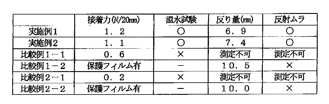
表1から明らかなように、本発明の実施例によれば、偏光子と位相差フィルムとの90°接着力を所定値以上とすることにより、温水浸漬試験において優れた耐久性が得られ、偏光子と位相差フィルムとを直接貼り合わせた状態で使用することができ、反りを抑制して、パネル面内での反射ムラを低減することができる。一方、比較例1−1および2−1から明らかなように、偏光子と位相差フィルムとの90°接着力が小さいと、有機ELパネルにおいて実用的に許容可能な耐久性が得られない。さらに、比較例1−2および2−2から明らかなように、偏光子と位相差フィルムとを直接貼り合わせた状態で使用することができない場合には、パネルの反り量が大きくなり、反射ムラが大きくなる。図2および図3に示すように、実施例1の有機ELパネルは比較例1−2の有機ELパネルに比べて反射ムラが顕著に抑制されていることがわかる。
20 保護フィルム
30 位相差フィルム
100 円偏光板
Claims (17)
- 偏光子と、該偏光子に直接接着された位相差フィルムとを備え、
該位相差フィルムの面内位相差が、Re(450)<Re(550)の関係を満たし、
該偏光子と該位相差フィルムとの90°接着力が1.0N/20mm以上であり、
有機ELパネルに用いられる、
円偏光板:
ここで、Re(450)およびRe(550)は、それぞれ、23℃における波長450nmおよび550nmで測定した面内位相差を表す。 - 前記位相差フィルムにコロナ処理またはプラズマ処理が施されている、請求項1に記載の円偏光板。
- 前記偏光子と前記位相差フィルムとの間に易接着層をさらに有する、請求項2に記載の円偏光板。
- 前記偏光子および前記位相差フィルムが長尺状であり、該位相差フィルムが35°≦θ≦55°の関係を満たす、請求項1に記載の円偏光板:
ここで、θは、該位相差フィルムの長尺方向と遅相軸とのなす角度である。 - 前記位相差フィルムが、脂肪族系モノマー由来の繰り返し単位を有する樹脂を含む、請求項1に記載の円偏光板。
- 前記位相差フィルムが、ポリカーボネート樹脂およびポリビニルアセタール樹脂からなる群から選択される少なくとも1つを含む、請求項1に記載の円偏光板。
- 前記ポリカーボネート樹脂が、ヒドロキシ基に結合した炭素原子の少なくとも1つのβ位またはγ位にエーテル性酸素原子を有するジヒドロキシ化合物に由来する構造単位を含む、請求項6に記載の円偏光板。
- 前記エーテル性酸素原子を有するジヒドロキシ化合物のエーテル性酸素原子が、下記式(1)で表される構造の酸素原子である、請求項7に記載の円偏光板。

- 前記エーテル性酸素原子を有するジヒドロキシ化合物が、下記式(2)で表されるジヒドロキシ化合物である、請求項7に記載の円偏光板。
- 前記エーテル性酸素原子を有するジヒドロキシ化合物が、下記式(3)で表されるジヒドロキシ化合物である、請求項7に記載の円偏光板。

- 前記エーテル性酸素原子を有するジヒドロキシ化合物が、環状エーテル構造を有する、請求項7に記載の円偏光板。
- 前記エーテル性酸素原子を有するジヒドロキシ化合物が、複数の環状構造を有する、請求項11に記載の円偏光板。
- 前記ポリカーボネート樹脂が、下記式(6)で表されるジヒドロキシ化合物、および下記式(7)で表されるジヒドロキシ化合物からなる群より選ばれた一種以上のジヒドロキシ化合物に由来する構造単位を含む、請求項7に記載の円偏光板。


- 前記ポリカーボネート樹脂が、芳香族ジカルボン酸に由来する構造単位を含む、請求項6に記載の円偏光板。
- 前記ポリカーボネート樹脂が、芳香族ジヒドロキシ化合物に由来する構造単位を含む、請求項6に記載の円偏光板。
- 前記芳香族ジヒドロキシ化合物が、2,2−ビス(4−ヒドロキシフェニル)プロパンである、請求項15に記載の円偏光板。
- 請求項1に記載の円偏光板を備える、有機ELパネル。
Priority Applications (4)
| Application Number | Priority Date | Filing Date | Title |
|---|---|---|---|
| US14/407,247 US9400345B2 (en) | 2012-06-29 | 2013-06-24 | Circular polarizing plate and organic electroluminescence panel |
| KR1020167022621A KR20160102323A (ko) | 2012-06-29 | 2013-06-24 | 원 편광판 및 유기 el 패널 |
| KR1020147036566A KR101921370B1 (ko) | 2012-06-29 | 2013-06-24 | 원 편광판 및 유기 el 패널 |
| CN201380034916.2A CN104412137B (zh) | 2012-06-29 | 2013-06-24 | 圆偏振板及有机el面板 |
Applications Claiming Priority (2)
| Application Number | Priority Date | Filing Date | Title |
|---|---|---|---|
| JP2012-146707 | 2012-06-29 | ||
| JP2012146707A JP6335422B2 (ja) | 2012-06-29 | 2012-06-29 | 円偏光板および有機elパネル |
Publications (1)
| Publication Number | Publication Date |
|---|---|
| WO2014003189A1 true WO2014003189A1 (ja) | 2014-01-03 |
Family
ID=49783323
Family Applications (1)
| Application Number | Title | Priority Date | Filing Date |
|---|---|---|---|
| PCT/JP2013/067956 Ceased WO2014003189A1 (ja) | 2012-06-29 | 2013-06-24 | 円偏光板および有機elパネル |
Country Status (6)
| Country | Link |
|---|---|
| US (1) | US9400345B2 (ja) |
| JP (1) | JP6335422B2 (ja) |
| KR (2) | KR20160102323A (ja) |
| CN (1) | CN104412137B (ja) |
| TW (1) | TWI607250B (ja) |
| WO (1) | WO2014003189A1 (ja) |
Cited By (1)
| Publication number | Priority date | Publication date | Assignee | Title |
|---|---|---|---|---|
| CN110651205A (zh) * | 2017-05-16 | 2020-01-03 | 日东电工株式会社 | 圆偏振膜、带粘合剂层的圆偏振膜及图像显示装置 |
Families Citing this family (6)
| Publication number | Priority date | Publication date | Assignee | Title |
|---|---|---|---|---|
| JP6904666B2 (ja) * | 2016-05-17 | 2021-07-21 | 日東電工株式会社 | 光学積層体 |
| KR102562288B1 (ko) | 2016-12-02 | 2023-08-02 | 삼성디스플레이 주식회사 | 표시 장치 |
| JP6412195B1 (ja) * | 2017-03-30 | 2018-10-24 | 日東電工株式会社 | 画像表示装置 |
| TW201942605A (zh) * | 2018-02-09 | 2019-11-01 | 日商住友化學股份有限公司 | 圓偏光板及光學顯示器件 |
| JP7305306B2 (ja) | 2018-03-30 | 2023-07-10 | 日東電工株式会社 | 円偏光板 |
| KR102747550B1 (ko) * | 2019-02-21 | 2025-01-02 | 삼성디스플레이 주식회사 | 편광 필름 및 이를 채용하는 표시 장치 |
Citations (11)
| Publication number | Priority date | Publication date | Assignee | Title |
|---|---|---|---|---|
| WO2000026705A1 (en) * | 1998-10-30 | 2000-05-11 | Teijin Limited | Phase difference film and optical device using it |
| JP2004144943A (ja) * | 2002-10-23 | 2004-05-20 | Fuji Photo Film Co Ltd | 円偏光板 |
| JP2006284703A (ja) * | 2005-03-31 | 2006-10-19 | Teijin Ltd | 積層位相差フィルム |
| JP2007108280A (ja) * | 2005-10-12 | 2007-04-26 | Teijin Chem Ltd | 位相差フィルム |
| JP2009098623A (ja) * | 2007-09-28 | 2009-05-07 | Nitto Denko Corp | 偏光板、その製造方法、光学フィルムおよび画像表示装置 |
| WO2009125717A1 (ja) * | 2008-04-07 | 2009-10-15 | 住友化学株式会社 | 複合偏光板およびこれを用いた液晶表示装置 |
| JP2010134232A (ja) * | 2008-12-05 | 2010-06-17 | Teijin Chem Ltd | 光学フィルム |
| JP4804589B1 (ja) * | 2010-09-03 | 2011-11-02 | 日東電工株式会社 | 偏光膜、偏光膜を含む光学フィルム積層体、及び、偏光膜を含む光学フィルム積層体の製造に用いるための延伸積層体、並びにそれらの製造方法、並びに偏光膜を有する有機el表示装置 |
| JP2011247967A (ja) * | 2010-05-25 | 2011-12-08 | Sumitomo Chemical Co Ltd | 複合光学フィルム及びその製造方法 |
| JP2012031369A (ja) * | 2009-11-17 | 2012-02-16 | Mitsubishi Chemicals Corp | ポリカーボネート樹脂 |
| WO2013039178A1 (ja) * | 2011-09-14 | 2013-03-21 | 三菱化学株式会社 | 位相差フィルム、並びにこれを用いた円偏光板及び画像表示装置 |
Family Cites Families (27)
| Publication number | Priority date | Publication date | Assignee | Title |
|---|---|---|---|---|
| JPH0527118A (ja) | 1991-07-17 | 1993-02-05 | Nitto Denko Corp | 位相差板及び円偏光板 |
| JP2001195003A (ja) * | 2000-01-11 | 2001-07-19 | Toyota Motor Corp | 表示素子 |
| JP4214705B2 (ja) * | 2002-03-20 | 2009-01-28 | 東レ株式会社 | 位相差フィルム及び円偏光板 |
| JP2004272202A (ja) * | 2003-02-21 | 2004-09-30 | Fuji Photo Film Co Ltd | 偏光板、円偏光板、楕円偏光板 |
| JP4780647B2 (ja) | 2004-12-02 | 2011-09-28 | 日東電工株式会社 | 光学フィルム用粘着剤、光学フィルム用粘着剤層およびその製造方法、粘着型光学フィルム、ならびに画像表示装置 |
| JP2006171235A (ja) | 2004-12-14 | 2006-06-29 | Nitto Denko Corp | 円偏光板、及び光学フィルム、及び画像表示装置 |
| JPWO2006112207A1 (ja) * | 2005-03-31 | 2008-12-04 | 株式会社日本触媒 | 偏光子保護フィルム、偏光板、および画像表示装置 |
| CN101454699B (zh) * | 2006-05-30 | 2010-11-10 | 新日本石油株式会社 | 椭圆偏振片、椭圆偏振片的制造方法、液晶显示装置及电致发光显示装置 |
| JP2007333946A (ja) * | 2006-06-14 | 2007-12-27 | Nitto Denko Corp | 偏光板のリワーク方法、偏光板、および画像表示装置 |
| JP4881105B2 (ja) * | 2006-08-24 | 2012-02-22 | 日東電工株式会社 | 光学フィルム、偏光板、および画像表示装置 |
| JP5268083B2 (ja) * | 2006-09-01 | 2013-08-21 | 日東電工株式会社 | 偏光子保護フィルム、偏光板、および画像表示装置 |
| JP5401032B2 (ja) * | 2006-12-15 | 2014-01-29 | 富士フイルム株式会社 | 光学異方性膜、輝度向上フィルム、位相差板および液晶表示装置 |
| US7906216B2 (en) | 2007-09-28 | 2011-03-15 | Nitto Denko Corporation | Polarizing plate, manufacturing method therefor, optical film and image display |
| TW201007228A (en) * | 2008-04-07 | 2010-02-16 | Sumitomo Chemical Co | Composite polarizing plate and liquid crystal display device using the same |
| KR101651306B1 (ko) | 2008-12-05 | 2016-08-25 | 테이진 카세이 가부시키가이샤 | 광학 필름 |
| JP2011081359A (ja) | 2009-09-09 | 2011-04-21 | Nitto Denko Corp | 偏光板の製造方法 |
| KR20130004899A (ko) * | 2010-03-03 | 2013-01-14 | 미쓰비시 쥬시 가부시끼가이샤 | 수지 시트 피복 금속 적층체 및 그 제조 방법 |
| JP5406784B2 (ja) * | 2010-04-26 | 2014-02-05 | 日東電工株式会社 | 水分散型粘着剤組成物およびその製造方法 |
| JP5399312B2 (ja) * | 2010-04-26 | 2014-01-29 | 日東電工株式会社 | 粘着シート |
| JP5478553B2 (ja) | 2010-09-03 | 2014-04-23 | 日東電工株式会社 | 連続ウェブ状光学フィルム積層体ロール及びその製造方法 |
| JP5474869B2 (ja) | 2010-09-03 | 2014-04-16 | 日東電工株式会社 | 偏光膜を有する積層体ストリップロールの製造方法 |
| JP5502023B2 (ja) | 2010-09-03 | 2014-05-28 | 日東電工株式会社 | 偏光膜を有する光学フィルム積層体ロールの製造方法 |
| JP5361941B2 (ja) | 2010-09-03 | 2013-12-04 | 日東電工株式会社 | 偏光膜を有する積層体ストリップロールの製造方法 |
| JP5511730B2 (ja) | 2010-09-03 | 2014-06-04 | 日東電工株式会社 | 光学的パネル組立体の連続的製造方法及び装置 |
| JP5701679B2 (ja) | 2010-09-03 | 2015-04-15 | 日東電工株式会社 | 矩形形状のパネルに偏光膜を有する光学フィルムを順次的に貼り付ける方法及び装置 |
| US9442233B2 (en) | 2010-12-06 | 2016-09-13 | Nitto Denko Corporation | Anti-reflection circularly polarizing plate for organic EL display and organic EL display |
| JP2013076982A (ja) | 2011-09-14 | 2013-04-25 | Mitsubishi Chemicals Corp | 位相差フィルム、並びにこれを用いた円偏光板及び画像表示装置 |
-
2012
- 2012-06-29 JP JP2012146707A patent/JP6335422B2/ja active Active
-
2013
- 2013-06-24 KR KR1020167022621A patent/KR20160102323A/ko not_active Ceased
- 2013-06-24 WO PCT/JP2013/067956 patent/WO2014003189A1/ja not_active Ceased
- 2013-06-24 KR KR1020147036566A patent/KR101921370B1/ko active Active
- 2013-06-24 CN CN201380034916.2A patent/CN104412137B/zh active Active
- 2013-06-24 US US14/407,247 patent/US9400345B2/en not_active Expired - Fee Related
- 2013-06-28 TW TW102123366A patent/TWI607250B/zh active
Patent Citations (11)
| Publication number | Priority date | Publication date | Assignee | Title |
|---|---|---|---|---|
| WO2000026705A1 (en) * | 1998-10-30 | 2000-05-11 | Teijin Limited | Phase difference film and optical device using it |
| JP2004144943A (ja) * | 2002-10-23 | 2004-05-20 | Fuji Photo Film Co Ltd | 円偏光板 |
| JP2006284703A (ja) * | 2005-03-31 | 2006-10-19 | Teijin Ltd | 積層位相差フィルム |
| JP2007108280A (ja) * | 2005-10-12 | 2007-04-26 | Teijin Chem Ltd | 位相差フィルム |
| JP2009098623A (ja) * | 2007-09-28 | 2009-05-07 | Nitto Denko Corp | 偏光板、その製造方法、光学フィルムおよび画像表示装置 |
| WO2009125717A1 (ja) * | 2008-04-07 | 2009-10-15 | 住友化学株式会社 | 複合偏光板およびこれを用いた液晶表示装置 |
| JP2010134232A (ja) * | 2008-12-05 | 2010-06-17 | Teijin Chem Ltd | 光学フィルム |
| JP2012031369A (ja) * | 2009-11-17 | 2012-02-16 | Mitsubishi Chemicals Corp | ポリカーボネート樹脂 |
| JP2011247967A (ja) * | 2010-05-25 | 2011-12-08 | Sumitomo Chemical Co Ltd | 複合光学フィルム及びその製造方法 |
| JP4804589B1 (ja) * | 2010-09-03 | 2011-11-02 | 日東電工株式会社 | 偏光膜、偏光膜を含む光学フィルム積層体、及び、偏光膜を含む光学フィルム積層体の製造に用いるための延伸積層体、並びにそれらの製造方法、並びに偏光膜を有する有機el表示装置 |
| WO2013039178A1 (ja) * | 2011-09-14 | 2013-03-21 | 三菱化学株式会社 | 位相差フィルム、並びにこれを用いた円偏光板及び画像表示装置 |
Cited By (1)
| Publication number | Priority date | Publication date | Assignee | Title |
|---|---|---|---|---|
| CN110651205A (zh) * | 2017-05-16 | 2020-01-03 | 日东电工株式会社 | 圆偏振膜、带粘合剂层的圆偏振膜及图像显示装置 |
Also Published As
| Publication number | Publication date |
|---|---|
| TW201407210A (zh) | 2014-02-16 |
| KR101921370B1 (ko) | 2018-11-22 |
| KR20150032846A (ko) | 2015-03-30 |
| US9400345B2 (en) | 2016-07-26 |
| CN104412137A (zh) | 2015-03-11 |
| CN104412137B (zh) | 2017-06-06 |
| JP2014010292A (ja) | 2014-01-20 |
| US20150160387A1 (en) | 2015-06-11 |
| KR20160102323A (ko) | 2016-08-29 |
| JP6335422B2 (ja) | 2018-05-30 |
| TWI607250B (zh) | 2017-12-01 |
Similar Documents
| Publication | Publication Date | Title |
|---|---|---|
| CN105487141B (zh) | 偏振板及有机el面板 | |
| JP6335422B2 (ja) | 円偏光板および有機elパネル | |
| JP6321435B2 (ja) | 偏光板および有機elパネル | |
| CN104428700B (zh) | 偏振板及有机el面板 | |
| JP2014010291A (ja) | 円偏光板および表示装置 | |
| CN104094142B (zh) | 相位差膜的制造方法 | |
| TWI875989B (zh) | 附相位差層及黏著劑層之偏光板、與使用該附相位差層及黏著劑層之偏光板的圖像顯示裝置 | |
| KR102731529B1 (ko) | 위상차 필름, 위상차층 부착 편광판 및 위상차 필름의 제조 방법 | |
| WO2018211738A1 (ja) | 円偏光板および有機elパネル | |
| JP2018151651A (ja) | 円偏光板および有機elパネル | |
| KR20240095215A (ko) | 위상차층 부착 편광판 및 화상 표시 장치 | |
| TWI812753B (zh) | 相位差膜、附相位差層之偏光板、及相位差膜之製造方法 | |
| CN115128725A (zh) | 带相位差层的偏振片以及使用了该带相位差层的偏振片的图像显示装置 | |
| TWI843516B (zh) | 附相位差層之偏光板及影像顯示裝置 |
Legal Events
| Date | Code | Title | Description |
|---|---|---|---|
| 121 | Ep: the epo has been informed by wipo that ep was designated in this application |
Ref document number: 13810552 Country of ref document: EP Kind code of ref document: A1 |
|
| WWE | Wipo information: entry into national phase |
Ref document number: 14407247 Country of ref document: US |
|
| ENP | Entry into the national phase |
Ref document number: 20147036566 Country of ref document: KR Kind code of ref document: A |
|
| NENP | Non-entry into the national phase |
Ref country code: DE |
|
| 122 | Ep: pct application non-entry in european phase |
Ref document number: 13810552 Country of ref document: EP Kind code of ref document: A1 |