WO2013157040A1 - 熱交換素子及び空気調和装置 - Google Patents
熱交換素子及び空気調和装置 Download PDFInfo
- Publication number
- WO2013157040A1 WO2013157040A1 PCT/JP2012/002681 JP2012002681W WO2013157040A1 WO 2013157040 A1 WO2013157040 A1 WO 2013157040A1 JP 2012002681 W JP2012002681 W JP 2012002681W WO 2013157040 A1 WO2013157040 A1 WO 2013157040A1
- Authority
- WO
- WIPO (PCT)
- Prior art keywords
- spacing
- heat exchange
- ribs
- exchange element
- rib
- Prior art date
Links
Images


Classifications
-
- F—MECHANICAL ENGINEERING; LIGHTING; HEATING; WEAPONS; BLASTING
- F28—HEAT EXCHANGE IN GENERAL
- F28F—DETAILS OF HEAT-EXCHANGE AND HEAT-TRANSFER APPARATUS, OF GENERAL APPLICATION
- F28F9/00—Casings; Header boxes; Auxiliary supports for elements; Auxiliary members within casings
-
- F—MECHANICAL ENGINEERING; LIGHTING; HEATING; WEAPONS; BLASTING
- F28—HEAT EXCHANGE IN GENERAL
- F28F—DETAILS OF HEAT-EXCHANGE AND HEAT-TRANSFER APPARATUS, OF GENERAL APPLICATION
- F28F3/00—Plate-like or laminated elements; Assemblies of plate-like or laminated elements
- F28F3/02—Elements or assemblies thereof with means for increasing heat-transfer area, e.g. with fins, with recesses, with corrugations
- F28F3/04—Elements or assemblies thereof with means for increasing heat-transfer area, e.g. with fins, with recesses, with corrugations the means being integral with the element
- F28F3/048—Elements or assemblies thereof with means for increasing heat-transfer area, e.g. with fins, with recesses, with corrugations the means being integral with the element in the form of ribs integral with the element or local variations in thickness of the element, e.g. grooves, microchannels
-
- F—MECHANICAL ENGINEERING; LIGHTING; HEATING; WEAPONS; BLASTING
- F28—HEAT EXCHANGE IN GENERAL
- F28D—HEAT-EXCHANGE APPARATUS, NOT PROVIDED FOR IN ANOTHER SUBCLASS, IN WHICH THE HEAT-EXCHANGE MEDIA DO NOT COME INTO DIRECT CONTACT
- F28D21/00—Heat-exchange apparatus not covered by any of the groups F28D1/00 - F28D20/00
- F28D21/0015—Heat and mass exchangers, e.g. with permeable walls
-
- F—MECHANICAL ENGINEERING; LIGHTING; HEATING; WEAPONS; BLASTING
- F28—HEAT EXCHANGE IN GENERAL
- F28D—HEAT-EXCHANGE APPARATUS, NOT PROVIDED FOR IN ANOTHER SUBCLASS, IN WHICH THE HEAT-EXCHANGE MEDIA DO NOT COME INTO DIRECT CONTACT
- F28D9/00—Heat-exchange apparatus having stationary plate-like or laminated conduit assemblies for both heat-exchange media, the media being in contact with different sides of a conduit wall
- F28D9/0031—Heat-exchange apparatus having stationary plate-like or laminated conduit assemblies for both heat-exchange media, the media being in contact with different sides of a conduit wall the conduits for one heat-exchange medium being formed by paired plates touching each other
- F28D9/0037—Heat-exchange apparatus having stationary plate-like or laminated conduit assemblies for both heat-exchange media, the media being in contact with different sides of a conduit wall the conduits for one heat-exchange medium being formed by paired plates touching each other the conduits for the other heat-exchange medium also being formed by paired plates touching each other
-
- F—MECHANICAL ENGINEERING; LIGHTING; HEATING; WEAPONS; BLASTING
- F28—HEAT EXCHANGE IN GENERAL
- F28F—DETAILS OF HEAT-EXCHANGE AND HEAT-TRANSFER APPARATUS, OF GENERAL APPLICATION
- F28F21/00—Constructions of heat-exchange apparatus characterised by the selection of particular materials
- F28F21/06—Constructions of heat-exchange apparatus characterised by the selection of particular materials of plastics material
-
- F—MECHANICAL ENGINEERING; LIGHTING; HEATING; WEAPONS; BLASTING
- F24—HEATING; RANGES; VENTILATING
- F24F—AIR-CONDITIONING; AIR-HUMIDIFICATION; VENTILATION; USE OF AIR CURRENTS FOR SCREENING
- F24F12/00—Use of energy recovery systems in air conditioning, ventilation or screening
- F24F12/001—Use of energy recovery systems in air conditioning, ventilation or screening with heat-exchange between supplied and exhausted air
- F24F12/006—Use of energy recovery systems in air conditioning, ventilation or screening with heat-exchange between supplied and exhausted air using an air-to-air heat exchanger
-
- F—MECHANICAL ENGINEERING; LIGHTING; HEATING; WEAPONS; BLASTING
- F28—HEAT EXCHANGE IN GENERAL
- F28F—DETAILS OF HEAT-EXCHANGE AND HEAT-TRANSFER APPARATUS, OF GENERAL APPLICATION
- F28F2275/00—Fastening; Joining
- F28F2275/02—Fastening; Joining by using bonding materials; by embedding elements in particular materials
- F28F2275/025—Fastening; Joining by using bonding materials; by embedding elements in particular materials by using adhesives
-
- Y—GENERAL TAGGING OF NEW TECHNOLOGICAL DEVELOPMENTS; GENERAL TAGGING OF CROSS-SECTIONAL TECHNOLOGIES SPANNING OVER SEVERAL SECTIONS OF THE IPC; TECHNICAL SUBJECTS COVERED BY FORMER USPC CROSS-REFERENCE ART COLLECTIONS [XRACs] AND DIGESTS
- Y02—TECHNOLOGIES OR APPLICATIONS FOR MITIGATION OR ADAPTATION AGAINST CLIMATE CHANGE
- Y02B—CLIMATE CHANGE MITIGATION TECHNOLOGIES RELATED TO BUILDINGS, e.g. HOUSING, HOUSE APPLIANCES OR RELATED END-USER APPLICATIONS
- Y02B30/00—Energy efficient heating, ventilation or air conditioning [HVAC]
- Y02B30/56—Heat recovery units
Definitions
- the present invention relates to a heat exchange element having a laminated structure for exchanging heat and humidity between fluids in an air conditioner that performs air supply from the outside to the room and exhaust from the room to the outside at the same time.
- Conventional heat exchange elements employ a structure in which a partition member having gas shielding properties, heat transfer properties, and moisture permeability is sandwiched between interval holding members having a corrugated cross section, and stacked on a plurality of layers at predetermined intervals.
- the partition member is a rectangular flat plate
- the spacing member is a corrugated plate having a triangular cross-sectional shape. The spacing member is reversed 90 degrees between the partition members for each corrugated direction.
- Patent Document 1 There are some in which two-way fluid passages that are alternately stacked and pass the primary air flow and the secondary air flow are formed between the respective layers.
- the air passage blockage due to the deflection of the partition member can be alleviated by the interval holding member by narrowing the arrangement interval of the interval holding member. Furthermore, although it is possible to prevent an increase in ventilation resistance due to the collapse of the cross-sectional shape of the ventilation path, the effective area of the ventilation path is reduced, resulting in an increase in ventilation resistance. Further, if the arrangement interval of the interval holding member is narrowed, the portion where the interval holding member comes into contact with the upper and lower partition members at the time of stacking increases, so the total heat exchange efficiency is improved by reducing the heat transfer area and moisture permeable area. There was a problem that it would decrease.
- the present invention has been made to solve the above-described conventional problems, and even when a dense and high-density material for improving the total heat exchange efficiency is used for the partition member, the deflection of the partition member due to temperature and humidity changes.
- the purpose of the present invention is to obtain a heat exchange element that can reduce the deterioration of the ventilation resistance by suppressing the airflow and can improve the total heat exchange efficiency by suppressing the decrease in the heat transfer area due to the increase in the spacing member. .
- the present invention includes a unit member formed of a partition member having heat conductivity and moisture permeability and a spacing member that holds the partition member at a predetermined interval, and passes through the surface side of the partition member.
- the spacing member is formed of the partition member.
- a first shielding rib provided in parallel with the direction in which the primary airflow flows on both sides of the surface, and a second shielding rib provided in parallel with the direction in which the secondary airflow flows on both sides of the back surface of the partition member, respectively.
- a first spacing rib that is connected to the second shielding rib and is provided in parallel at predetermined intervals between the first shielding ribs, and is connected to the first shielding rib and between the second shielding ribs. Are set in parallel at predetermined intervals.
- the first deflection rib is connected to the second spacing rib and the second shielding rib, and has a lower height than the first spacing rib provided in parallel between the first spacing ribs at predetermined intervals.
- a rib and a second deflection suppression rib connected to the first shielding rib and having a height lower than that of the second spacing rib provided in parallel between the second spacing ribs at predetermined intervals. It is characterized by that.
- the deflection member is formed with a deflection suppressing rib different from the spacing rib between the spacing ribs, the air path is blocked even when the partitioning member expands and contracts due to a change in the temperature and humidity environment. Can be suppressed, and an increase in pressure loss due to deterioration in ventilation resistance can be reduced.
- the deflection suppressing rib is not in contact with other layers (upper and lower layers at the time of lamination) because the rib height is sufficiently lower than the spacing rib, and the heat transfer area and moisture permeability area for each layer of the partition member As a result, the humidity exchange efficiency and the total heat exchange efficiency can be improved.
- FIG. 4 is a schematic diagram of a four-view diagram of one unit constituent member according to the first embodiment of the present invention.
- interval rib concerning Embodiment 1 of this invention contact
- interval rib concerning Embodiment 1 of this invention contact
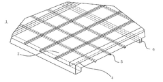
- FIG. 1 is a perspective view of a heat exchange element according to Embodiment 1 of the present invention
- FIG. 2 is a perspective view of one layer of a unit constituent member according to Embodiment 1 of the present invention
- FIG. It is the C section enlarged view of FIG. 2 which is the unit structural member 1 layer concerning Embodiment 1 of invention.
- the heat exchange element 1 in Embodiment 1 of this invention is the partition member 2 which has heat conductivity, moisture permeability, and shielding which performs heat exchange of the air which passes up and down, and this Unit constituent members 7 formed by integrally molding the spacing member 3 that holds the partition member 2 at a predetermined interval are inverted 90 degrees for each sheet and alternately stacked, and pass through one side of the partition member 2.
- the primary airflow A and the secondary airflow B passing through the other side of the partition member 2 exchange heat and humidity via the partition member 2. Details of each element constituting the heat exchange element 1 will be described below.
- the partition member 2 serves as a medium through which heat and moisture are transmitted when heat and humidity are exchanged between the primary airflow A and the secondary airflow B.
- the temperature difference (or water vapor partial pressure difference) of the heat (or water vapor) in the air flow on the high temperature side (or high humidity side) is utilized on both sides of the partition member 2 to The temperature (humidity) is exchanged by shifting from the (high humidity side) to the low temperature side (or low humidity side) via the partition member 2.
- the partition member 2 must be able to prevent the primary air stream A and the secondary air stream B from being mixed, and to suppress the transfer of carbon dioxide, odor components, and the like between the air streams.
- the partition member 2 is a dense and high-density material having a density of 0.95 [g / cm 2 ] or more and an air permeability resistance (JIS P8628) of 5000 seconds / 100 cc or more. What has moisture permeability is good.
- the material of the partition member 2 is made from Japanese paper, flame retardant paper containing inorganic additives, other specially processed paper, paper mixed with resin and pulp, etc.
- Moisture permeable membranes that have been treated with chemicals to impart functionality such as flame retardancy, polyurethane-based resins containing oxyethylene groups with moisture permeability, polyester-based resins containing oxyethylene groups, and terminal or side chains
- a porous sheet (nonwoven fabric, expanded PTFE membrane, etc.) bonded to a water-insoluble hydrophilic polymer thin film formed of a resin containing a sulfonic acid group, amino group, hydroxyl group, carboxyl group, etc. by heat or an adhesive.
- a sensible heat exchanger it is a resin sheet or resin film of polystyrene-based ABS, AS, PS, polyolefin-based PP, PE, etc. having only heat transfer and gas shielding properties.
- cellulose fiber Pulp
- paper is thoroughly beaten to fibrillate the fiber, and after that, paper is made and calendered (squeezed) with a super calendar.
- the density of these partition members 2 is normal paper (thickness of about 100 to 150 ⁇ m, density of about 0.6, excluding those containing additives such as inorganic components) Compared to about 0.8 to 0.8 g / cm 3 ), the thickness is about 20 to 60 ⁇ m, and the density is 0.9 g / cm 3 or more to nearly 1 g / cm 3 or larger.
- FIG. 4 is a schematic diagram of the unit constituent member 7 according to the first embodiment of the present invention, a four-layer view of one layer.
- the spacing member 3 suppresses deflection due to expansion of the partition member 2, and constitutes a portion other than the partition member 2 of the heat exchange element 1.
- the spacing member 3 constitutes an outer frame of the heat exchange element 1, and in order to prevent air leakage from both ends of the heat exchange element 1, shielding is provided at both ends in parallel with the airflow direction.
- a plurality of deflection ribs 5 are provided between the spacing ribs 6 at predetermined intervals in parallel with the spacing ribs 6 and suppress the air passage blockage caused by the deflection of the partition member 2.
- the deflection suppressing rib 5 is formed to be lower and narrower than the spacing holding rib 6, and these shielding rib 4, deflection suppressing rib 5, and spacing rib 6 are arranged on both the front and back sides of the partition member 2. It is formed 90 degrees behind the back.
- the deflection suppressing rib 5 has a thin and thin shape so as to suppress the pressure loss of the ventilation as much as possible and do not hinder the heat transfer area and moisture permeability area of the partition member 2. Accordingly, it is desirable that the deflection suppressing rib 5 has a low rib height and a thin rib width.
- the rib height of the deflection suppressing rib 5 is preferably less than 1 ⁇ 2 of the rib height of the spacing rib 6 so as not to interfere (contact) with the upper and lower deflection suppressing ribs 5 at the time of lamination.
- the rib width of the deflection suppressing rib 5 becomes an obstructive factor for the heat transfer area and the moisture permeable area, it is desired that the bending suppression rib 5 be as thin as possible by molding.
- the heat exchange elements 1 are stacked by being shifted by 90 degrees will be described with reference to FIGS.
- FIG. 5 is a schematic view in which unit component members 7 having a configuration in which the tips of the spacing ribs 6 according to the first embodiment do not come into contact with each other at the time of stacking are stacked.
- the heat exchange element 1 shown in FIG. 5 (focusing only on the three layers) is configured by stacking unit constituent members 7 having the same structure (in order from the top, the upper stage is 7D, the interruption is 7E, and the lower stage is 7F). ing.
- the shielding rib 4D of the upper unit component member 7D and the shielding rib 4E of the middle unit component member 7E are in contact with each other on the side surface.
- the top surface portion of the shielding rib 4D of the upper unit component member 7D is in contact with the partition member 2E of the middle unit component member 7E, and the top surface of the shielding rib 4E of the middle unit component member 7E is the upper unit component member 7D. This is in contact with the partition member 2D.
- the spacing rib 6D of the upper unit component member 7D and the spacing rib 6E of the middle unit component member 7E are in contact with each other on the side surface.
- the top surface portion of the spacing rib 6D of the upper unit component member 7D is in contact with the partition member 2E of the middle unit component member 7E, and the top surface of the spacing rib 6E of the middle unit component member 7E is the upper unit component member 7D.
- a space surrounded by the shielding ribs 4D and 4E, the spacing ribs 6D and 6E, and the spacing ribs 6D and 6E is a ventilation path.
- Deflection suppression ribs 5D and 5E are provided in the ventilation path in order to prevent the cutting members 2D and 2E from bending.
- the deflection suppressing rib 5D of the upper unit component member 7D exists right above the deflection suppression rib 5E of the middle unit component member 7E, but it may not be directly above but may be shifted.
- the shielding ribs 4D and 4E also function as spacing ribs 6D and 6E that maintain the spacing between the partition members 2D and 2E in the stacking direction when stacked.
- the unit constituting member 7 is not provided with the shielding ribs 4D and 4E, but is provided with the spacing ribs 6D and 6E and the deflection suppressing ribs 5D and 5E, and the spacing ribs 6D and 6E at both ends are kept air shielded by a sealing material or the like. It may be.
- the spacing rib 6 ⁇ / b> D and the spacing rib 6 ⁇ / b> E are in contact with each other on the side surface.
- the partition members 2D and 2E Since the rib widths of the deflection suppressing ribs 5D and 5E are as narrow as possible, the partition members 2D and 2E have little influence on the heat transfer area and moisture permeable area for each layer, resulting in humidity exchange efficiency and total heat exchange efficiency. Can be improved. Furthermore, since the deflection suppressing ribs 5D and 5E can also play the role of fins, the fin effect also has the effect of improving the temperature exchange efficiency as a result. By making the deflection suppressing ribs 5D and 5E perpendicular to each other on the front and back sides of the partitioning members 2D and 2E, the respective expansion amounts of the partitioning members 2D and 2E surrounded by the deflection suppressing rib 5 in the width direction and the length direction of the paper.
- the heat exchange element 1 can be formed by integral molding by using a material that is difficult to join and that cannot be used with large deflection as the partition members 2D and 2E.
- FIG. 6 is a schematic diagram in which unit component members 7 having a configuration in which the tips of the spacing ribs 6 according to the first embodiment of the present invention are partly in contact with each other when stacked are stacked.
- the heat exchange element 1 shown in FIG. 6 (focusing on only three layers) is configured by laminating unit constituent members 7 having the same structure (in order from the top, the upper stage is 7G, the interruption is 7H, and the lower stage is 7I). ing.
- the shielding rib 4G of the upper unit component member 7G and the shielding rib 4H of the middle unit component member 7H are in contact with each other on the side surface.
- the top surface portion of the shielding rib 4G of the upper unit component member 7G contacts the partition member 2H of the middle unit component member 7H
- the top surface of the shielding rib 4H of the middle unit component member 7H is the upper unit component member 7G. Is in contact with the partition member 2G.
- the spacing rib 6D of the upper unit component member 7D and the spacing rib 6E of the middle unit component member 7E are in contact with each other at the side surface
- the top surface portion of the spacing rib 6D of the upper unit component member 7D is the middle unit component member.
- the top surface of the spacing rib 6E of the middle unit component member 7E is in contact with the partition member 2D of the upper unit component member 7D, but in FIG.
- all the spacing ribs 6G, 6H does not have this structure, and some of the spacing ribs 6G and 6H are in contact with each other at their tips.
- a space surrounded by the shielding ribs 4G and 4H, the spacing ribs 6G and 6H, and the spacing ribs 6G and 6H is a ventilation path.
- Deflection suppression ribs 5G and 5H are provided in the ventilation path in order to prevent the partition members 2G and 2H from bending.
- the deflection suppressing rib 5G of the upper unit component member 7G exists right above the deflection suppression rib 5H of the middle unit component member 7H, but may not be directly above but may be shifted.
- the shielding ribs 4G and 4H also function as spacing ribs 6G and 6H that hold the spacing between the partition members 2G and 2H in the stacking direction when stacked.
- the unit constituting member 7 is not provided with the shielding ribs 4G and 4H, but is provided with the spacing ribs 6G and 6H and the deflection suppressing ribs 5G and 5H, and the spacing ribs 6G and 6H at both ends are kept air shielded by a sealing material or the like. It may be.
- the spacing rib 6G and the spacing rib 6H are in contact with each other on the side surface, but need not be contacted on the side surface.
- the rib width of the deflection suppressing ribs 5G and 5H is as narrow as possible, there is little influence on the heat transfer area and the moisture permeable area for each partition member 2G and 2H1 layer. As a result, the humidity exchange efficiency and the total heat exchange efficiency are improved. Can be improved. Moreover, since the deflection suppressing ribs 5G and 5H can also play the role of fins, the fin effect also has the effect of improving the temperature exchange efficiency as a result.
- the deflection suppressing ribs 5G and 5H orthogonal to each other on the front and back of the partitioning members 2G and 2H, the width direction and the lengthwise direction of the paper of the partitioning members 2G and 2H surrounded by the deflection suppressing ribs 5G and 5H, respectively. Since the amount of elongation is reduced and the deflection rate in the region of the partition members 2G and 2H constrained by the deflection suppressing ribs 5G and 5H is reduced, pressure loss due to deterioration of the ventilation resistance is suppressed.
- the spacing ribs 6G and 6H are in contact with each other at the tips of the spacing ribs 6G and 6H, it is possible to secure the area of the air path as compared with the case where all of the spacing ribs 6G and 6H are in contact with each other. It is possible to suppress pressure loss due to deterioration. Further, since the amount of expansion / contraction is large so far, there is an effect that the heat exchange element 1 can be formed by integral molding by using a material that has been difficult to be joined in the past and that cannot be used with a large amount of deflection as the partition members 2D and 2E.
- FIG. 7 is a schematic diagram in which unit constituent members having a configuration in which the tips of the spacing ribs 6 according to the first embodiment of the present invention are all in contact with each other at the time of stacking.
- the heat exchange element 1 shown in FIG. 7 (focusing on only three layers) is configured by laminating unit constituent members 7 having the same structure (in order from the top, the upper stage is 7J, the interruption is 7K, and the lower stage is 7L). ing.
- the shielding rib 4J of the upper unit component member 7J and the shielding rib 4K of the middle unit component member 7K are in contact with each other at the top surface, and the spacing rib 6J of the upper unit component member 7J and the spacing rib 6K of the middle unit component member 7K.
- a space surrounded by the shielding ribs 4J and 4K, the spacing ribs 6J and 6K, and the spacing ribs 6J and 6K is a ventilation path.
- Deflection suppression ribs 5J and 5K are provided in the ventilation path in order to prevent the partition members 2J and 2K from bending.
- the deflection suppressing rib 5J of the upper unit component member 7J is present directly above the deflection suppressing rib 5K of the middle unit component member 7K, but may not be directly above but may be shifted.
- the shielding ribs 4J and 4K also function as spacing ribs 6G and 6H that hold the spacing between the partition members 2J and 2K in the stacking direction when stacked.
- the unit constituting member 7 is not provided with the shielding ribs 4J and 4K, but is provided with the spacing ribs 6G and 6H and the deflection suppressing ribs 5J and 5K, and the spacing ribs 6G and 6H at both ends are sealed with a sealing material or the like. It may be.
- the rib width of the deflection suppressing ribs 5J and 5K is as narrow as possible, there is little influence on the heat transfer area and moisture permeable area for each partition member 2J and 2K1 layer, and as a result, humidity exchange efficiency and total heat exchange efficiency are improved. Can be improved. Further, since the deflection suppressing ribs 5J and 5K can also play a role of fins, the fin effect also has an effect of improving the temperature exchange efficiency as a result.
- each of the paper in the width direction and the length direction of the partitioning members 2J and 2K surrounded by the deflection suppressing ribs 5J and 5K Since the amount of elongation is reduced and the deflection rate in the region of the partition members 2J and 2K constrained by the deflection suppression ribs 5J and 5K is also reduced, pressure loss due to deterioration of the ventilation resistance is suppressed.
- the spacing ribs 6J and 6K are in contact with each other at the tips of the spacing ribs 6J and 6K, it is possible to secure an area of the air path rather than in contact with each other on the side surface. Pressure loss due to deterioration can be suppressed. Furthermore, since the shielding ribs 4J and 4K are in contact with each other at their tips, the length of one side constituting the air passage is doubled, and the area of the air passage can be secured greatly. Pressure loss due to resistance deterioration can be suppressed.
- the heat exchange element 1 can be formed by integral molding by using as the partition members 2J and 2K a material that has been difficult to join and can not be used with a large amount of deflection.
- the interval holding member 3 including the shielding rib 4, the deflection suppressing rib 5, and the interval rib 6 is generally square (when the primary and secondary air currents are orthogonal) or a parallelogram (also the air currents are obliquely crossed).
- the shielding rib 4 needs to be designed to have a wider rib width than the spacing rib 6 in order to increase the reliability of the partition member 2 against air leakage.
- the rib width be as narrow as possible. The amount of resin used is also reduced due to the narrow rib width.
- the resin used for the spacing member 3 is polypropylene (PP), acrylonitrile-butadiene-styrene (ABS), polystyrene (PS), acrylonitrile-styrene (AS), polycarbonate (PC), and other general resins in a desired shape. Any material that can be molded may be used. Since the ribs are formed of resin in this way, deformation of the spacing member 3 due to a change in humidity such as the corrugated shape of FIG. 1 in which paper is used as the spacing member 3 can be suppressed. Can be achieved. In addition, these resins are made flame retardant by adding a flame retardant, and inorganic components are added to improve dimensional stability and strength.
- Heat exchange element 2 ⁇ 2D ⁇ 2E ⁇ 2G ⁇ 2H ⁇ 2J ⁇ 2K Partition member 3
- Spacing member 4 ⁇ 4D ⁇ 4E ⁇ 4G ⁇ 4H ⁇ 4J ⁇ 4K Shielding ribs 5 ⁇ 5D ⁇ 5E ⁇ 5G ⁇ 5H ⁇ 5J ⁇ 5K Deflection suppression rib 6, 6D, 6E, 6G, 6H, 6J, 6K Spacing rib 7, 7D, 7E, 7F, 7G, 7H, 7I, 7J, 7K, 7L Unit component A Primary airflow B Secondary airflow
Landscapes
- Engineering & Computer Science (AREA)
- Physics & Mathematics (AREA)
- Thermal Sciences (AREA)
- Mechanical Engineering (AREA)
- General Engineering & Computer Science (AREA)
- Heat-Exchange Devices With Radiators And Conduit Assemblies (AREA)
Priority Applications (9)
| Application Number | Priority Date | Filing Date | Title |
|---|---|---|---|
| PCT/JP2012/002681 WO2013157040A1 (ja) | 2012-04-18 | 2012-04-18 | 熱交換素子及び空気調和装置 |
| EP12874435.6A EP2851642B1 (en) | 2012-04-18 | 2012-06-13 | Heat-exchange element and air conditioner |
| US14/385,286 US9903669B2 (en) | 2012-04-18 | 2012-06-13 | Heat exchange element and air conditioner |
| KR1020147028751A KR20140137433A (ko) | 2012-04-18 | 2012-06-13 | 열교환 소자 및 공기조화 장치 |
| PL12874435T PL2851642T3 (pl) | 2012-04-18 | 2012-06-13 | Element wymiany ciepła i klimatyzator |
| PCT/JP2012/003840 WO2013157055A1 (ja) | 2012-04-18 | 2012-06-13 | 熱交換素子及び空気調和装置 |
| JP2014510972A JP5781221B2 (ja) | 2012-04-18 | 2012-06-13 | 熱交換素子及び空気調和装置 |
| CN201280072417.8A CN104246411B (zh) | 2012-04-18 | 2012-06-13 | 热交换元件及空气调节装置 |
| TW101126561A TWI525294B (zh) | 2012-04-18 | 2012-07-24 | Heat exchange components and air conditioning devices |
Applications Claiming Priority (1)
| Application Number | Priority Date | Filing Date | Title |
|---|---|---|---|
| PCT/JP2012/002681 WO2013157040A1 (ja) | 2012-04-18 | 2012-04-18 | 熱交換素子及び空気調和装置 |
Publications (1)
| Publication Number | Publication Date |
|---|---|
| WO2013157040A1 true WO2013157040A1 (ja) | 2013-10-24 |
Family
ID=49383037
Family Applications (2)
| Application Number | Title | Priority Date | Filing Date |
|---|---|---|---|
| PCT/JP2012/002681 WO2013157040A1 (ja) | 2012-04-18 | 2012-04-18 | 熱交換素子及び空気調和装置 |
| PCT/JP2012/003840 WO2013157055A1 (ja) | 2012-04-18 | 2012-06-13 | 熱交換素子及び空気調和装置 |
Family Applications After (1)
| Application Number | Title | Priority Date | Filing Date |
|---|---|---|---|
| PCT/JP2012/003840 WO2013157055A1 (ja) | 2012-04-18 | 2012-06-13 | 熱交換素子及び空気調和装置 |
Country Status (7)
| Country | Link |
|---|---|
| US (1) | US9903669B2 (zh) |
| EP (1) | EP2851642B1 (zh) |
| KR (1) | KR20140137433A (zh) |
| CN (1) | CN104246411B (zh) |
| PL (1) | PL2851642T3 (zh) |
| TW (1) | TWI525294B (zh) |
| WO (2) | WO2013157040A1 (zh) |
Cited By (2)
| Publication number | Priority date | Publication date | Assignee | Title |
|---|---|---|---|---|
| US9664452B2 (en) | 2012-04-20 | 2017-05-30 | Mitsubishi Electric Corporation | Heat exchange element |
| WO2022186302A1 (ja) * | 2021-03-03 | 2022-09-09 | ダイキン工業株式会社 | 熱交換器及び空気処理装置 |
Families Citing this family (19)
| Publication number | Priority date | Publication date | Assignee | Title |
|---|---|---|---|---|
| CN103890528B (zh) | 2011-10-26 | 2017-05-24 | 三菱电机株式会社 | 全热交换元件及其制造方法 |
| CN107208985B (zh) * | 2014-12-18 | 2019-07-26 | 迈科电气设备厂有限公司 | 换热器和具有换热器的空气技术设备 |
| FR3036179A1 (fr) * | 2015-05-12 | 2016-11-18 | Tmw | Echangeur thermique moule en deux parties et procede de fabrication d’un tel echangeur |
| JP2017090026A (ja) * | 2015-11-17 | 2017-05-25 | 株式会社東芝 | 熱交換器及び換気装置 |
| KR102511542B1 (ko) * | 2015-12-02 | 2023-03-20 | 삼성디스플레이 주식회사 | 회로 기판 및 이를 포함하는 표시장치 |
| CN106052464A (zh) * | 2016-06-17 | 2016-10-26 | 安徽天祥空调科技有限公司 | 一种平行流蒸发器积液器主片及其制备工艺 |
| KR102628091B1 (ko) * | 2016-09-28 | 2024-01-23 | 엘지전자 주식회사 | 디스플레이 장치 |
| GB2561894B (en) | 2017-04-28 | 2019-10-16 | Amscreen Group Ltd | Environment control in electronic displays |
| GB2565997B (en) | 2017-04-28 | 2019-10-16 | Amscreen Group Ltd | Crossflow heat-exchangers |
| GB2561895B (en) * | 2017-04-28 | 2019-10-16 | Amscreen Group Ltd | Cooling of electronic displays |
| GB2561893B (en) | 2017-04-28 | 2020-04-15 | Amscreen Group Ltd | Environment control in electronic apparatus |
| GB201706770D0 (en) | 2017-04-28 | 2017-06-14 | Amscreen Group Ltd | Control of electronic displays |
| CN107504833A (zh) * | 2017-09-20 | 2017-12-22 | 台州德备环境设备科技有限公司 | 热交换芯片及热交换芯 |
| US10113767B1 (en) | 2018-02-01 | 2018-10-30 | Berg Companies, Inc. | Air handling unit |
| CN108709257B (zh) * | 2018-06-15 | 2023-12-19 | 广东芬尼克兹节能设备有限公司 | 一种除湿机 |
| CN111412763B (zh) * | 2018-07-20 | 2021-07-23 | 山东大学 | 一种汽液两相流的换热管内部尺寸的设计方法 |
| JP2020051655A (ja) * | 2018-09-26 | 2020-04-02 | パナソニックIpマネジメント株式会社 | 熱交換素子及びそれを用いた熱交換形換気装置 |
| US11306979B2 (en) * | 2018-12-05 | 2022-04-19 | Hamilton Sundstrand Corporation | Heat exchanger riblet and turbulator features for improved manufacturability and performance |
| US11686537B2 (en) * | 2021-04-06 | 2023-06-27 | General Electric Company | Heat exchangers and methods of manufacturing the same |
Citations (7)
| Publication number | Priority date | Publication date | Assignee | Title |
|---|---|---|---|---|
| JPH03279793A (ja) * | 1990-03-28 | 1991-12-10 | Matsushita Electric Ind Co Ltd | 全熱交換素子 |
| JPH08110076A (ja) * | 1994-10-11 | 1996-04-30 | Matsushita Seiko Co Ltd | 熱交換素子 |
| JPH08178577A (ja) * | 1994-12-26 | 1996-07-12 | Daikin Ind Ltd | 熱交換エレメント |
| JPH10506178A (ja) * | 1994-09-27 | 1998-06-16 | ハドワコ リミテッド オーワイ | 熱交換器 |
| JP2000502788A (ja) * | 1995-12-29 | 2000-03-07 | ランテック・プロダクツ・インコーポレーテッド | サーマルベッド及び触媒ベッド用のチャネルを有するセラミックパッキング |
| JP2007285691A (ja) * | 2006-03-22 | 2007-11-01 | Matsushita Electric Ind Co Ltd | 熱交換器 |
| WO2008126372A1 (ja) * | 2007-03-30 | 2008-10-23 | Panasonic Corporation | 熱交換素子 |
Family Cites Families (22)
| Publication number | Priority date | Publication date | Assignee | Title |
|---|---|---|---|---|
| JPS4719990B1 (zh) | 1969-03-20 | 1972-06-07 | ||
| JPS5579996A (en) * | 1978-12-14 | 1980-06-16 | Teijin Ltd | Wet heat exchanger |
| AU624662B2 (en) * | 1988-12-12 | 1992-06-18 | Vulcan Australia Limited | Heat exchanger |
| JPH04313694A (ja) * | 1991-04-10 | 1992-11-05 | Matsushita Electric Ind Co Ltd | 熱交換素子 |
| JPH07208891A (ja) | 1994-01-14 | 1995-08-11 | Toshiba Corp | 熱交換素子 |
| JP2690272B2 (ja) | 1994-08-04 | 1997-12-10 | 松下精工株式会社 | 熱交換素子 |
| JPH08145588A (ja) | 1994-11-18 | 1996-06-07 | Matsushita Seiko Co Ltd | 熱交換素子 |
| JPH09152291A (ja) | 1995-11-29 | 1997-06-10 | Matsushita Seiko Co Ltd | 熱交換素子 |
| US6145588A (en) * | 1998-08-03 | 2000-11-14 | Xetex, Inc. | Air-to-air heat and moisture exchanger incorporating a composite material for separating moisture from air technical field |
| US6841601B2 (en) * | 2001-03-13 | 2005-01-11 | Dais-Analytic Corporation | Crosslinked polymer electrolyte membranes for heat and moisture exchange devices |
| JP4094318B2 (ja) | 2002-03-28 | 2008-06-04 | 松下エコシステムズ株式会社 | 熱交換膜および熱交換素子 |
| JP4507995B2 (ja) * | 2005-06-14 | 2010-07-21 | パナソニック株式会社 | 熱交換機器 |
| US7320361B2 (en) * | 2005-10-28 | 2008-01-22 | Mitsubishi Denki Kabushiki Kaisha | Heat exchanger |
| JP4770534B2 (ja) | 2006-03-22 | 2011-09-14 | パナソニック株式会社 | 熱交換器 |
| US8002023B2 (en) * | 2006-03-22 | 2011-08-23 | Panasonic Corporation | Heat exchanger and its manufacturing method |
| JP4765706B2 (ja) * | 2006-03-22 | 2011-09-07 | パナソニック株式会社 | 熱交換器の製造方法 |
| JP4816517B2 (ja) | 2006-09-28 | 2011-11-16 | パナソニック株式会社 | 熱交換素子 |
| CN101233381B (zh) * | 2006-10-03 | 2010-06-09 | 三菱电机株式会社 | 总热交换元件及总热交换器 |
| DE102009038154B4 (de) | 2009-08-20 | 2014-01-09 | Continental Automotive Gmbh | Temperiereinheit und Batteriesystem umfassend eine solche Temperiereinheit |
| US9429366B2 (en) * | 2010-09-29 | 2016-08-30 | Kraton Polymers U.S. Llc | Energy recovery ventilation sulfonated block copolymer laminate membrane |
| US20140014289A1 (en) * | 2012-07-11 | 2014-01-16 | Kraton Polymers U.S. Llc | Enhanced-efficiency energy recovery ventilation core |
| US20140262125A1 (en) * | 2013-03-14 | 2014-09-18 | Venmar Ces, Inc. | Energy exchange assembly with microporous membrane |
-
2012
- 2012-04-18 WO PCT/JP2012/002681 patent/WO2013157040A1/ja active Application Filing
- 2012-06-13 PL PL12874435T patent/PL2851642T3/pl unknown
- 2012-06-13 WO PCT/JP2012/003840 patent/WO2013157055A1/ja active Application Filing
- 2012-06-13 CN CN201280072417.8A patent/CN104246411B/zh active Active
- 2012-06-13 KR KR1020147028751A patent/KR20140137433A/ko active Search and Examination
- 2012-06-13 US US14/385,286 patent/US9903669B2/en active Active
- 2012-06-13 EP EP12874435.6A patent/EP2851642B1/en active Active
- 2012-07-24 TW TW101126561A patent/TWI525294B/zh active
Patent Citations (7)
| Publication number | Priority date | Publication date | Assignee | Title |
|---|---|---|---|---|
| JPH03279793A (ja) * | 1990-03-28 | 1991-12-10 | Matsushita Electric Ind Co Ltd | 全熱交換素子 |
| JPH10506178A (ja) * | 1994-09-27 | 1998-06-16 | ハドワコ リミテッド オーワイ | 熱交換器 |
| JPH08110076A (ja) * | 1994-10-11 | 1996-04-30 | Matsushita Seiko Co Ltd | 熱交換素子 |
| JPH08178577A (ja) * | 1994-12-26 | 1996-07-12 | Daikin Ind Ltd | 熱交換エレメント |
| JP2000502788A (ja) * | 1995-12-29 | 2000-03-07 | ランテック・プロダクツ・インコーポレーテッド | サーマルベッド及び触媒ベッド用のチャネルを有するセラミックパッキング |
| JP2007285691A (ja) * | 2006-03-22 | 2007-11-01 | Matsushita Electric Ind Co Ltd | 熱交換器 |
| WO2008126372A1 (ja) * | 2007-03-30 | 2008-10-23 | Panasonic Corporation | 熱交換素子 |
Cited By (3)
| Publication number | Priority date | Publication date | Assignee | Title |
|---|---|---|---|---|
| US9664452B2 (en) | 2012-04-20 | 2017-05-30 | Mitsubishi Electric Corporation | Heat exchange element |
| US10352629B2 (en) | 2012-04-20 | 2019-07-16 | Mitsubishi Electric Corporation | Heat exchange element |
| WO2022186302A1 (ja) * | 2021-03-03 | 2022-09-09 | ダイキン工業株式会社 | 熱交換器及び空気処理装置 |
Also Published As
| Publication number | Publication date |
|---|---|
| CN104246411A (zh) | 2014-12-24 |
| EP2851642B1 (en) | 2018-09-12 |
| EP2851642A4 (en) | 2016-03-02 |
| CN104246411B (zh) | 2017-04-05 |
| US20150075758A1 (en) | 2015-03-19 |
| TWI525294B (zh) | 2016-03-11 |
| TW201344118A (zh) | 2013-11-01 |
| US9903669B2 (en) | 2018-02-27 |
| EP2851642A1 (en) | 2015-03-25 |
| KR20140137433A (ko) | 2014-12-02 |
| WO2013157055A1 (ja) | 2013-10-24 |
| PL2851642T3 (pl) | 2018-12-31 |
Similar Documents
| Publication | Publication Date | Title |
|---|---|---|
| WO2013157040A1 (ja) | 熱交換素子及び空気調和装置 | |
| WO2013157045A1 (ja) | 熱交換素子 | |
| JP4206894B2 (ja) | 全熱交換素子 | |
| JP5817652B2 (ja) | 全熱交換素子 | |
| JP5905015B2 (ja) | 熱伝達および湿気伝達を改良した二重空気流交換器 | |
| WO2010125644A1 (ja) | 全熱交換素子 | |
| US20100032145A1 (en) | Heat conduction unit with improved laminar | |
| JP5036813B2 (ja) | 熱交換素子、熱交換器および熱交換素子の製造方法 | |
| JP5987854B2 (ja) | 熱交換素子及び熱交換器 | |
| JP5610777B2 (ja) | 全熱交換素子 | |
| JP4449529B2 (ja) | 熱交換器 | |
| JP5781221B2 (ja) | 熱交換素子及び空気調和装置 | |
| JPWO2013157056A1 (ja) | 熱交換素子 | |
| JP5790600B2 (ja) | 熱交換素子 | |
| JP2008070070A (ja) | 全熱交換器 | |
| JP2013137179A (ja) | 全熱交換素子及び全熱交換器 | |
| JP2010151344A (ja) | 全熱交換器 | |
| JP2013257107A (ja) | 熱交換素子及び熱交換素子の製造方法 | |
| JP7126617B2 (ja) | 熱交換素子および熱交換換気装置 | |
| JP5517975B2 (ja) | 全熱交換素子 | |
| WO2024053082A1 (ja) | 熱交換素子および熱交換換気装置 | |
| KR102248940B1 (ko) | 열 교환기 및 열 교환기 제조 방법 | |
| JP7372472B2 (ja) | 熱交換素子および熱交換換気装置 | |
| JP3156162U (ja) | 全熱交換素子 | |
| WO2019180834A1 (ja) | 全熱交換素子および全熱交換器 |
Legal Events
| Date | Code | Title | Description |
|---|---|---|---|
| 121 | Ep: the epo has been informed by wipo that ep was designated in this application |
Ref document number: 12874654 Country of ref document: EP Kind code of ref document: A1 |
|
| NENP | Non-entry into the national phase |
Ref country code: DE |
|
| 122 | Ep: pct application non-entry in european phase |
Ref document number: 12874654 Country of ref document: EP Kind code of ref document: A1 |
|
| NENP | Non-entry into the national phase |
Ref country code: JP |