WO2013157055A1 - 熱交換素子及び空気調和装置 - Google Patents
熱交換素子及び空気調和装置 Download PDFInfo
- Publication number
- WO2013157055A1 WO2013157055A1 PCT/JP2012/003840 JP2012003840W WO2013157055A1 WO 2013157055 A1 WO2013157055 A1 WO 2013157055A1 JP 2012003840 W JP2012003840 W JP 2012003840W WO 2013157055 A1 WO2013157055 A1 WO 2013157055A1
- Authority
- WO
- WIPO (PCT)
- Prior art keywords
- spacing
- heat exchange
- ribs
- exchange element
- partition member
- Prior art date
Links
Images


Classifications
-
- F—MECHANICAL ENGINEERING; LIGHTING; HEATING; WEAPONS; BLASTING
- F28—HEAT EXCHANGE IN GENERAL
- F28F—DETAILS OF HEAT-EXCHANGE AND HEAT-TRANSFER APPARATUS, OF GENERAL APPLICATION
- F28F9/00—Casings; Header boxes; Auxiliary supports for elements; Auxiliary members within casings
-
- F—MECHANICAL ENGINEERING; LIGHTING; HEATING; WEAPONS; BLASTING
- F28—HEAT EXCHANGE IN GENERAL
- F28F—DETAILS OF HEAT-EXCHANGE AND HEAT-TRANSFER APPARATUS, OF GENERAL APPLICATION
- F28F3/00—Plate-like or laminated elements; Assemblies of plate-like or laminated elements
- F28F3/02—Elements or assemblies thereof with means for increasing heat-transfer area, e.g. with fins, with recesses, with corrugations
- F28F3/04—Elements or assemblies thereof with means for increasing heat-transfer area, e.g. with fins, with recesses, with corrugations the means being integral with the element
- F28F3/048—Elements or assemblies thereof with means for increasing heat-transfer area, e.g. with fins, with recesses, with corrugations the means being integral with the element in the form of ribs integral with the element or local variations in thickness of the element, e.g. grooves, microchannels
-
- F—MECHANICAL ENGINEERING; LIGHTING; HEATING; WEAPONS; BLASTING
- F28—HEAT EXCHANGE IN GENERAL
- F28D—HEAT-EXCHANGE APPARATUS, NOT PROVIDED FOR IN ANOTHER SUBCLASS, IN WHICH THE HEAT-EXCHANGE MEDIA DO NOT COME INTO DIRECT CONTACT
- F28D21/00—Heat-exchange apparatus not covered by any of the groups F28D1/00 - F28D20/00
- F28D21/0015—Heat and mass exchangers, e.g. with permeable walls
-
- F—MECHANICAL ENGINEERING; LIGHTING; HEATING; WEAPONS; BLASTING
- F28—HEAT EXCHANGE IN GENERAL
- F28D—HEAT-EXCHANGE APPARATUS, NOT PROVIDED FOR IN ANOTHER SUBCLASS, IN WHICH THE HEAT-EXCHANGE MEDIA DO NOT COME INTO DIRECT CONTACT
- F28D9/00—Heat-exchange apparatus having stationary plate-like or laminated conduit assemblies for both heat-exchange media, the media being in contact with different sides of a conduit wall
- F28D9/0031—Heat-exchange apparatus having stationary plate-like or laminated conduit assemblies for both heat-exchange media, the media being in contact with different sides of a conduit wall the conduits for one heat-exchange medium being formed by paired plates touching each other
- F28D9/0037—Heat-exchange apparatus having stationary plate-like or laminated conduit assemblies for both heat-exchange media, the media being in contact with different sides of a conduit wall the conduits for one heat-exchange medium being formed by paired plates touching each other the conduits for the other heat-exchange medium also being formed by paired plates touching each other
-
- F—MECHANICAL ENGINEERING; LIGHTING; HEATING; WEAPONS; BLASTING
- F28—HEAT EXCHANGE IN GENERAL
- F28F—DETAILS OF HEAT-EXCHANGE AND HEAT-TRANSFER APPARATUS, OF GENERAL APPLICATION
- F28F21/00—Constructions of heat-exchange apparatus characterised by the selection of particular materials
- F28F21/06—Constructions of heat-exchange apparatus characterised by the selection of particular materials of plastics material
-
- F—MECHANICAL ENGINEERING; LIGHTING; HEATING; WEAPONS; BLASTING
- F24—HEATING; RANGES; VENTILATING
- F24F—AIR-CONDITIONING; AIR-HUMIDIFICATION; VENTILATION; USE OF AIR CURRENTS FOR SCREENING
- F24F12/00—Use of energy recovery systems in air conditioning, ventilation or screening
- F24F12/001—Use of energy recovery systems in air conditioning, ventilation or screening with heat-exchange between supplied and exhausted air
- F24F12/006—Use of energy recovery systems in air conditioning, ventilation or screening with heat-exchange between supplied and exhausted air using an air-to-air heat exchanger
-
- F—MECHANICAL ENGINEERING; LIGHTING; HEATING; WEAPONS; BLASTING
- F28—HEAT EXCHANGE IN GENERAL
- F28F—DETAILS OF HEAT-EXCHANGE AND HEAT-TRANSFER APPARATUS, OF GENERAL APPLICATION
- F28F2275/00—Fastening; Joining
- F28F2275/02—Fastening; Joining by using bonding materials; by embedding elements in particular materials
- F28F2275/025—Fastening; Joining by using bonding materials; by embedding elements in particular materials by using adhesives
-
- Y—GENERAL TAGGING OF NEW TECHNOLOGICAL DEVELOPMENTS; GENERAL TAGGING OF CROSS-SECTIONAL TECHNOLOGIES SPANNING OVER SEVERAL SECTIONS OF THE IPC; TECHNICAL SUBJECTS COVERED BY FORMER USPC CROSS-REFERENCE ART COLLECTIONS [XRACs] AND DIGESTS
- Y02—TECHNOLOGIES OR APPLICATIONS FOR MITIGATION OR ADAPTATION AGAINST CLIMATE CHANGE
- Y02B—CLIMATE CHANGE MITIGATION TECHNOLOGIES RELATED TO BUILDINGS, e.g. HOUSING, HOUSE APPLIANCES OR RELATED END-USER APPLICATIONS
- Y02B30/00—Energy efficient heating, ventilation or air conditioning [HVAC]
- Y02B30/56—Heat recovery units
Definitions
- the present invention relates to a heat exchange element having a laminated structure for exchanging heat and humidity between fluids in an air conditioner that performs air supply from the outside to the room and exhaust from the room to the outside at the same time.
- Conventional heat exchange elements employ a structure in which a partition member having gas shielding properties, heat transfer properties, and moisture permeability is sandwiched between interval holding members having a corrugated cross section, and stacked on a plurality of layers at predetermined intervals.
- the partition member is a rectangular flat plate
- the spacing member is a corrugated plate having a triangular cross-sectional shape. The spacing member is reversed 90 degrees between the partition members for each corrugated direction.
- Patent Document 1 There are some in which two-way fluid passages that are alternately stacked and pass the primary air flow and the secondary air flow are formed between the respective layers.
- the air passage blockage due to the deflection of the partition member can be alleviated by the interval holding member by narrowing the arrangement interval of the interval holding member. Furthermore, although it is possible to prevent an increase in ventilation resistance due to the collapse of the cross-sectional shape of the ventilation path, the effective area of the ventilation path is reduced, resulting in an increase in ventilation resistance. Further, if the arrangement interval of the interval holding member is narrowed, the portion where the interval holding member comes into contact with the upper and lower partition members at the time of stacking increases, so the total heat exchange efficiency is improved by reducing the heat transfer area and moisture permeable area. There was a problem that it would decrease.
- the present invention has been made to solve the above-described conventional problems, and even when a dense and high-density material for improving the total heat exchange efficiency is used for the partition member, the deflection of the partition member due to temperature and humidity changes.
- the purpose of the present invention is to obtain a heat exchange element that can reduce the deterioration of the ventilation resistance by suppressing the airflow and can improve the total heat exchange efficiency by suppressing the decrease in the heat transfer area due to the increase in the spacing member. .
- the present invention includes a unit member formed of a partition member having heat conductivity and moisture permeability and a spacing member that holds the partition member at a predetermined interval, and passes through the surface side of the partition member.
- the spacing member is formed of the partition member.
- a first shielding rib provided in parallel with the direction in which the primary airflow flows on both sides of the surface, and a second shielding rib provided in parallel with the direction in which the secondary airflow flows on both sides of the back surface of the partition member, respectively.
- a first spacing rib that is connected to the second shielding rib and is provided in parallel at predetermined intervals between the first shielding ribs, and is connected to the first shielding rib and between the second shielding ribs. Are set in parallel at predetermined intervals.
- the first deflection rib is connected to the second spacing rib and the second shielding rib, and has a lower height than the first spacing rib provided in parallel between the first spacing ribs at predetermined intervals.
- a rib and a second deflection suppression rib connected to the first shielding rib and having a height lower than that of the second spacing rib provided in parallel between the second spacing ribs at predetermined intervals. It is characterized by that.
- the deflection member is formed with a deflection suppressing rib different from the spacing rib between the spacing ribs, the air path is blocked even when the partitioning member expands and contracts due to a change in the temperature and humidity environment. Can be suppressed, and an increase in pressure loss due to deterioration in ventilation resistance can be reduced.
- the deflection suppressing rib is not in contact with other layers (upper and lower layers at the time of lamination) because the rib height is sufficiently lower than the spacing rib, and the heat transfer area and moisture permeability area for each layer of the partition member As a result, the humidity exchange efficiency and the total heat exchange efficiency can be improved.
- FIG. 4 is a schematic diagram of a four-view diagram of one unit constituent member according to the first embodiment of the present invention.
- interval rib concerning Embodiment 1 of this invention contact
- interval rib concerning Embodiment 1 of this invention contact
- FIG. 1 is a perspective view of a heat exchange element according to Embodiment 1 of the present invention
- FIG. 2 is a perspective view of one layer of a unit constituent member according to Embodiment 1 of the present invention
- FIG. It is the C section enlarged view of FIG. 2 which is the unit structural member 1 layer concerning Embodiment 1 of invention.
- the heat exchange element 1 in Embodiment 1 of this invention is the partition member 2 which has heat conductivity, moisture permeability, and shielding which performs heat exchange of the air which passes up and down, and this Unit constituent members 7 formed by integrally molding the spacing member 3 that holds the partition member 2 at a predetermined interval are inverted 90 degrees for each sheet and alternately stacked, and pass through one side of the partition member 2.
- the primary airflow A and the secondary airflow B passing through the other side of the partition member 2 exchange heat and humidity via the partition member 2. Details of each element constituting the heat exchange element 1 will be described below.
- the partition member 2 serves as a medium through which heat and moisture are transmitted when heat and humidity are exchanged between the primary airflow A and the secondary airflow B.
- the temperature difference (or water vapor partial pressure difference) of the heat (or water vapor) in the air flow on the high temperature side (or high humidity side) is utilized on both sides of the partition member 2 to The temperature (humidity) is exchanged by shifting from the (high humidity side) to the low temperature side (or low humidity side) via the partition member 2.
- the partition member 2 must be able to prevent the primary air stream A and the secondary air stream B from being mixed, and to suppress the transfer of carbon dioxide, odor components, and the like between the air streams.
- the partition member 2 is a dense and high-density material having a density of 0.95 [g / cm 2 ] or more and an air permeability resistance (JIS P8628) of 5000 seconds / 100 cc or more. What has moisture permeability is good.
- the material of the partition member 2 is made from Japanese paper, flame retardant paper containing inorganic additives, other specially processed paper, paper mixed with resin and pulp, etc.
- Moisture permeable membranes that have been treated with chemicals to impart functionality such as flame retardancy, polyurethane-based resins containing oxyethylene groups with moisture permeability, polyester-based resins containing oxyethylene groups, and terminal or side chains
- a porous sheet (nonwoven fabric, expanded PTFE membrane, etc.) bonded to a water-insoluble hydrophilic polymer thin film formed of a resin containing a sulfonic acid group, amino group, hydroxyl group, carboxyl group, etc. by heat or an adhesive.
- a sensible heat exchanger it is a resin sheet or resin film of polystyrene-based ABS, AS, PS, polyolefin-based PP, PE, etc. having only heat transfer and gas shielding properties.
- cellulose fiber Pulp
- paper is thoroughly beaten to fibrillate the fiber, and after that, paper is made and calendered (squeezed) with a super calendar.
- the density of these partition members 2 is normal paper (thickness of about 100 to 150 ⁇ m, density of about 0.6, excluding those containing additives such as inorganic components) (Approx. ⁇ 0.8 g / cm 3 ), the thickness is about 20 to 60 ⁇ m, and the density is 0.9 g / cm 3 or more to nearly 1 g / cm 3 or larger.
- FIG. 4 is a schematic diagram of the unit constituent member 7 according to the first embodiment of the present invention, a four-layer view of one layer.
- the spacing member 3 suppresses deflection due to expansion of the partition member 2, and constitutes a portion other than the partition member 2 of the heat exchange element 1.
- the spacing member 3 constitutes an outer frame of the heat exchange element 1, and in order to prevent air leakage from both ends of the heat exchange element 1, shielding is provided at both ends in parallel with the airflow direction.
- a plurality of deflection ribs 5 are provided between the spacing ribs 6 at predetermined intervals in parallel with the spacing ribs 6 and suppress the air passage blockage caused by the deflection of the partition member 2.
- the deflection suppressing rib 5 is formed to be lower and narrower than the spacing holding rib 6, and these shielding rib 4, deflection suppressing rib 5, and spacing rib 6 are arranged on both the front and back sides of the partition member 2. It is formed 90 degrees behind the back.
- the deflection suppressing rib 5 has a thin and thin shape so as to suppress the pressure loss of the ventilation as much as possible and do not hinder the heat transfer area and moisture permeability area of the partition member 2. Accordingly, it is desirable that the deflection suppressing rib 5 has a low rib height and a thin rib width.
- the rib height of the deflection suppressing rib 5 is preferably less than 1 ⁇ 2 of the rib height of the spacing rib 6 so as not to interfere (contact) with the upper and lower deflection suppressing ribs 5 at the time of lamination.
- the rib width of the deflection suppressing rib 5 becomes an obstructive factor for the heat transfer area and the moisture permeable area, it is desired that the bending suppression rib 5 be as thin as possible by molding.
- the heat exchange elements 1 are stacked by being shifted by 90 degrees will be described with reference to FIGS.
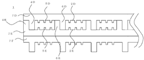
- FIG. 5 is a schematic view in which unit component members 7 having a configuration in which the tips of the spacing ribs 6 according to the first embodiment do not come into contact with each other at the time of stacking are stacked.
- the heat exchange element 1 shown in FIG. 5 (focusing only on the three layers) is configured by stacking unit constituent members 7 having the same structure (in order from the top, the upper stage is 7D, the interruption is 7E, and the lower stage is 7F). ing.
- the shielding rib 4D of the upper unit component member 7D and the shielding rib 4E of the middle unit component member 7E are in contact with each other on the side surface.
- the top surface portion of the shielding rib 4D of the upper unit component member 7D is in contact with the partition member 2E of the middle unit component member 7E, and the top surface of the shielding rib 4E of the middle unit component member 7E is the upper unit component member 7D. This is in contact with the partition member 2D.
- the spacing rib 6D of the upper unit component member 7D and the spacing rib 6E of the middle unit component member 7E are in contact with each other on the side surface.
- the top surface portion of the spacing rib 6D of the upper unit component member 7D is in contact with the partition member 2E of the middle unit component member 7E, and the top surface of the spacing rib 6E of the middle unit component member 7E is the upper unit component member 7D.
- a space surrounded by the shielding ribs 4D and 4E, the spacing ribs 6D and 6E, and the spacing ribs 6D and 6E is a ventilation path.
- Deflection suppression ribs 5D and 5E are provided in the ventilation path in order to prevent the cutting members 2D and 2E from bending.
- the deflection suppressing rib 5D of the upper unit component member 7D exists right above the deflection suppression rib 5E of the middle unit component member 7E, but it may not be directly above but may be shifted.
- the shielding ribs 4D and 4E also function as spacing ribs 6D and 6E that maintain the spacing between the partition members 2D and 2E in the stacking direction when stacked.
- the unit constituting member 7 is not provided with the shielding ribs 4D and 4E, but is provided with the spacing ribs 6D and 6E and the deflection suppressing ribs 5D and 5E, and the spacing ribs 6D and 6E at both ends are kept air shielded by a sealing material or the like. It may be.
- the spacing rib 6 ⁇ / b> D and the spacing rib 6 ⁇ / b> E are in contact with each other on the side surface.
- the partition members 2D and 2E Since the rib widths of the deflection suppressing ribs 5D and 5E are as narrow as possible, the partition members 2D and 2E have little influence on the heat transfer area and moisture permeable area for each layer, resulting in humidity exchange efficiency and total heat exchange efficiency. Can be improved. Furthermore, since the deflection suppressing ribs 5D and 5E can also play the role of fins, the fin effect also has the effect of improving the temperature exchange efficiency as a result. By making the deflection suppressing ribs 5D and 5E perpendicular to each other on the front and back sides of the partitioning members 2D and 2E, the respective expansion amounts of the partitioning members 2D and 2E surrounded by the deflection suppressing rib 5 in the width direction and the length direction of the paper.
- the heat exchange element 1 can be formed by integral molding by using a material that is difficult to join and that cannot be used with large deflection as the partition members 2D and 2E.
- FIG. 6 is a schematic diagram in which unit component members 7 having a configuration in which the tips of the spacing ribs 6 according to the first embodiment of the present invention are partly in contact with each other when stacked are stacked.
- the heat exchange element 1 shown in FIG. 6 (focusing on only three layers) is configured by laminating unit constituent members 7 having the same structure (in order from the top, the upper stage is 7G, the interruption is 7H, and the lower stage is 7I). ing.
- the shielding rib 4G of the upper unit component member 7G and the shielding rib 4H of the middle unit component member 7H are in contact with each other on the side surface.
- the top surface portion of the shielding rib 4G of the upper unit component member 7G contacts the partition member 2H of the middle unit component member 7H
- the top surface of the shielding rib 4H of the middle unit component member 7H is the upper unit component member 7G. Is in contact with the partition member 2G.
- the spacing rib 6D of the upper unit component member 7D and the spacing rib 6E of the middle unit component member 7E are in contact with each other at the side surface
- the top surface portion of the spacing rib 6D of the upper unit component member 7D is the middle unit component member.
- the top surface of the spacing rib 6E of the middle unit component member 7E is in contact with the partition member 2D of the upper unit component member 7D, but in FIG.
- all the spacing ribs 6G, 6H does not have this structure, and some of the spacing ribs 6G and 6H are in contact with each other at their tips.
- a space surrounded by the shielding ribs 4G and 4H, the spacing ribs 6G and 6H, and the spacing ribs 6G and 6H is a ventilation path.
- Deflection suppression ribs 5G and 5H are provided in the ventilation path in order to prevent the partition members 2G and 2H from bending.
- the deflection suppressing rib 5G of the upper unit component member 7G exists right above the deflection suppression rib 5H of the middle unit component member 7H, but may not be directly above but may be shifted.
- the shielding ribs 4G and 4H also function as spacing ribs 6G and 6H that hold the spacing between the partition members 2G and 2H in the stacking direction when stacked.
- the unit constituting member 7 is not provided with the shielding ribs 4G and 4H, but is provided with the spacing ribs 6G and 6H and the deflection suppressing ribs 5G and 5H, and the spacing ribs 6G and 6H at both ends are kept air shielded by a sealing material or the like. It may be.
- the spacing rib 6G and the spacing rib 6H are in contact with each other on the side surface, but need not be contacted on the side surface.
- the rib width of the deflection suppressing ribs 5G and 5H is as narrow as possible, there is little influence on the heat transfer area and the moisture permeable area for each partition member 2G and 2H1 layer. As a result, the humidity exchange efficiency and the total heat exchange efficiency are improved. Can be improved. Moreover, since the deflection suppressing ribs 5G and 5H can also play the role of fins, the fin effect also has the effect of improving the temperature exchange efficiency as a result.
- the deflection suppressing ribs 5G and 5H orthogonal to each other on the front and back of the partitioning members 2G and 2H, the width direction and the lengthwise direction of the paper of the partitioning members 2G and 2H surrounded by the deflection suppressing ribs 5G and 5H, respectively. Since the amount of elongation is reduced and the deflection rate in the region of the partition members 2G and 2H constrained by the deflection suppressing ribs 5G and 5H is reduced, pressure loss due to deterioration of the ventilation resistance is suppressed.
- the spacing ribs 6G and 6H are in contact with each other at the tips of the spacing ribs 6G and 6H, it is possible to secure the area of the air path as compared with the case where all of the spacing ribs 6G and 6H are in contact with each other. It is possible to suppress pressure loss due to deterioration. Further, since the amount of expansion / contraction is large so far, there is an effect that the heat exchange element 1 can be formed by integral molding by using a material that has been difficult to be joined in the past and that cannot be used with a large amount of deflection as the partition members 2D and 2E.
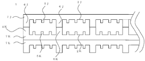
- FIG. 7 is a schematic diagram in which unit constituent members having a configuration in which the tips of the spacing ribs 6 according to the first embodiment of the present invention are all in contact with each other at the time of stacking.
- the heat exchange element 1 shown in FIG. 7 (focusing on only three layers) is configured by laminating unit constituent members 7 having the same structure (in order from the top, the upper stage is 7J, the interruption is 7K, and the lower stage is 7L). ing.
- the shielding rib 4J of the upper unit component member 7J and the shielding rib 4K of the middle unit component member 7K are in contact with each other at the top surface, and the spacing rib 6J of the upper unit component member 7J and the spacing rib 6K of the middle unit component member 7K.
- a space surrounded by the shielding ribs 4J and 4K, the spacing ribs 6J and 6K, and the spacing ribs 6J and 6K is a ventilation path.
- Deflection suppression ribs 5J and 5K are provided in the ventilation path in order to prevent the partition members 2J and 2K from bending.
- the deflection suppressing rib 5J of the upper unit component member 7J is present directly above the deflection suppressing rib 5K of the middle unit component member 7K, but may not be directly above but may be shifted.
- the shielding ribs 4J and 4K also function as spacing ribs 6G and 6H that hold the spacing between the partition members 2J and 2K in the stacking direction when stacked.
- the unit constituting member 7 is not provided with the shielding ribs 4J and 4K, but is provided with the spacing ribs 6G and 6H and the deflection suppressing ribs 5J and 5K, and the spacing ribs 6G and 6H at both ends are sealed with a sealing material or the like. It may be.
- the rib width of the deflection suppressing ribs 5J and 5K is as narrow as possible, there is little influence on the heat transfer area and moisture permeable area for each partition member 2J and 2K1 layer, and as a result, humidity exchange efficiency and total heat exchange efficiency are improved. Can be improved. Further, since the deflection suppressing ribs 5J and 5K can also play a role of fins, the fin effect also has an effect of improving the temperature exchange efficiency as a result.
- each of the paper in the width direction and the length direction of the partitioning members 2J and 2K surrounded by the deflection suppressing ribs 5J and 5K Since the amount of elongation is reduced and the deflection rate in the region of the partition members 2J and 2K constrained by the deflection suppression ribs 5J and 5K is also reduced, pressure loss due to deterioration of the ventilation resistance is suppressed.
- the spacing ribs 6J and 6K are in contact with each other at the tips of the spacing ribs 6J and 6K, it is possible to secure an area of the air path rather than in contact with each other on the side surface. Pressure loss due to deterioration can be suppressed. Furthermore, since the shielding ribs 4J and 4K are in contact with each other at their tips, the length of one side constituting the air passage is doubled, and the area of the air passage can be secured greatly. Pressure loss due to resistance deterioration can be suppressed.
- the heat exchange element 1 can be formed by integral molding by using as the partition members 2J and 2K a material that has been difficult to join and can not be used with a large amount of deflection.
- FIG. 8A is an explanatory diagram of an arrangement interval of the deflection suppressing ribs of the heat exchange element according to the first embodiment of the present invention.
- FIG. 8A shows one ventilation path surrounded by the spacing rib 6 or the shielding rib 4.
- the height of the air path is g [mm]
- the arrangement interval of the deflection suppressing ribs is p [mm]
- the dimensional change rate during expansion of the partition member is ⁇ .
- the dimensional change rate ⁇ is obtained by dividing the length of expansion of the partition member by the reference of the partition member before expansion.
- the dimension of the expansion part of the partition member is defined as the dimension of the expanded part when the partition member is fully expanded after leaving the partition member for a sufficient time in an environmental condition where the relative humidity is almost as close as 100% RH.
- the conditions under which the ventilation path is completely blocked by the partition member will be described. Since it can be considered that the temperature and humidity of the air flowing in one ventilation path are substantially the same, it is considered that the elongation at the facing position of the partition member 2 constituting the upper surface and the lower surface of the ventilation path is the same. I can do it. Therefore, if the partition member 2 constituting the upper surface and the lower surface closes the ventilation path by half, the entire ventilation path is blocked. Thus, the conditions which the partition member 2 of an upper surface or a lower surface obstruct
- the interval holding member 3 including the shielding rib 4, the deflection suppressing rib 5, and the interval rib 6 is generally square (when the primary and secondary air currents are orthogonal) or a parallelogram (also the air currents are obliquely crossed).
- the shielding rib 4 needs to be designed to have a wider rib width than the spacing rib 6 in order to increase the reliability of the partition member 2 against air leakage.
- the rib width be as narrow as possible. The amount of resin used is also reduced due to the narrow rib width.
- the resin used for the spacing member 3 is polypropylene (PP), acrylonitrile-butadiene-styrene (ABS), polystyrene (PS), acrylonitrile-styrene (AS), polycarbonate (PC), and other general resins in a desired shape. Any material that can be molded may be used. Since the ribs are formed of resin in this way, deformation of the spacing member 3 due to a change in humidity such as the corrugated shape of FIG. 1 in which paper is used as the spacing member 3 can be suppressed. Can be achieved. In addition, these resins are made flame retardant by adding a flame retardant, and inorganic components are added to improve dimensional stability and strength.
Landscapes
- Engineering & Computer Science (AREA)
- Physics & Mathematics (AREA)
- Thermal Sciences (AREA)
- Mechanical Engineering (AREA)
- General Engineering & Computer Science (AREA)
- Heat-Exchange Devices With Radiators And Conduit Assemblies (AREA)
Abstract
Description
そのため、特許文献2のような仕切部材と間隔保持部材を樹脂で一体成形する場合では、間隔保持部材の配置間隔を狭くすることで、間隔保持部材で仕切部材のたわみによる風路閉塞を緩和でき、さらに通風路の断面形状の崩れによる通風抵抗の増加を妨げることができるが、風路の有効面積が小さくなってしまうため通風抵抗が増加してしまう。さらに間隔保持部材の配置間隔を狭くしてしまうと積層時に間隔保持部材が上下層の仕切部材に接触する部分が増加してしまうため、伝熱面積、透湿面積の減少により全熱交換効率が減少してしまうという課題があった。
本発明は上述した従来の課題を解決するためになされたものであり、全熱交換効率向上のための緻密かつ高密度な素材を仕切部材に使用しても、温湿度変化による仕切部材のたわみを抑制することで通風抵抗の悪化低減を図れ、かつ間隔保持部材の増加による伝熱面積減少を抑制することで全熱交換効率の向上を図ることができる熱交換素子を得ることを目的としている。
以下、本発明の実施の形態1について図面を参照して説明する。図1は本発明の実施の形態1にかかる熱交換素子の斜視図であり、図2は本発明の実施の形態1にかかる単位構成部材の1層分の斜視図であり、図3は本発明の実施の形態1にかかる単位構成部材1層分である図2のC部拡大図である。
図1及び図2に示すように、本発明の実施の形態1における熱交換素子1は、上下を通過する空気の熱交換を行う伝熱性と透湿性と遮蔽性を有する仕切部材2と、この仕切部材2を所定間隔に保持する間隔保持部材3とを一体成形して形成した単位構成部材7を一枚ごとに90度反転させて交互に積層したものであり、仕切部材2の片側を通過する一次気流Aと仕切部材2の他側を通過する二次気流Bとが仕切部材2を介して、熱と湿度を交換させるものである。
以下で熱交換素子1を構成する各要素について詳細を説明する。
図4に示すように間隔保持部材3は、仕切部材2の膨張によるたわみを抑制するものであり、熱交換素子1の仕切部材2以外の部分を構成している。具体的には、間隔保持部材3は、熱交換素子1の外枠を構成し、熱交換素子1両端からの空気漏れを防止するため、気流が流れる方向に並行し、両端に設けられた遮蔽リブ4と、遮蔽リブ4と並行して所定間隔で複数本設けられ熱交換素子1を積層した際に積層方向の仕切部材2の間隔を保持し通風路を形成する間隔リブ6と、隣り合う間隔リブ6間に間隔リブ6と並行に所定間隔に複数本設けられ仕切部材2のたわみによる風路閉塞を抑制するたわみ抑制リブ5によって構成されている。たわみ抑制リブ5は間隔保持リブ6よりも高さが低く幅も細く形成されており、これらの遮蔽リブ4、たわみ抑制リブ5、間隔リブ6は仕切部材2の表と裏の両面に表と裏で90度ずらして形成されている。なお、たわみ抑制リブ5は極力通風の圧力損失を抑え、仕切部材2の伝熱面積や透湿面積を阻害しないように細く薄い形状にすることが望ましい。従ってたわみ抑制リブ5のリブ高さは低く、リブ幅は薄いことが望まれる。具体的には積層時に上下層のたわみ抑制リブ5と干渉(接触)しない様に、たわみ抑制リブ5のリブ高さは間隔リブ6のリブ高さの1/2未満が望ましい。また、たわみ抑制リブ5のリブ幅は伝熱面積、透湿面積の阻害要因となるため、成形にて可能な限り極力細いことが望まれる。
以下この熱交換素子1を90度ずつずらして積層する具体的な構成について図5乃至7を参照して説明する。
図5に示す熱交換素子1(三層のみ着目)は、同一構造を有する単位構成部材7を積層(上から順番に上段は7D、中断は7E、下段は7Fとする)することにより構成されている。上段の単位構成部材7Dの遮蔽リブ4Dと中段の単位構成部材7Eの遮蔽リブ4Eは側面で当接している。さらに、上段の単位構成部材7Dの遮蔽リブ4Dの天面部は中段の単位構成部材7Eの仕切部材2Eと当接し、中段の単位構成部材7Eの遮蔽リブ4Eの天面は上段の単位構成部材7Dの仕切部材2Dと当接している。また同様に、上段の単位構成部材7Dの間隔リブ6Dと中段の単位構成部材7Eの間隔リブ6Eは側面で当接している。さらに、上段の単位構成部材7Dの間隔リブ6Dの天面部は中段の単位構成部材7Eの仕切部材2Eと当接し、中段の単位構成部材7Eの間隔リブ6Eの天面は上段の単位構成部材7Dの仕切部材2Dと当接している。この遮蔽リブ4D,4Eと間隔リブ6D,6E、及び間隔リブ6D,6E同士で囲まれた空間が通風路となる。この通風路内に、切部材2D,2Eがたわむのを抑制するために、たわみ抑制リブ5D,5Eが設けられている。図5では、上段の単位構成部材7Dのたわみ抑制リブ5Dは中段の単位構成部材7Eのたわみ抑制リブ5Eの真上に存在するが、真上でなく、ずれていてもよい。なお、遮蔽リブ4D,4Eは積層した際に積層方向の仕切部材2D,2Eの間隔を保持する間隔リブ6D,6Eとしての機能も有している。また、単位構成部材7は遮蔽リブ4D,4Eを設けず、間隔リブ6D,6Eとたわみ抑制リブ5D,5Eを設け、両端の間隔リブ6D,6Eをシール材等で空気の遮蔽性を保つ構造であってもよい。図5において間隔リブ6D及び間隔リブ6Eは側面で当接しているが、側面で当接していなくてももちろんよい。
たわみ抑制リブ5D,5Eを仕切部材2D,2Eの表裏で直交する構成にすることで、たわみ抑制リブ5で囲われた仕切部材2D,2Eの紙の幅方向と長さ方向のそれぞれの伸び量を少なくさせ、かつ、たわみ抑制リブ5D,5Eで拘束された仕切部材2D,2Eの領域内におけるたわみ率も軽減させてくれるため、通風抵抗の悪化による圧力損失を抑制してくれる。また、従来は伸び縮み量の大きいため、接合が難しく、たわみが大きく使えなかった素材も仕切部材2D,2Eとして用いて一体成形で熱交換素子1を形成できる効果もある。
図6に示す熱交換素子1(三層のみ着目)は、同一構造を有する単位構成部材7を積層(上から順番に上段は7G、中断は7H、下段は7Iとする)することにより構成されている。上段の単位構成部材7Gの遮蔽リブ4Gと中段の単位構成部材7Hの遮蔽リブ4Hは側面で当接している。さらに、上段の単位構成部材7Gの遮蔽リブ4Gの天面部は中段の単位構成部材7Hの仕切部材2Hと当接し、中段の単位構成部材7Hの遮蔽リブ4Hの天面は上段の単位構成部材7Gの仕切部材2Gと当接している。図5では、上段の単位構成部材7Dの間隔リブ6Dと中段の単位構成部材7Eの間隔リブ6Eは側面で当接し、上段の単位構成部材7Dの間隔リブ6Dの天面部は中段の単位構成部材7Eの仕切部材2Eと当接し、中段の単位構成部材7Eの間隔リブ6Eの天面は上段の単位構成部材7Dの仕切部材2Dと当接しているが、図6では、全ての間隔リブ6G,6Hがこの構造になっておらず、一部の間隔リブ6G,6Hはそれぞれの先端同士で当接している。遮蔽リブ4G,4Hと間隔リブ6G,6H、及び間隔リブ6G,6H同士で囲まれた空間が通風路となる。この通風路内に、仕切部材2G,2Hがたわむのを抑制するために、たわみ抑制リブ5G,5Hが設けられている。なお、図6では、上段の単位構成部材7Gのたわみ抑制リブ5Gは中段の単位構成部材7Hのたわみ抑制リブ5Hの真上に存在するが、真上でなく、ずれていてもよい。なお、遮蔽リブ4G,4Hは積層した際に積層方向の仕切部材2G,2Hの間隔を保持する間隔リブ6G,6Hとしての機能も有している。また、単位構成部材7は遮蔽リブ4G,4Hを設けず、間隔リブ6G,6Hとたわみ抑制リブ5G,5Hを設け、両端の間隔リブ6G,6Hをシール材等で空気の遮蔽性を保つ構造であってもよい。図6において間隔リブ6G及び間隔リブ6Hは側面で当接しているが、側面で当接していなくてももちろんよい。
たわみ抑制リブ5G,5Hを仕切部材2G,2Hの表裏で直交する構成にすることで、たわみ抑制リブ5G,5Hで囲われた仕切部材2G,2Hの紙の幅方向と長さ方向のそれぞれの伸び量を少なくさせ、かつ、たわみ抑制リブ5G,5Hで拘束された仕切部材2G,2Hの領域内におけるたわみ率も軽減させてくれるため、通風抵抗の悪化による圧力損失を抑制してくれる。さらに、間隔リブ6G,6Hの一部が間隔リブ6G,6Hの先端同士で互いに当接しているため、全て側面で当接するよりも風路の面積を確保することが可能となるため、通風抵抗の悪化による圧力損失を抑制できる。また、今まで伸び縮み量の大きいため、従来は接合が難しく、たわみが大きく使えなかった素材も仕切部材2D,2Eとして用いて一体成形で熱交換素子1を形成できる効果もある。
図7に示す熱交換素子1(三層のみ着目)は、同一構造を有する単位構成部材7を積層(上から順番に上段は7J、中断は7K、下段は7Lとする)することにより構成されている。
上段の単位構成部材7Jの遮蔽リブ4Jと中段の単位構成部材7Kの遮蔽リブ4Kは天面部で互いに当接し、上段の単位構成部材7Jの間隔リブ6Jと中段の単位構成部材7Kの間隔リブ6Kは天面部で互いに当接している。この遮蔽リブ4J,4Kと間隔リブ6J,6K、及び間隔リブ6J,6K同士で囲まれた空間が通風路となる。この通風路内に、仕切部材2J,2Kがたわむのを抑制するために、たわみ抑制リブ5J,5Kが設けられている。図7では、上段の単位構成部材7Jのたわみ抑制リブ5Jは中段の単位構成部材7Kのたわみ抑制リブ5Kの真上に存在するが、真上でなく、ずれていてもよい。なお、遮蔽リブ4J,4Kは積層した際に積層方向の仕切部材2J,2Kの間隔を保持する間隔リブ6G,6Hとしての機能も有している。また、単位構成部材7は遮蔽リブ4J,4Kを設けず、間隔リブ6G,6Hとたわみ抑制リブ5J,5Kを設け、両端の間隔リブ6G,6Hをシール材等で空気の遮蔽性を保つ構造であってもよい。
たわみ抑制リブ5J,5Kを仕切部材2J,2Kの表裏で直交する構成にすることで、たわみ抑制リブ5J,5Kで囲われた仕切部材2J,2Kの紙の幅方向と長さ方向のそれぞれの伸び量を少なくさせ、かつ、たわみ抑制リブ5J,5Kで拘束された仕切部材2J,2Kの領域内におけるたわみ率も軽減させてくれるため、通風抵抗の悪化による圧力損失を抑制してくれる。さらに、間隔リブ6J,6Kの全てが間隔リブ6J,6Kの先端同士で互いに当接しているため、側面で互いに当接するよりも風路の面積を確保することが可能となるため、通風抵抗の悪化による圧力損失を抑制できる。さらに、遮蔽リブ4J,4Kは先端同士で互いに当接しているため、風路を構成する一辺の長さが2倍になり、風路の面積を大幅に確保することが可能となるため、通風抵抗の悪化による圧力損失を抑制できる。また、今まで伸び縮み量の大きいため、従来は接合が難しく、たわみが大きく使えなかった素材も仕切部材2J,2Kとして用いて一体成形で熱交換素子1を形成できる効果もある。
図8は、本発明の実施の形態1にかかる熱交換素子のたわみ抑制リブの配置間隔についての説明図である。
図8(a)は、間隔リブ6または遮蔽リブ4で囲まれた1つの通風路を示している。風路の高さをg[mm]、たわみ抑制リブの配置間隔をp[mm]、仕切部材の膨張時の寸法変化率をσとする。寸法変化率σとは、仕切部材の膨張分の長さを膨張する前の仕切部材の基準で割ったものである。なお、仕切部材の膨張分の寸法とは、相対湿度が100%RHに限りなく近い環境条件に仕切部材を充分な時間放置した後の膨張しきった際の膨張した分の寸法と定義する。
一つの通風路内を流れる空気の温度及び湿度は略同じであると考えることが出来るため、通風路の上面と下面を構成する仕切部材2の対面する位置での伸びは同じであると考えることが出来る。そのため、上面及び下面を構成する仕切部材2が通風路を半分ずつ閉塞してしまうと一つの通風路全体を閉塞してしまう。このように上面又は下面の仕切部材2が通風路の半分を閉塞してしまう条件を以下に示す。
一つの通風路の上面又は下面の仕切部材2が十分膨張した後の仕切部材の長さはp(1+σ)である。また仕切部材2により風路の半分を閉塞するのに必要な長さはp+2(g/2)である。このため、
(数1) p(1+σ)=p+2(g/2)
すなわち、
(数2) p=g/σ
の関係を満たすときに仕切部材2が通風路を完全に塞いでしまう。よって、仕切部材2が通風路を完全に塞がないためには、
(数3) p<g/σ
の関係を満たす必要がある。
上記(数3)の要件を満たすようにたわみ抑制リブ5を配置することで、仕切部材が通風路を完全に閉塞してしまうという事態を回避することが出来る。
通風路の上下面を構成する仕切部材2が完全に通風路を閉塞しなくても、仕切部材2同士が接着してしまうと、表面に施されたコーティングが剥がれるといった問題や、環境が変化し、仕切部材2がもとの長さに戻ろうとするときの回復速度が遅くなってしまうという問題が生じる。このため、好ましくは、通風路の上下面を構成する仕切部材2が互いに接着しないようにたわみ抑制リブ5を配置することが望ましい。
仕切部材が一番たわむのは、たわみ抑制リブ5から距離が一番離れた位置であるたわみ抑制リブ5間の中間地点であるため、この中間地点が風路の高さg[mm]の中間地点に達したときに仕切部材2同士の接触が開始する可能性がある。一つの通風路の上面又は下面の仕切部材が十分膨張した後の仕切部材2の長さはp(1+σ)である。このため、
(数4) g/2=

すなわち、
(数5) p=

の関係を満たすときに通風路の上下面を構成する仕切部材2が互いに接着し始める。よって仕切部材が互いに接着しないようにするためには、
(数6) p<

の関係を満たす必要がある。(数3)及び(数6)に示すように、たわみ抑制リブの配置間隔は通風路の高さgに比例して、寸法変化率σに反比例する。このため、通風路の高さが高い場合は配置間隔を広げることができ、寸法変化率が大きい仕切部材を用いた場合は配置間隔を狭くする必要がある。
2・2D・2E・2G・2H・2J・2K 仕切部材
3 間隔保持部材
4・4D・4E・4G・4H・4J・4K 遮蔽リブ
5・5D・5E・5G・5H・5J・5K たわみ抑制リブ
6・6D・6E・6G・6H・6J・6K 間隔リブ
7・7D・7E・7F・7G・7H・7I・7J・7K・7L 単位構成部材
A 一次気流
B 二次気流
p たわみ抑制リブの配置間隔
g 風路高さ
Claims (16)
- 伝熱性と透湿性を有する仕切部材と、
前記仕切部材を所定間隔に保持する間隔保持部材と、
で形成された単位構成部材を積層し、前記仕切部材の表面側を通過する一次気流と前記仕切部材の裏面側を前記一次気流と交差して通過する二次気流とが前記仕切部材を介して熱と湿度を交換する熱交換素子において、
前記間隔保持部材は、
前記仕切部材の表面に前記一次気流が流れる方向と並行に所定間隔ごとに設けられた第一間隔リブと、
前記仕切部材の裏面に前記二次気流が流れる方向と並行に所定間隔ごとに設けられた第二間隔リブと、
前記第二間隔リブと接続され、前記第一間隔リブの間を所定間隔ごとに並行して設けられた前記第一間隔リブよりも高さが低い第一たわみ抑制リブと、
前記第一間隔リブと接続され、前記第二間隔リブの間を所定間隔ごとに並行して設けられた前記第二間隔リブよりも高さが低い第二たわみ抑制リブと、
を備えたことを特徴とする熱交換素子。
- 伝熱性と透湿性を有する仕切部材と、
前記仕切部材を所定間隔に保持する間隔保持部材と、
で形成された単位構成部材を積層し、前記仕切部材の表面側を通過する一次気流と前記仕切部材の裏面側を前記一次気流と交差して通過する二次気流とが前記仕切部材を介して熱と湿度を交換する熱交換素子において、
前記間隔保持部材は、
前記仕切部材の表面の両側にそれぞれ前記一次気流が流れる方向と並行に設けられた第一遮蔽リブと、
前記仕切部材の裏面の両側にそれぞれ前記二次気流が流れる方向と並行に設けられた第二遮蔽リブと、
前記第二遮蔽リブと接続され、前記第一遮蔽リブの間を所定間隔ごとに並行して設けられた第一間隔リブと、
前記第一遮蔽リブと接続され、前記第二遮蔽リブの間を所定間隔ごとに並行して設けられた第二間隔リブと、
前記第二遮蔽リブと接続され、前記第一間隔リブの間を所定間隔ごとに並行して設けられた前記第一間隔リブよりも高さが低い第一たわみ抑制リブと、
前記第一遮蔽リブと接続され、前記第二間隔リブの間を所定間隔ごとに並行して設けられた前記第二間隔リブよりも高さが低い第二たわみ抑制リブと、
を備えたことを特徴とする熱交換素子。
- 前記第一及び第二たわみ抑制リブの幅が、前記第一及び第二間隔リブの幅より狭いことを特徴とする請求項1乃至2のいずれかに記載の熱交換素子。
- 前記単位構成部材は矩形形状であり、前記第一及び第二間隔リブおよび前記第一及び第二たわみ抑制リブは、前記単位構成部材の一辺からその対向する他方の辺まで連続した線状に形成されていることを特徴とする請求項1乃至3のいずれか記載の熱交換素子。
- 前記単位構成部材は正方形で、前記仕切部材の両面に前記間隔リブおよび前記たわみ抑制リブが設けられ、前記仕切部材の表面と前記仕切部材の裏面で前記第一及び第二間隔リブのピッチが同一であるとともに90度ずれて設けられていることを特徴とする請求項1乃至4のいずれかに記載の熱交換素子。
- 前記単位構成部材を一枚ごとに90度反転させて交互に積層することを特徴とする請求項1乃至5のいずれかに記載の熱交換素子。
- 前記単位構成部材の仕切部材及び前記間隔保持部材は一体成形されることを特徴とする請求項1乃至6のいずれかに記載の熱交換素子。
- 前記間隔保持部材は、樹脂で形成されることを特徴とする請求項1乃至6のいずれかに記載の熱交換素子。
- 前記単位構成部材が積層された熱交換素子において、
一方の前記単位構成部材に形成された前記第一及び第二間隔リブの先端と、積層されている他方の前記単位構成部材に形成された前記仕切部材が当接していることを特徴とする請求項1乃至8のいずれかに記載の熱交換素子。
- 前記単位構成部材が積層された熱交換素子において、
一方の前記単位構成部材に形成された前記第一及び第二間隔リブの先端と、積層されている他方の前記単位構成部材に形成された前記第一及び第二間隔リブの先端が接触していることを特徴とする請求項1乃至8のいずれかに記載の熱交換素子。
- 前記単位構成部材が積層された熱交換素子において、
一方の前記単位構成部材に形成された前記第一及び第二間隔リブの一部の先端と、積層されている他方の前記単位構成部材に形成された前記仕切部材が当接し、
他方の前記単位構成部材に形成された前記第一及び第二間隔リブの一部の先端と、積層されている一方の前記単位構成部材に形成された前記仕切部材が当接していることを特徴とする請求項1乃至8のいずれかに記載の熱交換素子。
- 前記第一及び第二たわみ抑制リブの高さは前記第一及び第二間隔リブの高さの1/2未満であることを特徴とする請求項1乃至請求項11のいずれかに記載の熱交換素子。
- 前記仕切部材の透気抵抗度が5000秒以上であることを特徴とする請求項1乃至請求項12のいずれかに記載の熱交換素子。
- 前記単位構成部材を積層することにより形成される通風路の高さをg、
前記仕切部材が膨張したときの膨張した分の長さを膨張する前の基準寸法で割った寸法変化率をσ、
前記たわみ抑制リブの配置間隔をpとしたときに、
前記pは、p<g/σの関係を満たすことを特徴とする請求項1乃至13のいずれかに記載の熱交換素子。
- 前記単位構成部材を積層することにより形成される通風路の高さをg、
前記仕切部材が膨張したときの膨張した分の長さを膨張する前の基準寸法で割った寸法変化率をσ、
前記たわみ抑制リブの配置間隔をpとしたときに、
前記pは、p<
の関係を満たすことを特徴とする請求項1乃至13のいずれかに記載の熱交換素子。
- 前記一次気流と前記二次気流が交差する箇所に熱交換素子を備えた空気調和装置において、前記熱交換素子は請求項1乃至請求項15のいずれかに記載の熱交換素子であることを特徴とする空気調和装置。
Priority Applications (7)
| Application Number | Priority Date | Filing Date | Title |
|---|---|---|---|
| EP12874435.6A EP2851642B1 (en) | 2012-04-18 | 2012-06-13 | Heat-exchange element and air conditioner |
| US14/385,286 US9903669B2 (en) | 2012-04-18 | 2012-06-13 | Heat exchange element and air conditioner |
| KR1020147028751A KR20140137433A (ko) | 2012-04-18 | 2012-06-13 | 열교환 소자 및 공기조화 장치 |
| PL12874435T PL2851642T3 (pl) | 2012-04-18 | 2012-06-13 | Element wymiany ciepła i klimatyzator |
| JP2014510972A JP5781221B2 (ja) | 2012-04-18 | 2012-06-13 | 熱交換素子及び空気調和装置 |
| CN201280072417.8A CN104246411B (zh) | 2012-04-18 | 2012-06-13 | 热交换元件及空气调节装置 |
| TW101126561A TWI525294B (zh) | 2012-04-18 | 2012-07-24 | Heat exchange components and air conditioning devices |
Applications Claiming Priority (2)
| Application Number | Priority Date | Filing Date | Title |
|---|---|---|---|
| JPPCT/JP2012/002681 | 2012-04-18 | ||
| PCT/JP2012/002681 WO2013157040A1 (ja) | 2012-04-18 | 2012-04-18 | 熱交換素子及び空気調和装置 |
Publications (1)
| Publication Number | Publication Date |
|---|---|
| WO2013157055A1 true WO2013157055A1 (ja) | 2013-10-24 |
Family
ID=49383037
Family Applications (2)
| Application Number | Title | Priority Date | Filing Date |
|---|---|---|---|
| PCT/JP2012/002681 WO2013157040A1 (ja) | 2012-04-18 | 2012-04-18 | 熱交換素子及び空気調和装置 |
| PCT/JP2012/003840 WO2013157055A1 (ja) | 2012-04-18 | 2012-06-13 | 熱交換素子及び空気調和装置 |
Family Applications Before (1)
| Application Number | Title | Priority Date | Filing Date |
|---|---|---|---|
| PCT/JP2012/002681 WO2013157040A1 (ja) | 2012-04-18 | 2012-04-18 | 熱交換素子及び空気調和装置 |
Country Status (7)
| Country | Link |
|---|---|
| US (1) | US9903669B2 (ja) |
| EP (1) | EP2851642B1 (ja) |
| KR (1) | KR20140137433A (ja) |
| CN (1) | CN104246411B (ja) |
| PL (1) | PL2851642T3 (ja) |
| TW (1) | TWI525294B (ja) |
| WO (2) | WO2013157040A1 (ja) |
Cited By (2)
| Publication number | Priority date | Publication date | Assignee | Title |
|---|---|---|---|---|
| US9664457B2 (en) | 2011-10-26 | 2017-05-30 | Mitsubishi Electric Corporation | Total heat exchange element and manufacturing method thereof |
| JP2020051655A (ja) * | 2018-09-26 | 2020-04-02 | パナソニックIpマネジメント株式会社 | 熱交換素子及びそれを用いた熱交換形換気装置 |
Families Citing this family (19)
| Publication number | Priority date | Publication date | Assignee | Title |
|---|---|---|---|---|
| WO2013157045A1 (ja) | 2012-04-20 | 2013-10-24 | 三菱電機株式会社 | 熱交換素子 |
| CN107208985B (zh) * | 2014-12-18 | 2019-07-26 | 迈科电气设备厂有限公司 | 换热器和具有换热器的空气技术设备 |
| FR3036179A1 (fr) * | 2015-05-12 | 2016-11-18 | Tmw | Echangeur thermique moule en deux parties et procede de fabrication d’un tel echangeur |
| JP2017090026A (ja) * | 2015-11-17 | 2017-05-25 | 株式会社東芝 | 熱交換器及び換気装置 |
| KR102511542B1 (ko) * | 2015-12-02 | 2023-03-20 | 삼성디스플레이 주식회사 | 회로 기판 및 이를 포함하는 표시장치 |
| CN106052464A (zh) * | 2016-06-17 | 2016-10-26 | 安徽天祥空调科技有限公司 | 一种平行流蒸发器积液器主片及其制备工艺 |
| KR102628091B1 (ko) * | 2016-09-28 | 2024-01-23 | 엘지전자 주식회사 | 디스플레이 장치 |
| GB2561894B (en) | 2017-04-28 | 2019-10-16 | Amscreen Group Ltd | Environment control in electronic displays |
| GB2565997B (en) | 2017-04-28 | 2019-10-16 | Amscreen Group Ltd | Crossflow heat-exchangers |
| GB2561895B (en) * | 2017-04-28 | 2019-10-16 | Amscreen Group Ltd | Cooling of electronic displays |
| GB2561893B (en) | 2017-04-28 | 2020-04-15 | Amscreen Group Ltd | Environment control in electronic apparatus |
| GB201706770D0 (en) | 2017-04-28 | 2017-06-14 | Amscreen Group Ltd | Control of electronic displays |
| CN107504833A (zh) * | 2017-09-20 | 2017-12-22 | 台州德备环境设备科技有限公司 | 热交换芯片及热交换芯 |
| US10113767B1 (en) | 2018-02-01 | 2018-10-30 | Berg Companies, Inc. | Air handling unit |
| CN108709257B (zh) * | 2018-06-15 | 2023-12-19 | 广东芬尼克兹节能设备有限公司 | 一种除湿机 |
| CN111412763B (zh) * | 2018-07-20 | 2021-07-23 | 山东大学 | 一种汽液两相流的换热管内部尺寸的设计方法 |
| US11306979B2 (en) * | 2018-12-05 | 2022-04-19 | Hamilton Sundstrand Corporation | Heat exchanger riblet and turbulator features for improved manufacturability and performance |
| AU2022230856A1 (en) * | 2021-03-03 | 2023-10-12 | Daikin Industries, Ltd. | Heat exchanger and air treatment device |
| US11686537B2 (en) * | 2021-04-06 | 2023-06-27 | General Electric Company | Heat exchangers and methods of manufacturing the same |
Citations (8)
| Publication number | Priority date | Publication date | Assignee | Title |
|---|---|---|---|---|
| JPH03279793A (ja) * | 1990-03-28 | 1991-12-10 | Matsushita Electric Ind Co Ltd | 全熱交換素子 |
| JPH08110076A (ja) * | 1994-10-11 | 1996-04-30 | Matsushita Seiko Co Ltd | 熱交換素子 |
| JPH08178577A (ja) * | 1994-12-26 | 1996-07-12 | Daikin Ind Ltd | 熱交換エレメント |
| JPH10506178A (ja) * | 1994-09-27 | 1998-06-16 | ハドワコ リミテッド オーワイ | 熱交換器 |
| JP2000502788A (ja) * | 1995-12-29 | 2000-03-07 | ランテック・プロダクツ・インコーポレーテッド | サーマルベッド及び触媒ベッド用のチャネルを有するセラミックパッキング |
| JP2003287387A (ja) | 2002-03-28 | 2003-10-10 | Matsushita Ecology Systems Co Ltd | 熱交換膜および熱交換素子 |
| JP2007285691A (ja) * | 2006-03-22 | 2007-11-01 | Matsushita Electric Ind Co Ltd | 熱交換器 |
| WO2008126372A1 (ja) * | 2007-03-30 | 2008-10-23 | Panasonic Corporation | 熱交換素子 |
Family Cites Families (21)
| Publication number | Priority date | Publication date | Assignee | Title |
|---|---|---|---|---|
| JPS4719990B1 (ja) | 1969-03-20 | 1972-06-07 | ||
| JPS5579996A (en) * | 1978-12-14 | 1980-06-16 | Teijin Ltd | Wet heat exchanger |
| AU624662B2 (en) * | 1988-12-12 | 1992-06-18 | Vulcan Australia Limited | Heat exchanger |
| JPH04313694A (ja) * | 1991-04-10 | 1992-11-05 | Matsushita Electric Ind Co Ltd | 熱交換素子 |
| JPH07208891A (ja) | 1994-01-14 | 1995-08-11 | Toshiba Corp | 熱交換素子 |
| JP2690272B2 (ja) | 1994-08-04 | 1997-12-10 | 松下精工株式会社 | 熱交換素子 |
| JPH08145588A (ja) | 1994-11-18 | 1996-06-07 | Matsushita Seiko Co Ltd | 熱交換素子 |
| JPH09152291A (ja) | 1995-11-29 | 1997-06-10 | Matsushita Seiko Co Ltd | 熱交換素子 |
| US6145588A (en) * | 1998-08-03 | 2000-11-14 | Xetex, Inc. | Air-to-air heat and moisture exchanger incorporating a composite material for separating moisture from air technical field |
| US6841601B2 (en) * | 2001-03-13 | 2005-01-11 | Dais-Analytic Corporation | Crosslinked polymer electrolyte membranes for heat and moisture exchange devices |
| JP4507995B2 (ja) * | 2005-06-14 | 2010-07-21 | パナソニック株式会社 | 熱交換機器 |
| US7320361B2 (en) * | 2005-10-28 | 2008-01-22 | Mitsubishi Denki Kabushiki Kaisha | Heat exchanger |
| JP4770534B2 (ja) | 2006-03-22 | 2011-09-14 | パナソニック株式会社 | 熱交換器 |
| US8002023B2 (en) * | 2006-03-22 | 2011-08-23 | Panasonic Corporation | Heat exchanger and its manufacturing method |
| JP4765706B2 (ja) * | 2006-03-22 | 2011-09-07 | パナソニック株式会社 | 熱交換器の製造方法 |
| JP4816517B2 (ja) | 2006-09-28 | 2011-11-16 | パナソニック株式会社 | 熱交換素子 |
| CN101233381B (zh) * | 2006-10-03 | 2010-06-09 | 三菱电机株式会社 | 总热交换元件及总热交换器 |
| DE102009038154B4 (de) | 2009-08-20 | 2014-01-09 | Continental Automotive Gmbh | Temperiereinheit und Batteriesystem umfassend eine solche Temperiereinheit |
| US9429366B2 (en) * | 2010-09-29 | 2016-08-30 | Kraton Polymers U.S. Llc | Energy recovery ventilation sulfonated block copolymer laminate membrane |
| US20140014289A1 (en) * | 2012-07-11 | 2014-01-16 | Kraton Polymers U.S. Llc | Enhanced-efficiency energy recovery ventilation core |
| US20140262125A1 (en) * | 2013-03-14 | 2014-09-18 | Venmar Ces, Inc. | Energy exchange assembly with microporous membrane |
-
2012
- 2012-04-18 WO PCT/JP2012/002681 patent/WO2013157040A1/ja active Application Filing
- 2012-06-13 PL PL12874435T patent/PL2851642T3/pl unknown
- 2012-06-13 WO PCT/JP2012/003840 patent/WO2013157055A1/ja active Application Filing
- 2012-06-13 CN CN201280072417.8A patent/CN104246411B/zh active Active
- 2012-06-13 KR KR1020147028751A patent/KR20140137433A/ko active Search and Examination
- 2012-06-13 US US14/385,286 patent/US9903669B2/en active Active
- 2012-06-13 EP EP12874435.6A patent/EP2851642B1/en active Active
- 2012-07-24 TW TW101126561A patent/TWI525294B/zh active
Patent Citations (8)
| Publication number | Priority date | Publication date | Assignee | Title |
|---|---|---|---|---|
| JPH03279793A (ja) * | 1990-03-28 | 1991-12-10 | Matsushita Electric Ind Co Ltd | 全熱交換素子 |
| JPH10506178A (ja) * | 1994-09-27 | 1998-06-16 | ハドワコ リミテッド オーワイ | 熱交換器 |
| JPH08110076A (ja) * | 1994-10-11 | 1996-04-30 | Matsushita Seiko Co Ltd | 熱交換素子 |
| JPH08178577A (ja) * | 1994-12-26 | 1996-07-12 | Daikin Ind Ltd | 熱交換エレメント |
| JP2000502788A (ja) * | 1995-12-29 | 2000-03-07 | ランテック・プロダクツ・インコーポレーテッド | サーマルベッド及び触媒ベッド用のチャネルを有するセラミックパッキング |
| JP2003287387A (ja) | 2002-03-28 | 2003-10-10 | Matsushita Ecology Systems Co Ltd | 熱交換膜および熱交換素子 |
| JP2007285691A (ja) * | 2006-03-22 | 2007-11-01 | Matsushita Electric Ind Co Ltd | 熱交換器 |
| WO2008126372A1 (ja) * | 2007-03-30 | 2008-10-23 | Panasonic Corporation | 熱交換素子 |
Cited By (2)
| Publication number | Priority date | Publication date | Assignee | Title |
|---|---|---|---|---|
| US9664457B2 (en) | 2011-10-26 | 2017-05-30 | Mitsubishi Electric Corporation | Total heat exchange element and manufacturing method thereof |
| JP2020051655A (ja) * | 2018-09-26 | 2020-04-02 | パナソニックIpマネジメント株式会社 | 熱交換素子及びそれを用いた熱交換形換気装置 |
Also Published As
| Publication number | Publication date |
|---|---|
| CN104246411A (zh) | 2014-12-24 |
| EP2851642B1 (en) | 2018-09-12 |
| EP2851642A4 (en) | 2016-03-02 |
| CN104246411B (zh) | 2017-04-05 |
| US20150075758A1 (en) | 2015-03-19 |
| TWI525294B (zh) | 2016-03-11 |
| TW201344118A (zh) | 2013-11-01 |
| US9903669B2 (en) | 2018-02-27 |
| EP2851642A1 (en) | 2015-03-25 |
| KR20140137433A (ko) | 2014-12-02 |
| WO2013157040A1 (ja) | 2013-10-24 |
| PL2851642T3 (pl) | 2018-12-31 |
Similar Documents
| Publication | Publication Date | Title |
|---|---|---|
| WO2013157055A1 (ja) | 熱交換素子及び空気調和装置 | |
| JP4206894B2 (ja) | 全熱交換素子 | |
| WO2013157056A1 (ja) | 熱交換素子 | |
| WO2010125644A1 (ja) | 全熱交換素子 | |
| JP5817652B2 (ja) | 全熱交換素子 | |
| JP5036813B2 (ja) | 熱交換素子、熱交換器および熱交換素子の製造方法 | |
| JP5987854B2 (ja) | 熱交換素子及び熱交換器 | |
| JP5610777B2 (ja) | 全熱交換素子 | |
| JP2017521629A (ja) | エアガイド一体型蒸発冷却機およびその製造方法 | |
| JP5797328B2 (ja) | 熱交換素子 | |
| JP5781221B2 (ja) | 熱交換素子及び空気調和装置 | |
| JP2005282904A (ja) | 熱交換器 | |
| JP3461697B2 (ja) | 熱交換素子 | |
| JP2008070070A (ja) | 全熱交換器 | |
| JP5790600B2 (ja) | 熱交換素子 | |
| JP2005282907A (ja) | 熱交換器 | |
| JP2013137179A (ja) | 全熱交換素子及び全熱交換器 | |
| JP2005121319A (ja) | 熱交換器 | |
| JP2013257107A (ja) | 熱交換素子及び熱交換素子の製造方法 | |
| KR102248940B1 (ko) | 열 교환기 및 열 교환기 제조 방법 | |
| JP7126617B2 (ja) | 熱交換素子および熱交換換気装置 | |
| JP5517975B2 (ja) | 全熱交換素子 | |
| WO2024053082A1 (ja) | 熱交換素子および熱交換換気装置 | |
| JP7372472B2 (ja) | 熱交換素子および熱交換換気装置 | |
| WO2019180834A1 (ja) | 全熱交換素子および全熱交換器 |
Legal Events
| Date | Code | Title | Description |
|---|---|---|---|
| 121 | Ep: the epo has been informed by wipo that ep was designated in this application |
Ref document number: 12874435 Country of ref document: EP Kind code of ref document: A1 |
|
| ENP | Entry into the national phase |
Ref document number: 2014510972 Country of ref document: JP Kind code of ref document: A |
|
| WWE | Wipo information: entry into national phase |
Ref document number: 14385286 Country of ref document: US |
|
| ENP | Entry into the national phase |
Ref document number: 20147028751 Country of ref document: KR Kind code of ref document: A |
|
| NENP | Non-entry into the national phase |
Ref country code: DE |
|
| WWE | Wipo information: entry into national phase |
Ref document number: 2012874435 Country of ref document: EP |