WO2013125432A1 - 液圧モータ - Google Patents
液圧モータ Download PDFInfo
- Publication number
- WO2013125432A1 WO2013125432A1 PCT/JP2013/053497 JP2013053497W WO2013125432A1 WO 2013125432 A1 WO2013125432 A1 WO 2013125432A1 JP 2013053497 W JP2013053497 W JP 2013053497W WO 2013125432 A1 WO2013125432 A1 WO 2013125432A1
- Authority
- WO
- WIPO (PCT)
- Prior art keywords
- motor
- passage
- hydraulic
- casing
- chamber
- Prior art date
Links
Images


Classifications
-
- F—MECHANICAL ENGINEERING; LIGHTING; HEATING; WEAPONS; BLASTING
- F03—MACHINES OR ENGINES FOR LIQUIDS; WIND, SPRING, OR WEIGHT MOTORS; PRODUCING MECHANICAL POWER OR A REACTIVE PROPULSIVE THRUST, NOT OTHERWISE PROVIDED FOR
- F03C—POSITIVE-DISPLACEMENT ENGINES DRIVEN BY LIQUIDS
- F03C1/00—Reciprocating-piston liquid engines
- F03C1/22—Reciprocating-piston liquid engines with movable cylinders or cylinder
- F03C1/24—Reciprocating-piston liquid engines with movable cylinders or cylinder in which the liquid exclusively displaces one or more pistons reciprocating in rotary cylinders
- F03C1/2407—Reciprocating-piston liquid engines with movable cylinders or cylinder in which the liquid exclusively displaces one or more pistons reciprocating in rotary cylinders having cylinders in star or fan arrangement, the connection of the pistons with an actuated element being at the outer ends of the cylinders
- F03C1/2415—Reciprocating-piston liquid engines with movable cylinders or cylinder in which the liquid exclusively displaces one or more pistons reciprocating in rotary cylinders having cylinders in star or fan arrangement, the connection of the pistons with an actuated element being at the outer ends of the cylinders cylinder block and actuated cam both rotating
-
- F—MECHANICAL ENGINEERING; LIGHTING; HEATING; WEAPONS; BLASTING
- F03—MACHINES OR ENGINES FOR LIQUIDS; WIND, SPRING, OR WEIGHT MOTORS; PRODUCING MECHANICAL POWER OR A REACTIVE PROPULSIVE THRUST, NOT OTHERWISE PROVIDED FOR
- F03C—POSITIVE-DISPLACEMENT ENGINES DRIVEN BY LIQUIDS
- F03C1/00—Reciprocating-piston liquid engines
- F03C1/02—Reciprocating-piston liquid engines with multiple-cylinders, characterised by the number or arrangement of cylinders
- F03C1/06—Reciprocating-piston liquid engines with multiple-cylinders, characterised by the number or arrangement of cylinders with cylinder axes generally coaxial with, or parallel or inclined to, main shaft axis
- F03C1/0636—Reciprocating-piston liquid engines with multiple-cylinders, characterised by the number or arrangement of cylinders with cylinder axes generally coaxial with, or parallel or inclined to, main shaft axis having rotary cylinder block
- F03C1/0644—Component parts
- F03C1/0663—Casings, housings
-
- F—MECHANICAL ENGINEERING; LIGHTING; HEATING; WEAPONS; BLASTING
- F01—MACHINES OR ENGINES IN GENERAL; ENGINE PLANTS IN GENERAL; STEAM ENGINES
- F01B—MACHINES OR ENGINES, IN GENERAL OR OF POSITIVE-DISPLACEMENT TYPE, e.g. STEAM ENGINES
- F01B1/00—Reciprocating-piston machines or engines characterised by number or relative disposition of cylinders or by being built-up from separate cylinder-crankcase elements
- F01B1/06—Reciprocating-piston machines or engines characterised by number or relative disposition of cylinders or by being built-up from separate cylinder-crankcase elements with cylinders in star or fan arrangement
- F01B1/0641—Details, component parts specially adapted for such machines
- F01B1/0672—Draining of the machine housing; arrangements dealing with leakage fluid
-
- F—MECHANICAL ENGINEERING; LIGHTING; HEATING; WEAPONS; BLASTING
- F01—MACHINES OR ENGINES IN GENERAL; ENGINE PLANTS IN GENERAL; STEAM ENGINES
- F01B—MACHINES OR ENGINES, IN GENERAL OR OF POSITIVE-DISPLACEMENT TYPE, e.g. STEAM ENGINES
- F01B3/00—Reciprocating-piston machines or engines with cylinder axes coaxial with, or parallel or inclined to, main shaft axis
- F01B3/0032—Reciprocating-piston machines or engines with cylinder axes coaxial with, or parallel or inclined to, main shaft axis having rotary cylinder block
- F01B3/0044—Component parts, details, e.g. valves, sealings, lubrication
- F01B3/007—Swash plate
-
- F—MECHANICAL ENGINEERING; LIGHTING; HEATING; WEAPONS; BLASTING
- F03—MACHINES OR ENGINES FOR LIQUIDS; WIND, SPRING, OR WEIGHT MOTORS; PRODUCING MECHANICAL POWER OR A REACTIVE PROPULSIVE THRUST, NOT OTHERWISE PROVIDED FOR
- F03C—POSITIVE-DISPLACEMENT ENGINES DRIVEN BY LIQUIDS
- F03C1/00—Reciprocating-piston liquid engines
- F03C1/02—Reciprocating-piston liquid engines with multiple-cylinders, characterised by the number or arrangement of cylinders
- F03C1/06—Reciprocating-piston liquid engines with multiple-cylinders, characterised by the number or arrangement of cylinders with cylinder axes generally coaxial with, or parallel or inclined to, main shaft axis
- F03C1/0636—Reciprocating-piston liquid engines with multiple-cylinders, characterised by the number or arrangement of cylinders with cylinder axes generally coaxial with, or parallel or inclined to, main shaft axis having rotary cylinder block
- F03C1/0644—Component parts
- F03C1/0655—Valve means
-
- F—MECHANICAL ENGINEERING; LIGHTING; HEATING; WEAPONS; BLASTING
- F03—MACHINES OR ENGINES FOR LIQUIDS; WIND, SPRING, OR WEIGHT MOTORS; PRODUCING MECHANICAL POWER OR A REACTIVE PROPULSIVE THRUST, NOT OTHERWISE PROVIDED FOR
- F03C—POSITIVE-DISPLACEMENT ENGINES DRIVEN BY LIQUIDS
- F03C1/00—Reciprocating-piston liquid engines
- F03C1/02—Reciprocating-piston liquid engines with multiple-cylinders, characterised by the number or arrangement of cylinders
- F03C1/06—Reciprocating-piston liquid engines with multiple-cylinders, characterised by the number or arrangement of cylinders with cylinder axes generally coaxial with, or parallel or inclined to, main shaft axis
- F03C1/0636—Reciprocating-piston liquid engines with multiple-cylinders, characterised by the number or arrangement of cylinders with cylinder axes generally coaxial with, or parallel or inclined to, main shaft axis having rotary cylinder block
- F03C1/0644—Component parts
- F03C1/0663—Casings, housings
- F03C1/0665—Cylinder barrel bearing means
-
- F—MECHANICAL ENGINEERING; LIGHTING; HEATING; WEAPONS; BLASTING
- F03—MACHINES OR ENGINES FOR LIQUIDS; WIND, SPRING, OR WEIGHT MOTORS; PRODUCING MECHANICAL POWER OR A REACTIVE PROPULSIVE THRUST, NOT OTHERWISE PROVIDED FOR
- F03C—POSITIVE-DISPLACEMENT ENGINES DRIVEN BY LIQUIDS
- F03C1/00—Reciprocating-piston liquid engines
- F03C1/02—Reciprocating-piston liquid engines with multiple-cylinders, characterised by the number or arrangement of cylinders
- F03C1/06—Reciprocating-piston liquid engines with multiple-cylinders, characterised by the number or arrangement of cylinders with cylinder axes generally coaxial with, or parallel or inclined to, main shaft axis
- F03C1/0678—Control
- F03C1/0697—Control responsive to the speed
-
- F—MECHANICAL ENGINEERING; LIGHTING; HEATING; WEAPONS; BLASTING
- F03—MACHINES OR ENGINES FOR LIQUIDS; WIND, SPRING, OR WEIGHT MOTORS; PRODUCING MECHANICAL POWER OR A REACTIVE PROPULSIVE THRUST, NOT OTHERWISE PROVIDED FOR
- F03C—POSITIVE-DISPLACEMENT ENGINES DRIVEN BY LIQUIDS
- F03C1/00—Reciprocating-piston liquid engines
- F03C1/26—Reciprocating-piston liquid engines adapted for special use or combined with apparatus driven thereby
-
- F—MECHANICAL ENGINEERING; LIGHTING; HEATING; WEAPONS; BLASTING
- F04—POSITIVE - DISPLACEMENT MACHINES FOR LIQUIDS; PUMPS FOR LIQUIDS OR ELASTIC FLUIDS
- F04B—POSITIVE-DISPLACEMENT MACHINES FOR LIQUIDS; PUMPS
- F04B1/00—Multi-cylinder machines or pumps characterised by number or arrangement of cylinders
- F04B1/12—Multi-cylinder machines or pumps characterised by number or arrangement of cylinders having cylinder axes coaxial with, or parallel or inclined to, main shaft axis
- F04B1/20—Multi-cylinder machines or pumps characterised by number or arrangement of cylinders having cylinder axes coaxial with, or parallel or inclined to, main shaft axis having rotary cylinder block
- F04B1/2014—Details or component parts
- F04B1/2035—Cylinder barrels
Definitions
- the present invention relates to a hydraulic motor that is rotated by hydraulic pressure.
- a hydraulic motor mounted as a traveling device on a hydraulic excavator, a load roller, or the like includes a motor mechanism that rotates by operating hydraulic pressure, and a speed reducer that decelerates the rotation of the motor mechanism and drives a wheel (drum). I have.
- hydraulic oil leaked from the motor mechanism flows into the casing, and the casing is cooled by the hydraulic oil.
- the piston motor disclosed in JP2006-161453A has a configuration in which part of the hydraulic oil that drives the variable displacement mechanism flows into the casing, and the hydraulic oil cools the casing.
- the hydraulic pressure guided to the variable capacity mechanism is switched by a speed switching valve (flow rate control valve) that switches the traveling speed. Therefore, when the hydraulic pressure is switched to a low level, the flow rate of the hydraulic oil flowing into the casing is reduced. Therefore, there is a possibility that the casing is not sufficiently cooled.
- a speed switching valve flow rate control valve
- the present invention has been made in view of the above problems, and an object of the present invention is to provide a hydraulic motor in which the casing is sufficiently cooled regardless of the operating conditions.
- a hydraulic motor including a motor mechanism that is rotated by hydraulic fluid supplied and discharged through one of a first motor passage and a second motor passage from a hydraulic fluid source.
- the hydraulic motor communicates with the casing defining a casing chamber that houses the motor mechanism, and a part of the hydraulic fluid from the low pressure side of the first motor passage and the second motor passage. And a flushing passage for guiding the liquid to the casing chamber.
- FIG. 1 is a hydraulic circuit diagram of a piston motor showing an embodiment of the present invention.
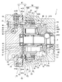
- FIG. 2 is a longitudinal sectional view of the piston motor.
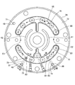
- 3 is a cross-sectional view taken along line III-III in FIG.
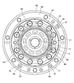
- FIG. 4 is a rear view of the base plate taken along line IV-IV in FIG.
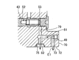
- FIG. 5 is a front view of the casing along the line VV in FIG. 6 is a cross-sectional view of the base plate taken along line VI-VI in FIG.
- FIG. 7 is a cross-sectional view of the base plate taken along line VII-VII in FIG.
- FIG. 1 to 7 show a piston motor 1 constituting a vehicle travel device as an example of a hydraulic motor to which the present invention is applied.
- a load roller, a hydraulic excavator, and the like are equipped with a hydrostatic pressure transmission device (HST) that transmits engine power to a traveling device by hydraulic pressure.
- the hydrostatic transmission device includes a variable displacement type piston pump (not shown) as a hydraulic source driven by an engine, and a variable displacement type piston motor 1 as a hydraulic motor for driving wheels.
- hydraulic fluid circulates between the piston pump and the piston motor 1.
- Piston motor 1 uses hydraulic oil as the working fluid.
- a hydraulic fluid such as a water-soluble alternative liquid may be used.
- FIG. 1 is a hydraulic circuit diagram provided in the piston motor 1.
- the piston motor 1 includes a motor mechanism 40 that is rotated by operating hydraulic pressure, and first and second motor passages 41 and 42 that supply and discharge hydraulic oil to and from the motor mechanism 40.
- the first and second motor passages 41 and 42 are connected to a hydraulic source (not shown) to form a closed circuit of the hydrostatic transmission device.
- the piston motor 1 rotates in the counterclockwise direction when the pressure P1 of the hydraulic fluid guided to the first motor passage 41 from the hydraulic source is increased higher than the pressure P2 of the hydraulic fluid guided to the second motor passage 42.
- the piston motor 1 is rotated in the clockwise direction when the pressure P2 of the hydraulic oil guided from the hydraulic pressure source to the second motor passage 42 is higher than the pressure P1 of the hydraulic fluid guided to the first motor passage 41. .
- the piston motor 1 includes a pair of tilting actuators 31 as a variable capacity mechanism that changes the capacity (pushing capacity) of the motor mechanism 40.
- the tilting actuator 31 is operated by the hydraulic pressure guided through the actuator passage 32 and the actuator passage 33.
- the piston motor 1 includes a speed switching valve 43 that switches the operating hydraulic pressure guided to the tilting actuator 31.
- the speed switching valve 43 has a low speed position a that connects the actuator passage 32 and the actuator passage 33 to the in-motor drain passage 49, and a high speed that connects the actuator passage 32 and the actuator passage 33 to the first and second motor passages 41 and 42, respectively. Position b.
- the hydraulic pressure discharged from a charge pump (not shown) provided in the hydraulic pressure source is guided to the speed switching valve 43 through the speed switching pilot pressure passage 44.
- the hydraulic pressure of the hydraulic fluid guided through the speed switching pilot pressure passage 44 becomes a pilot pressure P3 for switching the positions a and b of the speed switching valve 43.
- the charge pump provided in the hydraulic power source is driven by an engine or the like.
- the speed switching valve 43 is switched to the low speed position a.
- the drain pressure Dr is guided to the tilting actuator 31 through the in-motor drain passage 49.
- the sum of the propulsive force due to the drain pressure Dr and the propulsive force due to the second-speed spring 23 (see FIG. 2) is transmitted through the swash plate 7 (see FIG. 2) due to the operating pressure of the piston 6 (see FIG. 2).
- the tilting actuator 31 is pulled. Therefore, the capacity of the motor mechanism 40 is increased.
- the speed switching valve 43 is switched to the high speed position b.
- the motor driving pressures P1 and P2 are guided to the tilting actuator 31 from the first and second motor passages 41 and 42, respectively.
- the tilting actuator 31 is extended by the motor driving pressure P1 or P2. Therefore, the tilt angle of the swash plate 7 (see FIG. 2) is reduced, and the capacity of the motor mechanism 40 is reduced.
- the piston motor 1 includes a parking brake 20 that automatically brakes that the motor mechanism 40 is rotated by an external force after the vehicle stops traveling.
- the parking brake 20 includes a brake mechanism 25 that brakes the rotation of the motor mechanism 40 by the biasing force of the brake spring 26 when the rotation of the motor mechanism 40 stops, and a brake release actuator that releases the braking of the brake mechanism 25 when the motor mechanism 40 rotates. 29.
- the brake release actuator 29 is operated by the brake release pressure Pp guided from the brake release pressure passage 48 to the brake release pressure chamber 28.
- a hydraulic pressure discharged from a charge pump provided in the hydraulic pressure source is guided to the brake release pressure passage 48.
- the brake release pressure passage 48 may be configured such that hydraulic oil discharged from a piston pump that constitutes a hydrostatic transmission device provided in the hydraulic pressure source is guided. Further, the brake release pressure passage 48 may be configured so that the tank pressure and the hydraulic pressure from the hydraulic pressure source are selectively guided through a switching valve (not shown).
- the throttle 30 is interposed in the brake release pressure passage 48. This restriction 30 reduces the pressure fluctuation in the brake release pressure chamber 28.
- the brake release actuator 29 operates in the contracting direction against the urging force of the brake spring 26, and the braking of the brake mechanism 25 is released.
- a casing chamber 58 that houses the motor mechanism 40 and the parking brake 20 is provided in the casing 59 of the piston motor 1.
- a drain passage 39 connecting the casing chamber 58 and the tank is provided.
- an in-motor drain passage 49 formed in the casing 59 and an out-motor drain passage (not shown) connected to the casing 59 are provided.
- an oil cooler for cooling the working oil
- an oil filter for filtering the working oil
- a flushing passage 47 is connected to the first and second motor passages 41 and 42 via a low pressure selection valve 45 in order to cool the hydraulic fluid circulating in the closed circuit connecting the motor mechanism 40 and the hydraulic power source.
- a relief valve 46 is interposed in the flushing passage 47.
- the low pressure selection valve 45 includes a position a for connecting the second motor passage 42 to the flushing passage 47, a position b for connecting the first motor passage 41 to the flushing passage 47, and the first and second motor passages 41 and 42 and the flushing. A position c that blocks communication with the passage 47. The low pressure selection valve 45 is switched according to the pressure difference between the first and second motor passages 41 and 42.
- the low pressure selection valve 45 is switched to position a.
- the low pressure selection valve 45 is switched to the position b.
- the hydraulic fluid that is returned to the tank through the drain passage outside the motor is dissipated by an oil cooler that is interposed in the drain passage outside the motor. Thereby, the temperature of the hydraulic oil stored in the tank is kept low.
- a hydraulic source (not shown) is configured to fill the closed circuit (first and second motor passages 41 and 42) of the motor mechanism 40 with hydraulic oil sucked from the tank by the charge pump.
- the first and second motor passages 41 and 42 are replenished with relatively low temperature hydraulic oil from the tank. Therefore, the temperature rise of the hydraulic oil circulating through the motor mechanism 40 is suppressed.
- the vehicle travel device is provided with a speed reducer adjacent to the casing 59 of the piston motor 1, and this speed reducer reduces the rotation of the motor mechanism 40 and drives a wheel (drum) (not shown).
- a speed reducer adjacent to the casing 59 of the piston motor 1, and this speed reducer reduces the rotation of the motor mechanism 40 and drives a wheel (drum) (not shown).
- the temperature of the speed reducer rises, and the casing 59 of the piston motor 1 is heated by the speed reducer. The Therefore, it is necessary to prevent the bearing 17 and the oil seal 37 (see FIG. 2) interposed in the casing 59 from being overheated.
- the flushing passage 47 is connected to the casing chamber 58 that houses the motor mechanism 40 of the piston motor 1, and the hydraulic oil that flows out of the flushing passage 47 is guided to the casing chamber 58. .
- the hydraulic oil flowing out from the flushing passage 47 circulates through the casing chamber 58 to absorb the heat of the casing 59, and the casing 59 is cooled.
- the speed reducer adjacent to the casing 59 can also be cooled, and the temperature rise of the speed reducer can be suppressed.
- FIG. 2 is a longitudinal sectional view of the piston motor 1.
- the piston motor 1 includes a case 60 and a base plate 70 as a casing 59.
- a casing chamber 58 is defined between the case 60 and the base plate 70.
- the casing chamber 58 accommodates the motor mechanism 40 and the parking brake 20.
- one end of the output shaft 2 is rotatably supported by the case 60 via the bearing 17, and the other end of the output shaft 2 is rotatably supported by the base plate 70 via the bearing 18.
- the case 60 has a cylindrical case side part 60A and a disk-like case bottom part 60B.
- a case opening 60C is formed at the center of the case bottom 60B.
- One end of the output shaft 2 faces the case opening 60C.
- One end of the output shaft 2 is connected to the input shaft of the speed reducer, and the power of the output shaft 2 is taken out.
- An oil seal 37 is interposed between the case opening 60 ⁇ / b> C and the output shaft 2.
- the casing chamber 58 is sealed with an oil seal 37.
- the motor mechanism 40 includes an output shaft 2 and a cylinder block 3 that rotates integrally with the output shaft 2.
- a plurality of cylinders 4 are formed in the cylinder block 3.
- Each cylinder 4 extends in parallel with the output shaft 2 and is arranged side by side on substantially the same circumference around the output shaft 2.
- a piston 6 is inserted into each cylinder 4.
- a volume chamber 5 is defined between the cylinder 4 and the piston 6.
- a shoe 9 is rotatably connected to the tip of each piston 6 via a spherical seat 10. As the cylinder block 3 rotates, each shoe 9 comes into sliding contact with the swash plate 7, and each piston 6 reciprocates with a stroke amount corresponding to the tilt angle of the swash plate 7.
- a valve plate 8 is interposed between the case 60 and the base plate 70.
- the valve plate 8 has two ports 91 communicating with a hydraulic source (not shown).
- a port 90 (see FIG. 5) that communicates with each volume chamber 5 opens at the end face of the cylinder block 3.
- Each piston 6 protrudes from the cylinder 4 by operating hydraulic pressure guided from the hydraulic pressure source to each volume chamber 5 via each port 91, 90, and each piston 6 pushes the swash plate 7 via the shoe 9. 3 rotates.
- the case bottom 60B is provided with a pair of balls (support shafts) 34 that support the swash plate 7 so that the swash plate 7 can be tilted about the tilt shaft, and a pair of tilt actuators 31 that press the back side of the swash plate 7. It is done.
- FIG. 3 is a sectional view taken along line III-III in FIG.
- a speed switching valve 43 is interposed in the base plate 70. As described above, the speed switching valve 43 switches the pilot pressure Ps guided to the tilting actuator 31.
- the brake mechanism 25 of the parking brake 20 includes three brake disks 21 that rotate together with the cylinder block 3, two friction plates 22 that are attached to the case 60, and the brake disk 21 that is the friction plate 22. And a brake spring 26 that presses against.
- Each annular brake disc 21 is formed with a plurality of teeth 21 ⁇ / b> A aligned in the circumferential direction at the inner peripheral end thereof.
- a spline 19 extending in the axial direction is formed on the outer periphery of the cylinder block 3.
- Each of the brake disks 21 rotates with the cylinder block 3 when the teeth 21 ⁇ / b> A mesh with the spline 19, and is supported so as to be movable in the direction of the rotation axis of the cylinder block 3.
- the brake release actuator 29 releases the braking of the parking brake 20 against the pressing force of the brake spring 26.
- the brake release actuator 29 includes an annular brake piston 27 that is supported so as to be movable in the axial direction with respect to the case 60, and a brake release pressure that is guided by a brake release pressure Pp that drives the brake piston 27 against the brake spring 26. Chamber 28.
- a plurality of spring receiving recesses 88 (see FIG. 5) on which the brake spring 26 is seated are formed on the end surface of the brake piston 27.
- a collar 38 is attached to the inner wall of the case side portion 60A.
- a brake piston 27 is slidably fitted inside the collar 38.
- the brake release pressure chamber 28 is defined as an annular space between the brake piston 27 and the collar 38.
- a brake release pressure Pp is introduced into the brake release pressure chamber 28 from a brake release pressure passage 48 (see FIG. 1) formed in the base plate 70.
- the brake disc 21 When the vehicle is stopped, the brake disc 21 is pressed against the friction plate 22 by the urging force of the brake spring 26 when the brake release pressure Pp guided to the brake release pressure chamber 28 is reduced. Thereby, the rotation of the cylinder block 3 is braked by the frictional force acting on the brake disc 21.
- a low pressure selection valve 45 and a relief valve 46 are interposed in the base plate 70.
- the low pressure selection valve 45 is switched so as to connect the low pressure side of the first and second motor passages 41 and 42 to the flushing passage 47 as described above.
- the relief valve 46 opens and closes the flushing passage 47 according to the outlet pressure of the low pressure selection valve 45.
- the spool 35 of the relief valve 46 is held in the closed position as shown in FIG. 3 when the outlet pressure of the low pressure selection valve 45 is not more than a predetermined value.
- the flushing passage 47 is configured to communicate with the casing chamber 58 and guide the flowing hydraulic oil to the casing chamber 58.
- the relief valve 46 is opened by moving the spool 35 upward in FIGS. 2 and 3 against the urging force of the spring 36.
- the hydraulic oil discharged from the low pressure selection valve 45 is flushed as indicated by the flow line (two-dot chain line) D in FIG. It is guided to the casing chamber 58 through the passage 47.
- the low pressure selection valve 45 and the relief valve 46 are set to open by the pressure generated on the low pressure side of the first and second motor passages 41 and 42, respectively. .
- the hydraulic oil taken out from one of the first and second motor passages 41 and 42 flows into the casing chamber 58 through the flushing passage 47, and this operation is performed.
- the casing chamber 58 is sufficiently cooled by oil regardless of the operating conditions.
- the flushing passage 47 is defined by a base side flushing through hole 71 formed in the base plate 70 and a case side flushing through hole 61 formed in the case 60, as indicated by a broken line in FIG.
- FIG. 4 is a view taken along line IV-IV in FIG. As shown in FIG. 4, a base-side flushing through hole 71 opens in the flange end surface 72 of the base plate 70.
- FIG. 5 is a view taken along line VV in FIG. As shown in FIG. 5, a case side flushing through hole 61 is opened in the flange end surface 62 of the case 60. An annular recess 63 is formed around the case side flushing through hole 61. A seal ring is interposed between the annular recess 63 and the flange end surface 72 of the base plate 70 to seal the two.
- the passage length of the flushing passage 47 is arbitrarily set, and is configured such that the flow rate of the hydraulic oil taken out from one of the first and second motor passages 41 and 42 to the flushing passage 47 can be obtained appropriately.
- the flow resistance that the flushing passage 47 imparts to the flow of the hydraulic oil increases as the viscosity of the hydraulic oil increases. Accordingly, the flow rate of the hydraulic oil is appropriately reduced.
- the flow path resistance imparted to the flow of hydraulic oil by the flushing passage 47 decreases as the viscosity of the hydraulic oil decreases. Therefore, the flow rate of the hydraulic oil is gradually increased, and the temperature rise of the hydraulic oil is suppressed.
- the outlet 47A of the flushing passage 47 opens on the inner wall surface of the case side portion 60A.
- the outlet 47A is located in the vicinity of the case bottom 60B, and opens to face the outer peripheral surface 7A of the swash plate 7.
- the outlet 47A is directed to a swash plate rear space 64 defined between the swash plate 7 and the case bottom 60B, and the hydraulic fluid flowing out from the outlet 47A is guided to the swash plate rear space 64.
- the hydraulic oil flowing into the casing chamber 58 from the outlet 47A flows along the swash plate 7, the inner wall surface of the case bottom 60B and the bearing 17, and the case bottom 60B and the bearing 17 are effectively cooled.
- the flushing passage 47 is formed so as to pass in the vicinity of the bearing 17 and the oil seal 37 in the case bottom portion 60B, the heat of the case bottom portion 60B is absorbed by the hydraulic oil flowing through the flushing passage 47, and the bearing 17 and You may comprise so that the oil seal 37 may be cooled.
- the casing chamber 58 is partitioned into a swash plate storage chamber 58A and a brake front chamber 58B by the brake disc 21 and the friction plate 22 of the parking brake 20.
- An outlet 47A of the flushing passage 47 opens into a swash plate accommodation chamber 58A that accommodates the swash plate 7. The hydraulic oil flowing in from the outlet 47A is guided to the space behind the swash plate 64.
- the hydraulic oil that has flowed into the casing chamber 58 is returned to the tank through the motor drain passage 49 and the motor drain passage, as described above.
- the in-motor drain passage 49 is defined by first and second drain through holes 67 and 68 (see FIG. 5) formed in the case side portion 60A.
- the first and second drain through holes 67 and 68 open to the inner wall surface of the case side portion 60 ⁇ / b> A as a drain inlet through which hydraulic fluid flows out from the casing chamber 58 into the motor drain passage 49.
- An inlet 67A which is an opening end of the first drain passage hole 67, is opened to a swash plate housing chamber 58A that houses the swash plate 7, and is formed at a position facing the outlet 47A across the swash plate 7.
- the opening end (not shown) of the second drain passage hole 68 is formed at a position facing the outlet 47A with the swash plate 7 interposed therebetween.
- the flange end surface 62 of the case 60 has first and second drain through holes 67 and 68 that define an in-motor drain passage 49.
- Annular recesses 77 and 78 are formed around the first and second drain through holes 67 and 68, respectively.
- a seal ring is interposed between the annular recesses 77 and 78 and the flange end surface 72 of the base plate 70 to seal the two.
- drain grooves 75 and 76 are opened in the flange end surface 72 of the base plate 70.
- the drain grooves 75 and 76 extend in an arc shape so as to face the brake piston 27.
- a plurality of spring receiving recesses 80 on which the brake spring 26 is seated are formed on the inner walls of the drain grooves 75 and 76.
- FIG. 6 is a cross-sectional view taken along line VI-VI in FIG. As shown in FIG. 6, the through hole 73 communicates with the drain groove 75 through the through holes 81 and 82.
- the through hole 82 is formed coaxially with the through hole 79 connected to the speed switching valve 43.
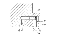
- FIG. 7 is a sectional view taken along line VII-VII in FIG. As shown in FIG. 7, the through hole 74 communicates with the drain groove 76 through the through holes 83 and 84.
- a through hole 85 that defines a drain passage 49 in the motor is opened.
- One end of the through hole 85 opens in the outer wall surface of the base plate 70.
- a motor external drain passage is connected to one end of the through hole 85.
- the hydraulic fluid in the casing chamber 58 flows out through the motor drain passage 49 as shown by streamlines (two-dot chain lines) E1 and E2 in FIGS.
- the in-motor drain passage 49 creates two systems of hydraulic oil flow E1, E2 from the case 60 to the base plate 70 by the first and second drain through holes 67, 68. In contrast, a sufficient flow path cross-sectional area is ensured. Thereby, the pressure rise of the casing chamber 58 is suppressed and the operation of the parking brake 20 is maintained.
- the present invention is not limited to this, and the in-motor drain passage 49 may be configured to increase the number of drain through holes to generate three or more hydraulic fluid flows.
- the piston motor 1 includes a motor mechanism 40 that is rotated by hydraulic fluid supplied and discharged through one of the first motor passage 41 and the second motor passage 42 from the hydraulic fluid pressure source.
- the piston motor 1 communicates with a casing 59 that defines a casing chamber 58 that houses the motor mechanism 40, and the casing chamber 58, and a part of the hydraulic fluid from the low pressure side of the first motor passage 41 and the second motor passage 42.
- a flushing passage 47 that guides it to the casing chamber 58 (see FIGS. 1 to 7).
- the motor mechanism 40 is rotated with respect to the swash plate 7 by the reciprocating motion of the piston 6, the swash plate 7 provided in the casing chamber 58, a plurality of pistons 6 that reciprocate following the swash plate 7 by hydraulic pressure. And the output shaft 2 that outputs the rotation of the cylinder block 3.
- the casing 59 includes a base plate 70 provided with the first motor passage 41 and the second motor passage 42, and a case 60 that supports the output shaft 2 and defines the casing chamber 58 together with the base plate 70.
- the flushing passage 47 is defined by a base side flushing through hole 71 formed in the base plate 70 and a case side flushing through hole 61 formed in the case 60 and communicating with the base side flushing through hole 71 (FIG. 1). To 5).
- the flushing passage 47 extends over the base plate 70 and the case 60, and the working fluid branched from the first and second motor passages 41 and 42 is located in the back of the casing chamber 58 (in the vicinity of the case bottom 60B). It becomes possible to flow into. Thereby, when the part (case bottom part 60B) apart from the base plate 70 of the case 60 is heated by the reduction gear, the case 60 is sufficiently cooled.
- the piston motor 1 includes a brake disk 21 that rotates together with the cylinder block 3 and a drain passage 39 that discharges the hydraulic fluid in the casing chamber 58.
- a swash plate housing chamber 58A for housing the swash plate 7 and a brake front chamber 58B partitioned from the swash plate housing chamber 58A by the brake disc 21 are defined.
- the outlet 47A of the flushing passage 47 and the inlet 67A of the drain passage 39 respectively open into the swash plate accommodation chamber 58A (see FIGS. 1 to 5).
- the hydraulic fluid from the outlet 47 ⁇ / b> A of the flushing passage 47 toward the inlet 67 ⁇ / b> A of the drain passage 39 in the casing chamber 58 passes through the swash plate storage chamber 58 ⁇ / b> A that stores the swash plate 7 and does not cross the brake disk 21. . Therefore, the resistance applied by the rotating brake disc 21 is reduced, and the flow rate of the working fluid circulating in the casing chamber 58 is sufficiently obtained.
- the drain passage 39 is defined by a plurality of drain through holes 67 and 68 that open to the casing chamber 58 (see FIGS. 1 to 5).
- the drain passage 39 generates a plurality of systems of the hydraulic fluid flows E1 and E2 by the plurality of drain passage holes 67 and 68, and therefore, the flow passage is sufficient for the hydraulic fluid flowing out from the casing chamber 58. Area is secured. Thereby, the pressure rise in the casing chamber 58 is suppressed, and the operation of the brake mechanism 25 (parking brake 20) that applies frictional force to the brake disc 21 is maintained.
Landscapes
- Engineering & Computer Science (AREA)
- Mechanical Engineering (AREA)
- General Engineering & Computer Science (AREA)
- Chemical & Material Sciences (AREA)
- Combustion & Propulsion (AREA)
- Hydraulic Motors (AREA)
Abstract
Description
Claims (4)
- 作動液圧源から第一モータ通路と第二モータ通路との一方を通じて給排される作動液によって回転作動するモータ機構を備える液圧モータであって、
前記モータ機構を収容するケーシング室を画成するケーシングと、
前記ケーシング室に連通し、前記第一モータ通路と前記第二モータ通路とのうち低圧側から作動液の一部を取り出して前記ケーシング室に導くフラッシング通路と、を備える液圧モータ。 - 請求項1に記載の液圧モータであって、
前記モータ機構は、
前記ケーシング室内に設けられる斜板と、
作動液圧によって前記斜板に追従して往復動する複数のピストンと、
前記ピストンの往復動によって前記斜板に対して回転するシリンダブロックと、
前記シリンダブロックの回転を出力する出力軸と、を備え、
前記ケーシングは、
前記第一モータ通路及び前記第二モータ通路が設けられるベースプレートと、
前記出力軸を支持し、前記ベースプレートとともに前記ケーシング室を画成するケースと、を備え、
前記フラッシング通路は、
前記ベースプレートに形成されるベース側フラッシング通孔と、
前記ケースに形成され、前記ベース側フラッシング通孔と連通するケース側フラッシング通孔と、によって画成される液圧モータ。 - 請求項2に記載の液圧モータであって、
前記シリンダブロックとともに回転するブレーキディスクと、
前記ケーシング室の作動液を排出するドレン通路と、を備え、
前記ケーシング室には、
前記斜板を収容する斜板収容室と、
前記ブレーキディスクによって前記斜板収容室と仕切られるブレーキ前室と、が画成され、
前記フラッシング通路の出口と前記ドレン通路の入口とは、それぞれ前記斜板収容室に開口する液圧モータ。 - 請求項3に記載の液圧モータであって、
前記ドレン通路は、前記ケーシング室に開口する複数のドレン通孔によって画成される液圧モータ。
Priority Applications (4)
| Application Number | Priority Date | Filing Date | Title |
|---|---|---|---|
| US14/372,942 US10233900B2 (en) | 2012-02-22 | 2013-02-14 | Hydraulic motor system |
| EP13752104.3A EP2806154B1 (en) | 2012-02-22 | 2013-02-14 | Hydraulic motor |
| KR1020147021141A KR101599174B1 (ko) | 2012-02-22 | 2013-02-14 | 액압 모터 |
| CN201380005809.7A CN104053901B (zh) | 2012-02-22 | 2013-02-14 | 液压马达 |
Applications Claiming Priority (2)
| Application Number | Priority Date | Filing Date | Title |
|---|---|---|---|
| JP2012-036218 | 2012-02-22 | ||
| JP2012036218A JP5891064B2 (ja) | 2012-02-22 | 2012-02-22 | 液圧モータ |
Publications (1)
| Publication Number | Publication Date |
|---|---|
| WO2013125432A1 true WO2013125432A1 (ja) | 2013-08-29 |
Family
ID=49005619
Family Applications (1)
| Application Number | Title | Priority Date | Filing Date |
|---|---|---|---|
| PCT/JP2013/053497 WO2013125432A1 (ja) | 2012-02-22 | 2013-02-14 | 液圧モータ |
Country Status (6)
| Country | Link |
|---|---|
| US (1) | US10233900B2 (ja) |
| EP (1) | EP2806154B1 (ja) |
| JP (1) | JP5891064B2 (ja) |
| KR (1) | KR101599174B1 (ja) |
| CN (1) | CN104053901B (ja) |
| WO (1) | WO2013125432A1 (ja) |
Families Citing this family (7)
| Publication number | Priority date | Publication date | Assignee | Title |
|---|---|---|---|---|
| JP2016183621A (ja) * | 2015-03-26 | 2016-10-20 | Kyb株式会社 | 液圧モータ、そのブレーキ装置及びブレーキ装置の製造方法 |
| CN106050819A (zh) * | 2016-07-29 | 2016-10-26 | 柳州柳工挖掘机有限公司 | 工程机械行走马达壳体冲洗油路 |
| JP7049222B2 (ja) * | 2018-09-10 | 2022-04-06 | Kyb株式会社 | ブレーキシステム及びこれを備える液圧モータ |
| JP7153539B2 (ja) * | 2018-11-26 | 2022-10-14 | Kyb株式会社 | 流体圧駆動装置 |
| JP7281918B2 (ja) * | 2019-02-18 | 2023-05-26 | ナブテスコ株式会社 | 油圧モータ |
| CN110159618A (zh) * | 2019-06-28 | 2019-08-23 | 无锡市钻通工程机械有限公司 | 一种液压闭式冲洗回路 |
| FR3105309B1 (fr) * | 2019-12-20 | 2021-12-10 | Poclain Hydraulics Ind | Machine hydraulique comprenant un organe de défreinage |
Citations (5)
| Publication number | Priority date | Publication date | Assignee | Title |
|---|---|---|---|---|
| JP3485585B2 (ja) * | 1991-08-28 | 2004-01-13 | ハイドロマチック ゲゼルシャフト ミット べシュレンクテル ハフツング | 排油排出装置付油圧機械 |
| JP2004060508A (ja) | 2002-07-29 | 2004-02-26 | Kayaba Ind Co Ltd | 液圧モータ |
| JP2006161453A (ja) | 2004-12-08 | 2006-06-22 | Chugoku Electric Power Co Inc:The | 瓦棒葺き屋根の改修工法 |
| JP4301758B2 (ja) * | 2001-01-31 | 2009-07-22 | ポクラン イドロリク アンドゥストリ | 閉回路用補充装置 |
| JP4540750B1 (ja) * | 2010-06-01 | 2010-09-08 | 株式会社小坂研究所 | サブマージドポンプ駆動用オイルモータの冷却機構 |
Family Cites Families (18)
| Publication number | Priority date | Publication date | Assignee | Title |
|---|---|---|---|---|
| US3089426A (en) * | 1958-09-17 | 1963-05-14 | New York Air Brake Co | Engine |
| US2961829A (en) * | 1959-10-15 | 1960-11-29 | New York Air Brake Co | Hydraulic transmission |
| US3181477A (en) * | 1961-09-14 | 1965-05-04 | Sperry Rand Corp | Power transmission |
| JP2557283Y2 (ja) | 1990-06-21 | 1997-12-10 | カヤバ工業株式会社 | 二速油圧モータ |
| US5419130A (en) | 1991-08-28 | 1995-05-30 | Hydromatik Gmbh | Hydrostatic machine with drain oil discharge |
| DE4303380A1 (de) * | 1993-02-05 | 1994-08-11 | Sachsenhydraulik Gmbh | Hydrostatische Kolbenmaschine |
| JPH109118A (ja) * | 1996-06-27 | 1998-01-13 | Kubota Corp | 減速機付油圧モータ |
| JP2001020847A (ja) * | 1999-07-08 | 2001-01-23 | Teijin Seiki Co Ltd | 流体モータの制動装置 |
| JP4577969B2 (ja) | 2000-09-26 | 2010-11-10 | 三輪精機株式会社 | 油圧モータ |
| US20040000142A1 (en) * | 2002-06-27 | 2004-01-01 | Hirotaka Nunomura | High-pressure and low-pressure selecting valve and swash-plate type hydraulic motor system |
| JP2004125092A (ja) * | 2002-10-03 | 2004-04-22 | Hitachi Constr Mach Co Ltd | 油圧モータ用減速機の潤滑装置 |
| US20040187491A1 (en) * | 2003-03-26 | 2004-09-30 | Whitaker James S. | Pump with hot oil shuttle valve |
| JP4308205B2 (ja) * | 2004-01-05 | 2009-08-05 | 日立建機株式会社 | 可変容量型油圧ポンプの傾転制御装置 |
| CN101514670A (zh) * | 2008-02-21 | 2009-08-26 | 白华平 | 液压泵式发动机及其制造方法 |
| JP4970357B2 (ja) | 2008-06-11 | 2012-07-04 | 株式会社クボタ | 油圧駆動式モータ装置 |
| JP5087580B2 (ja) * | 2009-03-30 | 2012-12-05 | 住友建機株式会社 | 建設機械の油圧モータ |
| JP5571350B2 (ja) | 2009-10-19 | 2014-08-13 | カヤバ工業株式会社 | 液圧モータ駆動装置 |
| CN201560890U (zh) * | 2009-11-05 | 2010-08-25 | 昆山金发液压机械有限公司 | 平面配油曲轴无连杆液压马达 |
-
2012
- 2012-02-22 JP JP2012036218A patent/JP5891064B2/ja active Active
-
2013
- 2013-02-14 CN CN201380005809.7A patent/CN104053901B/zh active Active
- 2013-02-14 KR KR1020147021141A patent/KR101599174B1/ko active IP Right Grant
- 2013-02-14 WO PCT/JP2013/053497 patent/WO2013125432A1/ja active Application Filing
- 2013-02-14 US US14/372,942 patent/US10233900B2/en active Active
- 2013-02-14 EP EP13752104.3A patent/EP2806154B1/en active Active
Patent Citations (5)
| Publication number | Priority date | Publication date | Assignee | Title |
|---|---|---|---|---|
| JP3485585B2 (ja) * | 1991-08-28 | 2004-01-13 | ハイドロマチック ゲゼルシャフト ミット べシュレンクテル ハフツング | 排油排出装置付油圧機械 |
| JP4301758B2 (ja) * | 2001-01-31 | 2009-07-22 | ポクラン イドロリク アンドゥストリ | 閉回路用補充装置 |
| JP2004060508A (ja) | 2002-07-29 | 2004-02-26 | Kayaba Ind Co Ltd | 液圧モータ |
| JP2006161453A (ja) | 2004-12-08 | 2006-06-22 | Chugoku Electric Power Co Inc:The | 瓦棒葺き屋根の改修工法 |
| JP4540750B1 (ja) * | 2010-06-01 | 2010-09-08 | 株式会社小坂研究所 | サブマージドポンプ駆動用オイルモータの冷却機構 |
Also Published As
| Publication number | Publication date |
|---|---|
| JP2013170536A (ja) | 2013-09-02 |
| EP2806154A1 (en) | 2014-11-26 |
| KR20140105865A (ko) | 2014-09-02 |
| CN104053901B (zh) | 2016-04-20 |
| CN104053901A (zh) | 2014-09-17 |
| US20150000512A1 (en) | 2015-01-01 |
| EP2806154A4 (en) | 2015-12-02 |
| KR101599174B1 (ko) | 2016-03-02 |
| JP5891064B2 (ja) | 2016-03-22 |
| EP2806154B1 (en) | 2019-12-04 |
| US10233900B2 (en) | 2019-03-19 |
Similar Documents
| Publication | Publication Date | Title |
|---|---|---|
| WO2013125432A1 (ja) | 液圧モータ | |
| US8056670B2 (en) | Pump unit and working vehicle | |
| JP6715268B2 (ja) | 車両に搭載される油圧アシスト装置及びこれを放圧する方法 | |
| JP5948081B2 (ja) | 液圧モータ | |
| US11274682B2 (en) | Hydraulic driving apparatus | |
| US20060260302A1 (en) | Neutral valve structure | |
| JP4532250B2 (ja) | 減速機付き油圧モータ | |
| JP4132926B2 (ja) | ポンプユニット及び作業車 | |
| US7299888B2 (en) | Pump unit and working vehicle | |
| JP4970357B2 (ja) | 油圧駆動式モータ装置 | |
| JP4516878B2 (ja) | アクスル装置 | |
| JP2018096520A (ja) | ダンプトラックの湿式ブレーキ装置 | |
| JP4714926B2 (ja) | ポンプユニット | |
| JP2009216125A (ja) | 動力断続機 | |
| JP6142167B2 (ja) | 油圧機械式無段変速機 | |
| US7497081B2 (en) | Hydraulic fluid supply structure | |
| JP5702156B2 (ja) | タンデムポンプユニット及び作業車輌 | |
| JP4963639B2 (ja) | 油圧モータのブレーキシステム | |
| JPH0988904A (ja) | ブレーキ装置を有する油圧モータ | |
| JP2002013636A (ja) | 流体圧伝動装置 | |
| JP2007302146A (ja) | トランスミッション | |
| JP2007303580A (ja) | アキシャルピストン装置 |
Legal Events
| Date | Code | Title | Description |
|---|---|---|---|
| WWE | Wipo information: entry into national phase |
Ref document number: 201380005809.7 Country of ref document: CN |
|
| 121 | Ep: the epo has been informed by wipo that ep was designated in this application |
Ref document number: 13752104 Country of ref document: EP Kind code of ref document: A1 |
|
| WWE | Wipo information: entry into national phase |
Ref document number: 14372942 Country of ref document: US |
|
| WWE | Wipo information: entry into national phase |
Ref document number: 2013752104 Country of ref document: EP |
|
| ENP | Entry into the national phase |
Ref document number: 20147021141 Country of ref document: KR Kind code of ref document: A |
|
| NENP | Non-entry into the national phase |
Ref country code: DE |