WO2013108813A1 - 内燃エンジン始動制御装置 - Google Patents
内燃エンジン始動制御装置 Download PDFInfo
- Publication number
- WO2013108813A1 WO2013108813A1 PCT/JP2013/050751 JP2013050751W WO2013108813A1 WO 2013108813 A1 WO2013108813 A1 WO 2013108813A1 JP 2013050751 W JP2013050751 W JP 2013050751W WO 2013108813 A1 WO2013108813 A1 WO 2013108813A1
- Authority
- WO
- WIPO (PCT)
- Prior art keywords
- internal combustion
- combustion engine
- learning
- intake air
- air amount
- Prior art date
Links
Images

Classifications
-
- F—MECHANICAL ENGINEERING; LIGHTING; HEATING; WEAPONS; BLASTING
- F02—COMBUSTION ENGINES; HOT-GAS OR COMBUSTION-PRODUCT ENGINE PLANTS
- F02D—CONTROLLING COMBUSTION ENGINES
- F02D41/00—Electrical control of supply of combustible mixture or its constituents
- F02D41/0002—Controlling intake air
-
- B—PERFORMING OPERATIONS; TRANSPORTING
- B60—VEHICLES IN GENERAL
- B60K—ARRANGEMENT OR MOUNTING OF PROPULSION UNITS OR OF TRANSMISSIONS IN VEHICLES; ARRANGEMENT OR MOUNTING OF PLURAL DIVERSE PRIME-MOVERS IN VEHICLES; AUXILIARY DRIVES FOR VEHICLES; INSTRUMENTATION OR DASHBOARDS FOR VEHICLES; ARRANGEMENTS IN CONNECTION WITH COOLING, AIR INTAKE, GAS EXHAUST OR FUEL SUPPLY OF PROPULSION UNITS IN VEHICLES
- B60K6/00—Arrangement or mounting of plural diverse prime-movers for mutual or common propulsion, e.g. hybrid propulsion systems comprising electric motors and internal combustion engines ; Control systems therefor, i.e. systems controlling two or more prime movers, or controlling one of these prime movers and any of the transmission, drive or drive units Informative references: mechanical gearings with secondary electric drive F16H3/72; arrangements for handling mechanical energy structurally associated with the dynamo-electric machine H02K7/00; machines comprising structurally interrelated motor and generator parts H02K51/00; dynamo-electric machines not otherwise provided for in H02K see H02K99/00
- B60K6/20—Arrangement or mounting of plural diverse prime-movers for mutual or common propulsion, e.g. hybrid propulsion systems comprising electric motors and internal combustion engines ; Control systems therefor, i.e. systems controlling two or more prime movers, or controlling one of these prime movers and any of the transmission, drive or drive units Informative references: mechanical gearings with secondary electric drive F16H3/72; arrangements for handling mechanical energy structurally associated with the dynamo-electric machine H02K7/00; machines comprising structurally interrelated motor and generator parts H02K51/00; dynamo-electric machines not otherwise provided for in H02K see H02K99/00 the prime-movers consisting of electric motors and internal combustion engines, e.g. HEVs
- B60K6/42—Arrangement or mounting of plural diverse prime-movers for mutual or common propulsion, e.g. hybrid propulsion systems comprising electric motors and internal combustion engines ; Control systems therefor, i.e. systems controlling two or more prime movers, or controlling one of these prime movers and any of the transmission, drive or drive units Informative references: mechanical gearings with secondary electric drive F16H3/72; arrangements for handling mechanical energy structurally associated with the dynamo-electric machine H02K7/00; machines comprising structurally interrelated motor and generator parts H02K51/00; dynamo-electric machines not otherwise provided for in H02K see H02K99/00 the prime-movers consisting of electric motors and internal combustion engines, e.g. HEVs characterised by the architecture of the hybrid electric vehicle
- B60K6/48—Parallel type
-
- B—PERFORMING OPERATIONS; TRANSPORTING
- B60—VEHICLES IN GENERAL
- B60W—CONJOINT CONTROL OF VEHICLE SUB-UNITS OF DIFFERENT TYPE OR DIFFERENT FUNCTION; CONTROL SYSTEMS SPECIALLY ADAPTED FOR HYBRID VEHICLES; ROAD VEHICLE DRIVE CONTROL SYSTEMS FOR PURPOSES NOT RELATED TO THE CONTROL OF A PARTICULAR SUB-UNIT
- B60W10/00—Conjoint control of vehicle sub-units of different type or different function
- B60W10/02—Conjoint control of vehicle sub-units of different type or different function including control of driveline clutches
-
- B—PERFORMING OPERATIONS; TRANSPORTING
- B60—VEHICLES IN GENERAL
- B60W—CONJOINT CONTROL OF VEHICLE SUB-UNITS OF DIFFERENT TYPE OR DIFFERENT FUNCTION; CONTROL SYSTEMS SPECIALLY ADAPTED FOR HYBRID VEHICLES; ROAD VEHICLE DRIVE CONTROL SYSTEMS FOR PURPOSES NOT RELATED TO THE CONTROL OF A PARTICULAR SUB-UNIT
- B60W10/00—Conjoint control of vehicle sub-units of different type or different function
- B60W10/04—Conjoint control of vehicle sub-units of different type or different function including control of propulsion units
- B60W10/06—Conjoint control of vehicle sub-units of different type or different function including control of propulsion units including control of combustion engines
-
- B—PERFORMING OPERATIONS; TRANSPORTING
- B60—VEHICLES IN GENERAL
- B60W—CONJOINT CONTROL OF VEHICLE SUB-UNITS OF DIFFERENT TYPE OR DIFFERENT FUNCTION; CONTROL SYSTEMS SPECIALLY ADAPTED FOR HYBRID VEHICLES; ROAD VEHICLE DRIVE CONTROL SYSTEMS FOR PURPOSES NOT RELATED TO THE CONTROL OF A PARTICULAR SUB-UNIT
- B60W50/00—Details of control systems for road vehicle drive control not related to the control of a particular sub-unit, e.g. process diagnostic or vehicle driver interfaces
- B60W50/0098—Details of control systems ensuring comfort, safety or stability not otherwise provided for
-
- F—MECHANICAL ENGINEERING; LIGHTING; HEATING; WEAPONS; BLASTING
- F02—COMBUSTION ENGINES; HOT-GAS OR COMBUSTION-PRODUCT ENGINE PLANTS
- F02D—CONTROLLING COMBUSTION ENGINES
- F02D29/00—Controlling engines, such controlling being peculiar to the devices driven thereby, the devices being other than parts or accessories essential to engine operation, e.g. controlling of engines by signals external thereto
- F02D29/02—Controlling engines, such controlling being peculiar to the devices driven thereby, the devices being other than parts or accessories essential to engine operation, e.g. controlling of engines by signals external thereto peculiar to engines driving vehicles; peculiar to engines driving variable pitch propellers
-
- F—MECHANICAL ENGINEERING; LIGHTING; HEATING; WEAPONS; BLASTING
- F02—COMBUSTION ENGINES; HOT-GAS OR COMBUSTION-PRODUCT ENGINE PLANTS
- F02D—CONTROLLING COMBUSTION ENGINES
- F02D41/00—Electrical control of supply of combustible mixture or its constituents
- F02D41/02—Circuit arrangements for generating control signals
- F02D41/04—Introducing corrections for particular operating conditions
- F02D41/06—Introducing corrections for particular operating conditions for engine starting or warming up
- F02D41/062—Introducing corrections for particular operating conditions for engine starting or warming up for starting
-
- F—MECHANICAL ENGINEERING; LIGHTING; HEATING; WEAPONS; BLASTING
- F02—COMBUSTION ENGINES; HOT-GAS OR COMBUSTION-PRODUCT ENGINE PLANTS
- F02D—CONTROLLING COMBUSTION ENGINES
- F02D41/00—Electrical control of supply of combustible mixture or its constituents
- F02D41/02—Circuit arrangements for generating control signals
- F02D41/18—Circuit arrangements for generating control signals by measuring intake air flow
-
- F—MECHANICAL ENGINEERING; LIGHTING; HEATING; WEAPONS; BLASTING
- F02—COMBUSTION ENGINES; HOT-GAS OR COMBUSTION-PRODUCT ENGINE PLANTS
- F02D—CONTROLLING COMBUSTION ENGINES
- F02D41/00—Electrical control of supply of combustible mixture or its constituents
- F02D41/24—Electrical control of supply of combustible mixture or its constituents characterised by the use of digital means
- F02D41/2406—Electrical control of supply of combustible mixture or its constituents characterised by the use of digital means using essentially read only memories
- F02D41/2425—Particular ways of programming the data
- F02D41/2429—Methods of calibrating or learning
- F02D41/2451—Methods of calibrating or learning characterised by what is learned or calibrated
-
- B—PERFORMING OPERATIONS; TRANSPORTING
- B60—VEHICLES IN GENERAL
- B60K—ARRANGEMENT OR MOUNTING OF PROPULSION UNITS OR OF TRANSMISSIONS IN VEHICLES; ARRANGEMENT OR MOUNTING OF PLURAL DIVERSE PRIME-MOVERS IN VEHICLES; AUXILIARY DRIVES FOR VEHICLES; INSTRUMENTATION OR DASHBOARDS FOR VEHICLES; ARRANGEMENTS IN CONNECTION WITH COOLING, AIR INTAKE, GAS EXHAUST OR FUEL SUPPLY OF PROPULSION UNITS IN VEHICLES
- B60K6/00—Arrangement or mounting of plural diverse prime-movers for mutual or common propulsion, e.g. hybrid propulsion systems comprising electric motors and internal combustion engines ; Control systems therefor, i.e. systems controlling two or more prime movers, or controlling one of these prime movers and any of the transmission, drive or drive units Informative references: mechanical gearings with secondary electric drive F16H3/72; arrangements for handling mechanical energy structurally associated with the dynamo-electric machine H02K7/00; machines comprising structurally interrelated motor and generator parts H02K51/00; dynamo-electric machines not otherwise provided for in H02K see H02K99/00
- B60K6/20—Arrangement or mounting of plural diverse prime-movers for mutual or common propulsion, e.g. hybrid propulsion systems comprising electric motors and internal combustion engines ; Control systems therefor, i.e. systems controlling two or more prime movers, or controlling one of these prime movers and any of the transmission, drive or drive units Informative references: mechanical gearings with secondary electric drive F16H3/72; arrangements for handling mechanical energy structurally associated with the dynamo-electric machine H02K7/00; machines comprising structurally interrelated motor and generator parts H02K51/00; dynamo-electric machines not otherwise provided for in H02K see H02K99/00 the prime-movers consisting of electric motors and internal combustion engines, e.g. HEVs
- B60K6/22—Arrangement or mounting of plural diverse prime-movers for mutual or common propulsion, e.g. hybrid propulsion systems comprising electric motors and internal combustion engines ; Control systems therefor, i.e. systems controlling two or more prime movers, or controlling one of these prime movers and any of the transmission, drive or drive units Informative references: mechanical gearings with secondary electric drive F16H3/72; arrangements for handling mechanical energy structurally associated with the dynamo-electric machine H02K7/00; machines comprising structurally interrelated motor and generator parts H02K51/00; dynamo-electric machines not otherwise provided for in H02K see H02K99/00 the prime-movers consisting of electric motors and internal combustion engines, e.g. HEVs characterised by apparatus, components or means specially adapted for HEVs
- B60K6/26—Arrangement or mounting of plural diverse prime-movers for mutual or common propulsion, e.g. hybrid propulsion systems comprising electric motors and internal combustion engines ; Control systems therefor, i.e. systems controlling two or more prime movers, or controlling one of these prime movers and any of the transmission, drive or drive units Informative references: mechanical gearings with secondary electric drive F16H3/72; arrangements for handling mechanical energy structurally associated with the dynamo-electric machine H02K7/00; machines comprising structurally interrelated motor and generator parts H02K51/00; dynamo-electric machines not otherwise provided for in H02K see H02K99/00 the prime-movers consisting of electric motors and internal combustion engines, e.g. HEVs characterised by apparatus, components or means specially adapted for HEVs characterised by the motors or the generators
- B60K2006/268—Electric drive motor starts the engine, i.e. used as starter motor
-
- B—PERFORMING OPERATIONS; TRANSPORTING
- B60—VEHICLES IN GENERAL
- B60K—ARRANGEMENT OR MOUNTING OF PROPULSION UNITS OR OF TRANSMISSIONS IN VEHICLES; ARRANGEMENT OR MOUNTING OF PLURAL DIVERSE PRIME-MOVERS IN VEHICLES; AUXILIARY DRIVES FOR VEHICLES; INSTRUMENTATION OR DASHBOARDS FOR VEHICLES; ARRANGEMENTS IN CONNECTION WITH COOLING, AIR INTAKE, GAS EXHAUST OR FUEL SUPPLY OF PROPULSION UNITS IN VEHICLES
- B60K6/00—Arrangement or mounting of plural diverse prime-movers for mutual or common propulsion, e.g. hybrid propulsion systems comprising electric motors and internal combustion engines ; Control systems therefor, i.e. systems controlling two or more prime movers, or controlling one of these prime movers and any of the transmission, drive or drive units Informative references: mechanical gearings with secondary electric drive F16H3/72; arrangements for handling mechanical energy structurally associated with the dynamo-electric machine H02K7/00; machines comprising structurally interrelated motor and generator parts H02K51/00; dynamo-electric machines not otherwise provided for in H02K see H02K99/00
- B60K6/20—Arrangement or mounting of plural diverse prime-movers for mutual or common propulsion, e.g. hybrid propulsion systems comprising electric motors and internal combustion engines ; Control systems therefor, i.e. systems controlling two or more prime movers, or controlling one of these prime movers and any of the transmission, drive or drive units Informative references: mechanical gearings with secondary electric drive F16H3/72; arrangements for handling mechanical energy structurally associated with the dynamo-electric machine H02K7/00; machines comprising structurally interrelated motor and generator parts H02K51/00; dynamo-electric machines not otherwise provided for in H02K see H02K99/00 the prime-movers consisting of electric motors and internal combustion engines, e.g. HEVs
- B60K6/42—Arrangement or mounting of plural diverse prime-movers for mutual or common propulsion, e.g. hybrid propulsion systems comprising electric motors and internal combustion engines ; Control systems therefor, i.e. systems controlling two or more prime movers, or controlling one of these prime movers and any of the transmission, drive or drive units Informative references: mechanical gearings with secondary electric drive F16H3/72; arrangements for handling mechanical energy structurally associated with the dynamo-electric machine H02K7/00; machines comprising structurally interrelated motor and generator parts H02K51/00; dynamo-electric machines not otherwise provided for in H02K see H02K99/00 the prime-movers consisting of electric motors and internal combustion engines, e.g. HEVs characterised by the architecture of the hybrid electric vehicle
- B60K6/48—Parallel type
- B60K2006/4825—Electric machine connected or connectable to gearbox input shaft
-
- B—PERFORMING OPERATIONS; TRANSPORTING
- B60—VEHICLES IN GENERAL
- B60W—CONJOINT CONTROL OF VEHICLE SUB-UNITS OF DIFFERENT TYPE OR DIFFERENT FUNCTION; CONTROL SYSTEMS SPECIALLY ADAPTED FOR HYBRID VEHICLES; ROAD VEHICLE DRIVE CONTROL SYSTEMS FOR PURPOSES NOT RELATED TO THE CONTROL OF A PARTICULAR SUB-UNIT
- B60W50/00—Details of control systems for road vehicle drive control not related to the control of a particular sub-unit, e.g. process diagnostic or vehicle driver interfaces
- B60W2050/0062—Adapting control system settings
- B60W2050/0075—Automatic parameter input, automatic initialising or calibrating means
- B60W2050/0083—Setting, resetting, calibration
- B60W2050/0088—Adaptive recalibration
-
- F—MECHANICAL ENGINEERING; LIGHTING; HEATING; WEAPONS; BLASTING
- F02—COMBUSTION ENGINES; HOT-GAS OR COMBUSTION-PRODUCT ENGINE PLANTS
- F02D—CONTROLLING COMBUSTION ENGINES
- F02D41/00—Electrical control of supply of combustible mixture or its constituents
- F02D41/02—Circuit arrangements for generating control signals
- F02D41/04—Introducing corrections for particular operating conditions
- F02D41/08—Introducing corrections for particular operating conditions for idling
-
- F—MECHANICAL ENGINEERING; LIGHTING; HEATING; WEAPONS; BLASTING
- F02—COMBUSTION ENGINES; HOT-GAS OR COMBUSTION-PRODUCT ENGINE PLANTS
- F02N—STARTING OF COMBUSTION ENGINES; STARTING AIDS FOR SUCH ENGINES, NOT OTHERWISE PROVIDED FOR
- F02N15/00—Other power-operated starting apparatus; Component parts, details, or accessories, not provided for in, or of interest apart from groups F02N5/00 - F02N13/00
- F02N15/02—Gearing between starting-engines and started engines; Engagement or disengagement thereof
- F02N15/022—Gearing between starting-engines and started engines; Engagement or disengagement thereof the starter comprising an intermediate clutch
-
- Y—GENERAL TAGGING OF NEW TECHNOLOGICAL DEVELOPMENTS; GENERAL TAGGING OF CROSS-SECTIONAL TECHNOLOGIES SPANNING OVER SEVERAL SECTIONS OF THE IPC; TECHNICAL SUBJECTS COVERED BY FORMER USPC CROSS-REFERENCE ART COLLECTIONS [XRACs] AND DIGESTS
- Y02—TECHNOLOGIES OR APPLICATIONS FOR MITIGATION OR ADAPTATION AGAINST CLIMATE CHANGE
- Y02T—CLIMATE CHANGE MITIGATION TECHNOLOGIES RELATED TO TRANSPORTATION
- Y02T10/00—Road transport of goods or passengers
- Y02T10/10—Internal combustion engine [ICE] based vehicles
- Y02T10/40—Engine management systems
-
- Y—GENERAL TAGGING OF NEW TECHNOLOGICAL DEVELOPMENTS; GENERAL TAGGING OF CROSS-SECTIONAL TECHNOLOGIES SPANNING OVER SEVERAL SECTIONS OF THE IPC; TECHNICAL SUBJECTS COVERED BY FORMER USPC CROSS-REFERENCE ART COLLECTIONS [XRACs] AND DIGESTS
- Y02—TECHNOLOGIES OR APPLICATIONS FOR MITIGATION OR ADAPTATION AGAINST CLIMATE CHANGE
- Y02T—CLIMATE CHANGE MITIGATION TECHNOLOGIES RELATED TO TRANSPORTATION
- Y02T10/00—Road transport of goods or passengers
- Y02T10/60—Other road transportation technologies with climate change mitigation effect
- Y02T10/62—Hybrid vehicles
Definitions
- This invention relates to the control of the intake air amount when starting an internal combustion engine.
- the intake air amount of the internal combustion engine is set to the target idle due to product variations and large friction of the internal combustion engine immediately after manufacture.
- the amount equivalent to the rotational speed may not be reached.
- the rotational torque exerted on the internal combustion engine by the electric motor disappears when the clutch is disengaged after cranking. May stall without maintaining idle rotation.
- Japanese Patent Application Laid-Open No. 9-144586 issued in 1997 by the Japan Patent Office proposes a method for quickly stabilizing the rotational speed of an internal combustion engine immediately after the start. This method detects whether the feedback correction amount of the intake air amount of the internal combustion engine is limited by the limiter value, and changes the limiter value or the learning value when the feedback correction amount is limited by the limiter value. .
- This prior art determines that the feedback correction amount is limited by the limiter value when the feedback correction amount sticks to the limiter value for a predetermined time.
- an object of the present invention is to efficiently control the intake air amount during the starting period of the internal combustion engine in the initial state.
- the present invention includes the following programmable controller in an internal combustion engine start control device that starts an internal combustion engine by cranking the internal combustion engine with an electric motor. That is, the programmable controller performs feedback control of the intake air amount of the internal combustion engine to the target idle intake air amount, performs learning of the feedback correction amount applied in the feedback control, and performs intake air amount learning control using the learned value. Programmed to run in parallel with feedback control. The feedback correction amount is regulated by the allowable correction range, and the programmable controller is further programmed to set the allowable correction range applied before learning wider than the allowable correction range applied after the start of learning.
- FIG. 1 is a schematic configuration diagram of a hybrid drive vehicle and an internal combustion engine start control device according to an embodiment of the present invention.
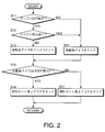
- FIG. 2 is a flowchart illustrating a routine for setting an intake air amount feedback correction allowable value for an internal combustion engine, which is executed by an engine controller according to an embodiment of the present invention.
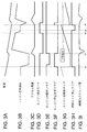
- FIG. 3A to 3F are timing charts for explaining the execution result of the feedback correction allowable value setting routine.
- the hybrid drive vehicle includes an electric motor 1 and an internal combustion engine 2 as a driving power source.
- the electric motor 1 is connected to a drive wheel 7 of a hybrid drive vehicle through a transmission mechanism 4 including an automatic transmission and a clutch, and a differential 5.
- the internal combustion engine 2 is connected to the electric motor 1 via the clutch 3.
- the hybrid drive vehicle travels by transmitting the drive torque of the electric motor 1 to the drive wheels 7 via the speed change mechanism 4 and the differential 5.
- This travel mode is referred to as an EV mode.
- HCU hybrid control unit
- ECU engine control unit
- the ECU 7 and the HCU 8 are each composed of a microcomputer having a central processing unit (CPU), a read-only memory (ROM), a random access memory (RAM), and an input / output interface (I / O interface).
- the ECU 7 can also be composed of a plurality of microcomputers. It is also possible to configure the HCU 8 with a plurality of microcomputers. Alternatively, the ECU 7 and the HCU 8 can be configured by a single microcomputer.
- the control of the internal combustion engine 2 by the ECU 7 includes feedback control and learning control of the intake air amount of the internal combustion engine.
- a rotational speed sensor 9 for detecting the rotational speed of the internal combustion engine 2 and an air flow meter 10 for detecting the intake air amount are connected to the ECU 7 via a signal circuit.
- the internal combustion engine 2 is started by supplying the fuel to the internal combustion engine 2 while the electric motor 1 cranks the internal combustion engine 2 with the clutch 3 engaged.
- the ECU 7 controls the intake air amount and the fuel supply amount so that the rotation speed of the internal combustion engine 2 is stabilized at the idle rotation speed immediately after starting.
- the electric motor 2 cranks the internal combustion engine 2 with the clutch 3 engaged, and the clutch 3 is disconnected after the internal combustion engine 2 is completely exploded.
- the clutch 3 is disconnected, the rotational torque exerted on the internal combustion engine 2 by the electric motor 2 disappears.
- the ECU 7 performs feedback control and learning control of the intake air amount of the internal combustion engine so that the rotational speed of the internal combustion engine 2 stabilizes as quickly as possible to the target idle rotational speed.
- the intake air amount is controlled by changing the throttle opening (not shown) of the internal combustion engine 2.
- the ECU 7 also controls the amount of fuel supplied to the internal combustion engine 2 in accordance with the amount of intake air detected by the air flow meter 10.
- an initial value is usually given as a learning value for feedback correction of the intake air amount.
- an average value of learning values in an internal combustion engine having the same specification is given as the initial value.
- the feedback correction amount becomes relatively large with respect to the initial value of the learning value due to product variations and large friction of the unoperated internal combustion engine 2.
- the internal combustion engine start control device is configured such that the ECU 7 operates as FIG.
- An intake air amount feedback correction allowable value setting routine of the internal combustion engine shown in 2 is executed. This routine is repeatedly executed at regular intervals of, for example, 10 milliseconds during a period from immediately after the start of the internal combustion engine 2 to when it is stopped.
- step S ⁇ b> 10 the ECU 7 determines whether or not learning of an intake air amount correction value for idle rotation speed control of the internal combustion engine 2 is being executed. Specifically, the ECU 7 performs feedback correction of the intake air amount based on the deviation between the target idle rotation speed and the rotation speed of the internal combustion engine 2 detected by the rotation speed sensor 9. The correction amount of the intake air amount by this feedback correction is learned over a certain period, and when the learning is completed, the learned value is fed back to the intake air amount control in the starting control of the internal combustion engine 2 after the next time. Apply prior to.
- learning of the feedback correction amount of the intake air amount for idle rotation speed control is abbreviated as idle speed control (ISC) learning.
- a learning value obtained by learning the feedback correction amount is abbreviated as an ISC learning value.
- a value set to the intake air amount increase side from the average value of the ISC learning value in the internal combustion engine of the same specification is given in advance as the initial value of the ISC learning value. Therefore, when the hybrid drive vehicle is shipped from the factory, the internal combustion engine 2 is started under a throttle opening corresponding to the initial value of the ISC learning value that exceeds the throttle opening corresponding to the average value of the ISC learning value.
- step S10 determines whether ISC learning is currently being performed. In other words, it is determined whether or not the current time corresponds to the above-described certain period. When learning is not being executed, either ISC learning is completed or ISC learning is inexperienced.
- the ECU 7 determines whether or not the ISC learning is inexperienced in step S20.
- the ECU 7 selects a lower limit candidate value LM1 of the feedback correction amount when ISC learning is inexperienced in step S30.
- the lower limit value means the maximum allowable decrease amount when the intake air amount is corrected for decrease.
- the lower limit value is therefore represented by a negative value.
- step S20 determines whether ISC learning has been experienced.
- ECU 7 selects lower limit candidate value LM3 of the feedback correction value in the case where ISC learning has been experienced in step S40.
- the lower limit candidate value LM1 selected in step S30 is larger than the lower limit candidate value LM3 selected in step S40.
- the ECU 7 selects the lower limit candidate value LM2 during the ISC learning in step S50.
- the lower limit candidate value LM2 selected in step S50 is a larger value than the lower limit candidate value LM1 in the case where ISC learning is not experienced given in step S30.
- the setting of the lower limit candidate value LM2 is based on a known technique of expanding the upper and lower limit values of feedback correction during ISC learning.
- step S60 the ECU 7 sets the lower limit candidate value LM1 selected in step S30, the lower limit candidate value LM3 selected in step S40, or the lower limit candidate value LM2 selected in step S50 as the lower limit value LM of the feedback correction amount. After the process of step S60, the ECU 7 ends the routine.
- the feedback correction and learning correction of the intake air amount at the start of the internal combustion engine 2 are determined as described above and the ISC learning value initial value set in advance to exceed the average value of the learning value in the internal combustion engine of the same specification. This is performed under the lower limit value LM of the feedback correction amount.
- the internal combustion engine 2 When starting the internal combustion engine 2, the internal combustion engine 2 is cranked by operating the electric motor 1 with the clutch 3 engaged. Air is sucked into the internal combustion engine 2 along with the cranking. The amount of intake air depends on the opening of the throttle. Further, fuel corresponding to the intake air amount is supplied to the internal combustion engine 2.
- the mixture of intake air and fuel is ignited, the mixture is combusted, and the internal combustion engine 2 is rotated by the combustion energy.
- an initial value of the learning value that is set in advance to be larger than the average value of the ISC learning value in the same type of internal combustion engine is applied to the intake air amount control.
- cranking of the internal combustion engine 2 is started based on the throttle opening corrected in accordance with the initial value of the learning value.
- the clutch 3 is disconnected at time t1 after the internal combustion engine 2 has completely exploded. Thereby, the rotational torque which the electric motor 1 exerted for cranking the internal combustion engine 2 disappears. Thereafter, the ECU 7 starts feedback control and learning control of the intake air amount so that the rotation speed of the internal combustion engine 2 that rotates by itself is stabilized at the target idle rotation speed at an early stage.
- section A a section from the start of cranking of the internal combustion engine 2 to the time t2 when the learning of the feedback correction amount of the intake air amount is started is referred to as a section A.
- section B A section from time t2 to time t3 when learning of the feedback correction amount of the intake air amount is completed is referred to as section B.
- section C the time after time t3 is referred to as section C.
- FIG. By executing the feedback correction allowable value setting routine of No. 2, regarding the feedback correction of the intake air amount, in the section A, the lower limit candidate value LM1 selected in step S30 is given as the lower limit value LM of the correction amount. In the section B, the lower limit candidate value LM2 selected in step S50 is given as the lower limit value LM of the correction amount. In the section C, the lower limit candidate value LM3 selected in step S40 is given as the lower limit value LM of the correction amount.
- the lower limit candidate value LM1 of the feedback correction of the intake air amount in the section A inexperienced learning is a value larger than the lower limit candidate value LM3 given in the section C after completion of learning.
- the throttle opening at the time of disclosure of cranking is maintained at a throttle opening corresponding to the initial value of the learning value exceeding the throttle opening corresponding to the average value of the learning values. In this way, cranking is performed with the throttle opening set larger, in other words, the intake air amount is set larger, so that the internal combustion engine 2 can be easily started.
- the feedback correction of the intake air amount is not performed in the section from the start of cranking to the disconnection of the clutch 3 at time t1. That is, FIG.
- the feedback correction amount of the intake air amount before time t1 shown in 3D corresponds to zero.
- the ECU 7 starts feedback control of the intake air amount so as to stabilize the rotation speed of the internal combustion engine 2 at the target idle rotation speed at an early stage.
- an initial value of the ISC learning value is given in advance as a larger value than the average value of the ISC learning value in the same type of internal combustion engine. For this reason, the intake air amount is larger, and as a result, the feedback correction of the intake air amount is FIG. As shown in 3D, correction is made to reduce the intake air amount.
- the lower limit candidate value LM1 selected in step S30 is applied to the lower limit value LM, and the lower limit candidate value LM1 is set larger than the lower limit candidate value LM3 of the section C. Therefore, the feedback correction is performed without violating the lower limit value LM.
- the lower limit candidate values LM1, LM2, and LM3 shown in 3E are all negative values.
- the expression that the lower limit candidate value LM1 is larger than the lower limit candidate place LM3 means that the absolute value of LM1 is larger than the absolute value of LM3.
- the ECU 7 starts learning the feedback correction amount, that is, ISC learning at time t1.
- ISC learning is performed after the feedback correction amount at the learning start time, that is, at time t2, is given as a learning value.
- the feedback correction amount is FIG.
- the value is on the decreasing side. Therefore, the learning value given for ISC learning in the section B is a value that is greatly reduced compared to the initial value given in the section A.
- the lower limit value LM of the feedback correction of the intake air amount set in the feedback correction allowable value setting routine of 2 is set equal to LM2 having the largest value. This is a setting based on a well-known method of expanding the upper and lower limit values of feedback correction during learning. Therefore, the feedback correction amount does not conflict with the lower limit value LM even in the section B during the learning period.
- the ECU 7 completes ISC learning.
- the feedback control of the intake air amount is executed in parallel with the learning control using the learning value obtained by the ISC learning.
- section C since the ISC learning value obtained by ISC learning in section B is given first to perform feedback correction, section A in which feedback correction is performed based on the initial value of the ISC learning value, or section B during ISC learning Compared to this, the feed hack correction amount is further reduced. Therefore, FIG. Even if the lower limit value LM of the feedback correction is set equal to the smallest lower limit candidate site LM3 in the execution of routine 2, the feedback control amount is not restricted by the lower limit value LM.
- this internal combustion engine start control device relates to the control of the intake air amount of the internal combustion engine, and the allowable correction of the feedback correction amount during the period from the start of cranking of the internal combustion engine until the learning control starts learning the intake air amount.
- the present invention is applied to a drive system of a hybrid drive vehicle.
- the intake air amount can be efficiently and accurately performed even in a hybrid drive vehicle at the time of shipment in which learning control is inexperienced.
- the ECU 7 of the hybrid drive vehicle performs ISC learning.
- ISC learning it is also preferable to perform ISC learning using an external controller before the manufactured hybrid drive system or hybrid drive vehicle is shipped from the factory.
- a learning value obtained by ISC learning by an external controller is set as an initial value of the ISC learning value of the ECU 7 of the hybrid drive system.
- the ECU 7 of each hybrid drive system is set in FIG. The time and effort of programming the feedback correction allowable value setting routine of 2 can be omitted.
- the initial value of the already obtained ISC learning value may be set to a new ECU 7.
- the hybrid drive system includes the clutch 3 that connects the electric motor 1 to the internal combustion engine 2, and the internal combustion engine start control device cranks the internal combustion engine 2 by the electric motor 1 in the engaged state of the clutch 3,
- the initial value of the learning value of the intake air amount given in the period until the learning control starts learning of the intake air amount is allocated in advance in the increasing direction.
- the allowable correction range of the feedback correction amount during the period from the start of cranking to the start of learning control by the learning control starts to be increased in the direction of decreasing the intake air amount.
- the intake air amount reduction allowable value is shifted to the reduction side, but the initial value of the learning value is increased in an increasing direction depending on the performance variation at the shipping stage of the internal combustion engine.
- the intake air amount may still be feedback corrected to the increase side. Therefore, regarding the period from the start of cranking to the time when learning control starts the learning start of the intake air amount, not only the reduction allowance value of the feedback correction amount is shifted to the decrease side but also the increase allowance value is shifted to the increase side. It is also preferable.
- the present invention has a particularly favorable effect in the control of the internal combustion engine of a hybrid drive vehicle that starts and stops the internal combustion engine during traveling.
Priority Applications (4)
| Application Number | Priority Date | Filing Date | Title |
|---|---|---|---|
| JP2013554322A JP6178242B2 (ja) | 2012-01-19 | 2013-01-17 | 内燃エンジン始動制御装置及び制御方法 |
| EP13738255.2A EP2806144B1 (en) | 2012-01-19 | 2013-01-17 | Internal combustion engine start-up control device |
| US14/372,863 US9803569B2 (en) | 2012-01-19 | 2013-01-17 | Internal combustion engine start control device and control method |
| CN201380006031.1A CN104053891B (zh) | 2012-01-19 | 2013-01-17 | 内燃发动机启动控制装置及控制方法 |
Applications Claiming Priority (2)
| Application Number | Priority Date | Filing Date | Title |
|---|---|---|---|
| JP2012-009025 | 2012-01-19 | ||
| JP2012009025 | 2012-01-19 |
Publications (1)
| Publication Number | Publication Date |
|---|---|
| WO2013108813A1 true WO2013108813A1 (ja) | 2013-07-25 |
Family
ID=48799237
Family Applications (1)
| Application Number | Title | Priority Date | Filing Date |
|---|---|---|---|
| PCT/JP2013/050751 WO2013108813A1 (ja) | 2012-01-19 | 2013-01-17 | 内燃エンジン始動制御装置 |
Country Status (5)
| Country | Link |
|---|---|
| US (1) | US9803569B2 (zh) |
| EP (1) | EP2806144B1 (zh) |
| JP (1) | JP6178242B2 (zh) |
| CN (1) | CN104053891B (zh) |
| WO (1) | WO2013108813A1 (zh) |
Cited By (4)
| Publication number | Priority date | Publication date | Assignee | Title |
|---|---|---|---|---|
| EP2993336A1 (en) * | 2014-09-05 | 2016-03-09 | Hyundai Motor Company | Air flow sensor chip-heating control device and method of diesel hybrid electric vehicle |
| JP2017004172A (ja) * | 2015-06-08 | 2017-01-05 | 株式会社日立産機システム | プログラマブルコントローラおよびそのノイズ削除方法 |
| CN109552339A (zh) * | 2017-09-26 | 2019-04-02 | 现代自动车株式会社 | 维持怠速噪声改进的方法及应用该方法的车辆 |
| JP2020083220A (ja) * | 2018-11-29 | 2020-06-04 | ダイハツ工業株式会社 | 車両用システム |
Families Citing this family (2)
| Publication number | Priority date | Publication date | Assignee | Title |
|---|---|---|---|---|
| EP2840001A3 (en) * | 2013-08-05 | 2016-08-24 | Parker Hannifin Corporation | Hybrid drive vehicle control method and system |
| JP7035607B2 (ja) * | 2018-02-22 | 2022-03-15 | トヨタ自動車株式会社 | ハイブリッド車両の制御装置 |
Citations (3)
| Publication number | Priority date | Publication date | Assignee | Title |
|---|---|---|---|---|
| JPH01240749A (ja) * | 1988-03-22 | 1989-09-26 | Mazda Motor Corp | エンジンの吸入空気量制御装置 |
| JPH09144586A (ja) | 1995-11-20 | 1997-06-03 | Unisia Jecs Corp | 内燃機関のアイドル回転速度学習制御装置 |
| JP2007092711A (ja) * | 2005-09-30 | 2007-04-12 | Nissan Motor Co Ltd | 電制スロットルの学習装置 |
Family Cites Families (17)
| Publication number | Priority date | Publication date | Assignee | Title |
|---|---|---|---|---|
| US4337742A (en) * | 1981-04-02 | 1982-07-06 | General Motors Corporation | Idle air control apparatus for internal combustion engine |
| JPH01203626A (ja) * | 1988-02-07 | 1989-08-16 | Honda Motor Co Ltd | 内燃エンジンの始動制御装置並びに吸入空気量制御装置 |
| JP3141823B2 (ja) * | 1997-10-08 | 2001-03-07 | トヨタ自動車株式会社 | 車載内燃機関の制御装置 |
| US6338331B1 (en) * | 1999-01-29 | 2002-01-15 | Toyota Jidosha Kabushiki Kaisha | Intake air control system for internal combustion engine |
| JP3061795B1 (ja) * | 1999-05-14 | 2000-07-10 | 三菱電機株式会社 | エンジンの吸気量制御装置 |
| US6505594B1 (en) * | 1999-08-23 | 2003-01-14 | Toyota Jidosha Kabushiki Kaisha | Control apparatus for internal combustion engine and method of controlling internal combustion engine |
| JP3960235B2 (ja) * | 2003-02-12 | 2007-08-15 | トヨタ自動車株式会社 | 内燃機関の吸気制御装置 |
| WO2004094800A1 (ja) * | 2003-04-22 | 2004-11-04 | Toyota Jidosha Kabushiki Kaisha | 内燃機関の空燃比制御装置 |
| JP4355261B2 (ja) * | 2004-06-09 | 2009-10-28 | 三菱電機株式会社 | 内燃機関のスロットル制御装置 |
| US7296550B2 (en) * | 2005-09-12 | 2007-11-20 | Ford Global Technologies, Llc | Starting an engine having a variable event valvetrain |
| JP3941828B2 (ja) * | 2005-09-15 | 2007-07-04 | トヨタ自動車株式会社 | 内燃機関の空燃比制御装置 |
| JP4281783B2 (ja) * | 2005-11-14 | 2009-06-17 | トヨタ自動車株式会社 | 内燃機関の制御装置 |
| JP5019870B2 (ja) * | 2006-12-27 | 2012-09-05 | ボッシュ株式会社 | ハイブリッド車両の制御方法 |
| US8688299B2 (en) * | 2007-05-02 | 2014-04-01 | Nissan Motor Co., Ltd. | Mode change control system for hybrid vehicle |
| JP5040900B2 (ja) * | 2008-11-28 | 2012-10-03 | トヨタ自動車株式会社 | 内燃機関の制御装置 |
| JP5293236B2 (ja) * | 2009-02-03 | 2013-09-18 | マツダ株式会社 | ディーゼルエンジンの始動方法及びその装置 |
| JP2011126318A (ja) * | 2009-12-15 | 2011-06-30 | Mitsubishi Fuso Truck & Bus Corp | ハイブリッド電気自動車の発進制御装置 |
-
2013
- 2013-01-17 JP JP2013554322A patent/JP6178242B2/ja active Active
- 2013-01-17 CN CN201380006031.1A patent/CN104053891B/zh active Active
- 2013-01-17 EP EP13738255.2A patent/EP2806144B1/en active Active
- 2013-01-17 WO PCT/JP2013/050751 patent/WO2013108813A1/ja active Application Filing
- 2013-01-17 US US14/372,863 patent/US9803569B2/en active Active
Patent Citations (3)
| Publication number | Priority date | Publication date | Assignee | Title |
|---|---|---|---|---|
| JPH01240749A (ja) * | 1988-03-22 | 1989-09-26 | Mazda Motor Corp | エンジンの吸入空気量制御装置 |
| JPH09144586A (ja) | 1995-11-20 | 1997-06-03 | Unisia Jecs Corp | 内燃機関のアイドル回転速度学習制御装置 |
| JP2007092711A (ja) * | 2005-09-30 | 2007-04-12 | Nissan Motor Co Ltd | 電制スロットルの学習装置 |
Cited By (7)
| Publication number | Priority date | Publication date | Assignee | Title |
|---|---|---|---|---|
| EP2993336A1 (en) * | 2014-09-05 | 2016-03-09 | Hyundai Motor Company | Air flow sensor chip-heating control device and method of diesel hybrid electric vehicle |
| US9403530B2 (en) | 2014-09-05 | 2016-08-02 | Hyundai Motor Company | Air flow sensor chip-heating control device and method of diesel hybrid electric vehicle |
| JP2017004172A (ja) * | 2015-06-08 | 2017-01-05 | 株式会社日立産機システム | プログラマブルコントローラおよびそのノイズ削除方法 |
| CN109552339A (zh) * | 2017-09-26 | 2019-04-02 | 现代自动车株式会社 | 维持怠速噪声改进的方法及应用该方法的车辆 |
| CN109552339B (zh) * | 2017-09-26 | 2023-03-28 | 现代自动车株式会社 | 维持怠速噪声改进的方法及应用该方法的车辆 |
| JP2020083220A (ja) * | 2018-11-29 | 2020-06-04 | ダイハツ工業株式会社 | 車両用システム |
| JP7191469B2 (ja) | 2018-11-29 | 2022-12-19 | ダイハツ工業株式会社 | 車両用システム |
Also Published As
| Publication number | Publication date |
|---|---|
| CN104053891B (zh) | 2016-10-26 |
| EP2806144A4 (en) | 2017-01-04 |
| US9803569B2 (en) | 2017-10-31 |
| JPWO2013108813A1 (ja) | 2015-05-11 |
| JP6178242B2 (ja) | 2017-08-09 |
| US20140379239A1 (en) | 2014-12-25 |
| EP2806144A1 (en) | 2014-11-26 |
| EP2806144B1 (en) | 2020-03-04 |
| CN104053891A (zh) | 2014-09-17 |
Similar Documents
| Publication | Publication Date | Title |
|---|---|---|
| WO2013108813A1 (ja) | 内燃エンジン始動制御装置 | |
| US6973383B2 (en) | Control apparatus and method for automatically stopping and starting internal combustion engine mounted in vehicle | |
| JP6070577B2 (ja) | ハイブリッド車の駆動制御装置 | |
| JP2018030507A (ja) | ハイブリッド車両の駆動制御装置 | |
| JP4396713B2 (ja) | 車載された内燃機関の自動停止始動制御装置 | |
| JP6036499B2 (ja) | ハイブリッド車両のエンジン始動制御装置 | |
| US11518365B2 (en) | Hybrid vehicle control system | |
| JP6350318B2 (ja) | 電子制御装置 | |
| JP5467974B2 (ja) | 車両の自動変速装置 | |
| US9157525B2 (en) | Automatic transmission and method for controlling same | |
| JP5104408B2 (ja) | ハイブリッド駆動電気車両のエンジン始動制御方法及びエンジン始動制御装置 | |
| JP7400657B2 (ja) | エンジン制御装置 | |
| JP2018030506A (ja) | ハイブリッド車両の駆動制御装置 | |
| JP2006207462A (ja) | エンジンストール防止装置 | |
| JP7302254B2 (ja) | ハイブリッド車両の駆動装置 | |
| JP2018030505A (ja) | ハイブリッド車両の駆動制御装置 | |
| JP5966987B2 (ja) | 車両の制御装置 | |
| JP6413834B2 (ja) | 駆動制御装置 | |
| JP2018030504A (ja) | ハイブリッド車両の駆動制御装置 | |
| WO2015119061A1 (ja) | 駆動制御装置 | |
| JP2016182871A (ja) | 車両制御装置 | |
| JP2017203393A (ja) | 車両の制御装置 | |
| JP2012082698A (ja) | エンジン回転停止制御装置 | |
| JP6360653B2 (ja) | 車両の駆動装置 | |
| JP6065047B2 (ja) | 車両の制御装置、及び車両の制御方法 |
Legal Events
| Date | Code | Title | Description |
|---|---|---|---|
| 121 | Ep: the epo has been informed by wipo that ep was designated in this application |
Ref document number: 13738255 Country of ref document: EP Kind code of ref document: A1 |
|
| WWE | Wipo information: entry into national phase |
Ref document number: 14372863 Country of ref document: US |
|
| ENP | Entry into the national phase |
Ref document number: 2013554322 Country of ref document: JP Kind code of ref document: A |
|
| NENP | Non-entry into the national phase |
Ref country code: DE |
|
| WWE | Wipo information: entry into national phase |
Ref document number: 2013738255 Country of ref document: EP |