WO2013088755A1 - 高強度ガラス、タッチパネル、及び高強度ガラスの製造方法 - Google Patents
高強度ガラス、タッチパネル、及び高強度ガラスの製造方法 Download PDFInfo
- Publication number
- WO2013088755A1 WO2013088755A1 PCT/JP2012/058835 JP2012058835W WO2013088755A1 WO 2013088755 A1 WO2013088755 A1 WO 2013088755A1 JP 2012058835 W JP2012058835 W JP 2012058835W WO 2013088755 A1 WO2013088755 A1 WO 2013088755A1
- Authority
- WO
- WIPO (PCT)
- Prior art keywords
- glass
- glass plate
- strength
- cut
- stepped portion
- Prior art date
- Legal status (The legal status is an assumption and is not a legal conclusion. Google has not performed a legal analysis and makes no representation as to the accuracy of the status listed.)
- Ceased
Links
Images


Classifications
-
- C—CHEMISTRY; METALLURGY
- C03—GLASS; MINERAL OR SLAG WOOL
- C03C—CHEMICAL COMPOSITION OF GLASSES, GLAZES OR VITREOUS ENAMELS; SURFACE TREATMENT OF GLASS; SURFACE TREATMENT OF FIBRES OR FILAMENTS MADE FROM GLASS, MINERALS OR SLAGS; JOINING GLASS TO GLASS OR OTHER MATERIALS
- C03C15/00—Surface treatment of glass, not in the form of fibres or filaments, by etching
-
- C—CHEMISTRY; METALLURGY
- C03—GLASS; MINERAL OR SLAG WOOL
- C03B—MANUFACTURE, SHAPING, OR SUPPLEMENTARY PROCESSES
- C03B33/00—Severing cooled glass
- C03B33/02—Cutting or splitting sheet glass or ribbons; Apparatus or machines therefor
- C03B33/023—Cutting or splitting sheet glass or ribbons; Apparatus or machines therefor the sheet or ribbon being in a horizontal position
-
- C—CHEMISTRY; METALLURGY
- C03—GLASS; MINERAL OR SLAG WOOL
- C03B—MANUFACTURE, SHAPING, OR SUPPLEMENTARY PROCESSES
- C03B33/00—Severing cooled glass
- C03B33/07—Cutting armoured, multi-layered, coated or laminated, glass products
-
- C—CHEMISTRY; METALLURGY
- C03—GLASS; MINERAL OR SLAG WOOL
- C03B—MANUFACTURE, SHAPING, OR SUPPLEMENTARY PROCESSES
- C03B33/00—Severing cooled glass
- C03B33/07—Cutting armoured, multi-layered, coated or laminated, glass products
- C03B33/074—Glass products comprising an outer layer or surface coating of non-glass material
-
- C—CHEMISTRY; METALLURGY
- C03—GLASS; MINERAL OR SLAG WOOL
- C03C—CHEMICAL COMPOSITION OF GLASSES, GLAZES OR VITREOUS ENAMELS; SURFACE TREATMENT OF GLASS; SURFACE TREATMENT OF FIBRES OR FILAMENTS MADE FROM GLASS, MINERALS OR SLAGS; JOINING GLASS TO GLASS OR OTHER MATERIALS
- C03C17/00—Surface treatment of glass, not in the form of fibres or filaments, by coating
- C03C17/001—General methods for coating; Devices therefor
- C03C17/002—General methods for coating; Devices therefor for flat glass, e.g. float glass
-
- G—PHYSICS
- G06—COMPUTING OR CALCULATING; COUNTING
- G06F—ELECTRIC DIGITAL DATA PROCESSING
- G06F3/00—Input arrangements for transferring data to be processed into a form capable of being handled by the computer; Output arrangements for transferring data from processing unit to output unit, e.g. interface arrangements
- G06F3/01—Input arrangements or combined input and output arrangements for interaction between user and computer
- G06F3/03—Arrangements for converting the position or the displacement of a member into a coded form
- G06F3/041—Digitisers, e.g. for touch screens or touch pads, characterised by the transducing means
-
- C—CHEMISTRY; METALLURGY
- C03—GLASS; MINERAL OR SLAG WOOL
- C03C—CHEMICAL COMPOSITION OF GLASSES, GLAZES OR VITREOUS ENAMELS; SURFACE TREATMENT OF GLASS; SURFACE TREATMENT OF FIBRES OR FILAMENTS MADE FROM GLASS, MINERALS OR SLAGS; JOINING GLASS TO GLASS OR OTHER MATERIALS
- C03C2218/00—Methods for coating glass
- C03C2218/30—Aspects of methods for coating glass not covered above
- C03C2218/34—Masking
-
- G—PHYSICS
- G06—COMPUTING OR CALCULATING; COUNTING
- G06F—ELECTRIC DIGITAL DATA PROCESSING
- G06F2203/00—Indexing scheme relating to G06F3/00 - G06F3/048
- G06F2203/041—Indexing scheme relating to G06F3/041 - G06F3/045
- G06F2203/04103—Manufacturing, i.e. details related to manufacturing processes specially suited for touch sensitive devices
-
- Y—GENERAL TAGGING OF NEW TECHNOLOGICAL DEVELOPMENTS; GENERAL TAGGING OF CROSS-SECTIONAL TECHNOLOGIES SPANNING OVER SEVERAL SECTIONS OF THE IPC; TECHNICAL SUBJECTS COVERED BY FORMER USPC CROSS-REFERENCE ART COLLECTIONS [XRACs] AND DIGESTS
- Y02—TECHNOLOGIES OR APPLICATIONS FOR MITIGATION OR ADAPTATION AGAINST CLIMATE CHANGE
- Y02P—CLIMATE CHANGE MITIGATION TECHNOLOGIES IN THE PRODUCTION OR PROCESSING OF GOODS
- Y02P40/00—Technologies relating to the processing of minerals
- Y02P40/50—Glass production, e.g. reusing waste heat during processing or shaping
- Y02P40/57—Improving the yield, e-g- reduction of reject rates
-
- Y—GENERAL TAGGING OF NEW TECHNOLOGICAL DEVELOPMENTS; GENERAL TAGGING OF CROSS-SECTIONAL TECHNOLOGIES SPANNING OVER SEVERAL SECTIONS OF THE IPC; TECHNICAL SUBJECTS COVERED BY FORMER USPC CROSS-REFERENCE ART COLLECTIONS [XRACs] AND DIGESTS
- Y10—TECHNICAL SUBJECTS COVERED BY FORMER USPC
- Y10T—TECHNICAL SUBJECTS COVERED BY FORMER US CLASSIFICATION
- Y10T428/00—Stock material or miscellaneous articles
- Y10T428/24—Structurally defined web or sheet [e.g., overall dimension, etc.]
- Y10T428/24479—Structurally defined web or sheet [e.g., overall dimension, etc.] including variation in thickness
- Y10T428/24488—Differential nonuniformity at margin
Definitions
- the present invention is a tempered glass, a glass plate, or a laminated glass, a high-strength glass capable of preventing damage such as micro cracks generated when cutting the glass plate and cracking due to chipping, and ensuring strength against stress.
- the present invention relates to a touch panel using high-strength glass and a method for producing high-strength glass.
- a touch panel is configured by bonding a cover glass and an electrostatic sensor.
- a cover glass As a feature of the cover glass, a cover that is as thin as possible and has high strength against stress is required.
- Tempered glass is generally known as such a high strength glass.
- Tempered glass is a glass plate with a compressive stress layer (strengthen layer) on the front and back and peripheral edge surfaces, strengthening it on six sides, thereby increasing strength compared to normal glass and preventing damage such as cracking. It is.
- a compressive stress layer stress layer
- cover glass in large quantities using this tempered glass, prepare a large glass plate with a reinforced layer, cut this glass plate with a wheel cutter, laser, etc., Manufactures multiple pieces of tempered glass.
- the tempered glass separated into pieces becomes two-sided tempering of the substrate after cutting, the strength becomes extremely weaker than that of six-sided tempering, and countless fine cracks (so-called Micro-cracks and chipping, hereinafter referred to as “micro-cracks, etc.”) occur. Therefore, if stress concentrates on the micro-cracks, it leads to breakage such as cracks, which causes a reduction in the strength of the tempered glass. Therefore, conventionally, in order to maintain the strength of the tempered glass, the cut surface of the tempered glass is subjected to an etching process with a chemical solution to corrode and remove microcracks and the like.
- Patent Document 1 a method of cutting a large glass substrate after etching is described as a method for preventing damage to the tempered glass due to stress.
- the edge of the substrate is polished to remove the protrusions remaining on the edge of the substrate, and further, the end surface of the substrate is subjected to an etching process. Since the etching process must be performed multiple times, the processing time becomes long and the production efficiency deteriorates.
- the present invention was made in order to solve the above-mentioned problems, and its purpose is to reliably prevent breakage such as cracks caused by microcracks generated when cutting a glass plate, and the like.
- the purpose is to improve the production efficiency by shortening the processing time for maintaining the strength of the glass plate.
- the high-strength glass of the present invention includes a tempered glass in which a tempered layer is provided on both surfaces of a glass plate, and a step having a convex cross section formed on a peripheral end face or an open end face of the tempered glass.
- the stepped portion includes an inner surface corroded by an etching process and an outer surface cut by machining.
- the high-strength glass of the present invention comprises a glass plate and a stepped portion having a convex cross section formed on the peripheral end surface or the opening end surface of the glass plate, and the stepped portion is corroded by an etching process. It is characterized by comprising an inner side surface and an outer side surface cut by machining.
- the high-strength glass of the present invention comprises a laminated glass obtained by bonding glass plates, and a stepped portion having a convex cross section formed on a peripheral edge surface or an opening end surface of the laminated glass, The inner surface is corroded by an etching process and the outer surface is cut by machining.
- the etching process refers to a process of corroding glass with an etching agent such as a chemical solution or cream.
- machining refers to a process of processing glass using a cutting tool, a machine tool, or the like, and examples of cutting include wheel cutting, laser cutting, dicing cutting, and the like.
- the touch panel provided with the electrically conductive film and the insulating film on the said glass plate can also be manufactured using the high intensity
- the first method for producing the high-strength glass of the present invention is a method for producing a plurality of pieces of high-strength glass separated from a large glass plate, Forming a protective film in a region excluding the cut portion of the glass plate, forming a recess formed by corroding the glass plate by etching treatment in the cut portion of the glass plate not covered with the protective film, and A step of cutting the glass plate on which the concave portion is formed along the concave portion by machining, and forming a stepped portion having a convex section on the peripheral edge surface or the opening end surface of the cut glass plate.
- the second method for producing the high-strength glass of the present invention is a method for producing a plurality of pieces of high-strength glass separated from a large glass plate, and the glass plate is cut by machining. Etching the glass plate at the step, forming the protective film in a region excluding the peripheral edge or opening of the cut glass plate, and the peripheral edge or opening of the glass plate not covered with the protective film Forming a stepped portion having a convex cross section corroded by the step.
- both surfaces of a glass plate A step of forming a reinforcing layer may be included.
- the method for producing high-strength glass of the present invention may include a step of polishing the cut end surface into a curved shape, a chamfered surface, or a straight surface before or after the step of forming the stepped portion. .
- a stepped portion having a convex cross section is formed on the peripheral end face or the opening end face of the glass plate, and the inner side surface formed by etching and the outer side surface cut by machining Two side surfaces having different surface states were provided.
- the stress on the high-strength glass is absorbed by acting on both sides of the glass plate, so that microcracks and the like are not generated on the inner side surface of the stepped portion adjacent to this surface. No cracking occurs.
- the high-strength glass manufactured by the method of the present invention there is an effect that it is possible to reliably prevent breakage such as cracks due to microcracks and the like and to secure strength against stress.
- the outer surface of the stepped portion is shortened by cutting with a cutting machine such as a diamond cutter. Can be molded in time.
- the processing time for maintaining the strength is greatly shortened, the production efficiency can be improved, and the end face of the stepped portion is processed into an arbitrary shape for machining. There is an effect that can be.
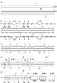
- a thin and large glass plate 1 is used, and the single glass plate 1 is separated into a plurality of high strength glasses 10, 10.
- the manufacturing method will be described in the order of steps.
- the characteristic part is shown enlarged from the other part, unlike the actual dimensional ratio.
- a thin and large glass plate 1 is prepared.
- the plate thickness T1 of the glass plate 1 is not particularly limited, but is preferably about 0.4 to 1.0 mm in consideration of a request for thinning and workability.
- the glass plate 1 can be used in a 500 mm square if the plate thickness T1 is 0.4 mm, for example, and a 1 mm square can be used if the plate thickness T is 0.7 mm.
- the size of the plate 1 is appropriately determined in relation to the plate thickness T1 in consideration of handleability.
- a reinforcing layer 2 is formed on the glass plate 1.
- an ion exchange method (a method of forming a compressive stress layer by immersing in an ion-containing aqueous solution) or an air cooling strengthening method (a method of forming a compressive stress layer by blowing air after heating to quench the layer) Method).
- an air cooling strengthening method (a method of forming a compressive stress layer by blowing air after heating to quench the layer) Method).
- damage such as cracks is less likely to occur and the strength is increased compared to ordinary glass materials.
- a protective film 3 is formed on the glass plate 1 on which the reinforcing layer 2 is formed.
- the protective film 3 is for protecting the glass plate 1 from corrosion due to an etching process, which will be described later, and is formed only in a region excluding the cut portion 4 (width of about 0.05 to 1.0 mm).
- a peripheral part 4a serving as an outline of a product and an opening 4b for avoiding a microphone and a home button in a touch panel for a smartphone or a tablet are set.
- a photoresist photosensitive resin
- a region other than the cut portion 4 is covered with a photomask 6 in which an exposure hole 5 is formed, and exposure is performed by irradiating UV light to print a pattern.
- the baked pattern is developed with an alkaline aqueous solution, and the protective film 3 may be patterned on the reinforcing layer 2.
- the protective film 3 is patterned on both the front and back surfaces of the glass plate 1, but may be patterned only on one side as shown in FIG. 2 (c '). In this case, the opposite surface is a solid protective film 3.
- the protective film 3 is peeled off after the etching process. For this reason, it replaces with the structure which forms a pattern with a photoresist, affixing the peelable protective sheet, the structure which cuts and patterns a protective sheet, and the patterned protective sheet cut beforehand is stuck
- a configuration, a configuration in which a resist pattern is printed, or the like may be employed.
- an etching process is performed on the cut portion 4 of the glass plate 1 that is not covered with the protective film 3.
- the etching process employs wet etching performed by infiltrating a chemical solution such as hydrofluoric acid.
- a chemical solution such as hydrofluoric acid.
- the recesses 7 are formed on both the front and back surfaces of the glass plate 1, but may be formed only on one of the surfaces as shown in FIG. That is, when the patterned protective film 3 is formed on one side as shown in FIG. 2 (c ′), the concave portion 7 is formed only on one side.
- the depth D of the recess 7 is preferably about 5 to 50 ⁇ m depending on the plate thickness T1 of the glass plate 1 and the reinforcing layer 2.
- the glass plate 1 in which the recesses 7 are formed is cut by machining.
- a cutting method first, the peripheral edge 4a is cut along the center of the concave portion 7 by using a diamond cutter, a cemented carbide wheel cutter, or a cutting machine 8 (8a) such as a laser or a diamond tool. And cut into a plurality of high-strength glasses 10, 10,.
- cutting machines 8 (8b) such as a diamond core drill and a circle cutter.
- the processing order of the peripheral portion 4a and the opening portion 4b may be either first, and the peripheral portion 4a can be cut into pieces after the opening of the opening portion 4b is formed.
- the high-strength glass 10 cut in this way is formed into a shape having a stepped portion 11 having a convex cross section on the peripheral end face 1a and the opening end face 1b of the glass plate 1, as shown in FIG. 2 (f).
- the glass strength is weakened.
- the width W is too short, the stepped portion is damaged at the time of cutting, and the strength cannot be ensured. .
- a finishing process for polishing the stepped portion 11 may be performed.
- this finishing treatment it is preferable that the end surface of the stepped portion 11 is formed into a curved shape by fixing the high-strength glass 10 and polishing while feeding the rotating grindstone 9 (9A) having a curved processing surface.
- the rotating grindstone 9 (9A) to be used preferably has a fine particle size of about # 800.
- the yarn chamfering rotary grindstone 9 (9B) or the straight rotating grindstone 9 (9C) may be used to process the yarn chamfer or straight. , Can be formed into any shape.
- a stepped portion 11 having a predetermined width is formed on the peripheral end face 1a and the open end face 1b of the glass plate 1.
- the stepped portion 11 has two side surfaces, an inner side surface 12 and an outer side surface 13.
- both side surfaces have different formation methods as described above, their surface states are different.
- the inner side surface 12 is formed by an etching process, and the glass plate 1 is a surface corroded with a chemical solution such as hydrofluoric acid. Therefore, there are no scratches such as microcracks that cause cracks. Does not occur.
- the outer surface 13 is formed by a cutting machine 8 such as a diamond cutter, and becomes a surface obtained by cutting the glass plate 1 by machining, so that fine scratches such as microcracks may occur. There is sex.
- the stress applied to the high-strength glass 10 acts on both surfaces of the glass plate 1 (the surface on which the reinforced layer 2 is formed) and is absorbed, the stress is applied to the inner surface 12 of the stepped portion 11 adjacent to this surface. If there are no cracks or the like, cracks starting from microcracks and the like do not occur. Further, even if microcracks or the like are present on the outer side surface 13 of the stepped portion 11, if the cracks or the like do not reach at least the inner side surface 12, the stress acting on both surfaces of the glass plate 1 is separated therefrom. It is considered that the outer side surface 13 does not concentrate on the microcracks or the like and does not adversely affect the strength.
- the high-strength glass 10 manufactured by the method of the present invention it is possible to reliably prevent breakage such as cracks due to microcracks and the like, and to secure strength against stress.
- the processing time for maintaining the strength of the high-strength glass 10 can be shortened. That is, in the conventional method, etching processing is performed on all cut surfaces of the tempered glass (four side surfaces excluding the front surface and the back surface of the glass plate 1). Since it only needs to be in the vicinity of 4, the processing area is much smaller than in the conventional method. Further, the outer surface 13 of the stepped portion 11 can be molded in a short time by cutting with a cutting machine 8 such as a diamond cutter.
- the processing time for maintaining the strength is greatly shortened, and the production efficiency can be improved.
- the outer surface 13 of the stepped portion 11 is machined into an arbitrary shape such as a curved shape in FIG. 3A, a thread chamfered shape in FIG. 3B, or a straight shape in FIG. 3C. Is possible.
- the glass plate 1 is etched and then cut into individual pieces.
- the glass plate 1 is cut and subjected to end face processing, and then the etching process is performed. May be adopted.
- the reinforcing layer 2 shown in FIG. 4 (b) is formed on both surfaces of the large glass plate 1 shown in FIG. 4 (a).
- an ion exchange method or an air cooling strengthening method can be employed in the same manner as described above.
- the reinforcing layer 2 is formed on both surfaces of the glass plate 1.
- the glass plate 1 on which the reinforcing layer 2 is formed is cut by machining.
- a cutting method first, the peripheral portion 4a is cut along the cutting portion 4a which is the outer shape of the product using a diamond cutter, a wheel cutter made of cemented carbide, or a cutting machine 8a such as a laser or a diamond tool. These are separated into a plurality of high-strength glasses 10, 10,.
- a hole is made in the glass plate 1 using cutting machines 8b, such as a diamond core drill and a circle cutter.
- cutting machines 8b such as a diamond core drill and a circle cutter.
- the processing order of the peripheral edge 4a and the opening 4b may be either, and the peripheral edge 4a can be cut into pieces after the opening of the opening 4b is made.
- a protective film 3 is formed in a region excluding the peripheral portion (width of about 50 to 500 ⁇ m) and the opening of the cut glass plate 1.
- the formation method is the same as the above-described method, after applying and drying a photoresist, covering with a photomask 6 in which the exposure holes 5 are formed, and exposing and developing to form a pattern and a photolithography technique or a protective sheet Adhesion or resist printing may be employed.
- This protective film 3 is also formed on both surfaces of the glass plate 1.
- a large glass plate (large plate) is used as the glass plate 1, but it is not necessary to use a large plate, and a small glass plate (small plate) can be used.
- the protective film 3 is formed in FIG. 4D after the large plate is separated into pieces, the protective film 3 may be formed at the time of the large plate shown in FIG. 4B. Further, in addition to the large sheet, the protective film 3 may be formed by attaching a protective sheet or pattern-printing a resist after separation.
- the cut end face may be subjected to a finishing process in which the end face is curved, chamfered or polished.
- an etching process is performed on the peripheral edge and the opening of the glass plate 1 not covered with the protective film 3.
- the etching process is also performed by wet etching in which a chemical solution such as hydrofluoric acid penetrates in the same manner as described above.
- a chemical solution such as hydrofluoric acid penetrates in the same manner as described above.
- the stepped portion 11 is formed by performing an etching process after the finishing process for polishing the end face.
- the end face is finally polished.
- a finishing process may be applied. In other words, either the finishing process or the etching process may be performed first.
- the high-strength glass (tempered glass) 10 manufactured by the above method also has a stepped portion 11 having a predetermined width on the peripheral end face 1a and the open end face 1b of the glass plate 1.
- the stepped portion 11 includes an inner surface 12 corroded by an etching process and an outer surface 13 cut by machining. Breakage such as cracks due to microcracks or the like can be reliably prevented, and strength against stress can be secured.
- the present invention is applied to the tempered glass in which the tempering layers 2 are provided on both surfaces of the glass plate 1.
- the present invention provides an effect of increasing the strength even when applied to the raw glass.
- the basic glass refers to glass that is not provided with a reinforcing layer.
- cutting portions 4 (4a, 4b) as shown in FIG. 5 (b) are formed on both surfaces of the glass plate 1 such as soda glass or borosilicate glass shown in FIG. 5 (a).
- a protective film 3 is formed in the excluded region.
- an etching process is performed on the cut portion 4 of the glass plate 1 that is not covered with the protective film 3 to form a recess 7 having a predetermined depth as shown in FIG. After the etching process is completed, the protective film 3 that is no longer necessary is removed by peeling off with strong alkali.
- the hole 4b is made in the opening part 4b of the glass plate 1 in which the recessed part 7 was formed in both surfaces with the cutting machine 8b, and the peripheral part 4a is cut
- a finishing process for polishing the stepped portion 11 may be performed.
- the high-strength glass (elementary glass) 10 manufactured in this way has a stepped portion 11 having a predetermined width on the peripheral end surface 1a and the opening end surface 1b of the glass plate 1, and therefore, for the reasons described above, microcracks, etc. It is possible to reliably prevent breakage such as cracks and to ensure strength against stress.
- the soda glass subjected to the tempering treatment of the end face convex finish according to the present invention has a strength of about 10% compared to the soda glass not subjected to the tempering treatment. It was found to improve 2 to 5 times.
- the present invention can obtain the effect of increasing the strength even when applied to laminated glass as well as raw glass.
- the laminated glass refers to a glass laminated together.
- As its form there are three possible forms: (1) those obtained by laminating raw glass, (2) those obtained by laminating tempered glass, and (3) those obtained by laminating raw glass and tempered glass. .
- the thickness T2 of the glass plate 1 is not particularly limited, but from a thin one of about 0.03 to 0.3 mm, to about 0.3 to 0.5 mm for glass for a mobile phone, and further to in-vehicle glass and crime prevention. If it is glass or the like, it can be widely used up to a thick type of millimeter unit exceeding 1.0 mm.
- the two glass plates 1 and 1 are bonded.
- a general adhesive, a thermosetting adhesive, or an intermediate film 14 such as a thermosetting film, a UV adhesive, or a UV resin sheet is sandwiched between the glass plates 1 and 1, and heat treatment is performed in an autoclave. Or by heating / pressurizing.
- the film thickness T3 of the intermediate film 14 to be used is preferably about 20 to 200 ⁇ m.
- the protective film 3 is formed on the both sides of the laminated glass in the region excluding the cut portions 4 (4a, 4b).
- the protective film 3 is removed (FIG. 4C)
- a hole is made in the opening 4b with a cutting machine 8b, and the peripheral edge 4a is cut. Cutting with the machine 8a (FIG. 4D).
- a finishing process for polishing the stepped portion 11 may be performed (FIG. 4E).
- the large glass plates are bonded to each other.
- individual glass plates may be bonded to each other. That is, the large glass plate 1 is cut as shown in FIG. 8 (a), and the intermediate film 14 is sandwiched between the small glass plates 1 and 1 separated as shown in FIG. 8 (b). To do.
- the step of forming the recess 7 described with reference to FIG. 7 can be omitted. Therefore, after the perforating process shown in FIG. 8C and the finishing process for polishing the end face shown in FIG. 8D are performed, the protective film 3 is formed and the etching process is performed, so that FIG. As shown, a stepped portion 11 having a convex cross section may be formed.
- the high-strength glass (laminated glass) 10 manufactured in this manner has a stepped portion 11 having a predetermined width on the peripheral end face 1a and the opening end face 1b of the glass plate 1, and therefore, for the reasons described above, microcracks, etc. It is possible to reliably prevent breakage such as cracks and to ensure strength against stress. Moreover, according to the high-strength glass 10 of this embodiment, since the intermediate film 14 is provided between the glass plates 1 and 1, it is excellent in impact resistance and even if the glass plate 1 is broken by any chance. Safe because no debris scatters.
- the high-strength glass according to the present invention can be used as a part of touch panel electronic devices such as smartphones, tablet terminals, car navigation devices and the like.
- touch panel electronic devices such as smartphones, tablet terminals, car navigation devices and the like.
- it can be used as a capacitive touch panel in which a transparent conductive film and an insulating film are laminated on one side of high-strength glass, or a cover glass having a decorative layer provided on the periphery of high-strength glass.
- this invention is applied to a laminated glass, it can also be used as a large glass such as an in-vehicle glass or a security glass.
Landscapes
- Chemical & Material Sciences (AREA)
- Engineering & Computer Science (AREA)
- Materials Engineering (AREA)
- Organic Chemistry (AREA)
- Life Sciences & Earth Sciences (AREA)
- Chemical Kinetics & Catalysis (AREA)
- General Chemical & Material Sciences (AREA)
- Geochemistry & Mineralogy (AREA)
- General Engineering & Computer Science (AREA)
- Theoretical Computer Science (AREA)
- Human Computer Interaction (AREA)
- Physics & Mathematics (AREA)
- General Physics & Mathematics (AREA)
- Re-Forming, After-Treatment, Cutting And Transporting Of Glass Products (AREA)
- Surface Treatment Of Glass (AREA)
- Devices For Indicating Variable Information By Combining Individual Elements (AREA)
- Micro-Organisms Or Cultivation Processes Thereof (AREA)
Priority Applications (2)
| Application Number | Priority Date | Filing Date | Title |
|---|---|---|---|
| CN201280062203.2A CN103987668A (zh) | 2011-12-16 | 2012-04-02 | 高强度玻璃、触摸面板、以及高强度玻璃的制造方法 |
| CA2859497A CA2859497A1 (en) | 2011-12-16 | 2012-04-02 | High-strength glass, touch panel, and method for manufacturing high-strength glass |
Applications Claiming Priority (2)
| Application Number | Priority Date | Filing Date | Title |
|---|---|---|---|
| JP2011-276084 | 2011-12-16 | ||
| JP2011276084A JP4932059B1 (ja) | 2011-12-16 | 2011-12-16 | 強化ガラス、タッチパネル、及び強化ガラスの製造方法 |
Publications (1)
| Publication Number | Publication Date |
|---|---|
| WO2013088755A1 true WO2013088755A1 (ja) | 2013-06-20 |
Family
ID=45877994
Family Applications (1)
| Application Number | Title | Priority Date | Filing Date |
|---|---|---|---|
| PCT/JP2012/058835 Ceased WO2013088755A1 (ja) | 2011-12-16 | 2012-04-02 | 高強度ガラス、タッチパネル、及び高強度ガラスの製造方法 |
Country Status (9)
| Country | Link |
|---|---|
| US (1) | US20130155004A1 (https=) |
| EP (1) | EP2604584B1 (https=) |
| JP (1) | JP4932059B1 (https=) |
| KR (1) | KR101225543B1 (https=) |
| CN (2) | CN103159411A (https=) |
| CA (2) | CA2770927C (https=) |
| ES (1) | ES2492541T3 (https=) |
| TW (1) | TW201235206A (https=) |
| WO (1) | WO2013088755A1 (https=) |
Cited By (2)
| Publication number | Priority date | Publication date | Assignee | Title |
|---|---|---|---|---|
| JP2014214077A (ja) * | 2013-04-30 | 2014-11-17 | 日本電気硝子株式会社 | 複合板の切断方法 |
| CN112975649A (zh) * | 2021-02-18 | 2021-06-18 | 雅安格纳斯光电科技有限公司 | 一种玻璃镜片磨边工艺 |
Families Citing this family (45)
| Publication number | Priority date | Publication date | Assignee | Title |
|---|---|---|---|---|
| JP5536534B2 (ja) * | 2010-05-17 | 2014-07-02 | 株式会社ディスコ | ガラス板の分割方法 |
| EP2645208A4 (en) * | 2010-11-25 | 2014-08-20 | Optsol Co Ltd | HARD GLASS PANEL FOR A TOUCH PANEL AND METHOD OF MANUFACTURING THEREOF |
| US10357850B2 (en) | 2012-09-24 | 2019-07-23 | Electro Scientific Industries, Inc. | Method and apparatus for machining a workpiece |
| US9828278B2 (en) | 2012-02-28 | 2017-11-28 | Electro Scientific Industries, Inc. | Method and apparatus for separation of strengthened glass and articles produced thereby |
| JP2015511571A (ja) | 2012-02-28 | 2015-04-20 | エレクトロ サイエンティフィック インダストリーズ インコーポレーテッド | 強化ガラスの分離のための方法及び装置並びにこれにより生成された製品 |
| WO2013130608A1 (en) * | 2012-02-29 | 2013-09-06 | Electro Scientific Industries, Inc. | Methods and apparatus for machining strengthened glass and articles produced thereby |
| US20130288010A1 (en) * | 2012-04-27 | 2013-10-31 | Ravindra Kumar Akarapu | Strengthened glass article having shaped edge and method of making |
| CN103677357B (zh) * | 2012-09-06 | 2016-12-28 | 宸鸿科技(厦门)有限公司 | 用于触控面板的盖板结构及其制造方法与触控面板 |
| CN102923961A (zh) * | 2012-09-17 | 2013-02-13 | 江西沃格光电科技有限公司 | 提高强化玻璃切割后抗压强度的方法 |
| US9946302B2 (en) * | 2012-09-19 | 2018-04-17 | Apple Inc. | Exposed glass article with inner recessed area for portable electronic device housing |
| JP6038573B2 (ja) * | 2012-09-27 | 2016-12-07 | 芝浦メカトロニクス株式会社 | ガラス基板加工装置及びガラス基板加工方法 |
| JP2014069995A (ja) * | 2012-09-28 | 2014-04-21 | Kiso Micro Kk | ガラス基板の製造方法 |
| JP2014084266A (ja) * | 2012-10-26 | 2014-05-12 | Dainippon Printing Co Ltd | パターン付きガラス基板の製造方法およびパターン付きマザーガラス基板の切断方法。 |
| CN103838443A (zh) * | 2012-11-26 | 2014-06-04 | 比亚迪股份有限公司 | 一种电容屏的制作方法 |
| CN102999240B (zh) * | 2012-12-15 | 2015-05-13 | 江西联创电子股份有限公司 | Ogs玻璃的外形加工方法 |
| CN103864311A (zh) * | 2012-12-18 | 2014-06-18 | 睿明科技股份有限公司 | 玻璃基板的成型方法 |
| JP2014125360A (ja) * | 2012-12-25 | 2014-07-07 | Nippon Electric Glass Co Ltd | 強化板ガラス及びその製造方法 |
| US9308616B2 (en) | 2013-01-21 | 2016-04-12 | Innovative Finishes LLC | Refurbished component, electronic device including the same, and method of refurbishing a component of an electronic device |
| KR102062148B1 (ko) * | 2013-03-27 | 2020-01-06 | 삼성디스플레이 주식회사 | 유기 발광 표시 장치 및 그 제조 방법 |
| US20150060401A1 (en) * | 2013-08-29 | 2015-03-05 | Corning Incorporated | Method of edge coating a batch of glass articles |
| CN103941906B (zh) | 2013-08-30 | 2018-01-26 | 上海天马微电子有限公司 | 一种单片式触控屏的制备方法 |
| CN103522031B (zh) * | 2013-09-30 | 2016-06-29 | 苏州德龙激光股份有限公司 | 强化玻璃打孔方法 |
| TW201519021A (zh) * | 2013-11-01 | 2015-05-16 | Ghitron Technology Co Ltd | 以單一貼膜完成單片玻璃觸控面板側邊蝕刻強化之製程 |
| CN104699292A (zh) * | 2013-12-06 | 2015-06-10 | 胜华科技股份有限公司 | 强化基底的方法以及触控装置的基底 |
| CN104777925A (zh) * | 2014-01-10 | 2015-07-15 | 群创光电股份有限公司 | 板材及其制备方法 |
| US9321677B2 (en) | 2014-01-29 | 2016-04-26 | Corning Incorporated | Bendable glass stack assemblies, articles and methods of making the same |
| KR20150112093A (ko) * | 2014-03-26 | 2015-10-07 | 삼성디스플레이 주식회사 | 터치 스크린 패널 및 이의 제조 방법 |
| US9776906B2 (en) | 2014-03-28 | 2017-10-03 | Electro Scientific Industries, Inc. | Laser machining strengthened glass |
| CN104191736B (zh) * | 2014-09-01 | 2016-09-07 | 胡久波 | 提升玻璃强度的玻璃结构及其制作方法 |
| CN104233298B (zh) * | 2014-09-12 | 2016-10-05 | 昆山科森科技股份有限公司 | 用于金属料带连续蚀刻加工的制造方法 |
| US20160147323A1 (en) * | 2014-11-21 | 2016-05-26 | Interface Optoelectronics Corporation | Touch control panel structure and method of manufacturing the same |
| KR102493138B1 (ko) * | 2015-03-25 | 2023-01-30 | 니폰 덴키 가라스 가부시키가이샤 | 강화 유리판의 제조 방법, 및 강화용 유리판의 제조 방법 |
| KR101819608B1 (ko) | 2015-07-31 | 2018-01-17 | 코닝정밀소재 주식회사 | 유리 접합체 커팅 방법 및 커팅 장치 |
| CN105205456A (zh) * | 2015-08-31 | 2015-12-30 | 上海箩箕技术有限公司 | 玻璃外盖板的制作方法 |
| CN105892750A (zh) * | 2016-04-20 | 2016-08-24 | 京东方科技集团股份有限公司 | 触控基板制造方法、触控基板和触控显示屏 |
| KR102446856B1 (ko) * | 2016-06-29 | 2022-09-23 | 삼성디스플레이 주식회사 | 커버 윈도우 및 그 제조 방법 |
| KR102607582B1 (ko) * | 2016-08-30 | 2023-11-30 | 삼성디스플레이 주식회사 | 커버 윈도우, 커버 윈도우를 포함하는 표시 장치 및 커버 윈도우의 제조 방법 |
| JP6749608B2 (ja) * | 2017-03-31 | 2020-09-02 | 株式会社Nsc | ガラス基板の製造方法 |
| JP6749609B2 (ja) * | 2017-04-28 | 2020-09-02 | 株式会社Nsc | ガラス基板の製造方法 |
| KR102780490B1 (ko) * | 2019-06-20 | 2025-03-14 | 코닝 인코포레이티드 | 유리 리본 제조 방법 및 장치 |
| CN112185256B (zh) * | 2020-09-30 | 2023-01-24 | 武汉天马微电子有限公司 | 可折叠显示装置及其制备方法 |
| KR20220072012A (ko) | 2020-11-23 | 2022-06-02 | 삼성디스플레이 주식회사 | 글라스 및 그 제조 방법 |
| CN113386445B (zh) * | 2021-06-16 | 2022-08-30 | 海南海玻工程玻璃有限公司 | 一种夹层玻璃的加工装置及方法 |
| KR102525405B1 (ko) * | 2021-10-20 | 2023-04-25 | 주식회사 도우인시스 | 레이저를 이용한 코팅막 제거와 유리 절단 및 후처리 방법 |
| JP2024124008A (ja) * | 2023-03-02 | 2024-09-12 | 日本電気硝子株式会社 | ガラス樹脂積層体の製造方法及びガラス樹脂積層体 |
Citations (3)
| Publication number | Priority date | Publication date | Assignee | Title |
|---|---|---|---|---|
| JP2011136855A (ja) * | 2009-12-28 | 2011-07-14 | Optrex Corp | ガラス基板の製造方法 |
| JP2011164508A (ja) * | 2010-02-15 | 2011-08-25 | Sony Corp | 電気的固体装置の製造方法および電気的固体装置 |
| JP2012031018A (ja) * | 2010-07-30 | 2012-02-16 | Asahi Glass Co Ltd | 強化ガラス基板及び強化ガラス基板の溝加工方法と強化ガラス基板の切断方法 |
Family Cites Families (12)
| Publication number | Priority date | Publication date | Assignee | Title |
|---|---|---|---|---|
| US4911743A (en) * | 1986-05-29 | 1990-03-27 | Hughes Aircraft Company | Glass structure strengthening by etching |
| JPH03232731A (ja) * | 1990-02-08 | 1991-10-16 | Hitachi Chem Co Ltd | 化学切削性感光性ガラス製品の分割法 |
| JP4532316B2 (ja) * | 2005-03-22 | 2010-08-25 | 日本板硝子株式会社 | タッチパネル |
| JP5085014B2 (ja) * | 2005-05-26 | 2012-11-28 | 株式会社ジャパンディスプレイイースト | 半導体装置の製造方法及び半導体装置 |
| JP5467490B2 (ja) * | 2007-08-03 | 2014-04-09 | 日本電気硝子株式会社 | 強化ガラス基板の製造方法及び強化ガラス基板 |
| JP2009208983A (ja) | 2008-03-03 | 2009-09-17 | Hoya Corp | ガラス基材及びその製造方法 |
| KR101040789B1 (ko) * | 2009-01-16 | 2011-06-13 | 삼성모바일디스플레이주식회사 | 터치 스크린 패널 및 그 제조방법 |
| TW201121911A (en) * | 2009-12-23 | 2011-07-01 | Wintek Corp | Method for strengthening glass and reinforced glass structure |
| TWI438162B (zh) * | 2010-01-27 | 2014-05-21 | Wintek Corp | 強化玻璃切割方法及強化玻璃切割預置結構 |
| US8974268B2 (en) * | 2010-06-25 | 2015-03-10 | Corning Incorporated | Method of preparing an edge-strengthened article |
| US20120052302A1 (en) * | 2010-08-24 | 2012-03-01 | Matusick Joseph M | Method of strengthening edge of glass article |
| TWI402228B (zh) * | 2010-09-15 | 2013-07-21 | Wintek Corp | 強化玻璃切割方法、強化玻璃薄膜製程、強化玻璃切割預置結構及強化玻璃切割件 |
-
2011
- 2011-12-16 JP JP2011276084A patent/JP4932059B1/ja active Active
-
2012
- 2012-03-14 CA CA2770927A patent/CA2770927C/en active Active
- 2012-03-16 CN CN2012100715946A patent/CN103159411A/zh active Pending
- 2012-03-16 KR KR1020120027251A patent/KR101225543B1/ko not_active Expired - Fee Related
- 2012-03-16 US US13/422,489 patent/US20130155004A1/en not_active Abandoned
- 2012-03-16 TW TW101109075A patent/TW201235206A/zh not_active IP Right Cessation
- 2012-03-16 EP EP12159793.4A patent/EP2604584B1/en not_active Not-in-force
- 2012-03-16 ES ES12159793.4T patent/ES2492541T3/es active Active
- 2012-04-02 CN CN201280062203.2A patent/CN103987668A/zh active Pending
- 2012-04-02 CA CA2859497A patent/CA2859497A1/en not_active Abandoned
- 2012-04-02 WO PCT/JP2012/058835 patent/WO2013088755A1/ja not_active Ceased
Patent Citations (3)
| Publication number | Priority date | Publication date | Assignee | Title |
|---|---|---|---|---|
| JP2011136855A (ja) * | 2009-12-28 | 2011-07-14 | Optrex Corp | ガラス基板の製造方法 |
| JP2011164508A (ja) * | 2010-02-15 | 2011-08-25 | Sony Corp | 電気的固体装置の製造方法および電気的固体装置 |
| JP2012031018A (ja) * | 2010-07-30 | 2012-02-16 | Asahi Glass Co Ltd | 強化ガラス基板及び強化ガラス基板の溝加工方法と強化ガラス基板の切断方法 |
Cited By (2)
| Publication number | Priority date | Publication date | Assignee | Title |
|---|---|---|---|---|
| JP2014214077A (ja) * | 2013-04-30 | 2014-11-17 | 日本電気硝子株式会社 | 複合板の切断方法 |
| CN112975649A (zh) * | 2021-02-18 | 2021-06-18 | 雅安格纳斯光电科技有限公司 | 一种玻璃镜片磨边工艺 |
Also Published As
| Publication number | Publication date |
|---|---|
| TW201235206A (en) | 2012-09-01 |
| CA2770927A1 (en) | 2012-08-15 |
| TWI375622B (https=) | 2012-11-01 |
| KR101225543B1 (ko) | 2013-01-23 |
| JP2013126923A (ja) | 2013-06-27 |
| CA2859497A1 (en) | 2013-06-20 |
| CN103987668A (zh) | 2014-08-13 |
| JP4932059B1 (ja) | 2012-05-16 |
| US20130155004A1 (en) | 2013-06-20 |
| ES2492541T3 (es) | 2014-09-09 |
| EP2604584B1 (en) | 2014-07-23 |
| CN103159411A (zh) | 2013-06-19 |
| CA2770927C (en) | 2012-11-27 |
| EP2604584A1 (en) | 2013-06-19 |
Similar Documents
| Publication | Publication Date | Title |
|---|---|---|
| WO2013088755A1 (ja) | 高強度ガラス、タッチパネル、及び高強度ガラスの製造方法 | |
| KR101570658B1 (ko) | 쉬트컷팅을 이용한 측면강화된 윈도우 글래스의 제조방법 | |
| KR101931322B1 (ko) | 쉬트 컷팅을 이용한 측면강화된 윈도우 글래스의 제조방법 | |
| KR101420263B1 (ko) | 글라스 가공 방법 | |
| TWI439432B (zh) | Separation and Separation Method of Bonded Glass Plate | |
| EP3418263B1 (en) | Singulation of ion-exchanged substrates | |
| JP2005219960A (ja) | ガラスの切断分離方法、フラットパネルディスプレイ用ガラス基板、フラットパネルディスプレイ | |
| CN114097016A (zh) | 玻璃基体、盖板玻璃、组装体、组装体的制造方法、车载显示装置以及车载显示装置的制造方法 | |
| WO2015105164A1 (ja) | 端面保護層付きガラス基板の製造方法および端面保護層付きガラス基板 | |
| JP6111240B2 (ja) | 電子機器用カバーガラスのガラス基板の製造方法 | |
| KR20170075908A (ko) | 박막유리 제조방법 | |
| JP2010005899A (ja) | 成形型 | |
| WO2020013984A1 (en) | Carriers for microelectronics fabrication | |
| TWI804634B (zh) | 液晶面板製造方法 | |
| WO2018216712A1 (ja) | 透明性薄膜付ガラスパネル製造方法、透明性薄膜付液晶パネル製造方法、ガラスパネル製造方法、および液晶パネル製造方法 | |
| CN105278712A (zh) | 覆盖板与其制造方法 | |
| KR20120033566A (ko) | 강화유리 가공 방법 | |
| TW201413520A (zh) | 高抗破壞強度的觸控面板模組的製作方法及其成品 | |
| JP5995097B2 (ja) | 複合板の切断方法 | |
| KR20190111252A (ko) | 굽힘 특성이 강화된 강화 글라스 제조방법 | |
| JP6749608B2 (ja) | ガラス基板の製造方法 | |
| JP2018197800A (ja) | ガラスパネル製造方法および液晶パネル製造方法 | |
| KR20180045119A (ko) | 전면패턴이 구현된 카메라 윈도우의 제조방법 및 그에 의해 제조된 전면패턴이 구현된 카메라 윈도우 | |
| JP7098889B2 (ja) | 荷電粒子線露光用マスクおよびその製造方法 | |
| TWM494962U (zh) | 覆蓋板 |
Legal Events
| Date | Code | Title | Description |
|---|---|---|---|
| 121 | Ep: the epo has been informed by wipo that ep was designated in this application |
Ref document number: 12858601 Country of ref document: EP Kind code of ref document: A1 |
|
| ENP | Entry into the national phase |
Ref document number: 2859497 Country of ref document: CA |
|
| NENP | Non-entry into the national phase |
Ref country code: DE |
|
| 122 | Ep: pct application non-entry in european phase |
Ref document number: 12858601 Country of ref document: EP Kind code of ref document: A1 |