WO2013088755A1 - 高強度ガラス、タッチパネル、及び高強度ガラスの製造方法 - Google Patents
高強度ガラス、タッチパネル、及び高強度ガラスの製造方法 Download PDFInfo
- Publication number
- WO2013088755A1 WO2013088755A1 PCT/JP2012/058835 JP2012058835W WO2013088755A1 WO 2013088755 A1 WO2013088755 A1 WO 2013088755A1 JP 2012058835 W JP2012058835 W JP 2012058835W WO 2013088755 A1 WO2013088755 A1 WO 2013088755A1
- Authority
- WO
- WIPO (PCT)
- Prior art keywords
- glass
- glass plate
- strength
- cut
- stepped portion
- Prior art date
Links
- 239000011521 glass Substances 0.000 title claims abstract description 197
- 238000004519 manufacturing process Methods 0.000 title claims abstract description 30
- 238000000034 method Methods 0.000 title claims description 79
- 238000005520 cutting process Methods 0.000 claims abstract description 43
- 238000005530 etching Methods 0.000 claims abstract description 43
- 230000001681 protective effect Effects 0.000 claims abstract description 42
- 230000002093 peripheral effect Effects 0.000 claims abstract description 33
- 238000003754 machining Methods 0.000 claims abstract description 22
- 239000005341 toughened glass Substances 0.000 claims description 26
- 230000003014 reinforcing effect Effects 0.000 claims description 15
- 239000005340 laminated glass Substances 0.000 claims description 13
- 238000005498 polishing Methods 0.000 claims description 9
- 230000007797 corrosion Effects 0.000 abstract description 4
- 238000005260 corrosion Methods 0.000 abstract description 4
- 238000005336 cracking Methods 0.000 abstract description 4
- 230000002787 reinforcement Effects 0.000 abstract 1
- 229910003460 diamond Inorganic materials 0.000 description 9
- 239000010432 diamond Substances 0.000 description 9
- 238000007730 finishing process Methods 0.000 description 9
- 239000000243 solution Substances 0.000 description 7
- 239000000126 substance Substances 0.000 description 7
- KRHYYFGTRYWZRS-UHFFFAOYSA-N Fluorane Chemical compound F KRHYYFGTRYWZRS-UHFFFAOYSA-N 0.000 description 6
- 239000000758 substrate Substances 0.000 description 6
- 230000000694 effects Effects 0.000 description 5
- 238000005496 tempering Methods 0.000 description 5
- 238000007796 conventional method Methods 0.000 description 4
- 239000006059 cover glass Substances 0.000 description 4
- 238000005728 strengthening Methods 0.000 description 4
- CDBYLPFSWZWCQE-UHFFFAOYSA-L Sodium Carbonate Chemical compound [Na+].[Na+].[O-]C([O-])=O CDBYLPFSWZWCQE-UHFFFAOYSA-L 0.000 description 3
- 239000000853 adhesive Substances 0.000 description 3
- 230000001070 adhesive effect Effects 0.000 description 3
- 230000015572 biosynthetic process Effects 0.000 description 3
- 239000012141 concentrate Substances 0.000 description 3
- 238000010438 heat treatment Methods 0.000 description 3
- 238000010030 laminating Methods 0.000 description 3
- 229920002120 photoresistant polymer Polymers 0.000 description 3
- 239000003513 alkali Substances 0.000 description 2
- 239000007864 aqueous solution Substances 0.000 description 2
- 238000005452 bending Methods 0.000 description 2
- 238000001816 cooling Methods 0.000 description 2
- 238000005342 ion exchange Methods 0.000 description 2
- 238000000206 photolithography Methods 0.000 description 2
- 239000011347 resin Substances 0.000 description 2
- 229920005989 resin Polymers 0.000 description 2
- 229920001187 thermosetting polymer Polymers 0.000 description 2
- 238000001039 wet etching Methods 0.000 description 2
- 230000002411 adverse Effects 0.000 description 1
- 238000007664 blowing Methods 0.000 description 1
- 239000005388 borosilicate glass Substances 0.000 description 1
- 239000003795 chemical substances by application Substances 0.000 description 1
- 239000006071 cream Substances 0.000 description 1
- 238000001035 drying Methods 0.000 description 1
- 239000010419 fine particle Substances 0.000 description 1
- 150000002500 ions Chemical class 0.000 description 1
- 230000001678 irradiating effect Effects 0.000 description 1
- 238000003698 laser cutting Methods 0.000 description 1
- 239000000463 material Substances 0.000 description 1
- 230000002265 prevention Effects 0.000 description 1
- 238000007639 printing Methods 0.000 description 1
- 238000010791 quenching Methods 0.000 description 1
- 238000010019 resist printing Methods 0.000 description 1
- 238000000926 separation method Methods 0.000 description 1
- 238000004904 shortening Methods 0.000 description 1
- 239000007787 solid Substances 0.000 description 1
Images


Classifications
-
- C—CHEMISTRY; METALLURGY
- C03—GLASS; MINERAL OR SLAG WOOL
- C03C—CHEMICAL COMPOSITION OF GLASSES, GLAZES OR VITREOUS ENAMELS; SURFACE TREATMENT OF GLASS; SURFACE TREATMENT OF FIBRES OR FILAMENTS MADE FROM GLASS, MINERALS OR SLAGS; JOINING GLASS TO GLASS OR OTHER MATERIALS
- C03C15/00—Surface treatment of glass, not in the form of fibres or filaments, by etching
-
- C—CHEMISTRY; METALLURGY
- C03—GLASS; MINERAL OR SLAG WOOL
- C03B—MANUFACTURE, SHAPING, OR SUPPLEMENTARY PROCESSES
- C03B33/00—Severing cooled glass
- C03B33/02—Cutting or splitting sheet glass or ribbons; Apparatus or machines therefor
- C03B33/023—Cutting or splitting sheet glass or ribbons; Apparatus or machines therefor the sheet or ribbon being in a horizontal position
-
- C—CHEMISTRY; METALLURGY
- C03—GLASS; MINERAL OR SLAG WOOL
- C03B—MANUFACTURE, SHAPING, OR SUPPLEMENTARY PROCESSES
- C03B33/00—Severing cooled glass
- C03B33/07—Cutting armoured, multi-layered, coated or laminated, glass products
-
- C—CHEMISTRY; METALLURGY
- C03—GLASS; MINERAL OR SLAG WOOL
- C03B—MANUFACTURE, SHAPING, OR SUPPLEMENTARY PROCESSES
- C03B33/00—Severing cooled glass
- C03B33/07—Cutting armoured, multi-layered, coated or laminated, glass products
- C03B33/074—Glass products comprising an outer layer or surface coating of non-glass material
-
- C—CHEMISTRY; METALLURGY
- C03—GLASS; MINERAL OR SLAG WOOL
- C03C—CHEMICAL COMPOSITION OF GLASSES, GLAZES OR VITREOUS ENAMELS; SURFACE TREATMENT OF GLASS; SURFACE TREATMENT OF FIBRES OR FILAMENTS MADE FROM GLASS, MINERALS OR SLAGS; JOINING GLASS TO GLASS OR OTHER MATERIALS
- C03C17/00—Surface treatment of glass, not in the form of fibres or filaments, by coating
- C03C17/001—General methods for coating; Devices therefor
- C03C17/002—General methods for coating; Devices therefor for flat glass, e.g. float glass
-
- G—PHYSICS
- G06—COMPUTING; CALCULATING OR COUNTING
- G06F—ELECTRIC DIGITAL DATA PROCESSING
- G06F3/00—Input arrangements for transferring data to be processed into a form capable of being handled by the computer; Output arrangements for transferring data from processing unit to output unit, e.g. interface arrangements
- G06F3/01—Input arrangements or combined input and output arrangements for interaction between user and computer
- G06F3/03—Arrangements for converting the position or the displacement of a member into a coded form
- G06F3/041—Digitisers, e.g. for touch screens or touch pads, characterised by the transducing means
-
- C—CHEMISTRY; METALLURGY
- C03—GLASS; MINERAL OR SLAG WOOL
- C03C—CHEMICAL COMPOSITION OF GLASSES, GLAZES OR VITREOUS ENAMELS; SURFACE TREATMENT OF GLASS; SURFACE TREATMENT OF FIBRES OR FILAMENTS MADE FROM GLASS, MINERALS OR SLAGS; JOINING GLASS TO GLASS OR OTHER MATERIALS
- C03C2218/00—Methods for coating glass
- C03C2218/30—Aspects of methods for coating glass not covered above
- C03C2218/34—Masking
-
- G—PHYSICS
- G06—COMPUTING; CALCULATING OR COUNTING
- G06F—ELECTRIC DIGITAL DATA PROCESSING
- G06F2203/00—Indexing scheme relating to G06F3/00 - G06F3/048
- G06F2203/041—Indexing scheme relating to G06F3/041 - G06F3/045
- G06F2203/04103—Manufacturing, i.e. details related to manufacturing processes specially suited for touch sensitive devices
-
- Y—GENERAL TAGGING OF NEW TECHNOLOGICAL DEVELOPMENTS; GENERAL TAGGING OF CROSS-SECTIONAL TECHNOLOGIES SPANNING OVER SEVERAL SECTIONS OF THE IPC; TECHNICAL SUBJECTS COVERED BY FORMER USPC CROSS-REFERENCE ART COLLECTIONS [XRACs] AND DIGESTS
- Y02—TECHNOLOGIES OR APPLICATIONS FOR MITIGATION OR ADAPTATION AGAINST CLIMATE CHANGE
- Y02P—CLIMATE CHANGE MITIGATION TECHNOLOGIES IN THE PRODUCTION OR PROCESSING OF GOODS
- Y02P40/00—Technologies relating to the processing of minerals
- Y02P40/50—Glass production, e.g. reusing waste heat during processing or shaping
- Y02P40/57—Improving the yield, e-g- reduction of reject rates
-
- Y—GENERAL TAGGING OF NEW TECHNOLOGICAL DEVELOPMENTS; GENERAL TAGGING OF CROSS-SECTIONAL TECHNOLOGIES SPANNING OVER SEVERAL SECTIONS OF THE IPC; TECHNICAL SUBJECTS COVERED BY FORMER USPC CROSS-REFERENCE ART COLLECTIONS [XRACs] AND DIGESTS
- Y10—TECHNICAL SUBJECTS COVERED BY FORMER USPC
- Y10T—TECHNICAL SUBJECTS COVERED BY FORMER US CLASSIFICATION
- Y10T428/00—Stock material or miscellaneous articles
- Y10T428/24—Structurally defined web or sheet [e.g., overall dimension, etc.]
- Y10T428/24479—Structurally defined web or sheet [e.g., overall dimension, etc.] including variation in thickness
- Y10T428/24488—Differential nonuniformity at margin
Definitions
- the present invention is a tempered glass, a glass plate, or a laminated glass, a high-strength glass capable of preventing damage such as micro cracks generated when cutting the glass plate and cracking due to chipping, and ensuring strength against stress.
- the present invention relates to a touch panel using high-strength glass and a method for producing high-strength glass.
- a touch panel is configured by bonding a cover glass and an electrostatic sensor.
- a cover glass As a feature of the cover glass, a cover that is as thin as possible and has high strength against stress is required.
- Tempered glass is generally known as such a high strength glass.
- Tempered glass is a glass plate with a compressive stress layer (strengthen layer) on the front and back and peripheral edge surfaces, strengthening it on six sides, thereby increasing strength compared to normal glass and preventing damage such as cracking. It is.
- a compressive stress layer stress layer
- cover glass in large quantities using this tempered glass, prepare a large glass plate with a reinforced layer, cut this glass plate with a wheel cutter, laser, etc., Manufactures multiple pieces of tempered glass.
- the tempered glass separated into pieces becomes two-sided tempering of the substrate after cutting, the strength becomes extremely weaker than that of six-sided tempering, and countless fine cracks (so-called Micro-cracks and chipping, hereinafter referred to as “micro-cracks, etc.”) occur. Therefore, if stress concentrates on the micro-cracks, it leads to breakage such as cracks, which causes a reduction in the strength of the tempered glass. Therefore, conventionally, in order to maintain the strength of the tempered glass, the cut surface of the tempered glass is subjected to an etching process with a chemical solution to corrode and remove microcracks and the like.
- Patent Document 1 a method of cutting a large glass substrate after etching is described as a method for preventing damage to the tempered glass due to stress.
- the edge of the substrate is polished to remove the protrusions remaining on the edge of the substrate, and further, the end surface of the substrate is subjected to an etching process. Since the etching process must be performed multiple times, the processing time becomes long and the production efficiency deteriorates.
- the present invention was made in order to solve the above-mentioned problems, and its purpose is to reliably prevent breakage such as cracks caused by microcracks generated when cutting a glass plate, and the like.
- the purpose is to improve the production efficiency by shortening the processing time for maintaining the strength of the glass plate.
- the high-strength glass of the present invention includes a tempered glass in which a tempered layer is provided on both surfaces of a glass plate, and a step having a convex cross section formed on a peripheral end face or an open end face of the tempered glass.
- the stepped portion includes an inner surface corroded by an etching process and an outer surface cut by machining.
- the high-strength glass of the present invention comprises a glass plate and a stepped portion having a convex cross section formed on the peripheral end surface or the opening end surface of the glass plate, and the stepped portion is corroded by an etching process. It is characterized by comprising an inner side surface and an outer side surface cut by machining.
- the high-strength glass of the present invention comprises a laminated glass obtained by bonding glass plates, and a stepped portion having a convex cross section formed on a peripheral edge surface or an opening end surface of the laminated glass, The inner surface is corroded by an etching process and the outer surface is cut by machining.
- the etching process refers to a process of corroding glass with an etching agent such as a chemical solution or cream.
- machining refers to a process of processing glass using a cutting tool, a machine tool, or the like, and examples of cutting include wheel cutting, laser cutting, dicing cutting, and the like.
- the touch panel provided with the electrically conductive film and the insulating film on the said glass plate can also be manufactured using the high intensity
- the first method for producing the high-strength glass of the present invention is a method for producing a plurality of pieces of high-strength glass separated from a large glass plate, Forming a protective film in a region excluding the cut portion of the glass plate, forming a recess formed by corroding the glass plate by etching treatment in the cut portion of the glass plate not covered with the protective film, and A step of cutting the glass plate on which the concave portion is formed along the concave portion by machining, and forming a stepped portion having a convex section on the peripheral edge surface or the opening end surface of the cut glass plate.
- the second method for producing the high-strength glass of the present invention is a method for producing a plurality of pieces of high-strength glass separated from a large glass plate, and the glass plate is cut by machining. Etching the glass plate at the step, forming the protective film in a region excluding the peripheral edge or opening of the cut glass plate, and the peripheral edge or opening of the glass plate not covered with the protective film Forming a stepped portion having a convex cross section corroded by the step.
- both surfaces of a glass plate A step of forming a reinforcing layer may be included.
- the method for producing high-strength glass of the present invention may include a step of polishing the cut end surface into a curved shape, a chamfered surface, or a straight surface before or after the step of forming the stepped portion. .
- a stepped portion having a convex cross section is formed on the peripheral end face or the opening end face of the glass plate, and the inner side surface formed by etching and the outer side surface cut by machining Two side surfaces having different surface states were provided.
- the stress on the high-strength glass is absorbed by acting on both sides of the glass plate, so that microcracks and the like are not generated on the inner side surface of the stepped portion adjacent to this surface. No cracking occurs.
- the high-strength glass manufactured by the method of the present invention there is an effect that it is possible to reliably prevent breakage such as cracks due to microcracks and the like and to secure strength against stress.
- the outer surface of the stepped portion is shortened by cutting with a cutting machine such as a diamond cutter. Can be molded in time.
- the processing time for maintaining the strength is greatly shortened, the production efficiency can be improved, and the end face of the stepped portion is processed into an arbitrary shape for machining. There is an effect that can be.
- a thin and large glass plate 1 is used, and the single glass plate 1 is separated into a plurality of high strength glasses 10, 10.
- the manufacturing method will be described in the order of steps.
- the characteristic part is shown enlarged from the other part, unlike the actual dimensional ratio.
- a thin and large glass plate 1 is prepared.
- the plate thickness T1 of the glass plate 1 is not particularly limited, but is preferably about 0.4 to 1.0 mm in consideration of a request for thinning and workability.
- the glass plate 1 can be used in a 500 mm square if the plate thickness T1 is 0.4 mm, for example, and a 1 mm square can be used if the plate thickness T is 0.7 mm.
- the size of the plate 1 is appropriately determined in relation to the plate thickness T1 in consideration of handleability.
- a reinforcing layer 2 is formed on the glass plate 1.
- an ion exchange method (a method of forming a compressive stress layer by immersing in an ion-containing aqueous solution) or an air cooling strengthening method (a method of forming a compressive stress layer by blowing air after heating to quench the layer) Method).
- an air cooling strengthening method (a method of forming a compressive stress layer by blowing air after heating to quench the layer) Method).
- damage such as cracks is less likely to occur and the strength is increased compared to ordinary glass materials.
- a protective film 3 is formed on the glass plate 1 on which the reinforcing layer 2 is formed.
- the protective film 3 is for protecting the glass plate 1 from corrosion due to an etching process, which will be described later, and is formed only in a region excluding the cut portion 4 (width of about 0.05 to 1.0 mm).
- a peripheral part 4a serving as an outline of a product and an opening 4b for avoiding a microphone and a home button in a touch panel for a smartphone or a tablet are set.
- a photoresist photosensitive resin
- a region other than the cut portion 4 is covered with a photomask 6 in which an exposure hole 5 is formed, and exposure is performed by irradiating UV light to print a pattern.
- the baked pattern is developed with an alkaline aqueous solution, and the protective film 3 may be patterned on the reinforcing layer 2.
- the protective film 3 is patterned on both the front and back surfaces of the glass plate 1, but may be patterned only on one side as shown in FIG. 2 (c '). In this case, the opposite surface is a solid protective film 3.
- the protective film 3 is peeled off after the etching process. For this reason, it replaces with the structure which forms a pattern with a photoresist, affixing the peelable protective sheet, the structure which cuts and patterns a protective sheet, and the patterned protective sheet cut beforehand is stuck
- a configuration, a configuration in which a resist pattern is printed, or the like may be employed.
- an etching process is performed on the cut portion 4 of the glass plate 1 that is not covered with the protective film 3.
- the etching process employs wet etching performed by infiltrating a chemical solution such as hydrofluoric acid.
- a chemical solution such as hydrofluoric acid.
- the recesses 7 are formed on both the front and back surfaces of the glass plate 1, but may be formed only on one of the surfaces as shown in FIG. That is, when the patterned protective film 3 is formed on one side as shown in FIG. 2 (c ′), the concave portion 7 is formed only on one side.
- the depth D of the recess 7 is preferably about 5 to 50 ⁇ m depending on the plate thickness T1 of the glass plate 1 and the reinforcing layer 2.
- the glass plate 1 in which the recesses 7 are formed is cut by machining.
- a cutting method first, the peripheral edge 4a is cut along the center of the concave portion 7 by using a diamond cutter, a cemented carbide wheel cutter, or a cutting machine 8 (8a) such as a laser or a diamond tool. And cut into a plurality of high-strength glasses 10, 10,.
- cutting machines 8 (8b) such as a diamond core drill and a circle cutter.
- the processing order of the peripheral portion 4a and the opening portion 4b may be either first, and the peripheral portion 4a can be cut into pieces after the opening of the opening portion 4b is formed.
- the high-strength glass 10 cut in this way is formed into a shape having a stepped portion 11 having a convex cross section on the peripheral end face 1a and the opening end face 1b of the glass plate 1, as shown in FIG. 2 (f).
- the glass strength is weakened.
- the width W is too short, the stepped portion is damaged at the time of cutting, and the strength cannot be ensured. .
- a finishing process for polishing the stepped portion 11 may be performed.
- this finishing treatment it is preferable that the end surface of the stepped portion 11 is formed into a curved shape by fixing the high-strength glass 10 and polishing while feeding the rotating grindstone 9 (9A) having a curved processing surface.
- the rotating grindstone 9 (9A) to be used preferably has a fine particle size of about # 800.
- the yarn chamfering rotary grindstone 9 (9B) or the straight rotating grindstone 9 (9C) may be used to process the yarn chamfer or straight. , Can be formed into any shape.
- a stepped portion 11 having a predetermined width is formed on the peripheral end face 1a and the open end face 1b of the glass plate 1.
- the stepped portion 11 has two side surfaces, an inner side surface 12 and an outer side surface 13.
- both side surfaces have different formation methods as described above, their surface states are different.
- the inner side surface 12 is formed by an etching process, and the glass plate 1 is a surface corroded with a chemical solution such as hydrofluoric acid. Therefore, there are no scratches such as microcracks that cause cracks. Does not occur.
- the outer surface 13 is formed by a cutting machine 8 such as a diamond cutter, and becomes a surface obtained by cutting the glass plate 1 by machining, so that fine scratches such as microcracks may occur. There is sex.
- the stress applied to the high-strength glass 10 acts on both surfaces of the glass plate 1 (the surface on which the reinforced layer 2 is formed) and is absorbed, the stress is applied to the inner surface 12 of the stepped portion 11 adjacent to this surface. If there are no cracks or the like, cracks starting from microcracks and the like do not occur. Further, even if microcracks or the like are present on the outer side surface 13 of the stepped portion 11, if the cracks or the like do not reach at least the inner side surface 12, the stress acting on both surfaces of the glass plate 1 is separated therefrom. It is considered that the outer side surface 13 does not concentrate on the microcracks or the like and does not adversely affect the strength.
- the high-strength glass 10 manufactured by the method of the present invention it is possible to reliably prevent breakage such as cracks due to microcracks and the like, and to secure strength against stress.
- the processing time for maintaining the strength of the high-strength glass 10 can be shortened. That is, in the conventional method, etching processing is performed on all cut surfaces of the tempered glass (four side surfaces excluding the front surface and the back surface of the glass plate 1). Since it only needs to be in the vicinity of 4, the processing area is much smaller than in the conventional method. Further, the outer surface 13 of the stepped portion 11 can be molded in a short time by cutting with a cutting machine 8 such as a diamond cutter.
- the processing time for maintaining the strength is greatly shortened, and the production efficiency can be improved.
- the outer surface 13 of the stepped portion 11 is machined into an arbitrary shape such as a curved shape in FIG. 3A, a thread chamfered shape in FIG. 3B, or a straight shape in FIG. 3C. Is possible.
- the glass plate 1 is etched and then cut into individual pieces.
- the glass plate 1 is cut and subjected to end face processing, and then the etching process is performed. May be adopted.
- the reinforcing layer 2 shown in FIG. 4 (b) is formed on both surfaces of the large glass plate 1 shown in FIG. 4 (a).
- an ion exchange method or an air cooling strengthening method can be employed in the same manner as described above.
- the reinforcing layer 2 is formed on both surfaces of the glass plate 1.
- the glass plate 1 on which the reinforcing layer 2 is formed is cut by machining.
- a cutting method first, the peripheral portion 4a is cut along the cutting portion 4a which is the outer shape of the product using a diamond cutter, a wheel cutter made of cemented carbide, or a cutting machine 8a such as a laser or a diamond tool. These are separated into a plurality of high-strength glasses 10, 10,.
- a hole is made in the glass plate 1 using cutting machines 8b, such as a diamond core drill and a circle cutter.
- cutting machines 8b such as a diamond core drill and a circle cutter.
- the processing order of the peripheral edge 4a and the opening 4b may be either, and the peripheral edge 4a can be cut into pieces after the opening of the opening 4b is made.
- a protective film 3 is formed in a region excluding the peripheral portion (width of about 50 to 500 ⁇ m) and the opening of the cut glass plate 1.
- the formation method is the same as the above-described method, after applying and drying a photoresist, covering with a photomask 6 in which the exposure holes 5 are formed, and exposing and developing to form a pattern and a photolithography technique or a protective sheet Adhesion or resist printing may be employed.
- This protective film 3 is also formed on both surfaces of the glass plate 1.
- a large glass plate (large plate) is used as the glass plate 1, but it is not necessary to use a large plate, and a small glass plate (small plate) can be used.
- the protective film 3 is formed in FIG. 4D after the large plate is separated into pieces, the protective film 3 may be formed at the time of the large plate shown in FIG. 4B. Further, in addition to the large sheet, the protective film 3 may be formed by attaching a protective sheet or pattern-printing a resist after separation.
- the cut end face may be subjected to a finishing process in which the end face is curved, chamfered or polished.
- an etching process is performed on the peripheral edge and the opening of the glass plate 1 not covered with the protective film 3.
- the etching process is also performed by wet etching in which a chemical solution such as hydrofluoric acid penetrates in the same manner as described above.
- a chemical solution such as hydrofluoric acid penetrates in the same manner as described above.
- the stepped portion 11 is formed by performing an etching process after the finishing process for polishing the end face.
- the end face is finally polished.
- a finishing process may be applied. In other words, either the finishing process or the etching process may be performed first.
- the high-strength glass (tempered glass) 10 manufactured by the above method also has a stepped portion 11 having a predetermined width on the peripheral end face 1a and the open end face 1b of the glass plate 1.
- the stepped portion 11 includes an inner surface 12 corroded by an etching process and an outer surface 13 cut by machining. Breakage such as cracks due to microcracks or the like can be reliably prevented, and strength against stress can be secured.
- the present invention is applied to the tempered glass in which the tempering layers 2 are provided on both surfaces of the glass plate 1.
- the present invention provides an effect of increasing the strength even when applied to the raw glass.
- the basic glass refers to glass that is not provided with a reinforcing layer.
- cutting portions 4 (4a, 4b) as shown in FIG. 5 (b) are formed on both surfaces of the glass plate 1 such as soda glass or borosilicate glass shown in FIG. 5 (a).
- a protective film 3 is formed in the excluded region.
- an etching process is performed on the cut portion 4 of the glass plate 1 that is not covered with the protective film 3 to form a recess 7 having a predetermined depth as shown in FIG. After the etching process is completed, the protective film 3 that is no longer necessary is removed by peeling off with strong alkali.
- the hole 4b is made in the opening part 4b of the glass plate 1 in which the recessed part 7 was formed in both surfaces with the cutting machine 8b, and the peripheral part 4a is cut
- a finishing process for polishing the stepped portion 11 may be performed.
- the high-strength glass (elementary glass) 10 manufactured in this way has a stepped portion 11 having a predetermined width on the peripheral end surface 1a and the opening end surface 1b of the glass plate 1, and therefore, for the reasons described above, microcracks, etc. It is possible to reliably prevent breakage such as cracks and to ensure strength against stress.
- the soda glass subjected to the tempering treatment of the end face convex finish according to the present invention has a strength of about 10% compared to the soda glass not subjected to the tempering treatment. It was found to improve 2 to 5 times.
- the present invention can obtain the effect of increasing the strength even when applied to laminated glass as well as raw glass.
- the laminated glass refers to a glass laminated together.
- As its form there are three possible forms: (1) those obtained by laminating raw glass, (2) those obtained by laminating tempered glass, and (3) those obtained by laminating raw glass and tempered glass. .
- the thickness T2 of the glass plate 1 is not particularly limited, but from a thin one of about 0.03 to 0.3 mm, to about 0.3 to 0.5 mm for glass for a mobile phone, and further to in-vehicle glass and crime prevention. If it is glass or the like, it can be widely used up to a thick type of millimeter unit exceeding 1.0 mm.
- the two glass plates 1 and 1 are bonded.
- a general adhesive, a thermosetting adhesive, or an intermediate film 14 such as a thermosetting film, a UV adhesive, or a UV resin sheet is sandwiched between the glass plates 1 and 1, and heat treatment is performed in an autoclave. Or by heating / pressurizing.
- the film thickness T3 of the intermediate film 14 to be used is preferably about 20 to 200 ⁇ m.
- the protective film 3 is formed on the both sides of the laminated glass in the region excluding the cut portions 4 (4a, 4b).
- the protective film 3 is removed (FIG. 4C)
- a hole is made in the opening 4b with a cutting machine 8b, and the peripheral edge 4a is cut. Cutting with the machine 8a (FIG. 4D).
- a finishing process for polishing the stepped portion 11 may be performed (FIG. 4E).
- the large glass plates are bonded to each other.
- individual glass plates may be bonded to each other. That is, the large glass plate 1 is cut as shown in FIG. 8 (a), and the intermediate film 14 is sandwiched between the small glass plates 1 and 1 separated as shown in FIG. 8 (b). To do.
- the step of forming the recess 7 described with reference to FIG. 7 can be omitted. Therefore, after the perforating process shown in FIG. 8C and the finishing process for polishing the end face shown in FIG. 8D are performed, the protective film 3 is formed and the etching process is performed, so that FIG. As shown, a stepped portion 11 having a convex cross section may be formed.
- the high-strength glass (laminated glass) 10 manufactured in this manner has a stepped portion 11 having a predetermined width on the peripheral end face 1a and the opening end face 1b of the glass plate 1, and therefore, for the reasons described above, microcracks, etc. It is possible to reliably prevent breakage such as cracks and to ensure strength against stress. Moreover, according to the high-strength glass 10 of this embodiment, since the intermediate film 14 is provided between the glass plates 1 and 1, it is excellent in impact resistance and even if the glass plate 1 is broken by any chance. Safe because no debris scatters.
- the high-strength glass according to the present invention can be used as a part of touch panel electronic devices such as smartphones, tablet terminals, car navigation devices and the like.
- touch panel electronic devices such as smartphones, tablet terminals, car navigation devices and the like.
- it can be used as a capacitive touch panel in which a transparent conductive film and an insulating film are laminated on one side of high-strength glass, or a cover glass having a decorative layer provided on the periphery of high-strength glass.
- this invention is applied to a laminated glass, it can also be used as a large glass such as an in-vehicle glass or a security glass.
Landscapes
- Chemical & Material Sciences (AREA)
- Engineering & Computer Science (AREA)
- Materials Engineering (AREA)
- Organic Chemistry (AREA)
- Life Sciences & Earth Sciences (AREA)
- Chemical Kinetics & Catalysis (AREA)
- General Chemical & Material Sciences (AREA)
- Geochemistry & Mineralogy (AREA)
- General Engineering & Computer Science (AREA)
- Theoretical Computer Science (AREA)
- Human Computer Interaction (AREA)
- Physics & Mathematics (AREA)
- General Physics & Mathematics (AREA)
- Re-Forming, After-Treatment, Cutting And Transporting Of Glass Products (AREA)
- Surface Treatment Of Glass (AREA)
- Devices For Indicating Variable Information By Combining Individual Elements (AREA)
- Micro-Organisms Or Cultivation Processes Thereof (AREA)
Abstract
【課題】マイクロクラック等によるひび割れ等の破損を防ぐとともに、強度を維持するための処理時間を短縮化して生産効率を向上させることができ、しかも端面を任意の形状に成形できる高強度ガラスを提供する。 【解決手段】ガラス板1の両面に強化層2を形成し、切断部4を除く領域に保護膜3を形成する。次に、保護膜3で覆われていないガラス板1の切断部4にエッチング処理で腐食させた凹部7を形成する。そして、開口部4bに切断機8bで孔を開け、周縁部4aを切断機8aで切断して個片化された高強度ガラス10とし、ガラス板1の周縁端面1aと開口端面1bにエッチング処理で腐食させた内側面12と機械加工で切断された外側面13とからなる断面凸型の段付部11を形成する。なお、段付部11の端面は機械加工のため任意の形状に加工することが可能である。
Description
本発明は、強化ガラス、ガラス板、あるいは合わせガラスにおいて、ガラス板を切断する際に発生するマイクロクラックやチッピングによるひび割れ等の破損を防ぎ、応力に対する強度を確保できるようにした高強度ガラス、この高強度ガラスを用いたタッチパネル、及び高強度ガラスの製造方法に関する。
近年、例えばスマートフォン、タブレット型端末、カーナビゲーション装置等の電子機器において、タッチパネルを搭載した製品が多く市販されている。通常、タッチパネルはカバーガラスと静電センサーを貼り合わせることにより構成されているが、このカバーガラスの特徴として、できる限り薄型で、しかも応力に対する強度の高いものが求められている。
このような強度の高いガラスとして、一般に強化ガラスが知られている。強化ガラスとは、ガラス板の表裏面と周縁端面に圧縮応力層(強化層)を設けて6面強化し、これにより通常のガラスに比べて強度を高め、ひび割れ等の破損が起こりにくくしたものである。そして、この強化ガラスを利用してカバーガラス等の部品を大量に製造する場合には、強化層を設けた大型のガラス板を用意し、このガラス板をホイールカッターやレーザー等で切断して、複数枚の個片化された強化ガラスを製造している。
ところで、前記の方法によると、個片化された強化ガラスは切断後基板の上下の2面強化となり、6面強化と比べ強度が極端に弱くなり、また切断面に無数の細かな割れ目(いわゆるマイクロクラックやチッピング、以下「マイクロクラック等」という。)が発生するため、このマイクロクラック等に応力が集中するとひび割れ等の破損に繋がり、強化ガラスの強度を低下させる要因になっていた。そこで、従来は強化ガラスの強度を維持するために、強化ガラスの切断面に薬液によるエッチング処理を施し、マイクロクラック等を腐食させて取り除く作業を行っていた。
ところが、このエッチング処理は、個片化された強化ガラスの切断面(ガラス板の表面と裏面を除く側面4面)すべてに対して極度のエッチング処理を行わなければならず、また、使用する薬液の濃度を低くしているため、エッチング処理が完了してマイクロクラック等を取り除くまでに非常に長い時間を要している。さらに、処理時間を短縮するために薬液の濃度を高くすることも考えられるが、この場合、危険を伴う上に、腐食反応が強く起こり、エッチング処理を施した切断面に大きな凹凸が発生してしまう。このように、従来の強化ガラスの製造方法によると、ガラス板を切断した後、強化ガラスの強度を維持するための処理に長い時間が掛かり、生産効率が大きく低下するという問題があった。
なお、下記の特許文献1には、強化ガラスの応力による破損を防ぐ方法として、大型ガラス基板をエッチング処理した後に切断する方法が記載されている。しかし、この方法によると、大型ガラス基板を切断した後、基板の端部を研磨して基板の端部に残った突部を除去し、さらに基板の端面にエッチング処理を施すものであり、除去工程や複数回にわたるエッチング処理を行わなければならないため、やはり処理時間が長くなり、生産効率が悪くなってしまう。
本発明は、前記のような問題を解決するためになされたものであり、その目的とするところは、ガラス板を切断する際に発生するマイクロクラック等によるひび割れ等の破損を確実に防ぐとともに、ガラス板の強度を維持するための処理時間を短縮化して生産効率を向上させることにある。
前記の目的を達成するために、本発明の高強度ガラスは、ガラス板の両面に強化層が設けられた強化ガラスと、前記強化ガラスの周縁端面又は開口端面に形成された断面凸型の段付部とを具備し、前記段付部は、エッチング処理により腐食させた内側面と、機械加工により切断された外側面とを備えて構成されていることを特徴とする。
また、本発明の高強度ガラスは、ガラス板と、前記ガラス板の周縁端面又は開口端面に形成された断面凸型の段付部とを具備し、前記段付部は、エッチング処理により腐食させた内側面と、機械加工により切断された外側面とを備えて構成されていることを特徴とする。
また、本発明の高強度ガラスは、ガラス板同士を接着した合わせガラスと、前記合わせガラスの周縁端面又は開口端面に形成された断面凸型の段付部とを具備し、前記段付部は、エッチング処理により腐食させた内側面と、機械加工により切断された外側面とを備えて構成されていることを特徴とする。
ここで、エッチング処理とは、薬液やクリーム等のエッチング剤を用いてガラスを腐食させる処理をいう。また、機械加工とは、切削工具や工作機械等を用いてガラスを加工する処理をいい、切断加工として、例えばホイールカット、レーザーカット、ダイシングカット等の方法が挙げられる。
本発明の高強度ガラスにおいて、前記段付部の外側面は湾曲状、糸面取り、あるいはストレートに形成されている構造を採用することができる。また、本発明の高強度ガラスを用いて、前記ガラス板上に導電膜及び絶縁膜が設けられたタッチパネルを製造することもできる。
また、前記の目的を達成するために、本発明の高強度ガラスを製造する第1の方法は、大型のガラス板から個片化された複数枚の高強度ガラスを製造する方法であって、前記ガラス板の切断部を除く領域に保護膜を形成する工程と、前記保護膜で覆われていないガラス板の切断部に、ガラス板をエッチング処理により腐食させた凹部を形成する工程と、前記凹部が形成されたガラス板を機械加工により凹部に沿って切断し、切断されたガラス板の周縁端面又は開口端面に断面凸型の段付部を形成する工程とを有することを特徴とする。
また、本発明の高強度ガラスを製造する第2の方法は、大型のガラス板から個片化された複数枚の高強度ガラスを製造する方法であって、前記ガラス板を機械加工により切断する工程と、前記切断されたガラス板の周縁部又は開口部を除く領域に保護膜を形成する工程と、前記保護膜で覆われていないガラス板の周縁部又は開口部に、ガラス板をエッチング処理により腐食させた断面凸型の段付部を形成する工程とを有することを特徴とする。
なお、本発明の高強度ガラスの製造方法において、前記第1の方法における保護膜を形成する工程の前に、又は前記第2の方法における機械加工により切断する工程の前に、ガラス板の両面に強化層を形成する工程を有していても良い。また、前記第1の方法における保護膜を形成する工程の前に、又は前記第2の方法における機械加工により切断する工程の前もしくは後に、ガラス板同士を接着する工程を有していても良い。さらに、本発明の高強度ガラスの製造方法において、前記段付部を形成する工程の前又は後に、切断された端面を湾曲状、糸面取り、あるいはストレートに研磨する工程を有していても良い。
本発明によれば、切断後の高強度ガラスにおいて、ガラス板の周縁端面又は開口端面に断面凸型の段付部を形成し、エッチング処理で形成した内側面と機械加工で切断した外側面という表面状態の異なる2つの側面を設けるようにした。これにより、高強度ガラスに対する応力はガラス板の両面に作用して吸収され、この面と隣接する段付部の内側面にはマイクロクラック等が発生しないようにしたので、マイクロクラック等を起点とするひび割れが生じない。また、段付部の外側面に切断時のマイクロクラック等が発生していたとしても、ガラス板の両面に作用する応力は、そこから離れた外側面のマイクロクラック等に集中することはないため、強度に対する影響を及ぼさないと考えられる。
したがって、本発明方法で製造された高強度ガラスによれば、マイクロクラック等によるひび割れ等の破損を確実に防ぎ、応力に対する強度を確保することができるという効果がある。
また、従来方法では、強化ガラスの切断面すべてに対してエッチング処理を行っていたが、本発明方法の場合には、段付部の外側面はダイヤモンドカッター等の切断機で切断することにより短時間で成形することができる。
したがって、ガラス板を切断した後、強度を維持するための処理時間が大幅に短縮化され、生産効率を向上させることができ、しかも段付部の端面は機械加工のため任意の形状に加工することができるという効果がある。
以下、本発明を実施するための形態について、図面を参照しながら説明する。
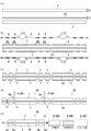
図1に示すように、本発明においては、薄型でかつ大型のガラス板1を使用し、この1枚のガラス板1を個片化して複数枚の高強度ガラス10,10,…が製造される。以下その製造方法を工程順に従って説明する。なお、以下の説明で参照する図面においては、構造を分かりやすくするため、実際の寸法比率とは異なり特徴的な部分を他の部分よりも拡大して表してある。
図2(a)に示すように、まず薄型でかつ大型のガラス板1を用意する。ガラス板1の板厚T1は特に限定されないが、薄型化の要請や加工性等を考慮すると0.4~1.0mm程度が好適である。また、ガラス板1のサイズは、例えば板厚T1が0.4mmであれば500mm角、板厚Tが0.7mmであれば1m角のものを使用することが可能であり、加工前のガラス板1のサイズは、取扱い性を考慮して板厚T1との関係で適宜決定される。
次に、図2(b)に示すように、ガラス板1に強化層2を形成する。強化層2の形成方法としては、イオン交換法(イオン含有水溶液に浸漬して圧縮応力層を形成する方法)や、風冷強化法(加熱後に空気を吹き付けて急冷することにより圧縮応力層を形成する方法)を採用することができる。本実施形態では、ガラス板1の表面と裏面の両面に強化層2を形成することにより、通常のガラス材に比べてひび割れ等の破損が起こりにくく、その強度が高められている。
続いて、図2(c)に示すように、強化層2が形成されたガラス板1に保護膜3を形成する。保護膜3は、後述のエッチング処理による腐食からガラス板1を保護するためのもので、切断部4(幅おおよそ0.05~1.0mm程度)を除く領域に限定して形成される。本実施形態では、切断部4として、製品の輪郭となる周縁部4aと、スマートフォンやタブレット用のタッチパネルにおいてマイクやホームボタンを避けるための開口部4bが設定されている。
保護膜3の形成方法としては、一般的なフォトリソグラフィ技術と同様に、まず強化層2の表面にフォトレジスト(感光性樹脂)を均一に塗布して乾燥させる。その後、切断部4を除く領域に露光孔5が形成されたフォトマスク6を被せ、UV光を照射することにより露光してパターンを焼き付ける。そして、焼き付けたパターンをアルカリ水溶液で現像し、強化層2の上に保護膜3をパターン形成すれば良い。保護膜3はガラス板1の表面と裏面の両面にパターン形成されているが、図2(c′)のように片面だけにパターン形成されていても良い。この場合、反対面はベタ塗りした保護膜3とする。
なお、保護膜3はエッチング処理後に剥離する。このため、フォトレジストでパターン形成する構成に代えて、剥離可能な保護シートを貼付し、保護シートをカットしてパターン化する構成や、予めカットしておいたパターン化された保護シートを貼付する構成や、レジストをパターン印刷する構成等を採用しても良い。
次に、保護膜3で覆われていないガラス板1の切断部4にエッチング処理を施す。エッチング処理は、本実施形態ではフッ酸等の薬液を浸透させて行うウエットエッチングを採用した。これにより切断部4に位置する強化層2とガラス板1が腐食され、図2(d)に示すような所定深さの凹部7が形成される。そして、エッチング処理が完了した後、不要になった保護膜3を強アルカリで剥離して取り除く。
ここで、凹部7は、ガラス板1の表面と裏面の両面に形成されているが、図2(d′)のようにいずれか一方の面だけに形成されていても良い。すなわち、図2(c′)のようにパターン化された保護膜3を片面に形成した場合には、その片面だけに凹部7を形成するようにする。なお、凹部7の深さDは、ガラス板1の板厚T1や強化層2に応じて、5~50μm程度にするのが好ましい。
続いて、図2(e)に示すように、凹部7が形成されたガラス板1を機械加工により切断する。切断方法としては、まず周縁部4aについて、ダイヤモンドカッター、超硬合金製のホイールカッター、あるいはレーザーやダイヤモンドツール等の切断機8(8a)を使用して、ガラス板1を凹部7の中心に沿って切断し、複数枚の高強度ガラス10,10,…に個片化する。次に開口部4bについて、ダイヤモンドコアドリルやサークルカッター等の切断機8(8b)を使用して、ガラス板1の凹部7に孔を開ける。ここで、周縁部4aと開口部4bの加工順序はどちらが先でも良く、開口部4bの孔を開けた後に周縁部4aを切断して個片化することもできる。こうして切断された高強度ガラス10は、図2(f)に示すように、ガラス板1の周縁端面1aと開口端面1bに断面凸型の段付部11を有する形状に成形される。
なお、段付部11の幅Wは、あまり長いとガラス強度が弱くなり、逆に短すぎると切断時に段差部分を傷つけてしまい強度を確保できないため、好ましくは50~500μm程度とするのが良い。
最後に、段付部11を研磨する仕上げ処理を施しても良い。この仕上げ処理は、高強度ガラス10を固定し、加工面が湾曲した回転砥石9(9A)を送り込みながら研磨することにより、段付部11の端面を湾曲状に成形するのが好ましい。
なお、使用する回転砥石9(9A)は、#800程度の細かい粒度のものが好適である。また、湾曲用の回転砥石9(9A)に代えて、糸面取り用の回転砥石9(9B)やストレート用の回転砥石9(9C)を使用して、糸面取りやストレートに加工しても良く、任意の形状に成形することができる。
以上のようにして製造された高強度ガラス(強化ガラス)10は、ガラス板1の周縁端面1aと開口端面1bに所定幅の段付部11が形成されている。この段付部11は、図3に示すように、内側面12と外側面13の2つの側面を有しているが、両側面は前記のとおり形成方法が異なることから、その表面状態が相違したものとなる。すなわち、内側面12はエッチング処理により形成されたものであり、ガラス板1をフッ酸等の薬液で腐食させた表面となるため、マイクロクラック等のような、ひび割れ等の原因となる傷は一切発生しない。これに対して、外側面13はダイヤモンドカッター等の切断機8により形成されたものであり、ガラス板1を機械加工で切断した表面となるため、マイクロクラック等の細かい傷が発生している可能性がある。
しかし、高強度ガラス10に対する応力は、ガラス板1の両面(強化層2が形成されている面)に作用して吸収されるため、この面と隣接する段付部11の内側面12にマイクロクラック等が存在しなければマイクロクラック等を起点とするひび割れは生じない。また、段付部11の外側面13にマイクロクラック等が存在していても、そのクラック等が少なくとも内側面12にまで及んでいなければ、ガラス板1の両面に作用した応力がそこから離れた外側面13のマイクロクラック等に集中することはなく、強度に対して悪影響を及ぼすことはないものと考えられる。
したがって、本発明方法で製造された高強度ガラス10によれば、マイクロクラック等によるひび割れ等の破損を確実に防ぎ、応力に対する強度を確保することができる。
また、本発明方法によれば、ガラス板1を切断した後、高強度ガラス10の強度を維持するための処理時間を短縮化できるという効果もある。すなわち、従来方法では、強化ガラスの切断面(ガラス板1の表面と裏面を除く側面4面)すべてに対してエッチング処理を行っていたが、本発明方法の場合には、エッチング処理を切断部4付近に行えば良いため、従来方法に比べて処理面積が圧倒的に少なくて済む。また、段付部11の外側面13はダイヤモンドカッター等の切断機8で切断することにより短時間で成形することができる。
したがって、強度を維持するための処理時間が大幅に短縮化され、生産効率を向上させることができる。しかも、段付部11の外側面13は機械加工のため、図3(a)の湾曲形状、図3(b)の糸面取り形状、図3(c)のストレート形状などの任意の形状に加工することが可能である。
なお、前述した製造方法では、ガラス板1にエッチング処理を施した後に切断して個片化したが、これに代えて、ガラス板1を切断して端面加工を施した後にエッチング処理を施す方法を採用しても良い。
その方法を図4に基づいて説明すると、まず図4(a)に示す大型のガラス板1の両面に、図4(b)に示す強化層2を形成する。その形成方法は、前述した方法と同様に、イオン交換法や風冷強化法を採用することができる。この強化層2は、ガラス板1の両面に形成する。
次に、図4(c)に示すように、強化層2が形成されたガラス板1を機械加工により切断する。切断方法としては、まず周縁部4aについて、ダイヤモンドカッター、超硬合金製のホイールカッター、あるいはレーザーやダイヤモンドツール等の切断機8aを使用して、製品の外形となる切断部4aに沿って切断し、複数枚の高強度ガラス10,10,…に個片化する。次に開口部4bについて、ダイヤモンドコアドリルやサークルカッター等の切断機8bを使用して、ガラス板1に孔を開ける。ここでも、周縁部4aと開口部4bの加工順序はどちらが先でも良く、開口部4bの孔を開けた後に周縁部4aを切断して個片化することもできる。
続いて、図4(d)に示すように、切断されたガラス板1の周縁部(幅50~500μm程度)と開口部を除く領域に保護膜3を形成する。その形成方法は、前述した方法と同様に、フォトレジストを塗布して乾燥させた後、露光孔5が形成されたフォトマスク6を被せ、露光、現像してパターン形成するフォトリソグラフィ技術や保護シート貼付やレジスト印刷等を採用すれば良い。この保護膜3もまた、ガラス板1の両面に形成する。
図4ではガラス板1として大型のガラス板(大板)を使用したが、大板でなくても良く、個片化された小型のガラス板(小板)を使用することもできる。また、大板を個片化した後に図4(d)で保護膜3を形成したが、図4(b)に示す大板の時点で保護膜3を形成しても良い。さらに、大板シート以外にも、個片化した後、保護シートを貼付するかレジストをパターン印刷して保護膜3を形成しても良い。
次に、図4(e)に示すように、切断された端面を湾曲状や糸面取りやストレートに研磨する仕上げ処理を施しても良い。
そして、端面を研磨する仕上げ処理を施した後に、保護膜3で覆われていないガラス板1の周縁部と開口部にエッチング処理を施す。エッチング処理も前述した方法と同様に、フッ酸等の薬液を浸透させるウエットエッチングにより行う。これによりガラス板1の周縁部と開口部では、強化層2とガラス板1が腐食され、この処理をガラス板1の両面に施すことで、図4(f)に示すような断面凸型の段付部11が形成される。
なお、図4では端面を研磨する仕上げ処理の後にエッチング処理を施して段付部11を形成したが、これとは逆に、エッチング処理により段付部11を形成した後、最後に端面を研磨する仕上げ処理を施しても良い。つまり、仕上げ処理とエッチング処理の順序はどちらが先でも構わない。
以上の方法により製造された高強度ガラス(強化ガラス)10もまた、ガラス板1の周縁端面1aと開口端面1bに所定幅の段付部11が形成される。この段付部11は、図3に示したように、エッチング処理により腐食させた内側面12と、機械加工により切断された外側面13とを備えて構成されているため、前述した理由により、マイクロクラック等によるひび割れ等の破損を確実に防ぎ、応力に対する強度を確保することができる。
以上説明した実施形態では、ガラス板1の両面に強化層2が設けられた強化ガラスに本発明を適用したが、本発明は素ガラスに適用しても強度を高める効果が得られる。ここで、素ガラスとは、強化層が設けられていないガラスのことをいう。
素ガラスに適用する場合には、まず図5(a)に示すソーダガラスやホウケイ酸ガラス等のガラス板1の両面に、図5(b)に示すように切断部4(4a,4b)を除く領域に保護膜3を形成する。次に、保護膜3で覆われていないガラス板1の切断部4にエッチング処理を施し、図5(c)に示すような所定深さの凹部7を形成する。エッチング処理が完了した後、不要になった保護膜3を強アルカリで剥離して取り除く。そして、図5(d)に示すように、両面に凹部7が形成されたガラス板1の開口部4bに切断機8bで孔を開け、周縁部4aを切断機8aで切断する。最後に、図5(e)に示すように、段付部11を研磨する仕上げ処理を施しても良い。
なお、ガラス板1にエッチング処理を施した後に切断したが、これに代えて、ガラス板1を切断して端面加工を施した後にエッチング処理を施しても良い。
このようにして製造された高強度ガラス(素ガラス)10は、ガラス板1の周縁端面1aと開口端面1bに所定幅の段付部11が形成されるため、前述した理由により、マイクロクラック等によるひび割れ等の破損を確実に防ぎ、応力に対する強度を確保することができる。本発明者がベンディング試験を行ったところ、図6に示すように、強化処理を施していないソーダガラスに比べ、本発明による端面凸加工仕上げの強化処理を施したソーダガラスは、その強度が約2~5倍向上することが判明した。
また、本発明は、素ガラスだけでなく、合わせガラスに適用しても強度を高める効果が得られる。ここで、合わせガラスとは、ガラス同士を貼り合わせたものをいう。その形態としては、(1)素ガラス同士を貼り合わせたもの、(2)強化ガラス同士を貼り合わせたもの、(3)素ガラスと強化ガラスを貼り合わせたもの、の3つの形態が考えられる。
合わせガラスに適用する場合には、まず図7(a)に示すように、2枚のガラス板1,1を用意する。ガラス板1の板厚T2は特に限定されないが、0.03~0.3mm程度の薄型のものから、携帯電話機用ガラスであれば0.3~0.5mm程度、更には車載用ガラスや防犯ガラス等であれば1.0mmを超えるミリ単位の厚型のものまで幅広く使用することができる。
次に、2枚のガラス板1,1を接着する。接着方法としては、ガラス板1,1の間に、一般的な接着剤や熱硬化接着剤、又は熱硬化フィルム、UV接着剤、UV樹脂シート等の中間膜14を挟み、オートクレーブ内で加熱処理するか、又は加熱・加圧処理することにより接着する。使用する中間膜14の膜厚T3は、20~200μm程度が好適である。
続いて、図7(b)に示すように、合わせガラスの両面に切断部4(4a,4b)を除く領域に保護膜3を形成する。あとは前述した実施形態と同様に、エッチング処理により凹部7を形成した後で保護膜3を取り除き(図4(c))、開口部4bに切断機8bで孔を開け、周縁部4aを切断機8aで切断する(図4(d))。最後に、段付部11を研磨する仕上げ処理を施しても良い(図4(e))。
なお、図7では大型のガラス板同士を接着したが、これに代えて、個片化されたガラス板同士を接着しても良い。すなわち、図8(a)に示すように大型のガラス板1を切断し、図8(b)のように個片化された小型のガラス板1,1の間に中間膜14を挟んで接着する。この場合、図7で説明した凹部7を形成する工程は省略することができる。したがって、図8(c)に示す孔開け加工と図8(d)に示す端面を研磨する仕上げ処理を施した後、保護膜3を形成し、エッチング処理を施すことによって図8(e)に示すように断面凸型の段付部11を形成すれば良い。
このようにして製造された高強度ガラス(合わせガラス)10は、ガラス板1の周縁端面1aと開口端面1bに所定幅の段付部11が形成されるため、前述した理由により、マイクロクラック等によるひび割れ等の破損を確実に防ぎ、応力に対する強度を確保することができる。また、本実施形態の高強度ガラス10によれば、ガラス板1,1の間に中間膜14が設けられているので、耐衝撃性に優れるとともに、万が一ガラス板1が割れた時でもガラスの破片が飛び散らないので安全である。
本発明による高強度ガラスは、スマートフォン、タブレット型端末、カーナビゲーション装置等のタッチパネル式の電子機器の部品として利用することができる。例えば、高強度ガラスの片面に透明導電膜と絶縁膜を積層した静電容量式タッチパネルや、あるいは高強度ガラスの周縁部に加飾層を設けたカバーガラス等として利用することができる。更には、本発明を合わせガラスに適用すれば、車載用ガラスや防犯ガラス等の大型のガラスとして利用することも可能である。
1…ガラス板
2…強化層
3…保護膜
4…切断部
5…露光孔
6…フォトマスク
7…凹部
8…切断機
9…回転砥石
10…高強度ガラス
11…段付部
12…内側面
13…外側面
14…中間膜
2…強化層
3…保護膜
4…切断部
5…露光孔
6…フォトマスク
7…凹部
8…切断機
9…回転砥石
10…高強度ガラス
11…段付部
12…内側面
13…外側面
14…中間膜
Claims (10)
- ガラス板の両面に強化層が設けられた強化ガラスと、
前記強化ガラスの周縁端面又は開口端面に形成された断面凸型の段付部とを具備し、
前記段付部は、エッチング処理により腐食させた内側面と、機械加工により切断された外側面とを備えて構成されていることを特徴とする高強度ガラス。 - ガラス板と、
前記ガラス板の周縁端面又は開口端面に形成された断面凸型の段付部とを具備し、
前記段付部は、エッチング処理により腐食させた内側面と、機械加工により切断された外側面とを備えて構成されていることを特徴とする高強度ガラス。 - ガラス板同士を接着した合わせガラスと、
前記合わせガラスの周縁端面又は開口端面に形成された断面凸型の段付部とを具備し、
前記段付部は、エッチング処理により腐食させた内側面と、機械加工により切断された外側面とを備えて構成されていることを特徴とする高強度ガラス。 - 前記段付部の外側面が湾曲状、糸面取り、あるいはストレートに形成されていることを特徴とする請求項1~3のいずれか1項に記載の高強度ガラス。
- 請求項1~3のいずれか1項に記載の高強度ガラスの前記ガラス板上に導電膜及び絶縁膜が設けられていることを特徴とするタッチパネル。
- 大型のガラス板から個片化された複数枚の高強度ガラスを製造する方法であって、
前記ガラス板の切断部を除く領域に保護膜を形成する工程と、
前記保護膜で覆われていないガラス板の切断部に、ガラス板をエッチング処理により腐食させた凹部を形成する工程と、
前記凹部が形成されたガラス板を機械加工により凹部に沿って切断し、切断されたガラス板の周縁端面又は開口端面に断面凸型の段付部を形成する工程とを有することを特徴とする高強度ガラスの製造方法。 - 大型のガラス板から個片化された複数枚の高強度ガラスを製造する方法であって、
前記ガラス板を機械加工により切断する工程と、
前記切断されたガラス板の周縁部又は開口部を除く領域に保護膜を形成する工程と、
前記保護膜で覆われていないガラス板の周縁部又は開口部に、ガラス板をエッチング処理により腐食させた断面凸型の段付部を形成する工程とを有することを特徴とする高強度ガラスの製造方法。 - 請求項6に記載の保護膜を形成する工程の前に、又は請求項7に記載の機械加工により切断する工程の前に、ガラス板の両面に強化層を形成する工程を有することを特徴とする請求項6又は7に記載の高強度ガラスの製造方法。
- 請求項6に記載の保護膜を形成する工程の前に、又は請求項7に記載の機械加工により切断する工程の前もしくは後に、ガラス板同士を接着する工程を有することを特徴とする請求項6又は7に記載の高強度ガラスの製造方法。
- 前記段付部を形成する工程の前又は後に、切断された端面を湾曲状、糸面取り、あるいはストレートに研磨する工程を有することを特徴とする請求項6~9のいずれか1項に記載の高強度ガラスの製造方法。
Priority Applications (2)
| Application Number | Priority Date | Filing Date | Title |
|---|---|---|---|
| CN201280062203.2A CN103987668A (zh) | 2011-12-16 | 2012-04-02 | 高强度玻璃、触摸面板、以及高强度玻璃的制造方法 |
| CA2859497A CA2859497A1 (en) | 2011-12-16 | 2012-04-02 | High-strength glass, touch panel, and method for manufacturing high-strength glass |
Applications Claiming Priority (2)
| Application Number | Priority Date | Filing Date | Title |
|---|---|---|---|
| JP2011-276084 | 2011-12-16 | ||
| JP2011276084A JP4932059B1 (ja) | 2011-12-16 | 2011-12-16 | 強化ガラス、タッチパネル、及び強化ガラスの製造方法 |
Publications (1)
| Publication Number | Publication Date |
|---|---|
| WO2013088755A1 true WO2013088755A1 (ja) | 2013-06-20 |
Family
ID=45877994
Family Applications (1)
| Application Number | Title | Priority Date | Filing Date |
|---|---|---|---|
| PCT/JP2012/058835 WO2013088755A1 (ja) | 2011-12-16 | 2012-04-02 | 高強度ガラス、タッチパネル、及び高強度ガラスの製造方法 |
Country Status (9)
| Country | Link |
|---|---|
| US (1) | US20130155004A1 (ja) |
| EP (1) | EP2604584B1 (ja) |
| JP (1) | JP4932059B1 (ja) |
| KR (1) | KR101225543B1 (ja) |
| CN (2) | CN103159411A (ja) |
| CA (2) | CA2770927C (ja) |
| ES (1) | ES2492541T3 (ja) |
| TW (1) | TW201235206A (ja) |
| WO (1) | WO2013088755A1 (ja) |
Cited By (2)
| Publication number | Priority date | Publication date | Assignee | Title |
|---|---|---|---|---|
| JP2014214077A (ja) * | 2013-04-30 | 2014-11-17 | 日本電気硝子株式会社 | 複合板の切断方法 |
| CN112975649A (zh) * | 2021-02-18 | 2021-06-18 | 雅安格纳斯光电科技有限公司 | 一种玻璃镜片磨边工艺 |
Families Citing this family (44)
| Publication number | Priority date | Publication date | Assignee | Title |
|---|---|---|---|---|
| JP5536534B2 (ja) * | 2010-05-17 | 2014-07-02 | 株式会社ディスコ | ガラス板の分割方法 |
| JP5640156B2 (ja) * | 2010-11-25 | 2014-12-10 | オーピーティーエスオーエル カンパニー リミテッドOptsol Co., Ltd | タッチパネル用強化ガラス板及びその製造方法 |
| US9828278B2 (en) | 2012-02-28 | 2017-11-28 | Electro Scientific Industries, Inc. | Method and apparatus for separation of strengthened glass and articles produced thereby |
| US10357850B2 (en) | 2012-09-24 | 2019-07-23 | Electro Scientific Industries, Inc. | Method and apparatus for machining a workpiece |
| WO2013130549A1 (en) | 2012-02-28 | 2013-09-06 | Electro Scientific Industries, Inc. | Method and apparatus for separation of strengthened glass and articles produced thereby |
| US9227868B2 (en) * | 2012-02-29 | 2016-01-05 | Electro Scientific Industries, Inc. | Method and apparatus for machining strengthened glass and articles produced thereby |
| US20130288010A1 (en) * | 2012-04-27 | 2013-10-31 | Ravindra Kumar Akarapu | Strengthened glass article having shaped edge and method of making |
| CN103677357B (zh) * | 2012-09-06 | 2016-12-28 | 宸鸿科技(厦门)有限公司 | 用于触控面板的盖板结构及其制造方法与触控面板 |
| CN102923961A (zh) * | 2012-09-17 | 2013-02-13 | 江西沃格光电科技有限公司 | 提高强化玻璃切割后抗压强度的方法 |
| US9946302B2 (en) * | 2012-09-19 | 2018-04-17 | Apple Inc. | Exposed glass article with inner recessed area for portable electronic device housing |
| JP6038573B2 (ja) * | 2012-09-27 | 2016-12-07 | 芝浦メカトロニクス株式会社 | ガラス基板加工装置及びガラス基板加工方法 |
| JP2014069995A (ja) * | 2012-09-28 | 2014-04-21 | Kiso Micro Kk | ガラス基板の製造方法 |
| JP2014084266A (ja) * | 2012-10-26 | 2014-05-12 | Dainippon Printing Co Ltd | パターン付きガラス基板の製造方法およびパターン付きマザーガラス基板の切断方法。 |
| CN103838443A (zh) * | 2012-11-26 | 2014-06-04 | 比亚迪股份有限公司 | 一种电容屏的制作方法 |
| CN102999240B (zh) * | 2012-12-15 | 2015-05-13 | 江西联创电子股份有限公司 | Ogs玻璃的外形加工方法 |
| CN103864311A (zh) * | 2012-12-18 | 2014-06-18 | 睿明科技股份有限公司 | 玻璃基板的成型方法 |
| JP2014125360A (ja) * | 2012-12-25 | 2014-07-07 | Nippon Electric Glass Co Ltd | 強化板ガラス及びその製造方法 |
| WO2014113617A1 (en) | 2013-01-21 | 2014-07-24 | Innovative Finishes LLC | Refurbished component, electronic device including the same, and method of refurbishing a component of an electronic device |
| KR102062148B1 (ko) * | 2013-03-27 | 2020-01-06 | 삼성디스플레이 주식회사 | 유기 발광 표시 장치 및 그 제조 방법 |
| US20150060401A1 (en) * | 2013-08-29 | 2015-03-05 | Corning Incorporated | Method of edge coating a batch of glass articles |
| CN103941906B (zh) | 2013-08-30 | 2018-01-26 | 上海天马微电子有限公司 | 一种单片式触控屏的制备方法 |
| CN103522031B (zh) * | 2013-09-30 | 2016-06-29 | 苏州德龙激光股份有限公司 | 强化玻璃打孔方法 |
| TW201519021A (zh) * | 2013-11-01 | 2015-05-16 | Ghitron Technology Co Ltd | 以單一貼膜完成單片玻璃觸控面板側邊蝕刻強化之製程 |
| CN104699292A (zh) * | 2013-12-06 | 2015-06-10 | 胜华科技股份有限公司 | 强化基底的方法以及触控装置的基底 |
| CN104777925A (zh) * | 2014-01-10 | 2015-07-15 | 群创光电股份有限公司 | 板材及其制备方法 |
| US9321677B2 (en) | 2014-01-29 | 2016-04-26 | Corning Incorporated | Bendable glass stack assemblies, articles and methods of making the same |
| KR20150112093A (ko) * | 2014-03-26 | 2015-10-07 | 삼성디스플레이 주식회사 | 터치 스크린 패널 및 이의 제조 방법 |
| US9776906B2 (en) | 2014-03-28 | 2017-10-03 | Electro Scientific Industries, Inc. | Laser machining strengthened glass |
| CN104191736B (zh) * | 2014-09-01 | 2016-09-07 | 胡久波 | 提升玻璃强度的玻璃结构及其制作方法 |
| CN106222659B (zh) * | 2014-09-12 | 2018-12-14 | 昆山科森科技股份有限公司 | 用于金属料带的连续蚀刻方法 |
| US20160147323A1 (en) * | 2014-11-21 | 2016-05-26 | Interface Optoelectronics Corporation | Touch control panel structure and method of manufacturing the same |
| US10723651B2 (en) * | 2015-03-25 | 2020-07-28 | Nippon Electric Glass Co., Ltd. | Method for manufacturing reinforced glass plate, and method for manufacturing glass plate for reinforcement |
| KR101819608B1 (ko) | 2015-07-31 | 2018-01-17 | 코닝정밀소재 주식회사 | 유리 접합체 커팅 방법 및 커팅 장치 |
| CN105205456A (zh) * | 2015-08-31 | 2015-12-30 | 上海箩箕技术有限公司 | 玻璃外盖板的制作方法 |
| CN105892750A (zh) * | 2016-04-20 | 2016-08-24 | 京东方科技集团股份有限公司 | 触控基板制造方法、触控基板和触控显示屏 |
| KR102446856B1 (ko) | 2016-06-29 | 2022-09-23 | 삼성디스플레이 주식회사 | 커버 윈도우 및 그 제조 방법 |
| KR102607582B1 (ko) * | 2016-08-30 | 2023-11-30 | 삼성디스플레이 주식회사 | 커버 윈도우, 커버 윈도우를 포함하는 표시 장치 및 커버 윈도우의 제조 방법 |
| JP6749608B2 (ja) * | 2017-03-31 | 2020-09-02 | 株式会社Nsc | ガラス基板の製造方法 |
| JP6749609B2 (ja) * | 2017-04-28 | 2020-09-02 | 株式会社Nsc | ガラス基板の製造方法 |
| KR102780490B1 (ko) * | 2019-06-20 | 2025-03-14 | 코닝 인코포레이티드 | 유리 리본 제조 방법 및 장치 |
| CN112185256B (zh) * | 2020-09-30 | 2023-01-24 | 武汉天马微电子有限公司 | 可折叠显示装置及其制备方法 |
| KR20220072012A (ko) | 2020-11-23 | 2022-06-02 | 삼성디스플레이 주식회사 | 글라스 및 그 제조 방법 |
| CN113386445B (zh) * | 2021-06-16 | 2022-08-30 | 海南海玻工程玻璃有限公司 | 一种夹层玻璃的加工装置及方法 |
| JP2024124008A (ja) * | 2023-03-02 | 2024-09-12 | 日本電気硝子株式会社 | ガラス樹脂積層体の製造方法及びガラス樹脂積層体 |
Citations (3)
| Publication number | Priority date | Publication date | Assignee | Title |
|---|---|---|---|---|
| JP2011136855A (ja) * | 2009-12-28 | 2011-07-14 | Optrex Corp | ガラス基板の製造方法 |
| JP2011164508A (ja) * | 2010-02-15 | 2011-08-25 | Sony Corp | 電気的固体装置の製造方法および電気的固体装置 |
| JP2012031018A (ja) * | 2010-07-30 | 2012-02-16 | Asahi Glass Co Ltd | 強化ガラス基板及び強化ガラス基板の溝加工方法と強化ガラス基板の切断方法 |
Family Cites Families (12)
| Publication number | Priority date | Publication date | Assignee | Title |
|---|---|---|---|---|
| US4911743A (en) * | 1986-05-29 | 1990-03-27 | Hughes Aircraft Company | Glass structure strengthening by etching |
| JPH03232731A (ja) * | 1990-02-08 | 1991-10-16 | Hitachi Chem Co Ltd | 化学切削性感光性ガラス製品の分割法 |
| JP4532316B2 (ja) * | 2005-03-22 | 2010-08-25 | 日本板硝子株式会社 | タッチパネル |
| JP5085014B2 (ja) * | 2005-05-26 | 2012-11-28 | 株式会社ジャパンディスプレイイースト | 半導体装置の製造方法及び半導体装置 |
| JP5467490B2 (ja) * | 2007-08-03 | 2014-04-09 | 日本電気硝子株式会社 | 強化ガラス基板の製造方法及び強化ガラス基板 |
| JP2009208983A (ja) | 2008-03-03 | 2009-09-17 | Hoya Corp | ガラス基材及びその製造方法 |
| KR101040789B1 (ko) * | 2009-01-16 | 2011-06-13 | 삼성모바일디스플레이주식회사 | 터치 스크린 패널 및 그 제조방법 |
| TW201121911A (en) * | 2009-12-23 | 2011-07-01 | Wintek Corp | Method for strengthening glass and reinforced glass structure |
| TWI438162B (zh) * | 2010-01-27 | 2014-05-21 | Wintek Corp | 強化玻璃切割方法及強化玻璃切割預置結構 |
| US8974268B2 (en) * | 2010-06-25 | 2015-03-10 | Corning Incorporated | Method of preparing an edge-strengthened article |
| US20120052302A1 (en) * | 2010-08-24 | 2012-03-01 | Matusick Joseph M | Method of strengthening edge of glass article |
| TWI402228B (zh) * | 2010-09-15 | 2013-07-21 | Wintek Corp | 強化玻璃切割方法、強化玻璃薄膜製程、強化玻璃切割預置結構及強化玻璃切割件 |
-
2011
- 2011-12-16 JP JP2011276084A patent/JP4932059B1/ja active Active
-
2012
- 2012-03-14 CA CA2770927A patent/CA2770927C/en active Active
- 2012-03-16 CN CN2012100715946A patent/CN103159411A/zh active Pending
- 2012-03-16 US US13/422,489 patent/US20130155004A1/en not_active Abandoned
- 2012-03-16 EP EP12159793.4A patent/EP2604584B1/en not_active Not-in-force
- 2012-03-16 KR KR1020120027251A patent/KR101225543B1/ko not_active Expired - Fee Related
- 2012-03-16 ES ES12159793.4T patent/ES2492541T3/es active Active
- 2012-03-16 TW TW101109075A patent/TW201235206A/zh not_active IP Right Cessation
- 2012-04-02 CN CN201280062203.2A patent/CN103987668A/zh active Pending
- 2012-04-02 CA CA2859497A patent/CA2859497A1/en not_active Abandoned
- 2012-04-02 WO PCT/JP2012/058835 patent/WO2013088755A1/ja active Application Filing
Patent Citations (3)
| Publication number | Priority date | Publication date | Assignee | Title |
|---|---|---|---|---|
| JP2011136855A (ja) * | 2009-12-28 | 2011-07-14 | Optrex Corp | ガラス基板の製造方法 |
| JP2011164508A (ja) * | 2010-02-15 | 2011-08-25 | Sony Corp | 電気的固体装置の製造方法および電気的固体装置 |
| JP2012031018A (ja) * | 2010-07-30 | 2012-02-16 | Asahi Glass Co Ltd | 強化ガラス基板及び強化ガラス基板の溝加工方法と強化ガラス基板の切断方法 |
Cited By (2)
| Publication number | Priority date | Publication date | Assignee | Title |
|---|---|---|---|---|
| JP2014214077A (ja) * | 2013-04-30 | 2014-11-17 | 日本電気硝子株式会社 | 複合板の切断方法 |
| CN112975649A (zh) * | 2021-02-18 | 2021-06-18 | 雅安格纳斯光电科技有限公司 | 一种玻璃镜片磨边工艺 |
Also Published As
| Publication number | Publication date |
|---|---|
| CA2859497A1 (en) | 2013-06-20 |
| EP2604584B1 (en) | 2014-07-23 |
| US20130155004A1 (en) | 2013-06-20 |
| EP2604584A1 (en) | 2013-06-19 |
| TWI375622B (ja) | 2012-11-01 |
| CN103159411A (zh) | 2013-06-19 |
| CA2770927A1 (en) | 2012-08-15 |
| KR101225543B1 (ko) | 2013-01-23 |
| TW201235206A (en) | 2012-09-01 |
| JP4932059B1 (ja) | 2012-05-16 |
| JP2013126923A (ja) | 2013-06-27 |
| ES2492541T3 (es) | 2014-09-09 |
| CN103987668A (zh) | 2014-08-13 |
| CA2770927C (en) | 2012-11-27 |
Similar Documents
| Publication | Publication Date | Title |
|---|---|---|
| WO2013088755A1 (ja) | 高強度ガラス、タッチパネル、及び高強度ガラスの製造方法 | |
| KR101570658B1 (ko) | 쉬트컷팅을 이용한 측면강화된 윈도우 글래스의 제조방법 | |
| KR101931322B1 (ko) | 쉬트 컷팅을 이용한 측면강화된 윈도우 글래스의 제조방법 | |
| TWI439432B (zh) | Separation and Separation Method of Bonded Glass Plate | |
| KR101661278B1 (ko) | 초박형 유리의 가공방법 | |
| KR102222715B1 (ko) | 초박막 글라스 단면 습식 식각 방법 | |
| JP2005219960A (ja) | ガラスの切断分離方法、フラットパネルディスプレイ用ガラス基板、フラットパネルディスプレイ | |
| KR101765198B1 (ko) | Uv 패턴을 이용한 윈도우 글래스 제조방법 | |
| US20100068453A1 (en) | Method for producing processed glass substrate | |
| KR20170075908A (ko) | 박막유리 제조방법 | |
| WO2015105164A1 (ja) | 端面保護層付きガラス基板の製造方法および端面保護層付きガラス基板 | |
| JP6111240B2 (ja) | 電子機器用カバーガラスのガラス基板の製造方法 | |
| JP2013237159A (ja) | ガラスフィルム積層体及びその製造方法 | |
| TWI804634B (zh) | 液晶面板製造方法 | |
| WO2020013984A1 (en) | Carriers for microelectronics fabrication | |
| CN105278712A (zh) | 覆盖板与其制造方法 | |
| KR20120033566A (ko) | 강화유리 가공 방법 | |
| TW201413520A (zh) | 高抗破壞強度的觸控面板模組的製作方法及其成品 | |
| JP2014133691A (ja) | ビアホールを備えた配線用ガラス基板の製造方法 | |
| KR20190111252A (ko) | 굽힘 특성이 강화된 강화 글라스 제조방법 | |
| JP5995097B2 (ja) | 複合板の切断方法 | |
| JP6749608B2 (ja) | ガラス基板の製造方法 | |
| JP2018197800A (ja) | ガラスパネル製造方法および液晶パネル製造方法 | |
| JP6501093B1 (ja) | 透明性薄膜付ガラスパネル製造方法および透明性薄膜付液晶パネル製造方法 | |
| JP7098889B2 (ja) | 荷電粒子線露光用マスクおよびその製造方法 |
Legal Events
| Date | Code | Title | Description |
|---|---|---|---|
| 121 | Ep: the epo has been informed by wipo that ep was designated in this application |
Ref document number: 12858601 Country of ref document: EP Kind code of ref document: A1 |
|
| ENP | Entry into the national phase |
Ref document number: 2859497 Country of ref document: CA |
|
| NENP | Non-entry into the national phase |
Ref country code: DE |
|
| 122 | Ep: pct application non-entry in european phase |
Ref document number: 12858601 Country of ref document: EP Kind code of ref document: A1 |