WO2013018384A1 - ワイヤハーネス配索構造 - Google Patents
ワイヤハーネス配索構造 Download PDFInfo
- Publication number
- WO2013018384A1 WO2013018384A1 PCT/JP2012/053493 JP2012053493W WO2013018384A1 WO 2013018384 A1 WO2013018384 A1 WO 2013018384A1 JP 2012053493 W JP2012053493 W JP 2012053493W WO 2013018384 A1 WO2013018384 A1 WO 2013018384A1
- Authority
- WO
- WIPO (PCT)
- Prior art keywords
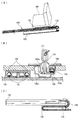
- wire harness
- locking
- protector
- width direction
- seat
- Prior art date
- Legal status (The legal status is an assumption and is not a legal conclusion. Google has not performed a legal analysis and makes no representation as to the accuracy of the status listed.)
- Ceased
Links
Images


Classifications
-
- B—PERFORMING OPERATIONS; TRANSPORTING
- B60—VEHICLES IN GENERAL
- B60R—VEHICLES, VEHICLE FITTINGS, OR VEHICLE PARTS, NOT OTHERWISE PROVIDED FOR
- B60R16/00—Electric or fluid circuits specially adapted for vehicles and not otherwise provided for; Arrangement of elements of electric or fluid circuits specially adapted for vehicles and not otherwise provided for
- B60R16/02—Electric or fluid circuits specially adapted for vehicles and not otherwise provided for; Arrangement of elements of electric or fluid circuits specially adapted for vehicles and not otherwise provided for electric constitutive elements
- B60R16/0207—Wire harnesses
- B60R16/0215—Protecting, fastening and routing means therefor
-
- H—ELECTRICITY
- H02—GENERATION; CONVERSION OR DISTRIBUTION OF ELECTRIC POWER
- H02G—INSTALLATION OF ELECTRIC CABLES OR LINES, OR OF COMBINED OPTICAL AND ELECTRIC CABLES OR LINES
- H02G11/00—Arrangements of electric cables or lines between relatively-movable parts
- H02G11/006—Arrangements of electric cables or lines between relatively-movable parts using extensible carrier for the cable, e.g. self-coiling spring
-
- H—ELECTRICITY
- H02—GENERATION; CONVERSION OR DISTRIBUTION OF ELECTRIC POWER
- H02G—INSTALLATION OF ELECTRIC CABLES OR LINES, OR OF COMBINED OPTICAL AND ELECTRIC CABLES OR LINES
- H02G3/00—Installations of electric cables or lines or protective tubing therefor in or on buildings, equivalent structures or vehicles
- H02G3/02—Details
- H02G3/04—Protective tubing or conduits, e.g. cable ladders or cable troughs
- H02G3/0462—Tubings, i.e. having a closed section
- H02G3/0475—Tubings, i.e. having a closed section formed by a succession of articulated units
Definitions
- the present invention relates to a wiring harness wiring structure, and in particular, is suitably used as a wiring harness wiring structure for a slide seat mounted on a vehicle.
- Automobile seats are equipped with various electrical components such as an electric reclining device and a seat heater.
- a power supply wire harness is routed from the vehicle body floor to the seat.
- the wire harness is provided with an extra length portion.
- FIGS. 8A to 8C a device shown in FIGS. 8A to 8C is proposed in WO / 2010 / 070970A1 (Patent Document 1).
- the harness routing device slidably attaches a support body 101 attached to a seat leg portion of a slide seat 100 to a support rail (seat rail) 105 fixed to the vehicle body floor, as shown in FIG.
- a wire harness 110 in which an electric wire group is sheathed by a corrugated tube 108 is drawn into the support rail 105 from the front end opening in the longitudinal direction of the support rail 105.
- the other end of the wire harness 110 is held by a slider 111 attached to the support 101, pulled out of the support rail 105, and routed to the slide sheet 100. As shown in FIG. 8C, the wire harness 110 pulled out from the front end opening of the support rail 105 is pulled out through the inside of the accommodating portion 130 of the extra harness portion provided on the side of the support rail 105.
- the wire harness that is drawn into the support rail 105 and routed is formed in the left and right side spaces 105b and 105c with the center portion 105a of the upper surface opening interposed therebetween. It passes through the inside of one side space 105b.
- a wire harness covered with a corrugated tube divided into two is inserted into the side spaces 105b and 105c on both sides.
- the wire harness 110 moves within the support rail 105 in conjunction with the slide sheet 100, the support body 101, and the slider 111 within the support rail 105, and a portion pulled out from the support rail 105 moves on the floor panel. Therefore, it is necessary to protect the electric wire group during movement, and the corrugated tube 108 is externally provided over the entire length of the electric wire group.
- the outer diameter of the wire group of the wire harness inserted into the corrugated tube 108 is regulated to be equal to or smaller than the inner diameter of the corrugated tube 108, and the electric wire having the inner diameter or larger. Cannot penetrate the group.
- the present invention has been made in view of the above problems, and in a harness routing structure for a slide seat, the side space of the support rail can be effectively used, and the side space of the support rail can be increased even if the number of wires in the wire harness increases. Is to be used as a wiring route for a wire harness. It is another object of the present invention to provide an inexpensive and lightweight exterior material that is suitably used in the harness wiring structure for the slide sheet and also suitably used for a wire harness that is routed to another location.
- the present invention provides a wiring structure for a wire harness for a slide seat that is provided with an extra length between a fixed position on the vehicle body floor side and a fixed position on the slide seat side. Because Insert a wire harness for power feeding with a group of wires covered with an exterior material made of a protector from a front end opening into a side space of a seat rail that rotatably fits a wheel of a seat leg of the slide seat.
- the wire harness pulled out from the opening is pulled into a U-turn type extra length accommodation box arranged adjacent to the side of the seat rail, and then pulled out to a fixed position on the vehicle body floor side, and the side portion in the seat rail
- the wire harness inserted into the space is pulled out of the seat rail in front of the wheel and led to the slide seat
- the protector made of the protector is an assembly type square cylindrical caterpillar type, and is provided with four folding lines extending in the length direction on the belt-like flat plate at intervals in the intermediate portion in the width direction, and A locking projection is provided on one side of both side edges in the width direction, and a locking hole for inserting and locking the locking projection is provided on the other side, and is bent along the bending line to form a rectangular tube shape.
- a wire harness routing structure is provided in which the three sides of the rectangular tube are separated and connected in a foldable manner.
- the present invention is characterized in that the exterior material of the wire harness that is inserted into the seat rail is an assembly type square cylindrical caterpillar type protector. If the outer shape of the caterpillar type protector is a quadrilateral shape along the inner surface of the side space of the seat rail, the space of the side space of the seat rail can be used effectively, the accommodation volume in the protector can be increased, and the number of electric wires increases It can be made to correspond.
- An arc-shaped bent cutting line is provided in the middle part of the cutting line, and an uneven fitting part is formed between adjacent rectangular tube parts in an assembled state.
- corrugated fitting part is provided between the square tube parts which are isolate
- the assembly-type square cylindrical caterpillar type protector is formed of a thin, strip-shaped flat plate, and is provided with the bent line, the cut line, the locking protrusion, and the locking hole. Moreover, it is preferable that the flat plate is formed as a continuous material, and the flat plate is cut and used according to the length of the wire harness.
- the bending line may be formed in a thin hinge shape with a plate thickness reduced by about 1/3, or may be formed with a punched hole at an interval.
- the incision line and the locking hole are provided by punching a flat plate.
- the assembled square cylindrical caterpillar protector used in the present invention is less expensive than the conventional corrugated tube and is transported. Time is not bulky because it remains flat. Moreover, since it is not a closed cylinder, it can be easily packaged on the wire harness.
- the assembly type square cylindrical caterpillar type protector can be particularly preferably used for the wiring harness wiring structure for the slide seat, and when the wire harness sheathed with the caterpillar type protector is inserted into the seat rail, A narrow space in the seat rail can be effectively used as a wiring space for the wire harness.
- the assembly type square cylindrical caterpillar type protector is inexpensive and lightweight, and is easy to assemble to the wire harness, so it is not limited to the wire harness for feeding power to the slide sheet, but as an exterior material for other wire harnesses Can also be used.
- a second invention it is an exterior material of a wire harness composed of a caterpillar type protector of an assembly type square tube shape that is formed by bending a long plate material in a developed shape, Four bending lines extending in the length direction are provided at intervals in the intermediate portion in the width direction, and a locking protrusion is provided on one side of both side edges in the width direction and on the other side.
- a locking hole for inserting and locking the locking protrusion is provided, bent along the folding line to form a square tube shape, and the locking protrusion is inserted and locked into the locking hole to hold the rectangular tube shape.
- a widthwise cut line connecting the four bent lines is provided at intervals in the length direction, and the three sides of the rectangular tube are separated and connected to be bent.
- the exterior material of the characteristic wire harness is provided.
- the exterior material comprising the above-described caterpillar type protector of the present invention is also suitable for accommodating a wire harness in a bent state when assembling an assembly such as a meter unit to an assembly such as an instrument panel. Used.
- the exterior material of the wire harness made of the caterpillar type protector extends the side provided with the locking hole in the width direction, and has two to three bent lines extending in the length direction in the extended portion. Forming overlapping sides by forming an interval in the width direction, folding the overlapping sides on the inner surfaces of two to three sides of the square tube formed by folding the four folding lines, and A width direction cut line is provided in the overlap side by shifting in the length direction with the width direction cut line crossing the four bent lines, and the overlap side is generated on the outer surface of the square tube. It is good also as a structure which covers a clearance gap.
- the bending line provided in the extension part of the said width direction is made into two, and it covers on the inner surface of 2 sides of a square cylinder, simplification of a structure, weight reduction, and an assembly operation can be simplified.
- the gap generated on the outer side of the three sides of the square tube can be closed.
- a further 6 to 7 bent lines are provided by adding 2 to 3 bent lines to the 4 bent lines, and after assembling into a square tube, 2 to 3 sides are set to 2 to 3 of the square tube.
- the protector that overlaps one side to hide the gap is also suitably used as an exterior material for a wire harness that is routed on a long slide seat, a power slide door, the back of a meter, or the like.
- the exterior material of the wire group of the wire harness of the present invention is the caterpillar type protector of the assembly type square tube shape, it is possible to effectively use a narrow space in the seat rail as a wiring space for the wire harness. it can. In addition, it is inexpensive and lightweight, and has various advantages such as good assembly to the wire harness.
- FIG. 1 It is a schematic perspective view which shows the slide sheet in 1st Embodiment.
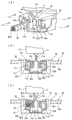
- A is a principal part enlarged view which shows the protector fixed to the front end of a seat leg part
- B is an AA sectional view
- C is a BB sectional drawing.
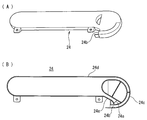
- the extra length accommodation box of the wiring structure of a wire harness is shown
- A) is a perspective view
- B) is a top view of the main body which removed the lid
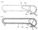
- the wire harness in the said extra length accommodation box is shown
- (A) is a schematic plan view in case a slide seat exists in the backmost position
- (B) is a schematic plan view in case a slide seat exists in the frontmost position. is there.
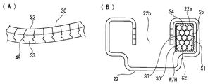
- (A) is a development view of the protector, and (B) is an enlarged cross-sectional view of the main part.
- (A) is a perspective view of the assembled protector
- (B) is sectional drawing of the state which penetrated the protector in the seat rail.
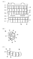
- the exterior material of the wire harness which consists of a protector of 2nd Embodiment is shown
- (A) is an expanded view
- (B) is an assembly drawing
- (C) is a perspective view of a protector.
- (A)-(C) are figures which show a prior art example.
- a wire harness W / H is routed between the vehicle body floor 20 and the slide sheet 10 in order to supply power to an electrical component (not shown) mounted on the slide sheet 10 mounted on the automobile.
- a pair of left and right seat legs 11 as shown in FIG. 2 are provided on the lower surface of the slide seat 10, and each seat leg 11 is slidably attached to a seat rail 22 provided in a recess 21 of the vehicle body floor 20.
- the seat rail 22 includes a pair of left and right wheel passage side spaces 22a and 22a continuous in the length direction and an upper surface opening space 22b positioned therebetween, and the side space 22a has a rectangular cross section with the upper surface closed. Further, an open communication portion 22d that connects the side space 22a and the upper surface opening space 22b is provided below the side wall 22c that separates the side space 22a and the upper surface opening space 22b.
- the seat leg portion 11 has a U-shaped arm portion 11b extending from the shaft portion 11a to the left and right, and supports the wheels 11c on the outer surfaces of the left and right arm portions 11b.
- the shaft portion 11a of the seat leg portion 11 is inserted into the upper surface opening space 22b of the seat rail 22, and the arm portion 11b is passed through the communication portion 22d so that the wheel 11c can freely rotate to the side space 22a for passing the wheel. It is fitted. Thereby, the seat leg portion 11 is slidable on the seat rail 22.
- the vehicle body floor 20 is covered with a floor carpet 20a, and a cover member 23 covers a gap between the floor carpet 20a covering the edge of the recess 21 and the seat rail 22.
- an extra length absorption box 24 composed of a main body and a lid is disposed adjacent to the side portion of the seat rail 22.
- the vehicle harness connection side of the wire harness W / H is fixed to the vehicle body floor 20 near the drawing port 24 a of the extra length absorption box 24 with a clamp 27, and the distal end side of the fixed wire harness W / H is instrumented.
- the connector is connected to an electrical component (not shown) in the instrument panel.
- the surplus length portion of the wire harness W / H drawn through the lead-in port 24a is bent and accommodated in a U shape, and the surplus length absorption box 24 follows the sliding motion of the seat leg portion 11. The extra length part is taken in and out from the entrance 24b.
- the surplus length absorption box 24 has a circular arc passage 24c continuing to the front end side entrance / exit 24b communicated with one side portion of the vertically long U-shaped housing portion 24d, and is drawn into the other side portion.
- An inclined passage 24e communicating with 24a is provided.
- the wire harness W / H pulled out from the entrance / exit 24b of the extra length absorption box 24 is slidably inserted into one wheel passage side space 22a of the seat rail 22.
- the upper surface of the extra length absorption box 24 is also covered with the floor carpet 20a so that it cannot be seen from the outside (vehicle interior).
- the side space 22a of the seat rail 22, the surplus length absorption box 24, and the wire harness W / H drawn to the vehicle body side constitute the wire harness W / H as shown in FIGS.
- the electric wire group is covered with an exterior material made up of an assembly-type square cylindrical caterpillar type protector 30 (hereinafter abbreviated as protector 30).
- protector 30 By covering with the protector 30, the protector 30 is in a state along the inner surface of the side portion of the seat rail surrounding the side space 22a having a rectangular cross section of the seat rail 22 with a gap.
- the shape and assembly method of the protector 30 will be described later.
- the rear end of the protector 30 inserted into the side space 22a of the seat rail 22 is fixed to the front end of the seat leg 11, and the protector 30 is slidably inserted into the side space 22a.
- a drawer member 13 having a J-shaped cross section is provided below the side face behind the protector 30 so that the sheet connection side of the wire group W inserted through the protector 30 through the communication portion 22d is drawn into the upper surface opening space 22b.
- the front end side of the electric wire group W drawn through the protector 30 and the drawing member 13 to the upper surface opening space 22b of the seat rail 22 is connected to an electrical component (not shown) in the slide sheet 10 through a connector.
- the protector 30 is assembled by bending a strip-shaped long material made of a flat plate 40 shown in FIG.
- the long material may be a continuous material, cut to a required length and used, or may be formed with a preset length.
- the flat plate 40 is a thin plate material having a thickness of 0.75 mm to 1.5 mm.
- the flat plate 40 is provided with four bent lines 41, 42, 43, 44 extending in the length direction X at intervals in the middle portion in the width direction Y, and the flat plate 40 is provided with five sides in the width direction. It is divided into S1 to S5, bent lines 41 to 44 are bent at a right angle, and both sides S1 and S5 in the width direction are overlapped so as to be assembled into a square cylinder as shown in FIG.
- locking protrusions 45 are provided on the side edges of one side S1 on both sides in the width direction of the flat plate 40 at intervals in the length direction X.
- the locking protrusion 45 is provided with a notch 45a on both sides of the base of the arcuate protrusion, and the locking side 45b protrudes on both sides.
- An elongated locking hole 46 for inserting and locking the locking protrusion 45 is provided in the other side S5 of the flat plate 40.
- Cuts 46a are provided at both ends in the length direction of the locking holes 46, and small-diameter holes 46c are provided at the tips thereof.
- a locking side 45b is applied to the cut 46a, and a crack is prevented from occurring at the tip of the cut 46a by the small diameter hole 46c.
- the flat plate 40 is bent along the bending lines 41 to 44, and the locking protrusions 45 are inserted and locked into the locking holes 46 with the sides S1 and S5 being overlapped, so that the rectangular tube shape can be maintained. Yes
- the flat plate 40 is provided with cut lines 48 in the width direction Y connecting the four bent lines 41 to 44 with an interval in the length direction X to separate the sides S2, S3 and S4.
- Small diameter holes 48a are continuously provided at both ends of the cutting line 48, that is, at positions where the bending lines 41 and 44 are in contact with each other to prevent cracks from occurring at the tip.
- an arc-shaped cut 49 having a straight line curved at the center of the side S3 is provided at the center of the cut line 48, one side adjacent in the length direction is projected in an arc shape, and the other is formed in an arc shape. Recessed and provided with an uneven fitting part.
- the bending lines 41 to 44 provided on the flat plate 40 are cut into about 1/3 of the plate thickness to form arc-shaped lines.
- the cut line 48, the locking hole 46, and the locking protrusion 45 are all formed by punching a flat plate. Therefore, after the flat plate 40 is formed, it is formed by punching or cutting.
- the locking protrusions 45 are not inserted into the locking holes 46, but are opened on both sides of the protector 30 in which the wire group W of the wire harness W / H is bent. Insert from the opening between sides S1 and S5. After inserting the wire group W, the sides S1 and S5 are overlapped, and the locking protrusion 45 is inserted and locked into the locking hole 46, and the wire group W is externally inserted into the rectangular tube.
- the protector 30 has a configuration in which the three sides S2, S3, and S4 of the square tube are separated in the length direction by the cut line 48, and the overlapping sides S1 and S5 are connected to be bent in the length direction, In addition, the separated side S3 is in a state in which the adjacent sides S3 are concavo-convexly fitted with arcuate cuts. That is, a caterpillar-shaped protector is provided in which short rectangular tubes are sequentially connected in the length direction so that they can be bent, and adjacent square tubes are fitted to each other so that they do not shift in the width direction.
- the exterior material of the wire harness is flexible like a conventional corrugated tube. Since the caterpillar type protector has flexibility, it can be used as an exterior material of the wire harness W / H.
- a rectangular shape is formed along the inner surface of the side space 22 a of the seat rail 22, and the space of the side space 22 a of the seat rail 22 can be effectively used.
- the volume can be increased, and the increase in the electric wire group W can be accommodated.
- FIG. 4A shows a case where the slide seat 10 is at the most rear position
- FIG. 4B shows a case where the slide seat 10 is at the most front position.
- the wire harness W / H can slide the side space 22a of the seat rail 22 while bending the surplus length portion with the surplus length absorption box 24 provided on the side of the seat rail 22, the slide rail for harness is used. Even if it is not newly provided on the vehicle body floor 20, the wire harness W / H can smoothly follow the sliding operation of the seat leg portion 11. Therefore, the harness slide rail is unnecessary, and the increase in cost and weight is suppressed, and the number of rails provided on the vehicle body floor 20 is reduced, so that the appearance can be improved.
- the side space 22a for passing the wheel of the seat rail 22 has a rectangular cross section with the upper surface closed, and the inserted wire harness W / H covers the electric wire group with a square cylindrical caterpillar type protector 30. Therefore, it can be slidably inserted along the wall surface of the side space 22a, and the space of the side space 22a can be used efficiently.
- the wire harness W / H can be prevented from jumping out of the seat rail 22 when the slide seat 10 is operated, and the wire harness W / H can be protected from being stepped on.
- FIG. 7 shows an assembled square cylindrical caterpillar type protector 50 according to the second embodiment.
- the protector 50 according to the second embodiment hides the gap generated in the outer cut line 48 when the protector 30 according to the first embodiment is bent in the length direction, and dust and dust are contained in the protector 50 from the gap. I try not to enter.
- the protector 50 of the second embodiment extends in the width direction the side S5 provided with the locking hole 46 of the assembly-type square cylindrical protector 30 of the first embodiment, and extends in the length direction to the extended portion 51.
- Two folding lines 53 and 54 are provided, and two overlapping sides S6 and S7 partitioned by the bending lines are provided.
- the overlapping sides S6 and S7 are set to dimensions that are folded over the inner surfaces of the two sides S2 and S3 of the square tube formed by bending the four folding lines 41 to 44.
- the extended portion 51 is displaced in the length direction (X) from the cut line 48 in the width direction (Y) provided between the four bent lines 41 to 44, and the bent line 53 From the extending portion 51 to the front end in the width direction, a cut line 58 continuous in the width direction is provided in the overlapping pieces S6 and S7. That is, the cut lines 58 are provided in a staggered arrangement at positions between the cut lines 48 adjacent in the length direction (X).
- Other configurations, such as the provision of the locking protrusion 45 from the edge of the side S1 are the same as those in the first embodiment, and the description thereof will be omitted by assigning the same reference numerals.
- the locking protrusions 45 are assembled by assembling as a rectangular tube with the folding lines 41 to 44. After being inserted into the locking hole 46 and locked, as shown in FIG. 7B, it is bent along the folding lines 53 and 54, the side S6 is overlapped with the inner surface of the side S2, and the side S7 is overlapped with the side S3. Yes.
- three bent lines may be provided in the extended portion and overlapped with the three sides of the square tube.
- the engagement side of the sides S1 and S5 not provided with the cutting line 48 is the inner peripheral surface at the time of bending
- the three sides of the extended portion are overlapped with the three sides which are the outer peripheral surface and the upper and lower surfaces, Clearance generated in the protector can be eliminated without fail.
- the assembly type square cylindrical caterpillar type protectors 30 and 50 are not limited to the exterior material of the wire harness for the slide sheet of the embodiment, and are preferably used as the exterior material of the wire harness that needs to be bent. be able to.
Landscapes
- Engineering & Computer Science (AREA)
- Mechanical Engineering (AREA)
- Architecture (AREA)
- Civil Engineering (AREA)
- Structural Engineering (AREA)
- Details Of Indoor Wiring (AREA)
- Electric Cable Arrangement Between Relatively Moving Parts (AREA)
- Seats For Vehicles (AREA)
Abstract
スライドシートに接続する給電用のワイヤハーネスの外装材を改良して配索スペースに効率よく配索できるようにする。スライドシート用のシートレールの側部空間にワイヤハーネスを挿通し、該ワイヤハーネスに組立式四角筒状のキャタピラ型のプロテクタを外装し、該プロテクタは帯状の平板に長さ方向に延在する4本の折曲ラインを幅方向の中間部に間隔をあけて設け、かつ、該幅方向の両側縁の一方側に係止突片を突設すると共に他方側に前記係止突片を挿入係止する係止穴を設け、前記折曲ラインに沿って折り曲げて四角筒形状とすると共に係止突片を係止穴に挿入係止して四角筒状を保持し、さらに、前記4本の折曲ラインを結ぶ幅方向の切込ラインを長さ方向に間隔をあけて設けて四角筒の3辺を分離して折り曲げ自在に連結された形状としている。
Description
本発明はワイヤハーネス配索構造に関し、特に、車両に搭載されるスライドシート用のワイヤハーネスの配索構造として好適に用いられるものである。
自動車のシートには電動リクライニング装置やシートヒータなど種々の電装品が装備されており、これらの電装品に給電するために、車体フロアからシートに給電用のワイヤハーネスが配索されている。スライドシートの場合には、ワイヤハーネスをシートのスライド動作に追従させる必要があり、そのためワイヤハーネスに余長部を持たせて配索している。
従来、この種の車体フロアとスライドシートとの間に配索するハーネス配索装置として、WO/2010/070970A1号公報(特許文献1)で図8(A)~(C)に示す装置が提案されている。該ハーネス配索装置は、スライドシート100のシート脚部に取り付けた支持体101を車体フロアに固定された支持レール(シートレール)105にスライド自在に取り付け、図8(B)に示すように、支持レール105の長手方向の前端開口からコルゲートチューブ108で電線群を外装したワイヤハーネス110を、支持レール105の内部に引き込んでいる。該ワイヤハーネス110の他端を支持体101に取り付けたスライダ111で保持して支持レール105外に引き出し、スライドシート100へと配索している。支持レール105の前端開口から引き出されたワイヤハーネス110は図8(C)に示すように、支持レール105の側方に設けたハーネス余長部分の収容部130内を通して外部へ引き出されている。
詳細には、前記支持レール105の内部に引き込んで配索するワイヤハーネスは、図8(B)に示す実施形態では、上面開口の中央部105aを挟んだ左右両側の側部空間105b、105cの一方の側部空間105bの内部に挿通している。他の実施形態では、2本に分割したコルゲートチューブで外装したワイヤハーネスを両側の側部空間105bと105cに挿通している。
前記ワイヤハーネス110は、支持レール105内でスライドシート100、支持体101及びスライダ111と連動して支持レール105の内部を移動すると共に、支持レール105から引き出された部分はフロアパネル上を移動するため、移動時に電線群を保護する必要があり、コルゲートチューブ108が電線群の全長に外装されている。
しかしながら、特許文献1に開示されている断面丸型のコルゲートチューブ108の場合、コルゲートチューブ108内に挿通するワイヤハーネスの電線群の外径がコルゲートチューブ108の内径以下に規制され、内径以上の電線群を挿通することができない。かつ、コルゲートチューブが支持レール105の側部空間105b内をスムーズに移動できるように、コルゲートチューブの山部外面と側部空間を囲む支持レールの内面に隙間を設ける必要もあり、四角形状の側部空間に丸型のコルゲートチューブを挿通すると、側部空間を有効に利用できない。
特に、スライドシートに付設する電装品が急増し、スライドシートに接続する給電用の電線本数が増加しているため、支持レール内の空間をワイヤハーネスの配索スペースとして有効利用する必要があり、その点でコルゲートチューブを外装材として用いることに問題がある。
しかしながら、特許文献1に開示されている断面丸型のコルゲートチューブ108の場合、コルゲートチューブ108内に挿通するワイヤハーネスの電線群の外径がコルゲートチューブ108の内径以下に規制され、内径以上の電線群を挿通することができない。かつ、コルゲートチューブが支持レール105の側部空間105b内をスムーズに移動できるように、コルゲートチューブの山部外面と側部空間を囲む支持レールの内面に隙間を設ける必要もあり、四角形状の側部空間に丸型のコルゲートチューブを挿通すると、側部空間を有効に利用できない。
特に、スライドシートに付設する電装品が急増し、スライドシートに接続する給電用の電線本数が増加しているため、支持レール内の空間をワイヤハーネスの配索スペースとして有効利用する必要があり、その点でコルゲートチューブを外装材として用いることに問題がある。
また、一般的に、ワイヤハーネスの電線の外装材としてコルゲートチューブを用いると、従来の粘着テープを巻き付ける場合と比較して、嵩高になると共にコスト高になり、かつ、重量も増大する等の問題もあり、該問題を解消できる外装材が求められている。
本発明は前記問題に鑑みてなされたもので、スライドシート用のハーネス配索構造において、支持レールの側部空間を有効利用でき、ワイヤハーネスの電線本数が増加しても支持レールの側部空間をワイヤハーネスの配索経路として利用できるようにすることを課題としている。また、該スライドシート用のハーネス配索構造において好適に用いられると共に、他の箇所に配索するワイヤハーネス用としても好適に用いられる安価かつ軽量な外装材を提供することを課題としている。
前記課題を解決するため、本発明は、車体フロア側の固定位置とスライドシート側の固定位置との間で余長部を持たせて配索しているスライドシート用のワイヤハーネスの配索構造であって、
前記スライドシートのシート脚部の車輪を回転自在に嵌合するシートレールの側部空間に、プロテクタからなる外装材で電線群を外装した給電用のワイヤハーネスを先端開口から挿入すると共に、該先端開口から引き出される前記ワイヤハーネスを前記シートレールの側方に隣接して配置したUターン式の余長収容ボックスに引き込んだ後に前記車体フロア側の固定位置へと引き出し、前記シートレール内の側部空間に挿入した前記ワイヤハーネスは前記車輪の前方でシートレール外に引き出してスライドシートヘ導出しており、
前記プロテクタからなる外装材は組立式四角筒状のキャタピラ型とし、帯状の平板に長さ方向に延在する4本の折曲ラインを幅方向の中間部に間隔をあけて設け、かつ、該幅方向の両側縁の一方側に係止突片を突設すると共に他方側に前記係止突片を挿入係止する係止穴を設け、前記折曲ラインに沿って折り曲げて四角筒形状とすると共に係止突片を係止穴に挿入係止して四角筒状を保持し、さらに、前記4本の折曲ラインを結ぶ幅方向の切込ラインを長さ方向に間隔をあけて設けて四角筒の3辺を分離して折り曲げ自在に連結された形状としていることを特徴とするワイヤハーネス配索構造を提供している。
前記スライドシートのシート脚部の車輪を回転自在に嵌合するシートレールの側部空間に、プロテクタからなる外装材で電線群を外装した給電用のワイヤハーネスを先端開口から挿入すると共に、該先端開口から引き出される前記ワイヤハーネスを前記シートレールの側方に隣接して配置したUターン式の余長収容ボックスに引き込んだ後に前記車体フロア側の固定位置へと引き出し、前記シートレール内の側部空間に挿入した前記ワイヤハーネスは前記車輪の前方でシートレール外に引き出してスライドシートヘ導出しており、
前記プロテクタからなる外装材は組立式四角筒状のキャタピラ型とし、帯状の平板に長さ方向に延在する4本の折曲ラインを幅方向の中間部に間隔をあけて設け、かつ、該幅方向の両側縁の一方側に係止突片を突設すると共に他方側に前記係止突片を挿入係止する係止穴を設け、前記折曲ラインに沿って折り曲げて四角筒形状とすると共に係止突片を係止穴に挿入係止して四角筒状を保持し、さらに、前記4本の折曲ラインを結ぶ幅方向の切込ラインを長さ方向に間隔をあけて設けて四角筒の3辺を分離して折り曲げ自在に連結された形状としていることを特徴とするワイヤハーネス配索構造を提供している。
本発明では、シートレール内に挿通するワイヤハーネスの外装材を組立式四角筒状のキャタピラ型のプロテクタとしていることを特徴としている。該キャタピラ型プロテクタの外形をシートレールの側部空間の内面に沿った四角形状とすると、該シートレールの側部空間のスペースを有効利用でき、プロテクタ内の収容容積も増大でき、電線群の増加に対応させることができる。
前記切込ラインの中間部に円弧状の屈曲切込ラインを設け、組立状態で隣接する四角筒部の間に凹凸嵌合部を形成している。
このように、互いに切込ラインで分離されると共に隣接する四角筒部の間に凹凸嵌合部を設けると、隣接した四角筒部が左右方向及び前後方向に大きく位置ずれさせることなく連結できる。
このように、互いに切込ラインで分離されると共に隣接する四角筒部の間に凹凸嵌合部を設けると、隣接した四角筒部が左右方向及び前後方向に大きく位置ずれさせることなく連結できる。
前記組立式四角筒状のキャタピラ型プロテクタは、展開形状で薄肉の帯状の平板からなり、該平板に前記折曲ライン、切込ライン、係止突片、係止穴を設けている。また、前記平板を連続材として形成し、ワイヤハーネスの長さに応じて前記平板を切断して用いることが好ましい。
前記折曲ラインは、板厚を1/3程度薄くして、薄肉ヒンジ状に形成してもよいし、間隔をあけて打抜穴を設けて形成してもよい。前記切込ラインおよび係止穴は平板を打ち抜き加工して設けている。
このように、平板を打抜加工して形成し、これを折り曲げて組み立てるだけであるため、本発明で用いる組立式四角筒状のキャタピラ型プロテクタは従来のコルゲートチューブより安価であり、かつ、運搬時は平板形状のままであるため嵩ばらない。しかも、閉鎖された筒状でないため、ワイヤハーネスに容易に外装することができる。
前記のように、組立式四角筒状のキャタピラ型プロテクタはスライドシート用のワイヤハーネス配索構造に特に好適に用いることができ、該キャタピラ型プロテクタで外装したワイヤハーネスをシートレール内に挿通すると、シートレール内の狭いスペースをワイヤハーネスの配索空間として有効利用することができる。
しかしながら、組立式四角筒状のキャタピラ型プロテクタは安価かつ軽量で、しかもワイヤハーネスへの組付性がよいため、スライドシートへ給電用のワイヤハーネスに限定されず、他のワイヤハーネスの外装材としても用いることができる。
しかしながら、組立式四角筒状のキャタピラ型プロテクタは安価かつ軽量で、しかもワイヤハーネスへの組付性がよいため、スライドシートへ給電用のワイヤハーネスに限定されず、他のワイヤハーネスの外装材としても用いることができる。
よって、第2の発明として、展開形状で平板の長尺材を折り曲げて形成する組立式四角筒状のキャタピラ型プロテクタからなるワイヤハーネスの外装材であり、
長さ方向に延在する4本の折曲ラインを幅方向の中間部に間隔をあけて設け、かつ、該幅方向の両側縁の一方側に係止突片を突設すると共に他方側に前記係止突片を挿入係止する係止穴を設け、前記折曲ラインに沿って折り曲げて四角筒形状とすると共に係止突片を係止穴に挿入係止して四角筒状を保持し、さらに、前記4本の折曲ラインを結ぶ幅方向の切込ラインを長さ方向に間隔をあけて設けて四角筒の3辺を分離して折り曲げ自在に連結された形状としていることを特徴とするワイヤハーネスの外装材を提供している。
長さ方向に延在する4本の折曲ラインを幅方向の中間部に間隔をあけて設け、かつ、該幅方向の両側縁の一方側に係止突片を突設すると共に他方側に前記係止突片を挿入係止する係止穴を設け、前記折曲ラインに沿って折り曲げて四角筒形状とすると共に係止突片を係止穴に挿入係止して四角筒状を保持し、さらに、前記4本の折曲ラインを結ぶ幅方向の切込ラインを長さ方向に間隔をあけて設けて四角筒の3辺を分離して折り曲げ自在に連結された形状としていることを特徴とするワイヤハーネスの外装材を提供している。
前記した本発明のキャタピラ型プロテクタからなる外装材はメータユニット等の組付体をインストルメントパネル等の被組付体に組みつける際に、ワイヤハーネスを屈曲状態で収容する場合等にも好適に用いられる。
また、前記キャタピラ型プロテクタからなるワイヤハーネスの外装材は、前記係止穴を設けた辺を幅方向に延長し、該延長部分に長さ方向に延在する2~3本の折曲ラインを幅方向に間隔をあけて形成して重ね辺を設け、これら重ね辺を前記4本の折曲ラインで折り曲げて形成する四角筒の2~3つの辺の内面に重ねて折り曲げるようにし、かつ、前記4本の折曲ラインを横断する前記幅方向の切込ラインと長さ方向で位置ずれさせて前記重ね辺に幅方向の切込ラインを設け、該重ね辺で前記四角筒の外面に生じる隙間を覆う構成としてもよい。
四角筒を折り曲げて形成し、かつ、該四角筒を長さ方向で屈曲させると、外周側となる辺には前記切込ラインに隙間が発生する。この隙間を延長した重ね辺で覆うと、隙間を通してゴミやホコリがプロテクタ内に侵入するのを防止できる。よって、シートレール内に挿入するプロテクタ内にゴミやホコリが侵入して蓄積し、ワイヤハーネスの移動を阻害するのを防止できる。さらにまた、前記隙間を通して鋭利な外部干渉材が内部に突き刺さり、ワイヤハーネスに損傷を与えることをも防止できる。
なお、前記幅方向の延長部に設ける折曲ラインは2本とし、四角筒の2辺の内面にかさねるようにすると、構成の簡易化、軽量化および組立作業を簡単にすることができる。
一方、前記幅方向の延長部に設ける折曲ラインは3本とし、四角筒の3辺の内面にかさねるようにすると、四角筒の3辺の外面に生じる隙間を閉鎖することができる。
一方、前記幅方向の延長部に設ける折曲ラインは3本とし、四角筒の3辺の内面にかさねるようにすると、四角筒の3辺の外面に生じる隙間を閉鎖することができる。
前記4本の折曲ラインに更に2~3本の折曲ラインを加えて合計6~7本の折曲ラインを設け、四角筒に組み立てた後に2~3つの辺を四角筒の2~3つの辺に重ねて隙間を隠すようにした前記プロテクタも、ロングスライドシート、パワースライドドア、メータ裏等に配索するワイヤハーネスの外装材として好適に用いられる。
前記のように、本発明のワイヤハーネスの電線群の外装材は前記組立式四角筒状のキャタピラ型プロテクタとしているため、シートレール内の狭いスペースをワイヤハーネスの配索空間として有効利用することができる。かつ、安価、軽量であると共に、ワイヤハーネスへの組付性がよい等の種々の利点を有するものである。
以下、本発明の実施形態を図面を参照して説明する。
図1乃至図6に本発明の第1実施形態を示す。
実施形態は自動車に搭載するスライドシート10に装着した電装品(図示せず)に給電するために、車体フロア20とスライドシート10との間にワイヤハーネスW/Hを配索している。スライドシート10の下面には図2に示すようなシート脚部11を左右一対設けており、各シート脚部11を車体フロア20の凹部21に設けたシートレール22にスライド自在に取り付けている。
図1乃至図6に本発明の第1実施形態を示す。
実施形態は自動車に搭載するスライドシート10に装着した電装品(図示せず)に給電するために、車体フロア20とスライドシート10との間にワイヤハーネスW/Hを配索している。スライドシート10の下面には図2に示すようなシート脚部11を左右一対設けており、各シート脚部11を車体フロア20の凹部21に設けたシートレール22にスライド自在に取り付けている。
シートレール22は長さ方向に連続する左右一対の車輪通過の側部空間22a、22aとその間に位置する上面開口空間22bを備え、側部空間22aは上面が閉鎖された断面矩形状としている。また、側部空間22aと上面開口空間22bとを隔てる側壁22cの下側に、側部空間22aと上面開口空間22bとを連通させる開口状の連通部22dを設けている。
シート脚部11は、軸部11aから断面U字形状の腕部11bを左右に延在させ、左右の腕部11bの外面に車輪11cを軸支している。シート脚部11の軸部11aをシートレール22の上面開口空間22bに挿通すると共に、腕部11bを連通部22dに通すことで、車輪11cを車輪通過用の側部空間22aに回動自在に嵌合させている。これにより、シート脚部11をシートレール22にスライド自在としている。一方、車体フロア20はフロアカーペット20aで被覆され、凹部21端縁を覆うフロアカーペット20aとシートレール22との間の隙間をカバー材23で覆っている。
また、図1、図3及び図4に示すように、シートレール22の側部に隣接して、本体と蓋とからなる余長吸収ボックス24を配置している。図1に示すように、ワイヤハーネスW/Hの車体接続側は余長吸収ボックス24の引込口24a付近の車体フロア20にクランプ27で固定し、固定したワイヤハーネスW/Hの先端側をインストルメントパネル内の電装品(図示せず)とコネクタ接続している。余長吸収ボックス24では、引込口24aより引き込まれたワイヤハーネスW/Hの余長部をU形状に屈曲させて収容し、シート脚部11のスライド動作に追従して余長吸収ボックス24の出入口24bから余長部の出し入れを行っている。
余長吸収ボックス24は図3(B)に示すように、前端側の出入口24bに連続する円弧通路24cが縦長なU形状の収容部24dの一側部に連通し、他側部に引込口24aと連通する傾斜通路24eを設けている。
前記余長吸収ボックス24の出入口24bから引き出されたワイヤハーネスW/Hを前記シートレール22の一方の車輪通過用の側部空間22aにスライド自在に挿通している。なお、余長吸収ボックス24の上面もフロアカーペット20aで被覆し、外部(車室内)から見えないようにしている。
前記シートレール22の側部空間22a、余長吸収ボックス24、さらに車体側に引き出されるワイヤハーネスW/Hは、図2、図5、図6に示すように、ワイヤハーネスW/Hを構成する電線群を組立式四角筒状のキャタピラ型プロテクタ30(以下、プロテクタ30と略す)からなる外装材で外装している。該プロテクタ30で外装することで、シートレール22の断面矩形状の側部空間22aを囲むシートレールの側部内面にプロテクタ30が隙間をあけて沿った状態としている。該プロテクタ30の形状および組み立て方は後述する。
前記シートレール22の側部空間22aに挿入したプロテクタ30の後端はシート脚部11の前端に固定し、該プロテクタ30を側部空間22aにスライド自在に挿通している。また、該プロテクタ30の後方の側面下方に、連通部22dを通してプロテクタ30に挿通される電線群Wのシート接続側を上面開口空間22bに引き出す断面J字形状の引出部材13を突設している。プロテクタ30および引出部材13を通ってシートレール22の上面開口空間22bに引き出された電線群Wの先端側をスライドシート10内の電装品(図示せず)とコネクタ接続している。
前記プロテクタ30は、図5に示す平板40からなる帯状の長尺材を折り曲げて組み立てている。該長尺材は連続材とし、所要の長さに切断して用いてもよいし、予め設定した長さで成形してもよい。該平板40の板厚は0.75mm~1.5mmの薄板材としている。
平板40には、長さ方向Xに延在する4本の折曲ライン41、42、43、44を幅方向Yの中間部に間隔をあけて設け、平板40を幅方向に5個の辺S1~S5に区画し、折曲ライン41~44を直角に折り曲げ、幅方向の両側辺S1とS5を重ねることで図6に示すように、四角筒状に組み立てられるようにしている。
また、平板40の幅方向の両側の一方側の辺S1の側縁に係止突片45を長さ方向Xに間隔をあけて突設している。該係止突片45は円弧状の突出部の根元両側に切込45aを設け、両側に係止辺45bが突出する形状としている。平板40の他方側の辺S5に係止突片45を挿入係止する細長い係止穴46を設けている。該係止穴46の長さ方向両端に切込46aを設け、その先端に小径穴46cを設けている。前記切込46aに係止辺45bがかかるようにし、かつ、小径穴46cで切込46aの先端から亀裂が生じないようにしている。平板40を折曲ライン41~44に沿って折り曲げ、辺S1とS5を重ねた状態で係止突片45を係止穴46に挿入係止することで、四角筒形状を保持できるようにしている。
平板40には前記4本の折曲ライン41~44を結ぶ幅方向Yの切込ライン48を長さ方向Xに間隔をあけて設け、辺S2、S3、S4を分離している。該切込ライン48の両端、すなわち、折曲ライン41および44と接する位置には小径穴48aを連続して設け、先端からの亀裂発生を防止している。さらに、切込ライン48の中央部で辺S3の中央位置に直線を湾曲させた円弧状の切込49を設け、長さ方向に隣接する一方側を円弧状に突出させ、他方を円弧状に窪ませ、凹凸嵌合部を設けている。
平板40に設ける折曲ライン41~44は、図5(B)に示すように、板厚の1/3程度を切削して断面円弧状のラインとしている。
前記切込ライン48、係止穴46、係止突片45はすべて平板を打抜いて形成している。
よって、平板40を成形した後に、打抜加工、切削加工で形成している。
前記切込ライン48、係止穴46、係止突片45はすべて平板を打抜いて形成している。
よって、平板40を成形した後に、打抜加工、切削加工で形成している。
前記プロテクタ30は予め折曲ライン41~44を折り曲げる一方、係止突片45は係止穴46に挿入せず、開いた状態でワイヤハーネスW/Hの電線群Wを折り曲げたプロテクタ30の両側辺S1とS5の間の開口から挿入する。この電線群Wの挿入後に辺S1とS5を重ね、係止突片45を係止穴46に挿入係止し、電線群Wを四角筒の中に挿入した状態に外装する。
前記プロテクタ30は四角筒の3辺S2、S3、S4が切込ライン48で長さ方向で分離され、重ねて係止した辺S1とS5が長さ方向で屈曲自在に連結された構成となり、かつ、分離された辺S3は、隣接する辺S3同士が円弧状切込で凹凸嵌合する状態となる。即ち、短尺な四角筒が屈曲自在に長さ方向に順次連結し、かつ、隣接する四角筒同士を凹凸嵌合させているため幅方向にずれない、キャタピラ状のプロテクタとなる。
前記シートレール22の側部空間22aから余長吸収ボックス24を通して車体側へと引き出すワイヤハーネスW/Hは屈曲しながらスライドするため、ワイヤハーネスの外装材は従来のコルゲートチューブのように屈曲性を有する必要があり、前記キャタピラ型のプロテクタは屈曲性を有するため、ワイヤハーネスW/Hの外装材として用いることができる。
また、前記キャタピラ型のプロテクタ30を用いると、シートレール22の側部空間22aの内面に沿った四角形状となり、該シートレール22の側部空間22aのスペースを有効利用でき、プロテクタ30内の収容容積を増大でき、電線群Wの増加に対応させることができる。
次に、スライドシート10のスライド動作に追従するワイヤハーネスW/Hの動きについて説明する。
図4(A)はスライドシート10が最も後方位置にある場合を示し、図4(B)はスライドシート10が最も前方位置にある場合を示す。スライドシート10のシート脚部11を前方から後方へとスライドさせていくと、余長吸収ボックス24内に収容されていたワイヤハーネスW/Hが出入口24bから引き出されシートレール22の側部空間22aに挿通されると共に、余長吸収ボックス24内のワイヤハーネスW/HのU形状の屈曲部が余長吸収ボックス24の前方側へ移動する。一方、スライドシート10のシート脚部11を後方から前方へスライドさせていくと、余長吸収ボックス24内のU形状の屈曲部が余長吸収ボックス24の後方側へ移動すると共に、シートレール22の側部空間22aに挿通されていたワイヤハーネスW/Hが出入口24bから余長吸収ボックス24内へと引き込まれ余長部として収容される。
このように、ワイヤハーネスW/Hはシートレール22の側方に設けた余長吸収ボックス24で余長部を屈曲させながらシートレール22の側部空間22aをスライドできるため、ハーネス用スライドレールを新たに車体フロア20に設けなくても、シート脚部11のスライド動作にワイヤハーネスW/Hを滑らかに追従させることができる。よって、ハーネス用スライドレールが不要となり、その分のコストや重量の増加が抑えられ、さらに、車体フロア20に設けられるレール数が減少するため、見栄えも改善することができる。
特に、シートレール22の車輪通過用の側部空間22aは上面が閉鎖された断面矩形状であり、挿通されるワイヤハーネスW/Hは電線群を四角筒状のキャタピラ型のプロテクタ30で外装しているため、側部空間22aの壁面に添わせてスライド自在に挿通させ、側部空間22aのスペースを効率良く利用できる。かつ、スライドシート10の作動時等にワイヤハーネスW/Hがシートレール22から外側に飛び出すことが防止でき、ワイヤハーネスW/Hを踏み付け等から保護することができる。
図7に第2実施形態の組立式四角筒状のキャタピラ型のプロテクタ50を示す。
該第2実施形態のプロテクタ50は第1実施形態のプロテクタ30を長さ方向で湾曲した時に外周側の切込ライン48で発生する隙間を隠すようにし、隙間からゴミやホコリがプロテクタ50内に入らないようにしている。
該第2実施形態のプロテクタ50は第1実施形態のプロテクタ30を長さ方向で湾曲した時に外周側の切込ライン48で発生する隙間を隠すようにし、隙間からゴミやホコリがプロテクタ50内に入らないようにしている。
第2実施形態のプロテクタ50は前記第1実施形態の組立式四角筒状プロテクタ30の前記係止穴46を設けた辺S5を幅方向に延長し、該延長部分51に長さ方向に延在する2本の折曲ライン53、54を設け、該折曲ラインで区画した2つの重ね辺S6、S7を設けている。これら重ね辺S6、S7を前記4本の折曲ライン41~44で折り曲げて形成する四角筒の2つの辺S2、S3の内面に重ねて折り曲げる寸法に設定している。
また、延長部分51には、前記4本の折曲ライン41~44の間に設けた幅方向(Y)の切込ライン48と長さ方向(X)で位置ずれさせて、折曲ライン53から延長部分51の幅方向の先端まで、重ね片S6、S7に幅方向に連続した切込ライン58を設けている。即ち、長さ方向(X)に隣接する切込ライン48の間の位置に切込ライン58を千鳥配置で設けている。
辺S1の端縁から係止突片45を設けているなど、他の構成は第1実施形態と同様であり、同一符号を付して説明を省略する。
辺S1の端縁から係止突片45を設けているなど、他の構成は第1実施形態と同様であり、同一符号を付して説明を省略する。
前記のように、第2実施形態では、幅方向(Y)に折曲ライン41~44、53、54と6本設け、折曲ライン41~44で四角筒として組み立てて係止突片45を係止穴46に差し込んで係止した後に、図7(B)に示すように、折曲ライン53、54で折り曲げて、辺S6を辺S2の内面に重ね、辺S7を辺S3に重ねている。
辺S6および辺S7に設ける切込ライン58は切込ライン48と位置ずれさせているため、図7(C)に示すように、プロテクタ50を湾曲しても外周側の同一箇所に隙間は発生しない。即ち、内側の切込ライン58で発生する隙間を外側の辺S2、S3が被さって隠すことができる。逆で外側の切込ライン48で発生する隙間を内側の辺S6、S7で閉鎖することができる。
なお、辺S1とS5とが係止する辺には切込ライン48が無いため隙間は発生せず、辺S2がプロテクタの湾曲時に外周側の辺になると、辺S4は内周側の辺となり、よって切込ライン48に隙間は発生しない。よって、辺S2と辺S3の内面に辺S6と辺S7を被せるだけで、プロテクタに隙間を発生させないようにできる。
なお、辺S1とS5とが係止する辺には切込ライン48が無いため隙間は発生せず、辺S2がプロテクタの湾曲時に外周側の辺になると、辺S4は内周側の辺となり、よって切込ライン48に隙間は発生しない。よって、辺S2と辺S3の内面に辺S6と辺S7を被せるだけで、プロテクタに隙間を発生させないようにできる。
なお、延長部分に3本の折曲ラインを設け、四角筒の3つの辺に重ねるようにしてもよい。その場合、切込ライン48を設けていない辺S1とS5との係止辺を湾曲時の内周面とすると、外周面および上下面となる3辺に延長部分の3つの辺を重ねると、プロテクタに発生する隙間を確実に無くすことができる。
なお、前記組立式四角筒状のキャタピラ型のプロテクタ30、50は、前記実施形態のスライドシート用のワイヤハーネスの外装材に限定されず、屈曲させる必要があるワイヤハーネスの外装材として好適に用いることができる。
10 スライドシート
11 シート脚部
13 引出部材
20 車体フロア
22 シートレール
22a 側部空間
24 余長吸収ボックス
30、50 キャタピラ型のプロテクタ
40 平板
41~44、53、54 折曲ライン
45 係止突片
46 係止穴
48、58 切込ライン
51 延長部分
11 シート脚部
13 引出部材
20 車体フロア
22 シートレール
22a 側部空間
24 余長吸収ボックス
30、50 キャタピラ型のプロテクタ
40 平板
41~44、53、54 折曲ライン
45 係止突片
46 係止穴
48、58 切込ライン
51 延長部分
Claims (4)
- 車体フロア側の固定位置とスライドシート側の固定位置との間で余長部を持たせて配索しているスライドシート用のワイヤハーネスの配索構造であって、
前記スライドシートのシート脚部の車輪を回転自在に嵌合するシートレールの側部空間に、プロテクタからなる外装材で電線群を外装した給電用のワイヤハーネスを先端開口から挿入すると共に、該先端開口から引き出される前記ワイヤハーネスを前記シートレールの側方に隣接して配置したUターン式の余長収容ボックスに引き込んだ後に前記車体フロア側の固定位置へと引き出し、前記シートレール内の側部空間に挿入した前記ワイヤハーネスは前記車輪の前方でシートレール外に引き出してスライドシートヘ導出しており、
前記プロテクタからなる外装材は組立式四角筒状のキャタピラ型とし、帯状の平板に長さ方向に延在する4本の折曲ラインを幅方向の中間部に間隔をあけて設け、かつ、該幅方向の両側縁の一方側に係止突片を突設すると共に他方側に前記係止突片を挿入係止する係止穴を設け、前記折曲ラインに沿って折り曲げて四角筒形状とすると共に係止突片を係止穴に挿入係止して四角筒状を保持し、さらに、前記4本の折曲ラインを結ぶ幅方向の切込ラインを長さ方向に間隔をあけて設けて四角筒の3辺を分離して折り曲げ自在に連結された形状としていることを特徴とするワイヤハーネス配索構造。 - 前記切込ラインの中間部に円弧状の屈曲切込ラインを設け、組立状態で隣接する四角筒部の間に凹凸嵌合部を形成している請求項1に記載のワイヤハーネス配索構造。
- 展開形状で平板の長尺材を折り曲げて形成する組立式四角筒状のキャタピラ型プロテクタからなるワイヤハーネスの外装材であり、
長さ方向に延在する4本の折曲ラインを幅方向の中間部に間隔をあけて設け、かつ、該幅方向の両側縁の一方側に係止突片を突設すると共に他方側に前記係止突片を挿入係止する係止穴を設け、前記折曲ラインに沿って折り曲げて四角筒形状とすると共に係止突片を係止穴に挿入係止して四角筒状を保持し、さらに、前記4本の折曲ラインを結ぶ幅方向の切込ラインを長さ方向に間隔をあけて設けて四角筒の3辺を分離して折り曲げ自在に連結された形状としていることを特徴とするワイヤハーネスの外装材。 - 前記係止穴を設けた辺を幅方向に延長し、該延長部分に長さ方向に延在する2~3本の折曲ラインを幅方向に間隔をあけて形成して重ね辺を設け、これら重ね辺を前記4本の折曲ラインで折り曲げて形成する四角筒の2~3つの辺の内面に重ねて折り曲げるようにし、かつ、前記4本の折曲ラインを横断する前記幅方向の切込ラインと長さ方向で位置ずれさせて前記重ね辺に幅方向の切込ラインを設け、該重ね辺で前記四角筒の外面に生じる隙間を覆う構成としている請求項3に記載の外装材。
Priority Applications (1)
| Application Number | Priority Date | Filing Date | Title |
|---|---|---|---|
| CN201280037427.8A CN103717455B (zh) | 2011-08-02 | 2012-02-15 | 线束布设结构 |
Applications Claiming Priority (4)
| Application Number | Priority Date | Filing Date | Title |
|---|---|---|---|
| JP2011-169560 | 2011-08-02 | ||
| JP2011169560 | 2011-08-02 | ||
| JP2011203719A JP2013049402A (ja) | 2011-08-02 | 2011-09-16 | ワイヤハーネス配索構造 |
| JP2011-203719 | 2011-09-16 |
Publications (1)
| Publication Number | Publication Date |
|---|---|
| WO2013018384A1 true WO2013018384A1 (ja) | 2013-02-07 |
Family
ID=47628929
Family Applications (1)
| Application Number | Title | Priority Date | Filing Date |
|---|---|---|---|
| PCT/JP2012/053493 Ceased WO2013018384A1 (ja) | 2011-08-02 | 2012-02-15 | ワイヤハーネス配索構造 |
Country Status (3)
| Country | Link |
|---|---|
| JP (1) | JP2013049402A (ja) |
| CN (1) | CN103717455B (ja) |
| WO (1) | WO2013018384A1 (ja) |
Cited By (3)
| Publication number | Priority date | Publication date | Assignee | Title |
|---|---|---|---|---|
| JP2014166008A (ja) * | 2013-02-22 | 2014-09-08 | Sumitomo Wiring Syst Ltd | スライドシート用のワイヤハーネス配索装置 |
| WO2016114183A1 (ja) * | 2015-01-13 | 2016-07-21 | 株式会社オートネットワーク技術研究所 | 電線保護部材、電線保護部材付ワイヤーハーネス及びスライド配線装置 |
| JP2024121953A (ja) * | 2023-02-28 | 2024-09-09 | 矢崎総業株式会社 | プロテクタおよびワイヤハーネス |
Families Citing this family (30)
| Publication number | Priority date | Publication date | Assignee | Title |
|---|---|---|---|---|
| JP5939181B2 (ja) * | 2013-03-15 | 2016-06-22 | 住友電装株式会社 | スライドシート用のワイヤハーネス配索装置 |
| JP6015512B2 (ja) * | 2013-03-22 | 2016-10-26 | 住友電装株式会社 | スライドシート用のワイヤハーネス配索装置 |
| JP5979052B2 (ja) * | 2013-03-22 | 2016-08-24 | 住友電装株式会社 | スライドシート用のワイヤハーネス配索装置 |
| JP5979053B2 (ja) * | 2013-03-22 | 2016-08-24 | 住友電装株式会社 | スライドシート用のワイヤハーネス配索装置 |
| JP5979062B2 (ja) * | 2013-03-29 | 2016-08-24 | 住友電装株式会社 | ワイヤハーネス用の外装材 |
| JP5954244B2 (ja) * | 2013-04-19 | 2016-07-20 | 住友電装株式会社 | スライダ |
| JP6003801B2 (ja) * | 2013-05-17 | 2016-10-05 | 住友電装株式会社 | スライドシート用のワイヤハーネス配索装置 |
| JP6032125B2 (ja) * | 2013-05-17 | 2016-11-24 | 住友電装株式会社 | スライドシート用のワイヤハーネス配索装置 |
| JP5958419B2 (ja) * | 2013-05-20 | 2016-08-02 | 住友電装株式会社 | 余長収容ケースへのワイヤハーネスの保護材の固定構造 |
| JP6052064B2 (ja) * | 2013-05-30 | 2016-12-27 | 住友電装株式会社 | スライドシート用のワイヤハーネス配索構造 |
| JP6052067B2 (ja) * | 2013-06-06 | 2016-12-27 | 住友電装株式会社 | スライドシート用のワイヤハーネス配索装置 |
| JP2014239589A (ja) * | 2013-06-06 | 2014-12-18 | 住友電装株式会社 | ワイヤハーネス用の外装材 |
| JP5929845B2 (ja) * | 2013-06-14 | 2016-06-08 | 住友電装株式会社 | スライドシート用のワイヤハーネス配索装置 |
| JP6177653B2 (ja) * | 2013-10-10 | 2017-08-09 | テイ・エス テック株式会社 | 車両用シート |
| JP6056732B2 (ja) * | 2013-10-18 | 2017-01-11 | 住友電装株式会社 | スライドシート用ワイヤハーネスの配索装置 |
| JP6221987B2 (ja) * | 2014-03-10 | 2017-11-01 | 住友電装株式会社 | ワイヤハーネスの配索構造 |
| JP6354644B2 (ja) * | 2015-04-08 | 2018-07-11 | 住友電装株式会社 | ワイヤハーネス用の外装材および該外装材の製造方法 |
| JP6394979B2 (ja) * | 2015-04-17 | 2018-09-26 | 株式会社オートネットワーク技術研究所 | 外装体及びワイヤーハーネス |
| JP6383345B2 (ja) * | 2015-12-03 | 2018-08-29 | 矢崎総業株式会社 | ワイヤハーネス用プロテクタ、及び、ワイヤハーネスの製造方法 |
| JP6743744B2 (ja) | 2017-03-30 | 2020-08-19 | 株式会社オートネットワーク技術研究所 | 外装体及びワイヤーハーネス |
| JP6766768B2 (ja) | 2017-07-20 | 2020-10-14 | 株式会社オートネットワーク技術研究所 | ワイヤーハーネス配索装置 |
| CN107518647B (zh) * | 2017-09-22 | 2024-06-25 | 北京必革家科技有限公司 | 导向取电机构及可移动家具 |
| WO2019082289A1 (ja) * | 2017-10-24 | 2019-05-02 | 本田技研工業株式会社 | 衝突検知構造 |
| KR102150593B1 (ko) * | 2018-11-19 | 2020-09-01 | 주식회사 다스 | 자동차용 시트레일 구조 |
| JP7180531B2 (ja) * | 2019-05-14 | 2022-11-30 | 株式会社オートネットワーク技術研究所 | ワイヤーハーネス配索装置 |
| CN110626222A (zh) * | 2019-10-31 | 2019-12-31 | 湖北航嘉麦格纳座椅系统有限公司 | 汽车座椅的电动滑轨 |
| CN111017480B (zh) * | 2019-12-30 | 2025-03-04 | 广州华智汽车部件有限公司 | 一种多车型座椅靠背包覆线 |
| KR102421228B1 (ko) * | 2021-01-27 | 2022-07-15 | 주식회사 경신 | 차량용 시트의 슬라이딩 장치 |
| JP7219299B2 (ja) * | 2021-03-18 | 2023-02-07 | 矢崎総業株式会社 | プロテクタ及び車両の配索構造 |
| JP7418385B2 (ja) * | 2021-12-14 | 2024-01-19 | 矢崎総業株式会社 | プロテクタおよびスライドレールに対するプロテクタの取付構造 |
Citations (6)
| Publication number | Priority date | Publication date | Assignee | Title |
|---|---|---|---|---|
| JPH09322356A (ja) * | 1996-05-31 | 1997-12-12 | Yazaki Corp | 車輌の開閉部用ハーネスプロテクタ |
| JP2005124318A (ja) * | 2003-10-17 | 2005-05-12 | Yazaki Corp | 電線保護具とその製造方法 |
| JP2009060731A (ja) * | 2007-08-31 | 2009-03-19 | Yazaki Corp | 屈曲可能プロテクタ |
| JP2010166750A (ja) * | 2009-01-19 | 2010-07-29 | Sumitomo Wiring Syst Ltd | ワイヤハーネス用プロテクタ |
| JP2011025745A (ja) * | 2009-07-22 | 2011-02-10 | Yazaki Corp | ワイヤハーネス配索装置 |
| JP2011121459A (ja) * | 2009-12-10 | 2011-06-23 | Sumitomo Wiring Syst Ltd | スライドシート用のワイヤハーネスの配索構造 |
Family Cites Families (7)
| Publication number | Priority date | Publication date | Assignee | Title |
|---|---|---|---|---|
| JP3127848B2 (ja) * | 1996-12-27 | 2001-01-29 | 住友電装株式会社 | プロテクタ |
| US7082720B2 (en) * | 2002-06-25 | 2006-08-01 | Sumitomo Wiring Systems, Ltd. | Cable guide and power supply apparatus for a vehicle slide door |
| JP2004248367A (ja) * | 2003-02-12 | 2004-09-02 | Yazaki Corp | ハーネス用外装部材およびハーネス配索構造 |
| JP4095940B2 (ja) * | 2003-08-13 | 2008-06-04 | 矢崎総業株式会社 | スライドシート用給電装置 |
| JP4316357B2 (ja) * | 2003-11-26 | 2009-08-19 | 矢崎総業株式会社 | 結束バンドの固定構造 |
| JP2006036154A (ja) * | 2004-07-30 | 2006-02-09 | Yazaki Corp | 給電装置 |
| JP2006180621A (ja) * | 2004-12-22 | 2006-07-06 | Yazaki Corp | 常時給電装置 |
-
2011
- 2011-09-16 JP JP2011203719A patent/JP2013049402A/ja not_active Withdrawn
-
2012
- 2012-02-15 WO PCT/JP2012/053493 patent/WO2013018384A1/ja not_active Ceased
- 2012-02-15 CN CN201280037427.8A patent/CN103717455B/zh not_active Expired - Fee Related
Patent Citations (6)
| Publication number | Priority date | Publication date | Assignee | Title |
|---|---|---|---|---|
| JPH09322356A (ja) * | 1996-05-31 | 1997-12-12 | Yazaki Corp | 車輌の開閉部用ハーネスプロテクタ |
| JP2005124318A (ja) * | 2003-10-17 | 2005-05-12 | Yazaki Corp | 電線保護具とその製造方法 |
| JP2009060731A (ja) * | 2007-08-31 | 2009-03-19 | Yazaki Corp | 屈曲可能プロテクタ |
| JP2010166750A (ja) * | 2009-01-19 | 2010-07-29 | Sumitomo Wiring Syst Ltd | ワイヤハーネス用プロテクタ |
| JP2011025745A (ja) * | 2009-07-22 | 2011-02-10 | Yazaki Corp | ワイヤハーネス配索装置 |
| JP2011121459A (ja) * | 2009-12-10 | 2011-06-23 | Sumitomo Wiring Syst Ltd | スライドシート用のワイヤハーネスの配索構造 |
Cited By (6)
| Publication number | Priority date | Publication date | Assignee | Title |
|---|---|---|---|---|
| JP2014166008A (ja) * | 2013-02-22 | 2014-09-08 | Sumitomo Wiring Syst Ltd | スライドシート用のワイヤハーネス配索装置 |
| WO2016114183A1 (ja) * | 2015-01-13 | 2016-07-21 | 株式会社オートネットワーク技術研究所 | 電線保護部材、電線保護部材付ワイヤーハーネス及びスライド配線装置 |
| JP2016131423A (ja) * | 2015-01-13 | 2016-07-21 | 株式会社オートネットワーク技術研究所 | 電線保護部材、電線保護部材付ワイヤーハーネス及びスライド配線装置 |
| US10305270B2 (en) | 2015-01-13 | 2019-05-28 | Autonetworks Technologies, Ltd. | Electric wire protecting member-equipped wire harness and slide wiring apparatus |
| JP2024121953A (ja) * | 2023-02-28 | 2024-09-09 | 矢崎総業株式会社 | プロテクタおよびワイヤハーネス |
| JP7727674B2 (ja) | 2023-02-28 | 2025-08-21 | 矢崎総業株式会社 | プロテクタおよびワイヤハーネス |
Also Published As
| Publication number | Publication date |
|---|---|
| JP2013049402A (ja) | 2013-03-14 |
| CN103717455B (zh) | 2016-03-02 |
| CN103717455A (zh) | 2014-04-09 |
Similar Documents
| Publication | Publication Date | Title |
|---|---|---|
| WO2013018384A1 (ja) | ワイヤハーネス配索構造 | |
| JP6032125B2 (ja) | スライドシート用のワイヤハーネス配索装置 | |
| JP6743744B2 (ja) | 外装体及びワイヤーハーネス | |
| JP5853811B2 (ja) | スライドシート用のワイヤハーネス配索装置 | |
| JP2016131423A (ja) | 電線保護部材、電線保護部材付ワイヤーハーネス及びスライド配線装置 | |
| JP5974972B2 (ja) | スライドシート用のワイヤハーネス配索装置 | |
| JP2011121459A (ja) | スライドシート用のワイヤハーネスの配索構造 | |
| JP5979052B2 (ja) | スライドシート用のワイヤハーネス配索装置 | |
| JP5929845B2 (ja) | スライドシート用のワイヤハーネス配索装置 | |
| JP2011162134A (ja) | スライドシート用のワイヤハーネスの配索構造 | |
| JP2014121930A (ja) | スライドシート用のワイヤハーネス配索装置 | |
| JP5884721B2 (ja) | スライドシート用のワイヤハーネス配索装置 | |
| JP5915287B2 (ja) | スライドシート用のワイヤハーネス配索構造 | |
| JP6052003B2 (ja) | スライドシート用のワイヤハーネス配索装置 | |
| JP5979062B2 (ja) | ワイヤハーネス用の外装材 | |
| JP6003801B2 (ja) | スライドシート用のワイヤハーネス配索装置 | |
| JP2011136598A (ja) | スライドシート用のワイヤハーネスの配索構造 | |
| JP5958419B2 (ja) | 余長収容ケースへのワイヤハーネスの保護材の固定構造 | |
| JP5954244B2 (ja) | スライダ | |
| JP5939181B2 (ja) | スライドシート用のワイヤハーネス配索装置 | |
| JP6015506B2 (ja) | スライドシート用のワイヤハーネス配索装置 | |
| JP6702912B2 (ja) | 電線の保護ケース、及び、スライドシート | |
| JP5939182B2 (ja) | スライドシート用のワイヤハーネス配索構造 | |
| JP2014233994A (ja) | スライドシート用のワイヤハーネス配索構造 | |
| JP6052067B2 (ja) | スライドシート用のワイヤハーネス配索装置 |
Legal Events
| Date | Code | Title | Description |
|---|---|---|---|
| 121 | Ep: the epo has been informed by wipo that ep was designated in this application |
Ref document number: 12819416 Country of ref document: EP Kind code of ref document: A1 |
|
| NENP | Non-entry into the national phase |
Ref country code: DE |
|
| 122 | Ep: pct application non-entry in european phase |
Ref document number: 12819416 Country of ref document: EP Kind code of ref document: A1 |