WO2012121268A1 - プラグドア装置 - Google Patents
プラグドア装置 Download PDFInfo
- Publication number
- WO2012121268A1 WO2012121268A1 PCT/JP2012/055747 JP2012055747W WO2012121268A1 WO 2012121268 A1 WO2012121268 A1 WO 2012121268A1 JP 2012055747 W JP2012055747 W JP 2012055747W WO 2012121268 A1 WO2012121268 A1 WO 2012121268A1
- Authority
- WO
- WIPO (PCT)
- Prior art keywords
- door
- vehicle
- plug
- drive
- width direction
- Prior art date
Links
- 230000007246 mechanism Effects 0.000 claims abstract description 619
- 230000005540 biological transmission Effects 0.000 claims description 38
- 230000001105 regulatory effect Effects 0.000 claims description 30
- 238000006243 chemical reaction Methods 0.000 claims description 10
- 238000010586 diagram Methods 0.000 description 34
- 230000002093 peripheral effect Effects 0.000 description 15
- 238000009434 installation Methods 0.000 description 11
- 230000008859 change Effects 0.000 description 7
- 230000004048 modification Effects 0.000 description 5
- 238000012986 modification Methods 0.000 description 5
- 238000005452 bending Methods 0.000 description 3
- 230000008878 coupling Effects 0.000 description 3
- 238000010168 coupling process Methods 0.000 description 3
- 238000005859 coupling reaction Methods 0.000 description 3
- 230000000694 effects Effects 0.000 description 3
- 238000004519 manufacturing process Methods 0.000 description 3
- 230000007704 transition Effects 0.000 description 3
- 230000009471 action Effects 0.000 description 2
- 238000013459 approach Methods 0.000 description 2
- 230000000149 penetrating effect Effects 0.000 description 2
- 230000012447 hatching Effects 0.000 description 1
- 238000005192 partition Methods 0.000 description 1
- 239000011435 rock Substances 0.000 description 1
- 238000005096 rolling process Methods 0.000 description 1
Images


Classifications
-
- E—FIXED CONSTRUCTIONS
- E05—LOCKS; KEYS; WINDOW OR DOOR FITTINGS; SAFES
- E05B—LOCKS; ACCESSORIES THEREFOR; HANDCUFFS
- E05B83/00—Vehicle locks specially adapted for particular types of wing or vehicle
- E05B83/36—Locks for passenger or like doors
- E05B83/40—Locks for passenger or like doors for sliding doors
-
- E—FIXED CONSTRUCTIONS
- E05—LOCKS; KEYS; WINDOW OR DOOR FITTINGS; SAFES
- E05B—LOCKS; ACCESSORIES THEREFOR; HANDCUFFS
- E05B65/00—Locks or fastenings for special use
- E05B65/08—Locks or fastenings for special use for sliding wings
-
- B—PERFORMING OPERATIONS; TRANSPORTING
- B60—VEHICLES IN GENERAL
- B60J—WINDOWS, WINDSCREENS, NON-FIXED ROOFS, DOORS, OR SIMILAR DEVICES FOR VEHICLES; REMOVABLE EXTERNAL PROTECTIVE COVERINGS SPECIALLY ADAPTED FOR VEHICLES
- B60J5/00—Doors
- B60J5/04—Doors arranged at the vehicle sides
- B60J5/0486—Special type
-
- B—PERFORMING OPERATIONS; TRANSPORTING
- B60—VEHICLES IN GENERAL
- B60J—WINDOWS, WINDSCREENS, NON-FIXED ROOFS, DOORS, OR SIMILAR DEVICES FOR VEHICLES; REMOVABLE EXTERNAL PROTECTIVE COVERINGS SPECIALLY ADAPTED FOR VEHICLES
- B60J5/00—Doors
- B60J5/04—Doors arranged at the vehicle sides
- B60J5/06—Doors arranged at the vehicle sides slidable; foldable
-
- B—PERFORMING OPERATIONS; TRANSPORTING
- B61—RAILWAYS
- B61D—BODY DETAILS OR KINDS OF RAILWAY VEHICLES
- B61D19/00—Door arrangements specially adapted for rail vehicles
- B61D19/003—Door arrangements specially adapted for rail vehicles characterised by the movements of the door
- B61D19/009—Door arrangements specially adapted for rail vehicles characterised by the movements of the door both sliding and plugging, (e.g. for refrigerator cars)
-
- B—PERFORMING OPERATIONS; TRANSPORTING
- B61—RAILWAYS
- B61D—BODY DETAILS OR KINDS OF RAILWAY VEHICLES
- B61D19/00—Door arrangements specially adapted for rail vehicles
- B61D19/02—Door arrangements specially adapted for rail vehicles for carriages
-
- E—FIXED CONSTRUCTIONS
- E05—LOCKS; KEYS; WINDOW OR DOOR FITTINGS; SAFES
- E05B—LOCKS; ACCESSORIES THEREFOR; HANDCUFFS
- E05B47/00—Operating or controlling locks or other fastening devices by electric or magnetic means
-
- E—FIXED CONSTRUCTIONS
- E05—LOCKS; KEYS; WINDOW OR DOOR FITTINGS; SAFES
- E05B—LOCKS; ACCESSORIES THEREFOR; HANDCUFFS
- E05B83/00—Vehicle locks specially adapted for particular types of wing or vehicle
- E05B83/02—Locks for railway freight-cars, freight containers or the like; Locks for the cargo compartments of commercial lorries, trucks or vans
- E05B83/04—Locks for railway freight-cars, freight containers or the like; Locks for the cargo compartments of commercial lorries, trucks or vans for sliding wings
-
- E—FIXED CONSTRUCTIONS
- E05—LOCKS; KEYS; WINDOW OR DOOR FITTINGS; SAFES
- E05B—LOCKS; ACCESSORIES THEREFOR; HANDCUFFS
- E05B83/00—Vehicle locks specially adapted for particular types of wing or vehicle
- E05B83/36—Locks for passenger or like doors
- E05B83/363—Locks for passenger or like doors for railway vehicles
-
- E—FIXED CONSTRUCTIONS
- E05—LOCKS; KEYS; WINDOW OR DOOR FITTINGS; SAFES
- E05D—HINGES OR SUSPENSION DEVICES FOR DOORS, WINDOWS OR WINGS
- E05D15/00—Suspension arrangements for wings
- E05D15/06—Suspension arrangements for wings for wings sliding horizontally more or less in their own plane
- E05D15/10—Suspension arrangements for wings for wings sliding horizontally more or less in their own plane movable out of one plane into a second parallel plane
- E05D15/1005—Suspension arrangements for wings for wings sliding horizontally more or less in their own plane movable out of one plane into a second parallel plane the wing being supported on arms movable in horizontal planes
- E05D15/1007—Suspension arrangements for wings for wings sliding horizontally more or less in their own plane movable out of one plane into a second parallel plane the wing being supported on arms movable in horizontal planes specially adapted for use in railway-cars or mass transit vehicles
-
- E—FIXED CONSTRUCTIONS
- E05—LOCKS; KEYS; WINDOW OR DOOR FITTINGS; SAFES
- E05D—HINGES OR SUSPENSION DEVICES FOR DOORS, WINDOWS OR WINGS
- E05D15/00—Suspension arrangements for wings
- E05D15/06—Suspension arrangements for wings for wings sliding horizontally more or less in their own plane
- E05D15/10—Suspension arrangements for wings for wings sliding horizontally more or less in their own plane movable out of one plane into a second parallel plane
- E05D15/1065—Suspension arrangements for wings for wings sliding horizontally more or less in their own plane movable out of one plane into a second parallel plane with transversely moving track
- E05D15/1068—Suspension arrangements for wings for wings sliding horizontally more or less in their own plane movable out of one plane into a second parallel plane with transversely moving track specially adapted for use in railway-cars or mass transit vehicles
-
- E—FIXED CONSTRUCTIONS
- E05—LOCKS; KEYS; WINDOW OR DOOR FITTINGS; SAFES
- E05F—DEVICES FOR MOVING WINGS INTO OPEN OR CLOSED POSITION; CHECKS FOR WINGS; WING FITTINGS NOT OTHERWISE PROVIDED FOR, CONCERNED WITH THE FUNCTIONING OF THE WING
- E05F15/00—Power-operated mechanisms for wings
- E05F15/60—Power-operated mechanisms for wings using electrical actuators
- E05F15/603—Power-operated mechanisms for wings using electrical actuators using rotary electromotors
- E05F15/632—Power-operated mechanisms for wings using electrical actuators using rotary electromotors for horizontally-sliding wings
- E05F15/635—Power-operated mechanisms for wings using electrical actuators using rotary electromotors for horizontally-sliding wings operated by push-pull mechanisms, e.g. flexible or rigid rack-and-pinion arrangements
-
- E—FIXED CONSTRUCTIONS
- E05—LOCKS; KEYS; WINDOW OR DOOR FITTINGS; SAFES
- E05F—DEVICES FOR MOVING WINGS INTO OPEN OR CLOSED POSITION; CHECKS FOR WINGS; WING FITTINGS NOT OTHERWISE PROVIDED FOR, CONCERNED WITH THE FUNCTIONING OF THE WING
- E05F15/00—Power-operated mechanisms for wings
- E05F15/60—Power-operated mechanisms for wings using electrical actuators
- E05F15/603—Power-operated mechanisms for wings using electrical actuators using rotary electromotors
- E05F15/632—Power-operated mechanisms for wings using electrical actuators using rotary electromotors for horizontally-sliding wings
- E05F15/643—Power-operated mechanisms for wings using electrical actuators using rotary electromotors for horizontally-sliding wings operated by flexible elongated pulling elements, e.g. belts, chains or cables
- E05F15/646—Power-operated mechanisms for wings using electrical actuators using rotary electromotors for horizontally-sliding wings operated by flexible elongated pulling elements, e.g. belts, chains or cables allowing or involving a secondary movement of the wing, e.g. rotational or transversal
-
- E—FIXED CONSTRUCTIONS
- E05—LOCKS; KEYS; WINDOW OR DOOR FITTINGS; SAFES
- E05F—DEVICES FOR MOVING WINGS INTO OPEN OR CLOSED POSITION; CHECKS FOR WINGS; WING FITTINGS NOT OTHERWISE PROVIDED FOR, CONCERNED WITH THE FUNCTIONING OF THE WING
- E05F15/00—Power-operated mechanisms for wings
- E05F15/60—Power-operated mechanisms for wings using electrical actuators
- E05F15/603—Power-operated mechanisms for wings using electrical actuators using rotary electromotors
- E05F15/632—Power-operated mechanisms for wings using electrical actuators using rotary electromotors for horizontally-sliding wings
- E05F15/655—Power-operated mechanisms for wings using electrical actuators using rotary electromotors for horizontally-sliding wings specially adapted for vehicle wings
-
- E—FIXED CONSTRUCTIONS
- E05—LOCKS; KEYS; WINDOW OR DOOR FITTINGS; SAFES
- E05B—LOCKS; ACCESSORIES THEREFOR; HANDCUFFS
- E05B85/00—Details of vehicle locks not provided for in groups E05B77/00 - E05B83/00
- E05B85/20—Bolts or detents
- E05B85/24—Bolts rotating about an axis
- E05B85/245—Bolts rotating about an axis with a pair of bifurcated bolts
-
- E—FIXED CONSTRUCTIONS
- E05—LOCKS; KEYS; WINDOW OR DOOR FITTINGS; SAFES
- E05D—HINGES OR SUSPENSION DEVICES FOR DOORS, WINDOWS OR WINGS
- E05D15/00—Suspension arrangements for wings
- E05D15/06—Suspension arrangements for wings for wings sliding horizontally more or less in their own plane
- E05D15/10—Suspension arrangements for wings for wings sliding horizontally more or less in their own plane movable out of one plane into a second parallel plane
- E05D15/1065—Suspension arrangements for wings for wings sliding horizontally more or less in their own plane movable out of one plane into a second parallel plane with transversely moving track
- E05D2015/1071—Suspension arrangements for wings for wings sliding horizontally more or less in their own plane movable out of one plane into a second parallel plane with transversely moving track the track being directly linked to the fixed frame, e.g. slidingly
-
- E—FIXED CONSTRUCTIONS
- E05—LOCKS; KEYS; WINDOW OR DOOR FITTINGS; SAFES
- E05D—HINGES OR SUSPENSION DEVICES FOR DOORS, WINDOWS OR WINGS
- E05D15/00—Suspension arrangements for wings
- E05D15/06—Suspension arrangements for wings for wings sliding horizontally more or less in their own plane
- E05D15/10—Suspension arrangements for wings for wings sliding horizontally more or less in their own plane movable out of one plane into a second parallel plane
- E05D15/1065—Suspension arrangements for wings for wings sliding horizontally more or less in their own plane movable out of one plane into a second parallel plane with transversely moving track
- E05D2015/1097—Suspension arrangements for wings for wings sliding horizontally more or less in their own plane movable out of one plane into a second parallel plane with transversely moving track with the carriage and track forming a telescopic element
-
- E—FIXED CONSTRUCTIONS
- E05—LOCKS; KEYS; WINDOW OR DOOR FITTINGS; SAFES
- E05Y—INDEXING SCHEME ASSOCIATED WITH SUBCLASSES E05D AND E05F, RELATING TO CONSTRUCTION ELEMENTS, ELECTRIC CONTROL, POWER SUPPLY, POWER SIGNAL OR TRANSMISSION, USER INTERFACES, MOUNTING OR COUPLING, DETAILS, ACCESSORIES, AUXILIARY OPERATIONS NOT OTHERWISE PROVIDED FOR, APPLICATION THEREOF
- E05Y2201/00—Constructional elements; Accessories therefor
- E05Y2201/20—Brakes; Disengaging means; Holders; Stops; Valves; Accessories therefor
- E05Y2201/218—Holders
- E05Y2201/22—Locks
-
- E—FIXED CONSTRUCTIONS
- E05—LOCKS; KEYS; WINDOW OR DOOR FITTINGS; SAFES
- E05Y—INDEXING SCHEME ASSOCIATED WITH SUBCLASSES E05D AND E05F, RELATING TO CONSTRUCTION ELEMENTS, ELECTRIC CONTROL, POWER SUPPLY, POWER SIGNAL OR TRANSMISSION, USER INTERFACES, MOUNTING OR COUPLING, DETAILS, ACCESSORIES, AUXILIARY OPERATIONS NOT OTHERWISE PROVIDED FOR, APPLICATION THEREOF
- E05Y2201/00—Constructional elements; Accessories therefor
- E05Y2201/40—Motors; Magnets; Springs; Weights; Accessories therefor
- E05Y2201/43—Motors
-
- E—FIXED CONSTRUCTIONS
- E05—LOCKS; KEYS; WINDOW OR DOOR FITTINGS; SAFES
- E05Y—INDEXING SCHEME ASSOCIATED WITH SUBCLASSES E05D AND E05F, RELATING TO CONSTRUCTION ELEMENTS, ELECTRIC CONTROL, POWER SUPPLY, POWER SIGNAL OR TRANSMISSION, USER INTERFACES, MOUNTING OR COUPLING, DETAILS, ACCESSORIES, AUXILIARY OPERATIONS NOT OTHERWISE PROVIDED FOR, APPLICATION THEREOF
- E05Y2201/00—Constructional elements; Accessories therefor
- E05Y2201/40—Motors; Magnets; Springs; Weights; Accessories therefor
- E05Y2201/47—Springs
- E05Y2201/488—Traction springs
-
- E—FIXED CONSTRUCTIONS
- E05—LOCKS; KEYS; WINDOW OR DOOR FITTINGS; SAFES
- E05Y—INDEXING SCHEME ASSOCIATED WITH SUBCLASSES E05D AND E05F, RELATING TO CONSTRUCTION ELEMENTS, ELECTRIC CONTROL, POWER SUPPLY, POWER SIGNAL OR TRANSMISSION, USER INTERFACES, MOUNTING OR COUPLING, DETAILS, ACCESSORIES, AUXILIARY OPERATIONS NOT OTHERWISE PROVIDED FOR, APPLICATION THEREOF
- E05Y2201/00—Constructional elements; Accessories therefor
- E05Y2201/60—Suspension or transmission members; Accessories therefor
- E05Y2201/622—Suspension or transmission members elements
- E05Y2201/644—Flexible elongated pulling elements
- E05Y2201/646—Flexible elongated pulling elements continuous, e.g. closed loops
-
- E—FIXED CONSTRUCTIONS
- E05—LOCKS; KEYS; WINDOW OR DOOR FITTINGS; SAFES
- E05Y—INDEXING SCHEME ASSOCIATED WITH SUBCLASSES E05D AND E05F, RELATING TO CONSTRUCTION ELEMENTS, ELECTRIC CONTROL, POWER SUPPLY, POWER SIGNAL OR TRANSMISSION, USER INTERFACES, MOUNTING OR COUPLING, DETAILS, ACCESSORIES, AUXILIARY OPERATIONS NOT OTHERWISE PROVIDED FOR, APPLICATION THEREOF
- E05Y2201/00—Constructional elements; Accessories therefor
- E05Y2201/60—Suspension or transmission members; Accessories therefor
- E05Y2201/622—Suspension or transmission members elements
- E05Y2201/644—Flexible elongated pulling elements
- E05Y2201/652—Belts
-
- E—FIXED CONSTRUCTIONS
- E05—LOCKS; KEYS; WINDOW OR DOOR FITTINGS; SAFES
- E05Y—INDEXING SCHEME ASSOCIATED WITH SUBCLASSES E05D AND E05F, RELATING TO CONSTRUCTION ELEMENTS, ELECTRIC CONTROL, POWER SUPPLY, POWER SIGNAL OR TRANSMISSION, USER INTERFACES, MOUNTING OR COUPLING, DETAILS, ACCESSORIES, AUXILIARY OPERATIONS NOT OTHERWISE PROVIDED FOR, APPLICATION THEREOF
- E05Y2600/00—Mounting or coupling arrangements for elements provided for in this subclass
- E05Y2600/40—Mounting location; Visibility of the elements
- E05Y2600/458—Mounting location; Visibility of the elements in or on a transmission member
-
- E—FIXED CONSTRUCTIONS
- E05—LOCKS; KEYS; WINDOW OR DOOR FITTINGS; SAFES
- E05Y—INDEXING SCHEME ASSOCIATED WITH SUBCLASSES E05D AND E05F, RELATING TO CONSTRUCTION ELEMENTS, ELECTRIC CONTROL, POWER SUPPLY, POWER SIGNAL OR TRANSMISSION, USER INTERFACES, MOUNTING OR COUPLING, DETAILS, ACCESSORIES, AUXILIARY OPERATIONS NOT OTHERWISE PROVIDED FOR, APPLICATION THEREOF
- E05Y2900/00—Application of doors, windows, wings or fittings thereof
- E05Y2900/50—Application of doors, windows, wings or fittings thereof for vehicles
- E05Y2900/51—Application of doors, windows, wings or fittings thereof for vehicles for railway cars or mass transit vehicles
-
- Y—GENERAL TAGGING OF NEW TECHNOLOGICAL DEVELOPMENTS; GENERAL TAGGING OF CROSS-SECTIONAL TECHNOLOGIES SPANNING OVER SEVERAL SECTIONS OF THE IPC; TECHNICAL SUBJECTS COVERED BY FORMER USPC CROSS-REFERENCE ART COLLECTIONS [XRACs] AND DIGESTS
- Y10—TECHNICAL SUBJECTS COVERED BY FORMER USPC
- Y10T—TECHNICAL SUBJECTS COVERED BY FORMER US CLASSIFICATION
- Y10T292/00—Closure fasteners
- Y10T292/08—Bolts
- Y10T292/1043—Swinging
- Y10T292/1075—Operating means
Definitions
- the present invention relates to a plug door device that is installed at an entrance of a vehicle and performs a door opening / closing operation and a plug operation for moving the door in the width direction of the vehicle.
- the plug door device disclosed in Patent Document 1 is configured as a plug door device that opens and closes a double-drawing door provided as a pair of doors installed at the entrance.
- the plug door device includes a fixed base fixed to a vehicle body, a slide base provided on the fixed base so as to be movable in the width direction of the vehicle, and provided on the slide base. And a door drive mechanism provided as a door drive device that moves in the front-rear direction.
- the plug door device of Patent Document 1 is provided with a shaft portion provided at the connecting portion and a fixed base so as to be rotatable, and when the door is opened, the shaft portion rotates while abutting the shaft portion and the shaft portion is a vehicle.
- the shaft is guided so as to move to one side in the width direction of the vehicle, and when the door is closed, the shaft is guided so that the shaft moves to the other in the width direction of the vehicle by rotating while contacting the shaft.
- the plug door device is configured as a small plug door device capable of performing an opening / closing operation and a plug operation by a door drive mechanism that applies a force in the front-rear direction of the vehicle to the door.
- the door drive mechanism that moves the door in the front-rear direction of the vehicle via the connecting portion includes a rack and pinion mechanism for moving the connecting portion.
- the rack and pinion mechanism is configured such that the driving force of the electric motor is input to the pinion via the planetary gear mechanism, and a pair of racks that mesh with the pinion move in opposite directions.
- the plug door device of Patent Document 1 is provided with a lock mechanism that can be locked so as to restrict the movement of the door at the door closing position.
- Patent Document 1 describes that the lock mechanism disclosed in Patent Document 2 can be used as the lock mechanism.
- the lock mechanism disclosed in Patent Document 2 is configured to be able to lock the movement of the door by engaging with a lock pin provided on the door side when the door is in the closed position.
- the lock mechanism is a link mechanism that can be deformed into a linear state and a bent state, and is rotatably installed near both ends of the link mechanism to hold the link mechanism in a bent state when the door is not in the closed position.
- a link holding mechanism is provided with a first engagement portion that engages with the lock pin in the closed position and a second engagement portion that engages with the end portion of the linear link mechanism in the same closed position. It is comprised as a pair of engaging member. Thereby, the movement of the door can be locked.
- the plug door device of Patent Document 1 includes an upper rotating arm and a lower arm that guide the door in the vehicle width direction so as to assist the plug operation of the door by rotating on both the upper and lower sides of the entrance.
- a side turning arm is provided.
- a roller is provided at the tip of each of the upper rotating arm and the lower rotating arm, and each roller is disposed so as to be movable along a rail groove provided in the door.
- a connecting rod is provided between the upper rotating arm and the slide base. One end of the connecting rod is rotatable with respect to the upper rotating arm, and the other end is rotatable with respect to the slide base. Is provided.
- the plug door device of Patent Document 1 is provided with a connecting shaft that extends in the vertical direction and is rotatably supported with respect to a bracket provided at the entrance / exit.
- the connecting shaft is configured to connect the upper rotating arm and the lower rotating arm, the upper rotating arm is fixed to the upper end side of the connecting shaft, and the lower rotating arm is connected to the lower end side of the connecting shaft. It is fixed.
- the plug door device disclosed in Patent Document 1 is configured as a plug door device that opens and closes two doors that are configured as a pair.
- the door drive mechanism in a plug door apparatus is comprised so that a door may be moved to the front-back direction of a vehicle by the rack and pinion mechanism to which a pair of rack meshing
- the rack is used only on the upper side or the lower side.
- the rack greatly protrudes from the entrance / exit where the door is installed in the front-rear direction of the vehicle. Therefore, the plug door device of Patent Document 1 has a limited installation space, and is difficult to apply as it is to a one-way door.
- the present invention can realize a small plug door device capable of performing an opening / closing operation and a plug operation with a door drive mechanism that applies a force in the vehicle front-rear direction to the door.
- a first object is to provide a plug door device that can be applied to a single door.
- the lock mechanism disclosed in Patent Document 2 is installed in the plug door device, so that the door can be locked so as to restrict the movement at the closed position.
- a lock operation is performed by a pair of engaging members rotatably installed near both end portions of the link mechanism engaging with the end portions of the linear link mechanism. . For this reason, when the door is closed, there is a possibility that the door will rattle due to an external force acting on the plug mechanism for performing the plug operation for moving the door in the vehicle width direction.
- the present invention can realize a small plug door device capable of performing an opening / closing operation and a plug operation with a door drive mechanism that applies a force in the vehicle front-rear direction to the door. It is a second object of the present invention to provide a plug door device that can lock the door without rattling when closed.
- a connecting shaft that extends in the vertical direction and connects the upper rotating arm and the lower rotating arm is provided so that the lower rotating arm rotates together with the upper rotating arm. To do. For this reason, as described above, the followability of the movement of the lower side of the door with respect to the upper side of the door on which the mechanism for performing the plug operation is arranged is ensured during the plug operation.
- the plug door device of Patent Document 1 requires a connecting shaft that connects the upper rotating arm and the lower rotating arm, a space for installing a connecting shaft extending in the vertical direction in the vicinity of the entrance is also required. End up.
- the present invention can realize a small plug door device capable of performing an opening / closing operation and a plug operation with a door drive mechanism that applies a force in the vehicle front-rear direction to the door. It is a third object of the present invention to provide a plug door device that can reduce the installation space of a mechanism that has a rotating arm and guides the door in the width direction of the vehicle so as to assist the plug operation of the door.
- a plug door device for achieving the first object is a plug door that is installed at an entrance of a vehicle and performs an opening / closing operation of the door and a plug operation of moving the door in the width direction of the vehicle. Relates to the device.
- the plug door device includes a fixed base fixed to the vehicle body, a slide base installed on the fixed base so as to be slidable in the width direction of the vehicle with respect to the fixed base, A drive unit including an electric motor, a drive wheel member to which a drive force from the drive unit is input, at least one driven wheel member provided corresponding to the drive wheel member, and the drive wheel member and the driven wheel An endless member that is wound around the member and rotates the driven wheel member in accordance with the rotation of the drive wheel member.
- a door drive mechanism for moving the doors in the front-rear direction of the vehicle, a shaft portion provided in the door or the connecting portion, and a fixed base that is rotatably mounted, and when the door is opened, The shaft portion is guided so that the shaft portion moves while being in contact with the shaft portion and moves to one side in the width direction of the vehicle, and when the door is closed, the shaft portion is rotated while being in contact with the shaft portion.
- the guide portion that guides the shaft portion so that the shaft portion moves to the other side in the width direction of the vehicle, the two racks facing each other, and the pinion disposed between the two racks,
- the two racks are installed to extend in the front-rear direction of the vehicle, one of the two racks is connected to the slide base, the other is connected to the door side, and the pinion is connected to the connecting part side. And a double-speed rail connected to each other.
- the guide portion guides the shaft portion in the vehicle width direction (hereinafter also referred to as “vehicle width direction”) by rotating in contact with the shaft portion. Therefore, the operation of the guide portion is an operation that follows the movement of the door in the vehicle width direction. Thereby, the space which a guide part occupies in a vehicle width direction can be made smaller according to the movement condition to the vehicle width direction of a door. Thereby, the small plug door apparatus which can perform an opening / closing operation
- the door drive mechanism moves the door in the longitudinal direction of the vehicle via a double speed rail composed of two racks and a pinion, the operation stroke of the door drive mechanism can be doubled to move the door efficiently. it can. For this reason, a further compact plug door device can be realized also in the longitudinal direction of the vehicle.
- one door drive mechanism which is installed in a slide base and moves one door to the front-back direction of a vehicle via a connection part and a double speed rail from the drive part and drive part containing an electric motor
- the driving wheel member, the driven wheel member, and the endless member that rotates the driven wheel member as the driving wheel member rotates are configured. For this reason, the drive wheel member and the driven wheel member do not move during the operation of the door drive mechanism.
- a part of the door drive mechanism is provided with a door. It does not protrude greatly from the entrance.
- a driving wheel member and a driven wheel member a pulley, a sprocket, etc. can be used, for example, and a belt, a chain, a wire, etc. can be used as an endless member, for example.
- the present invention it is possible to realize a small plug door device capable of performing an opening / closing operation and a plug operation with a door drive mechanism that applies a force in the front-rear direction of the vehicle to the door. It is possible to provide a plug door device that can be applied to the above.
- the plug door device is the plug door device of the first aspect, further comprising a lock mechanism that can be locked so as to limit the movement of the door at the closed position of the door, and the drive unit includes the electric motor and , A sun gear, a planetary gear that meshes with the sun gear and revolves around the sun gear while rotating, a carrier that revolves the planetary gear and supports the planetary gear revolves, and a ring that meshes with the planetary gear
- a planetary gear mechanism including a gear, to which a driving force from the electric motor is input, and the driving force from the electric motor is input to any one of the sun gear, the carrier, and the ring gear.
- Driving force output from any one of the sun gear, the carrier, and the ring gear The inputted to the driving ring member, said sun gear, the carrier, and the driving force output from the remaining one of said ring gear, and wherein the input to the lock mechanism.
- the drive unit is composed of an electric motor and a planetary gear mechanism.
- the driving force of the electric motor is input to one of them, the driving force from the other one is output to the driving wheel member, and the driving force from the remaining one. Is output to the lock mechanism. Therefore, the door opening / closing operation, the plug operation, and the door locking operation by the lock mechanism can be performed by one electric motor, and a compact and efficient driving unit can be realized.
- a plug door device is the plug door device according to the second invention, wherein the lock mechanism is output to the lock mechanism from a lock fixing portion provided fixed to the fixed base, and the planetary gear mechanism.
- a lock moving portion that is movably provided by a driving force that is in contact with the lock fixing portion on the inner side in the width direction of the vehicle at a closed position of the door, and when the door is closed, The movement of the door to the outside in the width direction of the vehicle is restricted.
- the movement of the door to the outside in the vehicle width direction when the door is closed is restricted by the lock moving portion coming into contact with the lock fixing portion fixed on the fixed base side on the inside in the vehicle width direction. For this reason, when the door is closed, the door is restrained so that the door does not move more reliably and does not move outward in the vehicle width direction. Therefore, the door can be locked without rattling when closed.
- the plug door device according to the third aspect, wherein the lock moving portion is fixed to the slide base, the slide contact portion being capable of contacting the lock fixing portion, and the slide contact portion. And a transmission member that transmits a driving force output from the planetary gear mechanism to the lock mechanism to the slide contact portion.
- the driving force from the planetary gear mechanism is transmitted to the slide contact portion via the transmission member, whereby the slide contact portion slides on the slide rail along a predetermined regulated direction. Then, it comes into contact with the lock fixing portion. For this reason, since the slide contact portion moves smoothly on the slide rail by the driving force from the planetary gear mechanism, it is possible to suppress the necessity of setting the strength of the planetary gear mechanism high. Thereby, the planetary gear mechanism can be configured more compactly.
- a plug door device is the plug door device according to the fourth invention, wherein the slide contact portion is provided in a block shape, and the slide block whose slide movement direction is regulated by the slide rail, and the slide block And a roller that is rotatably supported and is capable of contacting the lock fixing portion.
- the slide contact portion can be moved on the slide rail by the slide block while contacting the lock fixing portion by the rotatable roller. For this reason, it is suppressed that the frictional force with a lock fixing
- a plug door device is the plug door device according to any one of the third to fifth inventions, wherein the lock fixing portion is formed as a surface orthogonal to the width direction of the vehicle, and the door is closed.
- a first surface that restricts movement of the door to the outside in the width direction of the vehicle by abutting with the lock moving portion at a time, and is orthogonal to the front-rear direction of the vehicle and abuts on the lock moving portion
- a second surface for generating counterbalancing reaction forces is the lock fixing portion according to any one of the third to fifth inventions, wherein the lock fixing portion is formed as a surface orthogonal to the width direction of the vehicle, and the door is closed.
- a first surface that restricts movement of the door to the outside in the width direction of the vehicle by abutting with the lock moving portion at a time, and is
- the lock moving part comes into contact with the first surface of the lock fixing part, and the door is locked.
- the lock moving part and the second surface of the lock fixing part come into contact with each other, and the force acting between them is balanced, and the output from the planetary gear mechanism to the lock mechanism is fixed. It becomes a state.
- the driving wheel member, the driven wheel member, and the endless member are actuated by the driving force input from the planetary gear mechanism to the driving wheel member, and the door is opened and closed.
- the drive force is distributed from the planetary gear mechanism to the drive wheel member and the lock mechanism by the lock fixing portion provided with the first surface and the second surface that are orthogonal to each other. Therefore, it is possible to realize a configuration in which the driving force is efficiently distributed to the driving wheel member and the locking mechanism by a simple mechanism in which the first surface and the second surface are provided on the lock fixing portion.
- a plug door device is the plug door device according to any one of the third to sixth aspects, wherein the drive portion and the drive wheel member are disposed at a center portion of the slide base in the front-rear direction of the vehicle, A plurality of the driven wheel members are provided, and are arranged on both sides of the driving wheel member in the front-rear direction of the vehicle.
- the drive unit that outputs the driving force to the lock mechanism is disposed at the central portion of the door in the front-rear direction of the vehicle, and the lock operation by the lock mechanism is performed at the central portion of the door. become. For this reason, the position where the door is locked is prevented from being biased, and the door is locked in a balanced manner at the central portion.
- the endless member that circulates them is longer in the compact region. It can be arranged over a distance. For this reason, the circumference distance of an endless member can be ensured efficiently.
- a plug door device for achieving the second object described above is installed at an entrance of a vehicle and performs an opening / closing operation of the door and a plug operation of moving the door in the width direction of the vehicle.
- a plug door device a fixed base fixed to the vehicle body, a slide base installed on the fixed base so as to be slidable in the width direction of the vehicle relative to the fixed base, and installed on the slide base
- the shaft When the door is opened, the shaft is rotated while abutting on the shaft to guide the shaft so that the shaft moves to one side in the width direction of the vehicle.
- a guide part that guides the shaft part so that the shaft part moves to the other in the width direction of the vehicle by rotating in contact with the two racks facing each other, and a pinion disposed between the two racks.
- the two racks are installed to extend in the longitudinal direction of the vehicle, one of the two racks is connected to the slide base, the other is connected to the door side, and the pinion is A double-speed rail connected to the connecting portion side, and a lock mechanism that can be locked so as to restrict the movement of the door at the closed position of the door.
- the lock mechanism is provided so as to be movable by a lock fixing portion fixed to the fixed base and a driving force output from the planetary gear mechanism to the lock mechanism.
- a lock moving portion that contacts the lock fixing portion on the inner side in the vehicle width direction at the door closing position, and when the door is closed, the door in the vehicle width direction It is characterized in that the movement to the outside is restricted.
- the guide portion guides the shaft portion in the vehicle width direction (hereinafter also referred to as “vehicle width direction”) by rotating in contact with the shaft portion. Therefore, the operation of the guide portion is an operation that follows the movement of the door in the vehicle width direction. Thereby, the space which a guide part occupies in a vehicle width direction can be made smaller according to the movement condition to the vehicle width direction of a door. Thereby, the small plug door apparatus which can perform an opening / closing operation
- the door drive mechanism moves the door in the longitudinal direction of the vehicle via a double speed rail composed of two racks and a pinion, the operation stroke of the door drive mechanism can be doubled to move the door efficiently. it can. For this reason, a further compact plug door device can be realized also in the longitudinal direction of the vehicle.
- the movement of the door to the outside in the vehicle width direction at the time of closing is restricted by the lock moving portion coming into contact with the lock fixing portion fixed to the fixed base side inside the vehicle width direction. .
- the door is restrained so that the door does not move more reliably and does not move outward in the vehicle width direction. Therefore, the door can be locked without rattling when closed.
- the present invention it is possible to realize a small plug door device that can perform an opening / closing operation and a plug operation with a door drive mechanism that applies a force in the front-rear direction of the vehicle to the door. It is possible to provide a plug door device that can lock the door without rattling.
- the plug door device wherein the lock moving portion is fixed to the slide base, the slide contact portion being capable of contacting the lock fixing portion, and the slide contact portion. And a transmission member that transmits a driving force output from the planetary gear mechanism to the lock mechanism to the slide contact portion.
- the driving force from the planetary gear mechanism is transmitted to the slide contact portion via the transmission member, whereby the slide contact portion slides on the slide rail along a predetermined regulated direction. Then, it comes into contact with the lock fixing portion. For this reason, since the slide contact portion moves smoothly on the slide rail by the driving force from the planetary gear mechanism, it is possible to suppress the necessity of setting the strength of the planetary gear mechanism high. Thereby, the planetary gear mechanism can be configured more compactly.
- a plug door device is the plug door device according to the ninth invention, wherein the slide contact portion is provided in a block shape, and the slide block whose slide movement direction is regulated by the slide rail, and the slide block And a roller that is rotatably supported and is capable of contacting the lock fixing portion.
- the slide contact portion can be moved on the slide rail by the slide block while contacting the lock fixing portion by the rotatable roller. For this reason, it is suppressed that the frictional force with a lock fixing
- a plug door device is the plug door device according to any one of the eighth to tenth aspects of the invention, wherein the door drive mechanism receives a drive unit including an electric motor and a drive force from the drive unit.
- a rack and pinion mechanism that moves the connecting portion, and the drive portion is a sun gear, a planetary gear that meshes with the sun gear and revolves around the sun gear while rotating, and supports the planetary gear rotatably.
- a planetary gear mechanism that includes a carrier that rotatably supports the planetary gear, and a ring gear that meshes with the planetary gear, and that receives a driving force from the electric motor.
- a driving force is input to any one of the sun gear, the carrier, and the ring gear, and the support
- a driving force output from any one of the gear, the carrier, and the ring gear is input to the rack and pinion mechanism, and output from the remaining one of the sun gear, the carrier, and the ring gear.
- the driving force is input to the lock mechanism.
- the door drive mechanism includes a drive unit having an electric motor, and a rack and pinion mechanism that moves the door via the connecting unit by being operated by the drive force from the drive unit. For this reason, it is possible to simultaneously open and close both-drawing doors provided as a pair of doors installed at the entrance / exit by a pair of drive racks that move in opposite directions in the rack and pinion mechanism. Therefore, the door can be opened and closed by a single electric motor.
- a drive part is comprised with an electric motor and a planetary gear mechanism.
- the driving force of the electric motor is input to one of them, the driving force from the other one is output to the rack and pinion mechanism, and the driving from the remaining one is performed. Force is output to the locking mechanism.
- a single electric motor can perform the door opening / closing operation of the double-drawing door, the plug operation, and the door locking operation by the locking mechanism, thereby realizing a compact and efficient driving unit.
- a plug door device is the plug door device according to any one of the eighth to tenth aspects of the present invention, wherein the door drive mechanism includes a drive unit including an electric motor, and a drive wheel to which drive force from the drive unit is input.
- the door drive mechanism includes a drive unit including an electric motor, and a drive wheel to which drive force from the drive unit is input.
- an endless member that rotates the driven wheel member, and moves one of the doors in the front-rear direction of the vehicle, and the drive unit engages with the sun gear and the sun gear and rotates while the sun gear rotates.
- a planetary gear mechanism including a meshing ring gear to which a driving force from the electric motor is input, wherein the driving force from the electric motor is any one of the sun gear, the carrier, and the ring gear.
- the driving force output from any one of the sun gear, the carrier, and the ring gear is input to the driving wheel member, and the remaining of the sun gear, the carrier, and the ring gear is input.
- the driving force output from one is input to the lock mechanism.
- one door drive mechanism that is installed on the slide base and moves one door in the front-rear direction of the vehicle via the connecting portion and the double-speed rail includes a drive unit including an electric motor, and drive from the drive unit.
- a driving wheel member to which force is input, a driven wheel member, and an endless member that rotates the driven wheel member in accordance with the rotation of the driving wheel member are configured.
- the drive wheel member and the driven wheel member do not move during the operation of the door drive mechanism.
- a part of door drive mechanism does not protrude largely with respect to the entrance / exit in which a door is installed. Therefore, the restriction of the installation space is greatly suppressed, and it can be easily applied to a one-way door.
- a driving wheel member and a driven wheel member a pulley, a sprocket, etc. can be used, for example, and a belt, a chain, a wire, etc. can be used as an endless member, for example.
- a drive part comprises an electric motor and a planetary gear mechanism.
- the driving force of the electric motor is input to one of them, the driving force from the other one is output to the driving wheel member, and the driving force from the remaining one. Is output to the lock mechanism. Therefore, the door opening / closing operation, the plug operation, and the door locking operation by the lock mechanism can be performed by one electric motor, and a compact and efficient driving unit can be realized.
- a plug door device is the plug door device of the twelfth aspect of the present invention, wherein the lock fixing portion is formed as a surface orthogonal to the width direction of the vehicle, and when the door is closed, A first surface that restricts movement of the door to the outside in the width direction of the vehicle by contacting, and a surface that is orthogonal to the front-rear direction of the vehicle and that can contact the lock moving portion; A first force that generates a reaction force that balances the driving force input from the planetary gear mechanism to the lock mechanism is generated so that the driving wheel member is rotationally driven by the driving force input from the planetary gear mechanism to the driving wheel member. Two surfaces are provided.
- the lock moving part comes into contact with the first surface of the lock fixing part, and the door is locked.
- the lock moving part and the second surface of the lock fixing part come into contact with each other, and the force acting between them is balanced, and the output from the planetary gear mechanism to the lock mechanism is fixed. It becomes a state.
- the driving wheel member, the driven wheel member, and the endless member are actuated by the driving force input from the planetary gear mechanism to the driving wheel member, and the door is opened and closed.
- the drive force is distributed from the planetary gear mechanism to the drive wheel member and the lock mechanism by the lock fixing portion provided with the first surface and the second surface that are orthogonal to each other. Therefore, it is possible to realize a configuration in which the driving force is efficiently distributed to the driving wheel member and the locking mechanism by a simple mechanism in which the first surface and the second surface are provided on the lock fixing portion.
- a plug door device for attaining the third object described above is installed at an entrance of a vehicle and performs an opening / closing operation of the door and a plug operation of moving the door in the width direction of the vehicle.
- the present invention relates to a plug door device.
- the plug door device according to the first aspect of the present invention includes a fixed base fixed to the vehicle body, a slide base installed on the fixed base so as to be slidable in the width direction of the vehicle with respect to the fixed base, A door drive mechanism that is installed on the slide base and moves the door in the front-rear direction of the vehicle via a connecting portion, a shaft portion provided on the door or the connecting portion, and a rotatable base on the fixed base.
- the shaft When the door is opened, the shaft is rotated while abutting on the shaft to guide the shaft so that the shaft moves to one side in the width direction of the vehicle, and when the door is closed.
- a guide part that guides the shaft part so that the shaft part moves to the other side in the width direction of the vehicle and rotates in contact with the shaft part.
- Moving door A rotating arm mechanism that has a rotating arm that rotates based on a door opening / closing force that is a force in a moving direction, and that guides the door in the width direction of the vehicle so as to assist the plug operation of the door;
- the rotating arm mechanism includes a rotational force generator that generates a rotational force by acquiring the door opening / closing force from the door, and a rotational force generated by the rotational force generator is transmitted to the rotational arm mechanism.
- a guide curved surface portion that is in contact with the driven rotation member or the rotational force generation portion and moves the driven rotation member along an arcuate curved surface as the driven rotation member rotates.
- the curved guide surface member is provided on the door side with respect to the rotational force generation part, and contacts a part of the door on the side opposite to the side where the rotational force generation part is arranged in the width direction of the vehicle.
- the door A door-side support portion that supports a part, a rotation arm that is rotatably provided with respect to the guide curved surface member, and that holds the rotational force generation portion and the driven rotation member, and the rotation arm And a regulating member that regulates a pivoting range of the pivoting arm by contacting the pivoting arm when the door is opened. It is characterized by that.
- the guide portion guides the shaft portion in the vehicle width direction (hereinafter also referred to as “vehicle width direction”) by rotating in contact with the shaft portion. Therefore, the operation of the guide portion is an operation that follows the movement of the door in the vehicle width direction. Thereby, the space which a guide part occupies in a vehicle width direction can be made smaller according to the movement condition to the vehicle width direction of a door. Thereby, the small plug door apparatus which can perform an opening / closing operation
- a rotating arm mechanism having a rotating arm that rotates based on the door opening / closing force in accordance with the door opening / closing operation.
- the driven rotating member to which the rotational force generated by the door opening / closing force acquired from the door is transmitted rotates, and the driven rotating member is guided along the guide curved surface portion, thereby being driven.
- a rotating arm that holds the rotating member rotates. For this reason, even when the shaft, guide, and slide base are installed on the upper side of the door, the rotating arm mechanism is installed on the lower side of the door, and the door has low rigidity, the plug operation is performed.
- the door disposed on the opposite side in the vehicle width direction through a part of the door, in addition to the rotational force generator side that acquires the door opening / closing force and generates the rotational force.
- the door is also supported by the side support portion. For this reason, it will be supported so that a part of door may be inserted
- the rotation range of the rotating arm on the door opening direction side is restricted by the regulating member, when the door is opened, the rotating arm rotates excessively after the plug operation and the door This prevents the movement from being hindered.
- a small plug door device capable of performing an opening / closing operation and a plug operation with a door drive mechanism that applies a force in the front-rear direction of the vehicle to the door. It is possible to provide a plug door device that can reduce the installation space of a mechanism that guides the door in the width direction of the vehicle so as to assist the plug operation of the door.
- a plug door device is the plug door device according to the fourteenth invention, wherein the rotational force generator is acquired by a driving force acquisition unit that acquires the door opening / closing force from the door as a driving force, and the driving force acquisition unit. And a drive rotating member that generates a rotational force by being rotated by the generated driving force.
- the mechanism that acquires the door opening / closing force as the driving force and the mechanism that generates the rotational force from the acquired driving force are configured as separated mechanisms. For this reason, the door opening / closing force can be efficiently acquired and efficiently converted into a rotational force, as compared with a rotational force generating unit configured to rotate with frictional force while contacting the door. be able to.
- a plug door device is the plug door device of the fifteenth aspect of the present invention, wherein the rotating arm mechanism is attached with the rotating arm so as to hold the position of the rotating arm at a position in contact with the regulating member.
- An arm biasing spring that can be biased, and the driving force acquisition unit includes a door-side fixed rack that is fixed to the door, and an external tooth that is provided on an outer periphery of the drive rotating member and meshes with the door-side fixed rack The door-side fixed rack is partially provided in the front-rear direction of the vehicle at the door.
- the driving force acquisition unit that can efficiently acquire the door opening / closing force can be realized with a simple configuration by the door-side fixed rack fixed to the door and the outer teeth of the outer periphery of the driving rotating member. it can. Since the door-side fixed rack is partially provided in the front-rear direction of the vehicle, the external teeth on the outer periphery of the drive rotating member mesh with the door-side fixed rack after the plug operation, and the door-side fixed rack is prevented from moving excessively. It will be prevented. Furthermore, since the arm biasing spring is provided, when the door is opened, the door side fixed rack partially provided in the front-rear direction of the vehicle and the outer teeth on the outer periphery of the drive rotating member are disengaged. In this case, the position of the rotating arm is held at the position in contact with the regulating member.
- a small plug door device capable of performing an opening / closing operation and a plug operation with a door drive mechanism that applies a force in the vehicle front-rear direction to the door can be realized. It is possible to provide a plug door device that can be applied to other doors.
- a small plug door device capable of performing an opening / closing operation and a plug operation with a door drive mechanism that applies a force in the vehicle front-rear direction to the door. It is possible to provide a plug door device capable of locking a door without rattling when closed.
- a small plug door device capable of performing an opening / closing operation and a plug operation with a door drive mechanism that applies a force in the vehicle front-rear direction to the door. It is possible to provide a plug door device that can reduce the installation space of a mechanism that has a rotating arm and guides the door in the width direction of the vehicle so as to assist the plug operation of the door.
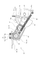
- FIG. 2 is a schematic diagram showing a cross section viewed from the position indicated by arrows AA in FIG. It is a schematic diagram as a front view of the plug door apparatus shown in FIG. It is a schematic diagram as a top view of the plug door apparatus shown in FIG. It is a schematic diagram which expands and shows the upper part of the door in FIG. It is a figure which shows typically the cross-sectional structure of the center part in the front-back direction of the vehicle of the door drive mechanism in the plug door apparatus shown in FIG. It is a top view of the plug mechanism in the plug door apparatus shown in FIG. FIG.
- FIG. 8 is a diagram including a partial cross section of the plug mechanism shown in FIG. 7 as viewed from a DD arrow position.
- FIG. 8 is a side view of the plug mechanism shown in FIG. 7 as viewed from the direction of arrow E. It is a rear view of the plug mechanism shown in FIG. It is a top view for demonstrating the action
- It is a schematic diagram which expands and shows the lower part of the door in FIG.
- It is a schematic diagram as a top view of the plug door apparatus shown in FIG. 3, and is a figure which also shows the position of the door where opening operation
- FIG. 17 is a schematic diagram showing a cross section viewed from the position of the arrows JJ in FIG. It is a schematic diagram as a front view of the plug door apparatus shown in FIG. It is a schematic diagram as a top view of the plug door apparatus shown in FIG. It is a figure which expands and shows a part of FIG. It is a schematic diagram which expands and shows the upper part of the door in FIG. It is a front view which shows a part of lock mechanism in the plug door apparatus shown in FIG. It is a figure which shows typically a part of lock mechanism shown in FIG. It is a figure which shows a part of lock mechanism shown in FIG.
- FIG. 18 is a figure which shows the operation state different from FIG. It is a figure which shows a part of lock mechanism shown in FIG. 18, and is a figure which shows the operation state different from FIG. It is a top view which shows a part of lock mechanism shown in FIG. It is a mimetic diagram showing the whole plug door device concerning one embodiment of the present invention. It is a schematic diagram which shows the cross section seen from the JJ line
- FIG. 34 is a rear view of the plug mechanism shown in FIG. 33, including a partial cross section seen from the direction of arrow F. It is a top view for demonstrating the action
- FIG. 40 is a front view including a partial cross section of the rotating arm mechanism shown in FIG.
- FIG. 39 is a side view of the rotation arm mechanism shown in FIG.
- FIG. 30 is a front view showing a part of a lock mechanism in the plug door device shown in FIG. 29. It is a top view which shows the rotation arm mechanism which concerns on a modification.
- the present invention can be applied as a plug door device that is installed at an entrance of a vehicle and performs an opening / closing operation of the door and a plug operation for moving the door in the width direction of the vehicle.
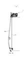
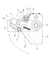
- FIG. 1 is a schematic view showing the entirety of a plug door device 1 according to a first embodiment of the present invention.
- the plug door device 1 shown in FIG. 1 can also be applied to a single-drawing door composed of one sheet.
- FIG. 1 is a schematic view seen from the inside of the vehicle, and shows a state in which the door 104 is installed with respect to the entrance 102 of the vehicle.
- FIG. 2 is a schematic diagram showing a cross section viewed from the position of the arrows AA in FIG.
- FIG. 3 is a schematic diagram as a front view of the plug door device 1, and is an enlarged view of the upper portion of the door 104 in FIG.
- FIG. 1 is a schematic view showing the entirety of a plug door device 1 according to a first embodiment of the present invention.
- the plug door device 1 shown in FIG. 1 can also be applied to a single-drawing door composed of one sheet.
- FIG. 1 is a schematic view seen from the inside of the vehicle, and shows a state in which
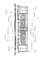
- FIG. 4 is a schematic view as a plan view of the plug door device 1 shown in FIG.
- FIG. 5 is a schematic diagram as a side view of the plug door device 1, and is an enlarged view of the upper portion of the door 104 in FIG.
- FIG. 1 illustrates a state in which the door 104 is closed, and the entrance 102 is indicated by a broken line.
- a frame 103 is fixed to the upper part of the entrance 102 so as to extend in the front-rear direction of the vehicle.
- the front-rear direction of the vehicle is a direction parallel to the traveling direction of the vehicle, and is a direction indicated by a double-ended arrow B in FIG.
- the vehicle side wall 101 and the frame 103 constitute a part of the vehicle main body.
- one door 104 is installed so as to cover the entrance 102.
- One door 104 is a one-way door and is opened and closed by the plug door device 1.
- the door 104 is formed so as to gently curve and protrude toward the outside in the width direction of the vehicle on the lower side.
- the width direction of the vehicle (hereinafter also referred to as “vehicle width direction”) is a direction perpendicular to the front-rear direction and the up-down direction of the vehicle, and is a direction indicated by a double-ended arrow C in FIG.
- the door 104 is comprised so that the entrance / exit 102 may be substantially sealed in the closed position (position shown in FIG.1 and FIG.2) which is a closed position.
- a plug door device 1 shown in FIG. 1 to FIG. 5 is installed as a device for opening / closing the door 104 and performing a plug operation for moving the door 104 in the vehicle width direction.
- the plug door device 1 is driven in the front-rear direction of the vehicle by a door drive mechanism 13 that drives the fixed base 11, the slide base 12, and the single door 104 to move in the front-rear direction of the vehicle.
- illustration of the fixed base 11 is omitted.
- the fixed base 11 is fixed to a plate-like member 103a that is a part of the frame 103 constituting the vehicle body (see FIG. 5). Thus, the fixed base 11 is fixed so as not to move relative to the vehicle body.
- the fixed base 11 includes a flat plate-like portion 11a installed horizontally and a pair of slide support portions (11b, 11b) provided on both sides of the plate-like portion 11a in the vehicle front-rear direction. Yes.
- the slide support portion 11b is provided as a member that is installed in a block shape so as to extend in the vehicle width direction.
- a rail member 11c for supporting the slide base 12 so as to be slidable in the vehicle width direction is fixed to each slide support portion 11b.
- the plate-shaped part 11a has illustrated the form comprised as two plate-shaped members each fixed with respect to the main body of a vehicle.
- the slide base 12 shown in FIGS. 3 to 5 is installed below the fixed base 11 so as to be slidable in the width direction of the vehicle with respect to the fixed base 11.
- the slide base 12 is provided with a main body portion 12a, a bracket portion 12b, and a wheel portion 12c that are installed so as to extend flat in the horizontal direction.
- the bracket portion 12b is bent downward with respect to the main body portion 12a at the end in the vehicle width direction (door 104 side) of the main body portion 12a, and further bent in the horizontal direction toward the outer side in the vehicle width direction. It is provided as an extending part.
- the bracket portion 12b is provided with a double-speed rail 16 described later.
- the wheel part 12c is installed in the both sides of the vehicle front-back direction in the main-body part 12a, and is provided with the wheel which rolls on the rail member 11c extended in the vehicle width direction.
- the slide base 12 is configured to be slidable in the vehicle width direction with respect to the fixed base 11.
- the door drive mechanism 13 shown in FIGS. 3 to 5 is installed in the main body 12a of the slide base 12, and is provided as a mechanism for moving one door 104 in the front-rear direction of the vehicle via the connecting portion 19.
- the door drive mechanism 13 is installed on the lower side of the main body 12a.
- the door drive mechanism 13 includes a drive unit 13a including a direct drive brushless electric motor 21 (see FIG. 6 described later), a drive pulley 13b, a plurality of driven pulleys 13c, a drive belt 13d, and a plurality of idler pulleys 13e. , Etc. are provided.
- the driving pulley 13b is provided as a pulley to which the driving force from the driving unit 13a is input.
- the driven pulley 13c is provided corresponding to the driving pulley 13a, and in the present embodiment, two driven pulleys 13c are provided.
- the driving pulley 13b constitutes the driving wheel member of this embodiment
- the plurality of driven pulleys 13c constitutes the driven wheel member of this embodiment
- the driving belt 13d constitutes the endless member of this embodiment.
- the drive belt 13d is a toothed belt and is wound around the outer periphery of the drive pulley 13b and the plurality of driven pulleys (13c, 13c) so as to rotate the drive pulley 13b. Accordingly, it is provided as a ring-shaped belt member that rotates the plurality of driven pulleys (13c, 13c).
- a connecting portion 19 is attached to the drive belt 13d.
- two idler pulleys 13e are provided, and are arranged between the drive pulley 13b and each driven pulley 13c at a position pressed against the drive belt 13d from the outside to the inside of the drive belt 13d. Yes.
- the drive belt 13d is wound around the outer periphery of each idler pulley 13e at a predetermined angle, and a predetermined tension is generated on the drive belt 13d.
- the drive part 13a and the drive pulley 13b are arrange
- the plurality of driven pulleys (13c, 13c) are arranged on both sides in the vehicle front-rear direction with respect to the drive pulley 13b.
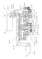
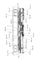
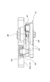
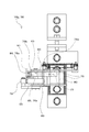
- FIG. 6 is a diagram schematically showing a cross-sectional structure of the central portion of the door drive mechanism 13 in the front-rear direction of the vehicle, and shows a cross-sectional structure of a plane perpendicular to the front-rear direction of the vehicle.
- FIG. 6 is illustrated in a simplified state with some components omitted, and hatching indicating a cross-sectional state is also omitted from the viewpoint of clearly showing the illustrated components.
- the outer shape of the lock mechanism 17 described later is also shown.
- the drive unit 13 a is a planetary gear to which a driving force from the brushless electric motor 21 is input in addition to the brassless electric motor 21 that is provided as a driving source and constitutes the electric motor of the present embodiment.
- a mechanism 20 is provided.
- the planetary gear mechanism 20 includes a sun gear 20a, a plurality of planetary gears 20b, a carrier 20c, a ring gear 20d, and the like.
- the driving force from the brushless electric motor 21 is input to the sun gear 20a.
- the plurality of planetary gears 20b are arranged around the sun gear 20a, and are provided so as to mesh with the sun gear 20a and revolve around the sun gear 20a while rotating.
- the carrier 20c is provided as a frame member that rotatably supports each of the plurality of planetary gears 20b and supports the planetary gears 20b so as to revolve.
- the ring gear 20d is provided as a ring-shaped gear in which inner teeth that mesh with the planetary gears 20b are formed on the inner periphery.
- ring gear 20d a ring-shaped portion in which inner teeth meshing with each planetary gear 20b are formed integrally with the drive pulley 13b inside the cylindrical drive pulley 13b. .
- the number of parts is reduced.
- the door drive mechanism 13 can be reduced in size because the sun gear 20a, the planetary gear 20b, and the ring gear 20d in the planetary gear mechanism 20 are disposed inside the drive pulley 13b. For this reason, the further miniaturization as the plug door apparatus 1 will be achieved.
- the lock output unit 22 is provided as a mechanism for inputting a driving force output from the carrier 20c to the lock mechanism 17 described later when the carrier 20c swings about the axis of the sun gear 20a.
- the lock output unit 22 is configured to convert the direction in which the driving force is output with respect to the driving force output by the swing of the carrier 20c, and to output the driving force in a linear direction parallel to the longitudinal direction of the vehicle.
- an output roller 22 a is provided at a tip portion that outputs the driving force in the lock output unit 22. The driving force of the carrier 20c is input to the lock mechanism 17 described later via the output roller 22a.
- the driving force from the direct drive brushless electric motor 21 is input to the sun gear 20a, and the driving force output from the ring gear 20d is input to the driving pulley 13b and output from the carrier 20c.
- the driving force is input to the lock mechanism 17 as an example.
- the driving force from the brushless electric motor 21 is input to any one of the sun gear 20a, the carrier 20c, and the ring gear 20d, and the driving force that is output from any one of the sun gear 20a, the carrier 20c, and the ring gear 20d. May be input to the driving pulley 20b and the driving force output from the remaining one of the sun gear 20a, the carrier 20c, and the ring gear 20d may be input to the lock mechanism 17.
- the connecting portion 19 that is attached to the driving belt 13d and transmits the driving force from the door driving mechanism 13 is constituted by a bent plate-like member. And the edge part of the connection part 19 of these driven pulleys (13c, 13c) in the side wound by the drive belt 13d around the two driven pulleys (13c, 13c) without passing through the drive pulley 13b. It is fixed at the position between.
- connection portion 19 is configured to once extend downward from a portion fixed to the drive belt 13d, then bend and extend horizontally toward the door 104 side, and further bend and extend upward. And the connection part 19 is being fixed to the support rail 16d in the double speed rail 16 mentioned later by the edge part of the part extended upwards.
- the connecting portion 19 is provided with a protruding end portion 19a that is partially bent from the end portion of the portion extending upward and extends horizontally to protrude.
- the protruding end portion 19a is provided with a shaft portion 14 protruding in a cantilever manner so as to extend upward.
- the shaft portion 14 is provided with a shaft roller 14a that is rotatably attached to a shaft main body fixed to the protruding end portion 19a of the shaft portion 14.
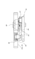
- the double speed rail 16 includes two facing racks (16a, 16b), a pinion 16c, and a support rail 16d.
- the two racks (16a, 16b) facing each other are composed of an upper rack 16a disposed on the upper side and a lower rack 16b disposed on the lower side.
- the upper rack 16a and the lower rack 16b are disposed so as to extend in parallel with each other in the front-rear direction of the vehicle.
- the pinion 16c is disposed between the two racks (16a, 16b) and is disposed so as to mesh with the teeth provided in each rack (16a, 16b).
- the pinion 16c is rotatably supported by the support rail 16d.
- the pinion 16c is connected with the connection part 19 side. That is, the pinion 16c is connected to the connecting portion 19 via the support rail 16d.
- the connecting portion 19 fixed to the drive belt 13d, the support rail 16d, and the pinion 16c are connected to each other so that the relative position does not change.
- the support rail 16d that rotatably supports the pinion 16c is configured to support the upper rack 16a and the lower rack 16b in a state of being sandwiched from both sides in the vehicle width direction.
- the support rail 16c supports the upper rack 16a and the lower rack 16b so as to be slidable in the front-rear direction of the vehicle.
- one lower rack 16b of the two racks (16a, 16b) is fixed and connected to the bracket portion 12b of the slide base 12, and the other upper rack 16a is connected to the door 104 side. It is connected.
- the upper rack 16a is connected to the door 104 via a door support member 104a.
- the door support member 104a supports the door 104 in a suspended state.
- the double-speed rail 16 is configured as described above, when the drive pulley 13d of the door drive mechanism 13 is driven, the support rail 16d and the pinion 16c are connected to the front and rear of the vehicle together with the connecting portion 19 fixed to the drive belt 13d. Move in the direction. As a result, the pinion 16c is engaged with the lower rack 16b fixed to the slide base 12 and moves to one side in the front-rear direction of the vehicle. And with respect to this moving pinion 16c, the upper rail 16a meshing with the pinion 16c moves in the same direction in the longitudinal direction of the vehicle. For this reason, the upper rack 16a moves with respect to the lower rack 16b at a speed twice that of the movement speed of the pinion 16c.
- the amount of movement of the upper rack 16a relative to the lower rack 16b is twice the amount of movement in the same direction as the amount of movement of the pinion 16c relative to the lower rack 16b.
- the door 104 connected to the upper rack 16a via the door support member 104a also moves at the same speed as the upper rack 16a. And the door 104 will move to the front-back direction of a vehicle with respect to the slide base 12 with which the lower rack 16b is connected.
- a plug mechanism for performing a plug operation for moving the door 104 in the vehicle width direction includes a shaft portion 14, a guide portion 15, and a roller guide 23.
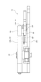
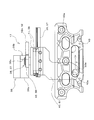
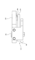
- FIG. 7 is a plan view showing the plug mechanism.
- FIG. 8 is a view including a partial cross section of the plug mechanism as seen from the position of arrows DD in FIG.
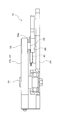
- FIG. 9 is a side view of the plug mechanism, as viewed from the direction of arrow E in FIG.
- FIG. 10 is a rear view of the plug mechanism and includes a partial cross section viewed from the direction of arrow F in FIG.
- FIG. 11 is a plan view for explaining the operation of the plug mechanism. 8 to 10 are enlarged from FIGS. 7 and 11. 8 to 10 show a state of the plug mechanism when the door 104 is in the closed position. On the other hand, FIG. 11 shows a state immediately after the plug operation is completed when the door 104 is opened from the closed position.
- 3 to 5 and 7 to 10 are arranged between the fixed base 11 and the slide base 12 (the shaft portion 14, the guide portion 15, and the roller guide 23).
- the shaft portion 14 is provided at the protruding end portion 19a of the connecting portion 19.
- the roller guide 23 is fixed to the lower surface side of the plate-like portion 11 a of the fixed base 11.
- the guide portion 15 includes a first link 24 and a second link 25 and is installed below the fixed base 11.
- the guide portion 15 is rotatably installed on the fixed base 11 at the first link 24.
- the first link 24 is a substantially rectangular plate-like member, and is provided such that one end side thereof is rotatable with respect to the fixed base 11. Specifically, the first link 24 is provided so as to be rotatable around a first rotation shaft 26 that faces a substantially vertical direction. In addition, a first cutout portion 24 a that can accommodate the shaft roller 14 a of the shaft portion 14 is formed on the peripheral edge on the other end side of the first link 24.
- the second link 25 is a plate-like member and is rotatably provided on the first link 24. Specifically, the second link 25 is rotatably provided around a second rotation shaft 27 that faces the substantially vertical direction provided in the vicinity of the first notch 24 a of the first link 24. Further, a second cutout portion 25 a that can accommodate the shaft roller 14 a of the shaft portion 14 is formed on the periphery of the second link 25. Further, the second link 25 is provided with a guide roller 28 that is rotatably attached around the vertical axis. The guide roller 28 is rotatably attached to a rotary shaft 29 that protrudes upward from the second link 25, and is disposed at substantially the same height as the roller guide 23 fixed to the fixed base 11.
- the first notch portion 24 a of the first link 24 and the second notch portion 25 a of the second link 25 are axially viewed from above.
- the periphery of the portion 14 is surrounded.
- the first link 24 is held so that the opening side of the first cutout portion 24a faces outward in the vehicle width direction
- the second link 25 holds the opening side of the second cutout portion 25a.
- the first rotation shaft 26 is held so as to face in the opposite direction. Accordingly, the second link 25 restrains the shaft portion 14 from moving from the inside of the first cutout portion 24 a toward the outside in the first link 24.
- the guide roller 28 of the second link 25 is located on the outer side in the vehicle width direction with respect to the second notch 25a. And the 2nd rotating shaft 27 of the 2nd link 25 is located in the vehicle width direction inner side rather than the 2nd notch part 25a.
- a helical spring 30 as an urging means is provided between the first link 24 and the second link 25.
- One end of the helical spring 30 is provided at a substantially intermediate portion between the second rotation shaft 27 and the guide roller 28 in the second link 25, and the other end is the first rotation shaft 26 in the first link 24. It is provided in the position near. Accordingly, the second link 25 is attached to the helical spring 30 so as to rotate in a direction in which the restraint of the shaft portion 14 is released (a clockwise direction around the second rotation shaft 27 when viewed from above). Be forced. That is, the second link 25 is urged by the helical spring 30 in the direction in which the guide roller 28 approaches the roller guide 23.
- the roller guide 23 is provided as a plate-like member.
- the roller guide 23 is provided with a slope 23a for guiding the guide roller 28 and a curved surface 23b for guiding the guide roller 28 continuously to the slope 23a.
- the inclined surface 23a is provided as a part of the side surface of the roller guide 23, and is located more outward in the vehicle width direction as it goes in a direction in which the door 104 opens (hereinafter referred to as an opening direction, indicated by an arrow G1 in FIG. 7). It is comprised as a flat surface formed in this way.
- the curved surface 23b is provided as a part of the side surface of the roller guide 23.
- the curved surface 23b is continuous from the inclined surface 23a, bends so as to protrude in a substantially semicircular arc shape, and further bends so as to be recessed in a substantially semicircular arc shape. It is configured as an extended curved surface.
- the curved surface 23b is convex in the opening direction at a position close to the outside in the vehicle width direction, and closes in the direction close to the inside in the vehicle width direction (the direction opposite to the opening direction, which is the following). , Which is indicated as an arrow G2 in FIG.
- FIG. 12 is a schematic diagram showing the lower portion of the door 104 in FIG. 2 in an enlarged manner.
- the upper and lower portions of the entrance / exit 102 are provided with rotating arms 18 (18 a, 18 b) that rotate to guide the door 104 in the vehicle width direction. ing.
- An upper turning arm 18 a is provided at the upper part of the entrance 102 and a lower turning arm 18 b is provided at the lower part of the entrance 102.
- the upper turning arm 18a is fixed to the upper end side of the connecting shaft 31 extending substantially in the vertical direction, and is installed so as to protrude from the connecting shaft 31 in a cantilevered manner in the horizontal direction. Further, the connecting shaft 31 is rotatably attached to a bracket extending from an edge portion of the entrance 102 on the vehicle side wall 101 at both upper and lower ends.
- an upper roller 32 is provided at the tip of the upper turning arm 18a so as to be rotatable around a rotation shaft extending substantially vertically upward.
- the main body 12a of the slide base 12 is provided with a long hole 33 that extends in the front-rear direction of the vehicle (see FIG. 4). The upper roller 32 is inserted into the long hole 33 from below and is disposed so as to be relatively movable along the long hole 33.
- the lower rotating arm 18b is fixed to the lower side of the connecting shaft 31 and is installed so as to protrude from the connecting shaft 31 in a cantilevered manner in the horizontal direction. For this reason, the lower rotation arm 18b is configured to rotate together with the connecting shaft 31 as the upper rotation arm 18a rotates. Further, a lower roller 34 is provided at the tip of the lower rotation arm 18b so as to be rotatable around a rotation axis extending substantially vertically upward. And the door rail 35 extended in the front-back direction of a vehicle is provided in the lower end side in the vehicle width direction of the door 104. As shown in FIG. The door rail 35 is formed with a groove that opens downward and extends in the front-rear direction of the vehicle. The lower roller 34 is inserted into the groove of the door rail 35 from below, and is configured to be relatively movable along the door rail 35 (see FIG. 12).
- FIG. 13 is a front view of the lock mechanism 17.
- FIG. 14 is a plan view of the lock mechanism 17.
- the lock mechanism 17 shown in FIGS. 3 to 6, 13, and 14 is provided as a lockable mechanism so as to limit the movement of the door 104 in the closed position of the door 104.
- the lock mechanism 17 includes a lock fixing part 36 and a lock moving part 37.
- the lock fixing part 36 is configured as a block-like member provided to be fixed to the fixed base 11.
- illustration of the fixed base 11 is abbreviate
- the lock fixing portion 36 is provided as a block-shaped member, but this need not be the case, and the lock fixing portion 36 is fixed to the fixed base 11 as a plate-shaped member, a pin-shaped member, or the like. It may be provided.
- the lock moving unit 37 is provided to be movable by a driving force output from the carrier 20c of the planetary gear mechanism 20 to the lock mechanism 17.
- the lock moving portion 37 is configured to abut against the lock fixing portion 36 on the inner side in the width direction of the vehicle when the door 104 is closed.
- the lock mechanism 17 is provided so as to regulate the outward movement of the door 104 in the vehicle width direction when the door 104 is closed by the lock moving portion 37 coming into contact with the lock fixing portion 36. Yes.
- the lock moving unit 37 includes a slide abutting portion 38 that can abut on the lock fixing portion 36, a slide rail 39, and a transmission member 40.
- the slide rail 39 is provided as a rail member that is fixed to the slide base 12 and extends in the front-rear direction of the vehicle.
- the slide rail 39 is configured to restrict the slide movement direction of the slide contact portion 38 to a direction parallel to the front-rear direction of the vehicle.
- the transmission member 40 is provided as a plate-like member and is disposed so as to extend in the vertical direction.
- the transmission member 40 is provided as a member that transmits the driving force output from the carrier 20 c of the planetary gear mechanism 20 to the lock mechanism 17 to the slide contact portion 38.
- the transmission member 40 is provided with a notch 40a on the lower end side, and the output roller 22a of the lock output portion 22 is fitted in the notch 40a. Has been. Further, the upper end side of the transmission member 40 is connected to the slide contact portion 38.
- the lock mechanism 17 is configured such that the driving force output from the carrier 20c via the lock output unit 22 is input to the transmission member 40.
- the transmission member 40 moves in the front-rear direction of the vehicle.
- the slide contact portion 38 whose slide movement direction is regulated by the slide rail 39 moves in the front-rear direction of the vehicle.
- the output roller 22 a has a tip portion disposed inside a long hole 43 a formed in the guide plate 43. And the output roller 22a is arrange
- the guide plate 43 is provided as a plate-like member fixed to the housing of the drive unit 13a installed on the slide base 12.
- the slide contact portion 38 includes a slide block 41 and a roller 42.
- the slide block 41 is provided in a block shape, and is provided as a member whose slide movement direction is regulated by the slide rail 39 in the vehicle front-rear direction.
- the slide block 41 is configured by being fixed so that a plurality of members are integrated. Then, the upper end side of the transmission member 40 is fixed to one of the integrated members, and the other member of the integrated members slides on the rail surface of the slide rail 39 so as to be slidable. Grooves are formed.
- the roller 42 is supported by the slide block 41 so as to be rotatable around the vertical axis. And the roller 42 is arrange
- the lock fixing portion 36 is provided as a member having a shape in which two orthogonal block-like portions are integrated, as well shown in FIGS. 6, 13, and 14.
- the side surface of the lock fixing portion 36 is provided with a first surface 36a, a second surface 36b, and an inclined surface 36c with which the roller 42 can contact.
- the first surface 36 a is provided as a side surface facing the inner side in the vehicle width direction in the lock fixing portion 36.
- the first surface 36a is formed as a surface orthogonal to the vehicle width direction, and comes into contact with the outer periphery of the roller 42 in the slide contact portion 38 of the lock moving portion 37 when the door 104 is closed. It is comprised so that the movement to the outer side in the vehicle width direction of 104 may be controlled.
- the second surface 36b is provided as a side surface facing the opening direction side in the front-rear direction of the vehicle in the lock fixing portion 36. And this 2nd surface 36b is formed as a surface which can contact
- the inclined surface 36c is provided between the first surface 36a and the second surface 36b in the lock fixing portion 36 and is provided as a side surface continuous with the first surface 36a and the second surface 36b.
- the inclined surface 36c is formed as a surface that is perpendicular to the horizontal direction, and is provided as a surface that is inclined with respect to both the first surface 36a and the second surface 36b.
- the roller 42 is disposed so as to be able to come into contact with the lock fixing portion 36 on the first surface 36a and the second surface 36b.
- the inclined surface 36c is provided so that the first surface orthogonal to each other is provided. The movement of the roller 42 between 36a and the 2nd surface 36b is comprised smoothly.
- the roller 42 that has been in contact with the first surface 36a moves to a position where it deviates from the first surface 36a.
- the position of the roller 42 that has moved to the position deviated from the first surface 36a is shown as a two-dot chain line roller 42a.
- the brushless electric motor 21 of the door drive mechanism 13 is continuously driven.
- the driving force output to the driving pulley 13b via the ring gear 20d is further transmitted to the shaft portion 14 via the driving belt 13d and the connecting portion 19.
- the shaft portion 14 urges the second link 25 in the same direction in an attempt to move in the opening direction.
- the rotation of the second link 25 relative to the first link 24 (rotation in the clockwise direction around the second rotation shaft 27 when viewed from above)
- the roller 28 is regulated at a position where the roller 28 contacts the inclined surface 23 a of the roller guide 23. Therefore, the second link 25 hardly rotates with respect to the first link 24, and the second link 25 is rotated to the first link 24 via the second rotation shaft 27 (rotating power about the first rotation shaft 26 (upward). (Turning power in the clockwise direction when viewed from the side).
- the guide roller 28 moves along the slope 23a, and the first link 24 rotates about the first rotation shaft 26 in the direction indicated by the arrow H in the figure.
- the guide roller 28 of the second link 25 moves along the inclined surface 23a of the roller guide 23 while the first link 24 rotates clockwise as viewed from above. At this time, since the second hook link 25 is attracted to the inclined surface 23a side by the helical spring 30, the guide roller 28 is not separated from the inclined surface 23a. Further, when the guide roller 28 is moving along the inclined surface 23 a, the first cutout portion 24 a of the first link 24 and the second cutout portion 25 a of the second link 25 travel around the shaft portion 14. The enclosed state is maintained.
- the guide portion 15 rotates while contacting the shaft portion 14 so that the shaft portion 14 moves in one of the vehicle width directions (opening direction). It is configured as a guiding mechanism.
- the first link 24 is arranged so that the first cutout portion 24a is located on the outer side in the vehicle width direction with respect to the position of the first rotation shaft 26 when the door 104 is in the closed position. ing.
- the guide roller 28 is positioned on the outer side in the vehicle width direction from the center of the shaft portion 14, and the second rotating shaft 27 is in the vehicle width direction from the center of the shaft portion 14.
- the 2nd link 25 is arrange
- the guide portion 15 is configured so that the urging force from the shaft portion 14 can be efficiently used for turning the first link 24.
- the door drive mechanism 13 and the slide base 12 are guided by the slide support portion 11b in the fixed base 11 and moved outward in the vehicle width direction. As a result, a plug operation in which the door 104 moves outward in the vehicle width direction is performed. Then, when the plug operation is performed, the door 104 can be moved in the opening direction.
- the lock output unit 22 connected to the carrier 20c of the planetary gear mechanism 20 has a biasing means such as a spring for biasing the output roller 22a in the direction opposite to the direction indicated by the two-dot chain line arrow I in FIG. (Not shown) is provided.
- a biasing means such as a spring for biasing the output roller 22a in the direction opposite to the direction indicated by the two-dot chain line arrow I in FIG. (Not shown) is provided.
- the drive belt 13d is driven, and the support rail 16d and the pinion 16c in the double speed rail 16 move together with the connecting portion 19. Therefore, the upper rack 16a connected to the door 104 moves at a double speed relative to the pinion 16c with respect to the lower rack 16b fixed to the slide base 12. Thereby, the door 104 moves in the opening direction, and the opening operation of the door 104 is performed. During the movement of the door 104 in the opening direction, the shaft portion 14 does not receive a force in the vehicle width direction from the guide portion 15 and moves linearly in the opening direction together with the connecting portion 19.
- FIG. 15 is a schematic diagram as a plan view of the plug door device 1 shown in FIG. 3, and also shows the position of the door 104 where the opening operation has been performed. When the opening operation of the door 104 is completed, the door 104 moves to a position indicated by a two-dot chain line in FIG.
- the helical spring 30 acts on the second link 25 in the clockwise direction as viewed from above. That is, a pulling force is applied to the second link 25 from the helical spring 30 so that the guide roller 28 is located at a position in contact with the curved surface 23 b of the roller guide 23.
- the guide roller 28 is fitted in a recess having a semicircular arc shape that is substantially the same as the outer peripheral shape of the guide roller 28 on the curved surface 23b. Accordingly, the first link 24 and the second link 25 are stably held at predetermined positions.
- the second link 25 is held at a position where the shaft portion 14 that has linearly moved in the closing direction can come into contact with the inner edge of the second cutout portion 25a.
- the 1st link 24 is also hold
- the shaft portion 14 abuts against the inner edge of the second cutout portion 25a of the second link 25 when the door 104 moves a predetermined amount in the closing direction from the fully open position (see FIG. 11).
- the two links 25 are energized.
- the second link 25 rotates counterclockwise when viewed from above about the second rotation shaft 27 against the force of the helical spring 30, so that the shaft portion 14 moves in the closing direction. Linear movement is not hindered.
- the guide roller 28 moves along the curved surface 23 b of the roller guide 23. It should be noted that when the second link 25 is rotated, the first link 24 is held at a predetermined position or in the vicinity thereof with almost no rotation.
- the shaft portion 14 moves in the closing direction to a position where it contacts the inner edge of the first notch portion 24a of the first link 24, and biases the first link 24 in the closing direction.
- the first link 24 rotates counterclockwise as viewed from above about the first rotation shaft 26, and the shaft portion 14 is guided inward in the vehicle width direction.
- the door 104 moves in the same manner as the shaft portion 14. That is, the door 104 moves linearly in the closing direction from the fully open position, and is drawn inward in the vehicle width direction in the vicinity of the closing position and moves to the closing position. Thereby, the plug operation to the inside in the vehicle width direction by the plug mechanism is completed.
- the guide portion 15 rotates while contacting the shaft portion 14 so that the shaft portion 14 moves to the other side (the closing direction) in the width direction of the vehicle. It is comprised as a mechanism which guides.
- the roller 42 moves from the position shown as the two-dot chain line roller 42a in FIG. Thereby, the locked state of the door 104 by the lock mechanism 17 is ensured, and the plug operation to the outside in the vehicle width direction by the plug mechanism cannot be performed.
- the guide portion 15 abuts on the shaft portion 14 and rotates to guide the shaft portion 14 in the vehicle width direction. Therefore, the operation of the guide portion 15 is an operation that follows the movement of the door 104 in the vehicle width direction. Thereby, according to the movement state of the door 104 in the vehicle width direction, the space occupied by the guide portion 15 in the vehicle width direction can be further reduced. Thereby, the small plug door apparatus 1 which can perform an opening / closing operation
- the door drive mechanism 13 moves the door 104 in the longitudinal direction of the vehicle via the double speed rail 16 constituted by two racks (16a, 16b) and a pinion 16c, the operation stroke of the door drive mechanism 13 is doubled.
- the door 104 can be moved efficiently. For this reason, a further compact plug door device 1 can be realized in the longitudinal direction of the vehicle.
- one door drive mechanism 13 that is installed on the slide base 12 and moves one door 104 in the front-rear direction of the vehicle via the connecting portion 19 and the double speed rail 16 is a direct drive type.
- Endless member driving belt
- the driving pulley 13b to which the driving force from the driving portion 13a is input the driven pulley 13c, and the driving pulley 13b. 13d.
- the drive pulley 13b and the driven pulley 13c do not move during the operation of the door drive mechanism 13.
- a part of the door drive mechanism 13 includes a door 104.
- a door 104 There is no significant protrusion with respect to the installed entrance 102. Therefore, the restriction of the installation space is greatly suppressed, and it can be easily applied to the one-way door 104.
- the present embodiment it is possible to realize a small plug door device 1 that can perform an opening / closing operation and a plug operation by the door drive mechanism 13 that applies a force in the front-rear direction of the vehicle to the door 104.
- the plug door device 1 that can be applied to the single door 104 can be provided.
- the drive unit 13 a includes the direct drive type brushless electric motor 21 and the planetary gear mechanism 20. Then, in the sun gear 20a, the carrier 20c, and the ring gear 20d of the planetary gear mechanism 20, the driving force of the brushless electric motor 21 is input to one of them, and the driving force from the other one is output to the driving pulley 13b and remains. The driving force from one is output to the lock mechanism 17. For this reason, the door 104 can be opened / closed, plugged, and the door 104 can be locked by the locking mechanism 17 by a single direct-drive brushless electric motor 21, thereby realizing a compact and efficient drive unit 13 a. can do.
- the lock moving portion 37 contacts the lock fixing portion 36 fixed to the fixed base 11 side on the inner side in the vehicle width direction, so that the door 104 moves outward in the vehicle width direction when closed. Movement is restricted. For this reason, when the door 104 is closed, the door 104 is restrained so that it does not move more reliably and does not move outward in the vehicle width direction. Therefore, the door 104 can be locked without rattling when closed.
- the present embodiment it is possible to realize a small plug door device 1 that can perform an opening / closing operation and a plug operation by the door drive mechanism 13 that applies a force in the front-rear direction of the vehicle to the door 104. It is possible to provide a plug door device 1 that can lock the door 104 without rattling when closed.
- the driving force from the planetary gear mechanism 20 is transmitted to the slide contact portion 38 via the transmission member 40, so that the slide contact portion 38 performs a predetermined restriction on the slide rail 39. It slides along the formed direction and comes into contact with the lock fixing portion 36. For this reason, since the slide contact part 38 moves smoothly on the slide rail 39 by the driving force from the planetary gear mechanism 20, the necessity of setting the strength of the planetary gear mechanism 20 high can be suppressed. Thereby, the planetary gear mechanism 20 can be configured more compactly.
- the slide contact portion 38 can move on the slide rail 39 by the slide block 41 while contacting the lock fixing portion 36 by the rotatable roller 42. For this reason, it is suppressed that the frictional force with the lock fixing part 36 prevents the movement of the slide contact part 38 on the slide rail 39, and the slide contact part 38 can move smoothly on the slide rail 39. it can.
- the lock moving portion 37 comes into contact with the first surface 36 a of the lock fixing portion 36 and the door 104 is locked.
- the lock moving portion 37 and the second surface 36b of the lock fixing portion 36 come into contact with each other, and the force acting between the two is balanced, and the planetary gear mechanism 20 moves to the lock mechanism 17.
- the output of is fixed.
- the driving pulley 13b, the driven pulley 13c, and the endless member (driving belt) 13d are actuated by the driving force input from the planetary gear mechanism 20 to the driving pulley 13b, and the door 104 is opened and closed.
- the drive force is distributed from the planetary gear mechanism 20 to the drive pulley 13b and the lock mechanism 17 by the lock fixing portion 36 provided with the first surface 36a and the second surface 36b orthogonal to each other. Therefore, a configuration in which the driving force is efficiently distributed to the drive pulley 13b and the lock mechanism 17 can be realized by a simple mechanism in which the lock fixing portion 36 is provided with the first surface 36a and the second surface 36b.
- the drive part 13a which outputs a driving force with respect to the lock mechanism 17 will be arrange
- a plurality of driven pulleys (13c, 13c) are arranged on both sides in the vehicle front-rear direction with respect to the drive pulley 13b arranged in the central portion of the door 104, an endless member (drive belt) that circulates them is provided. ) 13d can be placed over a longer circuit distance in a compact area. For this reason, the circumference distance of the endless member 13d can be ensured efficiently.
- the one door drive mechanism 13 that is installed on the slide base 12 and moves the one door 104 in the front-rear direction of the vehicle via the connecting portion 19 and the double speed rail 16 is provided with the brushless electric motor 21.
- a drive pulley 13b Including a drive pulley 13b, a drive pulley 13b to which a drive force from the drive unit 13a is input, a driven pulley 13c, and a drive belt 13d that rotates the driven pulley 13c as the drive pulley 13b rotates.
- the drive pulley 13b and the driven pulley 13c do not move during the operation of the door drive mechanism 13.
- a part of door drive mechanism 13 does not protrude greatly with respect to the entrance 102 where the door 104 is installed. Therefore, the restriction of the installation space is greatly suppressed, and it can be easily applied to the one-way door 104.
- the drive unit 13 a includes the direct drive type brushless electric motor 21 and the planetary gear mechanism 20. Then, in the sun gear 20a, the carrier 20c, and the ring gear 20d of the planetary gear mechanism 20, the driving force of the brushless electric motor 21 is input to one of them, and the driving force from the other one is output to the driving pulley 13b and remains. The driving force from one is output to the lock mechanism 17. Therefore, the single drive-less brushless electric motor 21 can perform the opening / closing operation of the door 104, the plug operation, and the locking operation of the door 104 by the lock mechanism, thereby realizing a compact and efficient drive unit 13a. be able to.
- FIG. 16 is a schematic view showing the entirety of the plug door device 2 according to the second embodiment of the present invention.
- the plug door device 2 shown in FIG. 16 is suitable for a double-drawing draw door composed of two sheets.
- FIG. 16 is a schematic view seen from the inside of the vehicle, and shows a state in which the door (108, 109) is installed with respect to the entrance 106 of the vehicle.
- FIG. 17 is a schematic diagram showing a cross section viewed from the position of the arrows JJ in FIG.
- FIG. 18 is a schematic diagram as a front view of the plug door device 2 and is an enlarged view of an upper portion of the door 108 in FIG.
- FIG. 16 and 18 the illustration of a cover disposed inside the vehicle when the plug door device 2 is stored in the vehicle at the upper part of the entrance 106 is omitted.
- FIG. 19 is a schematic diagram as a plan view of the plug door device 2 shown in FIG. 18, and is shown together with the doors (108, 109).
- FIG. 20 is an enlarged view of a part of FIG.
- FIG. 21 is a schematic diagram as a side view of the plug door device 2 and is an enlarged view of the upper portion of the door (108, 109) in FIG.
- FIG. 16 illustrates a state in which the doors (108, 109) are closed, and the entrance / exit 106 is indicated by a broken line.
- a frame 107 is fixed to the upper part of the entrance 106 so as to extend in the front-rear direction of the vehicle.
- the front-rear direction of the vehicle is a direction parallel to the traveling direction of the vehicle, as in the first embodiment, and is a direction indicated by a double-ended arrow B in FIG.
- the vehicle side wall 105 and the frame 107 constitute a part of the vehicle main body.
- the two doors (108, 109) are installed so as to cover the entrance 106.
- the two doors (108, 109) are double-drawing doors that are opened and closed by the plug door device 2.
- the door (108,109) is formed in the downward side so that it may curve gently and protrude toward the outer side of the width direction of a vehicle (refer FIG. 17).
- the width direction of the vehicle (hereinafter also referred to as “vehicle width direction”) is a direction perpendicular to the front-rear direction and the up-down direction of the vehicle, as in the first embodiment. This is the direction indicated by arrow C.
- the doors (108, 109) are configured to substantially seal the entrance / exit 106 at a closed position (a position shown in FIGS. 16 and 17), which is a closed position.
- the plug door device 2 shown in FIGS. 16 to 21 is installed at the entrance / exit 106 of the vehicle, and performs an opening / closing operation of the doors (108, 109) and a plug operation of moving the doors (108, 109) in the vehicle width direction. It is provided as a device.
- the plug door device 2 includes a door drive mechanism 53 that drives the fixed base 51, the slide base 52, and the two draw doors (108, 109) to move in the front-rear direction of the vehicle.
- the arm 58 (58a, 58b) is provided.
- the fixed base 51 is fixed to a bracket 107a which is a part of the frame 107 constituting the vehicle body.
- the fixed base 51 is fixed so as not to move relative to the vehicle body.
- the fixed base 51 is provided with a flat plate-like portion 51a installed horizontally and a pair of slide support portions (51b, 51b) provided on both sides of the plate-like portion 51a in the vehicle front-rear direction.
- the slide support portion 51b is provided as a member that is installed in a block shape so as to extend in the vehicle width direction.
- a rail member 51c for supporting the slide base 52 so as to be slidable in the vehicle width direction is fixed to each slide support portion 51b.
- the slide base 52 shown in FIGS. 18 and 21 is installed below the fixed base 51 so as to be slidable in the vehicle width direction with respect to the fixed base 51.
- the slide base 52 is provided with a main body portion 52a, a bracket portion 52b, and a wheel portion 52c that are installed so as to extend flat in the horizontal direction.
- the bracket portion 52b bends downward with respect to the main body portion 52a at the outer end in the vehicle width direction (doors 108 and 109 side) of the main body portion 52a, and further bends outward in the vehicle width direction in the horizontal direction. It is provided as an extending part. And the bracket part 52a is provided with two or more, and it is provided so that it may extend from the several places in the front-back direction of a vehicle with respect to the main-body part 52a.
- a double speed rail 56 (56a, 56b), which will be described later, is installed in each bracket portion 52b.
- the wheel part 52c is installed in the both sides of the vehicle front-back direction in the main-body part 52a, and is provided with the wheel which rolls on the rail member 51c extended in the vehicle width direction.
- the slide base 52 is configured to be slidable in the vehicle width direction with respect to the fixed base 51.
- the door drive mechanism 53 shown in FIGS. 18 to 21 is installed in the main body 52a of the slide base 52, and is provided as a mechanism for moving the two doors (108, 109) in the longitudinal direction of the vehicle via the connecting portion 59. It has been.
- the door drive mechanism 53 is installed on the lower side of the main body 52a.
- the door drive mechanism 53 is a direct drive brushless electric motor 21 configured in the same manner as the brushless electric motor 21 of the first embodiment (see FIG. 6 of the first embodiment.
- the drive unit 53a, the rack and pinion mechanism 53b, and the like are included.
- the rack and pinion mechanism 53b is provided as a mechanism that moves the connecting portion 59 when the driving force from the driving portion 53a is input.
- the rack and pinion mechanism 53b includes two drive racks 60 (60a and 60b) facing each other and a drive pinion 61.
- the two drive racks 60 (60a, 60b) facing each other are configured by an outer drive rack 60a disposed on the outer side in the vehicle width direction and an inner drive rack 60b disposed on the inner side in the vehicle width direction.
- the outer drive rack 60a and the inner drive rack 60b are arranged so as to extend in parallel with each other in the vehicle front-rear direction.
- the drive pinion 61 is disposed between the two drive racks (60a, 60b), and is disposed so as to mesh with teeth provided on opposite sides of each drive rack (60a, 60b). And this drive pinion 61 is arrange
- the drive pinion 61 is fixed concentrically to the ring gear 20d of the planetary gear mechanism 20 in the drive unit 53a. For this reason, it is comprised so that it may rotate centering on the same rotating shaft center with rotation of the ring gear 20d.
- the drive pinion 61 rotates together with the ring gear 20d, the two drive racks (60a, 60b) meshing with the drive pinion 61 move in opposite directions in the vehicle front-rear direction.
- the drive unit 53a and the drive pinion 61 in the rack and pinion mechanism 53b are disposed in the center portion of the slide base 52 in the front-rear direction of the vehicle.
- the connection part 59 is attached to the drive rack 60 (60a, 60b) in the rack and pinion mechanism 53b.
- the drive unit 53a is configured similarly to the drive unit 13a of the first embodiment. That is, the drive unit 53a includes a planetary gear mechanism 20 to which a driving force from the brushless electric motor 21 is input in addition to the brassless electric motor 21 provided as a driving source and constituting the electric motor of the present embodiment. It is configured. Similar to the first embodiment, the planetary gear mechanism 20 includes a sun gear 20a, a plurality of planetary gears 20b, a carrier 20c, a ring gear 20d, and the like.
- the sun gear 20a, the planetary gear 20b, the carrier 20c, and the ring gear 20d are configured in the same manner as in the first embodiment. That is, a driving force from the brushless electric motor 21 is input to the sun gear 20a, a plurality of planetary gears 20b are arranged to revolve around the sun gear 20a, and a carrier member 20c supports the planetary gear 20b so as to revolve freely. It is provided as.
- the ring gear 20d is provided as a ring-shaped gear in which inner teeth that mesh with the planetary gears 20b are formed on the inner periphery. As described above, the drive pinion 61 in the rack and pinion mechanism 13b is fixed to the ring gear 20d.
- the lock output unit 22 is provided as a mechanism for inputting the driving force output from the carrier 20 c to the lock mechanism 57 when the carrier 20 c swings about the axis of the sun gear 20 a.
- the lock output unit 22 is configured to convert the direction in which the driving force is output with respect to the driving force output by the swing of the carrier 20c, and to output the driving force in a linear direction parallel to the longitudinal direction of the vehicle.
- an output roller 22 a is provided at a tip portion that outputs the driving force in the lock output unit 22.
- the lock output portion 22 is provided with an output roller shaft 22 b that rotatably supports the output roller 22 a, and the driving force of the carrier 20 c is transmitted via the output roller shaft 22 b to the transmission member 40 of the lock mechanism 57. Will be entered.
- the driving force from the direct drive type brushless electric motor 21 is input to the sun gear 20a, and the driving force output from the ring gear 20d is input to the rack and pinion mechanism 53b and from the carrier 20c.
- the driving force from the brushless electric motor 21 is input to any one of the sun gear 20a, the carrier 20c, and the ring gear 20d, and is output from any one of the sun gear 20a, the carrier 20c, and the ring gear 20d. Is input to the rack and pinion mechanism 53b, and the driving force output from the remaining one of the sun gear 20a, the carrier 20c, and the ring gear 20d is input to the lock mechanism 57. Good.
- the connecting portion 59 attached to the drive rack 60 (60a, 60b) and transmitting the driving force from the door drive mechanism 53 includes a connecting portion 59a attached to the outer drive rack 60a and a connecting portion 59b attached to the inner drive rack 60b. It consists of and. Each of the connecting portion 59a and the connecting portion 59b is configured by a bent plate-like member. And the connection part 59a is being fixed with respect to the outer side drive rack 60a in the edge part by the side of the door 108 in the front-back direction of a vehicle. The connecting portion 59b is fixed to the inner drive rack 60b at the end on the door 109 side in the vehicle front-rear direction.
- the connecting portion 59a is configured to extend from a portion fixed to the outer drive rack 60a horizontally toward the door 108, and then bend and extend upward. And the connection part 59a is being fixed to the support rail 16d in the double speed rail 56a installed in the door 108 side in the front-back direction of a vehicle among the double speed rails 56 in the edge part of the part extended upwards.
- the connecting portion 59b is configured to extend horizontally from the portion fixed to the inner drive rack 60b toward the door 108, and then bend and extend upward. And the connection part 59b is being fixed to the support rail 16d in the double speed rail 56b installed in the door 109 side in the front-back direction of a vehicle among the double speed rails 56 in the edge part of the part extended upwards.
- the connecting portion 59a is provided with a projecting end portion that is partially bent from the end portion of the portion extending upward and projects horizontally.
- the projecting end portion is provided with a shaft portion 54a projecting in a cantilever manner so as to extend upward.
- the shaft portion 54a is configured in the same manner as the shaft portion 14 of the first embodiment, and is provided with a shaft portion roller that is rotatably attached to a shaft main body fixed to a protruding end portion of the shaft portion 54a. Yes.
- the connecting portion 59b is provided with a protruding end portion that is partially bent from the end portion of the portion extending upward and protrudes horizontally.
- the protruding end portion is provided with a shaft portion 54b protruding in a cantilever manner so as to extend upward.
- the shaft portion 54b is configured similarly to the shaft portion 14 of the first embodiment, and is provided with a shaft portion roller that is rotatably attached to a shaft main body that is fixed to a protruding end portion of the shaft portion 54b. Yes.
- the double speed rail 56 (56a, 56b) shown in FIGS. 18 to 21 includes a double speed rail 56a installed on the door 108 side in the vehicle front-rear direction and a double speed rail 56b installed on the door 109 side in the vehicle front-rear direction. It consists of The double speed rail 56a and the double speed rail 56b are provided so as to extend in the longitudinal direction of the vehicle, and both are configured in the same manner as the double speed rail 16 of the first embodiment. That is, each of the double speed rails (56a, 56b) meshes with two racks (upper rack 16a, lower rack 16b) and both racks (16a, 16b) that extend parallel to each other in the longitudinal direction of the vehicle and face each other.
- a pinion 16c and a support rail 16d that rotatably supports the pinion 16c and supports both racks (16a, 16b) in a slidable manner in the vehicle front-rear direction are configured.
- the pinion 16c in the double speed rail 56a is connected to the connecting portion 59a side. That is, the pinion 16c of the double speed rail 56a is connected to the connecting portion 59a via the support rail 16d of the double speed rail 56a. Therefore, the connecting portion 59a fixed to the drive rack 60a and the support rail 16d and the pinion 16c in the double speed rail 56a are connected to each other so that the relative position does not change.
- the pinion 16c in the double speed rail 56b is connected to the connecting portion 59b side. That is, the pinion 16c of the double speed rail 56b is connected to the connecting portion 59b via the support rail 16d of the double speed rail 56b. Therefore, the connecting portion 59b fixed to the drive rack 60b and the support rail 16d and the pinion 16c in the double speed rail 56b are connected to each other so that the relative position does not change.
- one lower rack 16b of the two racks (16a, 16b) is fixed and connected to the bracket portion 52b of the slide base 52, and the other upper rack 16a is connected to the door 108 side. It is connected.
- the upper rack 16a is connected to the door 108 via a door support member 108a.
- the door support member 108a supports the door 108 in a suspended state.
- one lower rack 16b of the two racks (16a, 16b) is fixedly connected to the bracket portion 52b of the slide base 52, and the other upper rack 16a is connected to the door 109 side. It is connected.
- the upper rack 16a is connected to the door 109 via a door support member configured similarly to the door support member 108a. The door support member supports the door 109 in a suspended state.
- the support rail 16d and the pinion 16c of the double speed rail 56a move in the longitudinal direction of the vehicle together with the connecting portion 59a fixed to the drive rack 60a.
- the upper rack 16a is double the movement distance of the pinion 16c with respect to the lower rack 16b at a speed twice that of the pinion 16c. Move the distance.
- the door 108 connected to the upper rack 16a via the door support member 108a moves to one side in the front-rear direction of the vehicle with respect to the slide base 52 to which the lower rack 16b of the double speed rail 56a is connected. Become.
- the support rail 16d and the pinion 16c of the double speed rail 56b together with the connecting portion 59b fixed to the drive rack 60b are also at the same time as the operation timing of the double speed rail 56a. Move in. At this time, the drive rack 60b moves in the opposite direction to the drive rack 60a, and the pinion 16c of the double speed rail 56b moves in the opposite direction to the pinion 16c of the double speed rail 56a. In the double-speed rail 56b, the upper rack 16a moves relative to the lower rack 16b by a distance that is twice the movement distance of the pinion 16c at a speed that is twice the movement speed of the pinion 16c.
- the plug door device 2 is configured such that the double-drawing draw doors (108, 109) are opened and closed symmetrically.
- the plug mechanism for performing the plug operation for moving the doors (108, 109) in the vehicle width direction includes the shaft portion 54 (54a, 54b), the guide portion 55 (55a, 55b), and the roller guide ( 23, 23).
- the plug mechanism for performing the plug operation on the door 108 side includes the shaft portion 54a, the guide portion 55a, and the roller guide 23, and the plug mechanism for performing the plug operation on the door 109 side includes the shaft portion 54b, the guide portion 55b, and the roller.
- the guide 23 is configured.
- the plug mechanism that performs the plug operation on the door 108 side and the plug mechanism that performs the plug operation on the door 109 side are both the same as the plug mechanism (shaft portion 14, guide portion 15, roller guide 23) of the first embodiment. It is configured.
- the guide part 55a of the plug mechanism by the side of the door 108 is comprised including the 1st link 24 and the 2nd link 25 similarly to the guide part 14 of 1st Embodiment, and is provided in the protrusion end part of the connection part 59a. It is provided so as to guide the shaft portion 54a.
- the guide portion 55b of the plug mechanism on the door 109 side includes the first link 24 and the second link 25, and is provided at the protruding end portion of the connecting portion 59b. It is provided so as to guide the shaft portion 54b.
- the plug mechanism on the door 108 side is the same as the plug mechanism (shaft part 14, guide part 15, roller guide 23) of the first embodiment in the arrangement configuration of each component in the vehicle longitudinal direction and the vehicle width direction. It is set to be.
- the arrangement configuration of each component in the vehicle front-rear direction and the vehicle width direction passes through the center position in the vehicle front-rear direction at the entrance 106 with respect to the door 108 side plug mechanism.
- it is set so as to have an axisymmetric arrangement state about a virtual line extending horizontally in the vehicle width direction.
- the turning arm 58 is installed on the upper and lower sides on both sides in the vehicle front-rear direction with respect to the entrance 106, and as this turning arm 58, a turning arm 58a that guides the door 108 in the vehicle width direction, and the door 109. And a rotating arm 58b for guiding the vehicle in the vehicle width direction.
- Each of the rotation arm 58a and the rotation arm 58b is configured in the same manner as the rotation arm 18 of the first embodiment, and the upper rotation arm 18a fixed to the upper end side of the connection shaft 31 and the connection shaft 31. And a lower rotation arm 18b fixed to the lower end side.
- the rotating arm 58a is set so that the arrangement configuration of each component in the vehicle front-rear direction and the vehicle width direction is the same as that of the rotating arm 18 of the first embodiment.
- the arrangement configuration of each component in the vehicle front-rear direction and the vehicle width direction is set horizontally with respect to the turning arm 58a through the center position in the vehicle front-rear direction at the entrance 106. It is set so as to have a line-symmetric arrangement state around a virtual line extending in the width direction.
- the locking mechanism 57 shown in FIGS. 18, 20 and 21 is provided as a lockable mechanism so as to limit the movement of the door (108, 109) in the closed position of the door (108, 109).
- the lock mechanism 57 includes a lock pin 63 (63a, 63b), a link mechanism 64 (64a, 64b, 64c), a link holding mechanism 65, a lock fixing portion 62, and a lock moving portion 37. Configured.
- the lock pin 63 (63a, 63b) is provided as a pin-shaped portion installed on the arm member (66a, 66b) fixed to the drive rack 60 (60a, 60b) or the connecting portion 59 (59a, 59b). Yes.
- the arm member 66a is fixed to the drive rack 60a or the connecting portion 59a.
- the arm member 66b is fixed to the drive rack 60b or the connecting portion 59b.
- the arm members (66a, 66b) are provided so as to extend inward in the vehicle width direction from the drive rack 60 (60a, 60b) or the connecting portion 59 (59a, 59b).
- the arm members (66a, 66b) are further provided with a portion protruding along the vehicle front-rear direction on the inner end side in the vehicle width direction.
- the portions of the arm members (66a, 66b) that project in the front-rear direction of the vehicle are disposed so as to project in a cantilevered manner from the front and rear sides of the vehicle toward the center in the front-rear direction of the vehicle at the entrance 106. ing.
- each lock pin (63a, 63b) is being fixed to the edge part of the front end side which protrudes in the cantilever direction in the front-back direction of the vehicle in each arm member (66a, 66b).
- the lock pin 63a is provided so as to protrude outward from the end of the arm member 66a on the front end side in the vehicle width direction.
- the lock pin 63b is provided so as to protrude outward in the vehicle width direction from the end portion on the distal end side of the arm member 66b.
- FIG. 22 is a front view showing the link mechanism 64 and the link holding mechanism 65 together with the guide plate 43.
- the link mechanism 64 is provided as a mechanism that can be deformed into a straight state and a bent state in a vertical plane.
- the link mechanism 64 is configured by connecting three links (64a, 64b, 64c) in series.
- the center link 64a is rotatably supported with respect to the guide plate 43 at the center by a connecting pin 67a.
- the guide plate 43 is provided as a plate-like member fixed to the housing or the like of the drive unit 53a installed on the slide base 52.
- the guide plate 43 is formed with a long hole 43a in which the output roller 22a is disposed below the position where the connecting pin 67a is attached.
- the output roller 22a moves in the longitudinal direction of the vehicle by moving along the long hole 43a.
- one end of the link 64b is rotatably connected to one end of the central link 64a via a connecting pin 67b.
- One end of the link 64c is rotatably connected to the other end of the central link 64a via a connecting pin 67c.
- a pin 67d is provided at the end of the link 64b opposite to the side connected to the link 64a.
- the pin 67e is provided in the edge part on the opposite side to the side connected with the link 64a in the link 64c.
- the pins (67d, 67e) provided at the ends of the link mechanism 64 are loosely fitted into the long guide holes (43b, 43c) extending in the guide plate 43 in parallel with the longitudinal direction of the vehicle. Is inserted.
- the central link 64a is provided with a portion projecting downward from an intermediate portion between the coupling pin 67a and the coupling pin 67b, and a position facing the long hole 43a by the edge of the projecting portion.
- a recess 68 that can be opened and contacted with the output roller 22a is formed.
- the link 64a that is in contact with the output roller 22a moving along the long hole 43a by the recess 68 rotates about the connecting pin 67a.
- the link (64b, 64c) in which the movement direction of the pin (67d, 67e) is regulated by the guide groove (43b, 43c) is the link 64a centering on the connection pin (67b, 67c). It rotates relative to.
- the link mechanism 64 is deformed from a straight state to a bent state.
- the link holding mechanism 65 includes a pair of engaging members (69a, 69b) and a pair of urging springs (70a, 70b).
- the pair of engaging members (69a, 69b) are disposed in the vicinity of both ends of the link mechanism 64 so as to be rotatable in a vertical plane symmetrically with respect to the link mechanism 64 (with respect to the connecting pin 67a).
- the engagement member 69a is rotatably supported with respect to the guide plate 43 via a rotation shaft 73a.
- the engaging member 69b is rotatably supported with respect to the guide plate 43 via a rotating shaft 73b.
- Each engagement member (69a, 69b) is provided with a first engagement portion (71a, 71b) and a second engagement portion (72a, 72b) formed in a recessed shape at the peripheral edge thereof.
- the first engaging portion 71a and the second engaging portion 72a are provided on the engaging member 69a, and the first engaging portion 71b and the second engaging portion 72b are provided on the engaging member 69b.
- the first engaging portion 71a is provided as a recessed portion engageable with the lock pin 63a
- the first engaging portion 71b is provided as a recessed portion engageable with the lock pin 63b
- the second engaging portion 72a is provided as a recessed portion that can be engaged with the pin 67d
- the second engaging portion 72b is provided as a recessed portion that can be engaged with the pin 67e.
- a portion that can be engaged with the second engaging portion 72a is provided as a portion that is stepwise expanded on the same axis with respect to a portion that can be in contact with the guide groove 43b.
- a portion that can be engaged with the second engaging portion 72b is provided as a portion having a stepped diameter on the same axis with respect to a portion that can contact the guide groove 43c.
- the pair of urging springs (70a, 70b) are provided as coiled spring members that urge the pair of engaging members (69a, 69b) to rotate in a predetermined direction.
- the biasing spring 70a is wound in a coil shape after one end of the spring member wound in a coil shape is locked to a protrusion provided on the guide plate 43 and wound around the rotation shaft 73a. The other end of the spring member is locked to a protrusion provided on the engaging member 69a. Accordingly, the biasing spring 70a is configured to bias the engaging member 69a so as to rotate in the counterclockwise direction when viewed from the inside in the vehicle width direction around the rotation shaft 73a.
- the biasing spring 70b is coiled after one end of the coiled spring member is locked to the protrusion provided on the guide plate 43 and wound around the rotation shaft 73b. The other end of the wound spring member is locked to a protrusion provided on the engagement member 69b. Thereby, the biasing spring 70b is configured to bias the engaging member 69a so as to rotate in the clockwise direction when viewed from the inner side in the vehicle width direction around the rotation shaft 73b.
- FIG. 23 schematically shows a state in which the link mechanism 64 is engaged with the second engaging portions (72a, 72b) of the engaging members (69a, 69b) in a linear state in a state where the doors (108, 109) are in the closed position.
- FIG. 23 the link mechanism 64, the engagement members (69a, 69b), the long holes 43a, the guide grooves (43b, 43c), the output roller 22a, and the like viewed from the front side (from the vehicle width direction inside). The relationship is schematically shown.
- the output roller 22a comes into contact with the recess 68 of the link 64a, and the link 64a rotates around the connecting pin 67a. And a link (64b, 64c) rotates relatively with respect to the link 64a, and the link mechanism 64 will be in a bending state. Thereby, it will be in the state from which engagement of the both ends of the link mechanism 64 with respect to the 2nd engaging part (72a, 72b) of an engaging member (69a, 69b) was released.
- the rack and pinion mechanism 53b is operated by the driving force output from the ring gear 20d of the planetary gear mechanism 20, and the arm members (66a, 66b) together with the driving racks (60a, 60b) or the connecting portions (59a, 59b). As a result, the lock pins (63a, 63b) also move away from each other in the opening direction of the doors (108, 109).
- the link holding mechanism 65 is in a state in which no force is applied from the outside, and the engaging members (69a, 69b) are driven by the spring force of the urging springs (70a, 70b).
- the engaging members (69a, 69b) restrain the movement of the link mechanism 64 extending in a linear state by the outer edge portions (74a, 74b). That is, the outer edge portion 74a of the engaging member 69a restrains the movement of the end portion of the link mechanism 64 on the pin 67d side, and the outer edge portion 74b of the engaging member 69b restrains the movement of the link mechanism 64 on the pin 67e side.
- the output roller 22a is held in the recess 68 of the link 64a, and the output to the carrier 20c in the planetary gear mechanism 20 is fixed. Maintained.
- FIG. 26 is a plan view showing the lock fixing portion 62 and the lock moving portion 37 in the lock mechanism 57.
- the lock fixing portion 62 is configured as a block-like member provided to be fixed to the fixing base 51.
- the lock fixing portion 62 is provided with a first surface 36a and an inclined surface 36b configured similarly to the lock fixing portion 36 of the first embodiment.
- the lock fixing portion 62 is different from the lock fixing portion 36 of the first embodiment in that the second surface 36b is not provided.
- the engaging members (69a, 69b) of the link holding mechanism 65 are provided with outer edge portions (74a, 74b) that hold the link mechanism 64 in a bent state. Therefore, the outer edge portions (74a, 74b) of the planetary gear mechanism 20 are rotated so that the drive pinion 61 is rotationally driven by the driving force input from the ring gear 20d of the planetary gear mechanism 20 to the rack and pinion mechanism 53b. The function of generating a reaction force that balances the driving force input from the carrier 20c to the lock mechanism 57 is performed. Accordingly, it is not necessary to provide the lock fixing portion 62 with the second surface 36b similar to that of the first embodiment.
- the lock moving unit 37 is provided to be movable by a driving force output from the carrier 20c of the planetary gear mechanism 20 to the lock mechanism 57.
- the lock moving portion 37 is configured to abut against the lock fixing portion 62 on the inner side in the vehicle width direction at the closed position of the door (108, 109).
- the lock mechanism 57 moves the door (108, 109) outward in the vehicle width direction when the door (108, 109) is closed by the lock moving part 37 coming into contact with the lock fixing part 62. It is provided to regulate.
- the lock moving unit 37 is configured in the same manner as the lock moving unit 37 of the first embodiment, and includes a slide contact unit 38 that can contact the lock fixing unit 62, a slide rail 39, and a transmission member 40.
- the slide contact portion 38 includes a slide block 41 and a roller 42 as in the first embodiment.
- the slide rail 39 and the transmission member 40 are also configured in the same manner as in the first embodiment.
- the transmission member 40 is fixed to the output roller shaft 22b in the lock output unit 22 (see FIG. 21).
- the output roller shaft 22 b passes through the long hole 43 a of the guide plate 43 and is fixed to the lower end side of the transmission member 40.
- the output roller 22a is rotatably supported at a position corresponding to the long hole 43a with respect to the output roller shaft 22b penetrating the long hole 43a.
- the transmission member 40 moves together with the output roller shaft 22b in parallel with the opening direction of the door 108 in the longitudinal direction of the vehicle, and the slide block 41 also moves on the slide rail 39 in parallel with the opening direction of the door 108.
- the link mechanism 64 is engaged with the second engaging portions (72a, 72b) of the engaging members (69a, 69b) at both end portions, and the first end of the both end portions is changed. It will shift to the bending state from which the engagement to 2 engaging part (72a, 72b) was disengaged.
- the roller 42 that has been in contact with the first surface 36a moves to a position where it deviates from the first surface 36a. And until the lock pin (63a, 63) engaged with the first engaging portion (71a, 71b) of the engaging member (69a, 69b) is disengaged from the first engaging portion (71a, 71b). Will move.
- FIG. 26 the position of the roller 42 that has moved to a position off the first surface 36a is shown as a two-dot chain line roller 42a.
- the locked state of the doors (108, 109) by the lock mechanism 57 is released, and the plug mechanism can be plugged outward in the vehicle width direction.
- each guide part (55a, 55b) operate moves similarly to the guide part 15 of 1st Embodiment. That is, when the doors (108, 109) are opened, the guide portions (55a, 55b) rotate while abutting on the shaft portions (54a, 54b) so that the shaft portions (54a, 54b) are in the vehicle width direction. The shaft portions (54a, 54b) are guided so as to move in the (opening direction of the door 108 and opening direction of the door 109).
- a force directed outward in the vehicle width direction is applied to the shaft portions (54a, 54b). Therefore, a force directed outward in the vehicle width direction also acts on the door drive mechanism 53 connected to the shaft portions (54a, 54b) via the connection portions (59a, 59b), and the door drive mechanism 53 is installed. A force directed outward in the vehicle width direction also acts on the slide base 52.
- the door drive mechanism 53 and the slide base 52 are guided by the slide support portion 51b in the fixed base 51 and moved outward in the vehicle width direction.
- a plug operation in which the doors (108, 109) move outward in the vehicle width direction is performed.
- the doors (108, 109) can be moved in the opening direction.
- the slide contact portion 38 installed on the slide rail 39 fixed to the slide base 52 also moves to the outside in the vehicle width direction together with the slide base 52. It will be. Accordingly, the roller 42 located at the position shown as the two-dot chain line roller 42a in FIG. 26 moves to the position shown as the one-dot chain line roller 42b. At this time, unlike the first embodiment, the roller 42 is not in contact with the lock fixing portion 62. However, as shown in FIG. 24, the movement of both ends of the link mechanism 64 in the bent state is restrained by the outer edges (74a, 74b) of the engaging members (69a, 69b).
- the lock output unit 22 connected to the carrier 20c of the planetary gear mechanism 20 has an urging means (not shown) such as a spring for urging the output roller 22a in the direction opposite to the direction indicated by the arrow K in FIG. Is provided.
- an urging means such as a spring for urging the output roller 22a in the direction opposite to the direction indicated by the arrow K in FIG. Is provided.
- the drive racks (60a, 60b) are driven in opposite directions, and the support rails 16d and the pinions 16c in the double speed rails (56a, 56b) move together with the connecting portions (59a, 59b). . Therefore, in each double-speed rail (56a, 56b), the upper rack 16a connected to the door (108, 109) is double-speed with respect to the pinion 16c with respect to the lower rack 16b fixed to the slide base 52. Will move. As a result, the doors (108, 109) move in the opening direction, and the doors (108, 109) are opened.
- the shaft portions (54a, 54b) do not receive force in the vehicle width direction from the guide portions (55a, 55b), and the connecting portions (59a, 59b) moves linearly in the opening direction of the doors (108, 109).
- each double speed rail (56a, 56b) the upper rack 16a connected to the door (108, 109) moves at a double speed relative to the pinion 16c with respect to the lower rack 16b fixed to the slide base 52. To do. As a result, the doors (108, 109) move in the closing direction, and the doors (108, 109) are closed. Further, the shaft portions (54a, 54b) move linearly in the closing direction toward the guide portions (55a, 55b), respectively.
- the shaft portions (54a, 54b) abut against the second links 25 in the respective guide portions (55a, 55b) when the doors (108, 109) move a predetermined amount in the closing direction from the fully open position.
- the second link 25 is energized.
- the shaft portions (54a, 54b) are guided so as to move in the (closing direction of the door 108 and closing direction of the door 109).
- the doors (108, 109) move in the same manner as the shafts (54a, 54b). That is, the doors (108, 109) move linearly from the fully open position in the closing direction, and are pulled inward in the vehicle width direction in the vicinity of the closing position to shift to the closing position. Thereby, the plug operation to the inside in the vehicle width direction by the plug mechanism is completed.
- the slide contact portion 38 installed on the slide rail 39 fixed to the slide base 52 also moves in the vehicle width direction along with the slide base 52. It will be.
- the roller 42 located at the position shown as the one-dot chain line roller 42b in FIG. 26 moves to the position shown as the two-dot chain line roller 42a.
- the lock pins (63a, 63b) engage with the first engaging portions (71a, 71b) of the engaging members (69a, 69b), respectively, and rotate the engaging members (69a, 69b). I am letting.
- the 2nd engaging part (72a, 72b) of an engaging member (69a, 69b) is in the state which opposed the both ends of the link mechanism 64 of a bending state.
- the transmission member 40 moves in parallel with the closing direction of the door 108 in the front-rear direction of the vehicle, and the slide block 41 also moves on the slide rail 39. Is moved in parallel with the closing direction of the door 108. Then, the roller 42 moves from the position shown as the two-dot chain line roller 42 a in FIG. 26 to the position where it abuts on the first surface 36 a of the lock fixing portion 62. Thereby, the locked state of the doors (108, 109) by the lock mechanism 57 is ensured, and the plug mechanism cannot be plugged outward in the vehicle width direction.
- the turning arms 58 (58a, 58b) provided on the upper and lower sides of the front / rear direction of the vehicle at the entrance 106 are respectively provided. Rotate. As a result, the movement of the door (108, 109) in the vehicle width direction is also guided by the rotating arm 58 (58a, 58b), and the door (108, 109) is smoothly plugged.
- the guide portion 55 (55a, 55b) guides the shaft portion 54 (54a, 54b) in the vehicle width direction by rotating in contact with the shaft portion 54 (54a, 54b).
- the operation of the guide portion 55 (55a, 55b) is an operation that follows the movement of the door (108, 109) in the vehicle width direction.
- the small plug door apparatus 2 which can perform an opening / closing operation
- the door drive mechanism 53 moves the doors (108, 109) in the front-rear direction of the vehicle via the double speed rails 56 (56a, 56b) constituted by the two racks (16a, 16b) and the pinion 16c.
- the door (108, 109) can be moved efficiently by doubling the operating stroke of the door drive mechanism 53. For this reason, a further compact plug door device 2 can be realized in the longitudinal direction of the vehicle.
- the lock moving portion 37 contacts the lock fixing portion 62 fixed on the fixed base 51 side on the inner side in the vehicle width direction, so that the vehicle width of the door (108, 109) at the time of closing. Movement outward in the direction is restricted. For this reason, when the doors (108, 109) are closed, the doors (108, 109) are restrained so that they do not move more reliably and do not move outward in the vehicle width direction. Therefore, the doors (108, 109) can be locked without rattling when closed.
- a small plug door device 2 that can perform an opening / closing operation and a plug operation by the door drive mechanism 53 that applies a force in the vehicle front-rear direction to the door (108, 109) is realized. Further, it is possible to provide a plug door device 2 that can lock the doors (108, 109) without looseness when closed.
- the door driving mechanism is actuated by the driving portion 53a having the direct drive type brushless electric motor 21 and the driving force from the driving portion 53a, thereby connecting the connecting portions (59a, 59b).
- the drive unit 53 a includes the direct drive type brushless electric motor 21 and the planetary gear mechanism 20.
- the driving force of the brushless electric motor 21 is input to one of them, and the driving force from the other one is output to the rack and pinion mechanism 53b.
- the remaining one driving force is output to the lock mechanism 57. Therefore, the single brushless electric motor 21 can perform the opening / closing operation of the double-drawing draw doors (108, 109), the plug operation, and the locking operation of the door (108, 109) by the lock mechanism 57.
- An efficient drive unit 53a can be realized.
- FIG. 27 is a schematic view showing the entirety of the plug door device 3 according to the third embodiment of the present invention.
- the plug door device 3 shown in FIG. 27 is applied to a double-drawing draw door composed of two sheets.
- FIG. 27 is a schematic view seen from the inside of the vehicle, and shows a state in which the door (108, 109) is installed with respect to the entrance 106 of the vehicle.
- FIG. 28 is a schematic diagram showing a cross section viewed from the position of the arrows JJ in FIG.
- FIG. 29 is a schematic diagram as a front view of the plug door device 3, and is an enlarged view of the upper portion of the door 108 in FIG.
- FIG. 30 is a schematic diagram as a plan view of the plug door device 3 shown in FIG. 29, which is shown together with the doors (108, 109).
- FIG. 31 is an enlarged view of a part of FIG.
- FIG. 32 is a schematic diagram as a side view of the plug door device 3, and is an enlarged view of the upper portion of the door (108, 109) in FIG.
- a plug door device applied to a double-drawing draw door composed of two sheets will be described as an example.
- the present invention is not limited to this example.
- the present invention may be applied to.
- elements that are configured in the same manner as in the first embodiment and the second embodiment are denoted by the same reference numerals in the drawings.
- FIG. 27 shows a state in which the doors (108, 109) are closed, and the entrance 106 is indicated by a broken line.
- a frame 107 is fixed to the upper part of the entrance 106 so as to extend in the front-rear direction of the vehicle.
- the front-rear direction of the vehicle is a direction parallel to the traveling direction of the vehicle, and is a direction indicated by a double-ended arrow B in FIG.
- the vehicle side wall 105 and the frame 107 constitute a part of the vehicle main body.
- the two doors (108, 109) are installed so as to cover the entrance 106.
- the two doors (108, 109) are double-drawing doors that are opened and closed by the plug door device 3.
- the door (108,109) is formed in the downward side so that it may curve gently and protrude toward the outer side of the width direction of a vehicle (refer FIG. 28).
- the width direction of the vehicle (hereinafter also referred to as “vehicle width direction”) is a direction perpendicular to the front-rear direction and the up-down direction of the vehicle, and is a direction indicated by a double-ended arrow C in FIG.
- the doors (108, 109) are configured to substantially seal the entrance / exit 106 in a closed position (a position shown in FIGS. 27 and 28), which is a closed position.
- the plug door device 3 shown in FIGS. 27 to 32 is installed at the entrance / exit 106 of the vehicle, and performs an opening / closing operation of the doors (108, 109) and a plug operation for moving the doors (108, 109) in the vehicle width direction. It is provided as a device.
- the plug door device 3 includes a door drive mechanism 53 that drives the fixed base 51, the slide base 52, and the two draw doors (108, 109) to move in the longitudinal direction of the vehicle.
- Shaft portion 54 (54a, 54b) driven in the front-rear direction, guide portion 55 (55a, 55b) for guiding the shaft portion 54 (54a, 54b), double speed rail 56 (56a, 56b), lock mechanism 57, rotation
- the arm mechanism 75 (75a, 75b) is provided.
- the fixed base 51 is fixed to a bracket 107a which is a part of the frame 107 constituting the vehicle body.
- the fixed base 51 is fixed so as not to move relative to the vehicle body.
- the fixed base 51 is provided with a flat plate-like portion 51a installed horizontally and a pair of slide support portions (51b, 51b) provided on both sides of the plate-like portion 51a in the vehicle front-rear direction.
- the slide support portion 51b is provided as a member that is installed in a block shape so as to extend in the vehicle width direction.
- a rail member 51c for supporting the slide base 52 so as to be slidable in the vehicle width direction is fixed to each slide support portion 51b.
- the slide base 52 shown in FIGS. 29 and 32 is installed below the fixed base 51 so as to be slidable in the vehicle width direction with respect to the fixed base 51.
- the slide base 52 is provided with a main body portion 52a, a bracket portion 52b, and a wheel portion 52c that are installed so as to extend flat in the horizontal direction.
- the bracket portion 52b bends downward with respect to the main body portion 52a at the outer end in the vehicle width direction (doors 108 and 109 side) of the main body portion 52a, and further bends outward in the vehicle width direction in the horizontal direction. It is provided as an extending part. And the bracket part 52a is provided with two or more, and it is provided so that it may extend from the several places in the front-back direction of a vehicle with respect to the main-body part 52a.
- a double speed rail 56 (56a, 56b), which will be described later, is installed in each bracket portion 52b.
- the wheel part 52c is installed in the both sides of the vehicle front-back direction in the main-body part 52a, and is provided with the wheel which rolls on the rail member 51c extended in the vehicle width direction.
- the slide base 52 is configured to be slidable in the vehicle width direction with respect to the fixed base 51.
- the door drive mechanism 53 shown in FIGS. 29 to 32 is installed in the main body 52a of the slide base 52, and is provided as a mechanism for moving the two doors (108, 109) in the front-rear direction of the vehicle via the connecting portion 59. It has been.
- the door drive mechanism 53 is installed on the lower side of the main body 52a.
- the door drive mechanism 53 includes a drive unit 53a including a direct drive brushless electric motor 21, a rack and pinion mechanism 53b, and the like.
- the rack and pinion mechanism 53b is provided as a mechanism that moves the connecting portion 59 when the driving force from the driving portion 53a is input.
- the rack and pinion mechanism 53b includes two drive racks 60 (60a and 60b) facing each other and a drive pinion 61.
- the two drive racks 60 (60a, 60b) facing each other are configured by an outer drive rack 60a disposed on the outer side in the vehicle width direction and an inner drive rack 60b disposed on the inner side in the vehicle width direction.
- the outer drive rack 60a and the inner drive rack 60b are arranged so as to extend in parallel with each other in the vehicle front-rear direction.
- the drive pinion 61 is disposed between the two drive racks (60a, 60b), and is disposed so as to mesh with teeth provided on opposite sides of each drive rack (60a, 60b). And this drive pinion 61 is arrange
- the drive pinion 61 is fixed concentrically to the ring gear 20d of the planetary gear mechanism 20 in the drive unit 53a. For this reason, it is comprised so that it may rotate centering on the same rotating shaft center with rotation of the ring gear 20d.
- the drive pinion 61 rotates together with the ring gear 20d, the two drive racks (60a, 60b) meshing with the drive pinion 61 move in opposite directions in the vehicle front-rear direction.
- the drive unit 53a and the drive pinion 61 in the rack and pinion mechanism 53b are disposed in the center portion of the slide base 52 in the front-rear direction of the vehicle.
- the connection part 59 is attached to the drive rack 60 (60a, 60b) in the rack and pinion mechanism 53b.
- the driving unit 53a further includes a planetary gear mechanism 20 to which a driving force from the brushless electric motor 21 is input.
- the planetary gear mechanism 20 includes a sun gear 20a, a plurality of planetary gears 20b, a carrier 20c, a ring gear 20d, and the like.
- the driving force from the brushless electric motor 21 is input to the sun gear 20a.
- the plurality of planetary gears 20b are arranged around the sun gear 20a, and are provided so as to mesh with the sun gear 20a and revolve around the sun gear 20a while rotating.
- the carrier 20c is provided as a frame member that rotatably supports each of the plurality of planetary gears 20b and supports the planetary gears 20b so as to revolve.
- the ring gear 20d is provided as a ring-shaped gear in which inner teeth that mesh with the planetary gears 20b are formed on the inner periphery. As described above, the drive pinion 61 in the rack and pinion mechanism 53b is fixed to the ring gear 20d.
- the lock output unit 22 is provided as a mechanism for inputting the driving force output from the carrier 20 c to the lock mechanism 57 when the carrier 20 c swings about the axis of the sun gear 20 a.
- the lock output unit 22 is configured to convert the direction in which the driving force is output with respect to the driving force output by the swing of the carrier 20c, and to output the driving force in a linear direction parallel to the longitudinal direction of the vehicle.
- an output roller 22 a is provided at a tip portion that outputs the driving force in the lock output unit 22.
- the lock output portion 22 is provided with an output roller shaft 22 b that rotatably supports the output roller 22 a, and the driving force of the carrier 20 c is transmitted via the output roller shaft 22 b to the transmission member 40 of the lock mechanism 57. Will be entered.
- the driving force from the direct drive type brushless electric motor 21 is input to the sun gear 20a, and the driving force output from the ring gear 20d is input to the rack and pinion mechanism 53b and from the carrier 20c.
- the driving force from the brushless electric motor 21 is input to any one of the sun gear 20a, the carrier 20c, and the ring gear 20d, and is output from any one of the sun gear 20a, the carrier 20c, and the ring gear 20d. Is input to the rack and pinion mechanism 53b, and the driving force output from the remaining one of the sun gear 20a, the carrier 20c, and the ring gear 20d is input to the lock mechanism 57. Good.
- the connecting portion 59 attached to the drive rack 60 (60a, 60b) and transmitting the driving force from the door drive mechanism 53 includes a connecting portion 59a attached to the outer drive rack 60a and a connecting portion 59b attached to the inner drive rack 60b. It consists of and. Each of the connecting portion 59a and the connecting portion 59b is configured by a bent plate-like member. And the connection part 59a is being fixed with respect to the outer side drive rack 60a in the edge part by the side of the door 108 in the front-back direction of a vehicle. The connecting portion 59b is fixed to the inner drive rack 60b at the end on the door 109 side in the vehicle front-rear direction.
- the connecting portion 59a is configured to extend from a portion fixed to the outer drive rack 60a horizontally toward the door 108, and then bend and extend upward. And the connection part 59a is being fixed to the support rail 16d in the double speed rail 56a installed in the door 108 side in the front-back direction of a vehicle among the double speed rails 56 in the edge part of the part extended upwards.
- the connecting portion 59b is configured to extend horizontally from the portion fixed to the inner drive rack 60b toward the door 108, and then bend and extend upward. And the connection part 59b is being fixed to the support rail 16d in the double speed rail 56b installed in the door 109 side in the front-back direction of a vehicle among the double speed rails 56 in the edge part of the part extended upwards.
- the connecting portion 59a is provided with a projecting end portion that is partially bent from the end portion of the portion extending upward and projects horizontally.
- the projecting end portion is provided with a shaft portion 54a projecting in a cantilever manner so as to extend upward.
- the shaft portion 54a is provided with a shaft portion roller 54c that is rotatably attached to a shaft main body fixed to the protruding end portion of the shaft portion 54a.
- the connecting portion 59b is provided with a protruding end portion that is partially bent from the end portion of the portion extending upward and protrudes horizontally.
- the protruding end portion is provided with a shaft portion 54b protruding in a cantilever manner so as to extend upward.
- the shaft portion 54b is provided with a shaft portion roller 54c that is rotatably attached to a shaft main body fixed to the protruding end portion of the shaft portion 54b.
- the double-speed rail 56 (56a, 56b) shown in FIGS. 29 to 32 includes a double-speed rail 56a installed on the door 108 side in the vehicle front-rear direction and a double-speed rail 56b installed on the door 109 side in the vehicle front-rear direction. It consists of The double speed rail 56a and the double speed rail 56b are provided so as to extend in the longitudinal direction of the vehicle.
- Each of the double speed rails (56a, 56b) includes two racks (16a, 16b) facing each other, a pinion 16c, and a support rail 16d.
- the two facing racks (16a, 16b) in each double-speed rail (56a, 56b) are composed of an upper rack 16a disposed on the upper side and a lower rack 16b disposed on the lower side.
- the upper rack 16a and the lower rack 16b are disposed so as to extend in parallel with each other in the front-rear direction of the vehicle.
- each double speed rail (56a, 56b) is disposed between the two racks (16a, 16b) and is disposed so as to mesh with the teeth provided in each rack (16a, 16b). And in each double speed rail (56a, 56b), the pinion 16c is rotatably supported with respect to the support rail 16d.
- the pinion 16c in the double speed rail 56a is connected to the connecting portion 59a side. That is, the pinion 16c of the double speed rail 56a is connected to the connecting portion 59a via the support rail 16d of the double speed rail 56a. Therefore, the connecting portion 59a fixed to the drive rack 60a and the support rail 16d and the pinion 16c in the double speed rail 56a are connected to each other so that the relative position does not change.
- the pinion 16c in the double speed rail 56b is connected to the connecting portion 59b side. That is, the pinion 16c of the double speed rail 56b is connected to the connecting portion 59b via the support rail 16d of the double speed rail 56b. Therefore, the connecting portion 59b fixed to the drive rack 60b and the support rail 16d and the pinion 16c in the double speed rail 56b are connected to each other so that the relative position does not change.
- the support rail 16d that rotatably supports the pinion 16c is configured to support the upper rack 16a and the lower rack 16b in a state of being sandwiched from both sides in the vehicle width direction. ing.
- the support rail 16c supports the upper rack 16a and the lower rack 16b so as to be slidable in the front-rear direction of the vehicle.
- one lower rack 16b of the two racks (16a, 16b) is fixed and connected to the bracket portion 52b of the slide base 52, and the other upper rack 16a is connected to the door 108 side. It is connected.
- the upper rack 16a is connected to the door 108 via a door support member 108a.
- the door support member 108a supports the door 108 in a suspended state.
- one lower rack 16b of the two racks (16a, 16b) is fixedly connected to the bracket portion 52b of the slide base 52, and the other upper rack 16a is connected to the door 109 side. It is connected.
- the upper rack 16a is connected to the door 109 via a door support member configured similarly to the door support member 108a. The door support member supports the door 109 in a suspended state.
- the amount of movement of the upper rack 16a relative to the lower rack 16b is twice the amount of movement in the same direction as the amount of movement of the pinion 16c relative to the lower rack 16b.
- the door 108 connected to the upper rack 16a via the door support member 108a also moves at the same speed as the upper rack 16a. Then, the door 108 moves to one side in the longitudinal direction of the vehicle with respect to the slide base 52 to which the lower rack 16b is connected.
- the support rail 16d and the pinion 16c of the double speed rail 56b together with the connecting portion 59b fixed to the drive rack 60b are also at the same time as the operation timing of the double speed rail 56a. Move in. At this time, the drive rack 60b moves in the opposite direction to the drive rack 60a, and the pinion 16c of the double speed rail 56b moves in the opposite direction to the pinion 16c of the double speed rail 56a. In the double-speed rail 56b, the upper rack 16a moves relative to the lower rack 16b by a distance that is twice the movement distance of the pinion 16c at a speed that is twice the movement speed of the pinion 16c.
- the plug door device 3 is configured such that the double-drawing doors (108, 109) are opened and closed symmetrically.
- the plug mechanism for performing the plug operation for moving the doors (108, 109) in the vehicle width direction includes a shaft portion 54 (54 a, 54 b), a guide portion 55 (55 a, 55 b), and a roller guide ( 23, 23).
- the plug mechanism for performing the plug operation on the door 108 side includes the shaft portion 54a, the guide portion 55a, and the roller guide 23, and the plug mechanism for performing the plug operation on the door 109 side includes the shaft portion 54b, the guide portion 55b, and the roller.
- the guide 23 is configured.
- the plug mechanism that performs the plug operation on the door 108 side and the plug mechanism that performs the plug operation on the door 109 side have the same configuration.
- the guide part 55a of the plug mechanism by the side of the door 108 is provided so that the axial part 54a provided in the protrusion end part of the connection part 59a may be guided.
- the guide portion 55b of the plug mechanism on the door 109 side is provided so as to guide the shaft portion 54b provided at the protruding end portion of the connecting portion 59b.
- the plug mechanism on the door 108 side and the plug mechanism on the door 109 side are configured similarly, in the following description, the configuration of the plug mechanism on the door 108 side will be described, and the configuration of the plug mechanism on the door 109 side will be described. Omitted.
- the plug mechanism on the door 108 side and the plug mechanism on the door 109 side are set so that the arrangement configuration of each component in the longitudinal direction of the vehicle is reversed. That is, in the plug mechanism on the door 109 side, the arrangement configuration of each component in the vehicle front-rear direction and the vehicle width direction passes through the center position in the vehicle front-rear direction at the entrance 106 with respect to the plug mechanism on the door 108 side. Thus, it is set so as to have an axisymmetric arrangement state about a virtual line extending horizontally in the vehicle width direction.
- FIG. 33 is a plan view showing the plug mechanism on the door 108 side.
- FIG. 34 is a view including a partial cross section of the plug mechanism on the door 108 side as viewed from the DD arrow position in FIG. 35 is a side view of the plug mechanism on the door 108 side, as viewed from the direction of the arrow E in FIG.
- FIG. 36 is a rear view of the plug mechanism on the door 108 side, and includes a partial cross section seen from the direction of arrow F in FIG.
- FIG. 37 is a plan view for explaining the operation of the plug mechanism on the door 108 side. Note that FIGS. 34 to 36 are enlarged with respect to FIGS. 33 and 37. 33 to 36 show the state of the plug mechanism when the door 108 is in the closed position. On the other hand, FIG. 37 shows a state immediately after the plug operation is completed when the door 108 is opened from the closed position.
- the plug mechanism (the shaft portion 54a, the guide portion 55a, and the roller guide 23) is disposed between the fixed base 51 and the slide base 52.
- the shaft portion 54a is provided at the protruding end of the connecting portion 59a.
- the roller guide 23 is fixed to the lower surface side of the plate-like portion 51 a of the fixed base 51.
- the guide portion 55 a is configured to include the first link 24 and the second link 25, and is installed on the lower side of the fixed base 51.
- the guide portion 55 a is rotatably installed on the fixed base 51 in the first link 24.
- the first link 24 is a substantially rectangular plate-like member, and is provided such that one end side thereof is rotatable with respect to the fixed base 51. Specifically, the first link 24 is provided so as to be rotatable around a first rotation shaft 26 that faces a substantially vertical direction. In addition, a first cutout portion 24 a that can accommodate the shaft roller 54 c of the shaft portion 54 a is formed on the peripheral edge on the other end side of the first link 24.
- the second link 25 is a plate-like member and is rotatably provided on the first link 24. Specifically, the second link 25 is rotatably provided around a second rotation shaft 27 that faces the substantially vertical direction provided in the vicinity of the first notch 24 a of the first link 24. In addition, a second cutout portion 25a that can accommodate the shaft roller 54c of the shaft portion 54a is formed on the periphery of the second link 25. Further, the second link 25 is provided with a guide roller 28 that is rotatably attached around the vertical axis. The guide roller 28 is rotatably attached to a rotary shaft 29 that protrudes upward from the second link 25, and is disposed at substantially the same height as the roller guide 23 fixed to the fixed base 11.
- the first notch portion 24a of the first link 24 and the second notch portion 25a of the second link 25 are pivoted as viewed from above.
- the periphery of the portion 54a is surrounded.
- the first link 24 is held so that the opening side of the first cutout portion 24a faces outward in the vehicle width direction
- the second link 25 holds the opening side of the second cutout portion 25a.
- the first rotation shaft 26 is held so as to face in the opposite direction. Accordingly, the second link 25 restrains the shaft portion 54 a from moving from the inside of the first cutout portion 24 a toward the outside in the first link 24.
- the guide roller 28 of the second link 25 is located on the outer side in the vehicle width direction with respect to the second notch 25a. And the 2nd rotating shaft 27 of the 2nd link 25 is located in the vehicle width direction inner side rather than the 2nd notch part 25a.
- a helical spring 30 as an urging means is provided between the first link 24 and the second link 25.
- One end of the helical spring 30 is provided at a substantially intermediate portion between the second rotation shaft 27 and the guide roller 28 in the second link 25, and the other end is the first rotation shaft 26 in the first link 24. It is provided in the position near.
- the second link 25 is attached to the helical spring 30 so as to rotate in a direction to release the restraint of the shaft portion 54a (a clockwise direction around the second rotation shaft 27 as viewed from above). Be forced. That is, the second link 25 is urged by the helical spring 30 in the direction in which the guide roller 28 approaches the roller guide 23.
- the roller guide 23 is provided as a plate-like member.
- the roller guide 23 is provided with a slope 23a for guiding the guide roller 28 and a curved surface 23b for guiding the guide roller 28 continuously to the slope 23a.
- the inclined surface 23a is provided as a part of the side surface of the roller guide 23, and is positioned more outward in the vehicle width direction toward the opening direction of the door 108 (the opening direction of the door 108, indicated by the arrow G1 in FIG. 33). It is configured as a flat surface to be formed.
- the curved surface 23b is provided as a part of the side surface of the roller guide 23.
- the curved surface 23b is continuous from the inclined surface 23a, bends so as to protrude in a substantially semicircular arc shape, and further bends so as to be recessed in a substantially semicircular arc shape. It is configured as an extended curved surface.
- the curved surface 23b is convex in the opening direction at a position close to the outside in the vehicle width direction, and closes in the direction close to the inside in the vehicle width direction (the closing direction of the door 108; the direction of the door 108). It is the direction opposite to the opening direction, and is recessed toward the arrow G2 in FIG.
- FIG. 38 is a schematic diagram showing the lower portion of the door 108 in FIG. 28 in an enlarged manner.
- the rotating arm mechanism 75 (75a, 75b) shown in FIGS. 27, 28, and 38 is installed on the lower side of the door (108, 109), and assists the plug operation of the door (108, 109) by the plug mechanism. Thus, it is provided as a mechanism for guiding the doors (108, 109) in the vehicle width direction.
- the rotating arm mechanism 75 (75a, 75b) is based on a door opening / closing force that is a force in the moving direction of the door (108, 109) that moves in the opening / closing direction in accordance with the opening / closing operation of the door (108, 109). And a rotating arm 80 that rotates.
- Rotating arm mechanism 75a is provided as a mechanism for guiding door 108 in the vehicle width direction so as to assist the plug operation of door 108.
- the rotating arm mechanism 75b is provided as a mechanism for guiding the door 109 in the vehicle width direction so as to assist the plug operation of the door 109.
- the pivot arm mechanisms (75a, 75b) are respectively arranged on both sides in the vehicle front-rear direction on the lower side of the entrance 106. In FIGS. 28 and 38, the rotating arm mechanism 75a that does not appear in the state viewed from the position of the arrow JJ in FIG. 27 is indicated by a two-point difference line at a corresponding position in the longitudinal direction of the vehicle. ing.
- the turning arm mechanism 75a on the door 108 side and the turning arm mechanism 75b on the door 109 side are configured in the same manner. Therefore, in the following description, the configuration of the rotating arm mechanism 75a will be described, and the description of the configuration of the rotating arm mechanism 75b will be omitted.
- the rotation arm mechanism 75a on the door 108 side and the rotation arm mechanism 75b on the door 109 side are set so that the arrangement configuration of each component in the vehicle front-rear direction is reversed. That is, in the turning arm mechanism 75b, the arrangement of each component in the vehicle front-rear direction and the vehicle width direction is horizontal with respect to the turning arm mechanism 75a through the center position in the vehicle front-rear direction at the entrance 106. Are arranged so as to be symmetrical with respect to a virtual line extending in the vehicle width direction.
- FIG. 39 is a plan view showing the rotating arm mechanism 75a.
- 40 is a front view including a partial cross section of the rotating arm mechanism 75a shown in FIG. 39 as viewed from the position indicated by arrows MM.
- FIG. 41 is a side view of the rotating arm mechanism 75a.
- the rotating arm mechanism 75a includes a rotational force generating portion 76, a driven rotating member 77, a guide curved surface member 78, a door side support portion 79, a rotating arm 80, a regulating member 81, and an arm.
- a biasing spring 82, an intermediate gear 83, an auxiliary roller 84, and the like are provided.
- the rotational force generator 76 is provided as a mechanism for generating rotational force by acquiring the door opening / closing force (force in the moving direction of the door 108 that moves in the opening / closing direction) from the door 108.
- the rotational force generation unit 76 includes a driving force acquisition unit 76a and a driving rotation member 76b.
- the driving force acquisition unit 76a is provided as a mechanism for acquiring the door opening / closing force from the door 108 as a driving force.
- the drive rotation member 76b is provided as a member that generates a rotation force by the drive force acquired by the drive force acquisition unit 76a.
- the driving force acquisition unit 76a is provided on the door-side fixed rack 85 fixed to the door 108 on the inner side in the vehicle width direction, and on the outer periphery of the drive rotation member 76b. And external teeth 86 meshing with 85 teeth.
- the drive rotation member 76b having the outer teeth 86 provided on the outer periphery is configured as a spur gear.
- the door-side fixed rack 85 is partially provided in the door 108 in the front-rear direction of the vehicle, not in the full length.
- the length of the door-side fixed rack 85 in the front-rear direction of the vehicle is such that when the door 108 moves from the closed position to the opening direction, the door 108 is engaged with the external teeth 86 during the plug operation, and at the end of the plug operation. It is set so that the engagement with the external teeth 86 is released.
- the driven rotation member 77 is provided as a spur gear that rotates when the rotation force generated by the drive rotation member 76 b of the rotation force generator 76 is transmitted via the intermediate gear 83.
- the intermediate gear 83 is provided as a spur gear and is disposed so as to mesh with the drive rotating member 76 b and the driven rotating member 77. Therefore, the door-side fixed rack 85 moves as the door 108 moves in the opening / closing direction, and the drive rotating member 76b that meshes with the door-side fixed rack 85 rotates as the door-side fixed rack 85 moves, and further the intermediate that meshes with the drive rotating member 76b.
- the gear 83 rotates. As the intermediate gear 83 rotates, the driven rotation member 77 that meshes with the intermediate gear 83 rotates.
- the guide curved surface member 78 is configured as a member provided with a guide curved surface portion 78a that abuts on the driven rotation member 77 and moves the driven rotation member 77 along an arcuate curved surface as the driven rotation member 77 rotates. ing. And this guide curved surface member 78 is being fixed with the volt
- the part in which the guide curved surface part 78a was formed is provided as a fan-shaped part which has the edge part extended in circular arc shape, and a pair of edge part extended in radial direction on the both sides.
- the guide curved surface portion 78 a is formed with external teeth that are arranged along an arcuate curved surface and mesh with the teeth on the outer periphery of the driven rotation member 77.
- the driven rotating member 77 rotates while meshing with the external teeth of the guide curved surface portion 78a, so that the driven rotating member 77 has an arcuate shape as indicated by a double-pointed arrow N in FIG. It moves along the curved surface.
- the rotation arm 80 is disposed in the vicinity of the door-side fixed rack 85 on the inner side of the door 108 in the vehicle width direction, and is provided to be rotatable with respect to the guide curved surface member 78 via a rotation shaft 88.
- the rotating arm 80 includes a pair of flat plate-like portions extending in parallel with each other in a horizontal direction and a side wall portion that fixes and connects the pair of flat plate-like portions.
- the rotating arm 80 rotatably holds the drive rotation member 76b in the rotational force generator 76 at a pair of upper and lower flat plate portions, and the intermediate gear 83 and the driven rotation member 77 are also rotatable. Is configured to hold.
- the regulating member 81 is provided on the opening direction side, which is the direction in which the door 108 opens, with respect to the turning arm 80, and abuts the turning arm 80 when the door 108 opens, thereby reducing the turning range of the turning arm 80. It is provided as a restricting stopper.
- the restriction member 81 includes a stopper bracket 81a and a stopper rubber 81b.
- the stopper bracket 81a is provided as a member fixed in a cantilever manner with respect to the guide curved surface member 78, and is disposed so as to protrude from the guide curved surface member 78 toward the outside in the vehicle width direction.
- the stopper rubber 81b is provided as a rubber member fixed to the stopper bracket 81a.
- the stopper rubber 81b is fixed to the stopper bracket 81a at a midway portion in the protruding direction of the stopper bracket 81a, and is provided as a portion that comes into contact with the rotating arm 80.
- the rotating arm 80 that rotatably holds the drive rotating member 76b, the intermediate gear 83, and the driven rotating member 77 rotates as the door 108 moves in the opening direction, and the stopper rubber 81b is moved.
- a state in which the rotation range is restricted by contact is shown by a two-dot chain line.
- the arm biasing spring 82 moves the rotating arm 80 so as to hold the position of the rotating arm 80 at a position where the rotating arm 80 contacts the regulating member 81 (a position indicated by a two-dot chain line in FIG. 39). It is provided as a spring member that can be biased.
- the arm biasing spring 82 is provided as a coil spring.
- the end portion on one end side of the arm biasing spring 82 is rotatably attached to a pin 89 installed so as to extend in the vertical direction on the same axis as the rotation shaft of the intermediate gear 83.
- the other end of the arm biasing spring 82 is rotatably attached to a pin 90 that is installed so as to extend in the vertical direction in a spring support bracket 87a that protrudes from the vehicle side bracket 87. It has been.
- the arm biasing spring 82 is provided so as to be able to bias the pin 89 side which is the end portion on one end side in the pulling direction with respect to the pin 90 side which is the end portion on the other end side.
- the pin 90 that rotatably supports the other end of the arm biasing spring 82 is disposed on the inner side in the vehicle width direction with respect to the rotating shaft 88 and the regulating member 81 of the rotating arm 80. In the front-rear direction of the vehicle, it is disposed on the opposite side to the rotating arm 80.
- the arm biasing spring 82 is disposed so as to pass above the rotating shaft 88 when the door 108 moves from the closed position to the state where the plug operation is completed and the rotating arm 80 rotates. ing.
- the arm biasing spring 82 is in a direction in which the rotating arm 80 is brought into contact with the regulating member 81 in a state where the plug operation of the door 108 is completed and the rotating arm 80 is brought into contact with the regulating member 81. It is configured to be energized.
- the door-side support portion 79 is provided on the door 108 side with respect to the rotational force generating portion 76, and a pair of support rollers (79a, 79a) and a support frame that rotatably supports the pair of support rollers (79a, 79a). 79b.
- the door-side support portion 79 has a pair of rollers (79a, 798a) on the side where the rotational force generating portion 76 is disposed in the vehicle width direction with respect to the door rail 91 which is a part of the door 108 (with respect to the door rail 91). It is arranged so as to be in contact with the side opposite to the inside in the vehicle width direction.
- the door side support part 79 is comprised so that the door rail 91 as a part of door 108 may be supported.
- the door rail 91 is provided in the lower end side in the vehicle width direction in the door 108, and is comprised as a rail part extended in the front-back direction of a vehicle. Further, the door rail 91 is provided in the door 108 so as to partition a groove that opens downward and extends in the front-rear direction of the vehicle.
- a pair of support rollers (79a, 79a), which are rotatably supported by the support frame 79b via rotation axes in the vertical axis direction, are arranged inside the grooves.
- each support roller 79 a abuts against the door rail 91 toward the inner side in the vehicle width direction and is arranged to be rotatable with respect to the door rail 91.
- auxiliary roller 84 that is rotatably supported by the rotating arm 80 and installed at a height position corresponding to the pair of support rollers (79a, 79a).
- the auxiliary roller 84 has a rotation shaft disposed on the same axis as the rotation shaft of the drive rotation member 76b, and is disposed below the drive rotation member 76b.
- the auxiliary roller 84 is arranged so as to be able to roll with respect to the door rail 91, and the door rail 91 is disposed on both sides in the vehicle width direction together with the pair of support rollers (79a, 79a) together with the pair of support rollers (79a, 79a). It is provided so that it may support on both sides.
- a support frame 79b that rotatably supports the pair of support rollers (79a, 79a) is disposed below the door rail 91 so as to extend in the vehicle width direction.
- the support frame 79b rotatably supports the pair of support rollers (79a, 79a) at the outer end in the vehicle width direction.
- the inner end of the support frame 79b in the vehicle width direction is attached to be rotatable with respect to the rotation shaft of the auxiliary roller 84.
- the support frame 79b is turned with respect to the turning arm 80, and a pair of support rollers (79a, 79a, 79a) and the auxiliary roller 84 support the door rail 91.
- the lock mechanism 57 shown in FIGS. 29, 31 and 32 is provided as a lockable mechanism so as to limit the movement of the door (108, 109) in the closed position of the door (108, 109).
- the lock mechanism 57 includes a lock pin 63 (63a, 63b), a link mechanism 64, a link holding mechanism 65, a lock fixing portion 62, and a lock moving portion 37.
- the lock pin 63 (63a, 63b) is provided as a pin-shaped portion installed on the arm member (66a, 66b) fixed to the drive rack 60 (60a, 60b) or the connecting portion 59 (59a, 59b). Yes.
- the arm member 66a is fixed to the drive rack 60a or the connecting portion 59a.
- the arm member 66b is fixed to the drive rack 60b or the connecting portion 59b.
- the arm members (66a, 66b) are provided so as to extend inward in the vehicle width direction from the drive rack 60 (60a, 60b) or the connecting portion 59 (59a, 59b).
- the arm members (66a, 66b) are further provided with a portion protruding along the vehicle front-rear direction on the inner end side in the vehicle width direction.
- the portions of the arm members (66a, 66b) that project in the front-rear direction of the vehicle are disposed so as to project in a cantilevered manner from the front and rear sides of the vehicle toward the center in the front-rear direction of the vehicle at the entrance 106. ing.
- each lock pin (63a, 63b) is being fixed to the edge part of the front end side which protrudes in the cantilever direction in the front-back direction of the vehicle in each arm member (66a, 66b).
- the lock pin 63a is provided so as to protrude outward from the end of the arm member 66a on the front end side in the vehicle width direction.
- the lock pin 63b is provided so as to protrude outward in the vehicle width direction from the end portion on the distal end side of the arm member 66b.
- the link mechanism 64 is configured by connecting three links in series, and is provided as a mechanism that can be deformed into a straight state and a bent state in a vertical plane.
- the central link 64a of the link mechanism 64 is rotatably supported with respect to the guide plate 43 by a connecting pin 67a at the central portion.
- the guide plate 43 is provided as a plate-like member fixed to the housing or the like of the driving unit 53a installed on the slide base 52.
- the guide plate 43 is formed with a long hole 43a in which the output roller 22a is disposed below the position where the connection pin 67a is attached.
- the output roller 22a moves in the longitudinal direction of the vehicle by moving along the long hole 43a.
- the output roller 22a is installed so as to be able to engage with the central link 64a of the link mechanism 64, and the link mechanism moves in a straight state and a bent state as the output roller 22a moves along the long hole 43a. It is comprised so that it may deform
- the link holding mechanism 65 includes a pair of engaging members (69a, 69b).
- the pair of engaging members (69a, 69b) are disposed in the vicinity of both ends of the link mechanism 64 so as to be rotatable in a vertical plane symmetrically with respect to the link mechanism 64 (with respect to the connecting pin 67a). .
- the pair of engaging members (69a, 69b) are engaged with both ends of the link mechanism 64 in the linear state when the door (108, 109) is in the closed position, and are engaged with the lock pins (63a, 63b). Are also configured to engage.
- the engagement between the link mechanism 64 and the engagement members (69a, 69b) is disengaged, so that the engagement members (69a, 69b) are not shown. It rotates by the urging force of the urging spring, and the engagement with the lock pins (63a, 63b) is released. In this state, the engaging members (69a, 69b) are configured to restrain the movement of the link mechanism 64 extending in a linear state by the outer edge portion.
- the link mechanism 64 is held in the bent state by the link holding mechanism 65, the output roller 22a is held by the link 64a, and the output to the carrier 20c in the planetary gear mechanism 20 is maintained in a fixed state.
- the arm members (66a, 66b) and the lock pins (63a, 63b) move toward each other toward the closing direction of the door (108, 109). Will do.
- the lock pins (63a, 63b) move in this way, the lock pins (63a, 63b) engage with the engaging members (69a, 69b), and the engaging members (69a, 69b) become biasing springs (not shown). It rotates in the direction opposite to the biasing direction. Then, the engaging members (69a, 69b) can be engaged with the link mechanism 64.
- FIG. 42 is a plan view showing the lock fixing portion 62 and the lock moving portion 37 in the lock mechanism 57.
- the lock fixing portion 62 is configured as a block-like member provided to be fixed to the fixing base 51.
- the lock moving unit 37 is provided to be movable by a driving force output from the carrier 20c of the planetary gear mechanism 20 to the lock mechanism 57.
- the lock moving portion 37 is configured to come into contact with the lock fixing portion 62 on the inner surface 36a in the vehicle width direction at the closed position of the door (108, 109).
- the lock mechanism 57 moves the door (108, 109) outward in the vehicle width direction when the door (108, 109) is closed by the lock moving part 37 coming into contact with the lock fixing part 62. It is provided to regulate.
- the lock moving unit 37 includes a slide abutting portion 38 that can abut on the lock fixing portion 36, a slide rail 39, and a transmission member 40.
- the slide rail 39 is provided as a rail member that is fixed to the slide base 52 and extends in the front-rear direction of the vehicle.
- the slide rail 39 is configured to restrict the slide movement direction of the slide contact portion 38 to a direction parallel to the front-rear direction of the vehicle.
- the transmission member 40 is provided as a plate-like member and is disposed so as to extend in the vertical direction.
- the transmission member 40 is provided as a member that transmits the driving force output from the carrier 20 c of the planetary gear mechanism 20 to the lock mechanism 57 to the slide contact portion 38.
- the transmission member 40 is fixed to the output roller shaft 22b in the lock output unit 22 (see FIG. 32).
- the output roller shaft 22 b passes through the long hole 43 a of the guide plate 43 and is fixed to the lower end side of the transmission member 40.
- the output roller 22a is rotatably supported at a position corresponding to the long hole 43a with respect to the output roller shaft 22b penetrating the long hole 43a.
- the lock mechanism 57 is configured such that the driving force output from the carrier 20c via the lock output unit 22 is input to the transmission member 40.
- the transmission member 40 moves in the front-rear direction of the vehicle.
- the slide contact portion 38 whose slide movement direction is regulated by the slide rail 39 moves in the front-rear direction of the vehicle.
- the slide contact portion 38 includes a slide block 41 and a roller 42.
- the slide block 41 is provided in a block shape, and is provided as a member whose slide movement direction is regulated by the slide rail 39 in the vehicle front-rear direction.
- the slide block 41 is formed with a groove in which the upper end side of the transmission member 40 is fixed and is slidably fitted on the rail surface of the slide rail 39 so as to be slidable.
- the roller 42 is supported by the slide block 41 so as to be rotatable around the vertical axis. And the roller 42 is arrange
- a surface 36 a on which the roller 42 can abut is provided on the side surface of the lock fixing portion 62.
- the surface 36 a is provided as a side surface facing the inner side in the vehicle width direction in the lock fixing portion 62.
- the surface 36a is formed as a surface orthogonal to the vehicle width direction, and comes into contact with the outer periphery of the roller 42 in the slide contact portion 38 of the lock moving portion 37 when the door (108, 109) is closed.
- the doors (108, 109) are configured to be restricted from moving outward in the vehicle width direction.
- the transmission member 40 moves together with the output roller shaft 22b in parallel with the opening direction of the door 108 in the longitudinal direction of the vehicle, and the slide block 41 also moves on the slide rail 39 in parallel with the opening direction of the door 108. Then, the link mechanism 64 shifts from a linear state in which both end portions are engaged with the engaging members (69a, 69b) to a bent state in which both end portions are disengaged.
- the roller 42 that has been in contact with the surface 36a of the lock fixing portion 62 moves to a position where it is removed from the surface 36a.
- the lock pins (63a, 63) engaged with the engaging members (69a, 69b) move to a position where they are disengaged from the engaging members (69a, 69b).
- the position of the roller 42 that has moved to a position off the surface 36a is illustrated as a two-dot chain line roller 42a.
- the guide roller 28 of the second link 25 moves along the inclined surface 23a of the roller guide 23 while the first link 24 rotates clockwise as viewed from above. At this time, since the second hook link 25 is attracted to the inclined surface 23a side by the helical spring 30, the guide roller 28 is not separated from the inclined surface 23a. Further, when the guide roller 28 is moving along the inclined surface 23a, the first cutout portion 24a of the first link 24 and the second cutout portion 25a of the second link 25 move around the shaft portion 54a. The enclosed state is maintained.
- the guide portions 55 (55a, 55b) rotate while contacting the shaft portions (54a, 54b) so that the shaft portions (54a, 54b) are moved to the vehicle. It is configured as a mechanism for guiding the shaft portions (54a, 54b) so as to move in one of the width directions (the opening direction of the door 108 and the opening direction of the door 109).
- a force directed outward in the vehicle width direction is applied to the shaft portions (54a, 54b). Therefore, a force directed outward in the vehicle width direction also acts on the door drive mechanism 53 connected to the shaft portions (54a, 54b) via the connection portions (59a, 59b), and the door drive mechanism 53 is installed. A force directed outward in the vehicle width direction also acts on the slide base 52.
- the door drive mechanism 53 and the slide base 52 are guided by the slide support portion 51b in the fixed base 51 and moved outward in the vehicle width direction.
- a plug operation in which the doors (108, 109) move outward in the vehicle width direction is performed.
- the doors (108, 109) can be moved in the opening direction.
- the rotating arm mechanism 75 (75a, 75b) is configured to assist the plug operation of the door (108, 109). ) To the outside in the vehicle width direction.
- the operation of the rotation arm mechanism 75 will be described using the rotation arm mechanism 75a on the door 108 side shown in FIGS. 38 to 41 as an example, and the operation of the rotation arm mechanism 75b on the door 109 side will be described. Since the description is the same, it is omitted as appropriate.
- the rotary arm mechanism 75a has the outer teeth 86 on the outer periphery of the drive rotary member 76b meshed with the door-side fixed rack 85, and the rotary arm 80 is shown by a solid line in FIG. Located in the position shown. From this state, when the plug operation of the door 108 is started, with the movement of the door 108, the drive rotation member 76b rotates while meshing with the door-side fixed rack 85 at the outer teeth 86, and the drive force as the door opening / closing force Is acquired by the driving force acquisition unit 76a. At this time, the pair of support rollers (79a, 79a) and the auxiliary roller 84 roll with respect to the door rail 91 while rotating in opposite directions with the door rail 91 sandwiched from both sides in the vehicle width direction. It will be.
- the drive rotation member 76b rotates, the intermediate gear 83 meshing with the drive rotation member 76b rotates, and the driven rotation member 77 meshing with the intermediate gear 83 rotates.
- the driven rotation member 77 rotates while meshing with the external teeth of the guide curved surface portion 78a of the guide curved surface member 78, and moves along the guide curved surface portion 78a.
- the rotation arm 80 that rotatably supports the drive rotation member 76b and the driven rotation member 77 and is rotatably supported by the guide curved surface member 78 is moved outward in the vehicle width direction as the door 108 moves. It will turn toward.
- the pivot arm 80 moves to the position indicated by the two-dot chain line in FIG. 39 and comes into contact with the stopper rubber 81b of the regulating member 81. Thereby, the rotation range of the rotation arm 80 is restricted, and the rotation arm 80 is in a stopped state. Further, when the door 108 moves to a position where the plug operation is completed, the meshing between the door-side fixed rack 85 and the external teeth 86 that are partially provided in the front-rear direction of the vehicle in the door 108 is released. Thereby, the acquisition of the door opening / closing force of the door 108 by the driving force acquisition unit 76a when the door 108 is opened ends.
- the pair of support rollers (79a, 79a) and the auxiliary roller 84 are moved together with the movement of the door rail 91 of the door 108. It will roll with respect to 91.
- the arm urging spring 82 holds the position of the rotating arm 80 at a position in contact with the regulating member 81.
- the drive racks (60a, 60b) are driven in opposite directions, and the support rails 16d and the pinions 16c in the double speed rails (56a, 56b) move together with the connecting portions (59a, 59b). . Therefore, in each double-speed rail (56a, 56b), the upper rack 16a connected to the door (108, 109) is double-speed with respect to the pinion 16c with respect to the lower rack 16b fixed to the slide base 52. Will move. As a result, the doors (108, 109) move in the opening direction, and the doors (108, 109) are opened.
- the shaft portions (54a, 54b) do not receive force in the vehicle width direction from the guide portions (55a, 55b), and the connecting portions (59a, 59b) moves linearly in the opening direction of the doors (108, 109).
- each double speed rail (56a, 56b) the upper rack 16a connected to the door (108, 109) moves at a double speed relative to the pinion 16c with respect to the lower rack 16b fixed to the slide base 52. To do. As a result, the doors (108, 109) move in the closing direction, and the doors (108, 109) are closed. Further, the shaft portions (54a, 54b) move linearly in the closing direction toward the guide portions (55a, 55b), respectively.
- the helical spring 30 acts on the second link 25 in the clockwise direction as viewed from above. That is, a pulling force is applied to the second link 25 from the helical spring 30 so that the guide roller 28 is located at a position in contact with the curved surface 23 b of the roller guide 23.
- the guide roller 28 is fitted in a recess having a semicircular arc shape that is substantially the same as the outer peripheral shape of the guide roller 28 on the curved surface 23b. Accordingly, the first link 24 and the second link 25 are stably held at predetermined positions.
- the second link 25 is held at a position where the shaft portion 54a that has linearly moved in the closing direction can come into contact with the inner edge of the second notch portion 25a.
- the 1st link 24 is also hold
- the shaft portion 54a abuts against the inner edge of the second cutout portion 25a of the second link 25 when the door 108 moves in a closing direction from the fully opened position (see FIG. 37).
- the two links 25 are energized.
- the second link 25 rotates counterclockwise when viewed from above about the second rotation shaft 27 against the force of the helical spring 30, so that the shaft portion 54a is moved in the closing direction. Linear movement is not hindered.
- the guide roller 28 moves along the curved surface 23 b of the roller guide 23. It should be noted that when the second link 25 is rotated, the first link 24 is held at a predetermined position or in the vicinity thereof with almost no rotation.
- the shaft portion 54a moves in the closing direction to a position where it contacts the inner edge of the first cutout portion 24a of the first link 24, and biases the first link 24 in the closing direction. Accordingly, the first link 24 rotates counterclockwise when viewed from above about the first rotation shaft 26, and the shaft portion 54a is guided inward in the vehicle width direction.
- the door 108 moves in the same manner as the shaft portion 54a. That is, the door 108 linearly moves in the closing direction from the fully open position, and is drawn inward in the vehicle width direction in the vicinity of the closing position and moves to the closing position. Thereby, the plug operation to the inside in the vehicle width direction by the plug mechanism is completed.
- the guide portions (55a, 55b) rotate while abutting on the shaft portions (54a, 54b) so that the shaft portions (54a, 54b) are in the vehicle width. It is configured as a mechanism for guiding the shaft portions (54a, 54b) so as to move in the other direction (the closing direction of the door 108 and the closing direction of the door 109).
- the swing arm mechanism 75 (75a, 75b) supports the door (108, 109) so as to assist the plug operation of the door (108, 109). ) To the outside in the vehicle width direction.
- the pair of support rollers (79a, 79a) and the auxiliary roller 84 are rolling with respect to the door rail 91.
- the door-side fixed rack 85 reaches a position where it engages with the outer teeth 86 on the outer periphery of the drive rotating member 76b.
- the drive rotating member 76b rotates while meshing with the door-side fixed rack 85 at the outer teeth 86 as the door 108 moves, thereby opening and closing the door.
- the driving force is acquired by the driving force acquisition unit 76a. At this time, the drive rotation member 76b rotates in the direction opposite to the rotation direction when the door 108 is opened.
- the drive rotation member 76b rotates, the intermediate gear 83 meshing with the drive rotation member 76b rotates, and the driven rotation member 77 meshing with the intermediate gear 83 rotates.
- the driven rotating member 77 rotates while meshing with the external teeth of the guide curved surface portion 78a of the guide curved surface member 78, and moves along the guide curved surface portion 78a in the direction opposite to that when the door 108 is opened. become.
- the rotation arm 80 that rotatably supports the drive rotation member 76b and the driven rotation member 77 and that is rotatably supported by the guide curved surface member 78 moves inward in the vehicle width direction as the door 108 moves. It will turn toward.
- the acquisition of the door opening / closing force of the door 108 by the driving force acquisition unit 76a when the door 108 is closed is finished, and the rotation of the rotary arm 80 is also stopped. Become.
- the lock pins (63a, 63b) are engaged with the engagement members (69a, 69b), respectively, and are engaged.
- the members (69a, 69b) are rotated.
- the engaging members (69a, 69b) are in a state of facing both ends of the link mechanism 64 in the bent state.
- the link mechanism 64 is released from the restriction by the outer edges of the engaging members (69a, 69b).
- the link 64a rotates by the driving force input from the carrier 20c of the planetary gear mechanism 20 via the output roller 22a, and the link mechanism 64 is deformed from the bent state to the linear state. Then, both end portions of the link mechanism 64 are engaged with the engaging members (69a, 69b).
- the transmission member 40 moves in parallel with the closing direction of the door 108 in the front-rear direction of the vehicle, and the slide block 41 also moves on the slide rail 39. Is moved in parallel with the closing direction of the door 108. Then, the roller 42 moves from a position shown as a two-dot chain line roller 42 a in FIG. 42 to a position where it abuts on the surface 36 a of the lock fixing portion 62. Thereby, the locked state of the doors (108, 109) by the lock mechanism 57 is ensured, and the plug mechanism cannot be plugged outward in the vehicle width direction.
- the guide portion 55 (55a, 55b) contacts the shaft portion 54 (54a, 54b) and rotates to guide the shaft portion 54 (54a, 54b) in the vehicle width direction.
- the operation of the guide portion 55 (55a, 55b) is an operation that follows the movement of the door (108, 109) in the vehicle width direction.
- the space occupied by the guide portions 55 (55a, 55b) in the vehicle width direction can be further reduced.
- the small plug door apparatus 3 which can perform opening / closing operation
- the rotation arm mechanism 75 (75a, 75b) having the rotation arm 80 that rotates based on the door opening / closing force in accordance with the opening / closing operation of the door (108, 109) is provided.
- the driven rotating member 77 to which the rotational force generated by the door opening / closing force acquired from the door (108, 109) is transmitted rotates, and the driven rotating member 77 is rotated.
- the rotation arm 80 holding the driven rotation member 77 rotates.
- the shaft portion 54 (54a, 54b), the guide portion 55 (55a, 55b), and the slide base 52 are installed on the upper side of the door (108, 109), and the rotating arm mechanism 75 (75a, 75b) is provided.
- the rigidity of the doors (108, 109) is small and the doors (108, 109) are small in rigidity, the door (108, 108) with respect to the movement of the upper side of the doors (108, 109) during the plug operation. 109), the state in which the followability of the movement on the lower side becomes insufficient is prevented.
- the doors (108, 109) are also supported by the door-side support portion 79 arranged on the opposite side in the direction. Therefore, a part of the door (108, 109) is supported so as to be sandwiched from both sides in the vehicle width direction, and the rotational force generator 76 operates following the door (108, 109). A state is always secured. Further, in this pivot arm mechanism 75 (75a, 75b), the pivot range on the door opening direction side of the pivot arm 80 is regulated by the regulating member 81, so that it pivots when the door (108, 109) is opened. This prevents the arm 80 from excessively rotating after the plug operation and hindering the movement of the doors (108, 109).
- the small plug door device 3 that can perform the opening / closing operation and the plug operation by the door drive mechanism 53 that applies the force in the front-rear direction of the vehicle to the door (108, 109) is realized. Further, the installation space of the mechanism for guiding the doors (108, 109) in the width direction of the vehicle so as to assist the plug operation of the doors (108, 109) with the rotating arm 80 can be reduced.
- the plug door device 3 can be provided.
- the rotational force generation unit 76 includes a mechanism that acquires the door opening / closing force as a driving force and a mechanism that generates the rotational force from the acquired driving force as separate mechanisms. .
- the door opening / closing force can be efficiently acquired and efficiently compared to a rotational force generator configured to rotate with frictional force while contacting the door (108, 109). It can be converted into rotational force.
- the driving force acquisition unit 76a capable of efficiently acquiring the door opening / closing force is simple due to the door side fixed rack 85 fixed to the door and the outer teeth 86 on the outer periphery of the driving rotation member 76b.
- the arm biasing spring 82 is provided, when the doors (108, 109) are opened, the outside of the outer periphery of the door-side fixed rack 85 and the drive rotation member 76b provided partially in the front-rear direction of the vehicle. Even after the engagement with the tooth 86 is released, the position of the rotating arm 80 is held at the position in contact with the regulating member 81.
- the door drive mechanism has been described with an example in which two driven pulleys are provided. However, this need not be the case. One or three or more driven pulleys may be provided.
- the drive pulley and the driven pulley have been described as examples of the drive wheel member and the driven wheel member. However, this need not be the case.
- the driving wheel member and the driven wheel member may be configured as a sprocket or the like.
- the toothed drive belt has been described as an example of the endless member, this need not be the case.
- As the endless member a form in which a V belt, a chain, a wire, or the like is used may be used.
- the mode in which the shaft portion is provided in the coupling portion has been described as an example, but this need not be the case.
- the shaft portion may be provided directly on the door.
- a guide part it may not be the shape illustrated by the above-mentioned embodiment. That is, the guide portion is rotatably installed on the fixed base, and when the door is opened, the guide portion is guided so that the shaft portion rotates in contact with the shaft portion and moves to one side in the vehicle width direction. At the same time, when the door is closed, the shape may be any shape that can guide the shaft portion so that the shaft portion rotates while being in contact with the shaft portion and the shaft portion moves to the other side in the vehicle width direction.
- the plug door device applied to the double-drawing draw door composed of two sheets has been described as an example.
- the present invention is not limited to this example.
- the present invention may be applied to a door.
- the door driving mechanism has been described by taking an example in which the door driving mechanism is configured to include a rack and pinion mechanism. However, this need not be the case.
- Drive wheel member and driven wheel member configured as pulleys or sprockets, and an endless member configured as a belt, chain, wire, etc. hung around the drive wheel member and driven wheel member
- a door drive mechanism may be implemented.
- the rotational force generator may include a belt member that circulates, and the belt member may be provided as a mechanism that circulates and rotates by frictional force while contacting the door.
- production part which generates a rotational force by contacting a door and acquiring door opening / closing force.
- the guide curved surface portion of the guide curved surface member is configured to come into contact with the belt member of the rotational force generating portion.
- the driven rotating member is rotatably supported with respect to the rotating arm on the inner side of the belt member, and is disposed so as to sandwich the belt member with the guide curved surface member.
- the rotational force of the belt member as the rotational force generating portion is transmitted to the driven rotational member, and rotates around the belt member that rotates while making contact with the curved surface portion and generating a frictional force.
- the driven rotating member moves along the guide curved surface portion.
- FIG. 43 is a plan view showing a rotating arm mechanism 92 according to a modification.
- the rotating arm mechanism 92 shown in FIG. 43 is provided with a rotational force generator 93 configured to include a door-side fixed rack 85, a double-sided toothed belt 94, and a drive rotating member 76b.
- elements that are configured in the same manner as in the above-described embodiment are denoted by the same reference numerals in the drawing, and description thereof is omitted.
- the double-sided toothed belt 94 is provided as an endless belt member, and teeth are provided on the inner peripheral surface and the outer peripheral surface. Inside the double-sided toothed belt 94, a drive rotation member 76b and a driven rotation member 77 that are rotatably supported by the rotation arm 80 are disposed. The double-sided toothed belt 94 is engaged with the teeth on the outer periphery of the drive rotating member 76 b and the teeth on the outer periphery of the driven rotating member 77 on the teeth on the inner peripheral surface, and the drive rotating member 76 b and the driven rotating member 77. It is hung so as to go around.
- the double-sided toothed belt 94 is installed so as to mesh with the door-side fixed rack 85 at the teeth provided on the outer peripheral surface and also mesh with the external teeth formed on the guide curved surface portion 78a. Accordingly, as the door moves, the double-sided toothed belt 94 rotates so as to circulate while meshing with the door-side fixed rack 85, and the drive rotary member 76b and the driven rotary member 77 that mesh with the double-sided toothed belt 94 on the inside also. Rotate.
- the driven rotating portion 77 moves along the guide curved surface portion 78a with the rotation of the double-sided toothed belt 94 that rotates while meshing with the external teeth of the guide curved surface portion 78a and the rotation of the driven rotating member 77. become. Thereby, the rotation arm 80 rotates.
- the drive rotating member 76b and the driven rotating member 77 are engaged with the inner peripheral surface of the double-sided toothed belt 94, and the objects to be engaged are different from those of the above-described embodiment.
- the double-sided toothed belt 94 of the rotational force generating portion 93 is in contact with the guide curved surface portion 78 a of the guide curved surface member 78.
- the present invention can be widely applied as a plug door device that is installed at an entrance of a vehicle and performs a door opening / closing operation and a plug operation for moving the door in the width direction of the vehicle.
Landscapes
- Engineering & Computer Science (AREA)
- Mechanical Engineering (AREA)
- Power-Operated Mechanisms For Wings (AREA)
Priority Applications (9)
| Application Number | Priority Date | Filing Date | Title |
|---|---|---|---|
| KR1020157004967A KR101738790B1 (ko) | 2011-03-10 | 2012-03-07 | 플러그 도어 장치 |
| EP16176321.4A EP3162992B1 (en) | 2011-03-10 | 2012-03-07 | Plug door device |
| US14/004,091 US9403422B2 (en) | 2011-03-10 | 2012-03-07 | Plug door device |
| EP16206590.8A EP3176352B1 (en) | 2011-03-10 | 2012-03-07 | Plug door device |
| KR1020137023813A KR101533904B1 (ko) | 2011-03-10 | 2012-03-07 | 플러그 도어 장치 |
| CN201280012687.XA CN103415668B (zh) | 2011-03-10 | 2012-03-07 | 塞拉门装置 |
| EP12755419.4A EP2685034B1 (en) | 2011-03-10 | 2012-03-07 | Plug door device |
| US14/611,051 US9316030B2 (en) | 2011-03-10 | 2015-01-30 | Door opening and closing apparatus |
| US15/195,164 US9797171B2 (en) | 2011-03-10 | 2016-06-28 | Plug door device |
Applications Claiming Priority (6)
| Application Number | Priority Date | Filing Date | Title |
|---|---|---|---|
| JP2011-053106 | 2011-03-10 | ||
| JP2011053106A JP5615741B2 (ja) | 2011-03-10 | 2011-03-10 | プラグドア装置 |
| JP2011-053107 | 2011-03-10 | ||
| JP2011053107A JP5872778B2 (ja) | 2011-03-10 | 2011-03-10 | プラグドア装置 |
| JP2011068584A JP5615748B2 (ja) | 2011-03-25 | 2011-03-25 | プラグドア装置 |
| JP2011-068584 | 2011-03-25 |
Related Child Applications (3)
| Application Number | Title | Priority Date | Filing Date |
|---|---|---|---|
| US14/004,091 A-371-Of-International US9403422B2 (en) | 2011-03-10 | 2012-03-07 | Plug door device |
| US14/611,051 Continuation-In-Part US9316030B2 (en) | 2011-03-10 | 2015-01-30 | Door opening and closing apparatus |
| US15/195,164 Division US9797171B2 (en) | 2011-03-10 | 2016-06-28 | Plug door device |
Publications (1)
| Publication Number | Publication Date |
|---|---|
| WO2012121268A1 true WO2012121268A1 (ja) | 2012-09-13 |
Family
ID=46798224
Family Applications (1)
| Application Number | Title | Priority Date | Filing Date |
|---|---|---|---|
| PCT/JP2012/055747 WO2012121268A1 (ja) | 2011-03-10 | 2012-03-07 | プラグドア装置 |
Country Status (6)
| Country | Link |
|---|---|
| US (3) | US9403422B2 (zh) |
| EP (3) | EP3162992B1 (zh) |
| KR (2) | KR101738790B1 (zh) |
| CN (3) | CN105863407B (zh) |
| TW (4) | TWI565613B (zh) |
| WO (1) | WO2012121268A1 (zh) |
Cited By (3)
| Publication number | Priority date | Publication date | Assignee | Title |
|---|---|---|---|---|
| US20160083982A1 (en) * | 2014-09-22 | 2016-03-24 | Nabtesco Corporation | Plug door opening-closing device and plug door device |
| CN114482760A (zh) * | 2020-11-13 | 2022-05-13 | 纳博特斯克有限公司 | 塞拉门装置 |
| CN114790864A (zh) * | 2022-04-29 | 2022-07-26 | 江苏沃特加汽车科技有限公司 | 一种单开塞拉门装置 |
Families Citing this family (23)
| Publication number | Priority date | Publication date | Assignee | Title |
|---|---|---|---|---|
| US8527101B2 (en) * | 2010-04-16 | 2013-09-03 | Yale Security Inc. | Door closer assembly |
| CN105863407B (zh) | 2011-03-10 | 2018-06-15 | 纳博特斯克有限公司 | 塞拉门装置 |
| KR101459229B1 (ko) * | 2013-05-15 | 2014-11-11 | 한국철도기술연구원 | 전동차 도어 구조 |
| AT514885B1 (de) * | 2013-09-23 | 2015-10-15 | Knorr Bremse Ges Mit Beschränkter Haftung | Schwenkschiebetürmodul für ein Schienenfahrzeug mit verbesserter Übertotpunktverriegelung |
| KR20150074806A (ko) * | 2013-12-24 | 2015-07-02 | 기아자동차주식회사 | 차량용 슬라이딩 도어 |
| JP5938463B2 (ja) | 2013-12-26 | 2016-06-22 | ナブテスコ株式会社 | プラグドアロック装置及びプラグドアシステム |
| JP2015132104A (ja) * | 2014-01-14 | 2015-07-23 | アイシン精機株式会社 | 開閉体開閉装置 |
| JP6356555B2 (ja) * | 2014-09-19 | 2018-07-11 | ナブテスコ株式会社 | プラグドア開閉装置およびプラグドア装置 |
| DE102014115932A1 (de) * | 2014-10-31 | 2016-05-04 | Dorma Deutschland Gmbh | Türantrieb |
| JP6542540B2 (ja) * | 2015-02-10 | 2019-07-10 | ナブテスコ株式会社 | 戸吊装置 |
| JP6530612B2 (ja) * | 2015-02-10 | 2019-06-12 | ナブテスコ株式会社 | 戸吊装置 |
| CN104989216B (zh) * | 2015-07-09 | 2017-01-04 | 铜陵有色金属集团铜冠建筑安装股份有限公司 | 一种齿条驱动的电动铁门 |
| JP6697933B2 (ja) * | 2016-04-01 | 2020-05-27 | ナブテスコ株式会社 | プラグドア装置 |
| CN106314465A (zh) * | 2016-08-25 | 2017-01-11 | 中车南京浦镇车辆有限公司 | 一种新型塞拉门侧立集成安装机构 |
| DE202016105214U1 (de) * | 2016-09-19 | 2017-12-21 | Gebr. Bode Gmbh & Co. Kg | Schwenkschiebetüranordnung für ein Fahrzeug |
| FR3072408B1 (fr) * | 2017-10-18 | 2021-11-26 | Alstom Transp Tech | Procede et systeme de diagnostic de fonctionnement d'un dispositif automatique ou semi-automatique d'acces a un vehicule de transport |
| JP7042093B2 (ja) * | 2018-01-30 | 2022-03-25 | ナブテスコ株式会社 | プラグドア装置 |
| CN108583601B (zh) * | 2018-06-28 | 2023-09-12 | 株洲联诚集团控股股份有限公司 | 一种机车电动侧窗 |
| JP2022078791A (ja) * | 2020-11-13 | 2022-05-25 | ナブテスコ株式会社 | プラグドア装置 |
| RU2765326C1 (ru) * | 2020-11-24 | 2022-01-28 | Акционерное общество "Уральский завод транспортного машиностроения" (АО "Уралтрансмаш") | Привод управления прислонно-сдвижной двери транспортного средства |
| KR20220146855A (ko) * | 2021-04-26 | 2022-11-02 | 현대자동차주식회사 | 차량의 스윙인 타입 도어 구조 |
| CN112874551B (zh) * | 2021-05-06 | 2021-11-05 | 常州市宏发纵横新材料科技股份有限公司 | 一种大开度平移车门结构 |
| DE102022000716B3 (de) * | 2022-02-28 | 2023-07-27 | Knorr-Bremse Gesellschaft Mit Beschränkter Haftung | Türverriegelungsvorrichtung, Türsystem und Personenbeförderungsfahrzeug |
Citations (3)
| Publication number | Priority date | Publication date | Assignee | Title |
|---|---|---|---|---|
| JPH10243626A (ja) * | 1997-02-25 | 1998-09-11 | Matsushita Electric Works Ltd | 搬送装置 |
| JP2008121244A (ja) | 2006-11-10 | 2008-05-29 | Nabtesco Corp | ロック付開閉装置 |
| JP2010095939A (ja) | 2008-10-17 | 2010-04-30 | Nabtesco Corp | プラグドア装置 |
Family Cites Families (40)
| Publication number | Priority date | Publication date | Assignee | Title |
|---|---|---|---|---|
| US4142326A (en) * | 1977-03-17 | 1979-03-06 | Westinghouse Electric Corp. | Mass transit vehicle door control apparatus |
| US4152870A (en) * | 1978-01-13 | 1979-05-08 | Canadair Limited | Slidable door closure and hanger system for passenger vehicle |
| IT1203828B (it) * | 1983-06-28 | 1989-02-23 | Fiat Ferroviaria Savigliano | Porta a due battenti scorrevoli particolarmente per veicoli ferrotranviari |
| JPH04501445A (ja) * | 1989-05-10 | 1992-03-12 | ドルマ ゲゼルシャフト ミット ベシュレンクテル ハフツング ウント コンパニー コマンディート ゲゼルシャフト | 自動式のスライディングドア |
| US6189265B1 (en) * | 1993-10-05 | 2001-02-20 | Ife Industrie-Einrichtungen Fertigungs-Aktiengesellschaft | One- or two-leaf sliding door, swinging door or pocket door |
| US5483769A (en) * | 1993-12-07 | 1996-01-16 | Mark Iv Transportation Products Corporation | Door drive equipment for mass transit vehicle |
| FI100517B (fi) | 1995-09-13 | 1997-12-31 | Kone Oy | Menetelmä hissin tasonoven sulkemisessa ja mukaanottaja |
| JP2963068B2 (ja) | 1997-03-07 | 1999-10-12 | タキゲン製造株式会社 | 自販機等の持出し回転型ヒンジ |
| FR2763034B1 (fr) | 1997-05-09 | 1999-07-02 | Faiveley Transport | Dispositif operateur de porte, porte pourvue de ce dispositif et vehicule ferroviaire equipe d'au moins un tel dispositif et/ou porte |
| JPH1148783A (ja) | 1997-08-08 | 1999-02-23 | Asmo Co Ltd | スライド式ドア開閉装置 |
| JP3618535B2 (ja) | 1998-01-14 | 2005-02-09 | 株式会社成田製作所 | 扉開閉装置 |
| DE19830900A1 (de) | 1998-07-10 | 2000-01-13 | Ewald Witte Gmbh & Co Kg | Drehfallenverschluß |
| US6139073A (en) | 1998-08-31 | 2000-10-31 | Westinghouse Air Brake Company | Lock assembly |
| US7246688B2 (en) * | 1998-12-23 | 2007-07-24 | Otis Elevator Company | Elevator door system |
| US6446389B1 (en) * | 2000-04-14 | 2002-09-10 | Westinghouse Air Brake Technologies Corporation | Tandem sliding door operator |
| SE517947C2 (sv) * | 2000-11-21 | 2002-08-06 | Safenet I Harads Ab | Manövreringsmekanism för fordonsdörr |
| US6688042B2 (en) * | 2001-05-05 | 2004-02-10 | Westinghouse Air Brake Technologies Corporation | Central lock mechanism |
| AT412339B (de) * | 2002-04-22 | 2005-01-25 | Wittur Gmbh | Vorrichtung zur betätigung und verriegelung von aufzugstüren mit mitnehmerkufen |
| AT500017B8 (de) | 2003-01-21 | 2007-02-15 | Knorr Bremse Gmbh | Schwenkschiebetür für fahrzeuge |
| GB2403265B (en) * | 2003-06-25 | 2005-12-28 | Manganese Bronze Components Lt | Sliding plug doors |
| JP3875967B2 (ja) * | 2003-08-12 | 2007-01-31 | ナブテスコ株式会社 | プラグドア装置 |
| ZA200406978B (en) | 2003-09-17 | 2005-06-20 | Inventio Ag | Device for connecting a cage door with a shaft door and for locking and unlocking the doors, a device for emergency unlocking of a cage door and a method for emergency unlocking of a cage door. |
| JP4584021B2 (ja) * | 2005-05-13 | 2010-11-17 | ナブテスコ株式会社 | ロック付開閉装置 |
| ATE416960T1 (de) | 2005-09-23 | 2008-12-15 | Fahrzeugtechnik Dessau Ag Rail | Einrichtung zur bewegung des türblattes einer schwenkschiebetür, insbesondere für schienenfahrzeuge |
| DE202005015169U1 (de) * | 2005-09-27 | 2007-02-15 | Gebr. Bode Gmbh & Co. Kg | Schwenkschiebetür für Fahrzeuge, insbesondere Fahrgasttür für Fahrzeuge des öffentlichen Personennahverkehrs |
| JP4789588B2 (ja) | 2005-11-11 | 2011-10-12 | アイシン精機株式会社 | 車両用スライドドア開閉装置 |
| JP4938416B2 (ja) * | 2006-11-10 | 2012-05-23 | ナブテスコ株式会社 | ロック付開閉装置 |
| EP2079894B1 (en) | 2006-11-10 | 2012-08-15 | Nabtesco Corporation | Opening and closing apparatus with lock |
| DE102007033281A1 (de) | 2007-07-17 | 2009-01-22 | CADEA-Gesellschaft für Anwendung und Realisierung computerunterstützter Systeme mbH | Fahrzeug mit mindestens einer Hecktür |
| CN102187042B (zh) | 2008-10-17 | 2014-05-14 | 纳博特斯克株式会社 | 塞拉门装置 |
| JP4885252B2 (ja) | 2009-04-14 | 2012-02-29 | 三菱重工業株式会社 | 車両の扉 |
| ES2377631B1 (es) * | 2009-04-16 | 2013-02-05 | Klein Ibérica, S.A. | Dispositivo de desplazamiento simultáneo para puertas correderas. |
| CN201428357Y (zh) * | 2009-07-14 | 2010-03-24 | 北京博得交通设备有限公司 | 直线导轨式微动塞拉门 |
| DE202009010695U1 (de) * | 2009-08-07 | 2010-12-23 | Gebr. Bode Gmbh & Co. Kg | Türflügelantriebsvorrichtung mit teleskopierendem Türflügel |
| JP5703592B2 (ja) | 2010-05-21 | 2015-04-22 | 日産自動車株式会社 | スライドドア開閉装置 |
| TWI447290B (zh) * | 2011-03-09 | 2014-08-01 | Nabtesco Corp | Attachment of the opening and closing device |
| JP5615748B2 (ja) | 2011-03-25 | 2014-10-29 | ナブテスコ株式会社 | プラグドア装置 |
| CN105863407B (zh) | 2011-03-10 | 2018-06-15 | 纳博特斯克有限公司 | 塞拉门装置 |
| WO2013035592A1 (ja) | 2011-09-09 | 2013-03-14 | ナブテスコ株式会社 | ロック付開閉装置 |
| EP2860079B1 (en) * | 2012-06-06 | 2018-01-31 | Nabtesco Corporation | Railway vehicle plug door device and railway vehicle plug door |
-
2012
- 2012-03-07 CN CN201610239854.4A patent/CN105863407B/zh not_active Expired - Fee Related
- 2012-03-07 EP EP16176321.4A patent/EP3162992B1/en active Active
- 2012-03-07 WO PCT/JP2012/055747 patent/WO2012121268A1/ja active Application Filing
- 2012-03-07 CN CN201610243282.7A patent/CN105863428B/zh not_active Expired - Fee Related
- 2012-03-07 KR KR1020157004967A patent/KR101738790B1/ko active IP Right Grant
- 2012-03-07 EP EP12755419.4A patent/EP2685034B1/en not_active Not-in-force
- 2012-03-07 US US14/004,091 patent/US9403422B2/en active Active
- 2012-03-07 EP EP16206590.8A patent/EP3176352B1/en active Active
- 2012-03-07 KR KR1020137023813A patent/KR101533904B1/ko active IP Right Grant
- 2012-03-07 CN CN201280012687.XA patent/CN103415668B/zh not_active Expired - Fee Related
- 2012-03-09 TW TW104105564A patent/TWI565613B/zh active
- 2012-03-09 TW TW105134554A patent/TWI636909B/zh active
- 2012-03-09 TW TW104105566A patent/TW201522137A/zh unknown
- 2012-03-09 TW TW101108045A patent/TWI501892B/zh active
-
2015
- 2015-01-30 US US14/611,051 patent/US9316030B2/en active Active
-
2016
- 2016-06-28 US US15/195,164 patent/US9797171B2/en active Active
Patent Citations (3)
| Publication number | Priority date | Publication date | Assignee | Title |
|---|---|---|---|---|
| JPH10243626A (ja) * | 1997-02-25 | 1998-09-11 | Matsushita Electric Works Ltd | 搬送装置 |
| JP2008121244A (ja) | 2006-11-10 | 2008-05-29 | Nabtesco Corp | ロック付開閉装置 |
| JP2010095939A (ja) | 2008-10-17 | 2010-04-30 | Nabtesco Corp | プラグドア装置 |
Non-Patent Citations (1)
| Title |
|---|
| See also references of EP2685034A4 * |
Cited By (5)
| Publication number | Priority date | Publication date | Assignee | Title |
|---|---|---|---|---|
| US20160083982A1 (en) * | 2014-09-22 | 2016-03-24 | Nabtesco Corporation | Plug door opening-closing device and plug door device |
| US10449976B2 (en) * | 2014-09-22 | 2019-10-22 | Nabtesco Corporation | Plug door opening-closing device |
| CN114482760A (zh) * | 2020-11-13 | 2022-05-13 | 纳博特斯克有限公司 | 塞拉门装置 |
| CN114790864A (zh) * | 2022-04-29 | 2022-07-26 | 江苏沃特加汽车科技有限公司 | 一种单开塞拉门装置 |
| CN114790864B (zh) * | 2022-04-29 | 2023-09-26 | 江苏沃特加汽车科技有限公司 | 一种单开塞拉门装置 |
Also Published As
| Publication number | Publication date |
|---|---|
| EP3162992A1 (en) | 2017-05-03 |
| EP3162992B1 (en) | 2019-05-15 |
| EP2685034A4 (en) | 2015-09-23 |
| TW201522137A (zh) | 2015-06-16 |
| TW201716278A (zh) | 2017-05-16 |
| KR20130135310A (ko) | 2013-12-10 |
| TW201247459A (en) | 2012-12-01 |
| EP3176352B1 (en) | 2021-04-28 |
| TWI560090B (zh) | 2016-12-01 |
| CN105863428B (zh) | 2018-01-16 |
| CN105863407A (zh) | 2016-08-17 |
| CN105863428A (zh) | 2016-08-17 |
| US9797171B2 (en) | 2017-10-24 |
| KR101533904B1 (ko) | 2015-07-03 |
| EP2685034B1 (en) | 2017-01-11 |
| US20150145264A1 (en) | 2015-05-28 |
| TW201522136A (zh) | 2015-06-16 |
| US9403422B2 (en) | 2016-08-02 |
| TWI565613B (zh) | 2017-01-11 |
| TWI501892B (zh) | 2015-10-01 |
| CN105863407B (zh) | 2018-06-15 |
| US9316030B2 (en) | 2016-04-19 |
| EP3176352A1 (en) | 2017-06-07 |
| EP2685034A1 (en) | 2014-01-15 |
| KR20150039615A (ko) | 2015-04-10 |
| TWI636909B (zh) | 2018-10-01 |
| US20140020299A1 (en) | 2014-01-23 |
| CN103415668A (zh) | 2013-11-27 |
| KR101738790B1 (ko) | 2017-05-22 |
| CN103415668B (zh) | 2016-05-11 |
| US20160305169A1 (en) | 2016-10-20 |
Similar Documents
| Publication | Publication Date | Title |
|---|---|---|
| WO2012121268A1 (ja) | プラグドア装置 | |
| JP5165528B2 (ja) | プラグドア装置 | |
| JP5872778B2 (ja) | プラグドア装置 | |
| JP5615741B2 (ja) | プラグドア装置 | |
| KR20140082278A (ko) | 슬라이딩 도어 | |
| JP5615748B2 (ja) | プラグドア装置 | |
| KR20100103374A (ko) | 개폐 장치 및 차량용 윈도우의 개폐 장치 | |
| JP2012188858A5 (zh) | ||
| JP5165529B2 (ja) | プラグドア装置 | |
| JP6200974B2 (ja) | ドア駆動機構 | |
| JP2011074579A (ja) | スライドドア自動開閉装置 | |
| JP6200973B2 (ja) | プラグドア装置 | |
| JP6759131B2 (ja) | ホーム柵 | |
| JP5654777B2 (ja) | スライドドア自動開閉装置 | |
| JP2007313942A (ja) | 索条体連結構造及び車両用自動開閉装置並びに車両用自動開閉装置の組み付け方法 | |
| JPH0988424A (ja) | 車両オートスライドドアの開閉駆動装置 | |
| JP2004011239A (ja) | 車両用スライドドア装置 |
Legal Events
| Date | Code | Title | Description |
|---|---|---|---|
| WWE | Wipo information: entry into national phase |
Ref document number: 201280012687.X Country of ref document: CN |
|
| 121 | Ep: the epo has been informed by wipo that ep was designated in this application |
Ref document number: 12755419 Country of ref document: EP Kind code of ref document: A1 |
|
| ENP | Entry into the national phase |
Ref document number: 20137023813 Country of ref document: KR Kind code of ref document: A |
|
| NENP | Non-entry into the national phase |
Ref country code: DE |
|
| WWE | Wipo information: entry into national phase |
Ref document number: 14004091 Country of ref document: US |
|
| REEP | Request for entry into the european phase |
Ref document number: 2012755419 Country of ref document: EP |
|
| WWE | Wipo information: entry into national phase |
Ref document number: 2012755419 Country of ref document: EP |