WO2012117557A1 - 非水電解液二次電池 - Google Patents
非水電解液二次電池 Download PDFInfo
- Publication number
- WO2012117557A1 WO2012117557A1 PCT/JP2011/054958 JP2011054958W WO2012117557A1 WO 2012117557 A1 WO2012117557 A1 WO 2012117557A1 JP 2011054958 W JP2011054958 W JP 2011054958W WO 2012117557 A1 WO2012117557 A1 WO 2012117557A1
- Authority
- WO
- WIPO (PCT)
- Prior art keywords
- positive electrode
- active material
- electrode active
- secondary battery
- aqueous electrolyte
- Prior art date
- Legal status (The legal status is an assumption and is not a legal conclusion. Google has not performed a legal analysis and makes no representation as to the accuracy of the status listed.)
- Ceased
Links
Images




Classifications
-
- H—ELECTRICITY
- H01—ELECTRIC ELEMENTS
- H01M—PROCESSES OR MEANS, e.g. BATTERIES, FOR THE DIRECT CONVERSION OF CHEMICAL ENERGY INTO ELECTRICAL ENERGY
- H01M10/00—Secondary cells; Manufacture thereof
- H01M10/05—Accumulators with non-aqueous electrolyte
- H01M10/052—Li-accumulators
-
- H—ELECTRICITY
- H01—ELECTRIC ELEMENTS
- H01M—PROCESSES OR MEANS, e.g. BATTERIES, FOR THE DIRECT CONVERSION OF CHEMICAL ENERGY INTO ELECTRICAL ENERGY
- H01M4/00—Electrodes
- H01M4/02—Electrodes composed of, or comprising, active material
- H01M4/36—Selection of substances as active materials, active masses, active liquids
- H01M4/48—Selection of substances as active materials, active masses, active liquids of inorganic oxides or hydroxides
- H01M4/52—Selection of substances as active materials, active masses, active liquids of inorganic oxides or hydroxides of nickel, cobalt or iron
- H01M4/525—Selection of substances as active materials, active masses, active liquids of inorganic oxides or hydroxides of nickel, cobalt or iron of mixed oxides or hydroxides containing iron, cobalt or nickel for inserting or intercalating light metals, e.g. LiNiO2, LiCoO2 or LiCoOxFy
-
- H—ELECTRICITY
- H01—ELECTRIC ELEMENTS
- H01M—PROCESSES OR MEANS, e.g. BATTERIES, FOR THE DIRECT CONVERSION OF CHEMICAL ENERGY INTO ELECTRICAL ENERGY
- H01M10/00—Secondary cells; Manufacture thereof
- H01M10/05—Accumulators with non-aqueous electrolyte
- H01M10/056—Accumulators with non-aqueous electrolyte characterised by the materials used as electrolytes, e.g. mixed inorganic/organic electrolytes
-
- H—ELECTRICITY
- H01—ELECTRIC ELEMENTS
- H01M—PROCESSES OR MEANS, e.g. BATTERIES, FOR THE DIRECT CONVERSION OF CHEMICAL ENERGY INTO ELECTRICAL ENERGY
- H01M10/00—Secondary cells; Manufacture thereof
- H01M10/05—Accumulators with non-aqueous electrolyte
- H01M10/056—Accumulators with non-aqueous electrolyte characterised by the materials used as electrolytes, e.g. mixed inorganic/organic electrolytes
- H01M10/0564—Accumulators with non-aqueous electrolyte characterised by the materials used as electrolytes, e.g. mixed inorganic/organic electrolytes the electrolyte being constituted of organic materials only
- H01M10/0566—Liquid materials
-
- H—ELECTRICITY
- H01—ELECTRIC ELEMENTS
- H01M—PROCESSES OR MEANS, e.g. BATTERIES, FOR THE DIRECT CONVERSION OF CHEMICAL ENERGY INTO ELECTRICAL ENERGY
- H01M10/00—Secondary cells; Manufacture thereof
- H01M10/05—Accumulators with non-aqueous electrolyte
- H01M10/058—Construction or manufacture
- H01M10/0587—Construction or manufacture of accumulators having only wound construction elements, i.e. wound positive electrodes, wound negative electrodes and wound separators
-
- H—ELECTRICITY
- H01—ELECTRIC ELEMENTS
- H01M—PROCESSES OR MEANS, e.g. BATTERIES, FOR THE DIRECT CONVERSION OF CHEMICAL ENERGY INTO ELECTRICAL ENERGY
- H01M4/00—Electrodes
- H01M4/02—Electrodes composed of, or comprising, active material
- H01M4/13—Electrodes for accumulators with non-aqueous electrolyte, e.g. for lithium-accumulators; Processes of manufacture thereof
- H01M4/131—Electrodes based on mixed oxides or hydroxides, or on mixtures of oxides or hydroxides, e.g. LiCoOx
-
- H—ELECTRICITY
- H01—ELECTRIC ELEMENTS
- H01M—PROCESSES OR MEANS, e.g. BATTERIES, FOR THE DIRECT CONVERSION OF CHEMICAL ENERGY INTO ELECTRICAL ENERGY
- H01M4/00—Electrodes
- H01M4/02—Electrodes composed of, or comprising, active material
- H01M4/36—Selection of substances as active materials, active masses, active liquids
- H01M4/48—Selection of substances as active materials, active masses, active liquids of inorganic oxides or hydroxides
- H01M4/50—Selection of substances as active materials, active masses, active liquids of inorganic oxides or hydroxides of manganese
- H01M4/505—Selection of substances as active materials, active masses, active liquids of inorganic oxides or hydroxides of manganese of mixed oxides or hydroxides containing manganese for inserting or intercalating light metals, e.g. LiMn2O4 or LiMn2OxFy
-
- H—ELECTRICITY
- H01—ELECTRIC ELEMENTS
- H01M—PROCESSES OR MEANS, e.g. BATTERIES, FOR THE DIRECT CONVERSION OF CHEMICAL ENERGY INTO ELECTRICAL ENERGY
- H01M50/00—Constructional details or processes of manufacture of the non-active parts of electrochemical cells other than fuel cells, e.g. hybrid cells
- H01M50/10—Primary casings; Jackets or wrappings
- H01M50/102—Primary casings; Jackets or wrappings characterised by their shape or physical structure
- H01M50/103—Primary casings; Jackets or wrappings characterised by their shape or physical structure prismatic or rectangular
-
- H—ELECTRICITY
- H01—ELECTRIC ELEMENTS
- H01M—PROCESSES OR MEANS, e.g. BATTERIES, FOR THE DIRECT CONVERSION OF CHEMICAL ENERGY INTO ELECTRICAL ENERGY
- H01M10/00—Secondary cells; Manufacture thereof
- H01M10/05—Accumulators with non-aqueous electrolyte
- H01M10/056—Accumulators with non-aqueous electrolyte characterised by the materials used as electrolytes, e.g. mixed inorganic/organic electrolytes
- H01M10/0564—Accumulators with non-aqueous electrolyte characterised by the materials used as electrolytes, e.g. mixed inorganic/organic electrolytes the electrolyte being constituted of organic materials only
- H01M10/0566—Liquid materials
- H01M10/0568—Liquid materials characterised by the solutes
-
- H—ELECTRICITY
- H01—ELECTRIC ELEMENTS
- H01M—PROCESSES OR MEANS, e.g. BATTERIES, FOR THE DIRECT CONVERSION OF CHEMICAL ENERGY INTO ELECTRICAL ENERGY
- H01M10/00—Secondary cells; Manufacture thereof
- H01M10/05—Accumulators with non-aqueous electrolyte
- H01M10/056—Accumulators with non-aqueous electrolyte characterised by the materials used as electrolytes, e.g. mixed inorganic/organic electrolytes
- H01M10/0564—Accumulators with non-aqueous electrolyte characterised by the materials used as electrolytes, e.g. mixed inorganic/organic electrolytes the electrolyte being constituted of organic materials only
- H01M10/0566—Liquid materials
- H01M10/0569—Liquid materials characterised by the solvents
-
- Y—GENERAL TAGGING OF NEW TECHNOLOGICAL DEVELOPMENTS; GENERAL TAGGING OF CROSS-SECTIONAL TECHNOLOGIES SPANNING OVER SEVERAL SECTIONS OF THE IPC; TECHNICAL SUBJECTS COVERED BY FORMER USPC CROSS-REFERENCE ART COLLECTIONS [XRACs] AND DIGESTS
- Y02—TECHNOLOGIES OR APPLICATIONS FOR MITIGATION OR ADAPTATION AGAINST CLIMATE CHANGE
- Y02E—REDUCTION OF GREENHOUSE GAS [GHG] EMISSIONS, RELATED TO ENERGY GENERATION, TRANSMISSION OR DISTRIBUTION
- Y02E60/00—Enabling technologies; Technologies with a potential or indirect contribution to GHG emissions mitigation
- Y02E60/10—Energy storage using batteries
-
- Y—GENERAL TAGGING OF NEW TECHNOLOGICAL DEVELOPMENTS; GENERAL TAGGING OF CROSS-SECTIONAL TECHNOLOGIES SPANNING OVER SEVERAL SECTIONS OF THE IPC; TECHNICAL SUBJECTS COVERED BY FORMER USPC CROSS-REFERENCE ART COLLECTIONS [XRACs] AND DIGESTS
- Y02—TECHNOLOGIES OR APPLICATIONS FOR MITIGATION OR ADAPTATION AGAINST CLIMATE CHANGE
- Y02P—CLIMATE CHANGE MITIGATION TECHNOLOGIES IN THE PRODUCTION OR PROCESSING OF GOODS
- Y02P70/00—Climate change mitigation technologies in the production process for final industrial or consumer products
- Y02P70/50—Manufacturing or production processes characterised by the final manufactured product
-
- Y—GENERAL TAGGING OF NEW TECHNOLOGICAL DEVELOPMENTS; GENERAL TAGGING OF CROSS-SECTIONAL TECHNOLOGIES SPANNING OVER SEVERAL SECTIONS OF THE IPC; TECHNICAL SUBJECTS COVERED BY FORMER USPC CROSS-REFERENCE ART COLLECTIONS [XRACs] AND DIGESTS
- Y02—TECHNOLOGIES OR APPLICATIONS FOR MITIGATION OR ADAPTATION AGAINST CLIMATE CHANGE
- Y02T—CLIMATE CHANGE MITIGATION TECHNOLOGIES RELATED TO TRANSPORTATION
- Y02T10/00—Road transport of goods or passengers
- Y02T10/60—Other road transportation technologies with climate change mitigation effect
- Y02T10/70—Energy storage systems for electromobility, e.g. batteries
Definitions
- the present invention relates to a non-aqueous electrolyte secondary battery, and more particularly to a non-aqueous electrolyte secondary battery including an electrode body including a positive electrode and a negative electrode, and a battery case containing the electrode body together with the non-aqueous electrolyte.
- lithium secondary batteries In recent years, lithium secondary batteries, nickel metal hydride batteries, and other secondary batteries have become increasingly important as on-vehicle power supplies or personal computers and portable terminals.
- a lithium secondary battery (typically a lithium ion secondary battery) that is lightweight and obtains a high energy density is expected to be preferably used as a high-output power source for mounting on a vehicle.
- charging and discharging are performed by the lithium secondary traveling between the positive electrode and the negative electrode.
- Patent Document 1 is cited as a related art relating to a lithium secondary battery.
- the present invention has been made in view of the above points, and its main object is a non-aqueous electrolyte secondary solution that is excellent in charge / discharge cycle characteristics at high temperatures and also excellent in high-rate charge / discharge cycle characteristics at low temperatures. It is to provide a battery.
- the non-aqueous electrolyte secondary battery according to the present invention includes an electrode body including a positive electrode and a negative electrode, and a battery case that houses the electrode body together with the non-aqueous electrolyte.
- the ratio of the amount of excess electrolyte existing outside the electrode body (A) and the amount of electrolyte in the electrode (B) impregnated in the electrode body (A / B) is 0.05 to 0.2, and the DBP absorption amount of the positive electrode active material included in the positive electrode is 30 (ml / 100 g) or more.
- the liquid amount ratio (A / B) between the amount of excess electrolyte solution (A) existing outside the electrode body and the amount of electrolyte solution (B) in the electrode body impregnated in the electrode body is 0. Since the amount of surplus electrolyte present in the free state outside the electrode body is increased from 05 to 0.2, even if the electrode body is drained due to repeated charge and discharge, the surplus electrolyte is used for the electrolyte. The amount of electrolyte solution in the electrode can be quickly recovered by replenishing as appropriate. Therefore, it is possible to reduce the capacity deterioration accompanying the charge / discharge cycle particularly at a high temperature (for example, around 60 ° C.).
- the DBP absorption amount of the positive electrode active material included in the positive electrode is 30 (ml / 100 g) or more, the non-aqueous electrolyte impregnated in the positive electrode active material layer is easily absorbed by the positive electrode active material, and this positive electrode active material layer In this case, it is difficult for the liquid to dry out (insufficient ions). For this reason, it is possible to suppress performance deterioration associated with a high-rate charge / discharge cycle particularly at a low temperature (for example, around ⁇ 15 ° C.) in spite of the configuration having an excess electrolyte. Therefore, according to the present invention, it is possible to provide an optimal nonaqueous electrolyte secondary battery that is excellent in charge / discharge cycle characteristics at high temperatures and also excellent in high-rate charge / discharge cycle characteristics at low temperatures.
- the liquid volume ratio (A / B) is generally about 0.05 to 0.2, preferably 0.068 to 0.19. If the liquid ratio (A / B) is too small, the amount of electrolyte in the electrode cannot be quickly recovered when the liquid withers, and performance degradation may occur during a high-temperature cycle. On the other hand, if the liquid ratio (A / B) is too large, the low-temperature high-rate cycle characteristics may deteriorate. From the viewpoint of achieving both high-temperature cycle characteristics and low-temperature high-rate cycle characteristics, the liquid volume ratio (A / B) is suitably 0.05 to 0.2, preferably 0.068 to 0.19, The preferred range is 0.1 to 0.15.
- the DBP absorption amount of the positive electrode active material is suitably 30 (ml / 100 g) to 50 (ml / 100 g), preferably 36 (ml / 100 g) to 50 (ml / 100 g), It is preferably 40 (ml / 100 g) to 45 (ml / 100 g).
- a positive electrode active material having a DBP absorption of less than 30 (ml / 100 g) is used, the effect of suppressing low-temperature high-rate cycle deterioration may not be sufficiently obtained.
- the resulting positive electrode active material layer has poor adhesion, and peels off from the underlying positive electrode current collector during the battery manufacturing process, or performance degradation occurs during the charge / discharge cycle. It may be easy to happen.
- the non-aqueous electrolyte includes a cyclic carbonate and a chain carbonate, each of which comprises a supporting salt selected from LiPF 6 , LiBF 4 , LiClO 4 , and LiAsF 6. It is prepared by dissolving 0.7 to 1.6 mol / L in a mixed solvent consisting of In this case, the nonaqueous electrolyte secondary battery in which the cycle deterioration is suppressed can be obtained stably.
- the positive electrode active material includes a secondary particle in which a plurality of primary particles of a lithium transition metal oxide are aggregated, and a hollow formed in the secondary particle. And a through-hole penetrating the secondary particle so as to connect the hollow portion and the outside.
- the average opening width of the through holes may be 0.01 ⁇ m or more.
- the average opening width of the through holes may be 2.0 ⁇ m or less.
- the average number of through holes may be 1 to 20 per particle of the positive electrode active material.
- the positive electrode active material is a lithium transition metal oxide having a layered structure containing nickel as a constituent element.
- the positive electrode active material is a lithium transition metal oxide having a layered structure including nickel, cobalt, and manganese as constituent elements.
- the nonaqueous electrolyte secondary battery in which the cycle deterioration is suppressed can be obtained stably.
- the positive electrode is a sheet-like positive electrode in which a positive electrode active material layer is provided on a sheet-like positive electrode current collector, and the negative electrode is A sheet-like negative electrode formed by providing a negative electrode active material layer on a sheet-like negative electrode current collector, and the electrode body is formed by winding the sheet-like positive electrode and the sheet-like negative electrode through a separator.
- a wound electrode body In such a wound electrode body, the nonaqueous electrolyte that has permeated into the wound center portion of the wound electrode body due to expansion and contraction associated with charge / discharge is pushed out of the wound electrode body, resulting in liquid withering in the wound center portion. Cheap. Therefore, it is particularly useful to apply the configuration of the present invention.
- any of the non-aqueous electrolyte secondary batteries disclosed herein is excellent in charge / discharge cycle characteristics at a high temperature and also in high rate charge / discharge cycle characteristics at a low temperature as described above. It is suitable as a battery (typically a battery for use as a drive power source) mounted on a vehicle. Therefore, according to the present invention, there is provided a vehicle including any of the nonaqueous electrolyte secondary batteries disclosed herein (which may be in the form of an assembled battery in which a plurality of batteries are connected). In particular, a vehicle (for example, a plug-in hybrid vehicle (PHV) or an electric vehicle (EV)) including the battery as a power source is provided.
- PGV plug-in hybrid vehicle
- EV electric vehicle
- Non-aqueous electrolyte secondary battery large capacity type with a theoretical capacity of 1 Ah or more (more than 3 Ah), 10 C or more (for example, 10 C to 50 C), or even 20 C or more (for example, 20 C to 40 C) with high rate charge / discharge Examples include non-aqueous electrolyte secondary batteries that are assumed to be used in charge / discharge cycles.
- FIG. 1 is a perspective view schematically showing a nonaqueous electrolyte secondary battery according to an embodiment of the present invention.
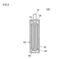
- FIG. 2 is a cross-sectional view schematically showing a II-II cross section of FIG.
- FIG. 3 is a schematic diagram for explaining a wound electrode body according to an embodiment of the present invention.
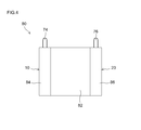
- FIG. 4 is a front view schematically showing a wound electrode body according to an embodiment of the present invention.
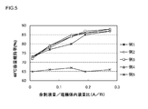
- FIG. 5 is a graph showing the relationship between the excess electrolyte amount / electrode body electrolyte ratio (A / B) and the capacity retention rate.
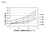
- FIG. 6 is a graph showing the relationship between the excess electrolyte amount / electrode body electrolyte amount ratio (A / B) and the resistance increase rate.
- FIG. 1 is a perspective view schematically showing a nonaqueous electrolyte secondary battery according to an embodiment of the present invention.
- FIG. 2 is a cross-sectional view schematically showing a II-II cross section of
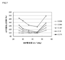
- FIG. 7 is a graph showing the relationship between the DBP absorption amount and the resistance increase rate.
- FIG. 8 is a diagram schematically showing the configuration of the positive electrode active material according to one embodiment of the present invention.
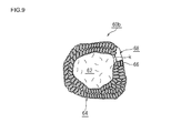
- FIG. 9 is a diagram schematically showing the configuration of the positive electrode active material according to one embodiment of the present invention.
- FIG. 10 is a side view schematically showing a vehicle (automobile) provided with the assembled battery according to the embodiment of the present invention.
- non-aqueous electrolyte lithium secondary battery in a form in which a wound electrode body (rolled electrode body) and a non-aqueous electrolyte are housed in a box-shaped case
- the present invention will be described in detail by taking (lithium ion secondary battery) as an example.
- FIGS. 1 and 2 A schematic configuration of a lithium secondary battery according to an embodiment of the present invention is shown in FIGS.
- the lithium secondary battery 100 includes a wound electrode body 80 and a battery case 50.
- FIG. 2 shows a II-II cross section in FIG.
- FIG. 3 is a view showing a wound electrode body 80.
- the lithium secondary battery 100 includes an electrode body (rolled electrode body) 80 in which a long positive electrode sheet 10 and a long negative electrode sheet 20 are wound through a long separator sheet 40.
- the wound electrode body 80 is housed in a case (box-shaped) case 50 that can be housed.
- the case 50 includes a bottomed box-shaped case main body 52 having an open upper end and a lid 54 that closes the opening.
- a metal material such as aluminum, steel, or Ni-plated SUS is preferably used (Ni-plated SUS in the present embodiment).
- molding resin materials, such as PPS and a polyimide resin, may be sufficient.
- the upper surface of the case 50 (that is, the lid 54) is provided with a positive electrode terminal 70 that is electrically connected to the positive electrode 10 of the wound electrode body 80 and a negative electrode terminal 72 that is electrically connected to the negative electrode 20 of the wound electrode body 80. It has been. Inside the case 50, the wound electrode body 80 is accommodated together with a non-aqueous electrolyte (not shown).
- the wound electrode body 80 As shown in FIG. 3, the wound electrode body 80 according to the present embodiment has a long (strip-shaped) sheet structure at a stage before assembling the wound electrode body 80.
- the positive electrode sheet 10 has a structure in which a positive electrode active material layer 14 containing a positive electrode active material is held on both surfaces of a long sheet-like foil-shaped positive electrode current collector 12. However, the positive electrode active material layer 14 is not attached to one side edge (the lower side edge portion in the figure) along the edge in the width direction of the positive electrode sheet 10, and the positive electrode current collector 12 has a constant width. An exposed positive electrode active material layer non-forming portion is formed.
- the negative electrode sheet 20 has a structure in which a negative electrode active material layer 24 containing a negative electrode active material is held on both surfaces of a long sheet-like foil-shaped negative electrode current collector 22.
- the negative electrode active material layer 24 is not attached to one side edge (the upper side edge portion in the figure) along the edge in the width direction of the negative electrode sheet 20, and the negative electrode current collector 22 is exposed with a certain width.
- a negative electrode active material layer non-formed portion is formed.
- the positive electrode sheet 10 and the negative electrode sheet 20 are laminated via the separator sheet 40 as shown in FIG.
- the positive electrode sheet 10 and the negative electrode sheet 20 are formed so that the positive electrode mixture layer non-formed portion of the positive electrode sheet 10 and the negative electrode composite material layer non-formed portion of the negative electrode sheet 20 protrude from both sides of the separator sheet 40 in the width direction. Are overlapped slightly in the width direction.
- the laminated body thus stacked is wound, and then the obtained wound body is crushed from the side surface direction and ablated, whereby a flat wound electrode body 80 can be produced.
- a wound core portion 82 (that is, the positive electrode active material layer 14 of the positive electrode sheet 10, the negative electrode active material layer 24 of the negative electrode sheet 20, and the separator sheet 40) is densely arranged in the central portion of the wound electrode body 80 in the winding axis direction. Laminated portions) are formed.
- the electrode active material layer non-formed portions of the positive electrode sheet 10 and the negative electrode sheet 20 protrude outward from the wound core portion 82 at both ends in the winding axis direction of the wound electrode body 80. As shown in FIG.
- the positive electrode side protruding portion (that is, the portion where the positive electrode active material layer 14 is not formed) 84 and the negative electrode side protruding portion (that is, the portion where the negative electrode active material layer 24 is not formed) 86 are provided on the positive electrode lead terminal 74. And a negative electrode lead terminal 76, respectively, and are electrically connected to the positive electrode terminal 70 and the negative electrode terminal 72, respectively.
- the constituent elements of the wound electrode body 80 except for the positive electrode sheet 10 may be the same as those of the conventional wound electrode body of a lithium secondary battery, and are not particularly limited.
- the positive electrode sheet 10 can be formed by applying a positive electrode active material layer 14 mainly composed of a positive electrode active material for a lithium secondary battery on a long positive electrode current collector 12.
- a positive electrode active material layer 14 mainly composed of a positive electrode active material for a lithium secondary battery
- an aluminum foil or other metal foil suitable for the positive electrode is preferably used.
- a sheet-like aluminum positive electrode current collector 12 is used.
- an aluminum sheet having a thickness of about 10 ⁇ m to 30 ⁇ m can be suitably used.
- the positive electrode active material layer 14 is composed of a positive electrode active material and other positive electrode active material layer forming components (for example, a binder, a conductive material, etc.) used as necessary.
- the positive electrode active material one or more materials conventionally used in lithium secondary batteries can be used without particular limitation, except that the DBP absorption amount described later satisfies a predetermined range. .
- lithium and a transition metal element such as lithium manganese oxide (LiMn 2 O 4 ), lithium cobalt oxide (LiCoO 2 ), and lithium nickel oxide (LiNiO 2 ) are used.
- a positive electrode active material mainly containing an oxide containing a constituent metal element (lithium transition metal oxide) can be given.
- a positive electrode active material typically, substantially a lithium nickel cobalt manganese composite oxide substantially composed of lithium nickel cobalt manganese composite oxide (for example, LiNi 1/3 Co 1/3 Mn 1/3 O 2 ).
- Application to a positive electrode active material comprising:
- the lithium nickel cobalt manganese composite oxide is an oxide having Li, Ni, Co, and Mn as constituent metal elements, and at least one other metal element in addition to Li, Ni, Co, and Mn (that is, It also includes oxides containing transition metal elements and / or typical metal elements other than Li, Ni, Co, and Mn.
- the metal element is, for example, one or two selected from the group consisting of Al, Cr, Fe, V, Mg, Ti, Zr, Nb, Mo, W, Cu, Zn, Ga, In, Sn, La, and Ce. It can be more than a seed element. The same applies to lithium nickel oxide, lithium cobalt oxide, and lithium manganese oxide. *
- a lithium transition metal compound (typically in particulate form), for example, a lithium transition metal compound powder prepared by a conventionally known method can be used as it is.
- a lithium transition metal compound powder substantially composed of secondary particles having an average particle size in the range of about 1 ⁇ m to 25 ⁇ m can be preferably used as the positive electrode active material.
- the positive electrode active material layer 14 can contain one kind or two or more kinds of materials that can be used as a component of the positive electrode active material layer in a general lithium secondary battery, if necessary.
- An example of such a material is a conductive material.
- a conductive material a carbon material such as carbon powder or carbon fiber is preferably used.
- conductive metal powder such as nickel powder may be used.
- various polymer materials that can function as a binder (binder) of the above-described constituent materials can be given.
- the ratio of the positive electrode active material to the entire positive electrode active material layer is preferably about 50% by mass or more (typically 50 to 95% by mass), preferably about 75 to 90% by mass. Preferably there is.
- the proportion of the conductive material in the positive electrode active material layer can be, for example, 3 to 25% by mass, and preferably about 3 to 15% by mass.
- the total content of these optional components is preferably about 7% by mass or less, and about 5% by mass. The following (for example, about 1 to 5% by mass) is preferable.
- the thickness of the positive electrode active material layer is preferably 45 ⁇ m to 240 ⁇ m, particularly preferably about 100 ⁇ m to 200 ⁇ m.
- the porosity of the positive electrode active material layer is preferably 20% to 60%, particularly preferably about 30% to 55%. If the porosity of the positive electrode active material layer is too small, the ion permeability of the positive electrode active material layer may be reduced. If the porosity of the positive electrode active material layer is too large, the mechanical properties of the positive electrode active material layer may be reduced. The strength may decrease.
- a positive electrode active material layer forming paste in which a positive electrode active material (typically granular) and other positive electrode active material layer forming components are dispersed in an appropriate solvent (preferably an aqueous solvent).
- an appropriate solvent preferably an aqueous solvent.
- a method of coating the electrode collector on one side or both sides (here, both sides) of the positive electrode current collector 12 and drying it can be preferably employed.
- an appropriate press treatment for example, various conventionally known press methods such as a roll press method, a flat plate press method, etc. can be employed
- the positive electrode active material layer The thickness and density of 14 can be adjusted.
- the negative electrode sheet 20 is formed by attaching a negative electrode active material layer 24 to both surfaces of a long sheet-like foil-shaped negative electrode current collector 22.
- the negative electrode active material layer 24 is not attached to one side edge along the edge in the width direction of the sheet-like electrode body, and the negative electrode current collector 22 is exposed with a certain width.
- a metal foil suitable for copper foil (this embodiment) and other negative electrodes is preferably used.
- a sheet-like copper negative electrode current collector 22 is used.
- a copper sheet having a thickness of about 5 ⁇ m to 30 ⁇ m can be suitably used.
- the negative electrode active material layer 24 is composed of a negative electrode active material and other negative electrode active material layer forming components (such as a binder) used as necessary.
- the negative electrode active material one type or two or more types of materials conventionally used in lithium secondary batteries can be used without any particular limitation.
- Preferable examples include carbon-based materials such as graphite carbon and amorphous carbon (graphite in the present embodiment), lithium-containing transition metal oxides, transition metal nitrides, and the like.
- the amount of the negative electrode active material contained in the negative electrode active material layer is not particularly limited, but is preferably about 90% by mass to 99% by mass, more preferably about 95% by mass to 99% by mass.
- the thickness of the negative electrode active material layer is preferably 50 ⁇ m to 210 ⁇ m, particularly preferably about 90 ⁇ m to 190 ⁇ m.
- the porosity of the negative electrode active material layer is preferably 20% to 60%, particularly preferably about 25% to 55%. If the porosity of the negative electrode active material layer is too small, the ion permeability of the negative electrode active material layer may be reduced. If the porosity of the negative electrode active material layer is too large, the mechanical properties of the negative electrode active material layer may be reduced. The strength may decrease.
- a negative electrode active material layer forming paste in which a negative electrode active material (typically granular) and other negative electrode active material layer forming components are dispersed in a suitable solvent is used.
- an appropriate press treatment for example, various conventionally known press methods such as a roll press method and a flat plate press method can be adopted) is performed, whereby the negative electrode active material layer The thickness and density of 24 can be adjusted.
- Suitable separator sheets 40 used between the positive and negative electrode sheets 10 and 20 include those made of a porous polyolefin resin.
- a porous separator sheet made of synthetic resin for example, made of polyolefin such as polyethylene (PE) or polypropylene (PP)
- the structure of the separator sheet 40 may be a single layer structure or a multilayer structure.
- it is constituted by a three-layer structure of a polypropylene (PP) layer, a polyethylene (PE) layer laminated on the polypropylene (PP) layer, and a polypropylene (PP) layer laminated on the polyethylene (PE) layer. Also good.
- the wound electrode body 80 having such a configuration is accommodated in the case main body 52, and an appropriate nonaqueous electrolytic solution is disposed (injected) into the case main body 52.
- the nonaqueous electrolytic solution accommodated in the case main body 52 together with the wound electrode body 80 includes a lithium salt as a supporting salt (electrolyte) in an organic solvent (nonaqueous solvent).
- a lithium salt for example, a known lithium salt conventionally used as a supporting salt for a non-aqueous electrolyte of a lithium secondary battery can be appropriately selected and used.
- lithium salt LiPF 6 , LiBF 4 , LiClO 4 , LiAsF 6 , Li (CF 3 SO 2 ) 2 N, LiCF 3 SO 3 , LiaC 4 F 9 SO 3 , LiN (CF 3 SO 2 ) 2
- Examples include LiC (CF 3 SO 2 ) 3 , LiI and the like.
- These supporting salts can be used alone or in combination of two or more. Particularly preferred examples include LiPF 6 , LiBF 4 , LiClO 4 , and LiAsF 6 .
- These supporting salts are preferable in that high ion conductivity can be obtained and cycle characteristics can be improved.
- the non-aqueous electrolyte is preferably prepared, for example, so that the concentration of the supporting salt is within a range of 0.7 to 1.6 mol / L.
- an organic solvent used in a general lithium secondary battery can be appropriately selected and used.
- particularly preferred non-aqueous solvents include cyclic carbonates such as ethylene carbonate (EC), propylene carbonate (PC), and butylene carbonate, and chain carbonates such as dimethyl carbonate (DMC) and ethyl methyl carbonate (EMC). Is done.
- cyclic carbonates such as ethylene carbonate (EC), propylene carbonate (PC), and butylene carbonate
- chain carbonates such as dimethyl carbonate (DMC) and ethyl methyl carbonate (EMC). Is done.
- DMC dimethyl carbonate
- EMC ethyl methyl carbonate
- These organic solvents can be used alone or in combination of two or more. Among these, it is preferable to use a mixed solvent composed of a cyclic carbonate and a chain carbonate.
- a mixed solvent containing EC, EMC, and DMC at a volume ratio of 3: 4: 3 contains LiPF 6 as a supporting salt at a concentration of 0.7 to 1.6 mol / L (eg, about 1 mol / L).
- a non-aqueous electrolyte can be preferably used.
- the non-aqueous electrolyte is housed in the case body 52 together with the wound electrode body 80, and the opening of the case body 52 is sealed with the lid body 54, whereby the lithium secondary battery 100 according to this embodiment is constructed (assembled). ) Is completed.
- positioning (injection) process of electrolyte solution can be performed similarly to the method currently performed by manufacture of the conventional lithium secondary battery. Thereafter, the battery is conditioned (initial charge / discharge). You may perform processes, such as degassing and a quality inspection, as needed.
- the excess electrolyte amount (A) existing outside the wound electrode body and the electrolyte in the electrode impregnated in the wound electrode body The liquid ratio (A / B) to the amount (B) is 0.05 to 0.2. Further, the DBP absorption amount of the positive electrode active material provided in the positive electrode sheet 10 is 30 (ml / 100 g) to 50 (ml / 100 g).
- the excess electrolyte amount / electrode body electrolyte amount ratio (A / B) and the DBP absorption amount of the positive electrode active material will be described in this order.
- the excess electrolyte amount / electrode internal electrolyte amount ratio is the ratio of the excess electrolyte amount A to the electrode internal electrolyte amount B, and is indicated by A / B.
- the electrolytic solution in the electrode is an electrolytic solution impregnated (absorbed and retained) in the electrode body.
- the surplus electrolyte is an electrolyte that can flow through the electrode body and exists in a region other than the electrode body (that is, not impregnated in the electrode body).
- the surplus electrolyte may be disposed in a gap between the inner wall 56 (FIG. 2) of the battery case and the wound electrode body 80.
- Excess electrolyte amount A and electrode electrolyte amount B can be measured according to the following procedure.
- Procedure 1 The wound electrode body 80 is accommodated in the case main body 52.
- Procedure 2 Arbitrary amount X of non-aqueous electrolyte is poured into the case main body 52, the wound electrode body 80 is soaked with the non-aqueous electrolyte, and left in that state for 24 hours.
- Procedure 3 The case main body 52 is tilted, and excess nonaqueous electrolyte solution that has not soaked into the wound electrode body 80 is discharged.
- the surplus nonaqueous electrolyte amount discharged from the case body 52 corresponds to the surplus electrolyte amount A
- the value obtained by subtracting the surplus electrolyte amount A from the arbitrary amount X first injected into the case body 52 ( XA) corresponds to the electrolyte volume B in the electrode body.
- the amount of the electrolytic solution may be volume based or mass based. Mutual conversion is possible by converting the specific gravity of the electrolyte.
- the DBP absorption amount (mL / 100 g) is determined in accordance with JIS K6217-4 “Carbon black for rubber—Basic characteristics—Part 4: Determination of DBP absorption amount”.
- DBP dibutyl phthalate
- the powder to be inspected is titrated with a constant speed burette, and a change in viscosity characteristics is measured with a torque detector.
- the amount of reagent liquid added per unit weight of the inspection target powder corresponding to 70% of the generated maximum torque is defined as DBP absorption (mL / 100 g).
- the DBP absorption amount indicates how much the electrolytic solution impregnated in the positive electrode active material layer can be absorbed by the positive electrode active material. That is, the higher the DBP absorption amount, the easier the electrolyte solution impregnated in the positive electrode active material layer is absorbed by the positive electrode active material.
- the surplus electrolyte amount A existing outside the wound electrode body 80 and the wound electrode body 80 are impregnated.
- the liquid volume ratio A / B with the electrolyte volume B in the electrode is 0.05 to 0.2.
- the DBP absorption amount of the positive electrode active material included in the positive electrode sheet 10 is 30 (ml / 100 g) or more.
- the ratio A / B between the excess electrolyte amount A existing outside the electrode body 80 and the electrode body electrolyte amount B impregnated in the electrode body 80 is 0.05 to 0.2.
- the amount of surplus electrolyte existing in the free state outside the electrode body 80 is increased, and even when the electrode body 80 is drained due to repeated charge and discharge, the electrolyte is appropriately replenished from the surplus electrolyte.
- the amount of electrolyte in the electrode can be quickly recovered. Therefore, it is possible to reduce the capacity deterioration accompanying the charge / discharge cycle particularly at a high temperature (for example, around 60 ° C.).
- the DBP absorption amount of the positive electrode active material included in the positive electrode sheet 10 is set to 30 (ml / 100 g) or more.
- the non-aqueous electrolyte impregnated in the positive electrode active material layer 14 is easily absorbed by the positive electrode active material, and the positive electrode active material layer 14 is dried up. (Ion shortage) hardly occurs. For this reason, although it is the structure which has the said excess electrolyte solution, the performance degradation accompanying the high-rate charging / discharging cycle especially at low temperature can be suppressed.
- the liquid volume ratio (A / B) is generally about 0.05 to 0.2, preferably 0.068 to 0.19. If the liquid ratio (A / B) is too small, the amount of electrolyte in the electrode cannot be quickly recovered when the liquid withers, and performance degradation may occur during a high-temperature cycle. On the other hand, if the liquid ratio (A / B) is too large, the low-temperature high-rate cycle characteristics may deteriorate. From the viewpoint of improving the high-temperature cycle characteristics, the liquid volume ratio (A / B) is suitably 0.05 or more, preferably 0.068 or more, and particularly preferably 0.14 or more.
- the liquid volume ratio (A / B) is suitably 0.2 or less, preferably 0.19 or less, particularly preferably 0.14 or less. is there.
- the liquid volume ratio (A / B) is suitably 0.05 to 0.2, preferably 0.068 to 0.19, The preferred range is 0.1 to 0.15.
- the DBP absorption amount of the positive electrode active material is suitably 30 (ml / 100 g) to 50 (ml / 100 g), preferably 36 (ml / 100 g) to 50 (ml / 100 g), It is preferably 40 (ml / 100 g) to 45 (ml / 100 g).
- a positive electrode active material having a DBP absorption of less than 30 (ml / 100 g) is used, the effect of suppressing low-temperature high-rate cycle deterioration may not be sufficiently obtained.
- the resulting positive electrode active material layer has poor adhesion, and peels off from the underlying positive electrode current collector during the battery manufacturing process, or performance degradation occurs during the charge / discharge cycle. It may be easy to happen.
- active material particles having a composition represented by Li 1.15 Ni 0.33 Co 0.33 Mn 0.33 O 2 were used for the positive electrode active material.
- the generation process of the active material particles is devised so that the secondary particles of the active material particles can be formed into hollow shapes, spherical particles, or irregularly shaped particles so that positive electrode active materials having different structures can be obtained.
- the positive electrode active material has a difference in DBP absorption (ml / 100 g) due to such a structural difference.
- the DBP absorption amounts are “26 (ml / 100 g)”, “30 (ml / 100 g)”, “36 (ml / 100 g)”, “45 (ml / 100 g)”, “54 (ml / ml), respectively. 100 g) ”was prepared.
- the lithium secondary battery for a test was produced by changing the surplus electrolyte amount / electrode body electrolyte amount ratio (A / B). Then, a cycle test was performed using the test battery, and the influence of the DBP absorption amount of the positive electrode active material and the excess electrolyte amount / electrode body electrolyte amount ratio (A / B) on the battery performance was evaluated. .
- a Li 1.15 Ni 0.33 Co 0.33 Mn 0.33 O 2 powder having a DBP absorption of 26 (ml / 100 g) and an average particle size of about 6 ⁇ m was used as the positive electrode active material.
- Li 1.15 Ni 0.33 Co 0.33 Mn 0.33 O 2 powder as a positive electrode active material, acetylene black (AB) as a conductive material, and polyvinylidene fluoride (PVdF) as a binder have a mass ratio of these materials.
- a paste for forming a positive electrode active material layer was prepared by mixing in N-methyl-2-pyrrolidone (NMP) at a ratio of 87: 10: 3.
- NMP N-methyl-2-pyrrolidone
- the positive electrode active material layer forming paste was formed on both surfaces of the positive electrode current collector 12 by applying the paste for forming the positive electrode active material layer on both surfaces of a long sheet-like aluminum foil having a thickness of 15 ⁇ m and drying it. A positive electrode sheet 10 was produced.
- the basis weight (coating amount) of the positive electrode active material layer 14 was adjusted to be about 30 mg / cm 2 (solid content basis) for both surfaces. After drying, pressing was performed so that the porosity of the positive electrode active material layer 14 was about 30%.
- SBR styrene butadiene
- the flat wound electrode body 80 was produced by winding the positive electrode sheet 10 and the negative electrode sheet 20 through two separator sheets (porous polypropylene) 40 and crushing the wound wound body from the side surface direction. .
- the wound electrode body 80 obtained in this way was accommodated in the battery case 50 together with the non-aqueous electrolyte, and the opening of the battery case 50 was hermetically sealed.
- a non-aqueous electrolyte a mixed solvent containing ethylene carbonate (EC), ethyl methyl carbonate (EMC), and dimethyl carbonate (DMC) in a volume ratio of 3: 4: 3 contains about 1 mol / liter of LiPF 6 as a supporting salt.
- the non-aqueous electrolyte solution contained at a concentration of was used. Thereafter, an initial charge / discharge treatment (conditioning) was performed by a conventional method to obtain a test lithium secondary battery.
- the ratios A / B between the amount A of excess electrolyte existing outside the wound electrode body 80 and the amount B of electrolyte in the electrode impregnated in the wound electrode body 80 are different from each other.
- a secondary battery was produced.
- the excess electrolyte amount / electrode body electrolyte amount ratio (A / B) is “0.008”, “0.068”, “0.142”, “0.19”, “0”, respectively. . 275 "was manufactured in total.
- the excess electrolyte amount / electrode body electrolyte amount ratio (A / B) was adjusted by changing the amount of the non-aqueous electrolyte injected into the battery case 50.
- the method for measuring the excess electrolyte amount A and the electrode body electrolyte amount B is as described above.
- Example 2 A lithium secondary battery was produced in the same manner as in Example 1 except that positive electrode active material particles having a DBP absorption amount of 30 (ml / 100 g) and an average particle size of about 6 ⁇ m were used.
- Example 3 A lithium secondary battery was fabricated in the same manner as in Example 1 except that positive electrode active material particles having a DBP absorption amount of 36 (ml / 100 g) and an average particle size of about 6 ⁇ m were used.
- Example 4 A lithium secondary battery was produced in the same manner as in Example 1 except that positive electrode active material particles having a DBP absorption amount of 45 (ml / 100 g) and an average particle size of about 6 ⁇ m were used.
- Example 5 A lithium secondary battery was produced in the same manner as in Example 1, except that positive electrode active material particles having a DBP absorption amount of 54 (ml / 100 g) and an average particle size of about 6 ⁇ m were used.
- the initial capacity of each test lithium secondary battery obtained as described above was measured. First, in an environmental atmosphere of 25 ° C., the battery was charged by a constant current and constant voltage method with a current of 1 C and a voltage of 4.1 V until the charging time was 3 hours. After 10 minutes of rest, the battery after charging is discharged at 25 ° C. with a constant current of 1/3 C up to 3 V until the discharge time is 6 hours. After 10 minutes of rest, the current 1/3 C, It discharged until the discharge time became 4 hours by the constant current constant voltage system of the voltage 3V. The discharge capacity at this time was measured as the initial capacity.
- each test lithium secondary battery was adjusted to a SOC (State of Charge) 60% charge state by constant current constant voltage (CC-CV) charging in an environmental atmosphere of 25 ° C. Then, discharge was performed at 25 ° C. with current values of 0.3 C, 1 C, and 3 C for 10 seconds, and a voltage value 10 seconds after the start of discharge was measured.
- Each measurement point current value (I), voltage value (V)) is plotted on the IV characteristic graph (horizontal axis (X axis) is I and vertical axis (Y axis) is V). An approximate straight line passing through was drawn, and the initial resistance value was calculated from the slope of the approximate straight line.
- FIG. 5 is a graph showing the relationship between the excess electrolyte amount / electrode body electrolyte ratio (A / B) and the capacity retention rate.
- the capacity retention ratio tended to increase as the ratio of surplus electrolyte amount / intraelectrode electrolyte amount ratio (A / B) increased.
- the capacity retention ratio exceeded 77% when the excess electrolyte amount / electrode body electrolyte amount ratio (A / B) was 0.068 or more.
- the excess electrolyte amount / electrode body electrolyte amount ratio (A / B) was 0.142 or more, a very high capacity retention rate of 80% or more was achieved.
- the ratio of the excess electrolyte amount / the electrolyte amount in the electrode (A / B) is generally suitably 0.05 or more, preferably 0.068 or more, particularly preferably 0.142 or more.
- the DBP absorption amount of the positive electrode active material is approximately 50 (ml / 100 g) or less.
- FIG. 6 is a graph showing the relationship between the excess electrolyte amount / electrode body electrolyte amount ratio (A / B) and the resistance increase rate
- FIG. 7 shows the relationship between the DBP absorption amount of the positive electrode active material and the resistance increase rate. It is a graph to show.
- the rate of increase in resistance tended to increase as the excess electrolyte amount / intraelectrode electrolyte amount ratio (A / B) increased.
- the ratio of the excess electrolyte amount / the electrolyte amount in the electrode (A / B) exceeded 0.2, the rate of increase in resistance significantly increased. From this result, the ratio of excess electrolyte amount / electrolyte amount in the electrode (A / B) is suitably about 0.2 or less, particularly preferably 0.19 or less.
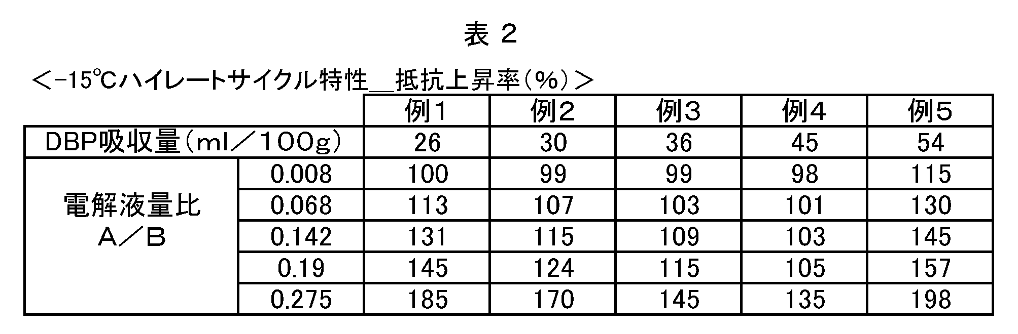
- the DBP absorption amount is 30 to 45 (ml / 100 g).
- the battery according to Example 4 had a lower resistance increase rate after the high-rate cycle than the batteries according to Examples 1 and 5. That is, it was confirmed that by increasing the DBP absorption amount to 30 to 45 (ml / 100 g), an increase in resistance due to an increase in the excess electrolyte amount was suppressed. From this result, the DBP absorption amount is suitably about 30 (ml / 100 g) to 50 (ml / 100 g), particularly preferably 30 (ml / 100 g) to 45 (ml / 100 g).
- the DBP absorption amount of the positive electrode active material in a battery having an excess amount of electrolyte, it is effective to set the DBP absorption amount of the positive electrode active material to 30 (ml / 100 g) or more in order to improve the low temperature high rate cycle characteristics.
- a positive electrode active material composed of solid particles has a limit in increasing the DBP absorption amount of the positive electrode active material. For this reason, in order to make the DBP absorption amount of the positive electrode active material layer 30 (ml / 100 g), it is important to select a positive electrode active material suitable for it.
- the present inventor has studied to select a positive electrode active material that has pores in the positive electrode active material itself and increases the DBP absorption amount of the positive electrode active material layer.
- the positive electrode active material may be formed of secondary particles 64 in which a plurality of primary particles 66 of a lithium transition metal oxide are aggregated.
- a positive electrode active material 60a in which the hollow portion 62 is formed in the secondary particle 64 may be used.
- a large number of fine pores are desirably formed between the primary particles 66 in the secondary particles 64, so that the nonaqueous electrolyte solution can penetrate into the hollow portion 62.
- the DBP absorption amount of the positive electrode active material 60a can be easily adjusted to 30 (ml / 100 g) or more.
- the structure of the positive electrode active material 60 a having the hollow portion 62 is appropriately referred to as “hollow structure”.
- the positive electrode active material 60 b further includes a through hole 68 that penetrates the secondary particle 64 so as to connect the hollow portion 62 and the outside. Also good.
- the structure of the positive electrode active material 60b having such a through hole 68 is appropriately referred to as “perforated hollow structure”.
- the electrolytic solution easily passes between the hollow portion 62 and the outside through the through hole 68, and the electrolytic solution in the hollow portion 62 is appropriately replaced. For this reason, the withering of the electrolyte in the hollow portion 62 is unlikely to occur.
- the primary particles 66 of the positive electrode active material 60b can be utilized more actively in the hollow portion 62.
- the DBP absorption amount of the positive electrode active material 60b can be adjusted to 30 (ml / 100 g) or more, and the battery performance can be further improved.
- the opening width k of the through holes 68 is 0.01 ⁇ m or more on average. As a result, the electrolyte enters the hollow portion 62 more reliably, and the above-described effect is easily obtained. Moreover, the opening width k of the through-hole 68 is good in average being 2.0 micrometers or less.
- the opening width k of the through-hole 68 is a passing length (penetration) in a portion where the through-hole 68 is narrowest in a path from the outside of the active material particle through the secondary particle to the hollow portion 62. The inner diameter of the hole 68).
- the opening width k of the through hole 68 may be an average of 2.0 ⁇ m or less, more preferably an average of 1.0 ⁇ m or less, and even more preferably an average of 0.5 ⁇ m or less.
- the number of through holes 68 may be about 1 to 20 on average per one particle of the positive electrode active material 60b, and more preferably about 1 to 5 on average. According to the positive electrode active material 60b having such a structure, good battery performance can be more stably exhibited.
- the number of through-holes 68 in the positive electrode active material 60b having a perforated hollow structure is, for example, the number of through-holes per particle for at least 10 or more active material particles arbitrarily selected, and the arithmetic average value thereof. It is good to ask for.
- the method for producing the positive electrode active material 60b having a perforated hollow structure may include, for example, a raw material hydroxide generation step, a mixing step, and a firing step.
- the raw material hydroxide generation step is a step in which ammonium ions are supplied to the aqueous solution of the transition metal compound to precipitate the transition metal hydroxide particles from the aqueous solution.
- the aqueous solution may contain at least one transition metal element constituting the lithium transition metal oxide.
- the raw material hydroxide generation step includes a nucleation stage in which a transition metal hydroxide is precipitated from an aqueous solution at a pH of 12 or more and an ammonium ion concentration of 25 g / L or less, and the precipitated transition metal hydroxide is less than pH 12 and ammonium. And a particle growth stage for growing at an ion concentration of 3 g / L or more.
- the mixing step is a step of preparing an unfired mixture by mixing the transition metal hydroxide particles obtained in the raw material hydroxide generating step and the lithium compound.
- the firing step is a step of obtaining active material particles by firing the mixture obtained in the mixing step. According to this manufacturing method, the positive electrode active material 60b having a perforated hollow structure can be appropriately manufactured.
- the firing step is preferably performed so that the maximum firing temperature is 800 ° C. to 1100 ° C.
- the active material particle which has desired average hardness can be manufactured suitably.
- This firing step is preferably performed so that, for example, secondary particles that do not substantially have a gap at the grain boundaries of the primary particles are formed in portions other than the hollow portion 62 and the through holes 68.
- the firing step includes a first firing stage in which the mixture is fired at a temperature T1 of 700 ° C. or more and 900 ° C. or less, and a result obtained through the first firing step is 800 ° C. or more and 1100 ° C. or less and the first firing stage. And a second firing stage in which firing is performed at a temperature T2 higher than the firing temperature T1.
- the firing step includes a first firing stage in which the mixture is fired at a temperature T1 of 700 ° C. or more and 900 ° C. or less, and a result obtained through the first firing stage.
- a second firing stage in which firing is performed at a temperature T2 that is 800 ° C. or more and 1100 ° C. or less and higher than a firing temperature T1 in the first firing stage.
- the BET specific surface area of the positive electrode active materials 60a and 60b is preferably 0.5 to 1.9 m 2 / g.
- a positive electrode active material satisfying such a BET specific surface area may be used for a positive electrode of a lithium secondary battery to give a battery that stably exhibits higher performance.
- a lithium secondary battery having a low internal resistance (in other words, good output characteristics) and having a small increase in resistance even by a charge / discharge cycle (particularly, a charge / discharge cycle including discharge at a high rate) can be constructed.
- the “hollow structure” positive electrode active material 60a and the “perforated hollow structure” positive electrode active material 60b described above are suitable forms of a positive electrode active material having a BET specific surface area of 0.5 to 1.9 m 2 / g. obtain.
- the “hollow structure” positive electrode active material 60a and the “perforated hollow structure” positive electrode active material 60b are obtained by secondary particles obtained by granulating primary particles by a spray drying method (internally small pores). Compared with porous secondary particles) having a high hardness, it can be of high hardness. For example, in a dynamic hardness measurement performed using a flat diamond indenter with a diameter of 50 ⁇ m and a load speed of 0.5 mN / sec to 3 mN / sec, the average hardness can be 0.5 MPa or more.
- the average hardness of the positive electrode active material 60a having a hollow structure and the positive electrode active material 60b having a perforated hollow structure is approximately 0.5 MPa or more.
- the average hardness means a value obtained by dynamic hardness measurement performed under the condition of a load speed of 0.5 mN / second to 3 mN / second using a flat diamond indenter having a diameter of 50 ⁇ m.
- the active material particles having a hollow structure as shown in FIGS. 8 and 9 and having a high average hardness in other words, a high shape maintaining property
- a charge / discharge cycle can contribute to the construction of a lithium secondary battery with little increase in resistance.
- the positive electrode active material 60a having a hollow structure or the positive electrode active material 60b having a perforated hollow structure may be a lithium transition metal oxide having a layered structure containing nickel as a constituent element.
- the positive electrode active material 60a having a hollow structure and the positive electrode active material 60b having a perforated hollow structure may be a lithium transition metal oxide having a layered structure including nickel, cobalt, and manganese as constituent elements.
- the positive electrode active material 60a having a hollow structure and the positive electrode active material 60b having a perforated hollow structure preferably have an average particle diameter in the range of about 3 ⁇ m to 10 ⁇ m, for example.
- the average opening size of the through holes 68 of the positive electrode active material 60b having a perforated hollow structure is preferably 1 ⁇ 2 or less of the average particle diameter of the positive electrode active material 60b. Since the positive electrode active material 60b has the above average opening size in an appropriate range, the desired average hardness can be easily ensured while appropriately exhibiting the effect of improving battery performance due to having a perforated hollow structure. . Therefore, good battery performance can be exhibited more stably.
- the positive electrode active material 60a having a hollow structure and the positive electrode active material 60b having a perforated hollow structure have a hollow portion 62 formed in the secondary particle 64, so that the DBP absorption amount of the positive electrode active material is 30 to 50 (ml). / 100 g). Therefore, in a battery in which the ratio of excess electrolyte amount / electrolyte amount in electrode (A / B) is increased, the low temperature high rate cycle characteristics can be improved.
- a suitable positive electrode active material was mentioned as a positive electrode active material contained in the positive electrode active material layer 14 of a lithium secondary battery, especially as a positive electrode active material of the lithium secondary battery which concerns on this invention above, It is not limited.
- any of the non-aqueous electrolyte secondary batteries disclosed herein is less susceptible to capacity deterioration associated with charge / discharge cycles at high temperatures, and is also preferably suppressed in resistance increase associated with high-rate charge / discharge cycles at low temperatures.
- Performance suitable as a non-aqueous electrolyte secondary battery mounted on a vehicle is provided. Therefore, according to this invention, as shown in FIG. 10, the vehicle 1 provided with the nonaqueous electrolyte secondary battery 100 disclosed here is provided.
- a vehicle for example, an automobile
- the battery as a power source typically, a power source of a hybrid vehicle or an electric vehicle
- Non-aqueous electrolyte secondary battery large capacity type with a theoretical capacity of 1 Ah or more (more than 3 Ah), 10 C or more (for example, 10 C to 50 C), or even 20 C or more (for example, 20 C to 40 C) with high rate charge / discharge Examples include non-aqueous electrolyte secondary batteries that are assumed to be used in charge / discharge cycles.
- non-aqueous electrolyte secondary battery that is excellent in charge / discharge cycle characteristics at high temperatures and also excellent in high-rate charge / discharge cycle characteristics at low temperatures.
Landscapes
- Chemical & Material Sciences (AREA)
- Chemical Kinetics & Catalysis (AREA)
- Electrochemistry (AREA)
- General Chemical & Material Sciences (AREA)
- Engineering & Computer Science (AREA)
- Inorganic Chemistry (AREA)
- Manufacturing & Machinery (AREA)
- General Physics & Mathematics (AREA)
- Condensed Matter Physics & Semiconductors (AREA)
- Physics & Mathematics (AREA)
- Materials Engineering (AREA)
- Secondary Cells (AREA)
- Battery Electrode And Active Subsutance (AREA)
Abstract
Description
本発明の一実施形態に係るリチウム二次電池の概略構成を図1~4に示す。このリチウム二次電池100は、図1及び図2に示すように、捲回電極体80と電池ケース50とを備えている。図2は、図1中のII-II断面を示している。また、図3は、捲回電極体80を示す図である。このリチウム二次電池100は、長尺状の正極シート10と長尺状の負極シート20が長尺状のセパレータシート40を介して捲回された形態の電極体(捲回電極体)80が、図示しない非水電解質(非水電解液)とともに、該捲回電極体80を収容し得る形状(箱型)のケース50に収容された構成を有する。
本実施形態に係る捲回電極体80は、図3に示すように、捲回電極体80を組み立てる前段階において長尺状(帯状)のシート構造を有している。
正極シート10は、長尺状の正極集電体12の上にリチウム二次電池用正極活物質を主成分とする正極活物質層14が付与されて形成され得る。正極集電体12にはアルミニウム箔その他の正極に適する金属箔が好適に使用される。本実施形態では、シート状のアルミニウム製の正極集電体12が用いられる。例えば、厚みが10μm~30μm程度のアルミニウムシートを好適に用いることができる。
正極活物質層14は、正極活物質と、必要に応じて使用される他の正極活物質層形成成分(例えばバインダ、導電材等)とから構成されている。正極活物質としては、後述するDBP吸収量が所定範囲を満足する点を除いては、従来からリチウム二次電池に用いられる物質の一種または二種以上を特に限定することなく使用することができる。ここに開示される技術の好ましい適用対象として、リチウムマンガン酸化物(LiMn2O4)、リチウムコバルト酸化物(LiCoO2)、リチウムニッケル酸化物(LiNiO2)等の、リチウムと遷移金属元素とを構成金属元素として含む酸化物(リチウム遷移金属酸化物)を主成分とする正極活物質が挙げられる。中でも、リチウムニッケルコバルトマンガン複合酸化物(例えばLiNi1/3Co1/3Mn1/3O2)を主成分とする正極活物質(典型的には、実質的にリチウムニッケルコバルトマンガン複合酸化物からなる正極活物質)への適用が好ましい。
負極シート20も正極シート10と同様に、長尺シート状の箔状の負極集電体22の両面に負極活物質層24が付着されて形成されている。ただし、負極活物質層24はシート状電極体の幅方向の端辺に沿う一方の側縁には付着されず、負極集電体22を一定の幅にて露出させている。
負極活物質層24は、負極活物質と、必要に応じて使用される他の負極活物質層形成成分(例えばバインダ等)とから構成されている。負極活物質としては、従来からリチウム二次電池に用いられる物質の一種または二種以上を特に限定することなく使用することができる。好適例として、グラファイトカーボン、アモルファスカーボン等の炭素系材料(本実施形態では黒鉛)、リチウム含有遷移金属酸化物や遷移金属窒化物等が挙げられる。負極活物質層に含まれる負極活物質の量は特に限定されないが、好ましくは90質量%~99質量%程度、より好ましくは95質量%~99質量%程度である。
正負極シート10、20間に使用される好適なセパレータシート40としては多孔質ポリオレフィン系樹脂で構成されたものが挙げられる。例えば、合成樹脂製(例えばポリエチレン(PE)、ポリプロピレン(PP)等のポリオレフィン製)多孔質セパレータシートが好適に使用し得る。セパレータシート40の構造は、単層構造であってもよく、多層構造であってもよい。例えば、ポリプロピレン(PP)層と、ポリプロピレン(PP)層上に積層されたポリエチレン(PE)層と、ポリエチレン(PE)層上に積層されたポリプロピレン(PP)層との3層構造により構成してもよい。
かかる構成の捲回電極体80をケース本体52に収容し、そのケース本体52内に適当な非水電解液を配置(注液)する。ケース本体52内に上記捲回電極体80と共に収容される非水電解液は、支持塩(電解質)としてのリチウム塩を有機溶媒(非水溶媒)中に含んだものである。リチウム塩としては、例えば、従来からリチウム二次電池の非水電解液の支持塩として用いられている公知のリチウム塩を、適宜選択して使用することができる。例えば、かかるリチウム塩として、LiPF6、LiBF4、LiClO4、LiAsF6、Li(CF3SO2)2N、LiCF3SO3、LiaC4F9SO3、LiN(CF3SO2)2、LiC(CF3SO2)3、LiI等が例示される。かかる支持塩は、一種のみを単独で、または二種以上を組み合わせて用いることができる。特に好ましい例として、LiPF6、LiBF4、LiClO4、LiAsF6が挙げられる。これらの支持塩(電解質)は高いイオン伝導性を得ることができると共に、サイクル特性を向上させることができる点で好ましい。上記非水電解液は、例えば、上記支持塩の濃度が0.7~1.6mol/Lの範囲内となるように調製することが好ましい。
余剰電解液量/電極体内電解液量比は、電極体内電解液量Bに対する余剰電解液量Aの比であり、A/Bで示される。ここで電極体内電解液とは、電極体に含浸(吸収保持)されている電解液のことである。また、余剰電解液とは、電極体と流通可能で電極体以外の領域に存在する(即ち電極体に含浸されていない)電解液のことである。余剰電解液は、例えば、電池ケースの内壁56(図2)と捲回電極体80との隙間に配置され得る。余剰電解液量Aおよび電極体内電解液量Bは次の手順に沿って測定することができる。
手順1:捲回電極体80をケース本体52に収容する。
手順2:任意量Xの非水電解液をケース本体52に注液し、捲回電極体80に非水電解液を染み込ませ、その状態で24時間放置する。
手順3:ケース本体52を傾け、捲回電極体80に染み込んでいない余剰の非水電解液を排出する。
このとき、ケース本体52から排出された余剰の非水電解液量が余剰電解液量Aに相当し、最初にケース本体52に注液した任意量Xから余剰電解液量Aを減じた値(X-A)が電極体内電解液量Bに相当する。なお、上記電解液量は体積基準であっても質量基準であってもよい。電解液の比重を換算することで相互に変換できる。
DBP吸収量(mL/100g)は、JIS K6217-4「ゴム用カーボンブラック‐基本特性‐第4部:DBP吸収量の求め方」に準拠して求める。ここでは、試薬液体としてDBP(ジブチルフタレート)を用い、検査対象粉末に定速度ビュレットで滴定し、粘度特性の変化をトルク検出器によって測定する。そして、発生した最大トルクの70%のトルクに対応する、検査対象粉末の単位重量当りの試薬液体の添加量をDBP吸収量(mL/100g)とする。DBP吸収量の測定器としては、例えば、株式会社あさひ総研の吸収量測定装置S410を使用するとよい。かかるDBP吸収量は、正極活物質層に含浸した電解液がどの程度、正極活物質に吸収され得るかを示している。すなわち、DBP吸収量が高ければ高いほど、正極活物質層に含浸した電解液が、正極活物質に吸収され易いことを示している。
[正極シート]
本例では、正極活物質として、DBP吸収量26(ml/100g)、平均粒径6μm程度のLi1.15Ni0.33Co0.33Mn0.33O2粉末を用いた。まず、正極活物質としてのLi1.15Ni0.33Co0.33Mn0.33O2粉末と、導電材としてのアセチレンブラック(AB)と、バインダとしてのポリフッ化ビニリデン(PVdF)とを、これらの材料の質量比が87:10:3となるようにN-メチル-2-ピロリドン(NMP)中で混合して、正極活物質層形成用ペーストを調製した。この正極活物質層形成用ペーストを、長尺シート状の厚み15μmのアルミニウム箔の両面に帯状に塗布して乾燥することにより、正極集電体12の両面に正極活物質層14が設けられた正極シート10を作製した。正極活物質層14の目付け量(塗布量)は、両面合わせて約30mg/cm2(固形分基準)となるように調節した。乾燥後、正極活物質層14の空孔率が約30%となるようにプレスした。
負極活物質としては、平均粒径10μm程度のグラファイト粉末を用いた。まず、負極活物質としてのグラファイト粉末とバインダとしてのスチレンブタジエンゴム(SBR)と増粘剤としてのカルボキシメチルセルロース(CMC)とを、これらの材料の質量比が98:1:1となるように水に分散させて負極活物質層用ペーストを調製した。この負極活物質層用ペーストを厚み20μmの長尺シート状の銅箔(負極集電体22)の両面に塗布し、負極集電体22の両面に負極活物質層24が設けられた負極シート20を作製した。負極活物質層24の目付け量(塗布量)は、両面合わせて約25mg/cm2(固形分基準)となるように調節した。乾燥後、負極活物質層24の空孔率が約35%となるようにプレスした。
正極シート10及び負極シート20を2枚のセパレータシート(多孔質ポリプロピレン)40を介して捲回し、該捲回した捲回体を側面方向から押しつぶすことによって扁平状の捲回電極体80を作製した。このようにして得られた捲回電極体80を非水電解液とともに電池ケース50に収容し、電池ケース50の開口部を気密に封口した。非水電解液としてはエチレンカーボネート(EC)とエチルメチルカーボネート(EMC)とジメチルカーボネート(DMC)とを3:4:3の体積比で含む混合溶媒に支持塩としてのLiPF6を約1mol/リットルの濃度で含有させた非水電解液を使用した。その後、常法により初期充放電処理(コンディショニング)を行って試験用のリチウム二次電池を得た。
また、本例では、捲回電極体80の外部に存在する余剰電解液量Aと、捲回電極体80に含浸している電極体内電解液量Bとの比A/Bが、それぞれ異なるリチウム二次電池を作製した。具体的には、余剰電解液量/電極体内電解液量比(A/B)がそれぞれ、「0.008」、「0.068」、「0.142」、「0.19」、「0.275」となるリチウム二次電池を計5種類作製した。余剰電解液量/電極体内電解液量比(A/B)は、電池ケース50に注液する非水電解液量を変えることにより調整した。余剰電解液量Aおよび電極体内電解液量Bの測定方法については前述の通りである。
DBP吸収量30(ml/100g)、平均粒径6μm程度の正極活物質粒子を用いたこと以外は、例1と同様にしてリチウム二次電池を作製した。
DBP吸収量36(ml/100g)、平均粒径6μm程度の正極活物質粒子を用いたこと以外は、例1と同様にしてリチウム二次電池を作製した。
DBP吸収量45(ml/100g)、平均粒径6μm程度の正極活物質粒子を用いたこと以外は、例1と同様にしてリチウム二次電池を作製した。
DBP吸収量54(ml/100g)、平均粒径6μm程度の正極活物質粒子を用いたこと以外は、例1と同様にしてリチウム二次電池を作製した。
以上のように得られた各例の試験用リチウム二次電池について、初期容量を測定した。まず、25℃の環境雰囲気下において、電流1C、電圧4.1Vの定電流定電圧方式で充電時間が3時間となるまで充電した。10分間の休止後、かかる充電後の電池を、25℃において、3Vまで1/3Cの定電流で放電時間が6時間となるまで放電し、10分間の休止後、さらに、電流1/3C、電圧3Vの定電流定電圧方式で放電時間が4時間となるまで放電した。このときの放電容量を初期容量として測定した。
また、各例の試験用リチウム二次電池について、初期抵抗を測定した。まず、25℃の環境雰囲気下において、定電流定電圧(CC-CV)充電によって各電池をSOC(State of Charge)60%の充電状態に調整した。その後、25℃にて、0.3C、1C、3Cの電流値で10秒間の放電を行い、放電開始から10秒後の電圧値を測定した。各測定点(電流値(I),電圧値(V))をI-V特性グラフ(横軸(X軸)がI、縦軸(Y軸)がVのグラフ)上にプロットし、各点を通る近似直線を引き、その近似直線の傾きから初期抵抗値を算出した。
また、各例の試験用リチウム二次電池のそれぞれに対し、60℃の温度雰囲気で充放電を繰り返すサイクル試験を行った。具体的には、60℃の恒温槽内において、2Cで定電流によって4.1VまでCC充電を行い、次いで、2Cで3.0VまでCC放電を行い、10分間休止するという充放電サイクルを5000回連続して繰り返した。かかる充放電サイクル試験後における放電容量を、上述した初期容量の測定と同じ条件で測定した。そして、充放電サイクル試験後の放電容量と初期容量とから容量維持率(「充放電サイクル試験後の放電容量/初期容量」×100)を算出した。その結果を表1に示す。図5は余剰電解液量/電極体内電解液量比(A/B)と容量維持率との関係
を示すグラフである。

さらに、別途各例に係る試験用リチウム二次電池を作製し、-15℃の温度雰囲気でハイレート充放電を繰り返すサイクル試験を行った。具体的には、-15℃の恒温槽内において、20Cで20秒間のCC放電を行い、20Cで20秒間のCC充電を行うハイレート充放電サイクルを5000回連続して繰り返した。かかる充放電サイクル試験後におけるIV抵抗を、上述した初期抵抗の測定と同じ条件で測定した。そして、充放電サイクル試験後のIV抵抗と初期抵抗とから抵抗上昇率(「充放電サイクル試験後のIV抵抗/初期抵抗」×100)を算出した。その結果を表2、図6及び図7に示す。図6は余剰電解液量/電極体内電解液量比(A/B)と抵抗上昇率との関係を示すグラフであり、図7は正極活物質のDBP吸収量と抵抗上昇率との関係を示すグラフである。
Claims (13)
- 正極及び負極を備える電極体と、
前記電極体を非水電解液とともに収容する電池ケースと
を備え、
前記電池ケースに収容された非水電解液のうち、前記電極体の外部に存在する余剰電解液量(A)と、前記電極体内に含浸されている電極体内電解液量(B)との液量比(A/B)が、0.05~0.2であり、かつ、
前記正極が備える正極活物質のDBP吸収量が、30(ml/100g)以上である、非水電解液二次電池。 - 前記正極活物質のDBP吸収量が、50(ml/100g)以下である、請求項1に記載の非水電解液二次電池。
- 前記液量比(A/B)が、0.068~0.19である、請求項1または2に記載の非水電解液二次電池。
- 前記非水電解液は、LiPF6、LiBF4、LiClO4、及びLiAsF6から選択された支持塩を環状カーボネートと鎖状カーボネートとからなる混合溶媒に0.7~1.6mol/L溶解して調製されている、請求項1~3の何れか一つに記載の非水電解液二次電池。
- 前記正極活物質は、
リチウム遷移金属酸化物の一次粒子が複数集合した二次粒子と、前記二次粒子に形成された中空部と、前記中空部と外部とを繋げるように、前記二次粒子を貫通した貫通孔とを有する、請求項1~4の何れか一つに記載の非水電解液二次電池。 - 前記正極活物質は、直径50μmの平面ダイヤモンド圧子を使用して負荷速度0.5mN/秒~3mN/秒の条件で行われるダイナミック硬度測定において、平均硬度が0.5MPa以上である、請求項5に記載された非水電解液二次電池。
- 前記貫通孔の開口幅が平均0.01μm以上である、請求項5または6に記載された非水電解液二次電池。
- 前記貫通孔の開口幅が平均2.0μm以下である、請求項5~7の何れか一つに記載の非水電解液二次電池。
- 前記正極活物質は、ニッケルを構成元素として含む層状構造のリチウム遷移金属酸化物である、請求項1~8の何れか一つに記載の非水電解液二次電池。
- 前記正極活物質は、ニッケル、コバルトおよびマンガンを構成元素として含む層状構造のリチウム遷移金属酸化物である、請求項1~9の何れか一つに記載の非水電解液二次電池。
- 前記正極は、シート状の正極集電体上に正極活物質層が付与されて成るシート状の正極であり、
前記負極は、シート状の負極集電体上に負極活物質層が付与されて成るシート状の負極であり、
前記電極体は、前記シート状正極と前記シート状負極とがセパレータを介して捲回されて成る捲回電極体である、請求項1~10の何れか一つに記載の非水電解液二次電池。 - 10C以上のハイレート充放電を含む充放電サイクルで使用される、請求項1~11の何れか一つに記載の非水電解液二次電池。
- 請求項1~12の何れか一つに記載の非水電解液二次電池により構成された、車両駆動用非水電解液二次電池。
Priority Applications (5)
| Application Number | Priority Date | Filing Date | Title |
|---|---|---|---|
| CN201180068940.9A CN103403942B (zh) | 2011-03-03 | 2011-03-03 | 非水电解液二次电池 |
| KR1020137025229A KR101543939B1 (ko) | 2011-03-03 | 2011-03-03 | 비수 전해액 2차 전지 |
| JP2013502121A JP5626614B2 (ja) | 2011-03-03 | 2011-03-03 | 非水電解液二次電池 |
| PCT/JP2011/054958 WO2012117557A1 (ja) | 2011-03-03 | 2011-03-03 | 非水電解液二次電池 |
| US14/002,388 US9997743B2 (en) | 2011-03-03 | 2011-03-03 | Nonaqueous electrolyte secondary battery |
Applications Claiming Priority (1)
| Application Number | Priority Date | Filing Date | Title |
|---|---|---|---|
| PCT/JP2011/054958 WO2012117557A1 (ja) | 2011-03-03 | 2011-03-03 | 非水電解液二次電池 |
Publications (1)
| Publication Number | Publication Date |
|---|---|
| WO2012117557A1 true WO2012117557A1 (ja) | 2012-09-07 |
Family
ID=46757516
Family Applications (1)
| Application Number | Title | Priority Date | Filing Date |
|---|---|---|---|
| PCT/JP2011/054958 Ceased WO2012117557A1 (ja) | 2011-03-03 | 2011-03-03 | 非水電解液二次電池 |
Country Status (5)
| Country | Link |
|---|---|
| US (1) | US9997743B2 (ja) |
| JP (1) | JP5626614B2 (ja) |
| KR (1) | KR101543939B1 (ja) |
| CN (1) | CN103403942B (ja) |
| WO (1) | WO2012117557A1 (ja) |
Cited By (10)
| Publication number | Priority date | Publication date | Assignee | Title |
|---|---|---|---|---|
| JP2012221568A (ja) * | 2011-04-04 | 2012-11-12 | Toyota Motor Corp | 正極板の製造方法 |
| JP2015076121A (ja) * | 2013-10-04 | 2015-04-20 | トヨタ自動車株式会社 | 非水電解質二次電池およびその製造方法 |
| JP2015111553A (ja) * | 2013-10-31 | 2015-06-18 | ソニー株式会社 | 二次電池、電池パック、電動車両、電力貯蔵システム、電動工具および電子機器 |
| JP2015191854A (ja) * | 2014-03-28 | 2015-11-02 | トヨタ自動車株式会社 | 非水電解液二次電池 |
| CN105580194A (zh) * | 2013-09-27 | 2016-05-11 | 汽车能源供应公司 | 非水电解质二次电池及其制造方法 |
| US20170162912A1 (en) * | 2013-11-27 | 2017-06-08 | Toyota Jidosha Kabushiki Kaisha | Lithium-ion secondary battery and manufacturing method thereof |
| JP2019061826A (ja) * | 2017-09-26 | 2019-04-18 | Tdk株式会社 | リチウムイオン二次電池 |
| JPWO2021193184A1 (ja) * | 2020-03-23 | 2021-09-30 | ||
| JP2022051886A (ja) * | 2018-05-01 | 2022-04-01 | トヨタ自動車株式会社 | 電池組立体および非水電解液二次電池の製造方法 |
| WO2023090369A1 (ja) * | 2021-11-17 | 2023-05-25 | 株式会社村田製作所 | 二次電池、電池パック、電子機器、電動工具、電動式航空機、および電動車両 |
Families Citing this family (10)
| Publication number | Priority date | Publication date | Assignee | Title |
|---|---|---|---|---|
| JP6208238B2 (ja) | 2013-07-01 | 2017-10-04 | 三洋電機株式会社 | 非水電解質二次電池 |
| JP6361920B2 (ja) * | 2014-09-05 | 2018-07-25 | トヨタ自動車株式会社 | リチウムイオン電池 |
| JP6338115B2 (ja) * | 2015-11-04 | 2018-06-06 | トヨタ自動車株式会社 | 非水電解液二次電池 |
| JPWO2018097191A1 (ja) * | 2016-11-22 | 2019-06-24 | 住友金属鉱山株式会社 | 非水電解質二次電池用正極活物質および非水電解質二次電池 |
| US10903672B2 (en) * | 2017-03-30 | 2021-01-26 | International Business Machines Corporation | Charge method for solid-state lithium-based thin-film battery |
| US10622680B2 (en) | 2017-04-06 | 2020-04-14 | International Business Machines Corporation | High charge rate, large capacity, solid-state battery |
| JP6880453B2 (ja) | 2017-09-11 | 2021-06-02 | トヨタ自動車株式会社 | 非水電解液二次電池 |
| JP6883263B2 (ja) | 2017-09-11 | 2021-06-09 | トヨタ自動車株式会社 | 非水電解液二次電池 |
| KR102334022B1 (ko) * | 2018-11-02 | 2021-12-02 | 주식회사 엘지에너지솔루션 | 전해액 보충용 홈이 형성된 파우치형 이차전지 |
| CN116154266B (zh) * | 2023-04-19 | 2023-06-23 | 中创新航科技集团股份有限公司 | 一种锂电池 |
Citations (4)
| Publication number | Priority date | Publication date | Assignee | Title |
|---|---|---|---|---|
| JP2000082496A (ja) * | 1998-09-08 | 2000-03-21 | Mitsubishi Chemicals Corp | リチウム二次電池およびその製造方法 |
| JP2007123238A (ja) * | 2005-09-29 | 2007-05-17 | Sanyo Electric Co Ltd | 非水電解質電池、非水電解質電池用セパレータ、及びこのセパレータの製造方法 |
| JP2008047400A (ja) * | 2006-08-14 | 2008-02-28 | Sony Corp | 非水電解質二次電池 |
| JP2009193805A (ja) * | 2008-02-14 | 2009-08-27 | Panasonic Corp | 非水電解質二次電池正極板用ペースト及び、これを用いた正極板と非水電解質二次電池 |
Family Cites Families (12)
| Publication number | Priority date | Publication date | Assignee | Title |
|---|---|---|---|---|
| JP3581474B2 (ja) * | 1995-03-17 | 2004-10-27 | キヤノン株式会社 | リチウムを利用する二次電池 |
| JP2001185223A (ja) | 1999-12-28 | 2001-07-06 | Shin Kobe Electric Mach Co Ltd | リチウム二次電池 |
| KR100727332B1 (ko) * | 2003-09-26 | 2007-06-12 | 미쓰비시 가가꾸 가부시키가이샤 | 리튬 2차 전지의 포지티브 전극 재료용 리튬 복합 산화물입자, 및 이를 이용한 리튬 2차 전지용 포지티브 전극 및리튬 2차 전지 |
| JP4686998B2 (ja) | 2004-03-30 | 2011-05-25 | パナソニック株式会社 | 正極活物質の評価方法 |
| US7682741B2 (en) * | 2005-06-29 | 2010-03-23 | Panasonic Corporation | Composite particle for lithium rechargeable battery, manufacturing method of the same, and lithium rechargeable battery using the same |
| US20090291355A1 (en) * | 2005-09-29 | 2009-11-26 | Sanyo Electric Co., Ltd. | Positive electrode for non-aqueous electrolyte battery, negative electrode for non-aqueous electrolyte battery, separator for non-aqueous electrolyte battery, and non-aqueous electrolyte battery using them |
| JP4741526B2 (ja) * | 2006-08-14 | 2011-08-03 | ソニー株式会社 | 非水電解質二次電池 |
| US7955731B2 (en) * | 2006-08-14 | 2011-06-07 | Sony Corporation | Nonaqueous electrolyte secondary cell |
| WO2008078628A1 (ja) * | 2006-12-22 | 2008-07-03 | Panasonic Corporation | ニッケル水酸化物、非水電解質二次電池用正極活物質の製造方法、非水電解質二次電池用電極および非水電解質二次電池 |
| JP5574404B2 (ja) * | 2009-07-16 | 2014-08-20 | Necエナジーデバイス株式会社 | リチウムイオン二次電池 |
| JP5175826B2 (ja) * | 2009-12-02 | 2013-04-03 | トヨタ自動車株式会社 | 活物質粒子およびその利用 |
| KR101504049B1 (ko) | 2010-10-15 | 2015-03-18 | 도요타지도샤가부시키가이샤 | 이차 전지 |
-
2011
- 2011-03-03 KR KR1020137025229A patent/KR101543939B1/ko active Active
- 2011-03-03 CN CN201180068940.9A patent/CN103403942B/zh active Active
- 2011-03-03 WO PCT/JP2011/054958 patent/WO2012117557A1/ja not_active Ceased
- 2011-03-03 US US14/002,388 patent/US9997743B2/en active Active
- 2011-03-03 JP JP2013502121A patent/JP5626614B2/ja active Active
Patent Citations (4)
| Publication number | Priority date | Publication date | Assignee | Title |
|---|---|---|---|---|
| JP2000082496A (ja) * | 1998-09-08 | 2000-03-21 | Mitsubishi Chemicals Corp | リチウム二次電池およびその製造方法 |
| JP2007123238A (ja) * | 2005-09-29 | 2007-05-17 | Sanyo Electric Co Ltd | 非水電解質電池、非水電解質電池用セパレータ、及びこのセパレータの製造方法 |
| JP2008047400A (ja) * | 2006-08-14 | 2008-02-28 | Sony Corp | 非水電解質二次電池 |
| JP2009193805A (ja) * | 2008-02-14 | 2009-08-27 | Panasonic Corp | 非水電解質二次電池正極板用ペースト及び、これを用いた正極板と非水電解質二次電池 |
Cited By (22)
| Publication number | Priority date | Publication date | Assignee | Title |
|---|---|---|---|---|
| JP2012221568A (ja) * | 2011-04-04 | 2012-11-12 | Toyota Motor Corp | 正極板の製造方法 |
| CN105580194A (zh) * | 2013-09-27 | 2016-05-11 | 汽车能源供应公司 | 非水电解质二次电池及其制造方法 |
| US10044071B2 (en) | 2013-09-27 | 2018-08-07 | Automotive Energy Supply Corporation | Nonaqueous electrolyte secondary battery and method for manufacturing same |
| JP2015076121A (ja) * | 2013-10-04 | 2015-04-20 | トヨタ自動車株式会社 | 非水電解質二次電池およびその製造方法 |
| US20160172657A1 (en) * | 2013-10-31 | 2016-06-16 | Sony Corporation | Secondary battery, battery pack, electric vehicle, electric power storage system, electric power tool, and electronic apparatus |
| CN105659411A (zh) * | 2013-10-31 | 2016-06-08 | 索尼公司 | 二次电池、电池组、电动车辆、电力储存系统、电动工具以及电子设备 |
| KR102118241B1 (ko) * | 2013-10-31 | 2020-06-02 | 가부시키가이샤 무라타 세이사쿠쇼 | 이차 전지, 전지 팩, 전동 차량, 전력 저장 시스템, 전동 공구 및 전자 기기 |
| KR20160081899A (ko) * | 2013-10-31 | 2016-07-08 | 소니 주식회사 | 이차 전지, 전지 팩, 전동 차량, 전력 저장 시스템, 전동 공구 및 전자 기기 |
| JP2015111553A (ja) * | 2013-10-31 | 2015-06-18 | ソニー株式会社 | 二次電池、電池パック、電動車両、電力貯蔵システム、電動工具および電子機器 |
| CN105659411B (zh) * | 2013-10-31 | 2019-09-13 | 株式会社村田制作所 | 二次电池、电池组、电动车辆、电力储存系统、电动工具以及电子设备 |
| US20170162912A1 (en) * | 2013-11-27 | 2017-06-08 | Toyota Jidosha Kabushiki Kaisha | Lithium-ion secondary battery and manufacturing method thereof |
| US10424816B2 (en) * | 2013-11-27 | 2019-09-24 | Toyota Jidosha Kabushiki Kaisha | Lithium-ion secondary battery and manufacturing method thereof |
| JP2015191854A (ja) * | 2014-03-28 | 2015-11-02 | トヨタ自動車株式会社 | 非水電解液二次電池 |
| JP2019061826A (ja) * | 2017-09-26 | 2019-04-18 | Tdk株式会社 | リチウムイオン二次電池 |
| JP6992362B2 (ja) | 2017-09-26 | 2022-01-13 | Tdk株式会社 | リチウムイオン二次電池 |
| JP2022051886A (ja) * | 2018-05-01 | 2022-04-01 | トヨタ自動車株式会社 | 電池組立体および非水電解液二次電池の製造方法 |
| JP7535232B2 (ja) | 2018-05-01 | 2024-08-16 | トヨタ自動車株式会社 | 電池組立体および非水電解液二次電池の製造方法 |
| JPWO2021193184A1 (ja) * | 2020-03-23 | 2021-09-30 | ||
| WO2021193184A1 (ja) * | 2020-03-23 | 2021-09-30 | 株式会社Gsユアサ | 蓄電素子、蓄電素子の製造方法及び蓄電装置 |
| JP7616210B2 (ja) | 2020-03-23 | 2025-01-17 | 株式会社Gsユアサ | 蓄電素子、蓄電素子の製造方法及び蓄電装置 |
| US12463255B2 (en) | 2020-03-23 | 2025-11-04 | Gs Yuasa International Ltd. | Energy storage device, method for manufacturing energy storage device, and energy storage apparatus |
| WO2023090369A1 (ja) * | 2021-11-17 | 2023-05-25 | 株式会社村田製作所 | 二次電池、電池パック、電子機器、電動工具、電動式航空機、および電動車両 |
Also Published As
| Publication number | Publication date |
|---|---|
| US20130337305A1 (en) | 2013-12-19 |
| JPWO2012117557A1 (ja) | 2014-07-07 |
| CN103403942B (zh) | 2016-03-16 |
| KR101543939B1 (ko) | 2015-08-11 |
| CN103403942A (zh) | 2013-11-20 |
| US9997743B2 (en) | 2018-06-12 |
| JP5626614B2 (ja) | 2014-11-19 |
| KR20130130057A (ko) | 2013-11-29 |
Similar Documents
| Publication | Publication Date | Title |
|---|---|---|
| JP5626614B2 (ja) | 非水電解液二次電池 | |
| KR102335314B1 (ko) | 리튬 이차전지용 음극, 및 이를 포함하는 리튬 이차전지 | |
| JP5311157B2 (ja) | リチウム二次電池 | |
| US9437902B2 (en) | Method of manufacturing nonaqueous electrolyte secondary battery | |
| CN105186029B (zh) | 非水电解质二次电池及其制造方法 | |
| JP5773225B2 (ja) | 二次電池 | |
| JP5598716B2 (ja) | リチウム二次電池及びその製造方法 | |
| WO2013018182A1 (ja) | リチウムイオン二次電池 | |
| WO2013080379A1 (ja) | リチウム二次電池とその製造方法 | |
| JP2008262768A (ja) | リチウムイオン二次電池 | |
| JP2014175278A (ja) | 非水二次電池用正極材料、非水二次電池用正極および非水二次電池 | |
| JP5397715B2 (ja) | リチウム二次電池 | |
| KR20120074206A (ko) | 음극 활물질 및 이를 이용한 이차전지 | |
| KR102520421B1 (ko) | 부극 | |
| US9312568B2 (en) | Lithium secondary battery | |
| WO2012105052A1 (ja) | 二次電池 | |
| US8936875B2 (en) | Negative electrode containing graphite for lithium ion secondary battery | |
| WO2012001814A1 (ja) | リチウム二次電池 | |
| KR20090113086A (ko) | 리튬이차전지의 음극전극, 이의 제조방법, 및 상기 음극전극을 포함하는 리튬 이차전지 | |
| KR20170022909A (ko) | 리튬 이온 2차 전지 및 그 제조 방법 | |
| JPWO2013080379A1 (ja) | リチウム二次電池とその製造方法 |
Legal Events
| Date | Code | Title | Description |
|---|---|---|---|
| WWE | Wipo information: entry into national phase |
Ref document number: 201180068940.9 Country of ref document: CN |
|
| 121 | Ep: the epo has been informed by wipo that ep was designated in this application |
Ref document number: 11859918 Country of ref document: EP Kind code of ref document: A1 |
|
| ENP | Entry into the national phase |
Ref document number: 2013502121 Country of ref document: JP Kind code of ref document: A |
|
| WWE | Wipo information: entry into national phase |
Ref document number: 14002388 Country of ref document: US |
|
| NENP | Non-entry into the national phase |
Ref country code: DE |
|
| ENP | Entry into the national phase |
Ref document number: 20137025229 Country of ref document: KR Kind code of ref document: A |
|
| 122 | Ep: pct application non-entry in european phase |
Ref document number: 11859918 Country of ref document: EP Kind code of ref document: A1 |