WO2012115093A1 - 蓄電デバイス用セパレータ及び蓄電デバイス - Google Patents
蓄電デバイス用セパレータ及び蓄電デバイス Download PDFInfo
- Publication number
- WO2012115093A1 WO2012115093A1 PCT/JP2012/054103 JP2012054103W WO2012115093A1 WO 2012115093 A1 WO2012115093 A1 WO 2012115093A1 JP 2012054103 W JP2012054103 W JP 2012054103W WO 2012115093 A1 WO2012115093 A1 WO 2012115093A1
- Authority
- WO
- WIPO (PCT)
- Prior art keywords
- separator
- storage device
- halogen
- formula
- cellulose
- Prior art date
Links
Images


Classifications
-
- H—ELECTRICITY
- H01—ELECTRIC ELEMENTS
- H01G—CAPACITORS; CAPACITORS, RECTIFIERS, DETECTORS, SWITCHING DEVICES OR LIGHT-SENSITIVE DEVICES, OF THE ELECTROLYTIC TYPE
- H01G9/00—Electrolytic capacitors, rectifiers, detectors, switching devices, light-sensitive or temperature-sensitive devices; Processes of their manufacture
- H01G9/004—Details
- H01G9/02—Diaphragms; Separators
-
- H—ELECTRICITY
- H01—ELECTRIC ELEMENTS
- H01G—CAPACITORS; CAPACITORS, RECTIFIERS, DETECTORS, SWITCHING DEVICES OR LIGHT-SENSITIVE DEVICES, OF THE ELECTROLYTIC TYPE
- H01G11/00—Hybrid capacitors, i.e. capacitors having different positive and negative electrodes; Electric double-layer [EDL] capacitors; Processes for the manufacture thereof or of parts thereof
- H01G11/04—Hybrid capacitors
- H01G11/06—Hybrid capacitors with one of the electrodes allowing ions to be reversibly doped thereinto, e.g. lithium ion capacitors [LIC]
-
- H—ELECTRICITY
- H01—ELECTRIC ELEMENTS
- H01G—CAPACITORS; CAPACITORS, RECTIFIERS, DETECTORS, SWITCHING DEVICES OR LIGHT-SENSITIVE DEVICES, OF THE ELECTROLYTIC TYPE
- H01G11/00—Hybrid capacitors, i.e. capacitors having different positive and negative electrodes; Electric double-layer [EDL] capacitors; Processes for the manufacture thereof or of parts thereof
- H01G11/52—Separators
-
- H—ELECTRICITY
- H01—ELECTRIC ELEMENTS
- H01M—PROCESSES OR MEANS, e.g. BATTERIES, FOR THE DIRECT CONVERSION OF CHEMICAL ENERGY INTO ELECTRICAL ENERGY
- H01M50/00—Constructional details or processes of manufacture of the non-active parts of electrochemical cells other than fuel cells, e.g. hybrid cells
- H01M50/40—Separators; Membranes; Diaphragms; Spacing elements inside cells
- H01M50/403—Manufacturing processes of separators, membranes or diaphragms
-
- H—ELECTRICITY
- H01—ELECTRIC ELEMENTS
- H01M—PROCESSES OR MEANS, e.g. BATTERIES, FOR THE DIRECT CONVERSION OF CHEMICAL ENERGY INTO ELECTRICAL ENERGY
- H01M50/00—Constructional details or processes of manufacture of the non-active parts of electrochemical cells other than fuel cells, e.g. hybrid cells
- H01M50/40—Separators; Membranes; Diaphragms; Spacing elements inside cells
- H01M50/409—Separators, membranes or diaphragms characterised by the material
- H01M50/411—Organic material
- H01M50/429—Natural polymers
- H01M50/4295—Natural cotton, cellulose or wood
-
- H—ELECTRICITY
- H01—ELECTRIC ELEMENTS
- H01M—PROCESSES OR MEANS, e.g. BATTERIES, FOR THE DIRECT CONVERSION OF CHEMICAL ENERGY INTO ELECTRICAL ENERGY
- H01M50/00—Constructional details or processes of manufacture of the non-active parts of electrochemical cells other than fuel cells, e.g. hybrid cells
- H01M50/40—Separators; Membranes; Diaphragms; Spacing elements inside cells
- H01M50/409—Separators, membranes or diaphragms characterised by the material
- H01M50/44—Fibrous material
-
- H—ELECTRICITY
- H01—ELECTRIC ELEMENTS
- H01M—PROCESSES OR MEANS, e.g. BATTERIES, FOR THE DIRECT CONVERSION OF CHEMICAL ENERGY INTO ELECTRICAL ENERGY
- H01M50/00—Constructional details or processes of manufacture of the non-active parts of electrochemical cells other than fuel cells, e.g. hybrid cells
- H01M50/40—Separators; Membranes; Diaphragms; Spacing elements inside cells
- H01M50/409—Separators, membranes or diaphragms characterised by the material
- H01M50/446—Composite material consisting of a mixture of organic and inorganic materials
-
- H—ELECTRICITY
- H01—ELECTRIC ELEMENTS
- H01G—CAPACITORS; CAPACITORS, RECTIFIERS, DETECTORS, SWITCHING DEVICES OR LIGHT-SENSITIVE DEVICES, OF THE ELECTROLYTIC TYPE
- H01G11/00—Hybrid capacitors, i.e. capacitors having different positive and negative electrodes; Electric double-layer [EDL] capacitors; Processes for the manufacture thereof or of parts thereof
- H01G11/54—Electrolytes
- H01G11/58—Liquid electrolytes
- H01G11/60—Liquid electrolytes characterised by the solvent
-
- Y—GENERAL TAGGING OF NEW TECHNOLOGICAL DEVELOPMENTS; GENERAL TAGGING OF CROSS-SECTIONAL TECHNOLOGIES SPANNING OVER SEVERAL SECTIONS OF THE IPC; TECHNICAL SUBJECTS COVERED BY FORMER USPC CROSS-REFERENCE ART COLLECTIONS [XRACs] AND DIGESTS
- Y02—TECHNOLOGIES OR APPLICATIONS FOR MITIGATION OR ADAPTATION AGAINST CLIMATE CHANGE
- Y02E—REDUCTION OF GREENHOUSE GAS [GHG] EMISSIONS, RELATED TO ENERGY GENERATION, TRANSMISSION OR DISTRIBUTION
- Y02E60/00—Enabling technologies; Technologies with a potential or indirect contribution to GHG emissions mitigation
- Y02E60/10—Energy storage using batteries
-
- Y—GENERAL TAGGING OF NEW TECHNOLOGICAL DEVELOPMENTS; GENERAL TAGGING OF CROSS-SECTIONAL TECHNOLOGIES SPANNING OVER SEVERAL SECTIONS OF THE IPC; TECHNICAL SUBJECTS COVERED BY FORMER USPC CROSS-REFERENCE ART COLLECTIONS [XRACs] AND DIGESTS
- Y02—TECHNOLOGIES OR APPLICATIONS FOR MITIGATION OR ADAPTATION AGAINST CLIMATE CHANGE
- Y02E—REDUCTION OF GREENHOUSE GAS [GHG] EMISSIONS, RELATED TO ENERGY GENERATION, TRANSMISSION OR DISTRIBUTION
- Y02E60/00—Enabling technologies; Technologies with a potential or indirect contribution to GHG emissions mitigation
- Y02E60/13—Energy storage using capacitors
-
- Y—GENERAL TAGGING OF NEW TECHNOLOGICAL DEVELOPMENTS; GENERAL TAGGING OF CROSS-SECTIONAL TECHNOLOGIES SPANNING OVER SEVERAL SECTIONS OF THE IPC; TECHNICAL SUBJECTS COVERED BY FORMER USPC CROSS-REFERENCE ART COLLECTIONS [XRACs] AND DIGESTS
- Y02—TECHNOLOGIES OR APPLICATIONS FOR MITIGATION OR ADAPTATION AGAINST CLIMATE CHANGE
- Y02T—CLIMATE CHANGE MITIGATION TECHNOLOGIES RELATED TO TRANSPORTATION
- Y02T10/00—Road transport of goods or passengers
- Y02T10/60—Other road transportation technologies with climate change mitigation effect
- Y02T10/70—Energy storage systems for electromobility, e.g. batteries
-
- Y—GENERAL TAGGING OF NEW TECHNOLOGICAL DEVELOPMENTS; GENERAL TAGGING OF CROSS-SECTIONAL TECHNOLOGIES SPANNING OVER SEVERAL SECTIONS OF THE IPC; TECHNICAL SUBJECTS COVERED BY FORMER USPC CROSS-REFERENCE ART COLLECTIONS [XRACs] AND DIGESTS
- Y10—TECHNICAL SUBJECTS COVERED BY FORMER USPC
- Y10T—TECHNICAL SUBJECTS COVERED BY FORMER US CLASSIFICATION
- Y10T29/00—Metal working
- Y10T29/49—Method of mechanical manufacture
- Y10T29/49002—Electrical device making
- Y10T29/49108—Electric battery cell making
Definitions
- the present invention relates to an electricity storage device separator and an electricity storage device.
- Non-Patent Document 1 a method for making an electrolyte solution flame-retardant has been proposed (Non-Patent Document 1).
- shutdown function a function of stopping the movement of ions (so-called shutdown function) by causing the separator to melt and clog at a high temperature.
- Patent Document 1 describes a technique using a paper produced using cellulose fibers having high heat resistance as a separator.
- Patent Document 2 proposes a method of esterifying the hydroxyl group of cellulose in order to suppress the oxidation / reduction reaction of the hydroxyl group (—OH) group of cellulose.
- the separator mainly used so far is a polyolefin-based microporous separator made of polypropylene or polyethylene material.
- polyolefin microporous separators may shrink at high temperatures. For this reason, the polyolefin-based microporous separator may undergo thermal contraction during abnormal heat generation, and may cause a short circuit between the positive electrode and the negative electrode.
- Patent Document 1 it is proposed to use a separator containing cellulose having high heat resistance as a main component.
- Cellulose has excellent properties such that heat shrinkage does not occur even at a high temperature close to 180 ° C.
- secondary batteries with high energy density tend to increase the temperature of the battery when overcharged or subjected to a strong impact from the outside. Therefore, a battery having a small temperature rise even when overcharged or externally impacted is desired.
- an object of the embodiment according to the present invention is to provide a separator for an electricity storage device that has a small thermal shrinkage under a high temperature environment and can suppress an increase in battery temperature.
- an embodiment of the present invention has an object to provide an electricity storage device, preferably a lithium secondary battery, in which a rise in battery temperature is suppressed.
- One of the embodiments is It is a separator for electrical storage devices characterized by including the cellulose derivative represented by Formula (1).
- R 101 to R 106 each independently represents a hydroxy group, a halogen-containing ester group, or a halogen-containing ether group, and at least one of R 101 to R 106 is a halogen-containing ester group or a halogen atom. It is a containing ether group.
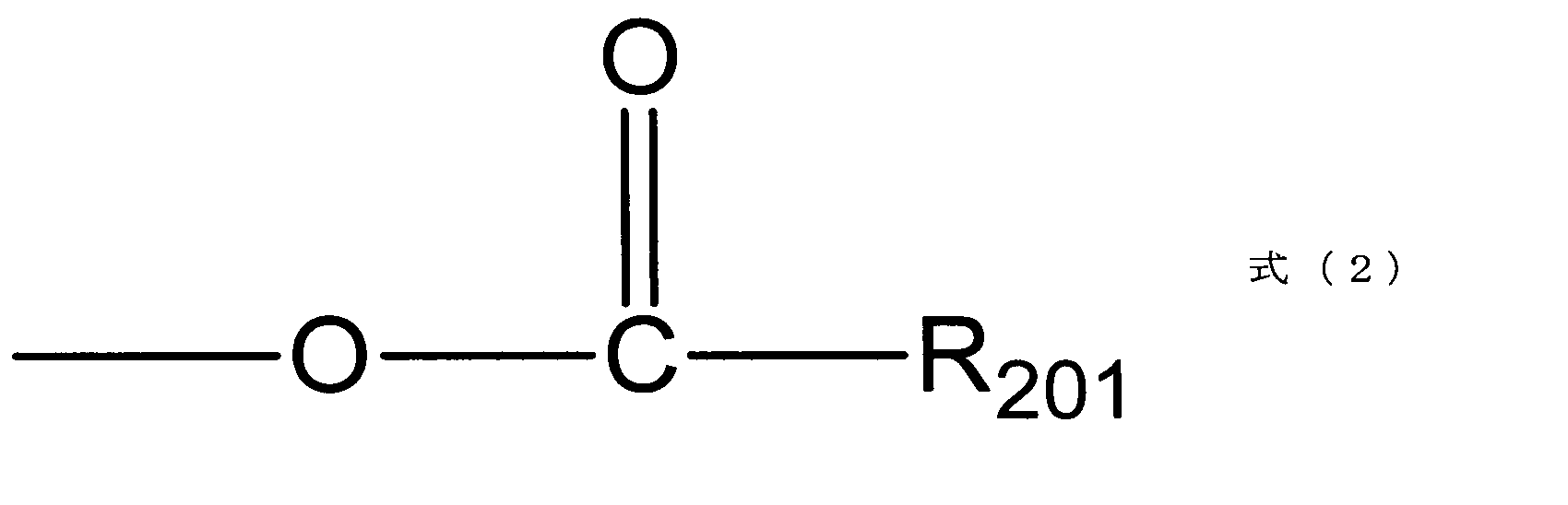
- the halogen-containing ester group is represented by the formula (2)
- the halogen-containing ether group is represented by the formula (3).
- n is an integer of 2 or more, and each of R 101 to R 106 is independent for each n. ].
- R 201 represents an alkyl group containing a halogen atom.
- R 301 represents an alkyl group containing a halogen atom.
- One of the embodiments is This is a separator for an electricity storage device in which at least a part of hydroxy groups on the fiber surface of a separator mainly composed of cellulose fibers is substituted with a halogen-containing ester group represented by the above formula (2).
- One of the embodiments is This is a separator for an electricity storage device in which at least a part of hydroxy groups on the fiber surface of a separator mainly composed of cellulose fibers is substituted with a halogen-containing ether group represented by the above formula (3).
- This is a power storage device separator in which a hydroxy group on the fiber surface of a separator containing inorganic fibers as a main component is substituted with a halogen-containing ester group represented by the formula (2).
- One of the embodiments is A separator for an electricity storage device in which a hydroxy group on a fiber surface of a separator mainly composed of inorganic fibers is substituted with a halogen-containing ether group represented by the formula (3).
- One of the embodiments is It is an electrical storage device containing the said separator for electrical storage devices, the negative electrode which has a negative electrode active material, and the electrolyte solution containing a supporting salt and a nonaqueous electrolytic solvent.
- One of the embodiments is A method for producing a separator for an electricity storage device, comprising contacting a cellulose separator containing cellulose as a main component with a solution containing a halogen-containing carboxylic acid represented by formula (4).
- R 401 represents an alkyl group containing a halogen atom.
- One of the embodiments is A method for producing a separator for an electricity storage device, comprising contacting a cellulose separator containing cellulose as a main component with a solution containing a halogen-containing alcohol represented by formula (5).
- R 501 represents an alkyl group containing a halogen atom.
- One of the embodiments is An inorganic material-containing separator containing inorganic fibers having a hydroxyl group on the surface is brought into contact with a solution containing a halogen-containing carboxylic acid represented by the formula (4).
- One of the embodiments is An inorganic material-containing separator containing inorganic fibers having a hydroxy group on the surface is brought into contact with a solution containing a halogen-containing carboxylic acid represented by the formula (5).
- One of the embodiments is It is an electrical storage device containing the separator for electrical storage devices manufactured by the said manufacturing method, the negative electrode which has a negative electrode active material, and the electrolyte solution containing a supporting salt and a nonaqueous electrolytic solvent.
- One of the embodiments is An electricity storage device having at least a negative electrode containing a negative electrode active material, an electrolyte solution containing a nonaqueous electrolytic solvent, and a separator,
- the negative electrode active material includes at least one of a metal capable of being alloyed with lithium (b) and a metal oxide (c) capable of inserting and extracting lithium ions
- the power storage device is characterized in that the separator is an inorganic material-containing separator mainly containing inorganic fibers.
- an electricity storage device in which a rise in battery temperature is suppressed can be provided.
- an electricity storage device including the electricity storage device separator according to the embodiment of the present invention has a high initial discharge capacity and high safety.
- FIG. 3 is a schematic cross-sectional view showing a structure of an electrode element included in a laminated laminate type secondary battery.
- 4 is an IR spectrum of a fluorine-containing alcohol cellulose separator in Production Example 2. It is IR spectrum of the cellulose separator before a process.
- One of the embodiments is a power storage device separator including the cellulose derivative represented by the formula (1) as described above.
- R 101 to R 106 each independently represents a hydroxy group, a halogen-containing ester group, or a halogen-containing ether group, and at least one of R 101 to R 106 is a halogen-containing ester group, or Halogen-containing ether group.
- the halogen-containing ester group is represented by the formula (2)
- the halogen-containing ether group is represented by the formula (3).
- n is an integer of 2 or more, and each of R 101 to R 106 is independent for each n. ].
- R 201 represents an alkyl group containing a halogen atom.
- R 301 represents an alkyl group containing a halogen atom.
- the alkyl group containing a halogen atom (hereinafter also abbreviated as a halogen-containing alkyl group) is preferably an alkyl group having 1 to 8 carbon atoms, and an alkyl group having 1 to 6 carbon atoms. And more preferably an alkyl group having 1 to 4 carbon atoms.
- the alkyl group includes a linear alkyl group, a branched alkyl group, or a cyclic alkyl group.
- the halogen atom is preferably a fluorine atom.
- an alkyl group containing a fluorine atom is also referred to as a fluorine-containing alkyl group.
- the halogen-containing alkyl group is preferably a fluorine-containing alkyl group.
- the fluorine-containing alkyl group include a perfluoromethyl group, a perfluoroethyl group, a perfluoropropyl group, and the like.
- the electricity storage device separator of the present embodiment may be formed by rinsing esterified or etherified cellulose fibers by, for example, a so-called papermaking method. Moreover, what formed the fiber of the esterified or etherified cellulose from the textile may be used. Moreover, the cellulose separator conventionally used as a separator can also be obtained by esterifying or etherifying. In this case, it is desirable to remove binders such as polyethyleneimine, sodium alginate, polyacrylamide and the like that may be used in the production of cellulose paper before or during treatment.
- binders such as polyethyleneimine, sodium alginate, polyacrylamide and the like that may be used in the production of cellulose paper before or during treatment.
- the thickness of the electricity storage device separator of the present embodiment is not particularly limited, but when one sheet is used alone, it is preferably 10 ⁇ m or more and 200 ⁇ m or less, and 20 ⁇ m or more and 100 ⁇ m or less. More preferably, it is further desirably 50 ⁇ m or less. It is because the intensity
- the porosity is preferably 30% or more and 99% or less. This is because, when the average pore diameter is 30% or more, the resistance of the membrane is reduced and the battery performance is improved. In order to further reduce the liquid resistance, it is desirable to be 55% or more. More preferably, it is 60% or more. Moreover, it is because generation
- the porosity can be determined from, for example, the true density and total volume of the material that is a raw material for the microporous membrane, and the weight and volume of the microporous membrane.
- the puncture strength in the film thickness direction is a value of a certain level or more.
- the separator containing cellulose fiber as a main component preferably contains 30% by mass or more of the constituent material, more preferably 50% or more, more preferably 70% or more, and more preferably 90% or more. Particularly preferred.
- the separator for an electricity storage device is obtained by bringing a cellulose separator mainly composed of cellulose into contact with a solution containing a halogen-containing carboxylic acid, and preferably by performing heat treatment in the contacted state. That is, the manufacturing method of this embodiment can also be grasped as a manufacturing method of a separator for an electricity storage device in which a cellulose separator mainly composed of cellulose is brought into contact with a solution containing a halogen-containing carboxylic acid.
- the halogen-containing carboxylic acid is represented by the formula (4).
- R 401 represents an alkyl group containing a halogen atom.
- the halogen-containing alkyl group is preferably an alkyl group having 1 to 8 carbon atoms, more preferably an alkyl group having 1 to 6 carbon atoms, and an alkyl group having 1 to 4 carbon atoms. More preferably it is.
- the alkyl group includes a linear alkyl group, a branched alkyl group, or a cyclic alkyl group.
- the halogen atom is preferably a fluorine atom.
- the halogen-containing alkyl group is preferably a fluorine-containing alkyl group. Examples of the fluorine-containing alkyl group include a perfluoromethyl group, a perfluoroethyl group, a perfluoropropyl group, and the like.
- halogen-containing carboxylic acid examples include trifluoroacetic acid, pentafluoropropionic acid, monochloroacetic acid, dichloroacetic acid, trichloroacetic acid, pentachloropropionic acid, dichloromonofluoroacetic acid, monochlorodifluoroacetic acid, monobromoacetic acid, dibromoacetic acid, tribromoacetic acid, Iodoacetic acid, 2-chloropropionic acid, 3-chloropropionic acid, 2-bromopropionic acid, 2-iodopropionic acid, 3-iodopropionic acid, 2,3-dichloropropionic acid, 2,3-dibromopropionic acid, 2 -Chloroacrylic acid, 2-chlorocrotonic acid and the like.
- a cellulose separator mainly composed of cellulose is brought into contact with a solution containing a halogen-containing carboxylic acid. Moreover, it heat-processes in the state which preferably made the cellulose separator contact the said solution.
- the solution preferably contains 70% or more of the halogen-containing carboxylic acid, more preferably 90% or more, and even more preferably 99% or more.
- the halogen-containing carboxylic acid an anhydride may be used in order to increase the reactivity.
- a pH adjusting agent, a catalyst, or the like can be added.
- the temperature of the solution in the heat treatment is preferably 50 ° C. or higher and 160 ° C. or lower, more preferably 60 ° C. or higher and 150 ° C. or lower, from the viewpoint that the hydroxy group of cellulose and the halogen-containing carboxylic acid easily react. More preferably, the temperature is 70 ° C. or higher and 140 ° C. or lower.
- the time for the heat treatment is not particularly limited, but is, for example, 30 minutes or more.
- the hydroxy group of cellulose is esterified by bringing the cellulose separator into contact with a solution containing a halogen-containing carboxylic acid, preferably by heating in the solution. That is, for example, when a cellulose separator is immersed in a halogen-containing carboxylic acid such as trifluoroacetic acid, the cellulose hydroxy group of the cellulose and the carboxy group of the halogen-containing carboxylic acid react to form a halogen-containing alkyl group. Is considered to be added to the cellulose separator via an ester group.
- a halogen-containing carboxylic acid such as trifluoroacetic acid
- a halogen-containing ester group is introduced into the surface of the cellulose fiber of the cellulose separator by treating with the halogen-containing carboxylic acid as described above.
- an appropriate amount of acid may be added to the solution in order to promote the reaction between the halogen-containing carboxylic acid and the hydroxyl group of cellulose.
- the acid include hydrochloric acid, sulfuric acid, concentrated sulfuric acid, phosphoric acid and the like.
- the pH of the solution is preferably from 1 to 8, more preferably from 3 to 7.
- the cellulose separator is not particularly limited, and any separator containing cellulose can be used without any particular problem.
- a known separator containing cellulose can be used.
- the cellulose separator may be a non-woven fabric made of a material other than cellulose in order to increase the strength as long as it contains cellulose.
- materials other than cellulose include resin materials such as polypropylene, polyethylene, polyethylene terephthalate (PET), polytetrafluoroethylene, polyvinylidene fluoride, polyimide, and polyamideimide.
- one or both surfaces of cellulose paper may be chemically modified or physically modified by spin coating or the like.
- a film made of a resin material such as polyethylene, polypropylene, polyethylene terephthalate, polytetrafluoroethylene, polyvinylidene fluoride, polyimide, polyamideimide, or a paper-like material laminated on cellulose paper should be used. You can also.
- the cellulose separator preferably contains 30% by mass or more of cellulose fibers in the constituent materials in order to maintain strength when immersed in the electrolytic solution. Moreover, when a cellulose fiber is contained 50 mass% or more, the internal short circuit of a battery can be suppressed more. More preferably, it is a nonwoven fabric in which cellulose fibers are contained in an amount of 70% by mass or more in the constituent materials. Moreover, it is preferable that a cellulose separator which has a cellulose as a main component contains a cellulose fiber as a main component.
- the solution can be removed by washing.
- the solvent used for washing include non-aqueous solvents such as chloroform, acetonitrile, and hexane.
- the thickness of the cellulose separator used for production is not particularly limited, but when one sheet is used alone, it is preferably 10 ⁇ m or more and 200 ⁇ m or less, more preferably 20 ⁇ m or more and 100 ⁇ m or less. Preferably, it is 50 ⁇ m or less. It is because the intensity
- the porosity of the cellulose separator used for production is desirably 30% or more and 99% or less. This is because, when the average pore diameter is 30% or more, the resistance of the membrane is reduced and the battery performance is improved. In order to further reduce the liquid resistance, it is desirable to be 55% or more. More preferably, it is 60% or more. Moreover, it is because generation
- the porosity can be determined from, for example, the true density and total volume of the material that is a raw material for the microporous membrane, and the weight and volume of the microporous membrane.
- the puncture strength in the film thickness direction is a value of a certain level or more.
- a halogen-containing carboxylic acid is added to a cellulose fiber and subjected to an esterification reaction by heat treatment, and a nonwoven fabric is formed using the obtained fiber.
- Cellulose fibers are preferably contained in 30% by mass or more of the constituent materials of the separator, more preferably 50% or more, further preferably 70% or more, and more preferably 90% or more. It is particularly preferable.
- the separator for an electricity storage device of this embodiment is obtained by bringing a cellulose separator mainly composed of cellulose fibers into contact with a solution containing a halogen-containing alcohol, and preferably heat-treating the contacted solution. That is, the manufacturing method of this embodiment can also be grasped as a manufacturing method of a separator for an electricity storage device in which a cellulose separator mainly composed of cellulose fibers is contacted with a solution containing a halogen-containing alcohol.
- Halogen-containing alcohol is represented by the formula (5).
- R 501 represents an alkyl group containing a halogen atom.
- the halogen-containing alkyl group is preferably an alkyl group having 1 to 8 carbon atoms, more preferably an alkyl group having 1 to 6 carbon atoms, and an alkyl group having 1 to 4 carbon atoms. More preferably it is.
- the alkyl group includes a linear alkyl group, a branched alkyl group, or a cyclic alkyl group.
- the halogen atom is preferably a fluorine atom.
- the halogen-containing alkyl group is preferably a fluorine-containing alkyl group. Examples of the fluorine-containing alkyl group include a perfluoromethyl group, a perfluoroethyl group, a perfluoropropyl group, and the like.
- halogen-containing alcohol examples include trifluoroethanol, pentafluoropropanol (2,2,3,3,3-pentafluoropropanol), trichloroethanol, pentachloropropanol, 2-fluoroethanol, 2-bromoethanol, 3- Examples include iodoethanol, 2,2-difluoroethanol, and 2,2-dichloroethanol.
- the cellulose separator which has a cellulose fiber as a main component is made to contact the solution containing halogen containing alcohol.
- the solution preferably contains 70% or more of a halogen-containing alcohol, more preferably 90% or more, and even more preferably 99% or more.
- concentration may be adjusted with a solvent such as water, and a pH adjusting agent, a catalyst, or the like may be added.
- the temperature of the solution in the heat treatment is preferably 50 ° C. or higher and 150 ° C. or lower, more preferably 60 ° C. or higher and 120 ° C. or lower, from the viewpoint that the hydroxy group of the cellulose fiber and the halogen-containing alcohol easily react. .
- the time for the heat treatment is not particularly limited, but is, for example, 30 minutes or more.
- the hydroxy group of the cellulose fiber is etherified by bringing the cellulose separator into contact with a solution containing a halogen-containing alcohol, preferably heating in the solution. That is, by subjecting the cellulose fiber to a hydroxy group of the halogen-containing alcohol by reacting the hydroxy group of the cellulose fiber with a heat treatment in a state where the cellulose separator is immersed in a halogen-containing alcohol such as trifluoroethanol, the halogen-containing alkyl group is converted into an ether group. It is thought that it is added to the cellulose separator via
- the halogen-containing ether group is introduced into the surface of the cellulose fiber of the cellulose separator by treating with the halogen-containing alcohol as described above.
- the same ones as described above can be used.
- drying treatment can be appropriately performed.
- the solution can be removed by washing.
- the solvent used for washing include non-aqueous solvents such as chloroform, acetonitrile, and hexane.
- the cellulose separator treated with the above-mentioned halogen-containing carboxylic acid may be used for further treatment with a halogen-containing alcohol.
- a cellulose separator treated with a halogen-containing alcohol may be used and further treated with an alcohol halogen-containing carboxylic acid.
- a method for producing a separator for an electricity storage device in which an inorganic material-containing separator containing an inorganic material having a hydroxy group on the surface is brought into contact with a solution containing at least a halogen-containing carboxylic acid or a halogen-containing alcohol will be described.
- a fluorine-containing carboxylic acid can be preferably used as the halogen-containing carboxylic acid
- a fluorine-containing alcohol can be preferably used as the halogen-containing alcohol.
- halogen-containing carboxylic acid or halogen-containing alcohol in the present embodiment those described above can be used.
- the inorganic material-containing separator contains inorganic fibers having a hydroxy group on the surface as a main component.
- the inorganic fiber include alumina fiber, carbon fiber, glass fiber, titanium oxide fiber, and boron oxide fiber.
- the inorganic fiber may be a fiber made of ceramic or a fiber made of an inorganic electrolyte material such as a lithium ion conductor. Of these, alumina fibers or glass fibers are preferably used. Examples of the glass fiber include microfiber wool, long fiber, and glass wool glass fiber.
- the inorganic material-containing separator may include particles made of an inorganic material (hereinafter also abbreviated as inorganic particles).
- the inorganic particles include alumina particles, silica particles, or carbon material particles, titanium oxide particles and boron oxide particles, quartz glass particles, silicon oxide particles, calcium oxide particles and magnesium oxide particles, potassium oxide particles, and sodium oxide. Examples thereof include particles, aluminum nitride particles, and silicon nitride particles. Among these, alumina particles or silica particles are preferable.
- the inorganic particles can be fixed in the inorganic fiber using, for example, a binder.
- inorganic particles may be contained in inorganic fibers.
- the inorganic material-containing separator may be used after surface treatment with a solution containing, for example, calcium fluoride, barium sulfate, barium fluoride, calcium salt, sodium salt, magnesium salt, potassium salt, amide sulfate, and the like.
- a solution containing, for example, calcium fluoride, barium sulfate, barium fluoride, calcium salt, sodium salt, magnesium salt, potassium salt, amide sulfate, and the like. aqueous solution (Sawada Chemical Co., Ltd .; Notburn) containing amide sulfate in a glass cloth (Sawada Chemical Co., Ltd .; non-combustible mesh) in which a glass fiber is woven.
- the separator surface-treated by spraying is used.
- the inorganic material-containing separator preferably has a shrinkage rate of 30% or less when held at 200 ° C. or higher for 10 seconds, and more preferably has a shrinkage rate of 10% or lower when held at 300 ° C. for 10 seconds. .
- reinforced mortar or concrete mixed with alkali-resistant glass fiber may be used as the inorganic material-containing separator.
- the inorganic material-containing separator can be obtained, for example, by forming the above-described inorganic fibers into a sheet shape, a film shape, a mesh shape, or a cloth shape.
- the inorganic fiber-containing separator can be obtained by intertwining the above-described inorganic fibers mechanically or using a chemical action to form a sheet or cloth. At this time, a binder may be added in order to make the inorganic fibers adhere more closely.
- the inorganic material-containing separator can also be obtained by weaving inorganic fibers twisted into a thread shape to form a woven fabric, cloth, film, sheet, mesh, or cloth.
- the nonwoven fabric and thin film glass cloth made from glass fiber are mentioned, for example.
- a woven fabric is desirable because the amount of the binder is small and a thin film having a thickness of 50 ⁇ m or less can be easily formed.
- heat treated for several seconds using a gas burner or the like, or dried in a vacuum of 100 ° C or higher What was processed is good also as an inorganic material content separator.
- the thermal contraction rate of the knitted fabric by this heat treatment or heat drying treatment is preferably 20% or less of the original size, and more preferably 5% or less.
- Inorganic fibers may be used alone or in combination of two or more.
- the inorganic material-containing separator preferably contains inorganic fibers having a hydroxy group on the surface as a main component.
- the inorganic material-containing separator preferably has, for example, a configuration containing glass fiber as a main component and silica particles and alumina particles.
- the inorganic material-containing separator preferably contains 30% by mass or more of the constituent components of the separator, more preferably contains 50% by mass or more, more preferably contains 70% or more, and particularly preferably contains 90% or more. preferable.
- the inorganic material-containing separator may be one in which the inorganic fiber is used as a main component, and the strength of the inorganic fiber is increased with an organic or inorganic binder.
- the amount of the organic binder is preferably 20% by mass or less in the constituent components of the inorganic material-containing separator, and more preferably 10% by mass or less from the viewpoint of improving heat resistance.
- the shape of the inorganic material-containing separator is not particularly limited, but is, for example, paper, mesh, or plate.
- a mesh shape in which inorganic fibers are woven like a knitted fabric is desirable.
- the weaving method include plain weave, twill weave, satin weave, leopard weave, imitation weave, broken oblique crest weave and double weave.
- the thickness of the inorganic material-containing separator used for production is not particularly limited, but when one sheet is used alone, it is preferably 10 ⁇ m or more and 300 ⁇ m or less, more preferably 20 ⁇ m or more and 100 ⁇ m or less. Preferably, it is 50 ⁇ m or less. It is because the intensity
- the porosity of the inorganic material-containing separator used for production is desirably 30% or more and 99% or less. This is because, when the average pore diameter is 30% or more, the resistance of the membrane is reduced and the battery performance is improved. In order to further reduce the liquid resistance, it is desirable to be 55% or more. More preferably, it is 60% or more. Moreover, it is because generation
- the porosity can be determined from, for example, the true density and total volume of the material that is a raw material for the microporous membrane, and the weight and volume of the microporous membrane.
- the puncture strength in the film thickness direction is a value of a certain level or more.
- One embodiment of the present invention is a method for manufacturing a separator for an electricity storage device in which an inorganic material-containing separator containing inorganic fibers having a hydroxy group on the surface is brought into contact with a solution containing a halogen-containing carboxylic acid or a halogen-containing alcohol.
- the halogen-containing carboxylic acid or halogen-containing alcohol is preferably a fluorine-containing carboxylic acid or a fluorine-containing alcohol.
- the manufacturing method of this embodiment can also be grasped as a manufacturing method of a separator for an electricity storage device in which an inorganic material-containing separator is brought into contact with a solution containing a halogen-containing carboxylic acid or a halogen-containing alcohol. Moreover, it is preferable to heat-process in the state which made the inorganic material containing separator contact this solution.
- the solution contains at least a halogen-containing carboxylic acid or halogen-containing alcohol and water, but may contain an acid in addition to these from the viewpoint of promoting the reaction.
- the acid added to the reaction system is not particularly limited, and examples thereof include concentrated sulfuric acid, sulfuric acid, hydrochloric acid, and phosphoric acid.
- the pH of the solution is preferably from 1 to 8, more preferably from 3 to 7.
- an inorganic material-containing separator is immersed in 20 parts by mass of trifluoroacetic acid, and then heated and controlled at 60 ° C. Thereafter, 10 parts by mass of concentrated sulfuric acid is added to trifluoroacetic acid, and heat treatment is performed with stirring for 1 hour so that the temperature of the solution becomes 60 ° C. Thereafter, it is washed with a non-aqueous solvent such as chloroform.
- the solution can be removed by washing.
- the solvent used for washing include non-aqueous solvents such as chloroform, acetonitrile, and hexane.
- the above-described treatment using the halogen-containing carboxylic acid or the halogen-containing alcohol is performed on the inorganic fiber, and the inorganic fiber after the treatment is used to form a cloth shape, a sheet shape, a mesh shape, a film shape, or a cloth shape. By doing so, you may obtain the separator which concerns on this embodiment.
- a halogen-containing carboxylic acid or a halogen-containing alcohol is used for the inorganic material-containing separator, and an acid such as concentrated sulfuric acid is added and heated, whereby the hydroxy group of the inorganic material-containing separator is changed to a halogen-containing carboxylic acid residue or a halogen-containing alcohol.
- a residue may be substituted.
- the separator for an electricity storage device manufactured by the above method at least a part of the hydroxy group on the surface of the inorganic fiber of the inorganic material-containing separator mainly containing inorganic fiber is substituted with a halogen-containing ester group or a halogen-containing ether group.
- a halogen-containing ester group or a halogen-containing ether group is the same as described above.
- the secondary battery according to the present embodiment is a secondary battery including the power storage device separator according to the present embodiment.
- the shape of the secondary battery may be any of a cylindrical type, a flat wound square type, a laminated square type, a coin type, a flat wound laminate type, and a laminated laminate type.
- the shape of the secondary battery is preferably a laminated laminate type from the viewpoint that the separator is not easily broken.
- a laminated laminate type secondary battery will be described.
- FIG. 1 is a schematic cross-sectional view showing a structure of an electrode element included in a laminated laminate type secondary battery.
- This electrode element is formed by alternately stacking a plurality of positive electrodes c and a plurality of negative electrodes a with a separator b interposed therebetween.
- the positive electrode current collector e of each positive electrode c is welded to and electrically connected to each other at an end portion not covered with the positive electrode active material, and a positive electrode terminal f is welded to the welded portion.
- the negative electrode current collector d of each negative electrode a is welded and electrically connected to each other at an end portion not covered with the negative electrode active material, and a negative electrode terminal g is welded to the welded portion.
- the electrode element having such a planar laminated structure does not have a portion with a small R (a region close to the winding core of the wound structure), the electrode element associated with charge / discharge is compared with an electrode element having a wound structure.
- the volume change That is, it is effective as an electrode element using an active material that easily causes volume expansion.
- the lithium secondary battery of this embodiment includes a negative electrode having a negative electrode active material.
- the negative electrode active material can be bound on the negative electrode current collector by a negative electrode binder.
- the negative electrode active material in the present embodiment is not particularly limited.
- a metal (a) that can be alloyed with lithium a metal oxide (b) that can occlude and release lithium ions, or occlude lithium ions, A carbon material (c) that can be released may be included.
- the negative electrode active material in the present embodiment is not particularly limited, and for example, a carbon material (a) that can occlude and release lithium ions, a metal that can be alloyed with lithium (b), or occlude and release lithium ions.
- the metal oxide (c) etc. which can be mentioned.
- Examples of the carbon material (a) include carbon, amorphous carbon, diamond-like carbon, carbon nanotube, or a composite thereof.
- carbon with high crystallinity has high electrical conductivity, and is excellent in adhesiveness and voltage flatness with a negative electrode current collector made of a metal such as copper.
- amorphous carbon having low crystallinity has a relatively small volume expansion, it has a high effect of relaxing the volume expansion of the entire negative electrode, and deterioration due to non-uniformity such as crystal grain boundaries and defects hardly occurs.
- the metal (b) examples include Al, Si, Pb, Sn, In, Bi, Ag, Ba, Ca, Hg, Pd, Pt, Te, Zn, La, or alloys of two or more thereof. It is done. Moreover, you may use these metals or alloys in mixture of 2 or more types. These metals or alloys may contain one or more non-metallic elements.
- the negative electrode active material preferably includes tin or silicon, and more preferably includes silicon. This is because the phosphoric acid residue contained in the cellulose for an electricity storage device of the present embodiment hardly reacts with tin or silicon, and thus can suppress an increase in irreversible capacity.
- the metal oxide (c) examples include silicon oxide, aluminum oxide, tin oxide, indium oxide, zinc oxide, lithium oxide, and composites thereof.
- tin oxide or silicon oxide is included as a negative electrode active material, and it is more preferable that silicon oxide is included. This is because silicon oxide is relatively stable and hardly causes a reaction with other compounds.
- one or more elements selected from nitrogen, boron, and sulfur may be added to the metal oxide (c), for example, 0.1 to 5% by mass. By carrying out like this, the electrical conductivity of a metal oxide (c) can be improved.
- the metal oxide (c) has an amorphous structure.
- the metal oxide (c) having an amorphous structure can suppress volume expansion of the carbon material (a) and the metal (b) which are other negative electrode active materials. Although this mechanism is not clear, it is presumed that the formation of a film on the interface between the carbon material (a) and the electrolytic solution has some influence due to the amorphous structure of the metal oxide (c).
- the amorphous structure is considered to have relatively few elements due to non-uniformity such as crystal grain boundaries and defects.
- the metal oxide (c) does not have an amorphous structure, a peak specific to the metal oxide (c) is observed, but all or part of the metal oxide (c) is amorphous. In the case of having a structure, the intrinsic peak of the metal oxide (c) is broad and observed.
- the negative electrode active material in the present embodiment includes a carbon material (a) that can occlude and release lithium ions, a metal (b) that can be alloyed with lithium, and a metal oxide (c) that can occlude and release lithium ions. It is preferable to contain.
- the metal (b) is preferably silicon, and the metal oxide (c) is preferably silicon oxide. That is, the negative electrode active material is preferably composed of a composite of silicon, silicon oxide, and a carbon material (hereinafter also referred to as Si / SiO / C composite).
- the negative electrode active material in which lithium is chemically and thermally doped in advance.
- the negative electrode active material in thermal doping, can be doped with lithium by bringing the negative electrode active material into contact with lithium metal and warming the whole.
- the Si / SiO / C composite it is preferable that all or part of silicon is dispersed in silicon oxide.
- silicon oxide By dispersing at least a part of silicon in silicon oxide, volume expansion as a whole of the negative electrode can be further suppressed, and decomposition of the electrolytic solution can also be suppressed.
- all or part of silicon is dispersed in silicon oxide because transmission electron microscope observation (general TEM observation) and energy dispersive X-ray spectroscopy measurement (general EDX measurement) are used in combination. This can be confirmed. Specifically, the cross section of a sample containing silicon particles can be observed, and the oxygen concentration of silicon particles dispersed in silicon oxide can be measured to confirm that it is not an oxide.
- the Si / SiO / C composite for example, all or part of silicon oxide has an amorphous structure, and all or part of silicon is dispersed in silicon oxide.
- a Si / SiO / C composite can be produced, for example, by a method disclosed in Patent Document 3 (Japanese Patent Laid-Open No. 2004-47404). That is, the Si / SiO / C composite can be obtained, for example, by performing CVD treatment of silicon oxide in an atmosphere containing an organic gas such as methane gas.
- the Si / SiO / C composite obtained by such a method has a form in which the surface of particles made of silicon oxide containing silicon is coated with carbon. Silicon is nanoclustered in silicon oxide.
- the ratio of the carbon material, silicon and silicon oxide is not particularly limited.
- the carbon material is preferably 2% by mass or more and 50% by mass or less, and more preferably 2% by mass or more and 30% by mass or less with respect to the Si / SiO / C composite.
- Silicon is preferably 5% by mass or more and 90% by mass or less, and more preferably 20% by mass or more and 50% by mass or less with respect to the Si / SiO / C composite.
- Silicon oxide is preferably 5% by mass or more and 90% by mass or less, and more preferably 40% by mass or more and 70% by mass or less with respect to the Si / SiO / C composite.
- the Si / SiO / C composite can be made of a mixture of carbon material, silicon and silicon oxide.
- the Si / SiO / C composite can be obtained by mixing particles of carbon materials, silicon, and silicon oxide.
- the average particle diameter of silicon can be configured to be smaller than the average particle diameter of the carbon material and the average particle diameter of silicon oxide. In this way, silicon with a small volume change during charge and discharge has a relatively small particle size, and carbon materials and silicon oxide with a large volume change have a relatively large particle size. Is more effectively suppressed.
- lithium is occluded and released in the order of large-diameter particles, small-diameter particles, and large-diameter particles during the charge / discharge process. This also suppresses the occurrence of residual stress and residual strain. Is done.
- the average particle diameter of silicon can be, for example, 20 ⁇ m or less, and is preferably 15 ⁇ m or less.
- the binder for the negative electrode is not particularly limited.
- polyvinylidene fluoride, vinylidene fluoride-hexafluoropropylene copolymer, vinylidene fluoride-tetrafluoroethylene copolymer, styrene-butadiene copolymer Rubber, polytetrafluoroethylene, polypropylene, polyethylene, polyimide, polyamideimide, polyacrylic acid, or the like can be used.
- polyimide or polyamideimide is preferred because of its high binding properties.
- the amount of the binder for the negative electrode to be used is preferably 5 to 25 parts by mass with respect to 100 parts by mass of the negative electrode active material from the viewpoints of “sufficient binding force” and “high energy” which are in a trade-off relationship. .
- the negative electrode current collector aluminum, nickel, stainless steel, chromium, copper, silver, and alloys thereof are preferable in view of electrochemical stability.
- the shape include foil, flat plate, and mesh.
- the negative electrode can be produced by forming a negative electrode active material layer containing a negative electrode active material and a negative electrode binder on a negative electrode current collector.
- Examples of the method for forming the negative electrode active material layer include a doctor blade method, a die coater method, a CVD method, and a sputtering method.
- a thin film of aluminum, nickel, or an alloy thereof may be formed by a method such as vapor deposition or sputtering to form a negative electrode.
- the positive electrode is formed, for example, by binding a positive electrode active material so as to cover the positive electrode current collector with a positive electrode binder.
- manganese having a layered structure such as LiMnO 2 , LixMn 2 O 4 (0 ⁇ x ⁇ 2), Li 2 MnO 3 , LixMn 1.5 Ni 0.5 O 4 (0 ⁇ x ⁇ 2), etc.
- Lithium oxalate or lithium manganate having a spinel structure LiCoO 2 , LiNiO 2 or a part of these transition metals replaced with other metals; specific such as LiNi 1/3 Co 1/3 Mn 1/3 O 2 Lithium transition metal oxides with less than half of the transition metals; those lithium transition metal oxides with an excess of Li over the stoichiometric composition; those having an olivine structure such as LiFePO 4 .
- these metal oxides were partially substituted with Al, Fe, P, Ti, Si, Pb, Sn, In, Bi, Ag, Ba, Ca, Hg, Pd, Pt, Te, Zn, La, etc. Materials can also be used.
- a positive electrode active material can be used individually by 1 type or in combination of 2 or more types.
- radical materials or the like can be used as the positive electrode active material.
- the positive electrode binder the same as the negative electrode binder can be used.
- polyvinylidene fluoride is preferable from the viewpoint of versatility and low cost.
- the amount of the positive electrode binder to be used is preferably 2 to 15 parts by mass with respect to 100 parts by mass of the positive electrode active material from the viewpoints of “sufficient binding force” and “high energy” which are in a trade-off relationship. .
- the positive electrode current collector the same as the negative electrode current collector can be used.
- a conductive auxiliary material may be added to the positive electrode active material layer containing the positive electrode active material for the purpose of reducing impedance.
- the conductive auxiliary material include carbonaceous fine particles such as graphite, carbon black, and acetylene black.
- the electrolytic solution used in the present embodiment is not particularly limited, but includes, for example, a supporting salt and a nonaqueous electrolytic solvent.
- An aprotic organic solvent such as aliphatic carboxylic acid esters.
- Nonaqueous electrolytic solvents include ethylene carbonate (EC), propylene carbonate (PC), butylene carbonate (BC), vinylene carbonate (VC), dimethyl carbonate (DMC), diethyl carbonate (DEC), ethyl methyl carbonate (MEC), Cyclic or chain carbonates such as propyl carbonate (DPC) are preferred.
- a non-aqueous electrolysis solvent can be used individually by 1 type or in combination of 2 or more types.
- non-aqueous electrolytic solvents include, for example, ethylene sulfite (ES), propane sultone (PS), butane sultone (BS), dioxathilane-2,2-dioxide (DD), sulfolene, 3-methyl Sulfolen, sulfolane (SL), succinic anhydride (SUCAH), propionic anhydride, acetic anhydride, maleic anhydride, diallyl carbonate (DAC), diphenyl disulfide (DPS), dimethoxyethane (DME), dimethoxymethane (DMM) , Diethoxyethane (DEE), ethoxymethoxyethane, dimethyl ether, methyl ethyl ether, methyl propyl ether, ethyl propyl ether, dipropyl ether, methyl butyl ether, diethyl ether, phenyl methyl ether, Rahidorofuran (THF),
- the nonaqueous electrolytic solvent preferably contains a fluorinated carbonate.
- the fluorinated carbonate includes cyclic and chain ones, and specific examples include fluorinated cyclic carbonates and fluorinated chain carbonates. Moreover, it is preferable that it is a fluorinated cyclic carbonate.
- the fluorinated cyclic carbonate is not particularly limited, and ethylene carbonate, propylene carbonate, vinylene carbonate, a compound obtained by partially fluorinating vinyl ethylene carbonate, and the like can also be used. More specifically, for example, 4-fluoro-1,3-dioxolane-2-one (fluoroethylene carbonate, hereinafter also referred to as FEC), (cis or trans) 4,5-difluoro-1,3-dioxolane-2 -One, 4,4-difluoro-1,3-dioxolan-2-one, 4-fluoro-5-methyl-1,3-dioxolan-2-one and the like can be used. Among these, fluoroethylene carbonate is preferable.
- R a , R b , R c , and R d are each independently a hydrogen atom, a fluorine atom, or a fluorine-containing alkyl group, and R a , R b , R c , and R d At least one of is a fluorine atom or a fluorine-containing alkyl group.
- the fluorine-containing alkyl group preferably has at least one fluorine atom, and all the hydrogen atoms of the alkyl group are substituted with fluorine atoms.
- the fluorine-containing alkyl group preferably includes a linear or branched chain and has 1 to 5 carbon atoms.
- the compound which substituted the hydrogen of one part or all part of dimethyl carbonate, diethyl carbonate, ethyl methyl carbonate, dipropyl carbonate, and methylpropyl carbonate can also be used.
- bis (fluoroethyl) carbonate, 3-fluoropropyl methyl carbonate, 3,3,3-trifluoropropyl methyl carbonate and the like can be mentioned.
- fluorinated chain carbonate there is a compound overlapping the above description, but a compound represented by the following formula (7) is preferably exemplified.
- R y and R z are each independently a hydrogen atom or a fluorine-containing alkyl group, and at least one of R y and R z is a fluorine-containing alkyl group.
- the fluorine-containing alkyl group preferably has at least one fluorine atom, and all the hydrogen atoms of the alkyl group are substituted with fluorine atoms.
- the fluorine-containing alkyl group preferably includes a linear or branched chain and has 1 to 5 carbon atoms.
- the content of the fluorinated carbonate is preferably 0.01% by mass or more and 50% by mass or less in the nonaqueous electrolytic solvent.
- the content of the fluorinated carbonate is preferably 0.1% by mass or more and 30% by mass or less in the electrolytic solution, and more preferably 1% by mass or more and 10% by mass or less.
- the non-aqueous electrolytic solvent preferably contains a carbonate other than the fluorinated carbonate (hereinafter also referred to as non-fluorinated carbonate) and a fluorinated carbonate.
- a carbonate other than the fluorinated carbonate hereinafter also referred to as non-fluorinated carbonate
- fluorinated carbonate By using non-fluorinated carbonate, the ion dissociation property of the electrolytic solution is improved, and the viscosity of the electrolytic solution is lowered. Therefore, ion mobility can be improved.
- Non-fluorinated carbonates include chain and cyclic (non-fluorinated) as described above.
- the non-aqueous electrolytic solvent preferably contains non-fluorinated carbonate as a main solvent, and the non-aqueous electrolytic solvent is 70 to 99.9% by mass of non-fluorinated carbonate and 0.1 to 15% by mass of fluorinated carbonate. And more preferably.
- the nonaqueous electrolytic solvent preferably contains a phosphate ester compound as a main solvent, and the nonaqueous electrolytic solvent contains 70 to 99.9% by mass of a phosphate ester compound and 0.1 to 15% by mass of a fluorinated carbonate. It is more preferable to contain.
- the content of the phosphate ester compound in the nonaqueous electrolytic solvent is more preferably 85 to 99% by mass, and still more preferably 90 to 98% by mass.
- the content of the fluorinated carbonate compound in the nonaqueous electrolytic solvent is more preferably 0.2 to 13% by mass, and further preferably 1 to 10% by volume.
- Examples of the phosphate ester compound include a compound represented by the following formula (8).
- Rs, Rt and Ru are each independently a substituted or unsubstituted alkyl group, alkenyl group, aryl group or cycloalkyl group, and any one of Rs, Rt and Ru Or you may form the cyclic structure which all couple
- the alkyl group is preferably an alkyl group having 1 to 18 carbon atoms, more preferably an alkyl group having 1 to 12 carbon atoms, and further preferably an alkyl group having 1 to 6 carbon atoms.
- the alkyl group includes a linear alkyl group, a branched alkyl group, or a cyclic alkyl group.
- the aryl group is preferably an aryl group having 6 to 18 carbon atoms, more preferably an aryl group having 6 to 12 carbon atoms, and further preferably an aryl group having 6 to 10 carbon atoms. .
- the alkenyl group is preferably an alkenyl group having 2 to 18 carbon atoms in total, more preferably an alkenyl group having 2 to 12 carbon atoms in total, and further preferably an alkenyl group having 2 to 6 carbon atoms in total.
- Preferred examples of the substituent include a halogen atom.
- a halogen atom a chlorine atom, a fluorine atom, or a bromine atom etc. are mentioned, for example.
- phosphate ester compound examples include trimethyl phosphate, triethyl phosphate, tripropyl phosphate, tributyl phosphate, tripentyl phosphate, trihexyl phosphate, triheptyl phosphate, trioctyl phosphate, dimethylethyl phosphate, and phosphoric acid.
- Alkyl phosphate compounds such as dimethylmethyl (DMMP), dimethylethyl phosphate, diethylmethyl phosphate; aryl phosphate compounds such as triphenyl phosphate; methyl ethylene phosphate, ethyl ethylene phosphate (EEP), ethyl phosphate Phosphoric acid ester compounds having a cyclic structure such as butylene; Tris (trifluoromethyl) phosphate, Tris (pentafluoroethyl) phosphate, Tris (2,2,2-trifluoroeth) l) Alkyl halides such as phosphate, Tris (2,2,3,3-tetrafluoropropyl) phosphate, Tris (3,3,3-trifluoropropylate) phosphate, Tris (2,2,3,3,3-pentafluoropropyl) phosphate A phosphate ester compound is mentioned.
- DMMP dimethylethyl phosphate
- trialkyl phosphate compounds such as trimethyl phosphate, triethyl phosphate, tripropyl phosphate, tributyl phosphate, tripentyl phosphate, trihexyl phosphate, triheptyl phosphate, trioctyl phosphate are used as the phosphate ester compound. It is preferable.
- a phosphate ester compound can be used individually by 1 type or in combination of 2 or more types.
- the electrolytic solution may be mixed with a fluorinated ether having an R v1 —O—R v2 structure (R v1 and R v2 are each an alkyl group or a fluorine alkyl group), an ionic liquid, phosphazene, or the like.
- the supporting salt is not particularly limited, for example, LiPF 6, LiI, LiBr, LiCl, LiAsF 6, LiAlCl 4, LiClO 4, LiBF 4, LiSbF 6, LiCF 3 SO 3, LiC 4 F 9 SO 3 , LiN (FSO 2 ) 2 , LiN (CF 3 SO 2 ) 2 , LiN (C 2 F 5 SO 2 ) 2 , LiN (CF 3 SO 2 ) (C 2 F 5 SO 2 ), LiN (CF 3 SO 2 ) (C 4 F 9 SO 2 ), cyclic LiN (CF 2 SO 2 ) 2 , LiN (CF 2 SO 2 ) 2 (CF 2 ) and the like.
- Examples of the supporting salt include LiPF 5 (CF 3 ), LiPF 5 (C 2 F 5 ), and LiPF 5 (C 3 F 7 ) in which at least one fluorine atom of LiPF 6 is substituted with a fluorinated alkyl group. , LiPF 4 (CF 3 ) 2 , LiPF 4 (CF 3 ) (C 2 F 5 ), LiPF 3 (CF 3 ) 3 and the like.
- examples of the lithium salt include a salt made of the compound represented by the formula (9).
- R 1 , R 2 and R 3 in the formula (9) are selected from the group consisting of a halogen atom and a fluorinated alkyl group, and may be different or the same.
- Specific examples of the compound represented by the formula (6) include LiC (CF 3 SO 2 ) 3 and LiC (C 2 F 5 SO 2 ) 3 .
- Supporting salt can be used alone or in combination of two or more.
- the concentration of the lithium salt is not particularly limited, but is, for example, 0.01 M (mol / L) or more and 3 M (mol / L) or less in the electrolytic solution. Moreover, it is preferable that the density
- the amount of the electrolytic solution is desirably adjusted as appropriate based on the porosity of the positive electrode, the negative electrode, and the separator.
- the amount of the electrolytic solution is preferably 0.2 or more and 2.0 or less, and preferably 0.5 or more and 1.5 or less, when 1.0 is the sum of the void volume of the positive electrode, the negative electrode, and the separator. More preferably. Further, from the viewpoint of facilitating further suppression of gas generation at a high temperature, the amount of the electrolytic solution is more preferably 1.2 or less, and particularly preferably 1.0 or less.
- the exterior body can be appropriately selected as long as it is stable to the electrolytic solution and has a sufficient water vapor barrier property.
- a laminated laminate type secondary battery a laminate film made of aluminum, silica-coated polypropylene, polyethylene, or the like can be used as the outer package.
- an aluminum laminate film from the viewpoint of suppressing volume expansion.
- the separator for an electricity storage device of this reference embodiment can be preferably applied to the configuration of the secondary battery described in the above embodiment.
- the present invention can be applied to a capacitor or the like.
- One of the embodiments is An electricity storage device having at least a negative electrode containing a negative electrode active material, an electrolyte solution containing a nonaqueous electrolytic solvent, and a separator,
- the negative electrode active material includes at least one of a metal capable of being alloyed with lithium (b) and a metal oxide (c) capable of inserting and extracting lithium ions
- the power storage device is characterized in that the separator is an inorganic material-containing separator mainly containing inorganic fibers.
- the metal (b) is preferably silicon.
- the metal oxide (c) is preferably silicon oxide.
- the negative electrode active material is more preferably composed of a composite of silicon, silicon oxide and a carbon material (hereinafter also referred to as Si / SiO / C composite).
- the non-aqueous electrolytic solvent preferably contains the phosphate compound as a main solvent.
- the content of the phosphate ester compound in the nonaqueous electrolytic solvent is, for example, 60% by mass or more, preferably 70% by mass or more, more preferably 80% by mass or more, and 90% by mass or more. More preferably it is.
- the nonaqueous electrolytic solvent more preferably contains 70 to 99.9% by mass of a phosphoric ester compound and 0.1 to 15% by mass of the fluorinated carbonate.
- the content of the phosphate ester compound in the nonaqueous electrolytic solvent is more preferably 85 to 99% by mass, and still more preferably 90 to 98% by mass.
- the content of the fluorinated carbonate compound in the nonaqueous electrolytic solvent is more preferably 0.2 to 13% by mass, and further preferably 1 to 10% by volume.
- inorganic material-containing separator those described above can be used.
- the fluorine-containing alcohol cellulose separator was washed with chloroform and sufficiently vacuum-dried, and then measured by IR.
- the IR spectrum is shown in FIG.
- the IR spectrum of the cellulose separator before the treatment with the fluorine-containing alcohol is also shown in FIG.
- the IR measurement was performed by transmission measurement using an apparatus manufactured by JASCO Corporation with a resolution of 4 cm ⁇ 1 and a scan count of 500 times.
- a separator made of polyethylene (manufactured by Celgard, film thickness: 23 ⁇ m, porosity 50%) was similarly subjected to a thermal stability test to obtain a thermal contraction rate (Table 1).
- the fluorine-containing carboxylate cellulose separator and the fluorine-containing alcohol cellulose separator have a low thermal shrinkage and high thermal stability in a high temperature environment as compared with the polyethylene separator.
- Example 1 Performance evaluation of secondary battery> Next, a secondary battery was prepared using a fluorine-containing carboxylate cellulose separator.
- a silicon / silicon oxide / carbon composite (hereinafter also referred to as Si / SiO / C composite) was obtained by performing CVD treatment at 1150 ° C. for 6 hours in an atmosphere containing methane gas.
- the Si / SiO / C composite had a form in which the surface of particles composed of silicon and silicon oxide was coated with carbon. Silicon was nanoclustered in silicon oxide.
- the mass ratio of Si / SiO / C was adjusted to be approximately 29/61/10.
- the negative electrode slurry was applied to a copper foil having a thickness of 10 ⁇ m, dried, and further subjected to a heat treatment in a nitrogen atmosphere at 300 ° C. to produce a negative electrode.
- 3 layers of the obtained positive electrode and 4 layers of the negative electrode were alternately stacked with the fluorine-containing cellulose carboxylate separator interposed therebetween.
- the ends of the positive electrode current collector that is not covered with the positive electrode active material and the negative electrode current collector that is not covered with the negative electrode active material are welded, and the positive electrode terminal made of aluminum and the negative electrode terminal made of nickel are further welded to the welded portions. Were respectively welded to obtain an electrode element having a planar laminated structure.
- electrolytic solution a solution obtained by dissolving LiPF 6 as a supporting salt at a concentration of 1 mol / L in a nonaqueous electrolytic solvent composed of EC: DEC (30:70) was used.
- the electrode element was wrapped with an aluminum laminate film as an exterior body, an electrolyte solution was poured into the inside, and then sealed while reducing the pressure to 0.1 atm to prepare a secondary battery.
- the initial charge capacity of the secondary battery produced as described above was measured.
- the initial charge / discharge conditions were 0.2 C current, 20 V environment, 4.2 V upper limit, and 2.5 V lower limit.
- Table 2 shows the measured discharge capacity.
- one layer of positive electrode and one layer of negative electrode were disposed via a fluorine-containing carboxylic acid cellulose separator, and an aluminum laminate cell was prepared by injecting an electrolytic solution. After conditioning the manufactured cell, it was charged to an upper limit voltage of 4.3 V with a current of 0.2 C. The charged cell was impacted by dropping a 5 kg weight from above at a height of 50 cm. After impacting the cell, the temperature of the cell was measured with a thermocouple attached to the outside of the cell. The cell rising temperature is calculated from the maximum temperature reached after the impact test and the cell temperature before the impact test, and is shown in Table 2.
- Example 2 A secondary battery and a cell were prepared and evaluated in the same manner as in Example 1 except that EC: DEC (30:70) was mixed with 5% by mass of fluoroethylene carbonate as the nonaqueous electrolytic solvent. did.
- Example 3 A secondary battery and a cell were prepared and evaluated in the same manner as in Example 1 except that TEP (triethyl phosphate) mixed with 2% by mass of fluoroethylene carbonate was used as the nonaqueous electrolytic solvent.
- TEP triethyl phosphate
- Example 4 Secondary batteries and cells were prepared and evaluated in the same manner as in Example 1 except that TEP (triethyl phosphate) mixed with 5% by mass of fluoroethylene carbonate was used as the nonaqueous electrolytic solvent.
- TEP triethyl phosphate
- Example 5 A secondary battery and a cell were prepared and evaluated in the same manner as in Example 1 except that TEP (triethyl phosphate) mixed with 10% by mass of fluoroethylene carbonate was used as the nonaqueous electrolytic solvent.
- TEP triethyl phosphate
- Example 6 A secondary battery and a cell were prepared and evaluated in the same manner as in Example 1 except that the above-described fluorine-containing alcohol cellulose separator was used instead of the fluorine-containing carboxylate cellulose separator.
- Example 7 A secondary battery and a cell were prepared and evaluated in the same manner as in Example 6 except that EC: DEC (30:70) was mixed with 5% by mass of fluoroethylene carbonate as the nonaqueous electrolytic solvent. .
- Example 8 A secondary battery and a cell were prepared and evaluated in the same manner as in Example 6 except that TEP (triethyl phosphate) mixed with 2% by mass of fluoroethylene carbonate was used as the nonaqueous electrolytic solvent.
- TEP triethyl phosphate
- Example 9 A secondary battery and a cell were prepared and evaluated in the same manner as in Example 6 except that TEP (triethyl phosphate) mixed with 5% by mass of fluoroethylene carbonate was used as the nonaqueous electrolytic solvent.
- TEP triethyl phosphate
- Example 10 A secondary battery and cell were prepared and evaluated in the same manner as in Example 6 except that TEP (triethyl phosphate) mixed with 10% by mass of fluoroethylene carbonate was used as the nonaqueous electrolytic solvent.
- TEP triethyl phosphate
- Example 11 A secondary battery and a cell were prepared and evaluated in the same manner as in Example 8 except that the fluorine-containing carboxylic acid inorganic material separator treated as described above was used instead of the fluorine-containing carboxylic acid cellulose separator.
- Example 12 A secondary battery and a cell were prepared and evaluated in the same manner as in Example 12 except that the fluorine-containing alcohol inorganic material separator treated as described above was used instead of the fluorine-containing inorganic carboxylate material separator.
- Example 13 A secondary battery and a cell were prepared and evaluated in the same manner as in Example 11 except that an inorganic material-containing separator (separator before fluorine-containing carboxylic acid treatment) was used instead of the fluorine-containing carboxylic acid inorganic material separator.
- Example 1 A secondary battery and a cell were prepared and evaluated in the same manner as in Example 1 except that the above cellulose separator was used instead of the fluorine-containing carboxylate cellulose separator.
- a secondary battery using a fluorine-containing carboxylic acid cellulose separator or a fluorine-containing alcohol cellulose separator has a higher initial discharge capacity (Examples 1 and 6). Comparative Example 1). This may be because the hydroxy group of the cellulose separator reacted with the positive electrode or the negative electrode, so that the capacity may have decreased. Therefore, it is considered that the fluorine-containing carboxylate cellulose separator or the fluorine-containing alcohol cellulose separator has an effect of suppressing the reaction with the electrode.
- the secondary battery using the fluorine-containing carboxylic acid cellulose separator and the fluorine-containing alcohol cellulose separator has a small temperature rise at the time of impact compared to the secondary battery using the cellulose separator (Example 1, 6, Comparative Example 1). Therefore, it is considered that the fluorine-containing carboxylic acid cellulose separator and the fluorine-containing alcohol cellulose separator have an effect of suppressing an increase in battery temperature.
- the effect which discharge capacity rises is acquired by using the fluorine-containing carboxylic acid inorganic material separator which surface-treated the inorganic material separator, and the fluorine-containing alcohol inorganic material separator (Examples 11, 12, and 13). It can be considered that this is because the reaction between the hydroxy group and the electrode was suppressed as described above. Therefore, the surface-treated separator is preferable when used for a battery.
- the temperature of the cell rises too much because the active material deteriorates or the electrolyte solution evaporates and the liquid witheres.
- the IC circuit and peripheral devices are adversely affected. Therefore, a cell with a small temperature rise even in impact is desirable in that it is not necessary to provide an extra mechanism such as a temperature control device.
- R 101 to R 106 each independently represents a hydroxy group, a halogen-containing ester group, or a halogen-containing ether group, and at least one of R 101 to R 106 is a halogen-containing ester group or a halogen atom. It is a containing ether group.
- the halogen-containing ester group is represented by the formula (2)
- the halogen-containing ether group is represented by the formula (3).
- n is an integer of 2 or more, and each of R 101 to R 106 is independent for each n.
- R 201 represents an alkyl group containing a halogen atom.
- R 301 represents an alkyl group containing a halogen atom.
- R 201 represents an alkyl group containing a halogen atom.
- R 301 represents an alkyl group containing a halogen atom.
- Appendix 4 The electricity storage device separator according to appendix 2 or 3, wherein the cellulose separator contains 30% by mass or more of the cellulose fiber.
- R 201 represents an alkyl group containing a halogen atom.
- R 301 represents an alkyl group containing a halogen atom.
- Appendix 7 The electrical storage device separator according to appendix 5 or 6, wherein the inorganic material-containing separator includes 30% by mass or more of the inorganic fiber.
- An electricity storage device comprising the separator for an electricity storage device according to any one of appendices 1 to 7, a negative electrode having a negative electrode active material, and an electrolytic solution containing a supporting salt and a nonaqueous electrolytic solvent.
- Appendix 10 The electrical storage device according to appendix 9, wherein the negative electrode active material is made of the silicon, the silicon oxide, and a carbon material.
- Appendix 12 The electricity storage device according to appendix 11, wherein the nonaqueous electrolytic solvent contains a phosphate ester as a main solvent.
- R 401 represents an alkyl group containing a halogen atom.
- R 501 represents an alkyl group containing a halogen atom.
- R 401 represents an alkyl group containing a halogen atom.
- Appendix 20 Item 20. The method for manufacturing a separator for an electricity storage device according to appendix 19, wherein the heat treatment is performed in a state where the inorganic material-containing separator is immersed in the solution.
- R 501 represents an alkyl group containing a halogen atom.
- Appendix 24 24.
- Appendix 25 The method for manufacturing a separator for an electricity storage device according to any one of appendices 19 to 24, wherein the inorganic fiber is an alumina fiber, a carbon fiber, or a glass fiber.
- Appendix 26 26.
- An electricity storage device comprising: a separator for an electricity storage device manufactured by the manufacturing method according to any one of appendices 13 to 26; a negative electrode having a negative electrode active material; and an electrolytic solution containing a supporting salt and a nonaqueous electrolytic solvent.
- (Appendix 28) 28 The electricity storage device according to appendix 27, wherein the negative electrode active material includes at least one selected from silicon and silicon oxide.
- (Appendix 29) 29 The electricity storage device according to appendix 28, wherein the negative electrode active material is made of the silicon, the silicon oxide, and a carbon material.
- This embodiment can be used in all industrial fields that require a power source and in industrial fields related to the transport, storage, and supply of electrical energy.
- power supplies for mobile devices such as mobile phones and notebook computers
- power supplies for transportation and transportation media such as trains, satellites, and submarines, including electric vehicles such as electric cars, hybrid cars, electric bikes, and electric assist bicycles
- a backup power source such as a UPS
- a power storage facility for storing power generated by solar power generation, wind power generation, etc .
Abstract
Description
式(1)で表されるセルロース誘導体を含むことを特徴とする蓄電デバイス用セパレータである。


セルロース繊維を主成分とするセパレータの繊維表面のヒドロキシ基の少なくとも一部が上記式(2)で表されるハロゲン含有エステル基に置換された蓄電デバイス用セパレータである。
セルロース繊維を主成分とするセパレータの繊維表面のヒドロキシ基の少なくとも一部が上記式(3)で表されるハロゲン含有エーテル基に置換された蓄電デバイス用セパレータである。
無機繊維を主成分とするセパレータの繊維表面にあるヒドロキシ基が前記式(2)で表されるハロゲン含有エステル基に置換された蓄電デバイス用セパレータである。
無機繊維を主成分とするセパレータの繊維表面にあるヒドロキシ基が前記式(3)で表されるハロゲン含有エーテル基に置換された蓄電デバイス用セパレータである。
前記蓄電デバイス用セパレータと、負極活物質を有する負極と、支持塩及び非水電解溶媒を含む電解液と、を含む蓄電デバイスである。
セルロースを主成分とするセルロースセパレータを、式(4)で表されるハロゲン含有カルボン酸を含む溶液に接触させることを特徴とする蓄電デバイス用セパレータの製造方法である。

セルロースを主成分とするセルロースセパレータを、式(5)で表されるハロゲン含有アルコールを含む溶液に接触させることを特徴とする蓄電デバイス用セパレータの製造方法である。

表面にヒドロキシ基を有する無機繊維を含む無機材料含有セパレータを、前記式(4)で表されるハロゲン含有カルボン酸を含む溶液に接触させることを特徴とする蓄電デバイス用セパレータの製造方法である。
表面にヒドロキシ基を有する無機繊維を含む無機材料含有セパレータを、前記式(5)で表されるハロゲン含有カルボン酸を含む溶液に接触させることを特徴とする蓄電デバイス用セパレータの製造方法である。
前記製造方法により製造された蓄電デバイス用セパレータと、負極活物質を有する負極と、支持塩及び非水電解溶媒を含む電解液と、を含む蓄電デバイスである。
負極活物質を含む負極と、非水電解溶媒を含む電解液と、セパレータと、を少なくとも有する蓄電デバイスであって、
前記負極活物質は、リチウムと合金可能な金属(b)、およびリチウムイオンを吸蔵、放出し得る金属酸化物(c)の少なくとも1つを含み、
前記セパレータが無機繊維を主成分とする無機材料含有セパレータであることを特徴とする蓄電デバイスである。
本実施形態の一は、上述のように、式(1)で表されるセルロース誘導体を含む蓄電デバイス用セパレータである。
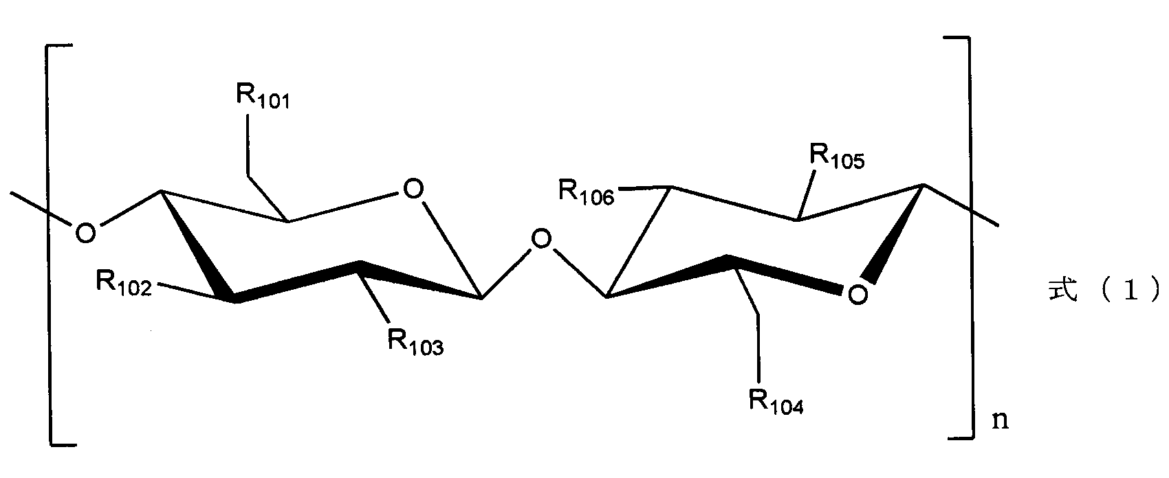
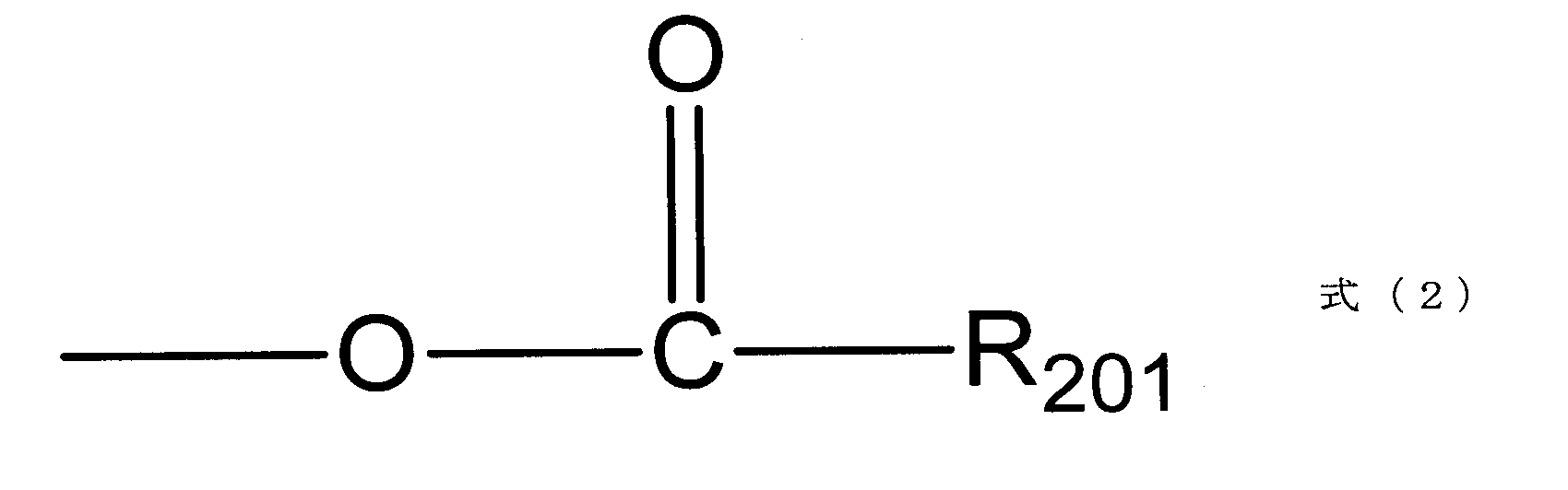

また、本実施形態の一の蓄電デバイス用セパレータは、セルロース繊維を主成分とするセパレータの繊維表面のヒドロキシ基の少なくとも一部が上記式(2)で表されるハロゲン含有エステル基に置換された蓄電デバイス用セパレータである。

また、本実施形態の一の蓄電デバイス用セパレータは、セルロース繊維を主成分とするセルロースセパレータの繊維表面のヒドロキシ基の少なくとも一部が上記式(3)で表されるハロゲン含有エーテル基に置換された蓄電デバイス用セパレータである。

別の実施形態として、表面にヒドロキシ基を有する無機材料を含む無機材料含有セパレータを、少なくともハロゲン含有カルボン酸又はハロゲン含有アルコールを含む溶液に接触させる蓄電デバイス用セパレータの製造方法について説明する。ハロゲン含有カルボン酸としてはフッ素含有カルボン酸を好ましく用いることができ、ハロゲン含有アルコールとしてはフッ素含有アルコールを好ましく用いることができる。
以下、本実施形態の二次電池について、詳細に説明する。なお、以下では蓄電デバイスの一実施形態としてリチウム二次電池を例に挙げて説明するが、本発明はこれに限定されるものではなく、例えばキャパシタ等にも適用可能である。
本実施形態のリチウム二次電池は、負極活物質を有する負極を備える。負極活物質は負極用結着材によって負極集電体上に結着されることができる。
正極は、例えば、正極活物質が正極用結着剤によって正極集電体を覆うように結着されてなる。
本実施形態で用いる電解液は、特に制限されるものではないが、例えば、支持塩と非水電解溶媒とを含む。


外装体としては、電解液に安定で、かつ十分な水蒸気バリア性を持つものであれば、適宜選択することができる。例えば、積層ラミネート型の二次電池の場合、外装体としては、アルミニウム、シリカをコーティングしたポリプロピレン、ポリエチレン等のラミネートフィルムを用いることができる。特に、体積膨張を抑制する観点から、アルミニウムラミネートフィルムを用いることが好ましい。
以下、本実施形態の蓄電デバイスの好ましい形態の一つについて、以下に説明する。
負極活物質を含む負極と、非水電解溶媒を含む電解液と、セパレータと、を少なくとも有する蓄電デバイスであって、
前記負極活物質は、リチウムと合金可能な金属(b)、およびリチウムイオンを吸蔵、放出し得る金属酸化物(c)の少なくとも1つを含み、
前記セパレータが無機繊維を主成分とする無機材料含有セパレータであることを特徴とする蓄電デバイスである。
<フッ素含有アルコールセルロースセパレータの作製方法>
セルロースセパレータ(日本高度紙工業社製、厚さ;25μm、不織布:空隙率71%、TF4425)をトリフルオロエタノールに浸し、60℃にて1時間放置した。その後、80℃に温め、トリフルオロエタノールが十分に蒸発した後、セパレータを取り出し、130℃にて一晩乾燥させた。乾燥後のセパレータ(以下、フッ素含有アルコールセルロースセパレータとも略す)について以下の通り熱安定性試験について評価を実施した。
<フッ素含有カルボン酸セルロースセパレータの作製方法>
セルロースセパレータ(日本高度紙工業社製、厚さ;25μm、不織布:空隙率71%、TF4425)を無水トリフルオロ酢酸に浸し、30℃にて2時間放置した。その後、80℃で加熱処理した。無水トリフルオロ酢酸が十分に蒸発した後、セパレータを取り出し、130℃にて一晩乾燥させた。乾燥後のセパレータ(以下、フッ素含有カルボン酸セルロースセパレータとも略す)について以下の通り熱安定性試験について評価を実施した。
<フッ素含有カルボン酸無機材料セパレータの作製方法>
無機材料含有セパレータ(サワダケミカル社製、厚さ32μm、メッシュ状)を20質量部の無水トリフルオロ酢酸に浸した後、30℃にて2時間放置した。その後、80℃で加熱処理した。無水トリフルオロ酢酸が十分に蒸発した後、セパレータを取り出し、130℃にて一晩乾燥させた。乾燥後のセパレータ(以下、フッ素含有カルボン酸無機材料セパレータとも略す)について以下の通り熱安定性試験について評価を実施した。
<フッ素含有アルコール無機材料セパレータの作製方法>
無機材料含有セパレータ(サワダケミカル社製、厚さ32μm、メッシュ状)をトリフルオロエタノールに浸し、60℃にて1時間放置した。その後、80℃に温め、トリフルオロエタノールが十分に蒸発した後、セパレータを取り出し、130℃にて一晩乾燥させた。乾燥後のセパレータ(以下、フッ素含有アルコール無機材料セパレータとも略す)について以下の通り熱安定性試験について評価を実施した。
まず、作製したフッ素含有カルボン酸セルロースセパレータとフッ素含有アルコールセルロースセパレータ、フッ素含有カルボン酸無機材料セパレータ、フッ素含有アルコール無機材料セパレータについて、熱安定性試験を以下の手法により行った。

<二次電池の性能評価>
次に、フッ素含有カルボン酸セルロースセパレータを用いて二次電池を作製した。
非水電解溶媒として、EC:DEC(30:70)に、フルオロエチレンカーボネートを5質量%混合させたものを用いた以外は、実施例1と同様にして二次電池及びセルを作製し、評価した。
非水電解溶媒として、TEP(リン酸トリエチル)にフルオロエチレンカーボネートを2質量%混合させたものを用いた以外は、実施例1と同様にして二次電池及びセルを作製し、評価した。
非水電解溶媒として、TEP(リン酸トリエチル)にフルオロエチレンカーボネートを5質量%混合させたものを用いた以外は、実施例1と同様にして二次電池及びセルを作製し、評価した。
非水電解溶媒として、TEP(リン酸トリエチル)にフルオロエチレンカーボネートを10質量%混合させたものを用いた以外は、実施例1と同様にして二次電池及びセルを作製し、評価した。
フッ素含有カルボン酸セルロースセパレータの代わりに上述のフッ素含有アルコールセルロースセパレータを用いた以外は、実施例1と同様にして二次電池及びセルを作製し、評価した。
非水電解溶媒として、EC:DEC(30:70)にフルオロエチレンカーボネートを5質量%混合させたものを用いた以外は、実施例6と同様にして二次電池及びセルを作製し、評価した。
非水電解溶媒として、TEP(リン酸トリエチル)にフルオロエチレンカーボネートを2質量%混合させたものを用いた以外は、実施例6と同様にして二次電池及びセルを作製し、評価した。
非水電解溶媒として、TEP(リン酸トリエチル)にフルオロエチレンカーボネートを5質量%混合させたものを用いた以外は、実施例6と同様にして二次電池及びセルを作製し、評価した。
非水電解溶媒として、TEP(リン酸トリエチル)にフルオロエチレンカーボネートを10質量%混合させたものを用いた以外は、実施例6と同様にして二次電池及びセルを作製し、評価した。
フッ素含有カルボン酸セルロースセパレータの代わりに上述のように処理したフッ素含有カルボン酸無機材料セパレータを用いた以外は、実施例8と同様にして二次電池及びセルを作製し、評価した。
フッ素含有カルボン酸無機材料セパレータの代わりに上述のように処理したフッ素含有アルコール無機材料セパレータを用いた以外は、実施例12と同様にして二次電池及びセルを作製し、評価した。
フッ素含有カルボン酸無機材料セパレータの代わりに、無機材料含有セパレータ(フッ素含有カルボン酸処理前のセパレータ)を用いた以外は、実施例11と同様にして二次電池及びセルを作製し、評価した。
フッ素含有カルボン酸セルロースセパレータの代わりに上述のセルロースセパレータを用いた以外は、実施例1と同様にして二次電池及びセルを作製し、評価した。

式(1)で表されるセルロース誘導体を含むことを特徴とする蓄電デバイス用セパレータ;
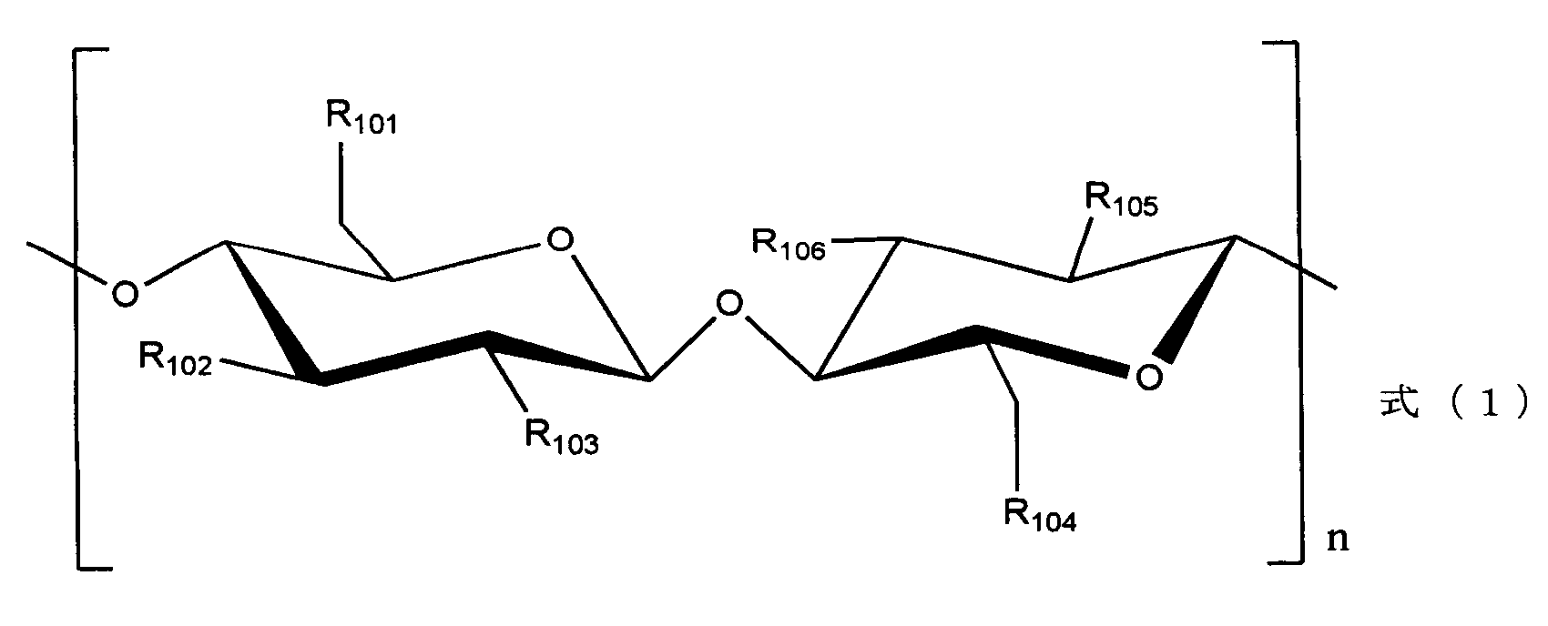

セルロース繊維を主成分とするセルロースセパレータの繊維表面のヒドロキシ基の少なくとも一部が式(4)で表されるハロゲン含有エステル基に置換された蓄電デバイス用セパレータ;

セルロース繊維を主成分とするセルロースセパレータの繊維表面のヒドロキシ基の少なくとも一部が式(5)で表されるハロゲン含有エーテル基に置換された蓄電デバイス用セパレータ;

前記セルロースセパレータが前記セルロース繊維を30質量%以上含む付記2又は3に記載の蓄電デバイス用セパレータ。
無機繊維を主成分とする無機材料含有セパレータの繊維表面にあるヒドロキシ基の少なくとも一部が式(6)で表されるハロゲン含有エステル基に置換された蓄電デバイス用セパレータ;
無機繊維を主成分とする無機材料含有セパレータの繊維表面にあるヒドロキシ基の少なくとも一部が式(7)で表されるハロゲン含有エーテル基に置換された蓄電デバイス用セパレータ;

前記無機材料含有セパレータが前記無機繊維を30質量%以上含む付記5又は6に記載の蓄電デバイス用セパレータ。
付記1乃至7のいずれかに記載の蓄電デバイス用セパレータと、負極活物質を有する負極と、支持塩及び非水電解溶媒を含む電解液と、を含む蓄電デバイス。
前記負極活物質がシリコン及び酸化シリコンから選ばれる少なくとも1種を含む付記8に記載の蓄電デバイス。
前記負極活物質が、前記シリコン、前記酸化シリコン、及び炭素材料からなる付記9に記載の蓄電デバイス。
前記非水電解溶媒がフッ素化カーボネートを含む付記8乃至10のいずれかに記載の蓄電デバイス。
前記非水電解溶媒がリン酸エステルを主溶媒として含む付記11に記載の蓄電デバイス。
セルロース繊維を主成分とするセルロースセパレータを、式(8)で表されるハロゲン含有カルボン酸を含む溶液に接触させることを特徴とする蓄電デバイス用セパレータの製造方法;

前記セルロースセパレータを前記溶液に浸した状態で加熱処理を行う付記13に記載の蓄電デバイス用セパレータの製造方法。
前記加熱処理により前記溶液の温度を50℃以上160℃以下とする付記14に記載の蓄電デバイス用セパレータの製造方法。
セルロース繊維を主成分とするセルロースセパレータを、式(9)で表されるハロゲン含有アルコールを含む溶液に接触させることを特徴とする蓄電デバイス用セパレータの製造方法;

前記セルロースセパレータを前記溶液に浸した状態で加熱処理を行う付記16に記載の蓄電デバイス用セパレータの製造方法。
前記加熱処理により前記溶液の温度を50℃以上150℃以下とする付記16又は17に記載の蓄電デバイス用セパレータの製造方法。
表面にヒドロキシ基を有する無機繊維を含む無機材料含有セパレータを、少なくとも式(10)で表されるハロゲン含有カルボン酸を含む溶液に接触させることを特徴とする蓄電デバイス用セパレータの製造方法;
前記無機材料含有セパレータを前記溶液に浸した状態で加熱処理を実施する付記19に記載の蓄電デバイス用セパレータの製造方法。
前記加熱処理により前記溶液の温度を50℃以上160℃以下とする付記20に記載の蓄電デバイス用セパレータの製造方法。
表面にヒドロキシ基を有する無機繊維を含む無機材料含有セパレータを、少なくとも式(11)で表されるハロゲン含有アルコールを含む溶液に接触させることを特徴とする蓄電デバイス用セパレータの製造方法;

前記無機材料含有セパレータを前記溶液に浸した状態で加熱処理を実施する付記22に記載の蓄電デバイス用セパレータの製造方法。
前記加熱処理により前記溶液の温度を50℃以上150℃以下とする付記22又は23記載の蓄電デバイス用セパレータの製造方法。
前記無機繊維は、アルミナ繊維、炭素繊維、又はガラス繊維である付記19乃至24のいずれかに記載の蓄電デバイス用セパレータの製造方法。
前記無機材料含有セパレータは、アルミナ粒子又はシリカ粒子を含む付記25に記載の蓄電デバイス用セパレータの製造方法。
付記13乃至26のいずれかに記載の製造方法により製造された蓄電デバイス用セパレータと、負極活物質を有する負極と、支持塩及び非水電解溶媒を含む電解液と、を含む蓄電デバイス。
前記負極活物質がシリコン及び酸化シリコンから選ばれる少なくとも1種を含む付記27に記載の蓄電デバイス。
前記負極活物質が、前記シリコン、前記酸化シリコン、及び炭素材料からなる付記28に記載の蓄電デバイス。
前記非水電解溶媒がフッ素化カーボネートを含む付記28又は29に記載の蓄電デバイス。
前記非水電解溶媒がリン酸エステル化合物を主溶媒として含む付記30に記載の蓄電デバイス。
b セパレータ
c 正極
d 負極集電体
e 正極集電体
f 正極端子
g 負極端子
Claims (25)
- 無機繊維を主成分とする無機材料含有セパレータの繊維表面にあるヒドロキシ基の少なくとも一部が式(6)で表されるハロゲン含有エステル基に置換された蓄電デバイス用セパレータ;

[式(6)中、R201は、ハロゲン原子を含有するアルキル基を表す。]。 - 無機繊維を主成分とする無機材料含有セパレータの繊維表面にあるヒドロキシ基の少なくとも一部が式(7)で表されるハロゲン含有エーテル基に置換された蓄電デバイス用セパレータ;

[式(7)中、R301は、ハロゲン原子を含有するアルキル基を表す。]。 - 前記無機繊維は、アルミナ繊維、炭素繊維、又はガラス繊維である請求項1又は2に記載の蓄電デバイス用セパレータ。
- 前記無機材料含有セパレータが前記無機繊維を30質量%以上含む請求項1乃至3のいずれかに記載の蓄電デバイス用セパレータ。
- 式(1)で表されるセルロース誘導体を含むことを特徴とする蓄電デバイス用セパレータ;

[式(1)中、R101~R106は、それぞれ独立に、ヒドロキシ基、ハロゲン含有エステル基、又はハロゲン含有エーテル基を表し、R101~R106のうち少なくとも一つがハロゲン含有エステル基又はハロゲン含有エーテル基である。ハロゲン含有エステル基は式(2)で表され、ハロゲン含有エーテル基は式(3)で表される。nは2以上の整数であり、R101~R106のそれぞれはnごとにそれぞれ独立している。]
[式(2)中、R201は、ハロゲン原子を含有するアルキル基を表す。]

[式(3)中、R301は、ハロゲン原子を含有するアルキル基を表す。]。 - セルロース繊維を主成分とするセルロースセパレータの繊維表面のヒドロキシ基の少なくとも一部が式(5)で表されるハロゲン含有エーテル基に置換された蓄電デバイス用セパレータ;

[式(5)中、R301は、ハロゲン原子を含有するアルキル基を表す。]。 - セルロース繊維を主成分とするセルロースセパレータの繊維表面のヒドロキシ基の少なくとも一部が式(4)で表されるハロゲン含有エステル基に置換された蓄電デバイス用セパレータ;
[式(4)中、R201は、ハロゲン原子を含有するアルキル基を表す。]。 - 前記セルロースセパレータが前記セルロース繊維を30質量%以上含む請求項6又は7に記載の蓄電デバイス用セパレータ。
- 請求項1乃至8のいずれかに記載の蓄電デバイス用セパレータと、負極活物質を有する負極と、支持塩及び非水電解溶媒を含む電解液と、を含む蓄電デバイス。
- 前記負極活物質がシリコン及び酸化シリコンから選ばれる少なくとも1種を含む請求項9に記載の蓄電デバイス。
- 前記非水電解溶媒がフッ素化カーボネートを含む請求項9又は10に記載の蓄電デバイス。
- 前記非水電解溶媒がリン酸エステルを主溶媒として含む請求項11に記載の蓄電デバイス。
- 表面にヒドロキシ基を有する無機繊維を含む無機材料含有セパレータを、少なくとも式(11)で表されるハロゲン含有アルコールを含む溶液に接触させることを特徴とする蓄電デバイス用セパレータの製造方法;

[式(11)中、R501は、ハロゲン原子を含有するアルキル基を表す。]。 - 前記無機材料含有セパレータを前記溶液に浸した状態で加熱処理を実施する請求項13に記載の蓄電デバイス用セパレータの製造方法。
- 表面にヒドロキシ基を有する無機繊維を含む無機材料含有セパレータを、少なくとも式(10)で表されるハロゲン含有カルボン酸を含む溶液に接触させることを特徴とする蓄電デバイス用セパレータの製造方法;

[式(10)中、R401は、ハロゲン原子を含有するアルキル基を表す。]。 - 前記無機材料含有セパレータを前記溶液に浸した状態で加熱処理を実施する請求項15に記載の蓄電デバイス用セパレータの製造方法。
- 前記無機繊維は、アルミナ繊維、炭素繊維、又はガラス繊維である請求項13乃至16のいずれかに記載の蓄電デバイス用セパレータの製造方法。
- セルロース繊維を主成分とするセルロースセパレータを、式(9)で表されるハロゲン含有アルコールを含む溶液に接触させることを特徴とする蓄電デバイス用セパレータの製造方法;

[式(9)中、R501は、ハロゲン原子を含有するアルキル基を表す。]。 - 前記セルロースセパレータを前記溶液に浸した状態で加熱処理を行う請求項18に記載の蓄電デバイス用セパレータの製造方法。
- セルロース繊維を主成分とするセルロースセパレータを、式(8)で表されるハロゲン含有カルボン酸を含む溶液に接触させることを特徴とする蓄電デバイス用セパレータの製造方法;

[式(8)中、R401は、ハロゲン原子を含有するアルキル基を表す。]。 - 前記セルロースセパレータを前記溶液に浸した状態で加熱処理を行う請求項20に記載の蓄電デバイス用セパレータの製造方法。
- 負極活物質を含む負極と、非水電解溶媒を含む電解液と、セパレータと、を少なくとも含有する蓄電デバイスであって、
前記負極活物質は、リチウムと合金可能な金属(b)、およびリチウムイオンを吸蔵、放出し得る金属酸化物(c)の少なくとも1つを含み、
前記セパレータが無機繊維を主成分とする無機材料含有セパレータであることを特徴とする蓄電デバイス。 - 前記非水電解溶媒が、リン酸エステル化合物を主溶媒とする請求項22に記載の蓄電デバイス。
- 前記リン酸エステル化合物が下記式(10)で表される請求項22又は23に記載の蓄電デバイス。
- 前記金属(b)がシリコン、前記金属酸化物(c)が酸化シリコンである請求項22乃至24のいずれかに記載の蓄電デバイス。
Priority Applications (4)
| Application Number | Priority Date | Filing Date | Title |
|---|---|---|---|
| CN201280010369.XA CN103392247B (zh) | 2011-02-24 | 2012-02-21 | 蓄电装置用隔膜和蓄电装置 |
| JP2013501047A JP5962647B2 (ja) | 2011-02-24 | 2012-02-21 | 非水電解液二次電池用セパレータ及び非水電解液二次電池 |
| US13/981,027 US9142357B2 (en) | 2011-02-24 | 2012-02-21 | Separator for electric storage device and electric storage device |
| EP12749048.0A EP2680341B1 (en) | 2011-02-24 | 2012-02-21 | Separator for accumulators, and accumulator |
Applications Claiming Priority (4)
| Application Number | Priority Date | Filing Date | Title |
|---|---|---|---|
| JP2011038318 | 2011-02-24 | ||
| JP2011-038318 | 2011-02-24 | ||
| JP2011159107 | 2011-07-20 | ||
| JP2011-159107 | 2011-07-20 |
Publications (1)
| Publication Number | Publication Date |
|---|---|
| WO2012115093A1 true WO2012115093A1 (ja) | 2012-08-30 |
Family
ID=46720870
Family Applications (1)
| Application Number | Title | Priority Date | Filing Date |
|---|---|---|---|
| PCT/JP2012/054103 WO2012115093A1 (ja) | 2011-02-24 | 2012-02-21 | 蓄電デバイス用セパレータ及び蓄電デバイス |
Country Status (5)
| Country | Link |
|---|---|
| US (1) | US9142357B2 (ja) |
| EP (1) | EP2680341B1 (ja) |
| JP (1) | JP5962647B2 (ja) |
| CN (1) | CN103392247B (ja) |
| WO (1) | WO2012115093A1 (ja) |
Cited By (5)
| Publication number | Priority date | Publication date | Assignee | Title |
|---|---|---|---|---|
| JP2014103038A (ja) * | 2012-11-21 | 2014-06-05 | Nec Corp | 電池用セパレータ、その製造方法、およびリチウムイオン二次電池 |
| CN103956450A (zh) * | 2014-05-16 | 2014-07-30 | 中国东方电气集团有限公司 | 一种锂离子电池用复合隔膜及其制备方法 |
| CN104919554A (zh) * | 2012-12-20 | 2015-09-16 | 日本高度纸工业株式会社 | 铝电解电容器用隔膜及铝电解电容器 |
| WO2016152876A1 (ja) * | 2015-03-24 | 2016-09-29 | 日本電気株式会社 | リチウムイオン二次電池、およびその製造方法 |
| US10103384B2 (en) | 2013-07-09 | 2018-10-16 | Evonik Degussa Gmbh | Electroactive polymers, manufacturing process thereof, electrode and use thereof |
Families Citing this family (10)
| Publication number | Priority date | Publication date | Assignee | Title |
|---|---|---|---|---|
| US10102982B2 (en) | 2015-03-03 | 2018-10-16 | Ut-Battelle Llc | Electrolytes for supercapacitors |
| EP3353844B1 (en) | 2015-03-27 | 2022-05-11 | Mason K. Harrup | All-inorganic solvents for electrolytes |
| MY195773A (en) | 2016-05-20 | 2023-02-11 | Kyocera Avx Components Corp | Multi-Cell Ultracapacitor |
| KR102635455B1 (ko) | 2016-05-20 | 2024-02-13 | 교세라 에이브이엑스 컴포넌츠 코포레이션 | 고온용 울트라커패시터 |
| US10707531B1 (en) | 2016-09-27 | 2020-07-07 | New Dominion Enterprises Inc. | All-inorganic solvents for electrolytes |
| US11830672B2 (en) | 2016-11-23 | 2023-11-28 | KYOCERA AVX Components Corporation | Ultracapacitor for use in a solder reflow process |
| FR3070532A1 (fr) * | 2017-08-22 | 2019-03-01 | Commissariat A L'energie Atomique Et Aux Energies Alternatives | Composition electrolytique comprenant un additif de la famille des phosphazenes utilisables pour des supercondensateurs |
| CN107959053B (zh) * | 2017-11-28 | 2020-08-04 | 南开大学 | 改善高镍正极材料循环稳定性的功能性电解液及制备方法 |
| KR102353062B1 (ko) | 2018-09-03 | 2022-01-19 | 주식회사 엘지에너지솔루션 | 분리막 기재가 없는 이차전지용 분리막 |
| CA3033917A1 (fr) * | 2019-02-15 | 2020-08-15 | Nicolas DELAPORTE | Separateurs a base de cellulose avec retardateur de flamme, et leurs utilisations en electrochimie |
Citations (13)
| Publication number | Priority date | Publication date | Assignee | Title |
|---|---|---|---|---|
| JPS61284070A (ja) * | 1985-06-11 | 1986-12-15 | Showa Denko Kk | 非水系二次電池 |
| JPH08306352A (ja) | 1995-05-10 | 1996-11-22 | Nippon Koudoshi Kogyo Kk | 非水系電池 |
| WO1998032184A1 (en) * | 1997-01-16 | 1998-07-23 | Mitsubishi Paper Mills Limited | Separator for nonaqueous electrolyte batteries, nonaqueous electrolyte battery using it, and method for manufacturing separator for nonaqueous electrolyte batteries |
| JP2000048792A (ja) * | 1998-07-29 | 2000-02-18 | Mitsubishi Paper Mills Ltd | 非水電解液電池およびその製造方法 |
| JP2000173574A (ja) * | 1998-12-04 | 2000-06-23 | Mitsubishi Paper Mills Ltd | 非水電解液電池の製造方法 |
| JP2001148242A (ja) * | 1998-12-24 | 2001-05-29 | Seiko Instruments Inc | 非水電解質二次電池 |
| JP2003123724A (ja) | 2001-10-11 | 2003-04-25 | Toyota Central Res & Dev Lab Inc | リチウム二次電池用セパレータおよびそれを用いたリチウム二次電池 |
| JP2004047404A (ja) | 2002-05-17 | 2004-02-12 | Shin Etsu Chem Co Ltd | 導電性珪素複合体及びその製造方法並びに非水電解質二次電池用負極材 |
| JP2004327279A (ja) * | 2003-04-25 | 2004-11-18 | Sii Micro Parts Ltd | 非水電解質二次電池 |
| JP2004342318A (ja) * | 2002-03-22 | 2004-12-02 | Nisshinbo Ind Inc | 非水電解質二次電池の充電方法 |
| JP2005078847A (ja) * | 2003-08-28 | 2005-03-24 | Mitsubishi Chemicals Corp | 二次電池用非水電解液及びそれを用いた非水系二次電池 |
| JP2006221972A (ja) * | 2005-02-10 | 2006-08-24 | Sony Corp | 電解液および電池 |
| JP2008243482A (ja) * | 2007-03-26 | 2008-10-09 | Sony Corp | 非水電解質電池 |
Family Cites Families (17)
| Publication number | Priority date | Publication date | Assignee | Title |
|---|---|---|---|---|
| JPH07335192A (ja) * | 1994-06-02 | 1995-12-22 | Nippon Muki Co Ltd | リチウム電池用セパレータ |
| JP3741410B2 (ja) * | 1998-07-31 | 2006-02-01 | 日本バイリーン株式会社 | アルカリ電池用セパレータ及びその製造方法 |
| US6489062B1 (en) | 1998-12-24 | 2002-12-03 | Seiko Instruments Inc. | Non-aqueous electrolyte secondary battery having heat-resistant electrodes |
| JP2001214366A (ja) * | 1999-07-15 | 2001-08-07 | Sekisui Chem Co Ltd | 不織布及びその製造方法、及び前記不織布を用いた2次電池用セパレータ及びその製造方法 |
| JP3585833B2 (ja) | 2000-12-26 | 2004-11-04 | 東洋炭素株式会社 | 合成若しくは天然高分子材料の表面改質方法 |
| JP2002249589A (ja) * | 2001-02-23 | 2002-09-06 | Nippon Mektron Ltd | ゲル組成物 |
| TW579613B (en) | 2001-09-27 | 2004-03-11 | Nisshin Spinning | Nonaqueous electrolyte secondary cell, power supply comprising the secondary cell, portable device, transportable or movable machine, electric apparatus for home use, and method for charging nonaqueous electrolyte secondary cell |
| JP2004146346A (ja) * | 2002-08-28 | 2004-05-20 | Nisshinbo Ind Inc | 非水電解質および非水電解質二次電池 |
| JP4403447B2 (ja) * | 2003-03-27 | 2010-01-27 | 大阪瓦斯株式会社 | 非水系二次電池 |
| JP4803984B2 (ja) * | 2004-09-22 | 2011-10-26 | 帝人株式会社 | リチウムイオン二次電池用セパレータおよびその製造方法とリチウムイオン二次電池 |
| JP5023261B2 (ja) | 2005-09-08 | 2012-09-12 | フジコピアン株式会社 | リチウム二次電池用セパレータおよびそれを用いたリチウム二次電池 |
| US20070202394A1 (en) * | 2006-02-28 | 2007-08-30 | Viavattine Joseph J | Separator systems for batteries |
| JP5260889B2 (ja) * | 2006-05-19 | 2013-08-14 | パナソニック株式会社 | 非水電解質二次電池 |
| KR100820162B1 (ko) * | 2006-08-07 | 2008-04-10 | 한국과학기술연구원 | 내열성 초극세 섬유상 분리막 및 그 제조 방법과, 이를 이용한 이차전지 |
| JP2010278015A (ja) * | 2006-09-22 | 2010-12-09 | Mitsubishi Chemicals Corp | リチウム二次電池正極材料用リチウムニッケルマンガンコバルト系複合酸化物粉体、その製造方法、及び噴霧乾燥粉体、並びにそれを用いたリチウム二次電池用正極及びリチウム二次電池 |
| JP5589264B2 (ja) * | 2008-06-06 | 2014-09-17 | 三菱化学株式会社 | 非水系電解液及び非水系電解液電池 |
| CN102077406B (zh) * | 2008-06-30 | 2015-03-04 | 大金工业株式会社 | 锂二次电池 |
-
2012
- 2012-02-21 JP JP2013501047A patent/JP5962647B2/ja active Active
- 2012-02-21 EP EP12749048.0A patent/EP2680341B1/en active Active
- 2012-02-21 WO PCT/JP2012/054103 patent/WO2012115093A1/ja active Application Filing
- 2012-02-21 CN CN201280010369.XA patent/CN103392247B/zh active Active
- 2012-02-21 US US13/981,027 patent/US9142357B2/en active Active
Patent Citations (13)
| Publication number | Priority date | Publication date | Assignee | Title |
|---|---|---|---|---|
| JPS61284070A (ja) * | 1985-06-11 | 1986-12-15 | Showa Denko Kk | 非水系二次電池 |
| JPH08306352A (ja) | 1995-05-10 | 1996-11-22 | Nippon Koudoshi Kogyo Kk | 非水系電池 |
| WO1998032184A1 (en) * | 1997-01-16 | 1998-07-23 | Mitsubishi Paper Mills Limited | Separator for nonaqueous electrolyte batteries, nonaqueous electrolyte battery using it, and method for manufacturing separator for nonaqueous electrolyte batteries |
| JP2000048792A (ja) * | 1998-07-29 | 2000-02-18 | Mitsubishi Paper Mills Ltd | 非水電解液電池およびその製造方法 |
| JP2000173574A (ja) * | 1998-12-04 | 2000-06-23 | Mitsubishi Paper Mills Ltd | 非水電解液電池の製造方法 |
| JP2001148242A (ja) * | 1998-12-24 | 2001-05-29 | Seiko Instruments Inc | 非水電解質二次電池 |
| JP2003123724A (ja) | 2001-10-11 | 2003-04-25 | Toyota Central Res & Dev Lab Inc | リチウム二次電池用セパレータおよびそれを用いたリチウム二次電池 |
| JP2004342318A (ja) * | 2002-03-22 | 2004-12-02 | Nisshinbo Ind Inc | 非水電解質二次電池の充電方法 |
| JP2004047404A (ja) | 2002-05-17 | 2004-02-12 | Shin Etsu Chem Co Ltd | 導電性珪素複合体及びその製造方法並びに非水電解質二次電池用負極材 |
| JP2004327279A (ja) * | 2003-04-25 | 2004-11-18 | Sii Micro Parts Ltd | 非水電解質二次電池 |
| JP2005078847A (ja) * | 2003-08-28 | 2005-03-24 | Mitsubishi Chemicals Corp | 二次電池用非水電解液及びそれを用いた非水系二次電池 |
| JP2006221972A (ja) * | 2005-02-10 | 2006-08-24 | Sony Corp | 電解液および電池 |
| JP2008243482A (ja) * | 2007-03-26 | 2008-10-09 | Sony Corp | 非水電解質電池 |
Non-Patent Citations (2)
| Title |
|---|
| JOURNAL OF THE ELECTROCHEMICAL SOCIETY, vol. 148, no. 10, 2001, pages A1058 - A1065 |
| See also references of EP2680341A4 |
Cited By (5)
| Publication number | Priority date | Publication date | Assignee | Title |
|---|---|---|---|---|
| JP2014103038A (ja) * | 2012-11-21 | 2014-06-05 | Nec Corp | 電池用セパレータ、その製造方法、およびリチウムイオン二次電池 |
| CN104919554A (zh) * | 2012-12-20 | 2015-09-16 | 日本高度纸工业株式会社 | 铝电解电容器用隔膜及铝电解电容器 |
| US10103384B2 (en) | 2013-07-09 | 2018-10-16 | Evonik Degussa Gmbh | Electroactive polymers, manufacturing process thereof, electrode and use thereof |
| CN103956450A (zh) * | 2014-05-16 | 2014-07-30 | 中国东方电气集团有限公司 | 一种锂离子电池用复合隔膜及其制备方法 |
| WO2016152876A1 (ja) * | 2015-03-24 | 2016-09-29 | 日本電気株式会社 | リチウムイオン二次電池、およびその製造方法 |
Also Published As
| Publication number | Publication date |
|---|---|
| US9142357B2 (en) | 2015-09-22 |
| US20130302702A1 (en) | 2013-11-14 |
| EP2680341A4 (en) | 2018-03-28 |
| EP2680341A1 (en) | 2014-01-01 |
| EP2680341B1 (en) | 2019-06-12 |
| JPWO2012115093A1 (ja) | 2014-07-07 |
| CN103392247B (zh) | 2016-08-10 |
| CN103392247A (zh) | 2013-11-13 |
| JP5962647B2 (ja) | 2016-08-03 |
Similar Documents
| Publication | Publication Date | Title |
|---|---|---|
| JP5962647B2 (ja) | 非水電解液二次電池用セパレータ及び非水電解液二次電池 | |
| JP5962646B2 (ja) | 非水電解液二次電池用セパレータ及び非水電解液二次電池 | |
| JP6221669B2 (ja) | 二次電池 | |
| KR101532847B1 (ko) | 이차 전지 및 그것에 사용되는 이차 전지용 전해액 | |
| US11005095B2 (en) | Negative electrode active material, mixed negative electrode active material, and method for producing negative electrode active material | |
| JP6269475B2 (ja) | 二次電池 | |
| KR101440347B1 (ko) | 다층 구조의 이차전지용 음극 및 이를 포함하는 리튬 이차전지 | |
| WO2014091856A1 (ja) | セパレータ、電極素子、蓄電デバイスおよび前記セパレータの製造方法 | |
| US20190123344A1 (en) | Negative electrode active material, mixed negative electrode active material, and method for producing negative electrode active material | |
| WO2013176275A1 (ja) | 蓄電デバイス | |
| WO2013176273A1 (ja) | 蓄電デバイス | |
| JP6064540B2 (ja) | 電池用セパレータ、その製造方法、およびリチウムイオン二次電池 | |
| WO2017098850A1 (ja) | 二次電池用電解質層、二次電池、電池パック、電動車両、電力貯蔵システム、電動工具および電子機器 | |
| KR20210011342A (ko) | 리튬 이차전지 | |
| CN108292781B (zh) | 二次电池、电池组、电动车辆、电力储存系统、电动工具以及电子设备 | |
| US20120276448A1 (en) | Negative electrode material for an electrical storage device, and negative electrode for an electrical storage device using the same | |
| KR101588250B1 (ko) | 이차전지용 양극 활물질의 제조 방법 및 이를 사용해서 제조되는 양극 활물질 | |
| KR20190105885A (ko) | 비수 전해액 및 이를 포함하는 리튬 이차 전지 | |
| JP6388009B2 (ja) | 電池用セパレータ、その製造方法、およびリチウムイオン二次電池 | |
| JP2014116271A (ja) | セパレータ、電極素子、蓄電デバイスおよび前記セパレータの製造方法 | |
| KR20220090470A (ko) | 다공성 무기물 입자 및 이를 포함하는 전지 | |
| KR20140008013A (ko) | 전극조립체 및 이를 포함하는 리튬 이차전지 | |
| KR20140003095A (ko) | 전극조립체 및 이를 포함하는 리튬 이차전지 |
Legal Events
| Date | Code | Title | Description |
|---|---|---|---|
| 121 | Ep: the epo has been informed by wipo that ep was designated in this application |
Ref document number: 12749048 Country of ref document: EP Kind code of ref document: A1 |
|
| WWE | Wipo information: entry into national phase |
Ref document number: 13981027 Country of ref document: US |
|
| ENP | Entry into the national phase |
Ref document number: 2013501047 Country of ref document: JP Kind code of ref document: A |
|
| NENP | Non-entry into the national phase |
Ref country code: DE |
|
| WWE | Wipo information: entry into national phase |
Ref document number: 2012749048 Country of ref document: EP |