WO2012108282A1 - 自動車のフロントサイドフレーム構造 - Google Patents
自動車のフロントサイドフレーム構造 Download PDFInfo
- Publication number
- WO2012108282A1 WO2012108282A1 PCT/JP2012/051805 JP2012051805W WO2012108282A1 WO 2012108282 A1 WO2012108282 A1 WO 2012108282A1 JP 2012051805 W JP2012051805 W JP 2012051805W WO 2012108282 A1 WO2012108282 A1 WO 2012108282A1
- Authority
- WO
- WIPO (PCT)
- Prior art keywords
- front side
- side frame
- bent
- bent portion
- frame structure
- Prior art date
Links
Images


Classifications
-
- B—PERFORMING OPERATIONS; TRANSPORTING
- B62—LAND VEHICLES FOR TRAVELLING OTHERWISE THAN ON RAILS
- B62D—MOTOR VEHICLES; TRAILERS
- B62D21/00—Understructures, i.e. chassis frame on which a vehicle body may be mounted
- B62D21/15—Understructures, i.e. chassis frame on which a vehicle body may be mounted having impact absorbing means, e.g. a frame designed to permanently or temporarily change shape or dimension upon impact with another body
- B62D21/152—Front or rear frames
-
- B—PERFORMING OPERATIONS; TRANSPORTING
- B62—LAND VEHICLES FOR TRAVELLING OTHERWISE THAN ON RAILS
- B62D—MOTOR VEHICLES; TRAILERS
- B62D25/00—Superstructure or monocoque structure sub-units; Parts or details thereof not otherwise provided for
- B62D25/20—Floors or bottom sub-units
-
- B—PERFORMING OPERATIONS; TRANSPORTING
- B62—LAND VEHICLES FOR TRAVELLING OTHERWISE THAN ON RAILS
- B62D—MOTOR VEHICLES; TRAILERS
- B62D29/00—Superstructures, understructures, or sub-units thereof, characterised by the material thereof
- B62D29/007—Superstructures, understructures, or sub-units thereof, characterised by the material thereof predominantly of special steel or specially treated steel, e.g. stainless steel or locally surface hardened steel
-
- C—CHEMISTRY; METALLURGY
- C21—METALLURGY OF IRON
- C21D—MODIFYING THE PHYSICAL STRUCTURE OF FERROUS METALS; GENERAL DEVICES FOR HEAT TREATMENT OF FERROUS OR NON-FERROUS METALS OR ALLOYS; MAKING METAL MALLEABLE, e.g. BY DECARBURISATION OR TEMPERING
- C21D1/00—General methods or devices for heat treatment, e.g. annealing, hardening, quenching or tempering
- C21D1/06—Surface hardening
- C21D1/09—Surface hardening by direct application of electrical or wave energy; by particle radiation
- C21D1/10—Surface hardening by direct application of electrical or wave energy; by particle radiation by electric induction
-
- C—CHEMISTRY; METALLURGY
- C21—METALLURGY OF IRON
- C21D—MODIFYING THE PHYSICAL STRUCTURE OF FERROUS METALS; GENERAL DEVICES FOR HEAT TREATMENT OF FERROUS OR NON-FERROUS METALS OR ALLOYS; MAKING METAL MALLEABLE, e.g. BY DECARBURISATION OR TEMPERING
- C21D9/00—Heat treatment, e.g. annealing, hardening, quenching or tempering, adapted for particular articles; Furnaces therefor
- C21D9/08—Heat treatment, e.g. annealing, hardening, quenching or tempering, adapted for particular articles; Furnaces therefor for tubular bodies or pipes
- C21D9/085—Cooling or quenching
-
- F—MECHANICAL ENGINEERING; LIGHTING; HEATING; WEAPONS; BLASTING
- F16—ENGINEERING ELEMENTS AND UNITS; GENERAL MEASURES FOR PRODUCING AND MAINTAINING EFFECTIVE FUNCTIONING OF MACHINES OR INSTALLATIONS; THERMAL INSULATION IN GENERAL
- F16F—SPRINGS; SHOCK-ABSORBERS; MEANS FOR DAMPING VIBRATION
- F16F7/00—Vibration-dampers; Shock-absorbers
- F16F7/12—Vibration-dampers; Shock-absorbers using plastic deformation of members
- F16F7/123—Deformation involving a bending action, e.g. strap moving through multiple rollers, folding of members
-
- C—CHEMISTRY; METALLURGY
- C21—METALLURGY OF IRON
- C21D—MODIFYING THE PHYSICAL STRUCTURE OF FERROUS METALS; GENERAL DEVICES FOR HEAT TREATMENT OF FERROUS OR NON-FERROUS METALS OR ALLOYS; MAKING METAL MALLEABLE, e.g. BY DECARBURISATION OR TEMPERING
- C21D9/00—Heat treatment, e.g. annealing, hardening, quenching or tempering, adapted for particular articles; Furnaces therefor
- C21D9/0068—Heat treatment, e.g. annealing, hardening, quenching or tempering, adapted for particular articles; Furnaces therefor for particular articles not mentioned below
-
- Y—GENERAL TAGGING OF NEW TECHNOLOGICAL DEVELOPMENTS; GENERAL TAGGING OF CROSS-SECTIONAL TECHNOLOGIES SPANNING OVER SEVERAL SECTIONS OF THE IPC; TECHNICAL SUBJECTS COVERED BY FORMER USPC CROSS-REFERENCE ART COLLECTIONS [XRACs] AND DIGESTS
- Y02—TECHNOLOGIES OR APPLICATIONS FOR MITIGATION OR ADAPTATION AGAINST CLIMATE CHANGE
- Y02P—CLIMATE CHANGE MITIGATION TECHNOLOGIES IN THE PRODUCTION OR PROCESSING OF GOODS
- Y02P10/00—Technologies related to metal processing
- Y02P10/25—Process efficiency
Definitions
- a front side frame disposed in a front-rear direction at a front portion of a vehicle body is formed of a tubular hollow member having a constant cross section, and the front side frame is a first bent portion on the front side behind a power unit mounting portion to which a power unit is mounted. And a second side bent portion of the vehicle.
- a steel pipe delivery device that delivers a steel pipe in its longitudinal direction, a bending fulcrum member that guides and supports the delivered steel pipe, a high-frequency heating coil that continuously heats the steel pipe, and a bending moment at the part heated by gripping the steel pipe
- Patent Document 1 A steel pipe hot working apparatus provided with a bending apparatus for bending by applying a bending process and a cooling apparatus for quenching and quenching the bent steel pipe is known from Patent Document 1 below. According to this invention, since it is possible to perform the bending process and the quenching process of the steel pipe at the same time, a high-strength front side frame bent into a predetermined shape can be obtained.
- the front side frame of the automobile has a front half portion supporting a power unit composed of an engine and a transmission formed in a substantially linear shape, and a rear half portion connected to the rear of the front half portion is arranged downward and in order to avoid interference with the left and right front wheels. It is formed in a shape bent in an S shape on the inner side in the vehicle width direction.
- the bent part of the latter half can be bent to secure the shock absorbing stroke, but the substantially straight front half can be bent accurately. It was difficult to do so, and there was still room to increase the shock absorption stroke.
- the present invention has been made in view of the above-mentioned circumstances, and an object thereof is to further increase the shock absorption stroke by accurately bending the front side frame at the time of a frontal collision of an automobile.
- the front side frame disposed in the front-rear direction at the front portion of the vehicle body is formed of a tubular hollow member having a constant cross section, and the front side frame is attached to the power unit to which the power unit is attached.
- the front side frame bends outwardly in the vehicle width direction in front of the power unit mounting portion.
- a first fragile portion is provided in the vicinity of the second bent portion, the first fragile portion being weaker than other portions of the front side frame, and the front side frame in the vicinity of the third bent portion.
- a front side frame structure for an automobile characterized in that a second fragile portion that is weaker than other portions is formed. It proposed.
- a front side frame structure of an automobile characterized in that the strength of the front side frame is enhanced by a quenching process.
- the front side frame in addition to the first or second configuration, further includes another bent portion in front of or behind the third bent portion.
- a side frame structure is proposed.
- the second fragile portion in the vicinity of the third bent portion is offset forward or backward from the position of the third bent portion.
- a front side frame structure for an automobile having the fourth feature is proposed.
- the front side frame sends a steel pipe along a longitudinal direction from a steel pipe sending device, and sends it from the steel pipe sending device.
- the steel pipe is heated by a high frequency heating coil, the steel pipe heated by the high frequency heating coil is bent by a bending device, and the steel pipe bent by the bending device is cooled by a cooling device and quenched.
- a front side frame structure for an automobile which is characterized in that it is manufactured in the fifth aspect, is proposed.
- the second fragile portion is on the third bent portion, and the second fragile portion is a part of the hardened front side frame.
- a front side frame structure of an automobile is proposed, which is characterized by being formed by annealing treatment.
- the power unit mounting portion is configured by vertically stacking two tubular hollow members, and the kick-up portion is formed by combining at least two sheet metal members.
- a front side frame structure for an automobile is proposed, which has a seventh feature of being configured in a closed cross section.
- an automobile front side frame structure is proposed, wherein the tubular hollow member has a polygonal cross section.
- a front side frame structure for an automobile characterized in that the ridge line of the sheet metal member is connected to the ridge line of the tubular hollow member is proposed. Is done.
- the kick-up portion has a first bent portion on the front side and a second bent portion on the rear side, and is S-shaped.
- a vehicle front side frame structure characterized in that the aspect ratio of the intermediate portion bent between the first and second bent portions is less than 1 is proposed.
- a front side frame structure for an automobile according to an eleventh feature in which the aspect ratio increases from the intermediate portion toward the second bent portion. Is done.
- the fourth bent portion 43 of the embodiment corresponds to another bent portion of the present invention, and the first and second tubular hollow members 117 and 118 correspond to the tubular hollow member of the present invention.
- the first to third sheet metal members 119 to 121 of the form correspond to the sheet metal members of the present invention.
- the second bent portion on the rear side of the first and second bent portions on the rear side of the power unit mounting portion of the front side frame formed of a tubular hollow member having a constant cross section. Since the first fragile portion is provided in the vicinity and the second fragile portion is provided in the vicinity of the third bent portion that is convexly bent outward in the vehicle width direction in the power unit mounting portion, it is constituted by a tubular hollow member at the time of a frontal collision of the automobile
- the high strength CFC front side frame can be bent not only at the first fragile portion but also at the second fragile portion, and the impact absorption stroke can be increased to enhance the impact energy absorption effect.
- the strength of the front side frame is increased by the quenching process, so that it is possible to increase the strength of the front side frame without providing a special reinforcing part, thereby reducing the weight. can do.
- the front side frame further includes another bent portion in front of or behind the third bent portion, so that the degree of freedom in designing the shape of the front side frame is increased. Since the front side frame bends at the fragile portion near the third bent portion at the time of a frontal collision of the automobile, the bending moment acting on the other bent portions becomes small and the bent portion does not bend.
- the second fragile portion in the vicinity of the third bent portion is offset forward or backward from the position of the third bent portion, the second fragile portion can be bent. Since it can do, the position of a 2nd weak part can be changed and the design freedom of a front side frame can be raised.
- the steel pipe delivered from the steel pipe delivery device is heated by the high-frequency heating coil and bent by the bending device, and then cooled by the cooling device and subjected to the quenching process, thereby the front side frame. Therefore, it is possible to easily manufacture a high-strength front side frame by simultaneously performing a bending process and a quenching process.
- the second fragile portion is on the third bent portion, the second fragile portion is annealed on a part of the front side frame that has been quenched. Can be formed. Moreover, the second weakened part is removed from the internal stress by the annealing process, resulting in a uniform softened internal structure, and the collision energy is absorbed by the entire cross section of the second weakened part when the collision load is input while ensuring the vehicle body rigidity under normal conditions. can do.
- the power unit mounting portion on which a large axial force acts at the time of a frontal collision of an automobile is configured by stacking two tubular hollow members on top and bottom, so that it can withstand the axial force.
- Strength can be easily secured, and the kick-up part in which bending moments of different magnitudes are applied depending on the part is constructed in a closed cross section by combining at least two sheet metal members. It is easy to set and adjust the strength. As a result, it is possible to minimize the excess strength while ensuring the necessary strength, and achieve both the strength and weight reduction of the front side frame.
- the tubular hollow member has a polygonal cross section, the strength can be increased by increasing the number of ridge lines.
- the ninth configuration of the present invention since the ridge line of the sheet metal member is connected to the ridge line of the tubular hollow member, the load is transmitted from the ridge line of the tubular hollow member to the ridge line of the sheet metal member, so that the power unit mounting portion and the kick-up portion The strength of the joint portion can be increased.
- the kick-up portion has the first bent portion on the front side and the second bent portion on the rear side and is bent in an S shape.
- a bending moment in the left-right direction acts on the intermediate portion sandwiched between the two, the strength that can withstand the bending moment can be ensured by making the aspect ratio of that portion less than 1 and making the cross-sectional shape horizontally long.
- the aspect ratio increases from the intermediate portion of the kick-up portion toward the second bent portion, even if the bending moment in the vertical direction of the front side frame increases at that portion.
- the strength that can withstand the bending moment can be secured by increasing the height of the cross section by increasing the aspect ratio.
- FIG. 1 is a diagram showing an overall configuration of a steel pipe hot working apparatus.
- FIG. 2 is a two-direction enlarged arrow view of FIG.
- FIG. 3 is a view taken along line 3-3 in FIG.
- FIG. 4 is a view in the direction of arrows 4 in FIG.
- FIG. 5 is a diagram showing the arrangement of the left and right front side frames.
- FIG. 6 is an explanatory diagram of the annealing process.
- FIG. 7 is a diagram for explaining a bending moment acting on the front side frame at the time of a frontal collision.
- FIG. 1 is a diagram showing an overall configuration of a steel pipe hot working apparatus.
- FIG. 2 is a two-direction enlarged arrow view of FIG.
- FIG. 3 is a view taken along line 3-3 in FIG.
- FIG. 4 is a view in the direction of arrows 4 in FIG.
- FIG. 5 is a diagram showing the arrangement of the left and right front side frames.
- FIG. 6
- FIG. 8 is a diagram for explaining a deformed state of the front side frame at the time of a frontal collision.
- FIG. 9 is a diagram corresponding to FIG. (Second and third embodiments)
- FIG. 10 is a view showing another embodiment of the front side frame.
- FIG. 11 is an explanatory diagram of the relationship between the bending moment applied to the beam and the yield strength of the beam.
- FIG. 12 is a perspective view of the front side frame.
- FIG. 13 is a diagram illustrating the axial force and moment when a frontal collision load is input to the front side frame.
- FIG. 14 is a diagram showing a cross-sectional shape of each part of the front side frame.
- FIG. 15 is a graph showing the ratio of input / proof strength along the longitudinal direction of the front side frame.
- FIG. 16 is a perspective view of the front side frame.
- FIG. 17 is a diagram showing a cross-sectional shape of each part of the front side frame.
- the front-rear direction and the left-right direction are defined with reference to an occupant seated in the driver's seat.
- a hot working apparatus that heats a steel pipe W, which is a material of a front side frame of an automobile, and performs a heat treatment at the same time as a steel pipe W, has a steel pipe W formed in a closed cross section by a roll forming process.
- the steel pipe delivery device 11 that sends out in the longitudinal direction, the bending fulcrum member 12 provided at the outlet of the steel pipe delivery device 11, the high-frequency heating coil 13 provided downstream of the bending fulcrum member 12, and the high-frequency heating coil 13
- the cooling apparatus 14 provided in the downstream is provided, and the bending apparatus 15 which consists of a robot provided in the downstream of the cooling apparatus 14 is provided.
- the steel pipe W is a linear member having a constant rectangular cross section in the longitudinal direction, but after being bent by a bending device 15 with a bending device 15 while being heated by the high frequency heating coil 13, the steel pipe W is bent into a predetermined shape.
- the quenching process is performed by quenching with cooling water ejected from the cooling device 14.
- a guide hole 12a having the same shape as the cross-sectional shape of the steel pipe W is formed at the center of the bending fulcrum member 12, and the steel pipe W fed from the steel pipe delivery device 11 is a bending fulcrum. It passes through the inner peripheral surface of the guide hole 12a of the member 12 while sliding.
- the high-frequency heating coil 13 is arranged at a position spaced a predetermined distance from the bending fulcrum member 12 on the downstream side in the delivery direction of the steel pipe W, and is supported by a plate-like pedestal 17 having an opening 17a formed in the center.
- the gantry 17 close to the high-frequency heating coil 13 is made of heat-resistant bakelite, glass epoxy, hard plastic or the like so as not to be damaged by being heated by the magnetic flux from the high-frequency heating coil 13.
- the high-frequency heating coil 13 is composed of a two-turn coil, and is attached to the gantry 17 via two mounting stays 19 and 19 so that a substantially constant gap is formed between the inner periphery of the high-frequency heating coil 13 and the outer periphery of the steel pipe W. Fixed. Two cables 22 and 22 for supplying electric power to both ends of the high-frequency heating coil 13 are connected.
- the high frequency heating coil 13 has a water jacket formed therein, and two hoses 23 and 23 for supplying cooling water are connected to both ends of the water jacket.
- the cooling device 14 includes an annular cooling water tank 24 surrounding the outer periphery of the steel pipe W, four cooling water supply pipes 25 connected to the outer peripheral surface of the cooling water tank 24, and an inner peripheral surface of the cooling water tank 24.
- a plurality of formed cooling water ejection holes 24a are provided.
- the steel pipe W sent out from the steel pipe sending device 11 has a bending device 15 made of a robot at a position where it passes through the bending fulcrum member 12, the high-frequency heating coil 13, and the cooling device 14. It is gripped by the clamp arm.
- a high frequency current is supplied to the high frequency heating coil 13 via the cables 22 and 22, an eddy current is generated inside the steel pipe W by a magnetic field formed around the high frequency heating coil 13, and the steel pipe W is transformed into A3 by Joule heat. Heated to a temperature above the point.
- the heated portion of the steel pipe W can be bent into a desired shape and processed into the shape of the front side frame. it can. Since the steel pipe W bent in this way is quenched and quenched by cooling water ejected from the cooling water ejection holes 24a of the cooling water tank 24 of the cooling device 14, the steel pipe W is bent and baked. Not only can the insertion process be performed continuously, but also the weight can be reduced by eliminating the need to increase the strength by providing a reinforcing member on the front side frame.
- the high frequency heating coil 13 itself generates heat by energization and becomes high temperature, overheating of the high frequency heating coil 13 can be prevented by supplying cooling water to the inside through the hoses 23 and 23.
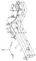
- the left and right front side frames 31, 31 obtained by bending and quenching the steel pipe W by a hot working device are arranged in the front-rear direction at the front of the vehicle body, and a bumper beam 32 is connected between the front ends.
- a bulkhead lower panel 33 that partitions the engine room and the passenger compartment is connected to the upper surface of the rear part.
- a power unit 34 in which the engine and the transmission are coupled is supported between the middle portions in the front-rear direction via left and right mount members 35, 35.
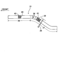
- the front side frame 31 is integrally provided with a power unit mounting portion 36 that is the first half thereof and a kick-up portion 37 that is the second half thereof.
- the kick-up portion 37 is bent at the front first bent portion 38 and the rear second bent portion 39, so that the kick-up portion 37 faces forward from the rear end of the front side frame 31 and outward in the left-right direction (vehicle width direction). It extends.
- the power unit attachment portion 36 extends substantially horizontally in a side view, but is bent convexly outward in the vehicle width direction in a plan view at a third bent portion 40 provided in the power unit attachment portion 36.
- These first to third bent portions 38, 39, and 40 are formed by bending the steel pipe W with a hot working apparatus.
- the front side frame 31 includes a first fragile portion 41 whose strength is partially reduced at the position of the second bent portion 39, and the strength is partially set at a position immediately before the third bent portion 40.
- the lowered second weakened part 42 is provided. Since the first fragile portion 41 is in the bent portion of the front side frame 31, it is formed by annealing only a part of the front side frame 31 that has been entirely quenched. On the other hand, since the second fragile portion 42 is in the straight portion of the front side frame 31, it is formed by temporarily stopping energization of the high-frequency heating coil 26 during hot working, thereby interrupting the quenching process of that portion.
- a high-frequency heating coil 26 is loosely fitted and moved on the outer periphery of a front side frame 31 obtained by bending and quenching a steel pipe W by a hot working device. Heating is performed by energizing only when passing through the positions of the first fragile portion 41 and the second fragile portion 42. Then, the first fragile portion 41 and the second fragile portion that are not subjected to the quenching process are applied to the front side frame 31 that has been subjected to the overall quenching process by gradually cooling the heating part and performing the annealing process. 42 can be formed.
- the bending moment acting on the simple support beam is zero at both ends of the support beam, and the maximum value is obtained at the point of application of the load F.
- the distribution is an isosceles triangle (see broken line).
- the solid line extending horizontally indicates the strength of the beam (the maximum bending moment that can be withstanding without bending). When the maximum value of the bending moment that increases with an increase in the load F exceeds the strength, the beam is positioned at that position. It will bend without being able to endure.
- FIG. 7B shows the front side frame 31 of the embodiment, which includes a first bent portion 38, a second bent portion 39, and a third bent portion 40.
- the axis of the side frame 31 is bent so as to protrude outward in the vehicle width direction.
- FIG. 7 (A) shows a front side frame 31 of a comparative example, which includes only the first bent portion 38 and the second bent portion 39 but does not include the third bent portion 40, but the third bent portion.
- the front side frame 31 extends linearly in the front-rear direction without bending at a position corresponding to 40.
- the load F acting on the vehicle is a resultant force of the collision load in the front-rear direction and the frictional force, and is inclined inward in the vehicle width direction.
- the load F is decomposed into an axial force in the axial direction of the front side frame 31 and a shearing force orthogonal to the axial line, and a bending moment acts on each part of the front side frame 31 according to the shearing force.
- the front power unit mounting portion 36 since the front power unit mounting portion 36 is linear, the inward shearing forces S1 ′ and S2 ′ between them are constant.
- the power unit mounting portion 36 since the power unit mounting portion 36 includes the third bent portion 40 and is bent convexly outward in the vehicle width direction, the shear force S1 is provided in front of the third bent portion 40. Increases and the shearing force S2 decreases after the third bent portion 40. Since the shape of the kick-up portion 37 is the same in the comparative example and the embodiment, the shearing force is also the same.
- the direction of the shearing forces S3 ′ and S3 is reversed so that the outer side in the vehicle width direction.
- the direction of the shearing force S4 ', S4 is reversed again at the position before the second bent portion 39 and faces inward in the vehicle width direction.
- the two solid lines in the lower graph of FIG. 7 indicate the proof stress when a rightward bending moment and a leftward bending moment are applied to the front side frame 31, and two dents in each proof stress line are It shows that the yield strength is reduced by the weakening by the first weak part 41 and the second weak part 42.
- the alternate long and two short dashes line indicates the bending moment acting on the front side frame 31 of the comparative example of FIG. 7A.
- the a position in the vicinity of the first bent portion 38 and the b position in the vicinity of the second bent portion 39 are shown. It shows that the bending moment reaches the yield strength and the front side frame 31 bends at two positions, a and b.
- the broken line indicates the bending moment acting on the front side frame 31 of the embodiment of FIG. 7B, and the bending moment increases toward the position c by increasing the shearing force of the front side portion of the third bent portion 40.
- the bending moment increases gradually from the position c to the position a due to a sharp increase and a decrease in the shearing force of the rear portion of the third bent portion 40.
- the bending moment reaches the yield strength at the position c near the third bent portion 40 and the position b near the second bent portion 39, the front side frame 31 bends, and the bending moment does not reach the yield strength at the position a. Therefore, the front side frame 31 is not bent.
- the front side frame 31 is in the vicinity of the first bent portion 38 and the second bent portion 39 of the kick-up portion 37.
- FIG. 8 (A) the shock absorbing stroke in which the front end of the front side frame 31 moves backward becomes small, and there is a possibility that sufficient shock absorbing performance cannot be obtained.
- the shock absorbing stroke in which the front end of the front side frame 31 moves backward becomes small, and there is a possibility that sufficient shock absorbing performance cannot be obtained.
- the shock absorbing stroke in which the front end of the front side frame 31 moves backward becomes small, and there is a possibility that sufficient shock absorbing performance cannot be obtained.
- the shock absorbing stroke in which the front end of the front side frame 31 is retracted is increased as shown in FIG. 8B, and sufficient shock absorbing performance can be obtained.
- the first fragile portion 41 and the second fragile portion 42 are post-processed by annealing the steel pipe W.
- the first fragile portion 41 and the second fragile portion 42 formed by the annealing process have an internal structure in which the internal stress is removed and is uniformly softened.
- the collision energy can be absorbed by the entire cross section of the first fragile portion 41 and the second fragile portion 42.
- the second fragile portion 42 is provided by being offset to the front side of the third bent portion 40.
- the fragile portion 42 is provided at the position of the third bent portion 40, and as shown in FIG. 9B, the second fragile portion 42 is offset to the rear side of the third bent portion 40 in the third embodiment. Is provided.
- the second fragile portion 42 only needs to be provided in the vicinity of the third bent portion 40, and the position of the second fragile portion 42 is changed while achieving the same effect as the first embodiment.
- the degree of freedom in designing the front side frame 31 can be increased.
- the second fragile portion 42 is provided at the position of the third bent portion 40, and heating of the third bent portion 40 cannot be stopped during hot working. Therefore, it is necessary to form the 2nd weak part 42 by annealing the 3rd bending part 40 by which the hardening process was carried out.
- the second weakened portion 42 is provided offset from the position of the third bent portion 40, and the third bent portion 40 is heated during hot working. Since it can be stopped, the second fragile portion 42 can be formed by not performing the quenching process for that portion.
- FIG. 10A the front side of the third bent portion 40 extends along the front-rear direction, and the rear side of the third bent portion 40 is inclined inward in the vehicle width direction.
- 10 (B) to 10 (D) show an embodiment including a fourth bent portion 43 in addition to the first bent portion 38, the second bent portion 39, and the third bent portion 40.
- FIG. The fifth embodiment of B) includes a fourth bent portion 43 on the front side of the third bent portion 40
- the sixth embodiment of FIG. 10C is the fourth on the rear side of the third bent portion 40.
- a bent portion 43 is provided, and the seventh embodiment of FIG.
- 10D includes two fourth bent portions 43, 43 on the front side and the rear side of the third bent portion 40.
- the eighth embodiment shown in FIG. 10E includes a fourth bent portion 43 on the rear side of the third bent portion 40, and the rear side of the fourth bent portion 43 extends along the front-rear direction.
- the front side frame 31 bends convexly outward in the vehicle width direction at the third bent portion 40, it is only possible to achieve the same function and effect as in the first embodiment.
- the fourth bent portion 43 can be provided, and the degree of freedom in designing the shape of the front side frame 31 is increased.
- FIGS. 12 and 13 the left and right front side frames 31 arranged in the front-rear direction at the front of the vehicle body integrally connect a front power unit mounting portion 36 and a rear kick-up portion 37.
- the power unit mounting portion 36 is a substantially linear member, and is disposed substantially horizontally in a side view, and is disposed in parallel with a vehicle body center line in a plan view.
- the kick-up portion 37 is a member that is bent in an approximately S shape in a side view and a plan view, and includes a front bent portion 114, an intermediate portion 115, and a rear bent portion 116 in order from the front to the rear.
- the front bent portion 114 connected to the rear end of the power unit attachment portion 36 bends downward and inward in the left-right direction (vehicle width direction) toward the rear.
- the intermediate part 115 connected to the rear end of the front bent part 114 is arranged such that the rear side is inclined downward and inward in the left-right direction (vehicle width direction).
- the rear bent portion 116 connected to the rear end of the intermediate portion 115 is bent rearward upward and in the left-right direction (vehicle width direction), and is disposed substantially horizontally in a side view and parallel to the vehicle body center line in a plan view.
- the power unit attachment portion 36 of the front side frame 31 is formed by rolling the first tubular hollow member 117 and the second tubular hollow member 118 formed in a polygonal (trapezoid with the upper bottom down) by roll forming a steel plate. Overlaid in the direction and connected by welding. Further, the kick-up portion 37 of the front side frame 31 is formed in a closed cross section by welding first to third sheet metal members 119, 120, and 121 obtained by press-working steel plates.
- FIG. 14 shows cross-sectional shapes of the front side frame 31 at six positions A to F.
- the position A corresponds to the power unit mounting portion 36, and the position B is in front of the front bent portion 114 of the kick-up portion 37.
- Position C corresponds to the rear part of the front bent part 114 of the kick-up part 37
- position D corresponds to the front part of the intermediate part 115 of the kick-up part 37
- position E corresponds to the middle part of the kick-up part 37.
- the position F corresponds to the rear portion of the portion 115
- the position F corresponds to the rear bent portion 116 of the kick-up portion 37.
- the cross section of the power unit mounting portion 36 corresponding to the position A is obtained by superposing the second tubular hollow member 118 having a trapezoidal section tapering downward on the lower side of the first tubular hollow member 117 having a trapezoidal section tapering downward.
- a trapezoidal cross section is formed which tapers downward as a whole.
- the aspect ratio ⁇ of the cross section at the position A that is, (height b) / (horizontal direction width a) is larger than 1, and thus has a vertically long cross section.
- the first and second tubular hollow members 117 and 118 each have four ridge lines, the strength is enhanced by the ridge lines.
- a cross section of the front portion of the front bent portion 114 of the kick-up portion 37 corresponding to the position B is a second sheet metal member having a groove-shaped cross section that opens upward in an opening portion of the first sheet metal member 119 having a groove-shaped cross section that opens upward.
- the bottom part of 120 is welded, and further, a flat plate-like third sheet metal member 121 is welded to the opening of the second sheet metal member 120, and a trapezoidal cross section is formed that tapers downward in the same manner as the position A. .
- the rear end of the power unit mounting portion 36 is inserted into the front end of the kick-up portion 37 and is integrally coupled by welding.
- the eight ridge lines of the first and second tubular hollow members 117 and 118 and the six ridge lines of the first to third sheet metal members 119 to 121 are connected in series, thereby kicking from the power unit mounting portion 36.
- the strength of the front side frame 31 can be increased by smoothly transmitting the load to the up portion 37.
- the cross section of the rear portion of the front bent portion 114 of the kick-up portion 37 corresponding to the position C is basically the same as the cross section of the position B described above, but the aspect ratio ⁇ decreases due to the decrease in the height.
- the cross section of the front portion of the intermediate portion 115 corresponding to the position D has a second sheet metal member 120 that has a flat shape in the opening portion of the first sheet metal member 119 having a groove-shaped cross section that opens upward with an increase in width in the left-right direction.
- the third sheet metal member 121 having a hat shape is welded to the upper surface of the second sheet metal member 120, and the aspect ratio ⁇ is changed to a horizontally long cross-sectional shape smaller than 1.
- the cross section of the rear portion of the intermediate portion 115 corresponding to the position E is the third sheet metal member 1121 that is cut off from the cross section of the position D, and is changed to a horizontally long cross-sectional shape with a smaller aspect ratio ⁇ .
- the height of the first sheet metal member 119 is increased and the aspect ratio ⁇ is slightly increased as compared with the cross section of the position E. Further, a bead 120 a that is recessed downward is formed at the center in the width direction of the second sheet metal member 120.
- the axial force is high in the entire power unit mounting portion 36 (position A) and in the front portion (position B) of the front bent portion 114 of the kick-up portion 37, and in the rear portion (position C) and intermediate portion of the front bent portion 114.
- 115 is moderately reduced at the front portion (position D) of 115, and is lowered at the rear portion (position E) and the rear bent portion 116 (position F) of the intermediate portion 115.
- the absolute value of the left / right bending moment changes from a low state to a high state in the entire region of the power unit mounting portion 36 (position A), and the front portion (position B) of the front bent portion 114 and the rear portion (position C) of the front bent portion 114. ) At the front portion (position D) of the intermediate portion 115, at the rear portion (position E) of the intermediate portion 115, and at the rear bent portion 116 (position F).
- the absolute value of the vertical bending moment changes from a low state to a high state in the entire region (position A) of the power unit mounting portion 36, becomes high at the front portion (position B) of the front side bending portion 114, and the rear portion of the front bending portion 114. It becomes medium at (position C), becomes lower at the front part (position D) of the intermediate part 115 and the rear part (position E) of the intermediate part 115, and becomes higher at the rear bent part 116 (position F).
- each part of the front side frame 31 is set according to changes in the above-described axial force, left-right bending moment, and up-down bending moment.
- the first tubular hollow member 117 and the second tubular hollow member 118 each having four ridge lines in total of four correspond to a high axial force.
- the front portion (position B) of the front bent portion 114 of the kick-up portion 37 a total of four ridgelines of the first to third sheet metal members 119 to 121 and a total of four of the first to third sheet metal members 119 to 121 are provided.
- High axial force is supported by the flange joint of the book.
- the rear portion (position C) of the front bent portion 114 the height of the cross section is reduced in accordance with the decrease in the vertical bending moment to reduce the weight.
- the horizontal width of the cross section is increased in accordance with the increase in the left and right bending moment, and the height of the cross section is decreased in accordance with the decrease in the vertical bending moment, whereby the aspect ratio is increased. ⁇ is decreased.
- the third sheet metal member 121 is eliminated to reduce the weight.
- the rear bent portion 116 since the vertical bending moment increases, the height of the cross section is increased, and the second sheet metal member 120 on the compression side is provided with a bead 120a.
- FIG. 15 is a graph showing how the input / proof force ratio of the front side frame 31 changes in its longitudinal direction, and the solid line shows the case where the entire front side frame 31 is configured by a tubular hollow member, A broken line indicates a case where the entire front side frame 31 is formed of a sheet metal member.
- the input is a collision load applied to the front side frame 31 when the automobile collides with the front
- the proof stress is a load that the front side frame 31 can withstand without bending.
- the front side frame 31 is bent at that position and absorbs the collision energy.
- the front side frame 31 is bent at three positions indicated by a, b, and c.
- the front side frame 31 is prevented from being bent with a 20% margin by suppressing the input / proof strength to about 80%.
- the input / proof strength is significantly lower than 80%, the front side frame 31 has excessive strength and the weight is unnecessarily increased. Therefore, the input / proof strength is slightly lower than 80%. It is desirable.
- the entire front side frame 31 is formed of a tubular hollow member (see the solid line)
- the strength is excessive at the d and e positions of the kick-up portion 37, and the input / proof strength is much higher than 80%. It can be seen that the weight decreases and the weight increases uselessly.
- the entire front side frame 31 is composed of a sheet metal member (see the broken line)
- the strength is insufficient at the position f at the rear end of the power unit mounting portion 36, and the input / proof strength greatly exceeds 80%.
- the front side frame 31 may be bent at the position f.
- the power unit mounting portion 36 of the front side frame 31 is configured by a tubular hollow member, and the kick-up portion 37 of the front side frame 31 is configured by a sheet metal member, whereby the front side frame 31 is a, b, While securing the strength distribution for bending at the three points c, it is possible to prevent the strength of other portions of the front side frame 31 from becoming excessive and to reduce the weight to the maximum.
- the power unit attachment portion 36 and the kick-up portion 37 of the front side frame 31 have different axial force and moment change characteristics acting thereon.
- the first to third sheet metal members 119 to 121 are combined with a fine strength in the kick-up portion 37 in which the moment changes rapidly while ensuring the necessary strength with the first tubular hollow member 1117 and the second tubular hollow member 118 having ridge lines.
- the strength of the front side frame 31 can be reduced by preventing the strength from becoming excessive.
- the structure of the front side frame 31 of the tenth embodiment is basically the same as that of the front side frame 31 of the ninth embodiment, and includes a power unit mounting portion 36 that extends in a straight line on the front side, and an S on the rear side. It is comprised with the kick-up part 37 bent in a letter shape.
- the kick-up portion 37 of the front side frame of the ninth embodiment is composed of the first to third sheet metal members 119 to 121 having the same plate thickness, whereas the front side of the tenth embodiment.
- the kick-up portion 37 of the frame 31 is composed of first to third sheet metal members 119 to 121 having different sheet thicknesses, and the sheet thickness of the first sheet metal member 119 is that of the second sheet metal member 120 and the third sheet metal member 1121. It differs in that it is set thicker than the plate thickness.
- the cross section at the position A of the power unit attachment portion 36 is configured by joining the first tubular hollow member 117 and the second tubular hollow member 118 in the vertical direction by welding, but the left and right widths of the lower surface of the first tubular hollow member 117 Is larger than the lateral width of the upper surface of the second tubular hollow member 118, and a step is formed at the joint.
- the cross section at the position B and the position C of the kick-up portion 37 is obtained by welding the flat plate-shaped second sheet metal member 120 to the opening portion of the first sheet metal member 119 having a groove-shaped cross section with stepped portions 119a and 119a opening upward. Configured. Both of the aspect ratios ⁇ are larger than 1, and the cross-sectional shape is vertically long.
- the cross section at the position D of the kick-up portion 37 is similarly formed by welding the first sheet metal member 119 and the second sheet metal member 120.
- the height of the first sheet metal member 119 is abruptly decreased and a step portion 119a is formed.
- 119a have also disappeared, and the second sheet metal member 120 has changed into a hat shape.
- the aspect ratio ⁇ is smaller than 1, and the cross-sectional shape is changed to be horizontally long.
- the first sheet metal member 119 having a further reduced height is superimposed on the inside of the third sheet metal member 1121 having a groove-shaped cross section that opens upward.
- the flat part of the second sheet metal member 120 is welded to the openings 119 and 121.
- the aspect ratio ⁇ is minimized at this position.
- the cross section at the position F of the kick-up portion 37 is formed by welding the first sheet metal member 119 changed from a groove-shaped cross section to a flat plate shape to the opening of the third sheet metal member 1121 having a groove-shaped cross section that opens upward.
- the first sheet metal member 119 is provided with two beads 119b and 119b extending in the front-rear direction.
- the aspect ratio ⁇ has started to increase, but is still smaller than 1.
- the first to third sheet metal members 119 to 121 have a total of six ridge lines in the ninth embodiment, whereas the first and second sheet metal members 119 in the tenth embodiment. , 120 includes only four ridge lines in total, so that it is possible to withstand high axial force by forming step portions 119a, 119a on the side surface of the first sheet metal member 119 to increase rigidity.
- a thick plate is used for the first sheet metal member 119 on the compression side so that it can withstand a large downward bending moment.
- a thick plate is used for the third sheet metal member 119 on the compression side and two beads 119b and 119b are formed so as to withstand a large upward bending moment.
- the first fragile portion 41 and the second fragile portion 42 are formed by annealing, but they may be formed by openings, notches, bent beads, or the like.
- the cross-sectional shape of the first and second tubular hollow members 117 and 118 is not limited to a trapezoidal shape, and may be a rectangular or square polygon, or a closed cross-section other than a polygon.
- the number of sheet metal members constituting the kick-up portion 37 is not limited to three in the embodiment, and may be plural.
Landscapes
- Engineering & Computer Science (AREA)
- Chemical & Material Sciences (AREA)
- Mechanical Engineering (AREA)
- Combustion & Propulsion (AREA)
- Transportation (AREA)
- Crystallography & Structural Chemistry (AREA)
- Physics & Mathematics (AREA)
- Thermal Sciences (AREA)
- General Engineering & Computer Science (AREA)
- Materials Engineering (AREA)
- Metallurgy (AREA)
- Organic Chemistry (AREA)
- Architecture (AREA)
- Structural Engineering (AREA)
- Body Structure For Vehicles (AREA)
- Heat Treatment Of Articles (AREA)
- Bending Of Plates, Rods, And Pipes (AREA)
Abstract
Description
11 鋼管送出装置
13 高周波加熱コイル
14 冷却装置
15 曲げ装置
31 フロントサイドフレーム
34 パワーユニット
36 パワーユニット取付部
37 キックアップ部
38 第1屈曲部
39 第2屈曲部
40 第3屈曲部
41 第1脆弱部
42 第2脆弱部
43 第4屈曲部(他の屈曲部)
114 前側屈曲部
115 中間部
116 後側屈曲部
117 第1管状中空部材(管状中空部材)
118 第2管状中空部材(管状中空部材)
119 第1板金部材(板金部材)
120 第2板金部材(板金部材)
121 第3板金部材(板金部材)
λ 縦横比
[第2および第3の実施の形態]
第1の実施の形態では、第2脆弱部42が第3屈曲部40の前側にオフセットして設けられているが、図9(A)に示すように、第2の実施の形態では第2脆弱部42が第3屈曲部40の位置に設けられており、図9(B)に示すように、第3の実施の形態では第2脆弱部42が第3屈曲部40の後側にオフセットして設けられている。すなわち、第2脆弱部42は第3屈曲部40の近傍に設けられていれば良く、第1の実施の形態と同様の作用効果を達成しながら、第2脆弱部42の位置を変化させてフロントサイドフレーム31の設計自由度を高めることができる。
[第4~第8の実施の形態]
図10(A)に示す第4の実施の形態は、第3屈曲部40の前側が前後方向に沿って延び、第3屈曲部40の後側が車幅方向内側に傾斜している。図10(B)~図10(D)は、1屈曲部38、第2屈曲部39および第3屈曲部40に加えて第4屈曲部43を備える実施の形態を示すもので、図10(B)の第5の実施の形態は第3屈曲部40の前側に第4屈曲部43を備え、図10(C)の第6の実施の形態は第3屈曲部40の後側に第4屈曲部43を備え、図10(D)の第7の実施の形態は第3屈曲部40の前側および後側に二つの第4屈曲部43,43を備えている。図10(E)に示す第8の実施の形態は、第3屈曲部40の後側に第4屈曲部43を備え、第4屈曲部43の後側が前後方向に沿って延びている。
[第9の実施の形態]
図12および図13に示すように、自動車の車体前部に前後方向に配置される左右のフロントサイドフレーム31は、前側のパワーユニット取付部36と後側のキックアップ部37とを一体に連結して構成される。パワーユニット取付部36は概ね直線状の部材であって、側面視で略水平に配置され、平面視で車体中心線と平行に配置される。キックアップ部37は側面視および平面視で概ねS字状に屈曲する部材であって、前から後に向かって順番に前側屈曲部114、中間部115および後側屈曲部116を備える。パワーユニット取付部36の後端に接続される前側屈曲部114は、後方に向かって下方および左右方向(車幅方向)内側に屈曲する。前側屈曲部114の後端に連なる中間部115は、後方側が下方および左右方向(車幅方向)内側に傾斜して配置される。中間部115の後端に連なる後側屈曲部116は、後方に向かって上方および左右方向(車幅方向)外側に屈曲し、側面視で略水平かつ平面視で車体中心線と平行に配置される。
[第10の実施の形態]
第10の実施の形態のフロントサイドフレーム31の構造は、基本的に第9の実施の形態のフロントサイドフレーム31と同じであり、前側の直線状に伸びるパワーユニット取付部36と、後側のS字状に屈曲するキックアップ部37とで構成される。但し、第9の実施の形態のフロントサイドフレームのキックアップ部37が同一板厚の第1~第3板金部材119~121で構成されているのに対し、第10の実施の形態のフロントサイドフレーム31のキックアップ部37は板厚が異なる第1~第3板金部材119~121で構成されるもので、第1板金部材119の板厚が第2板金部材120および第3板金部材1121の板厚よりも厚く設定されている点で異なっている。
Claims (11)
- 車体前部に前後方向に配置されるフロントサイドフレーム(31)が一定断面を有する管状中空部材で構成され、前記フロントサイドフレーム(31)はパワーユニット(34)が取り付けられるパワーユニット取付部(36)の後方に前側の第1屈曲部(38)と後側の第2屈曲部(39)とを備える自動車のフロントサイドフレーム構造において、
前記フロントサイドフレーム(31)は前記パワーユニット取付部(36)の前方に車幅方向外側に凸に屈曲する第3屈曲部(40)を備え、前記第2屈曲部(39)の近傍に該フロントサイドフレーム(31)の他の部分に比べて脆弱な第1脆弱部(41)が形成されるとともに、前記第3屈曲部(40)の近傍に該フロントサイドフレーム(31)の他の部分に比べて脆弱な第2脆弱部(42)が形成されることを特徴とする自動車のフロントサイドフレーム構造。 - 前記フロントサイドフレーム(31)は焼き入れ処理により強度が高められることを特徴とする、請求項1に記載の自動車のフロントサイドフレーム構造。
- 前記フロントサイドフレーム(31)は前記第3屈曲部(40)の前方あるいは後方に更に他の屈曲部(43)を備えることを特徴とする、請求項1または請求項2に記載の自動車のフロントサイドフレーム構造。
- 前記第3屈曲部(40)の近傍の第2脆弱部(42)は、該第3屈曲部(40)の位置から前方あるいは後方にオフセットしていることを特徴とする、請求項1~請求項3の何れか1項に記載の自動車のフロントサイドフレーム構造。
- 前記フロントサイドフレーム(31)は、鋼管送出装置(11)から鋼管(W)を長手方向に沿って送出し、前記鋼管送出装置(11)から送出された前記鋼管(W)を高周波加熱コイル(13)で加熱し、前記高周波加熱コイル(13)で加熱された前記鋼管(W)を曲げ装置(15)で曲げ加工し、前記曲げ装置(15)で曲げ加工された鋼管(W)を冷却装置(14)で冷却して焼き入れ処理することで製造されることを特徴とする、請求項1~請求項4の何れか1項に記載の自動車のフロントサイドフレーム構造。
- 前記第2脆弱部(42)は前記第3屈曲部(40)上にあり、前記第2脆弱部(42)は焼き入れ処理された前記フロントサイドフレーム(31)の一部を焼き鈍し処理することで形成されることを特徴とする、請求項5に記載の自動車のフロントサイドフレーム構造。
- 前記パワーユニット取付部(36)は2本の管状中空部材(117,118)を上下に重ね合わせて構成され、前記キックアップ部(37)は少なくとも2個の板金部材(119~121)を組み合わせて閉断面に構成されることを特徴とする、請求項1に記載の自動車のフロントサイドフレーム構造。
- 前記管状中空部材(117,118)は多角形断面を有することを特徴とする、請求項7に記載の自動車のフロントサイドフレーム構造。
- 前記管状中空部材(117,118)の稜線に前記板金部材(119~121)の稜線を接続したことを特徴とする、請求項8に記載の自動車のフロントサイドフレーム構造。
- 前記キックアップ部(37)は前側の第1屈曲部(114)と後側の第2屈曲部(116)とを有してS字状に屈曲し、前記第1、第2屈曲部(114,116)に挟まれた中間部(115)の縦横比(λ)は1未満であることを特徴とする、請求項7~請求項9の何れか1項に記載の自動車のフロントサイドフレーム構造。
- 前記中間部(115)から前記第2屈曲部(116)に向かって前記縦横比(λ)が増加することを特徴とする、請求項10に記載の自動車のフロントサイドフレーム構造。
Priority Applications (4)
| Application Number | Priority Date | Filing Date | Title |
|---|---|---|---|
| US13/983,678 US9211913B2 (en) | 2011-02-09 | 2012-01-27 | Structure for front side frames of automobile |
| EP12744661.5A EP2657110A4 (en) | 2011-02-09 | 2012-01-27 | STRUCTURE FOR SIDE FRAMES BEFORE AUTOMOTIVE |
| JP2012556829A JP5749748B2 (ja) | 2011-02-09 | 2012-01-27 | 自動車のフロントサイドフレーム構造 |
| CN201280006270.2A CN103328312B (zh) | 2011-02-09 | 2012-01-27 | 汽车的前侧车架构造 |
Applications Claiming Priority (4)
| Application Number | Priority Date | Filing Date | Title |
|---|---|---|---|
| JP2011-026085 | 2011-02-09 | ||
| JP2011026085 | 2011-02-09 | ||
| JP2011028503 | 2011-02-14 | ||
| JP2011-028503 | 2011-02-14 |
Publications (1)
| Publication Number | Publication Date |
|---|---|
| WO2012108282A1 true WO2012108282A1 (ja) | 2012-08-16 |
Family
ID=46638499
Family Applications (1)
| Application Number | Title | Priority Date | Filing Date |
|---|---|---|---|
| PCT/JP2012/051805 WO2012108282A1 (ja) | 2011-02-09 | 2012-01-27 | 自動車のフロントサイドフレーム構造 |
Country Status (5)
| Country | Link |
|---|---|
| US (1) | US9211913B2 (ja) |
| EP (1) | EP2657110A4 (ja) |
| JP (1) | JP5749748B2 (ja) |
| CN (1) | CN103328312B (ja) |
| WO (1) | WO2012108282A1 (ja) |
Cited By (4)
| Publication number | Priority date | Publication date | Assignee | Title |
|---|---|---|---|---|
| GB2505669A (en) * | 2012-09-06 | 2014-03-12 | Secr Defence | Chassis frame deformable on under vehicle impact |
| JP2014159037A (ja) * | 2013-02-20 | 2014-09-04 | Honda Motor Co Ltd | 鋼管の熱間加工装置 |
| WO2015156052A1 (ja) * | 2014-04-11 | 2015-10-15 | 本田技研工業株式会社 | 自動車の車体構造 |
| JPWO2022208744A1 (ja) * | 2021-03-31 | 2022-10-06 |
Families Citing this family (18)
| Publication number | Priority date | Publication date | Assignee | Title |
|---|---|---|---|---|
| CN103402857A (zh) * | 2011-03-10 | 2013-11-20 | 本田技研工业株式会社 | 汽车的车身架构造 |
| WO2012160697A1 (ja) * | 2011-05-26 | 2012-11-29 | トヨタ自動車株式会社 | ヘッダエクステンションの成形方法及び車体構造 |
| JP5549791B1 (ja) * | 2012-09-21 | 2014-07-16 | 新日鐵住金株式会社 | 高周波誘導加熱装置、加工装置 |
| WO2015093621A2 (en) * | 2013-12-19 | 2015-06-25 | Neturen Co., Ltd. | Induction heating coil and induction heating method |
| JP6140848B2 (ja) * | 2014-02-12 | 2017-05-31 | 本田技研工業株式会社 | 車体前部構造 |
| EP3162672A4 (en) * | 2014-06-26 | 2018-01-24 | Nippon Steel & Sumitomo Metal Corporation | Structural member for automobile body |
| JP6239124B2 (ja) * | 2014-08-04 | 2017-12-06 | 本田技研工業株式会社 | 車体構造 |
| US9365241B1 (en) * | 2015-03-04 | 2016-06-14 | Honda Motor Co., Ltd. | Vehicle crash management apparatus and methods of use and manufacture thereof |
| JP6398797B2 (ja) * | 2015-03-05 | 2018-10-03 | トヨタ紡織株式会社 | 乗物用シート |
| KR101714884B1 (ko) * | 2015-07-27 | 2017-03-10 | 주식회사 포스코 | 자동차용 프런트 사이드 프레임 |
| CN109311070A (zh) * | 2016-06-09 | 2019-02-05 | 戴弗根特技术有限公司 | 用于弧形件和节点的设计和制造的系统及方法 |
| DE102016114068B3 (de) * | 2016-07-29 | 2017-08-10 | Benteler Automobiltechnik Gmbh | Längsträger aus Mehrlagenstahl |
| WO2018025565A1 (ja) * | 2016-08-02 | 2018-02-08 | 本田技研工業株式会社 | 車体構造 |
| US10259501B2 (en) | 2017-01-18 | 2019-04-16 | Ford Global Technologies, Llc | Vehicle frame |
| US10272948B2 (en) * | 2017-06-16 | 2019-04-30 | Ford Global Technologies, Llc | Front rail for vehicle underbody assembly with varied strength zones |
| EP3760330A4 (en) * | 2018-02-28 | 2021-04-14 | JFE Steel Corporation | METAL PLATE FOR PRESS FORMING, PRESS FORM DEVICE AND MANUFACTURING METHOD FOR PRESSED COMPONENTS |
| JP7053431B2 (ja) * | 2018-10-24 | 2022-04-12 | 本田技研工業株式会社 | 車体後部構造 |
| CN112009568B (zh) * | 2019-05-30 | 2022-10-28 | 马自达汽车株式会社 | 车辆的动力系支撑结构 |
Citations (11)
| Publication number | Priority date | Publication date | Assignee | Title |
|---|---|---|---|---|
| JPS49133323U (ja) * | 1973-03-17 | 1974-11-15 | ||
| JPS5747480U (ja) * | 1980-08-27 | 1982-03-16 | ||
| JPS6467482A (en) * | 1987-09-04 | 1989-03-14 | Mazda Motor | Automobile frame structure |
| JPH0986438A (ja) * | 1995-09-22 | 1997-03-31 | Nissan Motor Co Ltd | 車体強度部材の補強構造 |
| JP2003095132A (ja) * | 2001-09-21 | 2003-04-03 | Mazda Motor Corp | 車体のフレーム構造及び車体フレームの製造方法 |
| JP2004083931A (ja) * | 2002-08-22 | 2004-03-18 | Mazda Motor Corp | 車体の強度部材、車体の強度部材構造及び車体強度部材の製造方法 |
| JP2004188998A (ja) * | 2002-12-06 | 2004-07-08 | Honda Motor Co Ltd | 車体フレーム |
| JP2004352092A (ja) * | 2003-05-29 | 2004-12-16 | Fuji Heavy Ind Ltd | 車体のフレーム構造 |
| JP2007112212A (ja) * | 2005-10-18 | 2007-05-10 | Fuji Heavy Ind Ltd | 車体フレーム構造 |
| JP2008105517A (ja) * | 2006-10-25 | 2008-05-08 | Calsonic Kansei Corp | バンパステイ構造 |
| WO2008123505A1 (ja) * | 2007-04-04 | 2008-10-16 | Sumitomo Metal Industries, Ltd. | 曲げ加工製品の製造方法、製造装置及び連続製造装置 |
Family Cites Families (27)
| Publication number | Priority date | Publication date | Assignee | Title |
|---|---|---|---|---|
| JPS5029209B2 (ja) * | 1971-12-08 | 1975-09-22 | ||
| DE2261926C3 (de) | 1972-12-18 | 1978-11-30 | Deutsche Gold- Und Silber-Scheideanstalt Vormals Roessler, 6000 Frankfurt | Verfahren zur Herstellung von DL-Methionyl-DL-methionin |
| US4399221A (en) | 1980-07-05 | 1983-08-16 | Fisons Limited | Enzyme production and purification |
| JPS5758561A (en) * | 1980-09-22 | 1982-04-08 | Nissan Motor Co Ltd | Collision energy damping structure of vehicle |
| CA2280440C (en) * | 1998-08-17 | 2005-01-18 | Masayoshi Okamoto | Automotive vehicle body structure demonstrating a controlled reaction load |
| JP2000233765A (ja) * | 1999-02-17 | 2000-08-29 | Suzuki Motor Corp | 自動車の前部フレーム構造 |
| JP2001188998A (ja) * | 1999-12-28 | 2001-07-10 | Yokohama Tokushu Senpaku Co Ltd | 車輌のレンタルシステム及びレンタル方法 |
| CA2439821C (en) | 2001-03-02 | 2009-06-30 | Magna International Inc. | Hybrid space frame for motor vehicule |
| JP4019647B2 (ja) * | 2001-03-28 | 2007-12-12 | 三菱自動車工業株式会社 | 車体構造 |
| DE10208778B4 (de) * | 2002-02-28 | 2004-08-12 | Thyssenkrupp Stahl Ag | Aus Stahl-Hohlprofilen gebildete Tragstruktur für Fahrzeuge |
| JP4000951B2 (ja) * | 2002-08-13 | 2007-10-31 | 三菱自動車エンジニアリング株式会社 | 自動車の車体前部構造 |
| JP3722124B2 (ja) * | 2003-01-24 | 2005-11-30 | 日産自動車株式会社 | 車体前部構造 |
| JP2005225253A (ja) * | 2004-02-10 | 2005-08-25 | Fuji Heavy Ind Ltd | 車体フレーム構造 |
| JP2007045261A (ja) * | 2005-08-08 | 2007-02-22 | Toyota Motor Corp | 車体前部構造 |
| FR2904954A1 (fr) * | 2006-08-16 | 2008-02-22 | Renault Sas | Element de structure d'un vehicule automobile |
| CN103101576B (zh) | 2007-04-04 | 2016-03-30 | 新日铁住金株式会社 | 前纵梁 |
| JP5029328B2 (ja) | 2007-12-05 | 2012-09-19 | マツダ株式会社 | 自動車の前部車体構造 |
| JP5231877B2 (ja) * | 2008-06-19 | 2013-07-10 | 本田技研工業株式会社 | 車両用動力源の支持構造 |
| JP4653210B2 (ja) * | 2008-11-12 | 2011-03-16 | 本田技研工業株式会社 | 車体前部構造 |
| CN201580438U (zh) * | 2009-12-04 | 2010-09-15 | 中国第一汽车集团公司 | 轿车用焊接梯形车架 |
| US8201875B2 (en) * | 2010-05-19 | 2012-06-19 | Ford Global Technologies, Llc | Sub-frame for managing crash energy |
| JP5222374B2 (ja) | 2011-01-20 | 2013-06-26 | 本田技研工業株式会社 | 車体前部構造 |
| CN103402857A (zh) * | 2011-03-10 | 2013-11-20 | 本田技研工业株式会社 | 汽车的车身架构造 |
| US9145170B2 (en) * | 2011-10-25 | 2015-09-29 | Toyota Jidosha Kabushiki Kaisha | Framework member |
| JP5958005B2 (ja) * | 2012-03-26 | 2016-07-27 | マツダ株式会社 | 自動車のフロントサブフレーム構造 |
| JP5468101B2 (ja) * | 2012-03-27 | 2014-04-09 | 富士重工業株式会社 | 車体前部構造 |
| JP5949600B2 (ja) * | 2013-03-05 | 2016-07-06 | マツダ株式会社 | 車両の前部車体構造 |
-
2012
- 2012-01-27 EP EP12744661.5A patent/EP2657110A4/en not_active Withdrawn
- 2012-01-27 US US13/983,678 patent/US9211913B2/en active Active
- 2012-01-27 CN CN201280006270.2A patent/CN103328312B/zh active Active
- 2012-01-27 WO PCT/JP2012/051805 patent/WO2012108282A1/ja active Application Filing
- 2012-01-27 JP JP2012556829A patent/JP5749748B2/ja not_active Expired - Fee Related
Patent Citations (11)
| Publication number | Priority date | Publication date | Assignee | Title |
|---|---|---|---|---|
| JPS49133323U (ja) * | 1973-03-17 | 1974-11-15 | ||
| JPS5747480U (ja) * | 1980-08-27 | 1982-03-16 | ||
| JPS6467482A (en) * | 1987-09-04 | 1989-03-14 | Mazda Motor | Automobile frame structure |
| JPH0986438A (ja) * | 1995-09-22 | 1997-03-31 | Nissan Motor Co Ltd | 車体強度部材の補強構造 |
| JP2003095132A (ja) * | 2001-09-21 | 2003-04-03 | Mazda Motor Corp | 車体のフレーム構造及び車体フレームの製造方法 |
| JP2004083931A (ja) * | 2002-08-22 | 2004-03-18 | Mazda Motor Corp | 車体の強度部材、車体の強度部材構造及び車体強度部材の製造方法 |
| JP2004188998A (ja) * | 2002-12-06 | 2004-07-08 | Honda Motor Co Ltd | 車体フレーム |
| JP2004352092A (ja) * | 2003-05-29 | 2004-12-16 | Fuji Heavy Ind Ltd | 車体のフレーム構造 |
| JP2007112212A (ja) * | 2005-10-18 | 2007-05-10 | Fuji Heavy Ind Ltd | 車体フレーム構造 |
| JP2008105517A (ja) * | 2006-10-25 | 2008-05-08 | Calsonic Kansei Corp | バンパステイ構造 |
| WO2008123505A1 (ja) * | 2007-04-04 | 2008-10-16 | Sumitomo Metal Industries, Ltd. | 曲げ加工製品の製造方法、製造装置及び連続製造装置 |
Non-Patent Citations (1)
| Title |
|---|
| See also references of EP2657110A4 * |
Cited By (7)
| Publication number | Priority date | Publication date | Assignee | Title |
|---|---|---|---|---|
| GB2505669A (en) * | 2012-09-06 | 2014-03-12 | Secr Defence | Chassis frame deformable on under vehicle impact |
| JP2014159037A (ja) * | 2013-02-20 | 2014-09-04 | Honda Motor Co Ltd | 鋼管の熱間加工装置 |
| WO2015156052A1 (ja) * | 2014-04-11 | 2015-10-15 | 本田技研工業株式会社 | 自動車の車体構造 |
| JPWO2015156052A1 (ja) * | 2014-04-11 | 2017-04-13 | 本田技研工業株式会社 | 自動車の車体構造 |
| JPWO2022208744A1 (ja) * | 2021-03-31 | 2022-10-06 | ||
| WO2022208744A1 (ja) * | 2021-03-31 | 2022-10-06 | 日本製鉄株式会社 | 中空屈曲部材の製造方法及び中空屈曲部材の製造装置 |
| JP7541269B2 (ja) | 2021-03-31 | 2024-08-28 | 日本製鉄株式会社 | 中空屈曲部材の製造方法及び中空屈曲部材の製造装置 |
Also Published As
| Publication number | Publication date |
|---|---|
| EP2657110A1 (en) | 2013-10-30 |
| CN103328312B (zh) | 2016-01-27 |
| US20140015280A1 (en) | 2014-01-16 |
| JP5749748B2 (ja) | 2015-07-15 |
| EP2657110A4 (en) | 2015-07-22 |
| CN103328312A (zh) | 2013-09-25 |
| JPWO2012108282A1 (ja) | 2014-07-03 |
| US9211913B2 (en) | 2015-12-15 |
Similar Documents
| Publication | Publication Date | Title |
|---|---|---|
| WO2012108282A1 (ja) | 自動車のフロントサイドフレーム構造 | |
| US9108680B2 (en) | Automobile chassis frame structure | |
| JP5730285B2 (ja) | 車両用のエネルギ吸収サイドレール | |
| RU2573117C2 (ru) | Система управления столкновением с препятствием и способ ее изготовления (варианты) | |
| JP6581599B2 (ja) | 車体フレーム | |
| US20110233946A1 (en) | Cross member | |
| JP5168023B2 (ja) | バンパーリインフォースメントおよびその製造方法 | |
| US20140070552A1 (en) | Bumper | |
| WO2017170561A1 (ja) | 金属管、及び金属管を用いた構造部材 | |
| JP5695454B2 (ja) | 車体フレームの製造方法 | |
| US11299117B2 (en) | Energy absorbing device | |
| JP5884955B1 (ja) | 自動車車体用構造部材 | |
| JP2010179832A (ja) | 車両用バンパ装置 | |
| US11821053B2 (en) | System for conditioning material using a laser and method thereof | |
| US20110233968A1 (en) | Transmission tunnel | |
| US10538213B2 (en) | Vehicle frame member | |
| CN108367785A (zh) | 具有加强件的硬化uhss结构梁及制造方法 | |
| CN108290610A (zh) | 具有盖板的结构梁及制造方法 | |
| JP6179700B1 (ja) | 金属管、及び金属管を用いた構造部材 | |
| JPH0612137U (ja) | 自動車の車体補強用部材 |
Legal Events
| Date | Code | Title | Description |
|---|---|---|---|
| 121 | Ep: the epo has been informed by wipo that ep was designated in this application |
Ref document number: 12744661 Country of ref document: EP Kind code of ref document: A1 |
|
| ENP | Entry into the national phase |
Ref document number: 2012556829 Country of ref document: JP Kind code of ref document: A |
|
| WWE | Wipo information: entry into national phase |
Ref document number: 2012744661 Country of ref document: EP |
|
| NENP | Non-entry into the national phase |
Ref country code: DE |
|
| WWE | Wipo information: entry into national phase |
Ref document number: 13983678 Country of ref document: US |