WO2012060123A1 - 電動式パワーステアリング用パワーモジュールおよびこれを用いた電動式パワーステアリング駆動制御装置 - Google Patents
電動式パワーステアリング用パワーモジュールおよびこれを用いた電動式パワーステアリング駆動制御装置 Download PDFInfo
- Publication number
- WO2012060123A1 WO2012060123A1 PCT/JP2011/060056 JP2011060056W WO2012060123A1 WO 2012060123 A1 WO2012060123 A1 WO 2012060123A1 JP 2011060056 W JP2011060056 W JP 2011060056W WO 2012060123 A1 WO2012060123 A1 WO 2012060123A1
- Authority
- WO
- WIPO (PCT)
- Prior art keywords
- power
- power module
- motor
- control device
- electric power
- Prior art date
Links
Images


Classifications
-
- B—PERFORMING OPERATIONS; TRANSPORTING
- B62—LAND VEHICLES FOR TRAVELLING OTHERWISE THAN ON RAILS
- B62D—MOTOR VEHICLES; TRAILERS
- B62D5/00—Power-assisted or power-driven steering
- B62D5/04—Power-assisted or power-driven steering electrical, e.g. using an electric servo-motor connected to, or forming part of, the steering gear
- B62D5/0403—Power-assisted or power-driven steering electrical, e.g. using an electric servo-motor connected to, or forming part of, the steering gear characterised by constructional features, e.g. common housing for motor and gear box
- B62D5/0406—Power-assisted or power-driven steering electrical, e.g. using an electric servo-motor connected to, or forming part of, the steering gear characterised by constructional features, e.g. common housing for motor and gear box including housing for electronic control unit
-
- B—PERFORMING OPERATIONS; TRANSPORTING
- B62—LAND VEHICLES FOR TRAVELLING OTHERWISE THAN ON RAILS
- B62D—MOTOR VEHICLES; TRAILERS
- B62D5/00—Power-assisted or power-driven steering
- B62D5/04—Power-assisted or power-driven steering electrical, e.g. using an electric servo-motor connected to, or forming part of, the steering gear
- B62D5/0409—Electric motor acting on the steering column
-
- H—ELECTRICITY
- H01—ELECTRIC ELEMENTS
- H01L—SEMICONDUCTOR DEVICES NOT COVERED BY CLASS H10
- H01L24/00—Arrangements for connecting or disconnecting semiconductor or solid-state bodies; Methods or apparatus related thereto
- H01L24/01—Means for bonding being attached to, or being formed on, the surface to be connected, e.g. chip-to-package, die-attach, "first-level" interconnects; Manufacturing methods related thereto
- H01L24/34—Strap connectors, e.g. copper straps for grounding power devices; Manufacturing methods related thereto
- H01L24/36—Structure, shape, material or disposition of the strap connectors prior to the connecting process
- H01L24/37—Structure, shape, material or disposition of the strap connectors prior to the connecting process of an individual strap connector
-
- H—ELECTRICITY
- H02—GENERATION; CONVERSION OR DISTRIBUTION OF ELECTRIC POWER
- H02K—DYNAMO-ELECTRIC MACHINES
- H02K11/00—Structural association of dynamo-electric machines with electric components or with devices for shielding, monitoring or protection
- H02K11/01—Structural association of dynamo-electric machines with electric components or with devices for shielding, monitoring or protection for shielding from electromagnetic fields, i.e. structural association with shields
- H02K11/014—Shields associated with stationary parts, e.g. stator cores
- H02K11/0141—Shields associated with casings, enclosures or brackets
-
- H—ELECTRICITY
- H02—GENERATION; CONVERSION OR DISTRIBUTION OF ELECTRIC POWER
- H02K—DYNAMO-ELECTRIC MACHINES
- H02K11/00—Structural association of dynamo-electric machines with electric components or with devices for shielding, monitoring or protection
- H02K11/30—Structural association with control circuits or drive circuits
- H02K11/33—Drive circuits, e.g. power electronics
-
- H—ELECTRICITY
- H02—GENERATION; CONVERSION OR DISTRIBUTION OF ELECTRIC POWER
- H02K—DYNAMO-ELECTRIC MACHINES
- H02K5/00—Casings; Enclosures; Supports
- H02K5/04—Casings or enclosures characterised by the shape, form or construction thereof
- H02K5/22—Auxiliary parts of casings not covered by groups H02K5/06-H02K5/20, e.g. shaped to form connection boxes or terminal boxes
- H02K5/225—Terminal boxes or connection arrangements
-
- H—ELECTRICITY
- H02—GENERATION; CONVERSION OR DISTRIBUTION OF ELECTRIC POWER
- H02K—DYNAMO-ELECTRIC MACHINES
- H02K7/00—Arrangements for handling mechanical energy structurally associated with dynamo-electric machines, e.g. structural association with mechanical driving motors or auxiliary dynamo-electric machines
- H02K7/10—Structural association with clutches, brakes, gears, pulleys or mechanical starters
- H02K7/116—Structural association with clutches, brakes, gears, pulleys or mechanical starters with gears
- H02K7/1163—Structural association with clutches, brakes, gears, pulleys or mechanical starters with gears where at least two gears have non-parallel axes without having orbital motion
- H02K7/1166—Structural association with clutches, brakes, gears, pulleys or mechanical starters with gears where at least two gears have non-parallel axes without having orbital motion comprising worm and worm-wheel
-
- H—ELECTRICITY
- H02—GENERATION; CONVERSION OR DISTRIBUTION OF ELECTRIC POWER
- H02M—APPARATUS FOR CONVERSION BETWEEN AC AND AC, BETWEEN AC AND DC, OR BETWEEN DC AND DC, AND FOR USE WITH MAINS OR SIMILAR POWER SUPPLY SYSTEMS; CONVERSION OF DC OR AC INPUT POWER INTO SURGE OUTPUT POWER; CONTROL OR REGULATION THEREOF
- H02M7/00—Conversion of ac power input into dc power output; Conversion of dc power input into ac power output
- H02M7/003—Constructional details, e.g. physical layout, assembly, wiring or busbar connections
-
- H—ELECTRICITY
- H02—GENERATION; CONVERSION OR DISTRIBUTION OF ELECTRIC POWER
- H02P—CONTROL OR REGULATION OF ELECTRIC MOTORS, ELECTRIC GENERATORS OR DYNAMO-ELECTRIC CONVERTERS; CONTROLLING TRANSFORMERS, REACTORS OR CHOKE COILS
- H02P29/00—Arrangements for regulating or controlling electric motors, appropriate for both AC and DC motors
- H02P29/60—Controlling or determining the temperature of the motor or of the drive
- H02P29/68—Controlling or determining the temperature of the motor or of the drive based on the temperature of a drive component or a semiconductor component
-
- H—ELECTRICITY
- H05—ELECTRIC TECHNIQUES NOT OTHERWISE PROVIDED FOR
- H05K—PRINTED CIRCUITS; CASINGS OR CONSTRUCTIONAL DETAILS OF ELECTRIC APPARATUS; MANUFACTURE OF ASSEMBLAGES OF ELECTRICAL COMPONENTS
- H05K7/00—Constructional details common to different types of electric apparatus
- H05K7/20—Modifications to facilitate cooling, ventilating, or heating
- H05K7/2039—Modifications to facilitate cooling, ventilating, or heating characterised by the heat transfer by conduction from the heat generating element to a dissipating body
-
- H—ELECTRICITY
- H01—ELECTRIC ELEMENTS
- H01L—SEMICONDUCTOR DEVICES NOT COVERED BY CLASS H10
- H01L2224/00—Indexing scheme for arrangements for connecting or disconnecting semiconductor or solid-state bodies and methods related thereto as covered by H01L24/00
- H01L2224/01—Means for bonding being attached to, or being formed on, the surface to be connected, e.g. chip-to-package, die-attach, "first-level" interconnects; Manufacturing methods related thereto
- H01L2224/34—Strap connectors, e.g. copper straps for grounding power devices; Manufacturing methods related thereto
- H01L2224/36—Structure, shape, material or disposition of the strap connectors prior to the connecting process
- H01L2224/37—Structure, shape, material or disposition of the strap connectors prior to the connecting process of an individual strap connector
- H01L2224/3754—Coating
- H01L2224/37599—Material
-
- H—ELECTRICITY
- H01—ELECTRIC ELEMENTS
- H01L—SEMICONDUCTOR DEVICES NOT COVERED BY CLASS H10
- H01L2224/00—Indexing scheme for arrangements for connecting or disconnecting semiconductor or solid-state bodies and methods related thereto as covered by H01L24/00
- H01L2224/80—Methods for connecting semiconductor or other solid state bodies using means for bonding being attached to, or being formed on, the surface to be connected
- H01L2224/83—Methods for connecting semiconductor or other solid state bodies using means for bonding being attached to, or being formed on, the surface to be connected using a layer connector
- H01L2224/838—Bonding techniques
- H01L2224/83801—Soldering or alloying
-
- H—ELECTRICITY
- H01—ELECTRIC ELEMENTS
- H01L—SEMICONDUCTOR DEVICES NOT COVERED BY CLASS H10
- H01L2224/00—Indexing scheme for arrangements for connecting or disconnecting semiconductor or solid-state bodies and methods related thereto as covered by H01L24/00
- H01L2224/80—Methods for connecting semiconductor or other solid state bodies using means for bonding being attached to, or being formed on, the surface to be connected
- H01L2224/84—Methods for connecting semiconductor or other solid state bodies using means for bonding being attached to, or being formed on, the surface to be connected using a strap connector
- H01L2224/848—Bonding techniques
- H01L2224/84801—Soldering or alloying
-
- H—ELECTRICITY
- H01—ELECTRIC ELEMENTS
- H01L—SEMICONDUCTOR DEVICES NOT COVERED BY CLASS H10
- H01L24/00—Arrangements for connecting or disconnecting semiconductor or solid-state bodies; Methods or apparatus related thereto
- H01L24/80—Methods for connecting semiconductor or other solid state bodies using means for bonding being attached to, or being formed on, the surface to be connected
- H01L24/84—Methods for connecting semiconductor or other solid state bodies using means for bonding being attached to, or being formed on, the surface to be connected using a strap connector
-
- H—ELECTRICITY
- H01—ELECTRIC ELEMENTS
- H01L—SEMICONDUCTOR DEVICES NOT COVERED BY CLASS H10
- H01L2924/00—Indexing scheme for arrangements or methods for connecting or disconnecting semiconductor or solid-state bodies as covered by H01L24/00
- H01L2924/0001—Technical content checked by a classifier
- H01L2924/00014—Technical content checked by a classifier the subject-matter covered by the group, the symbol of which is combined with the symbol of this group, being disclosed without further technical details
-
- H—ELECTRICITY
- H02—GENERATION; CONVERSION OR DISTRIBUTION OF ELECTRIC POWER
- H02K—DYNAMO-ELECTRIC MACHINES
- H02K11/00—Structural association of dynamo-electric machines with electric components or with devices for shielding, monitoring or protection
- H02K11/02—Structural association of dynamo-electric machines with electric components or with devices for shielding, monitoring or protection for suppression of electromagnetic interference
- H02K11/026—Suppressors associated with brushes, brush holders or their supports
-
- H—ELECTRICITY
- H02—GENERATION; CONVERSION OR DISTRIBUTION OF ELECTRIC POWER
- H02K—DYNAMO-ELECTRIC MACHINES
- H02K11/00—Structural association of dynamo-electric machines with electric components or with devices for shielding, monitoring or protection
- H02K11/02—Structural association of dynamo-electric machines with electric components or with devices for shielding, monitoring or protection for suppression of electromagnetic interference
- H02K11/028—Suppressors associated with the rotor
-
- H—ELECTRICITY
- H02—GENERATION; CONVERSION OR DISTRIBUTION OF ELECTRIC POWER
- H02K—DYNAMO-ELECTRIC MACHINES
- H02K2213/00—Specific aspects, not otherwise provided for and not covered by codes H02K2201/00 - H02K2211/00
- H02K2213/12—Machines characterised by the modularity of some components
-
- H—ELECTRICITY
- H02—GENERATION; CONVERSION OR DISTRIBUTION OF ELECTRIC POWER
- H02K—DYNAMO-ELECTRIC MACHINES
- H02K9/00—Arrangements for cooling or ventilating
- H02K9/22—Arrangements for cooling or ventilating by solid heat conducting material embedded in, or arranged in contact with, the stator or rotor, e.g. heat bridges
- H02K9/227—Heat sinks
-
- H—ELECTRICITY
- H02—GENERATION; CONVERSION OR DISTRIBUTION OF ELECTRIC POWER
- H02M—APPARATUS FOR CONVERSION BETWEEN AC AND AC, BETWEEN AC AND DC, OR BETWEEN DC AND DC, AND FOR USE WITH MAINS OR SIMILAR POWER SUPPLY SYSTEMS; CONVERSION OF DC OR AC INPUT POWER INTO SURGE OUTPUT POWER; CONTROL OR REGULATION THEREOF
- H02M7/00—Conversion of ac power input into dc power output; Conversion of dc power input into ac power output
- H02M7/66—Conversion of ac power input into dc power output; Conversion of dc power input into ac power output with possibility of reversal
- H02M7/68—Conversion of ac power input into dc power output; Conversion of dc power input into ac power output with possibility of reversal by static converters
- H02M7/72—Conversion of ac power input into dc power output; Conversion of dc power input into ac power output with possibility of reversal by static converters using discharge tubes with control electrode or semiconductor devices with control electrode
- H02M7/79—Conversion of ac power input into dc power output; Conversion of dc power input into ac power output with possibility of reversal by static converters using discharge tubes with control electrode or semiconductor devices with control electrode using devices of a triode or transistor type requiring continuous application of a control signal
- H02M7/797—Conversion of ac power input into dc power output; Conversion of dc power input into ac power output with possibility of reversal by static converters using discharge tubes with control electrode or semiconductor devices with control electrode using devices of a triode or transistor type requiring continuous application of a control signal using semiconductor devices only
Definitions
- the present invention relates to an electric power steering drive control device that applies an assist force to a vehicle steering device by the rotational force of an electric motor, for example.
- the heat dissipation efficiency of the control device that drives and controls the electric motor is improved, and the size and cost are reduced.
- the present invention relates to a power module that contributes to the realization of an electric power steering drive control device in which the power module is integrated.
- a drive device for an electric power steering apparatus that includes an electric motor that outputs an auxiliary torque to a steering wheel of a vehicle and a control device that controls the drive of the electric motor is attached to the electric motor.
- a plurality of semiconductor switching elements constituting a control device have been integrated into a module on a substrate.
- the motor drive device of Patent Document 1 proposes a motor that can be shared by various motors, for example, a brush motor and a three-phase brushless motor, by forming a plurality of switching elements as an integrated power module. Yes.
- the electric power steering device disclosed in Patent Document 2 includes a circuit board that includes a power board on which heat generating parts such as a plurality of switching elements that control electric power of the electric motor are mounted, and a control board on which small current parts such as a microcomputer are mounted.
- the power board is assembled in close contact with the heat sink that also serves as the bracket on the counter-output side of the three-phase brushless motor to reduce radiation noise and power loss and reduce size. It is.
- Patent Document 1 no consideration is given to the heat dissipation structure for heat generation from the power section, and unevenness occurs in the heat generation of the power module.
- the thing of patent document 2 has laminated
- the motor relay switching element includes Since about twice as much current flows as each power switching element, the temperature rise of the motor relay switching element becomes larger than that of the other switching elements, and the heat generation of the power module is uneven accordingly.
- Japanese Patent No. 3957177 Japanese Patent Laid-Open No. 2004-64934
- Japanese Patent Laid-Open No. 2002-34511 Japanese Patent Laid-Open No. 2002-34511
- the present invention has been made to solve the above-described problems.
- the object of the present invention is to improve the heat dissipation performance of the power circuit components constituting the power module and to improve the heat generation balance and to improve the individual heat components.
- a power module for an electric power steering and an electric power steering drive control device using the same that can reduce the size, cost, output, and life by efficiently dissipating heat against the heat resistance It is to provide.
- a power module for electric power steering includes a plurality of power switching elements constituting a bridge circuit, and a motor relay switching element that controls on / off of a motor current supplied to the motor from each of the power switching elements. And mounting the power circuit component on the conductive member while maintaining a heat generation balance, placing the conductive member in contact with a heat sink for heat dissipation, and integrally forming the power circuit component and the heat sink with a mold resin. It is characterized by.
- the heat generation of the power circuit components constituting the module is uniformly balanced, it is possible to dissipate heat to the heat sink without causing uneven heat generation.
- a shunt resistor or snubber capacitor that is a heating element, heat generation and heat dissipation of the shunt resistor and snubber capacitor can be performed efficiently and in a balanced manner as in the semiconductor switching element.
- the necessary and sufficient parts can be selected by using the heat resistance performance of each part in a well-balanced manner, and the size and cost can be reduced.
- FIG. 1 is a block circuit diagram showing an overall configuration of an electric power steering drive control device in Embodiment 1 of the present invention.
- FIG. It is sectional drawing of the electric power steering drive control apparatus in Embodiment 1 of this invention.
- FIG. 3 is a sectional view taken along line III-III in FIG. 2. It is a top view which shows the detailed structure of the power module which integrally molded the power circuit component with mold resin with the heat sink. It is an expanded sectional view of the power module of FIG. It is a top view of the power module which carried out resin sealing in the same package collectively for three phases in Embodiment 3 of this invention. It is sectional drawing of the electric power steering drive control apparatus in Embodiment 4 of this invention.
- FIG. 1 is a block circuit diagram showing the overall configuration of the electric power steering drive control device according to Embodiment 1 of the present invention.
- the drive control device includes an electric motor 1 that outputs an auxiliary torque to a vehicle handle, a control device 20 that controls the drive of the electric motor 1, a reduction device 12 that reduces the rotational speed of the electric motor 1, A battery 60 for supplying a current for driving the electric motor 1 and a torque sensor 61 for detecting a steering torque of a handle (not shown) are provided. Further, the drive control device includes a power connector 32 in which the battery 60 and the control device 20 are electrically connected, and a vehicle-side signal connector 33 into which a vehicle signal such as a vehicle traveling speed signal is input from the vehicle side. The torque sensor connector 34 electrically connecting the torque sensor 61 and the control device 20 is provided.
- the electric motor 1 is a three-phase brushless motor, and includes a rotor 4 and a stator 5 having an armature winding 10 composed of a U phase, a V phase, and a W phase.
- the control device 20 includes a large-capacitance capacitor 41 (about 2200 ⁇ F ⁇ 3) for absorbing a ripple component of the motor current IM flowing in the electric motor 1, a snubber capacitor 111 for EMI countermeasures such as high-frequency noise, and the motor current IM.
- Electromagnetic noise generated during the switching operation of the motor relay switching element 109 and the semiconductor switching elements 107 and 108 inserted into each phase power supply line from the switching elements 107 and 108 to the motor 1 flows out to radio noise.
- a relay circuit 24 equipped with a power switching semiconductor switching element 22 which is a switch means for energizing and shutting off battery current supplied from 60 to the bridge circuit.
- the power module 100 is configured by packaging a power circuit including at least the shunt resistor 110, the power switching elements 107 and 108, and the motor relay switching element 109.
- a relay circuit including the semiconductor switching element 22 for power relay also constitutes the relay module 24.
- control device 20 includes a resolver 29 that is a rotational position sensor that detects the rotational position of the rotor 4, a current detection unit 28 that is connected to the shunt resistor 110 and detects a current flowing through the electric motor 1, and a torque sensor 61.
- the auxiliary torque is calculated based on the steering torque signal from the motor, and the motor current detected by the current detector 28 and the rotational position of the rotor of the electric motor 1 detected by the resolver 29 are fed back to correspond to the auxiliary torque.
- a microcomputer 26 that calculates current, a drive circuit 27 that outputs a drive signal for controlling the operation of the power switching elements 107 and 108 according to a command from the microcomputer 26, the current detection means 28, the microcomputer 26, and the drive circuit 27 is provided with a control board 25 on which 27 are mounted.
- the microcomputer 26 further includes a well-known self-diagnosis function in addition to an AD converter, a PWM timer circuit, etc., and always performs self-diagnosis as to whether the system is operating normally.
- the current IM is cut off.
- the microcomputer 26 receives steering torque information from the torque sensor 61, and information on the rotational position of the rotor of the electric motor 1 from the resolver 29.
- the vehicle-side signal connector 33 receives a traveling speed as one of the vehicle signals. A signal is input.
- the motor current IM is fed back to the microcomputer 26 through the current detecting means 28 by the shunt resistor 110.
- the current control amount corresponding to the rotation direction command of the power steering and the auxiliary torque is generated from these information and signals, and the respective drive signals are input to the drive circuit 27.
- the drive circuit 27 When the rotation direction command and the current control amount are input, the drive circuit 27 generates a PWM drive signal and applies it to the power switching elements 107 and 108. As a result, the current from the battery 60 flows to the electric motor 1 through the power connector 32, the coil 40, and the semiconductor switching elements 107 to 109, and a required amount of auxiliary torque is output in the required direction. Further, the motor relay switching element 109 turns on the FET during normal operation to flow an appropriate control current to the electric motor 1, and turns off the FET during abnormal operation to prevent the electric motor 1 from being energized. This is a fail-safe FET that prevents current from flowing into the electric motor 1, and the microcomputer 26 determines whether it is abnormal.
- the motor current detected through the shunt resistor 110 and the current detecting means 28 is fed back to the microcomputer 26 so that it is controlled to coincide with the motor current command sent from the microcomputer 26 to the drive circuit 27.
- the motor current includes a ripple component due to the switching operation at the time of PWM driving of the power switching elements 107 and 108, but is smoothed and controlled by the large-capacitance capacitor 41.
- FIG. 2 is a cross-sectional view of the electric power steering drive control device, in which the electric motor 1, the control device 20, and the speed reduction device 12 are arranged coaxially with the motor shaft, that is, between the electric motor 1 and the speed reduction device 12, that is, The example which has arrange
- positioned the control apparatus 20 to the motor shaft front is shown.
- reference numeral 150 denotes an electric power steering drive control device.
- a drive motor 1 includes a rotor shaft 2 rotatably supported by bearings 3a and 3b, and a permanent magnet 6 mounted around the rotor shaft 2.
- a stator 5 provided around the rotor 4, and an iron yoke 7 that fixes the stator 5.
- the control device 20 for controlling the driving of the electric motor includes a power module 100, a relay module 24 equipped with a semiconductor switching element 22 for power relay (all refer to FIG. 3), the above-described microcomputer 26, drive circuit 27, current detection means.
- the control board 25 loaded with 28 and the like, the bearing 3b, the resolver 29, the heat sink 30 made of die-cast aluminum to which the coil 40 and the like for removing electromagnetic noise are mounted, and the like.
- the speed reducer 12 is a gear case 13 that is a housing that contacts the heat sink 30, a worm gear 14 that is provided inside the gear case 13 and that decelerates the rotation of the rotor shaft 2, and a worm wheel that meshes with the worm gear 14. 15.
- a coupling 16 is fixed to the end of the worm gear 14 on the rotor shaft side, and torque is transmitted from the electric motor 1 to the worm gear 14 by coupling the coupling 16 and the rotor shaft side coupling 17. It is like that.
- the control device 20 which is a heating element and the motor housing 49 of the electric motor 1 are fixed by screws 45, and the entire circumference is thermally coupled.
- a power module 100 and a relay module 24, which will be described later, are equally arranged with respect to the heat sink 30 in consideration of the thermal balance, and the temperature distribution due to heat generation is made uniform.
- the heat sink 30 of the control device 20 is fixed to the gear case 13 with screws (not shown), and the entire circumference is thermally coupled. Since the heat generated from the electric motor 1 and the control device 20 is efficiently radiated to the gear case 13, the temperature including the gear case 13 can be made uniform. Furthermore, depending on the heat dissipation effect to the gear case 13, the thickness of the heat sink 30 can be reduced or the mass can be reduced.
- FIG. 3 is a cross-sectional view taken along the line III-III in FIG. 2, and the power module 100 for three phases is substantially equally distributed in three directions on the circular heat sink 30 around the rotor shaft 2 inside (front) of the control board 25. Is arranged.
- the relay module 24 is disposed in the remaining space around the rotor shaft 2.
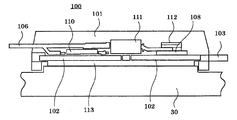
- FIGS. 4 and 5 are views showing a detailed structure of a power module 100 in which the power circuit component is integrally formed with a conductive resin together with a mold resin.
- power circuit components that is, FETs including power switching elements 107 and 108 and a motor relay switching element 109, a shunt resistor 110, and a snubber capacitor 111 are soldered on a base electrode 102 (102a to 102e) that is a conductive member.
- the upper electrode (not shown) of the FET is joined to another FET or the base electrode 102 by a jumper electrode 112 with solder (not shown).
- the control terminal 106 is similarly joined by solder (not shown) for extracting a signal from the gate electrode of the FET or the shunt resistor 110.
- the power circuit section including the upper and lower arm FETs 108 and 107, the motor relay FET 109, the shunt resistor 110, and the snubber capacitor 111 shown in FIG. 1 is configured as a power module together with the base electrode 102 that is a conductive member. Note that the snubber capacitor 111 may be omitted depending on use conditions.
- one side of the base electrode 102 is exposed on the bottom surface of the power module 100 and is thermally coupled to the heat sink 30 via a high thermal conductive material 113 made of silicone resin.
- a protrusion is provided on a part of the resin on the bottom side of the power module 100, and a uniform gap is formed between the heat sink 30 and the exposed base electrode 102.
- This uniform gap is filled with silicone resin.
- this silicone resin also makes the temperature distribution in the planar direction more uniform.
- the high thermal conductive material is not limited to silicone resin.
- the structure integrally molded with the mold resin and the structure in which the silicone resin is interposed between the conductive member exposed on one side and the heat sink allow the heat of each electronic component that is a heating element and the conductive member to be molded resin and silicone. It is made uniform in the mold module 100 through the resin, and can be radiated to the outside uniformly from the bottom surface.
- the use efficiency can be improved (performance improvement), and as a result, necessary and sufficient parts can be selected, and miniaturization and cost reduction can be achieved. Can do.
- control device 20 is arranged in front of the transmission motor shaft 2, and the power module 100 and the relay module 24 for three phases are arranged evenly on the heat sink 30,
- the entire electric power steering drive control device can be dissipated very efficiently.
- the conductive member is exposed on one side. However, if there is a margin in temperature, the entire power module may be covered with a mold resin.
- Embodiment 2 FIG. The second embodiment is intended to further improve the heat dissipation efficiency of the first embodiment, and will be described in detail using the circuit of FIG. In FIG. 1, first, the PWM drive operation of the electric motor 1 by the control device 20 will be described.
- the on-resistance of the relay FET 109 is set to be smaller than that of the arm FETs 107 and 108 and to reduce it to about 1 ⁇ 2 in consideration of the heat balance. Further, in order to reduce the temperature rise of the motor relay FET 109 having a large heat generation amount, the chip size of the motor relay FET 109 is set larger than that of the upper and lower arms 107 and 108, and approximately doubled in consideration of the heat radiation efficiency. Is desirable.
- the area of the base electrode 102c positioned below the motor relay FET 109 is set larger than the base electrodes 102b and 102d of the upper and lower arms to improve the heat radiation efficiency. I am trying.
- the base electrode is also a heating element, but also serves as a part of the heat sink. By increasing the area, the heat dissipation to the heat sink can be improved, the heat capacity near the FET can be increased, and a transient temperature rise can also be suppressed.
- there are methods for increasing the heat capacity such as increasing the thickness or soldering a copper plate or the like as a separate member on the base electrode near the FET.
- the shunt resistor 110 is inserted into the upper and lower arms or the motor line in order to detect the motor current.
- the shunt resistor 110 is inserted into the lower arm.
- the shunt resistor has a resistance value of about 1 m ⁇ .
- the shunt resistor 110 is also built in the power module 100 and integrated with the resin 101. Similar to the above-described FET, the temperature distribution can be made uniform and heat can be efficiently radiated.
- the inverter circuit normally drives the motor by the PWM method, but is required to be switched as fast as possible in order to reduce the switching loss of the FET.
- a high-frequency current flows between the upper and lower arms 108 and 107 and the power source, causing EMI such as radio noise.
- a snubber capacitor 111 (for example, a ceramic capacitor) with good high frequency characteristics is inserted in parallel with the upper and lower arms 108 and 107, and high frequency current is circulated between the upper and lower arms 108 and 107 and the snubber capacitor 111 to reduce the influence on the outside. Measures are taken. In this case, it is desirable that the physical distance between the upper and lower arms 108 and 107 and the snubber capacitor 111 is small.
- the snubber capacitor 111 since the snubber capacitor 111 is built in the power module 100, high-frequency current can be efficiently circulated in the module. In other words, this means that a large amount of high-frequency current flows through the snubber capacitor 111, and the snubber capacitor 111 itself generates a large amount of heat, and heat dissipation must be taken into consideration.
- the snubber capacitor 111 attached to the base electrodes 102d and 102e can achieve uniform temperature distribution and efficiently dissipate heat for the same reason as the shunt resistor 110. It has two advantages of improvement and heat dissipation performance.
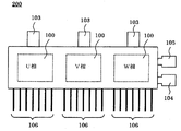
- Embodiment 3 In the first embodiment, an example in which one phase of the bridge arm is used as one power module is shown. However, the three phases may be collectively sealed in the same package.
- FIG. 6 shows the power module in this case.
- the same reference numerals as those in FIG. 4 denote the same or corresponding parts.
- a three-phase brushless motor is often used, and if the arm three-phase portion is sealed as one power module 200, the internal temperature distribution can be made uniform as in the first and second embodiments. As a result, the heat radiation efficiency is expected to improve as a whole for the three-phase arm.
- further miniaturization of the control device 20 can be achieved by sealing the arm three-phase portion as one power module.
- FIG. 7 shows an example in which the control device 20 is arranged behind the electric motor 1 in the same direction as the motor shaft 2.
- the electric motor 1 as a heating element and the heat sink 30 of the control device 20 are fixed by screws (not shown), and the entire circumference is thermally coupled.
- the control device 20 is arranged behind the electric motor 1 (opposite output side).
- the power module 100 and the relay module 24 are evenly arranged with respect to the heat sink 30, and the temperature distribution due to heat generation is made uniform.
- the heat sink 30 of the control device 20 is thermally coupled to the motor housing 49 of the electric motor 1.
- the motor housing 49 of the electric motor 1 is screwed to the gear case 13 and is thermally coupled to the entire circumference. Since the heat generated from the electric motor 1 and the control device 20 is efficiently radiated to the gear case 13, the temperature including the gear case 13 can be made uniform. Further, the motor housing 49 is exposed to the entire circumference of the motor, and high heat transfer characteristics with the air can be expected. In addition to the heat generation of the motor, the heat generation of the control device 20 is transmitted from the motor housing 49 via the heat sink 30. Heat is dissipated.
- the temperature distribution of the electric motor 1 and the control device 20 can be made uniform, and the entire temperature distribution can be made uniform as an electric power steering drive device. Can be planned.
- the power module 100 has been mainly described.
- the relay module 24 can have the same thermal design and configuration.
Abstract
Description
また、特許文献2のものは、制御装置をモータの背面に積層してその放熱性を改善しているが、積層構造のため大型化、高コスト化せざるを得ず、また熱的効率を改善するためのパワー素子の配置構成については何等言及されていない。
また、発熱体であるシャント抵抗やスナバコンデンサを内蔵することによりシャント抵抗やスナバコンデンサの発熱、放熱が前記半導体スイッチング素子と同様に効率良くかつバランスよく行われる。
以下、この発明の実施の形態を図に基づいて説明する。各図において、同一、または相当部材、部位については同一符号を付して説明する。
図1は、本発明の実施の形態1における電動式パワーステアリング駆動制御装置の全体構成を示すブロック回路図である。
また、上記モータリレー用スイッチング素子109は、正常動作時はFETをONして電動モータ1に適正な制御電流を流し、異常時はFETをOFFして電動モータ1への通電を阻止し、危険な電流が電動モータ1に流れないようにするフェールセーフ用のFETであり、異常かどうかの判定はマイクロコンピュータ26で行われる。
図2は電動式パワーステアリング駆動制御装置の断面図であり、電動モータ1と制御装置20と減速装置12とをモータ軸と同軸方向に配置し、電動モータ1と減速装置12との間、すなわちモータ軸前方に制御装置20を配置した例を示している。
図において符号150は電動式パワーステアリング駆動制御装置を示し、駆動モータ1は軸受3a、3bにより回転可能に支承された回転子軸2とこの回転子軸2の周りに装着された永久磁石6とからなる回転子4と、この回転子4の周囲に設けられた固定子5と、この固定子5を固定する鉄製のヨーク7とから構成されている。
更に、ギアケース13への放熱効果次第でヒートシンク30の厚さを薄くしたり、質量を小さくすることができる。制御装置20を電動モータ軸2の前方に配置することにより、発熱体である電動モータ1と制御装置20の温度分布が軸方向にも均一化が図れ、電動パワーステアリング駆動装置として全体の温度分布の均一化が図れる。
このように配置することにより、制御装置20における主たる発熱体である3相分のパワーモジュール100とリレーモジュール24の発熱が、ヒートシンク30へ均等に放熱され、パワーモジュール100、リレーモジュール24および制御装置20の温度分布の均一化が図れる。
先ず、導電部材であるベース電極102(102a~102e)の上に、パワー回路部品、すなわち、パワースイッチング素子107、108およびモータリレー用スイッチング素子109からなるFET、シャント抵抗110、スナバコンデンサ111が半田等で接合・配置されており、上記FETの上面電極(図示せず)はジャンパ電極112によって他のFETまたはベース電極102と図示しない半田で接合されている。一方制御用端子106はFETのゲート電極やシャント抵抗110の信号取り出し用として、同様に図示しない半田で接合されている。
ここでは、図示してはいないが、パワーモジュール100の底面側の樹脂の一部には突起が設けられており、ヒートシンク30と露出したベース電極102は均一の隙間が形成される構成となっており、この均一の隙間にシリコーン樹脂は充填される。
これにより電子部品から発生する熱を効率的に外部へ放熱できるようになっている。無論、このシリコーン樹脂によって平面方向の温度分布もより均一化されることは言うまでもない。なお、高熱伝導材はシリコーン樹脂製に限定されるものではないことはもちろんである。
なお、本実施の形態では、導電部材を片面露出させたが、温度的に余裕がある場合は、パワーモジュールをモールド樹脂にて全体を覆っても良い。
実施の形態2は実施の形態1の放熱効率の更なる改善を図ったものであり、図1の回路を利用して詳しく説明する。
図1において、先ず、制御装置20による電動モータ1のPWM駆動の動作を説明する。今、三相ブリッジ回路の上側アームFET108がオンの場合は、バッテリ60の電源端子→上側アームFET108→モータリレー用FET109→電動モータ1→他相アームへ、
また、下側アームFET107がオンの場合は、GND電極→シャント抵抗110→下側FET107→モータリレーFET109→電動モータ1→他相アームへ、
のルートでモータ電流が流れ、1周期あたりに各FETに流れる時間は、リレーFET109は上下側アームFET108、107の2倍である(リレーFET109に対して上下側アーム108、107は1/2の時間)。各FETのオン抵抗が同じ場合、電力損失比は、
アームFET107、108:リレーFET109=1:2
となる。従って各FETの放熱効率が同じ場合、温度上昇はリレーFET109がアームの2倍となる。
また、発熱量の大きいモータリレー用FET109の温度上昇を低減するため、モータリレー用FET109のチップサイズを上下側アーム107、108のそれより大きく設定し、放熱効率を考慮して略2倍にするのが望ましい。
ス電極102b、102dより大きく設定し放熱効率向上を図っている。なお、ベース電極は発熱体でもあるが、ヒートシンクの役割を一部兼ねていることは言うまでもない。面積を大きくすることで、ヒートシンクへの放熱性を高めると共に、当該FET近辺の熱容量を大きくでき、過渡的な温度上昇も抑制することができる。
なお、熱容量を大きくする手段として、ベース電極の面積以外にも、厚みを厚くしたり、FET近傍のベース電極上に別部材の銅板等を半田付けする等の手法がある。
上記実施の形態1では、ブリッジアームの一相分を1個のパワーモジュールとした例を示したが、三相分を纏めて同一パッケージに樹脂封止してもよい。図6はこの場合のパワーモジュールを示している。図中、図4と同一符号は同一又は相当部分を表している。
電動パワーステアリング装置では、三相ブラシレスモータを使う場合が多く、アーム三相分を1個のパワーモジュール200として封止すれば、実施の形態1、2と同様に、内部温度分布の均一化が図れ、アーム三相分全体として、より放熱効率の改善が期待される。また、アーム三相分を1個のパワーモジュールとして封止すれば、制御装置20の更なる小型化が図れることは言うまでもない。
図7は制御装置20をモータ軸2と同軸方向で電動モータ1の後方に配置した例を示す。
発熱体である電動モータ1と制御装置20のヒートシンク30はネジ(図示せず)で固定されており、全周が熱的に結合されている。ここで制御装置20は電動モータ1の後方(反出力側)に配置されている。制御装置20は実施の形態1~3で示したように、パワーモジュール100とリレーモジュール24がヒートシンク30に対して均等配置されており、発熱による温度分布は均一化が図られている。
また、制御装置20のヒートシンク30は電動モータ1のモータハウジング49に熱的に結合されている。
また、モータハウジング49はモータ全周が空気に晒されており、空気との高い熱伝達特性が期待でき、モータの発熱だけでなく、制御装置20の発熱はヒートシンク30を介してモータハウジング49から放熱される。
なお、上記の実施の形態は、主にパワーモジュール100について述べてきたが、リレーモジュール24についても同様の熱的設計、構成とすることができる。
24 リレーモジュール、 30 ヒートシンク、
100 パワーモジュール、 101 モールド樹脂、
107、108 パワースイッチング素子、
109 モータリレー用スイッチング素子、
110 シャント抵抗、 111 スナバコンデンサ、
113 高熱伝導材。
Claims (12)
- ブリッジ回路を構成する複数個のパワースイッチング素子と、上記パワースイッチング素子のそれぞれからモータに供給されるモータ電流をオン・オフ制御するモータリレー用スイッチング素子と、からなるパワー回路部品を導電部材上に実装し、前記パワー回路部品と前記導電部材とをモールド樹脂にて一体成形し、ヒートシンク上に当接配置したことを特徴とする電動式パワーステアリング用パワーモジュール。
- 前記モータリレー用スイッチング素子のオン抵抗は、前記ブリッジ回路を構成するパワースイッチング素子のオン抵抗より小さいことを特徴とする請求項1に記載の電動式パワーステアリング用パワーモジュール。
- 前記モータリレー用スイッチング素子のチップサイズは、前記ブリッジ回路を構成するパワースイッチング素子のチップサイズより大きいことを特徴とする請求項1に記載の電動式パワーステアリング用パワーモジュール。
- 前記モータリレー用スイッチング素子が実装された導電部材の熱容量は、前記ブリッジ回路を構成するパワースイッチング素子が実装された導電部材の熱容量より大きいことを特徴とする請求項1に記載の電動式パワーステアリング用パワーモジュール。
- 前記パワーモジュールに少なくとも1個の電流検出用シャント抵抗を実装したことを特徴とする請求項1に記載の電動式パワーステアリング用パワーモジュール。
- 前記パワーモジュールに少なくとも1個のノイズ除去用スナバコンデンサを実装したことを特徴とする請求項1に記載の電動式パワーステアリング用パワーモジュール。
- 前記パワーモジュールとヒートシンクの間に高熱伝導材を介してヒートシンク上に当接配置したことを特徴とする請求項1に記載の電動式パワーステアリング用パワーモジュール。
- 前記パワーモジュールの導電部材102の片面側は露出しており、当該露出面と前記ヒートシンクとの間に高熱伝導材を介してヒートシンク上に当接配置したことを特徴とする請求項7に記載の電動式パワーステアリング用パワーモジュール。
- 多相分を纏めて同一パッケージに樹脂封止したことを特徴とする請求項1に記載の電動式パワーステアリング用パワーモジュール。
- 電動モータとこの電動モータの駆動を制御する制御装置とを備え、請求項1~9のいずれかに記載のパワーモジュールを構成するパワー回路部品をヒートシンク上に放熱効率が均等になるように配置したことを特徴とする電動式パワーステアリング駆動制御装置。
- 電動モータと制御装置はモータ軸と同軸上に配置され、前記制御装置はモータ軸前方に配置したことを特徴とする請求項10に記載の電動式パワーステアリング駆動制御装置。
- 電動モータと制御装置はモータ軸と同軸上に配置され、前記制御装置はモータ軸後方に配置したことを特徴とする請求項10に記載の電動式パワーステアリング駆動制御装置。
Priority Applications (4)
| Application Number | Priority Date | Filing Date | Title |
|---|---|---|---|
| JP2012541762A JP5970668B2 (ja) | 2010-11-02 | 2011-04-25 | 電動式パワーステアリング用パワーモジュールおよびこれを用いた電動式パワーステアリング駆動制御装置 |
| US13/817,236 US9888613B2 (en) | 2010-11-02 | 2011-04-25 | Power module for electric power steering and electric power steering drive control apparatus using the same |
| EP11837776.1A EP2637285B1 (en) | 2010-11-02 | 2011-04-25 | Electric power steering power module and electric power steering drive control device employing same |
| CN2011800520458A CN103210571A (zh) | 2010-11-02 | 2011-04-25 | 电动式动力转向用电源模块及使用其的电动式动力转向驱动控制装置 |
Applications Claiming Priority (2)
| Application Number | Priority Date | Filing Date | Title |
|---|---|---|---|
| JP2010-246306 | 2010-11-02 | ||
| JP2010246306 | 2010-11-02 |
Publications (1)
| Publication Number | Publication Date |
|---|---|
| WO2012060123A1 true WO2012060123A1 (ja) | 2012-05-10 |
Family
ID=46024247
Family Applications (1)
| Application Number | Title | Priority Date | Filing Date |
|---|---|---|---|
| PCT/JP2011/060056 WO2012060123A1 (ja) | 2010-11-02 | 2011-04-25 | 電動式パワーステアリング用パワーモジュールおよびこれを用いた電動式パワーステアリング駆動制御装置 |
Country Status (5)
| Country | Link |
|---|---|
| US (1) | US9888613B2 (ja) |
| EP (1) | EP2637285B1 (ja) |
| JP (2) | JP5970668B2 (ja) |
| CN (2) | CN103210571A (ja) |
| WO (1) | WO2012060123A1 (ja) |
Cited By (13)
| Publication number | Priority date | Publication date | Assignee | Title |
|---|---|---|---|---|
| WO2013140906A1 (ja) * | 2012-03-22 | 2013-09-26 | 日立オートモティブシステムズ株式会社 | 電力変換装置、電動パワーステアリングシステム、電気自動車、電子制御スロットル、電動ブレーキ |
| JP2014057494A (ja) * | 2012-09-14 | 2014-03-27 | Denso Corp | 車両用回転電機 |
| JP2015039295A (ja) * | 2010-11-02 | 2015-02-26 | 三菱電機株式会社 | 電動式パワーステアリング用パワーモジュールおよびこれを用いた電動式パワーステアリング駆動制御装置 |
| WO2016104088A1 (ja) * | 2014-12-24 | 2016-06-30 | 日本精工株式会社 | パワー半導体モジュール及びこれを用いた電動パワーステアリング装置 |
| WO2016147345A1 (ja) * | 2015-03-18 | 2016-09-22 | 株式会社テーケィアール | 電源モジュールおよびそれを用いたエアコンディショナ室外機 |
| JP2016213917A (ja) * | 2015-04-30 | 2016-12-15 | 株式会社ジェイテクト | 半導体モジュール |
| WO2017022094A1 (ja) * | 2015-08-05 | 2017-02-09 | 三菱電機株式会社 | インバータ一体型モータ |
| US9800563B2 (en) | 2011-11-03 | 2017-10-24 | Huawei Technologies Co., Ltd. | Method and device for processing data security channel |
| JP2018129883A (ja) * | 2017-02-06 | 2018-08-16 | 株式会社デンソー | 半導体装置 |
| WO2019038849A1 (ja) * | 2017-08-23 | 2019-02-28 | 三菱電機株式会社 | 電動駆動装置 |
| JP2019088162A (ja) * | 2017-11-09 | 2019-06-06 | 株式会社ジェイテクト | モータ装置 |
| JP2020156175A (ja) * | 2019-03-19 | 2020-09-24 | 富士電機株式会社 | 電力変換装置 |
| US20200395867A1 (en) * | 2018-02-20 | 2020-12-17 | Mitsubishi Electric Corporation | Power semiconductor module and power conversion apparatus including the same |
Families Citing this family (19)
| Publication number | Priority date | Publication date | Assignee | Title |
|---|---|---|---|---|
| JP4911271B1 (ja) * | 2010-12-24 | 2012-04-04 | トヨタ自動車株式会社 | トルク検出装置 |
| US20130062137A1 (en) * | 2011-09-14 | 2013-03-14 | Hitachi Automotive Systems, Ltd. | Electric Power Steering System |
| DE102013008193A1 (de) * | 2013-05-14 | 2014-11-20 | Audi Ag | Vorrichtung und elektrische Baugruppe zum Wandeln einer Gleichspannung in eine Wechselspannung |
| DE102014205957A1 (de) * | 2014-03-31 | 2015-10-01 | Lemförder Electronic GmbH | Treiberbaugruppe |
| DE102014205956A1 (de) * | 2014-03-31 | 2015-10-15 | Lemförder Electronic GmbH | Treiberbaugruppe |
| EP3142144A4 (en) * | 2014-05-09 | 2018-03-21 | Mitsubishi Electric Corporation | Semiconductor module |
| JP6157752B2 (ja) * | 2014-09-09 | 2017-07-05 | 三菱電機株式会社 | 多相交流モータ駆動用インバータ装置 |
| JP6366809B2 (ja) * | 2015-02-18 | 2018-08-01 | 三菱電機株式会社 | 一体型電動パワーステアリング装置 |
| US10720873B2 (en) * | 2015-02-23 | 2020-07-21 | Mitsubishi Electric Corporation | Electric drive device and control method for same |
| US9768607B2 (en) * | 2015-05-11 | 2017-09-19 | Infineon Technologies Ag | System and method for a multi-phase snubber circuit |
| US10314169B2 (en) | 2015-08-21 | 2019-06-04 | Renesas Electronics Corporation | Electronic device |
| FR3049315B1 (fr) * | 2016-03-23 | 2018-04-13 | Valeo Systemes De Controle Moteur | Compresseur de suralimentation electrique comprenant un dispositif de connexion electrique |
| JP6673246B2 (ja) * | 2017-02-06 | 2020-03-25 | 株式会社デンソー | 半導体装置 |
| US10903619B2 (en) * | 2017-05-17 | 2021-01-26 | Mitsubishi Electric Corporation | Semiconductor package |
| JP6723201B2 (ja) | 2017-07-13 | 2020-07-15 | 日立オートモティブシステムズ株式会社 | 電動駆動装置及び電動パワーステアリング装置 |
| US11374469B2 (en) | 2018-01-23 | 2022-06-28 | MAGicALL, Inc. | Electric machine with integrated controller |
| FR3083191B1 (fr) * | 2018-06-29 | 2020-06-19 | Valeo Systemes D'essuyage | Moto-reducteur, systeme d'essuyage et procede de commande associes |
| JP7183591B2 (ja) | 2018-07-02 | 2022-12-06 | 富士電機株式会社 | 半導体装置 |
| JP6968967B1 (ja) * | 2020-10-30 | 2021-11-24 | 日立Astemo株式会社 | パワー半導体装置、電力変換装置、および電動システム |
Citations (5)
| Publication number | Priority date | Publication date | Assignee | Title |
|---|---|---|---|---|
| JP2002345211A (ja) | 2001-05-17 | 2002-11-29 | Mitsubishi Electric Corp | 電動式パワーステアリング装置 |
| JP2004064934A (ja) | 2002-07-30 | 2004-02-26 | Honda Motor Co Ltd | モータ駆動装置 |
| JP2009027066A (ja) * | 2007-07-23 | 2009-02-05 | Meidensha Corp | モジュール構造 |
| JP2009278134A (ja) * | 2009-08-24 | 2009-11-26 | Hitachi Ltd | パワーモジュールおよびインバータ |
| WO2010007672A1 (ja) * | 2008-07-16 | 2010-01-21 | 三菱電機株式会社 | 電動パワーステアリング装置、及び制御装置一体型電動機 |
Family Cites Families (32)
| Publication number | Priority date | Publication date | Assignee | Title |
|---|---|---|---|---|
| JPH0741164Y2 (ja) | 1989-09-26 | 1995-09-20 | 関西日本電気株式会社 | 半導体装置 |
| JPH0617249U (ja) | 1992-07-29 | 1994-03-04 | サンケン電気株式会社 | 半導体装置 |
| US5491111A (en) * | 1994-10-26 | 1996-02-13 | Tai; George | Method of making a semiconductor diode |
| JPH09162194A (ja) * | 1995-12-08 | 1997-06-20 | Mitsubishi Electric Corp | ヘテロ接合バイポーラトランジスタ |
| JPH09199645A (ja) | 1996-01-17 | 1997-07-31 | Mitsubishi Electric Corp | 半導体装置および半導体モジュール |
| JP3458768B2 (ja) * | 1999-06-10 | 2003-10-20 | 株式会社デンソー | 負荷駆動装置 |
| US6215681B1 (en) * | 1999-11-09 | 2001-04-10 | Agile Systems Inc. | Bus bar heat sink |
| JP3774624B2 (ja) * | 2000-10-18 | 2006-05-17 | 三菱電機株式会社 | 電動パワーステアリング装置 |
| JP2002237644A (ja) * | 2001-02-09 | 2002-08-23 | Hitachi Cable Ltd | 光送信器 |
| TWI257181B (en) * | 2003-07-28 | 2006-06-21 | Rohm Co Ltd | Semiconductor module |
| JP2005051031A (ja) | 2003-07-28 | 2005-02-24 | Rohm Co Ltd | 半導体モジュール |
| CN100483704C (zh) * | 2003-08-14 | 2009-04-29 | 国际整流器公司 | 用于epas/ehpas应用的模块 |
| US6933593B2 (en) * | 2003-08-14 | 2005-08-23 | International Rectifier Corporation | Power module having a heat sink |
| JP3891157B2 (ja) | 2003-08-25 | 2007-03-14 | 株式会社デンソー | モータ駆動装置 |
| KR100661725B1 (ko) * | 2004-12-30 | 2006-12-26 | 엘지.필립스 엘시디 주식회사 | 박막 트랜지스터 어레이 기판 및 그 제조 방법 |
| JP5067159B2 (ja) * | 2005-07-11 | 2012-11-07 | 日本精工株式会社 | 電動パワーステアリング装置 |
| KR101039200B1 (ko) * | 2006-04-11 | 2011-06-03 | 닛본 세이고 가부시끼가이샤 | 전동파워스티어링장치 |
| JP2007295658A (ja) * | 2006-04-21 | 2007-11-08 | Nsk Ltd | モータ制御装置及びこれを用いた電動パワーステアリング制御装置 |
| JP4246212B2 (ja) * | 2006-04-21 | 2009-04-02 | 三菱電機株式会社 | 電動式パワーステアリング装置 |
| JP2009018668A (ja) | 2007-07-11 | 2009-01-29 | Jtekt Corp | 操舵制御装置 |
| JP5092654B2 (ja) * | 2007-09-28 | 2012-12-05 | 株式会社デンソー | 電力変換装置 |
| JP5169353B2 (ja) | 2008-03-18 | 2013-03-27 | 三菱電機株式会社 | パワーモジュール |
| JP4623125B2 (ja) * | 2008-04-07 | 2011-02-02 | 三菱電機株式会社 | 電動パワ−ステアリング用電動モ−タ装置および電動パワーステアリング装置 |
| US8930083B2 (en) * | 2008-08-25 | 2015-01-06 | Steering Solutions Ip Holding Corporation | Electric power steering system having fail-safe control module operation |
| JP4909961B2 (ja) | 2008-09-02 | 2012-04-04 | 日立オートモティブシステムズ株式会社 | 電動パワーステアリング用制御装置 |
| JP5171520B2 (ja) * | 2008-09-30 | 2013-03-27 | 日立オートモティブシステムズ株式会社 | 電力変換装置 |
| JP2010100217A (ja) * | 2008-10-24 | 2010-05-06 | Jtekt Corp | 電動パワーステアリング装置 |
| CN101609236A (zh) * | 2009-07-15 | 2009-12-23 | 上海广电光电子有限公司 | 薄膜晶体管阵列基板制造方法 |
| JP5242629B2 (ja) | 2010-05-10 | 2013-07-24 | 株式会社東芝 | 電力用半導体素子 |
| JP5201171B2 (ja) * | 2010-05-21 | 2013-06-05 | 株式会社デンソー | 半導体モジュール、および、それを用いた駆動装置 |
| JP5012953B2 (ja) * | 2010-05-21 | 2012-08-29 | 株式会社デンソー | 駆動装置 |
| JP5970668B2 (ja) * | 2010-11-02 | 2016-08-17 | 三菱電機株式会社 | 電動式パワーステアリング用パワーモジュールおよびこれを用いた電動式パワーステアリング駆動制御装置 |
-
2011
- 2011-04-25 JP JP2012541762A patent/JP5970668B2/ja not_active Expired - Fee Related
- 2011-04-25 EP EP11837776.1A patent/EP2637285B1/en active Active
- 2011-04-25 CN CN2011800520458A patent/CN103210571A/zh active Pending
- 2011-04-25 WO PCT/JP2011/060056 patent/WO2012060123A1/ja active Application Filing
- 2011-04-25 CN CN201811147746.XA patent/CN109194153A/zh active Pending
- 2011-04-25 US US13/817,236 patent/US9888613B2/en active Active
-
2014
- 2014-11-13 JP JP2014230427A patent/JP2015039295A/ja active Pending
Patent Citations (6)
| Publication number | Priority date | Publication date | Assignee | Title |
|---|---|---|---|---|
| JP2002345211A (ja) | 2001-05-17 | 2002-11-29 | Mitsubishi Electric Corp | 電動式パワーステアリング装置 |
| JP2004064934A (ja) | 2002-07-30 | 2004-02-26 | Honda Motor Co Ltd | モータ駆動装置 |
| JP3957177B2 (ja) | 2002-07-30 | 2007-08-15 | 本田技研工業株式会社 | モータ駆動装置 |
| JP2009027066A (ja) * | 2007-07-23 | 2009-02-05 | Meidensha Corp | モジュール構造 |
| WO2010007672A1 (ja) * | 2008-07-16 | 2010-01-21 | 三菱電機株式会社 | 電動パワーステアリング装置、及び制御装置一体型電動機 |
| JP2009278134A (ja) * | 2009-08-24 | 2009-11-26 | Hitachi Ltd | パワーモジュールおよびインバータ |
Non-Patent Citations (1)
| Title |
|---|
| See also references of EP2637285A4 |
Cited By (26)
| Publication number | Priority date | Publication date | Assignee | Title |
|---|---|---|---|---|
| JP2015039295A (ja) * | 2010-11-02 | 2015-02-26 | 三菱電機株式会社 | 電動式パワーステアリング用パワーモジュールおよびこれを用いた電動式パワーステアリング駆動制御装置 |
| US9800563B2 (en) | 2011-11-03 | 2017-10-24 | Huawei Technologies Co., Ltd. | Method and device for processing data security channel |
| JPWO2013140906A1 (ja) * | 2012-03-22 | 2015-08-03 | 日立オートモティブシステムズ株式会社 | 電力変換装置、電動パワーステアリングシステム、電気自動車、電子制御スロットル、電動ブレーキ |
| US9490732B2 (en) | 2012-03-22 | 2016-11-08 | Hitachi Automotive Systems, Ltd. | Power conversion apparatus, electronic steering system, electric vehicle, electronic control throttle and power brake |
| WO2013140906A1 (ja) * | 2012-03-22 | 2013-09-26 | 日立オートモティブシステムズ株式会社 | 電力変換装置、電動パワーステアリングシステム、電気自動車、電子制御スロットル、電動ブレーキ |
| JP2014057494A (ja) * | 2012-09-14 | 2014-03-27 | Denso Corp | 車両用回転電機 |
| WO2016104088A1 (ja) * | 2014-12-24 | 2016-06-30 | 日本精工株式会社 | パワー半導体モジュール及びこれを用いた電動パワーステアリング装置 |
| US10096572B2 (en) | 2014-12-24 | 2018-10-09 | Nsk Ltd. | Power semiconductor module and electric power steering apparatus using the same |
| JPWO2016147345A1 (ja) * | 2015-03-18 | 2018-01-18 | 株式会社テーケィアール | 電源モジュールおよびそれを用いたエアコンディショナ室外機 |
| WO2016147345A1 (ja) * | 2015-03-18 | 2016-09-22 | 株式会社テーケィアール | 電源モジュールおよびそれを用いたエアコンディショナ室外機 |
| JP2016213917A (ja) * | 2015-04-30 | 2016-12-15 | 株式会社ジェイテクト | 半導体モジュール |
| US10673309B2 (en) | 2015-08-05 | 2020-06-02 | Mitsubishi Electric Corporation | Inverter-integrated motor |
| WO2017022094A1 (ja) * | 2015-08-05 | 2017-02-09 | 三菱電機株式会社 | インバータ一体型モータ |
| JPWO2017022094A1 (ja) * | 2015-08-05 | 2017-10-19 | 三菱電機株式会社 | インバータ一体型モータ |
| JP2018129883A (ja) * | 2017-02-06 | 2018-08-16 | 株式会社デンソー | 半導体装置 |
| CN111033973B (zh) * | 2017-08-23 | 2022-02-11 | 三菱电机株式会社 | 电动驱动装置 |
| JPWO2019038849A1 (ja) * | 2017-08-23 | 2019-12-26 | 三菱電機株式会社 | 電動駆動装置 |
| CN111033973A (zh) * | 2017-08-23 | 2020-04-17 | 三菱电机株式会社 | 电动驱动装置 |
| WO2019038849A1 (ja) * | 2017-08-23 | 2019-02-28 | 三菱電機株式会社 | 電動駆動装置 |
| US11670991B2 (en) | 2017-08-23 | 2023-06-06 | Mitsubishi Electric Corporation | Electric driving apparatus |
| JP2019088162A (ja) * | 2017-11-09 | 2019-06-06 | 株式会社ジェイテクト | モータ装置 |
| JP7222175B2 (ja) | 2017-11-09 | 2023-02-15 | 株式会社ジェイテクト | モータ装置 |
| US20200395867A1 (en) * | 2018-02-20 | 2020-12-17 | Mitsubishi Electric Corporation | Power semiconductor module and power conversion apparatus including the same |
| US11711025B2 (en) * | 2018-02-20 | 2023-07-25 | Mitsubishi Electric Corporation | Power semiconductor module and power conversion apparatus including the same |
| JP2020156175A (ja) * | 2019-03-19 | 2020-09-24 | 富士電機株式会社 | 電力変換装置 |
| JP7310188B2 (ja) | 2019-03-19 | 2023-07-19 | 富士電機株式会社 | 電力変換装置 |
Also Published As
| Publication number | Publication date |
|---|---|
| US20130141871A1 (en) | 2013-06-06 |
| US9888613B2 (en) | 2018-02-06 |
| CN109194153A (zh) | 2019-01-11 |
| EP2637285A1 (en) | 2013-09-11 |
| JP2015039295A (ja) | 2015-02-26 |
| EP2637285A4 (en) | 2018-03-28 |
| JPWO2012060123A1 (ja) | 2014-05-12 |
| EP2637285B1 (en) | 2020-04-01 |
| JP5970668B2 (ja) | 2016-08-17 |
| CN103210571A (zh) | 2013-07-17 |
Similar Documents
| Publication | Publication Date | Title |
|---|---|---|
| JP5970668B2 (ja) | 電動式パワーステアリング用パワーモジュールおよびこれを用いた電動式パワーステアリング駆動制御装置 | |
| JP5039171B2 (ja) | 電動式駆動装置およびその電動式駆動装置を搭載した電動式パワーステアリング装置 | |
| JP5496357B2 (ja) | 電動パワーステアリング用モータ駆動制御装置 | |
| KR101204624B1 (ko) | 제어 장치 일체형 전동 파워 스티어링 장치용 모터 및 전동 파워 스티어링 장치 | |
| JP6582568B2 (ja) | 駆動装置、および、これを用いた電動パワーステアリング装置 | |
| KR101260577B1 (ko) | 전동 파워 스티어링 장치, 및 제어 장치 일체형 전동기 | |
| JP6026048B1 (ja) | 電動パワーステアリング用モータ駆動制御装置 | |
| JP6179476B2 (ja) | 駆動装置、および、これを用いた電動パワーステアリング装置 | |
| JP5946962B2 (ja) | 電力変換装置 | |
| US9123693B2 (en) | Mold module utilized as power unit of electric power steering apparatus and electric power steering apparatus | |
| JP6444495B2 (ja) | 電動パワーステアリング駆動装置 | |
| WO2016132474A1 (ja) | 一体型電動パワーステアリング装置 | |
| JP5619279B2 (ja) | 電動パワーステアリング装置 | |
| JP5752276B2 (ja) | 駆動装置一体型回転電機 | |
| JP2016034205A (ja) | 駆動装置、および、これを用いた電動パワーステアリング装置 | |
| JP2012248737A (ja) | 半導体装置、および、それを用いた駆動装置 | |
| JP2016062953A (ja) | 電子制御ユニット及びこれを用いた回転電機 | |
| JP4981939B2 (ja) | 電動式駆動装置および電動式パワーステアリング装置 | |
| JP6870711B2 (ja) | 駆動装置、および、これを用いた電動パワーステアリング装置 | |
| JP6983338B2 (ja) | 電動駆動装置 | |
| JP6934985B1 (ja) | 回転電機 | |
| WO2023209787A1 (ja) | 電動パワーステアリング装置 |
Legal Events
| Date | Code | Title | Description |
|---|---|---|---|
| 121 | Ep: the epo has been informed by wipo that ep was designated in this application |
Ref document number: 11837776 Country of ref document: EP Kind code of ref document: A1 |
|
| ENP | Entry into the national phase |
Ref document number: 2012541762 Country of ref document: JP Kind code of ref document: A |
|
| WWE | Wipo information: entry into national phase |
Ref document number: 13817236 Country of ref document: US |
|
| WWE | Wipo information: entry into national phase |
Ref document number: 2011837776 Country of ref document: EP |
|
| NENP | Non-entry into the national phase |
Ref country code: DE |